

Page 1
EDK94AZHX
.M^d
L−force Drives
Montageanleitung
Mounting Instructions
Instructions de montage
Instrucciones para el montaje
Istruzioni per il montaggio
9400
Ä.M^dä
E94AZHX0051
Motorbremsen−Ansteuerung
Motor Brake Control
Module de pilotage du frein de parking
Control de freno de motor
Modulo di comando freno motore
Page 2

Lesen Sie zuerst diese Anleitung und die Dokumentation zum Grundgerät,
bevor Sie mit den Arbeiten beginnen!
Beachten Sie die enthaltenen Sicherheitshinweise.
Please read these instructions and the documentation of the standard
device before you start working!
Observe the safety instructions given therein!
Lire le présent fascicule et la documentation relative à l’appareil de base
avant toute manipulation de l’équipement !
Respecter les consignes de sécurité fournies.
Lea estas instrucciones y la documentación del equipo básico antes de
empezar a trabajar.
Observe las instrucciones de seguridad indicadas.
Prima di iniziare qualsiasi intervento, leggere le presenti istruzioni e la
documentazione relativa al dispositivo di base.
Osservare le note di sicurezza.
Page 3

Inhalt i
1 Über diese Dokumentation 4. . . . . . . . . . . . . . . . . . . . . . . . . . . . . . . . . . . . . . . . . .
Informationen zur Gültigkeit 4. . . . . . . . . . . . . . . . . . . . . . . . . . . . . . . . . . . . . . . . .
Zielgruppe 4. . . . . . . . . . . . . . . . . . . . . . . . . . . . . . . . . . . . . . . . . . . . . . . . . . . . . . . .
Verwendete Konventionen 4. . . . . . . . . . . . . . . . . . . . . . . . . . . . . . . . . . . . . . . . . .
Verwendete Hinweise 5. . . . . . . . . . . . . . . . . . . . . . . . . . . . . . . . . . . . . . . . . . . . . . .
2 Sicherheitshinweise 7. . . . . . . . . . . . . . . . . . . . . . . . . . . . . . . . . . . . . . . . . . . . . . . .
Allgemeine Sicherheits− und Anwendungshinweise 7. . . . . . . . . . . . . . . . . . . . . .
Sicherheitshinweise für die Installation nach UL oder UR 8. . . . . . . . . . . . . . . . . .
3 Produktbeschreibung 9. . . . . . . . . . . . . . . . . . . . . . . . . . . . . . . . . . . . . . . . . . . . . . .
Lieferumfang 9. . . . . . . . . . . . . . . . . . . . . . . . . . . . . . . . . . . . . . . . . . . . . . . . . . . . . .
Übersicht 9. . . . . . . . . . . . . . . . . . . . . . . . . . . . . . . . . . . . . . . . . . . . . . . . . . . . . . . . .
Identifikation 10. . . . . . . . . . . . . . . . . . . . . . . . . . . . . . . . . . . . . . . . . . . . . . . . . . . . . .
4 Technische Daten 11. . . . . . . . . . . . . . . . . . . . . . . . . . . . . . . . . . . . . . . . . . . . . . . . . .
Allgemeine Daten und Einsatzbedingungen 11. . . . . . . . . . . . . . . . . . . . . . . . . . .
5 Mechanische Installation 12. . . . . . . . . . . . . . . . . . . . . . . . . . . . . . . . . . . . . . . . . . . .
Montageschritte 12. . . . . . . . . . . . . . . . . . . . . . . . . . . . . . . . . . . . . . . . . . . . . . . . . . .
6 Elektrische Installation 13. . . . . . . . . . . . . . . . . . . . . . . . . . . . . . . . . . . . . . . . . . . . . .
Wichtige Hinweise 13. . . . . . . . . . . . . . . . . . . . . . . . . . . . . . . . . . . . . . . . . . . . . . . . .
Zulässige Bremsenleitungslänge 14. . . . . . . . . . . . . . . . . . . . . . . . . . . . . . . . . . . . .
Potenzialtrennung 15. . . . . . . . . . . . . . . . . . . . . . . . . . . . . . . . . . . . . . . . . . . . . . . . .
Anschlussdaten 16. . . . . . . . . . . . . . . . . . . . . . . . . . . . . . . . . . . . . . . . . . . . . . . . . . . .
Verdrahtungsbeispiele 17. . . . . . . . . . . . . . . . . . . . . . . . . . . . . . . . . . . . . . . . . . . . . .
EDK94AZHX DE/EN/FR/ES/IT 3.0
3
Page 4

1 Über diese Dokumentation
Informationen zur Gültigkeit
0Abb. 0Tab. 0
1 Über diese Dokumentation
Informationen zur Gültigkeit
Diese Anleitung ist gültig für
ƒ Motorbremsen−Ansteuerung E94AZHX0051
Zielgruppe
Diese Dokumentation richtet sich an qualifiziertes Fachpersonal nach IEC 60364.
Qualifiziertes Fachpersonal sind Personen, die für die auszuführenden Tätigkeiten bei der
Aufstellung, Montage, Inbetriebsetzung und dem Betrieb des Produkts über entsprechende
Qualifikationen verfügen.
Tipp!
Informationen und Hilfsmittel rund um die Lenze−Produkte finden Sie im
Download−Bereich unter
http://www.Lenze.com
Verwendete Konventionen
Informationsart Auszeichnung Beispiele/Hinweise
Zahlenschreibweise
Dezimaltrennzeichen
Textauszeichnung
Programmname » « PC−Software
Symbole
Seitenverweis
Dokumentationsverweis
Punkt Es wird generell der Dezimalpunkt
verwendet.
Zum Beispiel: 1234.56
Zum Beispiel: »Engineer«, »Global
Drive Control« (GDC)
Verweis auf eine andere Seite mit zusätzlichen Informationen
Zum Beispiel: 16 = siehe Seite 16
Verweis auf eine andere Dokumentation mit zusätzlichen Informationen
Zum Beispiel: EDKxxx = siehe
Dokumentation EDKxxx
4
EDK94AZHX DE/EN/FR/ES/IT 3.0
Page 5
Über diese Dokumentation
Verwendete Hinweise
Verwendete Hinweise
Um auf Gefahren und wichtige Informationen hinzuweisen, werden in dieser Dokumentation folgende Piktogramme und Signalwörter verwendet:
Sicherheitshinweise
Aufbau der Sicherheitshinweise:
Gefahr!
(kennzeichnet die Art und die Schwere der Gefahr)
Hinweistext
(beschreibt die Gefahr und gibt Hinweise, wie sie vermieden werden kann)
Piktogramm und Signalwort Bedeutung
Gefahr von Personenschäden durch gefährliche elektrische Spannung
Gefahr!
Gefahr!
Stop!
Hinweis auf eine unmittelbar drohende Gefahr, die den
Tod oder schwere Verletzungen zur Folge haben kann,
wenn nicht die entsprechenden Maßnahmen getroffen
werden.
Gefahr von Personenschäden durch eine allgemeine Gefahrenquelle
Hinweis auf eine unmittelbar drohende Gefahr, die den
Tod oder schwere Verletzungen zur Folge haben kann,
wenn nicht die entsprechenden Maßnahmen getroffen
werden.
Gefahr von Sachschäden
Hinweis auf eine mögliche Gefahr, die Sachschäden zur
Folge haben kann, wenn nicht die entsprechenden Maßnahmen getroffen werden.
1
EDK94AZHX DE/EN/FR/ES/IT 3.0
5
Page 6

1 Über diese Dokumentation
Verwendete Hinweise
Anwendungshinweise
Piktogramm und Signalwort Bedeutung
Hinweis!
Tipp!
Spezielle Sicherheitshinweise und Anwendungshinweise
Piktogramm und Signalwort Bedeutung
Warnings!
Warnings!
Wichtiger Hinweis für die störungsfreie Funktion
Nützlicher Tipp für die einfache Handhabung
Verweis auf andere Dokumentation
Sicherheitshinweis oder Anwendungshinweis für den
Betrieb nach UL− oder CSA−Anforderungen.
Die Maßnahmen sind erforderlich, um die Anforderungen
nach UL oder CSA zu erfüllen.
6
EDK94AZHX DE/EN/FR/ES/IT 3.0
Page 7

Allgemeine Sicherheits− und Anwendungshinweise
2 Sicherheitshinweise
Allgemeine Sicherheits− und Anwendungshinweise
Stop!
Die Motorbremsen−Ansteuerung beinhaltet einen elektronischen Schalter, der
eine 24 V−Motorhaltebremse ansteuern kann.
An die Motorbremsen−Ansteuerung dürfen nur Motorhaltebremsen
angeschlossen werden, die den in den Technischen Daten genannten
zulässigen Daten entsprechen. (Ggf. muss die Haltebremse ohne
Motorbremsen−Ansteuerung über einen digitalen Ausgang und ein
Koppelrelais angesteuert werden.)
Werden die in den Technischen Daten genannten zulässigen Werte nicht
eingehalten:
ƒ kann die Motorbremsen−Ansteuerung zerstört werden.
ƒ ist ein sicherer Betrieb der Motorhaltebremse nicht gewährleistet.
Beachten Sie weitere Hinweise in der Dokumentation zum Grundgerät!
Sicherheitshinweise
2
EDK94AZHX DE/EN/FR/ES/IT 3.0
7
Page 8

2 Sicherheitshinweise
Sicherheitshinweise für die Installation nach UL oder UR
Sicherheitshinweise für die Installation nach UL oder U
R
Warnings!
ƒ Only for use with series E94.
ƒ The Voltage rating of the fuses must at least be suitable for the input
voltage of the device.
ƒ Use 60/75 °C copper wire only, except for control circuits.
ƒ Maximum surrounding air temperature: 55 °C.
ƒ Load at "Brake Output" is provided for "dc pilot duty".
ƒ For use in a pollution degree 2 environment.
Warnings!
ƒ Equipement destiné uniquement à être utilisé avec la série E94.
ƒ La tension des fusibles doit être adaptée à la tension d’entrée de
l’équipement (exigence minimale).
ƒ Utiliser exclusivement des conducteurs en cuivre 60/75 °C, sauf pour la
partie commande.
ƒ Température ambiante maximale : 55 °C.
ƒ Charge côté "sortie du frein" fournie pour "cycle pilote CC".
ƒ Equipement destiné à être utilisé dans un environnement caractérisé par le
degré de pollution 2.
8
EDK94AZHX DE/EN/FR/ES/IT 3.0
Page 9

3 Produktbeschreibung
Lieferumfang
Pos. Beschreibung
Motorbremsen−Ansteuerung E94AZHX0051
Montageanleitung
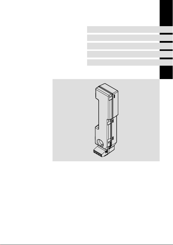
Übersicht
Produktbeschreibung
Lieferumfang
3
Pos. Beschreibung
Typenschild
Anschluss Montagesockel
X107 Anschluss Versorgung und Bremse
EDK94AZHX DE/EN/FR/ES/IT 3.0
E94AZH001
9
Page 10

3 Produktbeschreibung
Identifikation
Identifikation
E94AZH002
Typenschlüssel
Produktreihe
Gerätegeneration
Zubehör
Typ Motorbremsen−Ansteuerung
Bemessungsstrom
005 = 2,5 A
Spannungsklasse
1 = 24 V
10
E94 A Z H X 005 1
EDK94AZHX DE/EN/FR/ES/IT 3.0
Page 11
Allgemeine Daten und Einsatzbedingungen
Technische Daten
4 Technische Daten
Allgemeine Daten und Einsatzbedingungen
Normen
Konformität CE Niederspannungsrichtlinie
Approbationen UL (only for use with E94 series) UL508, Industrial Control Equipment,
Einsatzbedingungen
Die Einsatzbedingungen entsprechen denen des Grundgerätes, an das es angeschlossen
wird.
Allgemeine elektrische Daten
Schalthäufigkeit max. 6/min
Schaltzeiten Im Vergleich zur Verzögerungszeit der Bremse vernachlässigbar.
Lebensdauer > 10 Millionen Zyklen
Schutz gegen
Überlast Nein
Kurzschluss der Anschlussklemmen
Verpolung am Eingang Ja
1)
Isolation
Siehe Dokumentation zur Bremse.
Ja
Doppelte Isolierung (EN61800−5−1: V
Separation (UL: V
Bem
Bemessungsdaten
Spannung Strom Leistung Abschaltenergie
Typ UDC [V] IDC [A] PDC [W] E [Ws]
E94AZHX0051 18 ... 30 0,3 ... 2,5 max. 55 max. 5
Underwriter Laboratories (File−No.
E232497)
= 300 V AC),
= 500 V AC)
Bem
4
EDK94AZHX DE/EN/FR/ES/IT 3.0
11
Page 12

5 Mechanische Installation
Montageschritte
5 Mechanische Installation
Montageschritte
Bei der Installation die Hinweise aus der Dokumentation zum Grundgerät
beachten!
Montageschritte
1. Motorbremsen−Ansteuerung auf die Klemme des Montagesockels stecken.
2. Kontrollieren, dass beide Klammern in den Nuten der
Motorbremsen−Ansteuerung einrasten.
12
EDK94AZHX DE/EN/FR/ES/IT 3.0
E94AZH003
Page 13

Elektrische Installation
Wichtige Hinweise
6 Elektrische Installation
Wichtige Hinweise
Bei der Installation die Hinweise aus der Dokumentation zum Grundgerät
beachten!
Stop!
Anforderungen an die Bremsenleitung (Anschluss BD1/BD2):
ƒ Bremsenleitungen unbedingt geschirmt ausführen, wenn sie in der
Motorleitung mitgeführt werden.
– Der Betrieb mit ungeschirmten Bremsenleitungen kann die
Motorbremsen−Ansteuerung zerstören.
– Wir empfehlen die Verwendung von Lenze−Systemleitungen
(Motorleitung mit separat geschirmten Zusatzadern).
ƒ Achten Sie bei einer Permanentmagnet−Haltebremse auf korrekte Polung
der Bremsenleitung.
– Sind die Anschlüsse vertauscht, lüftet die Bremse nicht. Da der Motor
gegen die geschlossene Bremse läuft, kann die Bremse zerstört werden.
ƒ Schirm beidseitig auf PE legen.
Anforderung an die Versorgungsspannung U
ƒ Die Motorbremsen−Ansteuerung immer mit einer separaten
24 V−Versorgung versorgen.
– Eine gemeinsame Versorgung der Motorbremsen−Ansteuerung und der
Antriebsregler−Steuerkarte ist nicht zulässig, da andernfalls die doppelte
Isolierung zwischen beiden Komponenten reduziert wird.
ƒ U
so einstellen, dass die Betriebsspannung der Bremse im zulässigen
DC
Bereich liegt und dass die maximale Versorgungsspannung der
Motorbremsen−Ansteuerung nicht überschritten wird.
(Anschluss +/−):
DC
6
EDK94AZHX DE/EN/FR/ES/IT 3.0
13
Page 14

6 Elektrische Installation
Zulässige Bremsenleitungslänge
Zulässige Bremsenleitungslänge
200
180
160
140
120
100
[m]
max
80
L
60
40
20
0
0 0.25 0.5 0.75 1 1.25 1.5 1.75 2 2.25 2.5
IBr [A]
L
Maximale Bremsenleitungslänge in [m]
max
I
Bremsenstrom in [A]
BR
Versorgungsspannung der Motorbremsen−Ansteuerung
U
DC
14
UDC = 28 V DC
UDC = 24 V DC
1 mm2 (AWG 16)
0.75 mm2 (AWG 18)
0.5 mm2 (AWG 20)
1 mm2 (AWG 16)
0.75 mm2 (AWG 18)
0.5 mm2 (AWG 20)
E94AZH004
EDK94AZHX DE/EN/FR/ES/IT 3.0
Page 15

Potenzialtrennung
24 V
Elektrische Installation
Potenzialtrennung
Antriebsregler 9400
Steuerkarte
Motorbremsen−Ansteuerung
U V W BD1 BD2 + −
3~ Motor Bremse 24 V
Basisisolierung in der
Lenze−Systemleitung
6
doppelte
Isolierung
EDK94AZHX DE/EN/FR/ES/IT 3.0
15
Page 16
6 Elektrische Installation
Anschlussdaten
Anschlussdaten
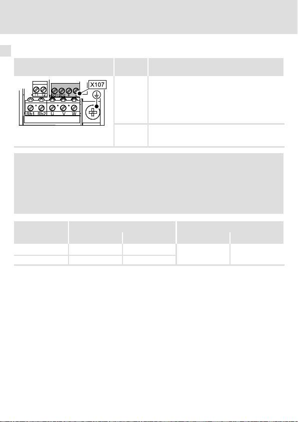
Klemme X107 Beschrif-
SSP940X107
tung
BD1
BD2
+ / − Versorgungsspannung der Motorhaltebremse (18
Beschreibung
Anschluss der Motorhaltebremse
+ (Lenze: WH)
− (Lenze: BN)
E94AZHX0051: 24 V DC, max. 2,5 A
Auf richtige Polung achten!
... 30 V DC)
Auf richtige Polung achten!
Hinweis!
Die Versorgungsklemmen (+/−) sind gegen Verpolung geschützt.
Der Zustand der Versorgung kann über den Fehlerkanal zum Grundgerät
gemeldet werden. Weitere Informationen entnehmen Sie der Dokumentation
zum Grundgerät.
Klemmendaten
Einzelader
1)
2 Leiter
1)
Zwei Leiter gleichen Querschnitts mit Zwillings−Aderendhülse
16
Leiterquerschnitt Anzugsmoment
[mm2] [AWG] [Nm] [lb−in]
0,25 ... 2,5
0,25 ... 1,5 24 ... 16
24 ... 12
0,5 ... 0,6 4.4 ... 5.3
EDK94AZHX DE/EN/FR/ES/IT 3.0
Page 17

Verdrahtungsbeispiele
L1
L2
L3
N
PE
Elektrische Installation
Verdrahtungsbeispiele
6
L1 L3 PEL2
E94APxE E94AxxEE94AxxE
E94AZHxxxxxE94AZHxxxxx
++
"
"
BD1BD1
BD2BD2
"
M
3~
Leitungsschutz sekundärseitig. Bei der Auslegung der Sicherung die Normen des
F10
Leitungsschutzes beachten!
Zwillings−Aderendhülsen einsetzen.
HF−Schirmabschluss durch großflächige PE−Anbindung.
EDK94AZHX DE/EN/FR/ES/IT 3.0
M
3~
"
~
24VDC
+-
F10
--
0
£ 1.5 mm²
E94AZH005
17
Page 18

6 Elektrische Installation
Verdrahtungsbeispiele
L1
L2
L3
N
PE
L1 L3 PEL2
E94APxE E94AxxEE94AxxE
E94AZHxxxxxE94AZHxxxxx
++
"
BD1BD1
BD2BD2
"
"
M
3~
Leitungsschutz sekundärseitig. Bei der Auslegung der Sicherung die Normen des
F10
Leitungsschutzes beachten!
HF−Schirmabschluss durch großflächige PE−Anbindung.
18
M
3~
--
"
EDK94AZHX DE/EN/FR/ES/IT 3.0
~
24VDC
£ 2.5 mm²
+-
F10
E94AZH006
Page 19

Contents i
1 About this documentation 20. . . . . . . . . . . . . . . . . . . . . . . . . . . . . . . . . . . . . . . . . . .
Validity information 20. . . . . . . . . . . . . . . . . . . . . . . . . . . . . . . . . . . . . . . . . . . . . . . .
Target group 20. . . . . . . . . . . . . . . . . . . . . . . . . . . . . . . . . . . . . . . . . . . . . . . . . . . . . .
Conventions used 20. . . . . . . . . . . . . . . . . . . . . . . . . . . . . . . . . . . . . . . . . . . . . . . . . .
Notes used 21. . . . . . . . . . . . . . . . . . . . . . . . . . . . . . . . . . . . . . . . . . . . . . . . . . . . . . . .
2 Safety instructions 23. . . . . . . . . . . . . . . . . . . . . . . . . . . . . . . . . . . . . . . . . . . . . . . . .
General safety and application notes 23. . . . . . . . . . . . . . . . . . . . . . . . . . . . . . . . . .
Safety instructions for the installation according to UL or UR 24. . . . . . . . . . . . . . .
3 Product description 25. . . . . . . . . . . . . . . . . . . . . . . . . . . . . . . . . . . . . . . . . . . . . . . . .
Scope of supply 25. . . . . . . . . . . . . . . . . . . . . . . . . . . . . . . . . . . . . . . . . . . . . . . . . . . .
Overview 25. . . . . . . . . . . . . . . . . . . . . . . . . . . . . . . . . . . . . . . . . . . . . . . . . . . . . . . . .
Identification 26. . . . . . . . . . . . . . . . . . . . . . . . . . . . . . . . . . . . . . . . . . . . . . . . . . . . . .
4 Technical data 27. . . . . . . . . . . . . . . . . . . . . . . . . . . . . . . . . . . . . . . . . . . . . . . . . . . . .
General data and operating conditions 27. . . . . . . . . . . . . . . . . . . . . . . . . . . . . . .
5 Mechanical installation 28. . . . . . . . . . . . . . . . . . . . . . . . . . . . . . . . . . . . . . . . . . . . .
Mounting steps 28. . . . . . . . . . . . . . . . . . . . . . . . . . . . . . . . . . . . . . . . . . . . . . . . . . . .
6 Electrical installation 29. . . . . . . . . . . . . . . . . . . . . . . . . . . . . . . . . . . . . . . . . . . . . . .
Important notes 29. . . . . . . . . . . . . . . . . . . . . . . . . . . . . . . . . . . . . . . . . . . . . . . . . . .
Permissible brake cable length 30. . . . . . . . . . . . . . . . . . . . . . . . . . . . . . . . . . . . . . .
Electrical isolation 31. . . . . . . . . . . . . . . . . . . . . . . . . . . . . . . . . . . . . . . . . . . . . . . . .
Connection data 32. . . . . . . . . . . . . . . . . . . . . . . . . . . . . . . . . . . . . . . . . . . . . . . . . . .
Wiring examples 33. . . . . . . . . . . . . . . . . . . . . . . . . . . . . . . . . . . . . . . . . . . . . . . . . . .
EDK94AZHX DE/EN/FR/ES/IT 3.0
19
Page 20

1 About this documentation
Validity information
0Fig. 0Tab. 0
1 About this documentation
Validity information
These instructions are valid for
ƒ Motor brake control E94AZHX0051
Target group
This documentation is directed at qualified skilled personnel according to IEC 60364.
Qualified skilled personnel are persons who have the required qualifications to carry out all
activities involved in installing, mounting, commissioning, and operating the product.
Tip!
Information and auxiliary devices related to the Lenze products can be found
in the download area at
http://www.Lenze.com
Conventions used
Type of information Identification Examples/notes
Spelling of numbers
Decimal separator
Text
Program name » « PC software
Icons
Page reference
Documentation reference
Point In general, the decimal point is used.
For instance: 1234.56
For example: »Engineer«, »Global
Drive Control« (GDC)
Reference to another page with
additional information
For instance: 16 = see page 16
Reference to another documentation
with additional information
For example: EDKxxx = see
documentation EDKxxx
20
EDK94AZHX DE/EN/FR/ES/IT 3.0
Page 21
About this documentation
Notes used
Notes used
The following pictographs and signal words are used in this documentation to indicate
dangers and important information:
Safety instructions
Structure of safety instructions:
Danger!
(characterises the type and severity of danger)
Note
(describes the danger and gives information about how to prevent dangerous
situations)
Pictograph and signal word Meaning
Danger of personal injury through dangerous electrical
voltage.
Danger!
Danger!
Stop!
Reference to an imminent danger that may result in
death or serious personal injury if the corresponding
measures are not taken.
Danger of personal injury through a general source of
danger.
Reference to an imminent danger that may result in
death or serious personal injury if the corresponding
measures are not taken.
Danger of property damage.
Reference to a possible danger that may result in
property damage if the corresponding measures are not
taken.
1
EDK94AZHX DE/EN/FR/ES/IT 3.0
21
Page 22

1 About this documentation
Notes used
Application notes
Pictograph and signal word Meaning
Note!
Tip!
Special safety instructions and application notes
Pictograph and signal word Meaning
Warnings!
Warnings!
Important note to ensure troublefree operation
Useful tip for simple handling
Reference to another documentation
Safety note or application note for the operation
according to UL or CSA requirements.
The measures are required to meet the requirements
according to UL or CSA.
22
EDK94AZHX DE/EN/FR/ES/IT 3.0
Page 23

General safety and application notes
2 Safety instructions
General safety and application notes
Stop!
The motor brake control includes an electronic switch which can control a 24 V
motor holding brake.
The motor brake control may only be connected with motor holding brakes
which correspond to the permissible data mentioned in the technical data. (If
required, the holding brake without motor brake control must be controlled
via a digital output and a coupling relay).
If the permissible data mentioned in the technical data are not complied with:
ƒ the motor brake control can be destroyed.
ƒ a safe operation of the motor holding brake cannot be guaranteed.
Further notes in the documentation of the standard device must be observed!
Safety instructions
2
EDK94AZHX DE/EN/FR/ES/IT 3.0
23
Page 24

2 Safety instructions
Safety instructions for the installation according to UL or UR
Safety instructions for the installation according to UL or U
Warnings!
ƒ Only for use with series E94.
ƒ The Voltage rating of the fuses must at least be suitable for the input
voltage of the device.
ƒ Use 60/75 °C copper wire only, except for control circuits.
ƒ Maximum surrounding air temperature: 55 °C.
ƒ Load at "Brake Output" is provided for "dc pilot duty".
ƒ For use in a pollution degree 2 environment.
Warnings!
ƒ Equipement destiné uniquement à être utilisé avec la série E94.
ƒ La tension des fusibles doit être adaptée à la tension d’entrée de
l’équipement (exigence minimale).
ƒ Utiliser exclusivement des conducteurs en cuivre 60/75 °C, sauf pour la
partie commande.
ƒ Température ambiante maximale : 55 °C.
ƒ Charge côté "sortie du frein" fournie pour "cycle pilote CC".
ƒ Equipement destiné à être utilisé dans un environnement caractérisé par le
degré de pollution 2.
R
24
EDK94AZHX DE/EN/FR/ES/IT 3.0
Page 25

3 Product description
Scope of supply
Pos. Description
Motor brake control E94AZHX0051
Mounting Instructions
Overview
Product description
Scope of supply
3
Pos. Description
Nameplate
Connection of the installation backplane
X107 Connection of supply and brake
EDK94AZHX DE/EN/FR/ES/IT 3.0
E94AZH001
25
Page 26

3 Product description
Identification
Identification
E94AZH002
Type code
Product series
Device generation
Accessories
Motor brake control type
Rated current
005 = 2.5 A
Voltage class
1 = 24 V
26
E94 A Z H x 005 1
EDK94AZHX DE/EN/FR/ES/IT 3.0
Page 27

General data and operating conditions
Technical data
4 Technical data
General data and operating conditions
Standards
Conformity CE Low−Voltage Directive
Approvals UL (only for use with E94 series) UL508, Industrial Control Equipment,
Operating conditions
The operating conditions correspond to the operating conditions for the standard device to
which the DC−feeding point is connected.
General electrical data
Operating frequency Max. 6/min
Operating times Can be ignored compared to the delay time of the brake.
Service life > 10 millions of cycles
Protection against
Overload No
Short circuit of the
terminals
Polarity reversal at the
input
1)
Insulation
See documentation of the brake.
Yes
Yes
Double insulation (EN61800−5−1: V
Separation (UL: V
rated
Rated data
Voltage Current Power Breaking energy
Type UDC [V] IDC [A] PDC [W] E [Ws]
E94AZHX0051 18 ... 30 0.3 ... 2.5 max. 55 max. 5
Underwriter Laboratories (File No.
E232497)
= 300 V AC),
= 500 V AC)
rated
4
EDK94AZHX DE/EN/FR/ES/IT 3.0
27
Page 28

5 Mechanical installation
Mounting steps
5 Mechanical installation
Mounting steps
During installation the notes given in the documentation for the standard
device must be observed!
E94AZH003
Installation steps
3. Insert the motor brake control into the terminal of the installation backplane.
4. Ensure that both clips snap in the slots of the motor brake control.
28
EDK94AZHX DE/EN/FR/ES/IT 3.0
Page 29

Electrical installation
Important notes
6 Electrical installation
Important notes
During installation the notes given in the documentation for the standard
device must be observed!
Stop!
Requirements concerning the brake cable (connection BD1/BD2):
ƒ The brake cables must be shielded if they are incorporated in the motor
cable.
– Operation with unshielded brake cables can destroy the motor brake
control.
– We recommend the use of Lenze system cables (motor cable with
separately shielded additional cores).
ƒ When using a permanent magnet holding brake, ensure the correct
polarity of the brake cable.
– If the terminals are reversed, the brake does not release. Since the motor
runs against the closed brake, the brake can be destroyed.
ƒ Connect the shield on both sides of PE.
Requirements concerning the supply voltage U
ƒ The motor brake control must always be supplied with a separate 24 V
supply.
– A common supply of the motor brake control and the control card of the
controller is not permissible since otherwise the double insulation
between both components would be reduced.
ƒ Set U
so that the operating voltage of the brake is within the admissible
DC
range and the maximum supply voltage of the motor brake control will not
be exceeded.
(connection +/−):
DC
6
EDK94AZHX DE/EN/FR/ES/IT 3.0
29
Page 30

6 Electrical installation
Permissible brake cable length
Permissible brake cable length
200
180
160
140
120
100
[m]
max
80
L
60
40
20
0
0 0.25 0.5 0.75 1 1.25 1.5 1.75 2 2.25 2.5
L
Maximum brake cable length in [m]
max
I
Brake current in [A]
BR
Supply voltage of the motor brake control
U
DC
30
UDC = 28 V DC
UDC = 24 V DC
IBr [A]
1 mm2 (AWG 16)
0.75 mm2 (AWG 18)
0.5 mm2 (AWG 20)
1 mm2 (AWG 16)
0.75 mm2 (AWG 18)
0.5 mm2 (AWG 20)
E94AZH004
EDK94AZHX DE/EN/FR/ES/IT 3.0
Page 31

Electrical isolation
24 V
Electrical installation
9400 controller
Control card
Motor brake control
U V W BD1 BD2 + −
3~ motor Brake 24 V
Basic insulation in the
Lenze system cable
Electrical isolation
6
Double
insulation
EDK94AZHX DE/EN/FR/ES/IT 3.0
31
Page 32

6 Electrical installation
Connection data
Connection data
Terminal X107 Labelling Description
Connection of the motor holding brake
SSP940X107
BD1
BD2
+ / − Supply voltage for the motor holding brake
+ (Lenze: WH)
− (Lenze: BN)
E94AZHX0051: 24 V DC, max. 2.5 A
Observe correct polarity!
(18 ... 30 V DC)
Observe correct polarity!
Note!
The supply terminals (+/−) are protected against polarity reversal.
The supply status can be reported to the basic device via the error channel.
Further information can be obtained from the documentation of the basic
device.
Terminal data
Single core
2 conductors
1)
1)
Two conductors of the same cross−section with a twin wire end ferrule
32
Conductor cross−section Tightening torque
[mm2] [AWG] [Nm] [lb−in]
0.25 ... 2.5
0.25 ... 1.5 24 ... 16
24 ... 12
0.5 ... 0.6 4.4 ... 5.3
EDK94AZHX DE/EN/FR/ES/IT 3.0
Page 33

Wiring examples
L1
L2
L3
N
PE
Electrical installation
Wiring examples
6
L1 L3 PEL2
E94APxE E94AxxEE94AxxE
E94AZHxxxxxE94AZHxxxxx
++
"
BD1BD1
"
"
M
3~
Secondary cable protection. Observe the standards of the cable protection when selecting
F10
the fuse!
Use twin wire end ferrules.
HF shield termination through large−surface PE connection
EDK94AZHX DE/EN/FR/ES/IT 3.0
M
3~
--
BD2BD2
0
"
~
24VDC
£ 1.5 mm²
+-
F10
E94AZH005
33
Page 34

6 Electrical installation
Wiring examples
L1
L2
L3
N
PE
L1 L3 PEL2
E94APxE E94AxxEE94AxxE
E94AZHxxxxxE94AZHxxxxx
++
"
BD1BD1
"
"
M
3~
Secondary cable protection. Observe the standards of the cable protection when selecting
F10
the fuse!
HF shield termination through large−surface PE connection
34
M
3~
--
BD2BD2
"
EDK94AZHX DE/EN/FR/ES/IT 3.0
~
24VDC
£ 2.5 mm²
+-
F10
E94AZH006
Page 35

Sommaire i
1 Présentation du document 36. . . . . . . . . . . . . . . . . . . . . . . . . . . . . . . . . . . . . . . . . . .
Validité 36. . . . . . . . . . . . . . . . . . . . . . . . . . . . . . . . . . . . . . . . . . . . . . . . . . . . . . . . . . .
Public visé 36. . . . . . . . . . . . . . . . . . . . . . . . . . . . . . . . . . . . . . . . . . . . . . . . . . . . . . . .
Conventions utilisées 36. . . . . . . . . . . . . . . . . . . . . . . . . . . . . . . . . . . . . . . . . . . . . . .
Consignes utilisées 37. . . . . . . . . . . . . . . . . . . . . . . . . . . . . . . . . . . . . . . . . . . . . . . . .
2 Consignes de sécurité 39. . . . . . . . . . . . . . . . . . . . . . . . . . . . . . . . . . . . . . . . . . . . . . .
Instructions générales de sécurité et d’utilisation 39. . . . . . . . . . . . . . . . . . . . . . . .
Consignes de sécurité pour l’installation selon UL ou UR 40. . . . . . . . . . . . . . . . . .
3 Description du produit 41. . . . . . . . . . . . . . . . . . . . . . . . . . . . . . . . . . . . . . . . . . . . . .
Equipement livré 41. . . . . . . . . . . . . . . . . . . . . . . . . . . . . . . . . . . . . . . . . . . . . . . . . . .
Présentation générale 41. . . . . . . . . . . . . . . . . . . . . . . . . . . . . . . . . . . . . . . . . . . . . . .
Identification 42. . . . . . . . . . . . . . . . . . . . . . . . . . . . . . . . . . . . . . . . . . . . . . . . . . . . . .
4 Spécifications techniques 43. . . . . . . . . . . . . . . . . . . . . . . . . . . . . . . . . . . . . . . . . . .
Caractéristiques générales et conditions d’utilisation 43. . . . . . . . . . . . . . . . . . . .
5 Installation mécanique 44. . . . . . . . . . . . . . . . . . . . . . . . . . . . . . . . . . . . . . . . . . . . . .
Opérations de montage 44. . . . . . . . . . . . . . . . . . . . . . . . . . . . . . . . . . . . . . . . . . . . .
6 Installation électrique 45. . . . . . . . . . . . . . . . . . . . . . . . . . . . . . . . . . . . . . . . . . . . . . .
Remarques importantes 45. . . . . . . . . . . . . . . . . . . . . . . . . . . . . . . . . . . . . . . . . . . . .
Longueur admissible du câble de frein 46. . . . . . . . . . . . . . . . . . . . . . . . . . . . . . . . .
Séparation du potentiel 47. . . . . . . . . . . . . . . . . . . . . . . . . . . . . . . . . . . . . . . . . . . . .
Données de raccordement 48. . . . . . . . . . . . . . . . . . . . . . . . . . . . . . . . . . . . . . . . . . .
Exemples de câblage 49. . . . . . . . . . . . . . . . . . . . . . . . . . . . . . . . . . . . . . . . . . . . . . . .
EDK94AZHX DE/EN/FR/ES/IT 3.0
35
Page 36

1 Présentation du document
Validité
0Fig. 0Tab. 0
1 Présentation du document
Validité
Le présent document s’applique au produits suivants :
ƒ au module de pilotage du frein de parking E94AZHX0051.
Public visé
Cette documentation s’adresse à un personnel qualifié et habilité conformément à la
norme CEI 60364.
On entend par "personnel qualifié et habilité" des personnes compétentes en matière
d’installation, de montage, de mise en service et de fonctionnement du produit et
possédant les qualifications correspondant à leurs activités.
Conseil !
Toutes les informations relatives aux produits Lenze peuvent être téléchargées
sur notre site à l’adresse suivante :
http://www.Lenze.com
Conventions utilisées
Type d’information Aperçu Exemples/remarques
Représentation des chiffres
Séparateur décimal
Mise en évidence de textes spéciaux
Nom de programme » « Logiciel pour PC
Pictogrammes
Renvoi à la page
Renvoi à une documentation
Point Le point décimal est généralement
utilisé.
Exemple : 1234.56
Exemple : »Engineer«, »Global Drive
Control« (GDC)
Renvoi à une autre page contenant
des informations supplémentaires.
Par exemple : 16 = voir page 16
Renvoi à une autre documentation
contenant des informations
supplémentaires.
Par exemple : EDKxxx = voir la
documentation EDKxxx
36
EDK94AZHX DE/EN/FR/ES/IT 3.0
Page 37

Présentation du document
Consignes utilisées
Consignes utilisées
Pour indiquer des risques et des informations importantes, la présente documentation
utilise les mots et pictogrammes suivants :
Consignes de sécurité
Présentation des consignes de sécurité
Danger !
(Le pictogramme indique le type de risque.)
Explication
(L’explication décrit le risque et les moyens de l’éviter.)
Pictogramme et mot associé Explication
Situation dangereuse pour les personnes en raison d’une
tension électrique élevée
Danger !
Danger !
Stop !
Indication d’un danger imminent qui peut avoir pour
conséquences des blessures mortelles ou très graves en
cas de non−respect des consignes de sécurité
correspondantes
Situation dangereuse pour les personnes en raison d’un
danger d’ordre général
Indication d’un danger imminent qui peut avoir pour
conséquences des blessures mortelles ou très graves en
cas de non−respect des consignes de sécurité
correspondantes
Risques de dégâts matériels
Indication d’un risque potentiel qui peut avoir pour
conséquences des dégâts matériels en cas de non−respect
des consignes de sécurité correspondantes
1
EDK94AZHX DE/EN/FR/ES/IT 3.0
37
Page 38

1 Présentation du document
Consignes utilisées
Consignes d’utilisation
Pictogramme et mot associé Explication
Remarque
importante !
Conseil !
Consignes de sécurité et d’utilisation spéciales
Pictogramme et mot associé Description
Warnings !
Warnings !
Remarque importante pour assurer un fonctionnement
correct
Conseil utile pour faciliter la mise en uvre
Renvoi à une autre documentation
Consigne de sécurité ou d’utilisation pour le
fonctionnement selon les normes UL ou CSA.
Les mesures sont requises pour répondre aux exigences
des normes UL ou CSA.
38
EDK94AZHX DE/EN/FR/ES/IT 3.0
Page 39

Instructions générales de sécurité et d’utilisation
2 Consignes de sécurité
Instructions générales de sécurité et d’utilisation
Stop !
Le module de pilotage du frein de parking comprend un interrupteur
électronique permettant de piloter un frein de parking 24 V.
Seuls des freins de parking dont les caractéristiques techniques correspondent
aux valeurs admises indiquées dans les spécifications techniques peuvent être
raccordés au module de pilotage (dans le cas contraire, le frein de parking doit
être piloté via une sortie numérique et un relais et non pas via le module de
pilotage).
Si les valeurs admises indiquées dans les spécifications techniques ne sont pas
respectées :
ƒ le module de pilotage du frein de parking risque d’être détruit,
ƒ le fonctionnement sécurisé du frein de parking n’est pas garanti.
Tenir compte des indications contenues dans la documentation de l’appareil
de base !
Consignes de sécurité
2
EDK94AZHX DE/EN/FR/ES/IT 3.0
39
Page 40

2 Consignes de sécurité
Consignes de sécurité pour l’installation selon UL ou UR
Consignes de sécurité pour l’installation selon UL ou U
R
Warnings !
ƒ Only for use with series E94.
ƒ The Voltage rating of the fuses must at least be suitable for the input
voltage of the device.
ƒ Use 60/75 °C copper wire only, except for control circuits.
ƒ Maximum surrounding air temperature: 55 °C.
ƒ Load at "Brake Output" is provided for "dc pilot duty".
ƒ For use in a pollution degree 2 environment.
Warnings !
ƒ Equipement destiné uniquement à être utilisé avec la série E94.
ƒ La tension des fusibles doit être adaptée à la tension d’entrée de
l’équipement (exigence minimale).
ƒ Utiliser exclusivement des conducteurs en cuivre 60/75 °C, sauf pour la
partie commande.
ƒ Température ambiante maximale : 55 °C.
ƒ Charge côté "sortie du frein" fournie pour "cycle pilote CC".
ƒ Equipement destiné à être utilisé dans un environnement caractérisé par le
degré de pollution 2.
40
EDK94AZHX DE/EN/FR/ES/IT 3.0
Page 41

3 Description du produit
Equipement livré
Pos. Description
Module de pilotage du frein de parking E94AZHX0051
Instructions de montage
Présentation générale
Description du produit
Equipement livré
3
Pos. Description
Plaque signalétique
Raccordement du socle de montage
X107 Raccordement de l’alimentation et du frein
EDK94AZHX DE/EN/FR/ES/IT 3.0
E94AZH001
41
Page 42

3 Description du produit
Identification
Identification
E94AZH002
Codification des types
Série d’appareils
Génération d’appareils
Accessoires
Type : module de pilotage du frein de parking
Courant nominal
005 = 2,5 A
Classe de tension
1 = 24 V
42
E94 a Z H X 005 1
EDK94AZHX DE/EN/FR/ES/IT 3.0
Page 43

Caractéristiques générales et conditions d’utilisation
Spécifications techniques
4 Spécifications techniques
Caractéristiques générales et conditions d’utilisation
Normes
Conformité CE Directive Basse Tension
Homologations UL (only for use with E94 series) UL508, Industrial Control Equipment,
Conditions d’utilisation
Les conditions d’utilisation de l’appareil de base raccordé s’appliquent.
Caractéristiques électriques générales
Fréquence de commutation 6 max./min
Temps de commutation Négligeable en comparaison du temps de décélération du frein.
Durée de vie > 10 millions de cycles
Protection contre
Surcharge Non
Court−circuit entre les
bornes de raccordement
Inversion de polarité à
l’entrée
1)
Isolement
Voir documentation du frein.
Oui
Oui
Isolement double (EN61800−5−1 : V
séparation (UL : V
nom
Caractéristiques nominales
Tension Courant Puissance Energie de
Type UCC [V] ICC [A] PCC [W] E [Ws]
E94AZHX0051 18 ... 30 0,3 ... 2,5 55 maxi 5 maxi
Underwriter Laboratories (File−No.
E232497)
= 300 V CA),
= 500 V CA)
nom
coupure
4
EDK94AZHX DE/EN/FR/ES/IT 3.0
43
Page 44

5 Installation mécanique
Opérations de montage
5 Installation mécanique
Opérations de montage
Lors de l’installation, tenir compte des indications contenues dans la
documentation de l’appareil de base !
E94AZH003
Ordre des opérations de montage
5. Enficher le module de pilotage du frein de parking dans la borne du socle de
montage.
6. Vérifier si les deux griffes s’emboîtent dans les rainures du module de pilotage
du frein de parking.
44
EDK94AZHX DE/EN/FR/ES/IT 3.0
Page 45

Installation électrique
Remarques importantes
6 Installation électrique
Remarques importantes
Lors de l’installation, tenir compte des indications contenues dans la
documentation de l’appareil de base !
Stop !
Exigences relatives au câble de frein (raccordement BD1/BD2)
ƒ Blinder impérativement les câbles de frein lorsqu’ils sont juxtaposés au
câble moteur.
– L’utilisation de câbles de frein non blindés risque de détruire le module
de pilotage du frein de parking.
– Nous recommandons d’utiliser des câbles système Lenze (câble moteur
avec fils supplémentaires blindés séparément).
ƒ Dans le cas d’un frein de parking à aimants permanents, s’assurer que la
polarité du câble de frein est correcte.
– Si la polarité est inversée, le déblocage du frein n’est pas activé. Comme
le moteur tourne même si le frein est fermé, ce dernier risque d’être
détruit.
ƒ Raccorder le blindage aux deux extrémités sur PE.
Exigences relatives à la tension d’alimentation U
ƒ Toujours alimenter le module de pilotage du frein de parking par une
alimentation externe 24 V.
– Une alimentation commune du module de pilotage du frein de parking
et de la carte de commande du variateur n’est pas autorisée. En effet,
l’isolement double entre les deux éléments serait réduit.
ƒ Régler U
trouve dans la plage admissible et que la tension d’alimentation maximale
du module de pilotage du frein de parking ne soit pas dépassée.
de façon à ce que la tension de fonctionnement du frein se
CC
(raccordement +/−)
CC
6
EDK94AZHX DE/EN/FR/ES/IT 3.0
45
Page 46

6 Installation électrique
Longueur admissible du câble de frein
Longueur admissible du câble de frein
200
180
160
140
UDC = 28 V DC
120
100
[m]
max
80
L
60
UDC = 24 V DC
40
20
0
0 0.25 0.5 0.75 1 1.25 1.5 1.75 2 2.25 2.5
IBr [A]
L
Longueur max. du câble de frein en [m]
max
I
Courant de freinage en [A]
BR
Tension d’alimentation du module de pilotage du frein de parking
U
DC
46
1 mm2 (AWG 16)
0.75 mm2 (AWG 18)
0.5 mm2 (AWG 20)
1 mm2 (AWG 16)
0.75 mm2 (AWG 18)
0.5 mm2 (AWG 20)
E94AZH004
EDK94AZHX DE/EN/FR/ES/IT 3.0
Page 47

Séparation du potentiel
24 V
U V W BD1 BD2 + −
Moteur 3~ Frein 24 V
Variateur de vitesse 9400
Carte de commande
Module de pilotage du frein
Isolement principal du
câble système Lenze
Installation électrique
Séparation du potentiel
Isolement
double
de parking
6
EDK94AZHX DE/EN/FR/ES/IT 3.0
47
Page 48

6 Installation électrique
Données de raccordement
Données de raccordement
Bornier X107 Inscription Description
Raccordement du frein de parking
SSP940X107
BD1
BD2
+ / − Tension d’alimentation du frein de parking
+ (Lenze : WH)
− (Lenze : BN)
E94AZHX0051 : 24 V CC, 2,5 A maxi
Assurer une polarité correcte !
(18 ... 30 V CC)
Assurer une polarité correcte !
Remarque importante !
Les bornes d’alimentation (+/−) sont protégées contre une inversion de
polarité.
L’information d’état de l’alimentation peut être transmise à l’appareil de base
via le canal de défauts. Pour plus d’informations, se reporter à la
documentation de l’appareil de base.
Spécifications
pour bornier
Conducteur à un
brin
2 conducteurs
1)
1)
Deux conducteurs de section identique avec embout jumelé
48
Section du conducteur Couple de serrage
[mm2] [AWG] [Nm] [lb−in]
0,25 ... 2,5
0,25 ... 1,5 24 ... 16
24 ... 12
0,5 ... 0,6 4.4 ... 5.3
EDK94AZHX DE/EN/FR/ES/IT 3.0
Page 49

Exemples de câblage
L1
L2
L3
N
PE
Installation électrique
Exemples de câblage
6
L1 L3 PEL2
E94APxE E94AxxEE94AxxE
E94AZHxxxxxE94AZHxxxxx
++
"
BD1BD1
"
"
M
3~
Fusible côté secondaire. Respecter les normes en matière de protection des câbles lors du
F10
choix du fusible.
Utiliser des embouts jumelés.
Raccordement de blindage HF via connexion avec PE par surface importante
EDK94AZHX DE/EN/FR/ES/IT 3.0
M
3~
--
BD2BD2
"
~
24VDC
+-
F10
0
£ 1.5 mm²
E94AZH005
49
Page 50

6 Installation électrique
Exemples de câblage
L1
L2
L3
N
PE
L1 L3 PEL2
E94APxE E94AxxEE94AxxE
E94AZHxxxxxE94AZHxxxxx
++
"
BD1BD1
"
"
M
3~
Fusible côté secondaire. Respecter les normes en matière de protection des câbles lors du
F10
choix du fusible.
Raccordement de blindage HF via connexion avec PE par surface importante
50
M
3~
--
BD2BD2
"
~
24VDC
+-
F10
£ 2.5 mm²
E94AZH006
EDK94AZHX DE/EN/FR/ES/IT 3.0
Page 51

Contenido i
1 Acerca de esta documentación 52. . . . . . . . . . . . . . . . . . . . . . . . . . . . . . . . . . . . . . . .
Información sobre la validez 52. . . . . . . . . . . . . . . . . . . . . . . . . . . . . . . . . . . . . . . . . .
Grupo objetivo 52. . . . . . . . . . . . . . . . . . . . . . . . . . . . . . . . . . . . . . . . . . . . . . . . . . . .
Convenciones utilizadas 52. . . . . . . . . . . . . . . . . . . . . . . . . . . . . . . . . . . . . . . . . . . . .
Indicaciones utilizadas 53. . . . . . . . . . . . . . . . . . . . . . . . . . . . . . . . . . . . . . . . . . . . . .
2 Instrucciones de seguridad 55. . . . . . . . . . . . . . . . . . . . . . . . . . . . . . . . . . . . . . . . . . .
Instrucciones generales de seguridad y de uso 55. . . . . . . . . . . . . . . . . . . . . . . . . . .
Instrucciones de seguridad para la instalación según UL o UR 56. . . . . . . . . . . . . . .
3 Descripción del producto 57. . . . . . . . . . . . . . . . . . . . . . . . . . . . . . . . . . . . . . . . . . . .
Alcance del suministro 57. . . . . . . . . . . . . . . . . . . . . . . . . . . . . . . . . . . . . . . . . . . . . .
Vista general 57. . . . . . . . . . . . . . . . . . . . . . . . . . . . . . . . . . . . . . . . . . . . . . . . . . . . . .
Identificación 58. . . . . . . . . . . . . . . . . . . . . . . . . . . . . . . . . . . . . . . . . . . . . . . . . . . . .
4 Datos técnicos 59. . . . . . . . . . . . . . . . . . . . . . . . . . . . . . . . . . . . . . . . . . . . . . . . . . . . .
Datos generales y condiciones de uso 59. . . . . . . . . . . . . . . . . . . . . . . . . . . . . . . . .
5 Instalación mecánica 60. . . . . . . . . . . . . . . . . . . . . . . . . . . . . . . . . . . . . . . . . . . . . . . .
Pasos para el montaje 60. . . . . . . . . . . . . . . . . . . . . . . . . . . . . . . . . . . . . . . . . . . . . . .
6 Instalación eléctrica 61. . . . . . . . . . . . . . . . . . . . . . . . . . . . . . . . . . . . . . . . . . . . . . . .
Indicaciones importantes 61. . . . . . . . . . . . . . . . . . . . . . . . . . . . . . . . . . . . . . . . . . . .
Longitud de cable de freno permitida 62. . . . . . . . . . . . . . . . . . . . . . . . . . . . . . . . . .
Aislamiento 63. . . . . . . . . . . . . . . . . . . . . . . . . . . . . . . . . . . . . . . . . . . . . . . . . . . . . . .
Datos de conexión 64. . . . . . . . . . . . . . . . . . . . . . . . . . . . . . . . . . . . . . . . . . . . . . . . . .
Ejemplos de cableado 65. . . . . . . . . . . . . . . . . . . . . . . . . . . . . . . . . . . . . . . . . . . . . . .
EDK94AZHX DE/EN/FR/ES/IT 3.0
51
Page 52

1 Acerca de esta documentación
Información sobre la validez
0Fig. 0Tab. 0
1 Acerca de esta documentación
Información sobre la validez
Este manual es de aplicación para
ƒ Control de freno motor E94AZHX0051
Grupo objetivo
Esta documentación va dirigida a personal experto y cualificado según IEC 60364.
Personal experto cualificado son aquellas personas que disponen de las cualificaciones
adecuadas para realizar los trabajos necesarios para la instalación, montaje, puesta en
marcha y operación del producto.
¡Sugerencia!
Encontrará información y recursos sobre los productos de Lenze en el área de
descargas de
http://www.Lenze.com
Convenciones utilizadas
Tipo de información Marcación Ejemplos/indicaciones
Escritura de números
Separación de decimales
Resalte del texto
Nombre del programa » « Software para PC
Símbolos
Referencia a páginas
Referencia a otra documentación
Punto Por norma general se utiliza el punto
para los decimales.
Por ejemplo: 1234.56
Por ejemplo: »Engineer«, »Global
Drive Control« (GDC)
Referencia a otra página con
información adicional
Por ejemplo: 16 = véase la
página 16
Referencia a otra documentación con
información adicional
Por ejemplo: EDKxxx = véase la
documentación EDKxxx
52
EDK94AZHX DE/EN/FR/ES/IT 3.0
Page 53

Acerca de esta documentación
Indicaciones utilizadas
Indicaciones utilizadas
Para indicar peligros e información importante, se utilizan en esta documentación los
siguientes términos indicativos y símbolos:
Instrucciones de seguridad
Estructura de las instrucciones de seguridad:
¡Peligro!
(indican el tipo y la gravedad del peligro)
Texto indicativo
(describe el peligro y da instrucciones para evitarlo)
Pictograma y término indicativo Significado
Riesgo de daños personales por voltaje eléctrico
¡Peligro!
¡Peligro!
¡Alto!
Instrucciones de uso
Pictograma y término indicativo Significado
Indica un peligro inminente que puede causar la muerte o
lesiones graves si no se toman las medidas adecuadas.
Riesgo de daños personales por una fuente de riesgo
general
Indica un peligro inminente que puede causar la muerte o
lesiones graves si no se toman las medidas adecuadas.
Peligro de daños materiales
Indica un posible riesgo que puede ocasionar daños
materiales si no se toman las medidas adecuadas.
1
¡Aviso!
¡Sugerencia!
EDK94AZHX DE/EN/FR/ES/IT 3.0
Nota importante para el funcionamiento sin fallos
Sugerencia útil para facilitar la operación
Referencia a otra documentación
53
Page 54

1 Acerca de esta documentación
Indicaciones utilizadas
Instrucciones especiales de seguridad y uso
Pictograma y término indicativo Significado
Warnings !
Warnings !
Instrucción de seguridad o de uso para la utilización de un
equipo con certificación UL o CSA.
Estas medidas son necesarias para cumplir con los
requisitos UL o CSA.
54
EDK94AZHX DE/EN/FR/ES/IT 3.0
Page 55

Instrucciones generales de seguridad y de uso
2 Instrucciones de seguridad
Instrucciones generales de seguridad y de uso
¡Alto!
El control del freno de motor incluye un interruptor electrónico que puede
controlar a un freno de motor de 24V.
Al control del freno de motor sólo se pueden conectar frenos de motor que
cumplan con los datos permitidos que se indican en la sección Datos técnicos.
(Dado el caso, el freno se deberá controlar sin control de freno de motor a
través de una salida digital y un relé de acoplamiento.)
Si no se respetan los valores permitidos en la sección Datos técnicos:
ƒ el control de freno de motor podría resultar dañado.
ƒ no se garantiza un funcionamiento seguro del freno de motor.
¡Observe las indicaciones en la documentación del equipo básico!
Instrucciones de seguridad
2
EDK94AZHX DE/EN/FR/ES/IT 3.0
55
Page 56

2 Instrucciones de seguridad
Instrucciones de seguridad para la instalación según UL o UR
Instrucciones de seguridad para la instalación según UL o U
Warnings !
ƒ Only for use with series E94.
ƒ The Voltage rating of the fuses must at least be suitable for the input
voltage of the device.
ƒ Use 60/75 °C copper wire only, except for control circuits.
ƒ Maximum surrounding air temperature: 55 °C.
ƒ Load at "Brake Output" is provided for "dc pilot duty".
ƒ For use in a pollution degree 2 environment.
Warnings !
ƒ Equipement destiné uniquement à être utilisé avec la série E94.
ƒ La tension des fusibles doit être adaptée à la tension d’entrée de
l’équipement (exigence minimale).
ƒ Utiliser exclusivement des conducteurs en cuivre 60/75 °C, sauf pour la
partie commande.
ƒ Température ambiante maximale : 55 °C.
ƒ Charge côté "sortie du frein" fournie pour "cycle pilote CC".
ƒ Equipement destiné à être utilisé dans un environnement caractérisé par le
degré de pollution 2.
R
56
EDK94AZHX DE/EN/FR/ES/IT 3.0
Page 57

3 Descripción del producto
Alcance del suministro
Pos. Descripción
Control de freno de motor E94AZHX0051
Instrucciones para el montaje
Vista general
Descripción del producto
Alcance del suministro
3
Pos. Descripción
Placa de características
Conexión base de montaje
X107 Conexión alimentación del freno
EDK94AZHX DE/EN/FR/ES/IT 3.0
E94AZH001
57
Page 58

3 Descripción del producto
Identificación
Identificación
E94AZH002
Código de tipo
Serie de productos
Generación de equipos
Accesorios
Tipo de control del freno de motor
Corriente nominal
005 = 2,5 A
Clase de voltaje
1 = 24 V
58
E94 A Z H X 005 1
EDK94AZHX DE/EN/FR/ES/IT 3.0
Page 59

Datos generales y condiciones de uso
Datos técnicos
4 Datos técnicos
Datos generales y condiciones de uso
Normas
Conformidad CE Directiva de Bajo Voltaje
Aprobaciones UL (only for use with E94 series) UL508, Industrial Control Equipment,
Condiciones de uso
Las condiciones de uso corresponden a las del equipo al que será conectado.
Datos eléctricos generales
Frecuencia de chopeado máx. 6/min
Tiempos de chopeado En comparación con el tiempo de retardo del freno, despreciable.
Vida útil > 10 millones de ciclos
Protección contra
Sobrecarga No
Cortocircuito en los
bornes de conexión
Polarización inversa en
la entrada
Aislamiento
1)
Ver documentación del freno.
Sí
Sí
Doble aislamiento (EN61800−5−1: V
Separación (UL: V
nom
Datos nominales
Voltaje Corriente Potencia Energía de
Tipo UDC [V] IDC [A] PDC [W] E [Ws]
E94AZHX0051 18 ... 30 0,3 ... 2,5 máx. 55 máx. 5
Underwriter Laboratories (File−No.
E232497)
= 300 V AC),
= 500 V AC)
nom
desconexión
4
EDK94AZHX DE/EN/FR/ES/IT 3.0
59
Page 60

5 Instalación mecánica
Pasos para el montaje
5 Instalación mecánica
Pasos para el montaje
¡Durante la instalación se han de tener en cuenta las indicaciones de la
documentación correspondiente al equipo básico!
E94AZH003
Pasos para el montaje
7. Insertar control del freno de motor en el borne de la base de montaje.
8. Controlar que ambas grapas encajen correctamente en las ranuras del control
del freno de motor.
60
EDK94AZHX DE/EN/FR/ES/IT 3.0
Page 61

Instalación eléctrica
Indicaciones importantes
6 Instalación eléctrica
Indicaciones importantes
¡Durante la instalación se han de tener en cuenta las indicaciones de la
documentación correspondiente al equipo básico!
¡Alto!
Requisitos para el cable del freno (conexión BD1/BD2):
ƒ Es esencial que los cables de frenado estén apantallados si van incluidos en
el cable de motor.
– La operación con cables sin apantallar podría destruir el control del
freno de motor.
– Recomendamos el uso de cables de sistema Lenze (cable de motor con
conductores adicionales apantallados por separado).
ƒ En el caso de un freno de paro de imán permanente se ha de tener en
cuenta la polarización correcta del cable de freno.
– Si las conexiones están cambiadas el freno no desbloqueará. Ya que el
motor avanzará contra el freno bloqueado, el freno podría resultar
dañado.
ƒ Colocar malla a ambos lados de PE.
Requisitos para el voltaje de alimentación U
ƒ El control del freno de motor se deberá alimentar siempre con 24V por
separado.
– Una alimentación conjunta del control del freno de motor y de la tarjeta
de control del convertidor no está permitida, ya que en caso contrario se
reduciría el aislamiento doble entre ambos componentes.
ƒ Configurar U
encuentre dentro del rango permitido y que no se supere el voltaje de
alimentación máximo del control del freno de motor.
de tal forma, que el voltaje de operación del freno se
DC
(conexión +/−):
DC
6
EDK94AZHX DE/EN/FR/ES/IT 3.0
61
Page 62

6 Instalación eléctrica
Longitud de cable de freno permitida
Longitud de cable de freno permitida
200
180
160
140
120
100
[m]
max
80
L
60
40
20
0
0 0.25 0.5 0.75 1 1.25 1.5 1.75 2 2.25 2.5
IBr [A]
L
Longitud de potencia de frenado máxima en [m]
max
I
Corriente de frenado en [A]
BR
Voltaje de alimentación del control del freno de motor
U
DC
62
UDC = 28 V DC
UDC = 24 V DC
1 mm2 (AWG 16)
0.75 mm2 (AWG 18)
0.5 mm2 (AWG 20)
1 mm2 (AWG 16)
0.75 mm2 (AWG 18)
0.5 mm2 (AWG 20)
E94AZH004
EDK94AZHX DE/EN/FR/ES/IT 3.0
Page 63

Aislamiento
24 V
Instalación eléctrica
Convertidor 9400
Tarjeta de control
Control del freno de motor
U V W BD1 BD2 + −
3~ Motor Freno 24 V
Aislamiento básico en el
cable de sistema de
Lenze
Aislamiento
Aislamient
o
doble
6
EDK94AZHX DE/EN/FR/ES/IT 3.0
63
Page 64

6 Instalación eléctrica
Datos de conexión
Datos de conexión
Borne X107 Marcación Descripción
Conexión del freno de motor
SSP940X107
BD1
BD2
+ / − Voltaje de alimentación del freno de motor (18 ...
+ (Lenze: WH)
− (Lenze: BN)
E94AZHX0051: 24 V DC, max. 2,5 A
¡Tener en cuenta polaridad correcta!
30 V DC)
¡Tener en cuenta polaridad correcta!
¡Aviso!
Los bornes de alimentación (+/−) están protegidos contra polarización inversa.
El estado de la alimentación se puede comunicar al equipo básico a través del
canal de errores. Para más información consulte la documentación del equipo
básico.
Datos de los
bornes
Conductor
individual
2 conductores
1)
1)
Dos conductores con la misma sección y terminal grimpado gemelo
64
Sección de conductor Par de apriete
[mm2] [AWG] [Nm] [lb−in]
0,25 ... 2,5
0,25 ... 1,5 24 ... 16
24 ... 12
0,5 ... 0,6 4.4 ... 5.3
EDK94AZHX DE/EN/FR/ES/IT 3.0
Page 65

Ejemplos de cableado
L1
L2
L3
N
PE
Instalación eléctrica
Ejemplos de cableado
6
L1 L3 PEL2
E94APxE E94AxxEE94AxxE
E94AZHxxxxxE94AZHxxxxx
++
"
BD1BD1
"
"
M
3~
Protección de cables lado secundario. ¡Para el dimensionado del fusible tener siempre en
F10
cuenta las normas para la protección de cables!
Utilizar terminales grimpados gemelos.
Terminación de malla HF con gran superficie conectada a PE.
EDK94AZHX DE/EN/FR/ES/IT 3.0
M
3~
--
BD2BD2
"
~
24VDC
+-
F10
0
£ 1.5 mm²
E94AZH005
65
Page 66

6 Instalación eléctrica
Ejemplos de cableado
L1
L2
L3
N
PE
L1 L3 PEL2
E94APxE E94AxxEE94AxxE
E94AZHxxxxxE94AZHxxxxx
++
"
BD1BD1
"
"
M
3~
Protección de cables lado secundario. ¡Para el dimensionado del fusible tener siempre en
F10
cuenta las normas para la protección de cables!
Terminación de malla HF con gran superficie conectada a PE.
66
M
3~
--
BD2BD2
"
~
24VDC
+-
F10
£ 2.5 mm²
E94AZH006
EDK94AZHX DE/EN/FR/ES/IT 3.0
Page 67

Sommario i
1 Informazioni sul manuale 68. . . . . . . . . . . . . . . . . . . . . . . . . . . . . . . . . . . . . . . . . . . .
Informazioni sulla validità 68. . . . . . . . . . . . . . . . . . . . . . . . . . . . . . . . . . . . . . . . . . .
A chi è rivolto 68. . . . . . . . . . . . . . . . . . . . . . . . . . . . . . . . . . . . . . . . . . . . . . . . . . . . .
Convenzioni utilizzate 69. . . . . . . . . . . . . . . . . . . . . . . . . . . . . . . . . . . . . . . . . . . . . .
Avvertenze utilizzate 70. . . . . . . . . . . . . . . . . . . . . . . . . . . . . . . . . . . . . . . . . . . . . . .
2 Informazioni sulla sicurezza 72. . . . . . . . . . . . . . . . . . . . . . . . . . . . . . . . . . . . . . . . . .
Note generali di sicurezza e utilizzo 72. . . . . . . . . . . . . . . . . . . . . . . . . . . . . . . . . . .
Informazioni sulla sicurezza per l’installazione secondo UL o UR 73. . . . . . . . . . . .
3 Descrizione del prodotto 74. . . . . . . . . . . . . . . . . . . . . . . . . . . . . . . . . . . . . . . . . . . .
Oggetto della fornitura 74. . . . . . . . . . . . . . . . . . . . . . . . . . . . . . . . . . . . . . . . . . . . . .
Panoramica 74. . . . . . . . . . . . . . . . . . . . . . . . . . . . . . . . . . . . . . . . . . . . . . . . . . . . . . .
Identificazione 75. . . . . . . . . . . . . . . . . . . . . . . . . . . . . . . . . . . . . . . . . . . . . . . . . . . .
4 Dati tecnici 76. . . . . . . . . . . . . . . . . . . . . . . . . . . . . . . . . . . . . . . . . . . . . . . . . . . . . . . .
Dati generali e condizioni di impiego 76. . . . . . . . . . . . . . . . . . . . . . . . . . . . . . . . .
5 Installazione meccanica 77. . . . . . . . . . . . . . . . . . . . . . . . . . . . . . . . . . . . . . . . . . . . .
Procedura di montaggio 77. . . . . . . . . . . . . . . . . . . . . . . . . . . . . . . . . . . . . . . . . . . . .
6 Installazione elettrica 78. . . . . . . . . . . . . . . . . . . . . . . . . . . . . . . . . . . . . . . . . . . . . . .
Note importanti 78. . . . . . . . . . . . . . . . . . . . . . . . . . . . . . . . . . . . . . . . . . . . . . . . . . .
Lunghezza del cavo freno ammissibile 79. . . . . . . . . . . . . . . . . . . . . . . . . . . . . . . . .
Separazione del potenziale 80. . . . . . . . . . . . . . . . . . . . . . . . . . . . . . . . . . . . . . . . . .
Dati di collegamento 81. . . . . . . . . . . . . . . . . . . . . . . . . . . . . . . . . . . . . . . . . . . . . . .
Esempi di cablaggio 82. . . . . . . . . . . . . . . . . . . . . . . . . . . . . . . . . . . . . . . . . . . . . . . .
EDK94AZHX DE/EN/FR/ES/IT 3.0
67
Page 68

1 Informazioni sul manuale
Informazioni sulla validità
0Fig. 0Tab. 0
1 Informazioni sul manuale
Informazioni sulla validità
La presente documentazione è valida per
ƒ Modulo di comando freno motore E94AZHX0051
A chi è rivolto
La presente documentazione si rivolge al personale tecnico specializzato secondo la norma
IEC 60364.
Per personale tecnico qualificato si intendono persone dotate delle necessarie qualifiche
per lo svolgimento delle attività di preparazione, montaggio, messa in servizio e
funzionamento del prodotto.
Suggerimento:
Per informazioni e altri documenti utili sui prodotti Lenze consultate l’area
download del sito
http://www.Lenze.com
68
EDK94AZHX DE/EN/FR/ES/IT 3.0
Page 69

Informazioni sul manuale
Convenzioni utilizzate
Convenzioni utilizzate
Tipo di informazione Convenzione
Modalità di scrittura dei numeri
Separatore decimali Punto Si utilizza in generale il punto come
Evidenziazioni nel testo
Nome di programma » « Software per PC
Simboli
Riferimento a una pagina
Riferimento ad altra documentazione
tipografica
Esempi/Note
separatore dei decimali.
Esempio: 1234.56
Ad esempio: »Engineer«, »Global
Drive Control« (GDC)
Riferimento ad un’altra pagina
contenente informazioni aggiuntive
Ad esempio:
16
Riferimento ad altra documentazione
contenente informazioni aggiuntive
Ad esempio: EDKxxx = vedere il
documento EDKxxx
16 = vedere pagina
1
EDK94AZHX DE/EN/FR/ES/IT 3.0
69
Page 70

1 Informazioni sul manuale
Avvertenze utilizzate
Avvertenze utilizzate
Per segnalare pericoli ed informazioni importanti, nella presente documentazione sono
riportati i seguenti simboli e parole di segnalazione:
Note di sicurezza
Struttura delle note di sicurezza:
Pericolo!
(indica il tipo e la gravità del pericolo)
Testo della nota
(descrive il pericolo e fornisce indicazioni su come può essere evitato)
Simbolo e parola di segnalazione Significato
Pericolo di danni alle persone dovuti a tensione elettrica
Pericolo!
Pericolo!
Stop!
Note di utilizzo
Simbolo e parola di segnalazione Significato
Avvertenza:
Segnala una situazione di pericolo che può provocare
morte o gravi lesioni se non vengono osservate le
necessarie misure precauzionali.
Pericolo di danni alle persone dovuti a una fonte generica
di pericolo
Segnala una situazione di pericolo che può provocare
morte o gravi lesioni se non vengono osservate le
necessarie misure precauzionali.
Pericolo di danni materiali
Segnala un possibile pericolo che può provocare danni
materiali se non vengono osservate le necessarie misure
precauzionali.
Avvertenza importante per assicurare un corretto
funzionamento dell’apparecchiatura
Suggerimento:
70
Utile suggerimento per un più semplice utilizzo
Rimando ad altra documentazione
EDK94AZHX DE/EN/FR/ES/IT 3.0
Page 71

Note di sicurezza e istruzioni d’uso speciali
Simbolo e parola di segnalazione Significato
Informazioni sul manuale
Avvertenze utilizzate
1
Warnings !
Warnings !
Nota di sicurezza o istruzioni d’uso per il funzionamento
secondo i requisiti UL o CSA.
Le misure sono necessarie per soddisfare i requisiti della
normativa UL o CSA.
EDK94AZHX DE/EN/FR/ES/IT 3.0
71
Page 72

2 Informazioni sulla sicurezza
Note generali di sicurezza e utilizzo
2 Informazioni sulla sicurezza
Note generali di sicurezza e utilizzo
Stop!
Il modulo di comando freno motore include un interruttore elettronico in
grado di comandare un freno di stazionamento motore a 24 V.
È possibile collegare al modulo di comando solo freni motore conformi alle
specifiche riportate nei dati tecnici (in alternativa, il freno di stazionamento
può essere comandato senza modulo di comando freno motore tramite
un’uscita digitale e un relè di accoppiamento).
Se i valori ammissibili riportati nei dati tecnici non vengono rispettati:
ƒ il modulo di comando freno motore può andare distrutto;
ƒ non viene garantito un funzionamento sicuro del freno di stazionamento
del motore.
Osservare le ulteriori istruzioni fornite nella documentazione del modulo asse.
72
EDK94AZHX DE/EN/FR/ES/IT 3.0
Page 73

Informazioni sulla sicurezza per l’installazione secondo UL o UR
Informazioni sulla sicurezza per l’installazione secondo UL o U
Warnings !
Informazioni sulla sicurezza
ƒ Only for use with series E94.
ƒ The Voltage rating of the fuses must at least be suitable for the input
voltage of the device.
ƒ Use 60/75 °C copper wire only, except for control circuits.
ƒ Maximum surrounding air temperature: 55 °C.
ƒ Load at "Brake Output" is provided for "dc pilot duty".
ƒ For use in a pollution degree 2 environment.
Warnings !
ƒ Equipement destiné uniquement à être utilisé avec la série E94.
ƒ La tension des fusibles doit être adaptée à la tension d’entrée de
l’équipement (exigence minimale).
ƒ Utiliser exclusivement des conducteurs en cuivre 60/75 °C, sauf pour la
partie commande.
ƒ Température ambiante maximale : 55 °C.
ƒ Charge côté "sortie du frein" fournie pour "cycle pilote CC".
ƒ Equipement destiné à être utilisé dans un environnement caractérisé par le
degré de pollution 2.
2
R
EDK94AZHX DE/EN/FR/ES/IT 3.0
73
Page 74

3 Descrizione del prodotto
Oggetto della fornitura
3 Descrizione del prodotto
Oggetto della fornitura
Pos. Descrizione
Modulo di comando freno motore E94AZHX0051
Istruzioni di montaggio
Panoramica
Pos. Descrizione
Targhetta
Collegamento base di montaggio
X107 Collegamento alimentazione e freno
74
E94AZH001
EDK94AZHX DE/EN/FR/ES/IT 3.0
Page 75

Identificazione
Descrizione del prodotto
Identificazione
E94AZH002
3
Codice di identificazione
Serie prodotto
Versione
Accessorio
Tipo modulo di comando freno motore
Corrente nominale
005 = 2,5 A
Classe di tensione
1 = 24 V
EDK94AZHX DE/EN/FR/ES/IT 3.0
E94 A Z H X 005 1
75
Page 76

4 Dati tecnici
Dati generali e condizioni di impiego
4 Dati tecnici
Dati generali e condizioni di impiego
Norme
Conformità CE Direttiva Bassa Tensione
Omologazioni UL (only for use with E94 series −
solo per utilizzo con la serie E94)
Condizioni di utilizzo
Le condizioni di utilizzo sono le stesse del modulo asse al quale l’unità è collegata.
Dati elettrici generali
Frequenza di
commutazione
Tempi di commutazione Trascurabili rispetto al ritardo del freno.
Durata > 10 milioni di cicli
Protezione contro
sovraccarico No
cortocircuito dei
morsetti di
collegamento
inversione di polarità in
ingresso
Isolamento
1)
max. 6/min
Vedere la documentazione relativa al freno.
Sì
Sì
Isolamento doppio (EN61800−5−1: V
separazione (UL: V
nom
Dati nominali
Tensione Corrente Potenza Energia di
Tipo UDC [V] IDC [A] PDC [W] E [Ws]
E94AZHX0051 18 ... 30 0,3 ... 2,5 max. 55 max. 5
UL508, Industrial Control Equipment,
Underwriter Laboratories (File−No.
E232497)
= 300 V c.a.),
= 500 V c.a.)
nom
disinserzione
76
EDK94AZHX DE/EN/FR/ES/IT 3.0
Page 77

Installazione meccanica
Procedura di montaggio
5 Installazione meccanica
Procedura di montaggio
Durante l’installazione, osservare le istruzioni fornite nella documentazione
del modulo asse.
5
E94AZH003
Procedura di montaggio
9. Inserire il modulo di comando freno motore nel morsetto della base di montaggio.
10. Controllare che entrambi i meccanismi di aggancio si innestino nelle rispettive
scanalature del modulo di comando freno motore.
EDK94AZHX DE/EN/FR/ES/IT 3.0
77
Page 78

6 Installazione elettrica
Note importanti
6 Installazione elettrica
Note importanti
Durante l’installazione, osservare le istruzioni fornite nella documentazione
del modulo asse.
Stop!
Requisiti del cavo freno (collegamento BD1/BD2):
ƒ Provvedere assolutamente alla schermatura dei cavi freno se questi
vengono inseriti nella canalina del cavo motore.
– Il funzionamento con cavi freno non schermati può causare la
distruzione del modulo di comando freno motore.
– Si raccomanda di utilizzare cavi di sistema Lenze (cavo motore con
conduttori aggiuntivi schermati separatamente).
ƒ In caso di freno di stazionamento a magnete permanente, prestare
attenzione alla corretta polarizzazione del cavo freno.
– Se i collegamenti sono invertiti, il freno non si solleva. Poiché il motore
gira contro il freno azionato, il freno potrebbe distruggersi.
ƒ Applicare la schermatura al PE su entrambi i lati.
Requisiti della tensione di alimentazione U
ƒ Alimentare il modulo di comando freno motore sempre con un
alimentatore separato a 24 V.
– Non è consentita l’alimentazione congiunta del modulo di comando
freno e della scheda dell’unità di controllo, poiché altrimenti si riduce il
doppio isolamento tra i due componenti.
ƒ Impostare U
nell’intervallo consentito e che non venga superata la tensione di
alimentazione massima del modulo di comando freno motore.
in modo che la tensione d’esercizio del freno sia compresa
DC
(collegamento +/−):
DC
78
EDK94AZHX DE/EN/FR/ES/IT 3.0
Page 79

Lunghezza del cavo freno ammissibile
Lunghezza del cavo freno ammissibile
200
180
160
Installazione elettrica
6
140
UDC = 28 V DC
120
100
[m]
max
80
L
60
UDC = 24 V DC
40
20
0
0 0.25 0.5 0.75 1 1.25 1.5 1.75 2 2.25 2.5
IBr [A]
L
Lunghezza max. cavo freno in [m]
max
I
Corrente di frenatura in [A]
BR
Tensione di alimentazione del modulo di comando freno motore
U
DC
EDK94AZHX DE/EN/FR/ES/IT 3.0
1 mm2 (AWG 16)
0.75 mm2 (AWG 18)
0.5 mm2 (AWG 20)
1 mm2 (AWG 16)
0.75 mm2 (AWG 18)
0.5 mm2 (AWG 20)
E94AZH004
79
Page 80

6 Installazione elettrica
Separazione del potenziale
Separazione del potenziale
24 V
U V W BD1 BD2 + −
3~ motore Freno 24 V
Isolamento principale nel
cavo di sistema Lenze
Unità di controllo 9400
Scheda di controllo
Modulo di comando freno
Isolamento
doppio
motore
80
EDK94AZHX DE/EN/FR/ES/IT 3.0
Page 81

Installazione elettrica
Dati di collegamento
Dati di collegamento
Morsettiera X107 Siglatura Descrizione
Collegamento del freno di stazionamento motore
SSP940X107
BD1
BD2
+ / − Tensione di alimentazione del freno di
+ (Lenze: WH)
− (Lenze: BN)
E94AZHX0051: 24 V c.c., max. 2,5 A
Prestare attenzione alla polarizzazione corretta.
stazionamento del motore (18 ... 30 V DC)
Prestare attenzione alla polarizzazione corretta.
Avvertenza:
I morsetti di alimentazione (+/−) sono protetti contro l’inversione di polarità.
Lo stato dell’alimentazione può essere segnalato tramite il canale errori al
modulo asse. Per ulteriori informazioni, vedere la documentazione del modulo
asse.
6
Dati dei morsetti
Conduttore
singolo
2 conduttori
1)
EDK94AZHX DE/EN/FR/ES/IT 3.0
1)
Due conduttori di uguale sezione con capicorda gemelli
Sezione dei conduttori Coppia di serraggio
[mm2] [AWG] [Nm] [lb−in]
0,25 ... 2,5
0,25 ... 1,5 24 ... 16
24 ... 12
0,5 ... 0,6 4.4 ... 5.3
81
Page 82

6 Installazione elettrica
Esempi di cablaggio
Esempi di cablaggio
L1
L2
L3
N
PE
L1 L3 PEL2
E94APxE E94AxxEE94AxxE
E94AZHxxxxxE94AZHxxxxx
++
"
BD1BD1
"
"
M
3~
Protezione linea lato secondario. Per la determinazione del fusibile, osservare le norme
F10
relative alla protezione di linea.
Utilizzare capicorda gemelli.
Schermatura HF con collegamento a PE ad ampia superficie
82
M
3~
--
BD2BD2
"
~
24VDC
+-
F10
0
£ 1.5 mm²
E94AZH005
EDK94AZHX DE/EN/FR/ES/IT 3.0
Page 83

PE
Installazione elettrica
6
Esempi di cablaggio
L1
L2
L3
N
L1 L3 PEL2
E94APxE E94AxxEE94AxxE
E94AZHxxxxxE94AZHxxxxx
++
"
BD1BD1
"
"
M
3~
Protezione linea lato secondario. Per la determinazione del fusibile, osservare le norme
F10
relative alla protezione di linea.
Schermatura HF con collegamento a PE ad ampia superficie
EDK94AZHX DE/EN/FR/ES/IT 3.0
M
3~
--
BD2BD2
"
~
24VDC
£ 2.5 mm²
+-
F10
E94AZH006
83
Page 84

Page 85

Page 86

Page 87

Page 88

© 10/2013
Lenze Automation GmbH
F
Hans−Lenze−Str. 1
D−31855 Aerzen
Germany
(
+49(0)51 54 /82−0
Ê
+49(0)51 54 /82 − 28 00
Lenze@Lenze.de
ü
www.Lenze.com
Service Lenze Service GmbH
Breslauer Straße 3
D−32699 Extertal
Germany
(
008000/ 2446877 (24 h helpline)
Ê
+49(0)5154/ 82−11 12
Service@Lenze.de
EDK94AZHX § .M^d § DE/EN/FR/ES/IT § 3.0 § TD00
10987654321
 Loading...