

Page 1
EDK94AZHN26
.8%R
Ä.8%Rä
L−force Drives
Montageanleitung
Mounting Instructions
Instructions de montage
Instrucciones para el montaje
Istruzioni per il montaggio
9400
E94AZHN0026
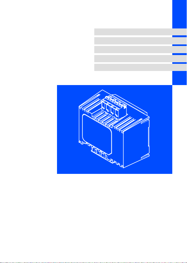
Motorbremsen−Ansteuerung
Motor brake control
Module de pilotage du frein de parking
Control de freno de motor
Comando freno motore
Page 2

Lesen Sie zuerst diese Anleitung und die Dokumentation zum Grundgerät,
bevor Sie mit den Arbeiten beginnen!
Beachten Sie die enthaltenen Sicherheitshinweise.
Please read these instructions and the documentation of the standard
device before you start working!
Observe the safety instructions given therein!
Lire le présent fascicule et la documentation relative à l’appareil de base
avant toute manipulation de l’équipement !
Respecter les consignes de sécurité fournies.
Lea estas instrucciones y la documentación del equipo básico antes de
empezar a trabajar.
Observe las instrucciones de seguridad indicadas.
Prima di iniziare qualsiasi intervento, leggere le presenti istruzioni e la
documentazione relativa al dispositivo di base.
Osservare le note di sicurezza.
Page 3
E94AZHN0025_003
Page 4
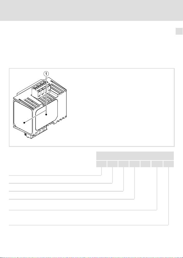
Lieferumfang
Pos. Beschreibung
Motorbremsen−Ansteuerung E94AZHN0026
Montageanleitung
Hutschienen−Adapter
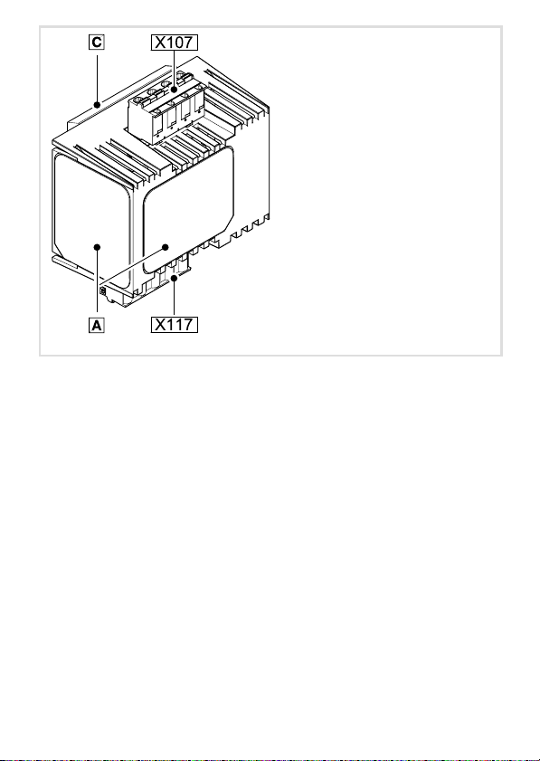
Elemente an der Motorbremsen−Ansteuerung
Pos. Beschreibung
Typenschild
X117 Steueranschluss
X107 Anschluss Versorgung und Bremse
© 2007 Lenze Drive Systems GmbH, Hans−Lenze−Straße 1, D−31855 Aerzen
Ohne besondere schriftliche Genehmigung von Lenze Drive Systems GmbH darf kein Teil dieser Dokumentation vervielfältigt oder Dritten zugänglich gemacht werden.
Wir haben alle Angaben in dieser Dokumentation mit größter Sorgfalt zusammengestellt und auf
Übereinstimmung mit der beschriebenen Hard− und Software geprüft. Trotzdem können wir Abweichungen nicht ganz ausschließen. Wir übernehmen keine juristische Verantwortung oder Haftung für
Schäden, die dadurch eventuell entstehen. Notwendige Korrekturen werden wir in die nachfolgenden
Auflagen einarbeiten.
4
EDK94AZHN26 DE/EN/FR/ES/IT 1.1
Page 5

Inhalt i
1 Sicherheitshinweise 7 . . . . . . . . . . . . . . . . . . . . . . . . . . . . . . . . . . . . . . . . . . . . . . . .
Definition der verwendeten Hinweise 7 . . . . . . . . . . . . . . . . . . . . . . . . . . . . . . . . .
Allgemeine Sicherheits− und Anwendungshinweise 9 . . . . . . . . . . . . . . . . . . . . . .
Sicherheitshinweise für die Installation nach UL oder UR 10 . . . . . . . . . . . . . . . . . .
2 Technische Daten 11 . . . . . . . . . . . . . . . . . . . . . . . . . . . . . . . . . . . . . . . . . . . . . . . . . .
Allgemeine Daten und Einsatzbedingungen 11 . . . . . . . . . . . . . . . . . . . . . . . . . . . .
Bemessungsdaten 15 . . . . . . . . . . . . . . . . . . . . . . . . . . . . . . . . . . . . . . . . . . . . . . . . . .
Mechanische Daten 17 . . . . . . . . . . . . . . . . . . . . . . . . . . . . . . . . . . . . . . . . . . . . . . . .
3 Mechanische Installation 18 . . . . . . . . . . . . . . . . . . . . . . . . . . . . . . . . . . . . . . . . . . . .
4 Elektrische Installation 19 . . . . . . . . . . . . . . . . . . . . . . . . . . . . . . . . . . . . . . . . . . . . . .
Wichtige Hinweise 19 . . . . . . . . . . . . . . . . . . . . . . . . . . . . . . . . . . . . . . . . . . . . . . . . .
Anschlussdaten 20 . . . . . . . . . . . . . . . . . . . . . . . . . . . . . . . . . . . . . . . . . . . . . . . . . . . .
Verdrahtungsbeispiel 22 . . . . . . . . . . . . . . . . . . . . . . . . . . . . . . . . . . . . . . . . . . . . . . .
EDK94AZHN26 DE/EN/FR/ES/IT 1.1
5
Page 6

i Dokumenthistorie
Materialnummer Version Beschreibung
13211685 1.0 08/2007 TD15 Erstausgabe
.8%R 1.1 12/2007 TD15 Korrektur der Beschriftung an Klemme X107
0Abb. 0Tab. 0
Tipp!
Aktuelle Dokumentationen und Software−Updates zu Lenze Produkten finden
Sie im Internet jeweils im Bereich "Services & Downloads" unter
http://www.Lenze.com
6
EDK94AZHN26 DE/EN/FR/ES/IT 1.1
Page 7
Definition der verwendeten Hinweise
1 Sicherheitshinweise
Definition der verwendeten Hinweise
Um auf Gefahren und wichtige Informationen hinzuweisen, werden in dieser Dokumentation folgende Piktogramme und Signalwörter verwendet:
Sicherheitshinweise
Aufbau der Sicherheitshinweise:
Gefahr!
(kennzeichnet die Art und die Schwere der Gefahr)
Hinweistext
(beschreibt die Gefahr und gibt Hinweise, wie sie vermieden werden kann)
Piktogramm und Signalwort Bedeutung
Gefahr von Personenschäden durch gefährliche elektrische
Spannung
Sicherheitshinweise
Gefahr!
Gefahr!
Stop!
Anwendungshinweise
Piktogramm und Signalwort Bedeutung
Hinweis auf eine unmittelbar drohende Gefahr, die den Tod
oder schwere Verletzungen zur Folge haben kann, wenn
nicht die entsprechenden Maßnahmen getroffen werden.
Gefahr von Personenschäden durch eine allgemeine Gefahrenquelle
Hinweis auf eine unmittelbar drohende Gefahr, die den Tod
oder schwere Verletzungen zur Folge haben kann, wenn
nicht die entsprechenden Maßnahmen getroffen werden.
Gefahr von Sachschäden
Hinweis auf eine mögliche Gefahr, die Sachschäden zur
Folge haben kann, wenn nicht die entsprechenden Maßnahmen getroffen werden.
1
Hinweis!
Tipp!
EDK94AZHN26 DE/EN/FR/ES/IT 1.1
Wichtiger Hinweis für die störungsfreie Funktion
Nützlicher Tipp für die einfache Handhabung
Verweis auf andere Dokumentation
7
Page 8

1 Sicherheitshinweise
Definition der verwendeten Hinweise
Spezielle Sicherheitshinweise und Anwendungshinweise für UL und UR
Piktogramm und Signalwort Bedeutung
Sicherheitshinweis oder Anwendungshinweis für den Betrieb eines UL−approbierten Geräts in UL−approbierten Anla-
Warnings!
Warnings!
gen.
Möglicherweise wird das Antriebssystem nicht UL−gerecht
betrieben, wenn nicht die entsprechenden Maßnahmen
getroffen werden.
Sicherheitshinweis oder Anwendungshinweis für den Betrieb eines UR−approbierten Geräts in UL−approbierten Anlagen.
Möglicherweise wird das Antriebssystem nicht UL−gerecht
betrieben, wenn nicht die entsprechenden Maßnahmen
getroffen werden.
8
EDK94AZHN26 DE/EN/FR/ES/IT 1.1
Page 9

Allgemeine Sicherheits− und Anwendungshinweise
Allgemeine Sicherheits− und Anwendungshinweise
Gefahr!
Sicherheitshinweise
Gefährliche elektrische Spannung!
An den Anschlüssen des Bremsenschalters können gefährliche elektrische
Spannungen anliegen.
Mögliche Folgen:
ƒ Tod oder schwerste Verletzungen beim Berühren der Anschlussklemmen.
Schutzmaßnahmen:
ƒ Vor allen Arbeiten das Grundgerät und den Bremsenschalter vom Netz
trennen.
ƒ Alle Leistungsklemmen auf Spannungsfreiheit prüfen.
Stop!
Die Motorbremsen−Ansteuerung beinhaltet einen elektronischen Schalter, der
eine Motorhaltebremse ansteuern kann.
An die Motorbremsen−Ansteuerung dürfen nur Motorhaltebremsen
angeschlossen werden, die den in den Technischen Daten genannten
zulässigen Daten entsprechen.
Werden die in den Technischen Daten genannten zulässigen Werte nicht
eingehalten:
ƒ kann die Motorbremsen−Ansteuerung zerstört werden.
ƒ ist ein sicherer Betrieb der Motorhaltebremse nicht gewährleistet.
Beachten Sie weitere Hinweise in der Dokumentation zum Grundgerät!
1
EDK94AZHN26 DE/EN/FR/ES/IT 1.1
9
Page 10

1 Sicherheitshinweise
Sicherheitshinweise für die Installation nach UL oder UR
Sicherheitshinweise für die Installation nach UL oder U
Warnings!
ƒ Use H, K5 or CC fuses.
ƒ Voltage of the fuses must at least be suitable with the input voltage.
ƒ Use 60/75 °C wire only.
ƒ Maximum surrounding air temperature: 55 °C with derating.
ƒ Load at "Brake Output" is provided for "dc pilot duty".
ƒ For use in a pollution degree 2 environment.
R
10
EDK94AZHN26 DE/EN/FR/ES/IT 1.1
Page 11
Allgemeine Daten und Einsatzbedingungen
Technische Daten
2 Technische Daten
Allgemeine Daten und Einsatzbedingungen
Gültigkeit
Diese Anleitung ist gültig für
ƒ Motorbremsen−Ansteuerung, Typ E94AZHN0026, Version HW: 1A
Identifikation
2
E94AZHN0025_003i
Typenschlüssel
Produktreihe
Gerätegeneration
Zubehör
Typ Motorbremsen−Ansteuerung
Bemessungsstrom
002 = 0.75 A
Spannungsklasse
5 = 205 V DC
6 = 180 V DC
EDK94AZHN26 DE/EN/FR/ES/IT 1.1
E94 A Z H N xxx x
11
Page 12

2 Technische Daten
Allgemeine Daten und Einsatzbedingungen
Einsetzbarkeit
Diese Komponente ist mit allen Produkten einsetzbar, die den Technischen Daten entsprechen.
12
EDK94AZHN26 DE/EN/FR/ES/IT 1.1
Page 13
Allgemeine Daten und Einsatzbedingungen
Technische Daten
Allgemeine Daten
Konformität und Approbation
Konformität
CE
Approbation
UR UL 508C Industrial Control Equipment Recognised
Personenschutz und Geräteschutz
Schutzart EN 60529
Schutzmaßnahmen Gegen Kurzschluss
73/23/EWG Niederspannungsrichtlinie
(File No. E132659) für USA
IP00
2
Montagebedingungen
Einbauort
Einbaulage Vertikal
Einbaufreiräume
oberhalb/unterhalb
seitlich seitlich ohne Abstand anreihbar
EMV
Störaussendung EN 61800−3
Störfestigkeit EN 61800−3
EDK94AZHN26 DE/EN/FR/ES/IT 1.1
im Schaltschrank
³ 25 mm
Leitungsgeführt, Kategorie C2.
Burst auf Netzleitung: 2 kV/5 kHz
Burst auf Steuerleitung: 2 kV/5 kHz
Surge auf Netzleitung:
1 kV (1,2 ms/50 ms;
Phase − Phase)
2 kV (1,2 ms/50 ms;
Phase − PE)
13
Page 14
2 Technische Daten
Allgemeine Daten und Einsatzbedingungen
Einsatzbedingungen
Umweltbedingungen
Klima
Lagerung IEC/EN 60721−3−1 1K3 (−25 ... +60 °C)
Transport IEC/EN 60721−3−2 2K3 (−25 ... +70 °C)
Betrieb IEC/EN 60721−3−3 3K3 (−10 ... +55 °C)
Aufstellhöhe 0 ... 4000 m üNN
Verschmutzung EN 61800−5−1 Verschmutzungsgrad 2
Rüttelfestigkeit (9,81 m/s
Transport
2
= 1 g)
IEC/EN 60721−3−2 2M2
EN 61800−2
Betrieb
Germanischer
Lloyd
EN 600068−2−6
1000 ... 4000 m üNN: Stromreduzierung 5 %/1000 m
2 ... 9 Hz: Amplitude 3.5 mm
10 ... 200 Hz: beschleunigungsfest bis 10 m/s
200 ... 500 Hz: beschleunigungsfest bis 15 m/s
5 ... 13,2 Hz: Amplitude ±1 mm
13.2 ... 100 Hz: beschleunigungsfest bis 0.7 g
10 ... 57 Hz: Amplitude 0.075 mm
57 ... 150 Hz: beschleunigungsfest bis 10 m/s
2
2
2
14
EDK94AZHN26 DE/EN/FR/ES/IT 1.1
Page 15
Technische Daten
Bemessungsdaten
Bemessungsdaten
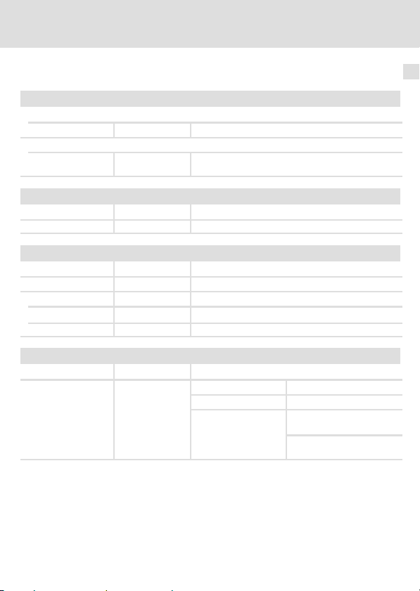
Eingangsdaten
Spannung Frequenz Strom [A]
Typ [V] [Hz]
E94AZHN0026 400/500 50/60 0.75/0.75 0.61/0.61 1
Temperatur im Schaltschrank
Ausgangsdaten
Spannung Frequenz Strom [A]
Typ [V] [Hz]
E94AZHN0026 180/225 0 (DC) 0.75/0.75 0.61/0.61 1
Temperatur im Schaltschrank
Bereich Werte
Eingangsspannung AC 400 V (320 ... 550 V), 45 ... 65 Hz
Ausgangsspannung DC 180 V bei Netzspannung AC 400 V
Bremsenstrom 0.1 ... 0.61 A
Leitungsschutz Empfehlung: 5 A, Auslösecharakteristik "B" oder "C"
Steuereingang DI
Meldeausgang DO
Steuerspannung
Steuerstrom
Schutzfunktion Verpolungssicher bis DC 60 V
Maximal anschließbarer
Leitungsquerschnitt
Maximale Leitungslänge 150 m
DC 24 V, SPS−Pegel
HIGH
LOW
Eingang 5 ... 10 mA
Ausgang 5 ... 50 mA
2,5 mm
AWG 12
2
DC +15 ... 30 V
DC 0 ... +3 V
bis +45 °C bis +55 °C
bis +45 °C bis +55 °C
Phasen-
zahl
Phasen-
zahl
2
EDK94AZHN26 DE/EN/FR/ES/IT 1.1
15
Page 16
2 Technische Daten
Bemessungsdaten
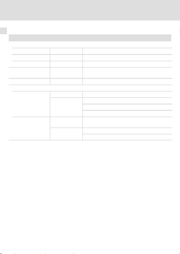
Zulässige Schalthäufigkeiten
Empfohlene Bremse Leistung Spule: Spannung DC 180 V Zulässige Schalthäufigkeit
Typ P [W] L [H] I [A] (20 °C) [1/min]
BFK457−06E
BFK458−06E
BFK457−08E
BFK458−08E
BFK457−10E
BFK458−10E
BFK457−12E
BFK458−12E
BFK457−14E
BFK458−14E
BFK457−16E
BFK458−16E
BFK457−18E
BFK458−18E
BFK457−20E
BFK458−20E
BFK457−25E
BFK458−25E
20
25 50 0,14 60
30 69 0,17 60
40 81 0,22 40
50 78 0,28 30
55 102 0,31 20
85 77 0,47 10
100 92 0,56 8
110 102 0,61 6
60 0,11 60
16
EDK94AZHN26 DE/EN/FR/ES/IT 1.1
Page 17
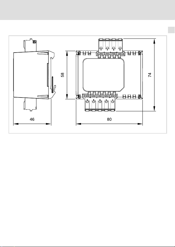
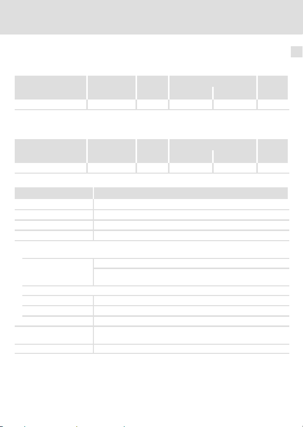
Mechanische Daten
Alle Maße in Millimeter.
Technische Daten
Mechanische Daten
E94AZHN0025_005
2
EDK94AZHN26 DE/EN/FR/ES/IT 1.1
17
Page 18

3 Mechanische Installation
3 Mechanische Installation
Montageschritte
Hutschienen−Montage
1. Motorbremsen−Ansteuerung mit dem Hutschienen−Adapter an der Hutschiene
unten ansetzen.
2. Motorbremsen−Ansteuerung gegen die Federkraft am oberen Hutschienenrand
einrasten.
3. Motorbremsen−Ansteuerung auf festen Sitz kontrollieren.
18
EDK94AZHN26 DE/EN/FR/ES/IT 1.1
Page 19

Elektrische Installation
Wichtige Hinweise
4 Elektrische Installation
Wichtige Hinweise
Bei der Installation die Hinweise aus der Dokumentation zum Grundgerät
beachten!
Stop!
Anforderungen an die Bremsenleitung (Anschluss BD1/BD2):
ƒ Ist die Bremsenleitung Bestandteil der Motorleitung, so ist sie unbedingt
geschirmt ausführen.
– Der Betrieb mit ungeschirmten Bremsenleitungen kann die
Motorbremsen−Ansteuerung zerstören.
– Wir empfehlen die Verwendung von Lenze−Systemleitungen
(Motorleitung mit separat geschirmten Zusatzadern).
– Schirm beidseitig auf PE legen.
ƒ Achten Sie bei einer Permanentmagnet−Haltebremse auf korrekte Polung
der Bremsenleitung.
– Sind die Anschlüsse vertauscht, lüftet die Bremse nicht. Da der Motor
gegen die geschlossene Bremse läuft, kann die Bremse zerstört werden.
Hinweis!
Der Zustand der Versorgung kann über den Fehlerkanal zum Grundgerät
gemeldet werden. Weitere Informationen entnehmen Sie der Dokumentation
zum Grundgerät.
4
EDK94AZHN26 DE/EN/FR/ES/IT 1.1
19
Page 20
4 Elektrische Installation
Anschlussdaten
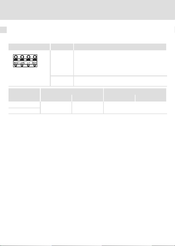
Anschlussdaten
Anschluss Motorhaltebremse
Klemme X107 Beschriftung Beschreibung
Anschluss der Motorhaltebremse:
BD1
BD2
SSP94A6107
Klemmendaten
flexibel
mit Aderendhülse
Abisolierlänge bzw. Kontaktlänge: 8 mm
L1
L2/N
[mm2] [AWG] [Nm] [lb−in]
0.5 ... 2.5
+ (Lenze: WH)
− (Lenze: BN)
E94AZHN0026: 180 V DC, max. 0,75 A
Auf richtige Polung achten!
Versorgungsspannung der Motorhaltebremse
Leiterquerschnitt Anzugsmoment
20 ... 12 Federkraftklemme
20
EDK94AZHN26 DE/EN/FR/ES/IT 1.1
Page 21
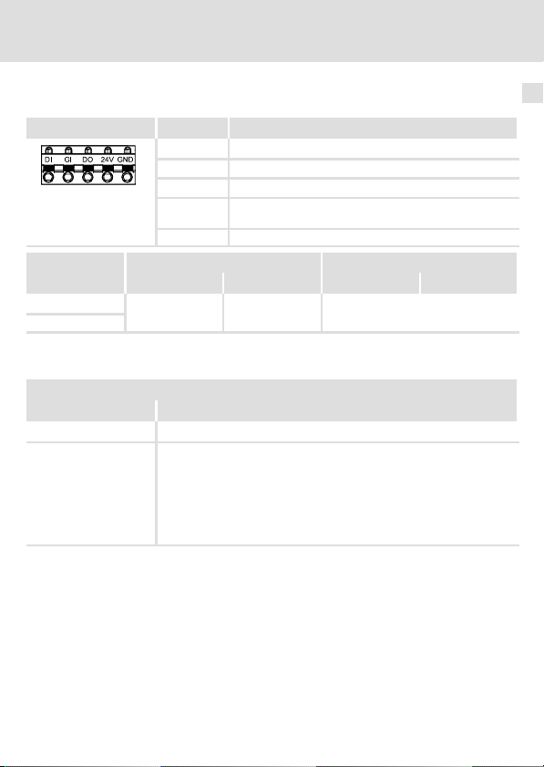
Steueranschluss
Klemme X117 Beschriftung Beschreibung
DI Digitaleingang
GI GND Digital In
DO Meldeausgang
24V 24−V−Versorgung durch ein sicher getrenntes Netzteil
SSP94A6117
Klemmendaten
flexibel
mit Aderendhülse
Abisolierlänge bzw. Kontaktlänge: 8 mm
Digitalausgang DO
Zustand Beschreibung
HIGH keine Fehler
LOW Fehler
GND GND Digital out
[mm2] [AWG] [Nm] [lb−in]
0.5 ... 2.5
l Versorgungsspannung Motorhaltebremse fehlt
l Motorhaltebremse nicht angeschlossen
l Bremsenleitung defekt
l Versorgungsspannung Motorbremsen−Ansteuerung fehlt
(SELV/PELV)
Leiterquerschnitt Anzugsmoment
20 ... 12 Federkraftklemme
– Drahtbruch
– Kurzschluss
Elektrische Installation
Anschlussdaten
4
EDK94AZHN26 DE/EN/FR/ES/IT 1.1
21
Page 22
4 Elektrische Installation
Verdrahtungsbeispiel
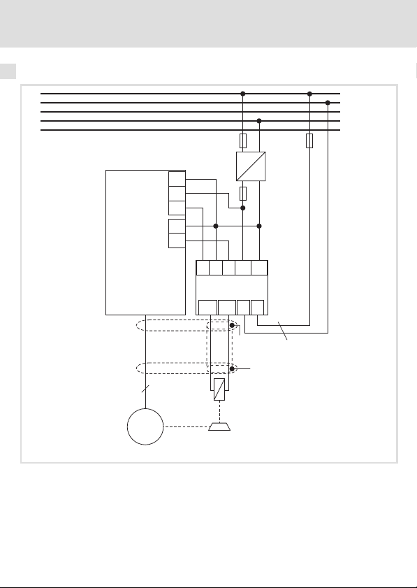
Verdrahtungsbeispiel
L1
L2
L3
N
PE
X4
...
E94AxxExxx4
X5
GO
24O
DOx
GI
DIx
~
+
DI GI
DO
24V
E94AZHN0026
L2/N
BD1 BD2
GND
L1
F10
=
-
X117
X107
"
"
3
M
3~
F10 Leitungsschutz der Motorhaltebremse
Bei der Auslegung der Sicherung die Normen des Leitungsschutzes beachten!
E94A... Komponenten der Reihe 9400
HF−Schirmabschluss durch großflächige PE−Anbindung.
22
≤
2.5 mm²
E94AZH017−B
EDK94AZHN26 DE/EN/FR/ES/IT 1.1
Page 23

Elektrische Installation
Verdrahtungsbeispiel
4
EDK94AZHN26 DE/EN/FR/ES/IT 1.1
23
Page 24
Scope of supply
Pos. Description
Motor brake control E94AZHN0026
Mounting Instructions
DIN rail adapter
Elements of the motor brake control
Pos. Description
Nameplate
X117 Control connection
X107 Connection of supply and brake
© 2007 Lenze Drive Systems GmbH, Hans−Lenze−Straße 1, D−31855 Aerzen
No part of this documentation may be reproduced or made accessible to third parties without written
consent by Lenze Drive Systems GmbH.
All information given in this documentation has been selected carefully and complies with the
hardware and software described. Nevertheless, discrepancies cannot be ruled out. We do not take any
responsibility or liability for any damage that may occur. Necessary corrections will be included in
subsequent editions.
24
EDK94AZHN26 DE/EN/FR/ES/IT 1.1
Page 25

Contents i
1 Safety instructions 27 . . . . . . . . . . . . . . . . . . . . . . . . . . . . . . . . . . . . . . . . . . . . . . . . .
Definition of notes used 27 . . . . . . . . . . . . . . . . . . . . . . . . . . . . . . . . . . . . . . . . . . . . .
General safety and application notes 29 . . . . . . . . . . . . . . . . . . . . . . . . . . . . . . . . . .
Safety instructions for the installation according to UL or UR 30 . . . . . . . . . . . . . . .
2 Technical data 31 . . . . . . . . . . . . . . . . . . . . . . . . . . . . . . . . . . . . . . . . . . . . . . . . . . . . .
General data and operating conditions 31 . . . . . . . . . . . . . . . . . . . . . . . . . . . . . . . . .
Rated data 35 . . . . . . . . . . . . . . . . . . . . . . . . . . . . . . . . . . . . . . . . . . . . . . . . . . . . . . . .
Mechanical data 37 . . . . . . . . . . . . . . . . . . . . . . . . . . . . . . . . . . . . . . . . . . . . . . . . . . .
3 Mechanical installation 38 . . . . . . . . . . . . . . . . . . . . . . . . . . . . . . . . . . . . . . . . . . . . .
4 Electrical installation 39 . . . . . . . . . . . . . . . . . . . . . . . . . . . . . . . . . . . . . . . . . . . . . . .
Important notes 39 . . . . . . . . . . . . . . . . . . . . . . . . . . . . . . . . . . . . . . . . . . . . . . . . . . .
Connection data 40 . . . . . . . . . . . . . . . . . . . . . . . . . . . . . . . . . . . . . . . . . . . . . . . . . . .
Wiring example 42 . . . . . . . . . . . . . . . . . . . . . . . . . . . . . . . . . . . . . . . . . . . . . . . . . . . .
EDK94AZHN26 DE/EN/FR/ES/IT 1.1
25
Page 26

i Document history
Material number Version Description
13211685 1.0 08/2007 TD15 First edition
.8%R 1.1 12/2007 TD15 Correction of X107 terminal labelling
0Fig. 0Tab. 0
Tip!
Current documentation and software updates concerning Lenze products can
be found on the Internet in the "Services & Downloads" area under
http://www.Lenze.com
26
EDK94AZHN26 DE/EN/FR/ES/IT 1.1
Page 27
Safety instructions
Definition of notes used
1 Safety instructions
Definition of notes used
The following pictographs and signal words are used in this documentation to indicate
dangers and important information:
Safety instructions
Structure of safety instructions:
Danger!
(characterises the type and severity of danger)
Note
(describes the danger and gives information about how to prevent dangerous
situations)
Pictograph and signal word Meaning
Danger of personal injury through dangerous electrical
voltage.
Danger!
Danger!
Stop!
Application notes
Pictograph and signal word Meaning
Reference to an imminent danger that may result in death
or serious personal injury if the corresponding measures are
not taken.
Danger of personal injury through a general source of
danger.
Reference to an imminent danger that may result in death
or serious personal injury if the corresponding measures are
not taken.
Danger of property damage.
Reference to a possible danger that may result in property
damage if the corresponding measures are not taken.
1
Note!
Tip!
EDK94AZHN26 DE/EN/FR/ES/IT 1.1
Important note to ensure troublefree operation
Useful tip for simple handling
Reference to another documentation
27
Page 28
1 Safety instructions
Definition of notes used
Special safety instructions and application notes for UL and UR
Pictograph and signal word Meaning
Safety or application note for the operation of a
Warnings!
Warnings!
UL−approved device in UL−approved systems.
Possibly the drive system is not operated in compliance
with UL if the corresponding measures are not taken.
Safety or application note for the operation of a
UR−approved device in UL−approved systems.
Possibly the drive system is not operated in compliance
with UL if the corresponding measures are not taken.
28
EDK94AZHN26 DE/EN/FR/ES/IT 1.1
Page 29

General safety and application notes
General safety and application notes
Danger!
Safety instructions
Dangerous electrical voltage!
Dangerous electrical voltages may be applied to the connections of the brake
switch.
Possible consequences:
ƒ Death or severe injuries when touching the terminals.
Protective measures:
ƒ Disconnect the standard device and the brake switch from the mains
before carrying out any operations.
ƒ Check that all power terminals are deenergised.
Stop!
The motor brake control includes an electronic switch which can control a
motor holding brake.
The motor brake control module may only be connected to holding brakes
which correspond to the permissible data specified in the technical data.
If the permissible values specified in the technical data are not complied with:
ƒ The motor brake control module can be destroyed.
ƒ A safe operation of the motor holding brake cannot be guaranteed.
Further notes in the documentation of the standard device must be observed!
1
EDK94AZHN26 DE/EN/FR/ES/IT 1.1
29
Page 30

1 Safety instructions
Safety instructions for the installation according to UL or UR
Safety instructions for the installation according to UL or U
Warnings!
ƒ Use H, K5 or CC fuses.
ƒ Voltage of the fuses must at least be suitable with the input voltage.
ƒ Use 60/75 °C wire only.
ƒ Maximum surrounding air temperature: 55 °C with derating.
ƒ Load at "Brake Output" is provided for "dc pilot duty".
ƒ For use in a pollution degree 2 environment.
R
30
EDK94AZHN26 DE/EN/FR/ES/IT 1.1
Page 31

General data and operating conditions
2 Technical data
General data and operating conditions
Validity
These instructions are valid for
ƒ Motor brake control, type E94AZHN0026, version HW: 1A
Identification
Technical data
E94AZHN0025_003i
2
Type code
Product series
Accessories
Motor brake control type
Rated current
002 = 0.75 A
Voltage class
5 = 205 V DC
6 = 180 V DC
EDK94AZHN26 DE/EN/FR/ES/IT 1.1
E94 A Z H N xxx x
31
Page 32

2 Technical data
General data and operating conditions
Application range
This component can be used together with all products that correspond to the technical
data.
32
EDK94AZHN26 DE/EN/FR/ES/IT 1.1
Page 33

General data and operating conditions
Technical data
General data
Conformity and approval
Conformity
CE
Approval
UR UL 508C Industrial Control Equipment Recognised
Protection of persons and equipment
Enclosure EN 60529
Protective measures Against short circuit
73/23/EEC Low−Voltage Directive
(file no. E132659) for USA
IP00
2
Mounting conditions
Mounting place
Mounting position Vertically
Mounting clearances
Above/below
To the sides Side−by−side mounting without clearance
EMC
Noise emission EN 61800−3
Noise immunity EN 61800−3
EDK94AZHN26 DE/EN/FR/ES/IT 1.1
In the control cabinet
³ 25 mm
Conducted, category C2.
Burst on mains cable: 2 kV/5 kHz
Burst on control cable: 2 kV/5 kHz
Surge on mains cable:
1 kV (1.2 ms/50 ms;
phase − phase)
2 kV (1.2 ms/50 ms;
phase − PE)
33
Page 34

2 Technical data
General data and operating conditions
Operating conditions
Environmental conditions
Climate
Storage IEC/EN 60721−3−1 1K3 (−25 ... +60 °C)
Transport IEC/EN 60721−3−2 2K3 (−25 ... +70 °C)
Operation IEC/EN 60721−3−3 3K3 (−10 ... +55 °C)
Site altitude 0 ... 4000 m amsl
Pollution EN 61800−5−1 Pollution degree 2
Vibration resistance (9.81 m/s
Transport
2
= 1 g)
IEC/EN 60721−3−2 2M2
EN 61800−2
Operation
Germanischer
Lloyd
EN 600068−2−6
1000 ... 4000 m amsl: current derating of 5 %/1000 m
2 ... 9 Hz: amplitude 3.5 mm
10 ... 200 Hz: acceleration resistant up to 10 m/s
200 ... 500 Hz: acceleration resistant up to 15 m/s
5 ... 13.2 Hz: amplitude ±1 mm
13.2 ... 100 Hz: acceleration resistant up to 0.7 g
10 ... 57 Hz: amplitude 0.075 mm
57 ... 150 Hz: acceleration resistant up to 10 m/s
2
2
2
34
EDK94AZHN26 DE/EN/FR/ES/IT 1.1
Page 35

Technical data
Rated data
Rated data
Input data
Voltage Frequency Current [A]
Type [V] [Hz] max. +45 °Cmax. +55 °C
E94AZHN0026 400/500 50/60 0.75/0.75 0.61/0.61 1
Temperature in the control cabinet
Output data
Voltage Frequency Current [A]
Type [V] [Hz] max. +45 °Cmax. +55 °C
E94AZHN0026 180/225 0 (DC) 0.75/0.75 0.61/0.61 1
Temperature in the control cabinet
Area Values
Input voltage AC 400 V (320 ... 550 V), 45 ... 65 Hz
Output voltage DC 180 V With mains voltage of AC 400 V
Brake current 0.1 ... 0.61 A
Cable protection Recommendation: 5 A, tripping characteristic "B" or "C"
Control input DI
Signalling output DO
Control voltage
Control current
Protective function Protected against polarity reversal up to DC 60 V
Max. connectable cable
cross−section
Maximum cable length 150 m
DC 24 V, PLC level
HIGH
LOW
Input 5 ... 10 mA
Output 5 ... 50 mA
2.5 mm
AWG 12
2
DC +15 ... 30 V
DC 0 ... +3 V
Number
of
phases
Number
of
phases
2
EDK94AZHN26 DE/EN/FR/ES/IT 1.1
35
Page 36

2 Technical data
Rated data
Permissible operating frequencies
Recommended brake Power Coil: Voltage DC 180 V Permissible operating
Type P [W] L [H] I [A] (20 °C) [rpm]
BFK457−06E
BFK458−06E
BFK457−08E
BFK458−08E
BFK457−10E
BFK458−10E
BFK457−12E
BFK458−12E
BFK457−14E
BFK458−14E
BFK457−16E
BFK458−16E
BFK457−18E
BFK458−18E
BFK457−20E
BFK458−20E
BFK457−25E
BFK458−25E
20
25 50 0.14 60
30 69 0.17 60
40 81 0.22 40
50 78 0.28 30
55 102 0.31 20
85 77 0.47 10
100 92 0.56 8
110 102 0.61 6
60 0.11 60
frequency
36
EDK94AZHN26 DE/EN/FR/ES/IT 1.1
Page 37

Mechanical data
All dimensions in millimetres.
Technical data
Mechanical data
E94AZHN0025_005
2
EDK94AZHN26 DE/EN/FR/ES/IT 1.1
37
Page 38

3 Mechanical installation
3 Mechanical installation
Installation steps
DIN rail mounting
1. Position the motor brake control module with the DIN rail adapter at the bottom
of the DIN rail.
2. Let the motor brake control module snap into the upper DIN rail edge against the
resistance of the spring force.
3. Check that the motor brake control module is securely connected.
38
EDK94AZHN26 DE/EN/FR/ES/IT 1.1
Page 39

Electrical installation
Important notes
4 Electrical installation
Important notes
During installation the notes given in the documentation for the standard
device must be observed!
Stop!
Requirements on the brake cable (connection BD1/BD2):
ƒ If the brake cable is part of the motor cable, it must be shielded.
– An operation with unshielded brake cables can destroy the motor brake
control module.
– We recommend the use of Lenze system cables (motor cable with
separately shielded additional cores).
– Connect the shield to PE on both sides.
ƒ When using a permanent magnet holding brake, ensure the correct
polarity of the brake cable.
– If the terminals are reversed, the brake does not release. Since the motor
runs against the closed brake, the brake can be destroyed.
Note!
The supply status can be reported to the standard device via the error channel.
For further information, please refer to the documentation of the standard
device.
4
EDK94AZHN26 DE/EN/FR/ES/IT 1.1
39
Page 40

4 Electrical installation
Connection data
Connection data
Connection of the motor holding brake
Terminal X107 Labelling Description
Connection of the motor holding brake:
BD1
BD2
SSP94A6107
Terminal data
Flexible
With wire end
ferrule
Stripping length or contact length: 8 mm
L1
L2/N
Conductor cross−section Tightening torque
[mm2] [AWG] [Nm] [lb−in]
0.5 ... 2.5 20 ... 12 Spring terminal
+ (Lenze: WH)
− (Lenze: BN)
E94AZHN0026: 180 V DC, max. 0.75 A
Ensure correct polarity!
Supply voltage of the motor holding brake
40
EDK94AZHN26 DE/EN/FR/ES/IT 1.1
Page 41

Control connection
Terminal X117 Labelling Description
DI Digital input
GI GND digital in
DO Signalling output
24V 24−V supply by safely separated power supply unit
SSP94A6117
Terminal data
Flexible
With wire end
ferrule
Stripping length or contact length: 8 mm
Digital output DO
State Description
HIGH No fault
LOW Fault
GND GND digital out
Conductor cross−section Tightening torque
[mm2] [AWG] [Nm] [lb−in]
0.5 ... 2.5 20 ... 12 Spring terminal
l Supply voltage of the motor holding brake is missing
l Motor holding brake is not connected
l Brake cable is defective
l Supply voltage of the motor brake control is missing
(SELV/PELV)
– Open circuit
– Short circuit
Electrical installation
Connection data
4
EDK94AZHN26 DE/EN/FR/ES/IT 1.1
41
Page 42

4 Electrical installation
Wiring example
Wiring example
L1
L2
L3
N
PE
X4
...
E94AxxExxx4
X5
GO
24O
DOx
GI
DIx
~
+
DI GI
DO
24V
E94AZHN0026
L2/N
BD1 BD2
GND
L1
F10
=
-
X117
X107
3
M
3~
F10 Cable protection of the motor holding brake
Observe the cable protection standards for fuse dimensioning!
E94A... Components of the 9400 series
HF shield termination through large−surface PE connection
42
"
≤
2.5 mm²
"
E94AZH017−B
EDK94AZHN26 DE/EN/FR/ES/IT 1.1
Page 43

Electrical installation
Wiring example
4
EDK94AZHN26 DE/EN/FR/ES/IT 1.1
43
Page 44

Equipement livré
Pos. Description
Module de pilotage du frein de parking E94AZHN0026
Instructions de montage
Adaptateur rail DIN
Eléments du module de pilotage du frein de parking
Pos. Description
Plaque signalétique
X117 Raccordement de commande
X107 Raccordement de l’alimentation et du frein
© 2007 Lenze Drive Systems GmbH, Hans−Lenze−Straße 1, D−31855 Aerzen
Toute représentation ou reproduction, en tout ou en partie et par quelque procédé que ce soit, est
illicite sans l’autorisation écrite préalable de Lenze Drive Systems GmbH.
Les données figurant dans le présent fascicule ont été établies avec le plus grand soin et leur conformité
avec le matériel et le logiciel décrits a été vérifiée. Des divergences ne peuvent toutefois pas être
totalement exclues. Nous ne saurions être tenus responsables pour tout dommage qui pourrait
éventuellement en découler. Les corrections nécessaires seront intégrées dans les éditions suivantes.
44
EDK94AZHN26 DE/EN/FR/ES/IT 1.1
Page 45

Sommaire i
1 Consignes de sécurité 47 . . . . . . . . . . . . . . . . . . . . . . . . . . . . . . . . . . . . . . . . . . . . . . .
Définition des conventions utilisées 47 . . . . . . . . . . . . . . . . . . . . . . . . . . . . . . . . . . .
Instructions générales de sécurité et d’utilisation 49 . . . . . . . . . . . . . . . . . . . . . . . .
Consignes de sécurité pour l’installation selon UL ou UR 50 . . . . . . . . . . . . . . . . . .
2 Spécifications techniques 51 . . . . . . . . . . . . . . . . . . . . . . . . . . . . . . . . . . . . . . . . . . .
Caractéristiques générales et conditions d’utilisation 51 . . . . . . . . . . . . . . . . . . . . .
Caractéristiques nominales 55 . . . . . . . . . . . . . . . . . . . . . . . . . . . . . . . . . . . . . . . . . .
Caractéristiques mécaniques 57 . . . . . . . . . . . . . . . . . . . . . . . . . . . . . . . . . . . . . . . . .
3 Installation mécanique 58 . . . . . . . . . . . . . . . . . . . . . . . . . . . . . . . . . . . . . . . . . . . . . .
4 Installation électrique 59 . . . . . . . . . . . . . . . . . . . . . . . . . . . . . . . . . . . . . . . . . . . . . . .
Remarques importantes 59 . . . . . . . . . . . . . . . . . . . . . . . . . . . . . . . . . . . . . . . . . . . . .
Données de raccordement 60 . . . . . . . . . . . . . . . . . . . . . . . . . . . . . . . . . . . . . . . . . . .
Exemple de câblage 62 . . . . . . . . . . . . . . . . . . . . . . . . . . . . . . . . . . . . . . . . . . . . . . . .
EDK94AZHN26 DE/EN/FR/ES/IT 1.1
45
Page 46

i Historique du document
Numéro de matériel Version Description
13211685 1.0 08/2007 TD15 Première édition
.8%R 1.1 12/2007 TD15 Correction de l’inscription sur le bornier X107
0Fig. 0Tab. 0
Conseil !
Les mises à jour de logiciels et les documentations récentes relatives aux
produits Lenze sont disponibles dans la zone "Téléchargements" du site
Internet :
http://www.Lenze.com
46
EDK94AZHN26 DE/EN/FR/ES/IT 1.1
Page 47

Consignes de sécurité
Définition des conventions utilisées
1 Consignes de sécurité
Définition des conventions utilisées
Pour indiquer des risques et des informations importantes, la présente documentation
utilise les mots et symboles suivants :
Consignes de sécurité
Présentation des consignes de sécurité
Danger !
(Le pictogramme indique le type de risque.)
Explication
(L’explication décrit le risque et les moyens de l’éviter.)
Pictogramme et mot associé Explication
Situation dangereuse pour les personnes en raison d’une
tension électrique élevée
Danger !
Danger !
Stop !
Indication d’un danger imminent qui peut avoir pour
conséquences des blessures mortelles ou très graves en cas
de non−respect des consignes de sécurité correspondantes
Situation dangereuse pour les personnes en raison d’un
danger d’ordre général
Indication d’un danger imminent qui peut avoir pour
conséquences des blessures mortelles ou très graves en cas
de non−respect des consignes de sécurité correspondantes
Risques de dégâts matériels
Indication d’un risque potentiel qui peut avoir pour
conséquences des dégâts matériels en cas de non−respect
des consignes de sécurité correspondantes
1
EDK94AZHN26 DE/EN/FR/ES/IT 1.1
47
Page 48

1 Consignes de sécurité
Définition des conventions utilisées
Consignes d’utilisation
Pictogramme et mot associé Explication
Remarque
importante !
Conseil !
Consignes de sécurité et d’utilisation spécifiques selon UL et UR
Pictogramme et mot associé Signification
Warnings !
Warnings !
Remarque importante pour assurer un fonctionnement
correct
Conseil utile pour faciliter la mise en oeuvre
Référence à une autre documentation
Consigne de sécurité ou d’utilisation pour le
fonctionnement d’un appareil homologué UL dans des
installations homologuées UL
Le système d’entraînement risque de ne pas être utilisé
selon les directives UL si des mesures correspondantes ne
sont pas prévues.
Consigne de sécurité ou d’utilisation pour le
fonctionnement d’un appareil homologué UR dans des
installations homologuées UL
Le système d’entraînement risque de ne pas être utilisé
selon les directives UL si des mesures correspondantes ne
sont pas prévues.
48
EDK94AZHN26 DE/EN/FR/ES/IT 1.1
Page 49

Instructions générales de sécurité et d’utilisation
Instructions générales de sécurité et d’utilisation
Danger !
Consignes de sécurité
Tension électrique dangereuse !
Des tensions électriques dangereuses peuvent circuler dans les raccordements
du contacteur de frein.
Risques encourus :
ƒ Mort ou blessures très graves en cas de contact accidentel avec les bornes
de raccordement.
Mesures de protection :
ƒ Couper l’appareil de base et le contacteur de frein du réseau avant tous
travaux.
ƒ S’assurer que toutes les bornes de puissance sont hors tension.
Stop !
Le module de pilotage du frein de parking comprend un interrupteur
électronique permettant de piloter un frein de parking.
Seuls des freins de parking respectant les données indiquées dans les
spécifications techniques peuvent être raccordés au module de pilotage du
frein de parking.
Si les valeurs indiquées dans les spécifications techniques ne sont pas
respectées
ƒ le module de pilotage du frein de parking risque d’être détruit,
ƒ le fonctionnement sûr du frein de parking n’est pas garanti.
Tenir compte des indications contenues dans la documentation de l’appareil
de base !
1
EDK94AZHN26 DE/EN/FR/ES/IT 1.1
49
Page 50

1 Consignes de sécurité
Consignes de sécurité pour l’installation selon UL ou UR
Consignes de sécurité pour l’installation selon UL ou U
Warnings !
ƒ Use H, K5 or CC fuses.
ƒ Voltage of the fuses must at least be suitable with the input voltage.
ƒ Use 60/75 °C wire only.
ƒ Maximum surrounding air temperature: 55 °C with derating.
ƒ Load at "Brake Output" is provided for "dc pilot duty".
ƒ For use in a pollution degree 2 environment.
R
50
EDK94AZHN26 DE/EN/FR/ES/IT 1.1
Page 51

Caractéristiques générales et conditions d’utilisation
Spécifications techniques
2 Spécifications techniques
Caractéristiques générales et conditions d’utilisation
Validité
Le présent document s’applique aux produits suivants :
ƒ aux modules de pilotage du frein de parking, type E94AZHN0026,
version matérielle : 1A
Identification
2
E94AZHN0025_003i
Codification des types
Série d’appareils
Génération d’appareils
Accessoires
Type : module de pilotage du frein de parking
Courant nominal
002 = 0,75 A
Classe de tension
5 = 205 V CC
6 = 180 V CC
EDK94AZHN26 DE/EN/FR/ES/IT 1.1
E94 A Z H N xxx x
51
Page 52

2 Spécifications techniques
Caractéristiques générales et conditions d’utilisation
Utilisation
Ces composants peuvent être utilisés avec tous les produits respectant les spécifications
techniques.
52
EDK94AZHN26 DE/EN/FR/ES/IT 1.1
Page 53

Caractéristiques générales et conditions d’utilisation
Spécifications techniques
Caractéristiques générales
Conformité et homologation
Conformité
CE
Homologation
UR UL 508C Industrial Control Equipment Recognised
Protection des personnes et protection d’appareil
Indice de protection EN 60529
Mesures de protection Contre les courts−circuits
73/23/CEE Directive Basse Tension
(File No. E132659) pour les Etas−Unis
IP00
2
Conditions de montage
Emplacement de
montage
Position de montage Verticale
Espacements de
montage
Au−dessus/en
dessous de l’appareil
Sur les côtés de
l’appareil
CEM
Perturbations
radioélectriques :
émission
Protection contre les
parasites
EDK94AZHN26 DE/EN/FR/ES/IT 1.1
EN 61800−3
EN 61800−3
Dans l’armoire électrique
³ 25 mm
Juxtaposition possible (espace nul)
Conduites par câbles, catégorie C2.
Transitoires rapides en
salves : câble réseau
Transitoires rapides en
salves : câble de
commande
Ondes de chocs : câble
réseau
2 kV/5 kHz
2 kV/5 kHz
1 kV (1,2 ms/50 ms ;
phase − phase)
2 kV (1,2 ms/50 ms ;
phase − PE)
53
Page 54

2 Spécifications techniques
Caractéristiques générales et conditions d’utilisation
Conditions d’utilisation
Conditions climatiques
Température ambiante
Stockage CEI/EN 60721−3−1 Classe 1K3 (−25 ... +60 °C)
Transport CEI/EN 60721−3−2 Classe 2K3 (−25 ... +70 °C)
Fonctionnement CEI/EN 60721−3−3 Classe 3K3 (−10 ... +55 °C)
Altitude d’implantation 0 ... 4000 m au−dessus du niveau de la mer
Pollution ambiante
admissible
Résistance aux chocs (9,81 m/s
Transport
EN 61800−5−1 Degré de pollution 2
2
= 1 g)
CEI/EN 60721−3−2 2M2
EN 61800−2
Fonctionnement
Germanischer
Lloyd
EN 600068−2−6
1000 ... 4000 m au−dessus du niveau de la mer :
réduction de courant de 5 %/1000 m
2 ... 9 Hz : amplitude de 3,5 mm
10 ... 200 Hz : résistant à l’accélération jusqu’à 10 m/s
200 ... 500 Hz : résistant à l’accélération jusqu’à
2
15 m/s
5 ... 13,2 Hz : amplitude de ±1 mm
13.2 ... 100 Hz : résistant à l’accélération jusqu’à 0,7 g
10 ... 57 Hz : amplitude de 0,075 mm
57 ... 150 Hz : résistant à l’accélération jusqu’à 10 m/s
2
2
54
EDK94AZHN26 DE/EN/FR/ES/IT 1.1
Page 55

Spécifications techniques
Caractéristiques nominales
Caractéristiques nominales
Données d’entrée
Tension Fréquence Courant [A]
Type [V] [Hz] +45 °C maxi+55 °C maxi
E94AZHN0026 400/500 50/60 0,75/0,75 0,61/0,61 1
Température dans l’armoire électrique
Données de sortie
Tension Fréquence Courant [A]
Type [V] [Hz] +45 °C maxi+55 °C maxi
E94AZHN0026 180/225 0 (CC) 0,75/0,75 0,61/0,61 1
Température dans l’armoire électrique
Domaine Valeurs
Tension d’entrée 400 V CA (320 ... 550 V), 45 ... 65 Hz
Tension de sortie 180 V CC pour une tension réseau de 400 V CA
Courant de freinage 0,1 ... 0,61 A
Protection de ligne Recommandation : 5 A, caractéristiques de déclenchement "B" ou "C"
Entrée de commande DI
Sortie de signalisation DO
Tension de commande
Courant de commande
Fonction de protection Protégé contre une mauvaise polarité jusqu’à 60 V CC
Section de câble maxi 2,5 mm
Longueur de câble maxi 150 m
24 V CC, niveau API
HAUT (HIGH
)
BAS (LOW)
Entrée 5 ... 10 mA
Sortie 5 ... 50 mA
AWG 12
2
+15 ... 30 V CC
0 ... +3 V CC
Nombre
phases
Nombre
phases
2
de
de
EDK94AZHN26 DE/EN/FR/ES/IT 1.1
55
Page 56

2 Spécifications techniques
Caractéristiques nominales
Fréquences de manoeuvre admissibles
Frein recommandé Puissance Bobine : tension 180 V CC Fréquence de manoeuvre
Type P [W] L [H] I [A] (20 °C) [1/min]
BFK457−06E
BFK458−06E
BFK457−08E
BFK458−08E
BFK457−10E
BFK458−10E
BFK457−12E
BFK458−12E
BFK457−14E
BFK458−14E
BFK457−16E
BFK458−16E
BFK457−18E
BFK458−18E
BFK457−20E
BFK458−20E
BFK457−25E
BFK458−25E
20
25 50 0,14 60
30 69 0,17 60
40 81 0,22 40
50 78 0,28 30
55 102 0,31 20
85 77 0,47 10
100 92 0,56 8
110 102 0,61 6
60 0,11 60
admissible
56
EDK94AZHN26 DE/EN/FR/ES/IT 1.1
Page 57

Caractéristiques mécaniques
Cotes en [mm]
Spécifications techniques
Caractéristiques mécaniques
E94AZHN0025_005
2
EDK94AZHN26 DE/EN/FR/ES/IT 1.1
57
Page 58

3 Installation mécanique
3 Installation mécanique
Ordre des opérations de montage
Montage sur rail DIN
1. Insérer le module de pilotage du frein de parking avec adaptateur rail DIN dans la
partie inférieure du rail DIN.
2. Emboîter le module de pilotage du frein de parking dans le bord supérieur du rail DIN.
3. S’assurer que le module de pilotage du frein de parking est bien en place.
58
EDK94AZHN26 DE/EN/FR/ES/IT 1.1
Page 59

Installation électrique
Remarques importantes
4 Installation électrique
Remarques importantes
Lors de l’installation, tenir compte des indications contenues dans la
documentation de l’appareil de base !
Stop !
Exigences relatives au câble de frein (raccordement BD1/BD2)
ƒ Si le câble de frein fait partie du câble moteur, il doit impérativement être
blindé.
– L’utilisation de câbles de frein non blindés risque de détruire le module
de pilotage du frein de parking.
– Nous recommandons d’utiliser des câbles système Lenze (câble moteur
avec fils supplémentaires blindés séparément).
– Raccorder le blindage aux deux extrémités sur PE.
ƒ Dans le cas d’un frein de parking à aimant permanent, s’assurer que la
polarité du câble de frein est correcte.
– Si la polarité est inversée, le déblocage du frein n’est pas activé. Comme
le moteur tourne malgré le frein fermé, ce dernier risque d’être détruit.
Remarque importante !
L’information d’état de l’alimentation peut être transmise à l’appareil de base
via le canal de défauts. Pour plus d’informations, se reporter à la
documentation de l’appareil de base.
4
EDK94AZHN26 DE/EN/FR/ES/IT 1.1
59
Page 60

4 Installation électrique
Données de raccordement
Données de raccordement
Raccordement du frein de parking
Borne X107 Inscription Description
Raccordement du frein de parking :
BD1
BD2
SSP94A6107
Spécifications des
bornes
flexible
avec embouts
Longueur du fil dénudé ou longueur de contact : 8 mm
L1
L2/N
[mm2] [AWG] [Nm] [lb−in]
0,5 ... 2,5
+ (Lenze : WH)
− (Lenze : BN)
E94AZHN0026 : 180 V CC, 0,75 A maxi
Veiller à une polarisation correcte !
Tension d’alimentation du frein de parking
Section de câble Couple de serrage
20 ... 12 Bornier à lame ressort
60
EDK94AZHN26 DE/EN/FR/ES/IT 1.1
Page 61

Raccordement de commande
Borne X117 Inscription Description
DI Entrée numérique
GI GND Digital In
DO Sortie de signalisation
24 V Alimentation 24 V par un bloc d’alimentation avec coupure
SSP94A6117
Spécifications des
bornes
flexible
avec embouts
Longueur du fil dénudé ou longueur de contact : 8 mm
Sortie numérique DO
Etat Description
HAUT (HIGH) Pas de défaut
BAS (LOW) Défaut
GND GND Digital out
[mm2] [AWG] [Nm] [lb−in]
0,5 ... 2,5
l Le frein de parking n’est pas sous tension
l Le frein de parking n’est pas raccordé
l Le câble de frein est défectueux
l Le module de pilotage du frein de parking n’est pas sous tension
de sécurité (SELV/PELV)
Section de câble Couple de serrage
20 ... 12 Bornier à lame ressort
– Rupture de fil
– Court−circuit
Installation électrique
Données de raccordement
4
EDK94AZHN26 DE/EN/FR/ES/IT 1.1
61
Page 62

4 Installation électrique
Exemple de câblage
Exemple de câblage
L1
L2
L3
N
PE
X4
...
E94AxxExxx4
X5
GO
24O
DOx
GI
DIx
~
+
DI GI
DO
24V
E94AZHN0026
L2/N
BD1 BD2
GND
L1
F10
=
-
X117
X107
"
≤
2.5 mm²
"
3
M
3~
F10 Protection des câbles du frein de parking
Lors du dimensionnement du fusible, respecter les normes concernant la protection des
câbles !
E94A... Composants de la série 9400
Raccordement de blindage HF via connexion avec PE par surface importante
62
EDK94AZHN26 DE/EN/FR/ES/IT 1.1
E94AZH017−B
Page 63

Installation électrique
Exemple de câblage
4
EDK94AZHN26 DE/EN/FR/ES/IT 1.1
63
Page 64

Contenido del suministro
Pos. Descripción
Control de freno de motor E94AZHN0026
Instrucciones para el montaje
Adaptador con riel DIN
Elementos del control del freno motor
Pos. Descripción
Placa de características
X117 Conexión de control
X107 Conexión alimentación del freno
© 2007 Lenze Drive Systems GmbH, Hans−Lenze−Straße 1, D−31855 Aerzen
No está permitido reproducir o poner a disposición de terceros ninguna parte de esta documentación
sin la autorización explícita por escrito de Lenze Drive Systems GmbH.
Todos los datos de esta documentación han sido recopilados con el mayor esmero, comprobándolos con
el hardware y software descrito. No obstante, no podemos excluir totalmente posibles desviaciones. No
nos hacemos jurídicamente responsables ni aceptaremos responsabilidad civil por daños que puedan
ocurrir debido a ello. En caso de ser necesarias correcciones, estas serán incorporadas en las siguientes
ediciones.
64
EDK94AZHN26 DE/EN/FR/ES/IT 1.1
Page 65

Contenido i
1 Instrucciones de seguridad 67 . . . . . . . . . . . . . . . . . . . . . . . . . . . . . . . . . . . . . . . . . . .
Definición de las instrucciones utilizadas 67 . . . . . . . . . . . . . . . . . . . . . . . . . . . . . . .
Instrucciones generales de seguridad y de uso 69 . . . . . . . . . . . . . . . . . . . . . . . . . . .
Instrucciones de seguridad para la instalación según UL o UR 70 . . . . . . . . . . . . . . .
2 Datos técnicos 71 . . . . . . . . . . . . . . . . . . . . . . . . . . . . . . . . . . . . . . . . . . . . . . . . . . . . .
Datos generales y condiciones de uso 71 . . . . . . . . . . . . . . . . . . . . . . . . . . . . . . . . . .
Datos nominales 75 . . . . . . . . . . . . . . . . . . . . . . . . . . . . . . . . . . . . . . . . . . . . . . . . . . .
Datos mecánicos 77 . . . . . . . . . . . . . . . . . . . . . . . . . . . . . . . . . . . . . . . . . . . . . . . . . . .
3 Instalación mecánica 78 . . . . . . . . . . . . . . . . . . . . . . . . . . . . . . . . . . . . . . . . . . . . . . . .
4 Instalación eléctrica 79 . . . . . . . . . . . . . . . . . . . . . . . . . . . . . . . . . . . . . . . . . . . . . . . .
Indicaciones importantes 79 . . . . . . . . . . . . . . . . . . . . . . . . . . . . . . . . . . . . . . . . . . . .
Datos de conexión 80 . . . . . . . . . . . . . . . . . . . . . . . . . . . . . . . . . . . . . . . . . . . . . . . . . .
Ejemplo de cableado 82 . . . . . . . . . . . . . . . . . . . . . . . . . . . . . . . . . . . . . . . . . . . . . . . .
EDK94AZHN26 DE/EN/FR/ES/IT 1.1
65
Page 66

i Histórico del documento
Número de material Versión Descripción
13211685 1.0 08/2007 TD15 Primera edición
.8%R 1.1 12/2007 TD15 Corrección de la rotulación del borne X107
0Fig. 0Tab. 0
¡Sugerencia!
Encontrará documentación actualizada y actualizaciones de software para los
productos Lenze en Internet, en la sección de "Servicios y descargas" de la
página web
http://www.Lenze.com
66
EDK94AZHN26 DE/EN/FR/ES/IT 1.1
Page 67

Instrucciones de seguridad
Definición de las instrucciones utilizadas
1 Instrucciones de seguridad
Definición de las instrucciones utilizadas
Para indicar peligros e información importante, se utilizan en esta documentación los
siguientes términos indicativos y símbolos:
Instrucciones de seguridad
Estructura de las instrucciones de seguridad:
¡Peligro!
(indican el tipo y la gravedad del peligro)
Texto indicativo
(describe el peligro y da instrucciones para evitarlo)
Pictograma y término indicativo Significado
Riesgo de daños personales por voltaje eléctrico
¡Peligro!
¡Peligro!
¡Alto!
Instrucciones de uso
Pictograma y término indicativo Significado
Indica un peligro inminente que puede causar la muerte o
lesiones graves si no se toman medidas adecuadas.
Riesgo de daños personales por una fuente de riesgo
general
Indica un peligro inminente que puede causar la muerte o
lesiones graves si no se toman medidas adecuadas.
Peligro de daños materiales
Indica un posible riesgo que puede ocasionar daños
materiales si no se toman las medidas adecuadas.
1
¡Aviso!
¡Sugerencia!
EDK94AZHN26 DE/EN/FR/ES/IT 1.1
Nota importante para el funcionamiento sin fallos
Sugerencia útil para facilitar la operación
Referencia a otra documentación
67
Page 68

1 Instrucciones de seguridad
Definición de las instrucciones utilizadas
Instrucciones de seguridad y de uso especiales para UL y UR
Pictograma y término indicativo Significado
Instrucción de seguridad o de uso para la utilización de un
equipo con aprobación UL en instalaciones con aprobación
Warnings !
Warnings !
UL.
Posiblemente el sistema de accionamiento no funcionará
según UL si no se toman las medidas adecuadas.
Instrucción de seguridad o de uso para la utilización de un
equipo con aprobación UR en instalaciones con aprobación
UL.
Posiblemente el sistema de accionamiento no funcionará
según UL si no se toman las medidas adecuadas.
68
EDK94AZHN26 DE/EN/FR/ES/IT 1.1
Page 69

Instrucciones generales de seguridad y de uso
Instrucciones generales de seguridad y de uso
¡Peligro!
Instrucciones de seguridad
¡Voltaje eléctrico peligroso!
En las conexiones del interruptor del freno pueden generarse voltajes
eléctricos peligrosos.
Posibles consecuencias:
ƒ Muerte o lesiones muy serias al tocar los bornes de conexión.
Medidas de protección:
ƒ Antes de empezar cualquier trabajo, desconectar el equipo básico y el
interruptor del freno de la red.
ƒ Comprobar que todos los bornes de potencia estén libres de voltaje.
¡Alto!
El control del freno de motor incluye un interruptor electrónico que puede
controlar a un freno de motor.
Sólo se pueden conectar frenos de motor al control que cumplan con los datos
permitidos según los datos técnicos indicados.
Si no se respetan los valores permitidos en la sección Datos técnicos:
ƒ el control de freno de motor podría resultar dañado.
ƒ no se garantiza un funcionamiento seguro del freno de motor.
¡Observe las indicaciones en la documentación del equipo básico!
1
EDK94AZHN26 DE/EN/FR/ES/IT 1.1
69
Page 70

1 Instrucciones de seguridad
Instrucciones de seguridad para la instalación según UL o UR
Instrucciones de seguridad para la instalación según UL o U
Warnings !
ƒ Use H, K5 or CC fuses.
ƒ Voltage of the fuses must at least be suitable with the input voltage.
ƒ Use 60/75 °C wire only.
ƒ Maximum surrounding air temperature: 55 °C with derating.
ƒ Load at "Brake Output" is provided for "dc pilot duty".
ƒ For use in a pollution degree 2 environment.
R
70
EDK94AZHN26 DE/EN/FR/ES/IT 1.1
Page 71

Datos generales y condiciones de uso
Datos técnicos
2 Datos técnicos
Datos generales y condiciones de uso
Validez
Este manual es de aplicación para
ƒ Control de freno de motor, tipo E94AZHN0026, versión HW: 1A
Identificación
2
E94AZHN0025_003i
Código de tipo
Serie de productos
Generación de equipos
Accesorios
Tipo de control del freno de motor
Corriente nominal
002 = 0.75 A
Clase de voltaje
5 = 205 V DC
6 = 180 V DC
EDK94AZHN26 DE/EN/FR/ES/IT 1.1
E94 A Z H N xxx x
71
Page 72

2 Datos técnicos
Datos generales y condiciones de uso
Posibilidades de uso
Este componente se puede utilizar con todos los productos que corresponden a los datos
técnicos.
72
EDK94AZHN26 DE/EN/FR/ES/IT 1.1
Page 73

Datos generales y condiciones de uso
Datos técnicos
Datos generales
Conformidad y aprobación
Conformidad
CE
Aprobación
UR UL 508C Industrial Control Equipment Recognised
Protección personal y de equipos
Tipo de protección EN 60529
Medidas de protección Contra cortocircuito
73/23/CEE Directiva de bajo voltaje
(File No. E132659) para los EE.UU.
IP00
2
Condiciones de montaje
Lugar de montaje
Posición de montaje Vertical
Espacios libres para el
montaje
por encima/por
debajo
lateral alineables de forma lateral sin espacio intermedio
EMC
Emisión de
interferencias
Resistencia a las
interferencias
EDK94AZHN26 DE/EN/FR/ES/IT 1.1
EN 61800−3
EN 61800−3
en el armario eléctrico
³ 25 mm
Por cable, categoría C2.
Burst en cable de red: 2 kV/5 kHz
Burst en cable de
control:
Surge en cable de red:
2 kV/5 kHz
1 kV (1,2 ms/50 ms;
fase − fase)
2 kV (1,2 ms/50 ms; fase − PE)
73
Page 74

2 Datos técnicos
Datos generales y condiciones de uso
Condiciones de uso
Condiciones ambientales
Climatología
Almacenaje IEC/EN 60721−3−1 1K3 (−25 ... +60 °C)
Transporte IEC/EN 60721−3−2 2K3 (−25 ... +70 °C)
Funcionamiento IEC/EN 60721−3−3 3K3 (−10 ... +55 °C)
Altura de montaje 0 ... 4000 m s.n.m.
Polución EN 61800−5−1 Grado de polución 2
Resistencia a sacudidas (9,81 m/s
Transporte
2
= 1 g)
IEC/EN 60721−3−2 2M2
EN 61800−2
Funcionamiento
Germanischer
Lloyd
EN 600068−2−6
1000 ... 4000 m s.n.m.: reducción de corriente
5 %/1000 m
2 ... 9 Hz: amplitud 3.5 mm
10 ... 200 Hz: resistente a sacudidas hasta 10 m/s
200 ... 500 Hz: resistente a sacudidas hasta 15 m/s
5 ... 13,2 Hz: amplitud ±1 mm
13.2 ... 100 Hz: resistente a sacudidas hasta 0.7 g
10 ... 57 Hz: amplitud 0.075 mm
57 ... 150 Hz: resistente a sacudidas hasta 10 m/s
2
2
2
74
EDK94AZHN26 DE/EN/FR/ES/IT 1.1
Page 75

Datos técnicos
Datos nominales
Datos nominales
Datos de entrada
Voltaje Frecuencia Corriente [A]
Tipo [V] [Hz] máx. +45 °Cmáx. +55 °C
E94AZHN0026 400/500 50/60 0.75/0.75 0.61/0.61 1
Temperatura en el armario eléctrico
Datos de salida
Voltaje Frecuencia Corriente [A]
Tipo [V] [Hz] máx. +45 °Cmáx. +55 °C
E94AZHN0026 180/225 0 (DC) 0.75/0.75 0.61/0.61 1
Temperatura en el armario eléctrico
Rango Valores
Voltaje de entrada AC 400 V (320 ... 550 V), 45 ... 65 Hz
Voltaje de salida DC 180 V con voltaje de red AC 400 V
Corriente de freno 0.1 ... 0.61 A
Protección de cables Recomendación: 5 A, característica de reacción "B" o "C"
Entrada de control DI
Salida de aviso DO
Voltaje de control
Corriente de control
Función de protección Seguro contra polarización inversa hasta bis DC 60 V
Sección de cable máximo
conectable
Longitud de cable máxima 150 m
DC 24 V, nivel PLC
HIGH
LOW
Entrada 5 ... 10 mA
Salida 5 ... 50 mA
2,5 mm
AWG 12
2
DC +15 ... 30 V
DC 0 ... +3 V
Número
de fases
Número
de fases
2
EDK94AZHN26 DE/EN/FR/ES/IT 1.1
75
Page 76

2 Datos técnicos
Datos nominales
Frecuencias de conexión admitidas
Freno recomendado Potencia Bobina: voltaje DC 180 V Frecuencia de conexión
Tipo P [W] L [H] I [A] (20 °C) [1/min]
BFK457−06E
BFK458−06E
BFK457−08E
BFK458−08E
BFK457−10E
BFK458−10E
BFK457−12E
BFK458−12E
BFK457−14E
BFK458−14E
BFK457−16E
BFK458−16E
BFK457−18E
BFK458−18E
BFK457−20E
BFK458−20E
BFK457−25E
BFK458−25E
20
25 50 0,14 60
30 69 0,17 60
40 81 0,22 40
50 78 0,28 30
55 102 0,31 20
85 77 0,47 10
100 92 0,56 8
110 102 0,61 6
60 0,11 60
admitida
76
EDK94AZHN26 DE/EN/FR/ES/IT 1.1
Page 77

Datos mecánicos
Todas las medidas en milímetros.
Datos técnicos
Datos mecánicos
E94AZHN0025_005
2
EDK94AZHN26 DE/EN/FR/ES/IT 1.1
77
Page 78

3 Instalación mecánica
3 Instalación mecánica
Pasos para el montaje
Montaje con riel DIN
1. Colocar el control para freno de motor con el adaptador para riel DIN en la parte
inferior del riel DIN.
2. Encajar el control para freno de motor en el borde superior del riel DIN presionando
contra el muelle.
3. Controlar que el control para freno de motor esté correctamente colocado.
78
EDK94AZHN26 DE/EN/FR/ES/IT 1.1
Page 79

Instalación eléctrica
Indicaciones importantes
4 Instalación eléctrica
Indicaciones importantes
¡Durante la instalación se han de tener en cuenta las indicaciones de la
documentación correspondiente al equipo básico!
¡Alto!
Requisitos para el cable del freno (conexión BD1/BD2):
ƒ Si el cable del freno es parte del cable de motor, es indispensable
apantallarlo.
– La operación con cables sin apantallar podría destruir el control del
freno de motor.
– Recomendamos el uso de cables de sistema Lenze (cable de motor con
conductores adicionales apantallados por separado).
– Colocar malla a ambos lados de PE.
ƒ En el caso de un freno de paro de imán permanente se ha de tener en
cuenta la polarización correcta del cable de freno.
– Si las conexiones están cambiadas el freno no desbloqueará. Ya que el
motor avanzará contra el freno bloqueado, el freno podría resultar
dañado.
¡Aviso!
El estado de la alimentación se puede comunicar al equipo básico a través del
canal de errores. Para más información consulte la documentación del equipo
básico.
4
EDK94AZHN26 DE/EN/FR/ES/IT 1.1
79
Page 80

4 Instalación eléctrica
Datos de conexión
Datos de conexión
Conexión del freno de motor
Borne X107 Marcación Descripción
Conexión del freno de motor:
BD1
BD2
SSP94A6107
Datos de los
bornes
flexible
con terminal
grimpado
Longitud de aislamiento o longitud de contacto: 8 mm
L1
L2/N
[mm2] [AWG] [Nm] [lb−in]
0.5 ... 2.5 20 ... 12 Borne de fuerza elástica
+ (Lenze: WH)
− (Lenze: BN)
E94AZHN0026: 180 V DC, máx. 0,75 A
¡Verificar polaridad correcta!
Voltaje de alimentación del freno de motor
Sección de cable Par de apriete
80
EDK94AZHN26 DE/EN/FR/ES/IT 1.1
Page 81

Conexión de control
Borne X117 Marcación Descripción
DI Entrada digital
GI GND Digital In
DO Salida de aviso
24 V Alimentación de 24−V a través de una fuente de red
SSP94A6117
Datos de los
bornes
flexible
con terminal
grimpado
Longitud de aislamiento o longitud de contacto: 8 mm
Salida digital DO
Estado Descripción
HIGH Sin errores
LOW Errores
GND GND Digital out
[mm2] [AWG] [Nm] [lb−in]
0.5 ... 2.5 20 ... 12 Borne de fuerza elástica
l Falta voltaje de alimentación del freno de motor
l Freno de motor no conectado
l Cable de freno defectuoso
l Falta voltaje de alimentación del control del freno de motor
separada de forma segura (SELV/PELV)
Sección de cable Par de apriete
– Rotura de cable
– Cortocircuito
Instalación eléctrica
Datos de conexión
4
EDK94AZHN26 DE/EN/FR/ES/IT 1.1
81
Page 82

4 Instalación eléctrica
Ejemplo de cableado
Ejemplo de cableado
L1
L2
L3
N
PE
...
E94AxxExxx4
F10
~
=
-
DI GI
DO
24V
+
GND
X117
GO
X4
24O
DOx
GI
X5
DIx
E94AZHN0026
X107
L2/N
BD1 BD2
L1
"
≤
2.5 mm²
"
3
M
3~
F10 Protección de los cables del freno de motor
¡Para el dimensionado del fusible tener siempre en cuenta las normas para la protección
de cables!
E94A... Componentes de la serie 9400
Terminación de malla HF con gran superficie conectada a PE.
82
EDK94AZHN26 DE/EN/FR/ES/IT 1.1
E94AZH017−B
Page 83

Instalación eléctrica
Ejemplo de cableado
4
EDK94AZHN26 DE/EN/FR/ES/IT 1.1
83
Page 84

Oggetto della fornitura
Pos. Descrizione
Comando freno motore E94AZHN0026
Istruzioni di montaggio
Adattatore per guida DIN
Elementi del modulo di comando freno motore
Pos. Descrizione
Targhetta
X117 Collegamento comando
X107 Collegamento alimentazione e freno
© 2007 Lenze Drive Systems GmbH, Hans−Lenze−Straße 1, D−31855 Aerzen
Non è consentito riprodurre o distribuire a terzi alcuna parte del presente documento senza il permesso
scritto di Lenze Drive Systems GmbH.
La presente documentazione è stata redatta con la massima cura e le indicazioni qui fornite sono state
verificate con l’hardware e il software richiesto. Ciononostante non si possono escludere eventuali
imprecisioni. Lenze declina ogni responsabilità legale o per danni materiali eventualmente derivanti da
errori nella presente documentazione. Le necessarie correzioni verranno apportate nelle successive
edizioni.
84
EDK94AZHN26 DE/EN/FR/ES/IT 1.1
Page 85

Sommario i
1 Informazioni sulla sicurezza 87 . . . . . . . . . . . . . . . . . . . . . . . . . . . . . . . . . . . . . . . . . .
Simbologia delle note e avvertenze utilizzate 87 . . . . . . . . . . . . . . . . . . . . . . . . . . .
Note generali di sicurezza e utilizzo 89 . . . . . . . . . . . . . . . . . . . . . . . . . . . . . . . . . . .
Informazioni sulla sicurezza per l’installazione secondo la normativa UL o UR 90 .
2 Dati tecnici 91 . . . . . . . . . . . . . . . . . . . . . . . . . . . . . . . . . . . . . . . . . . . . . . . . . . . . . . . .
Dati generali/Condizioni di utilizzo 91 . . . . . . . . . . . . . . . . . . . . . . . . . . . . . . . . . . . .
Dati nominali 95 . . . . . . . . . . . . . . . . . . . . . . . . . . . . . . . . . . . . . . . . . . . . . . . . . . . . . .
Dimensioni 97 . . . . . . . . . . . . . . . . . . . . . . . . . . . . . . . . . . . . . . . . . . . . . . . . . . . . . . .
3 Installazione meccanica 98 . . . . . . . . . . . . . . . . . . . . . . . . . . . . . . . . . . . . . . . . . . . . .
4 Installazione elettrica 99 . . . . . . . . . . . . . . . . . . . . . . . . . . . . . . . . . . . . . . . . . . . . . . .
Note importanti 99 . . . . . . . . . . . . . . . . . . . . . . . . . . . . . . . . . . . . . . . . . . . . . . . . . . .
Dati di collegamento 100 . . . . . . . . . . . . . . . . . . . . . . . . . . . . . . . . . . . . . . . . . . . . . . .
Esempio di cablaggio 102 . . . . . . . . . . . . . . . . . . . . . . . . . . . . . . . . . . . . . . . . . . . . . . .
EDK94AZHN26 DE/EN/FR/ES/IT 1.1
85
Page 86

i Cronologia del documento
Codice documento Versione Descrizione
13211685 1.0 08/2007 TD15 Prima edizione
.8%R 1.1 12/2007 TD15 Correzione della siglatura sulla morsettiera
0Fig. 0Tab. 0
X107
Suggerimento:
La documentazione tecnica e gli aggiornamenti software dei prodotti Lenze
sono disponibili in Internet nella sezione "Services & Downloads" del sito
http://www.Lenze.com
86
EDK94AZHN26 DE/EN/FR/ES/IT 1.1
Page 87

Simbologia delle note e avvertenze utilizzate
1 Informazioni sulla sicurezza
Simbologia delle note e avvertenze utilizzate
Per segnalare pericoli ed informazioni importanti, nella presente documentazione sono
riportati i seguenti simboli e parole di segnalazione:
Note di sicurezza
Struttura delle note di sicurezza:
Pericolo!
(indica il tipo e la gravità del pericolo)
Testo della nota
(descrive il pericolo e fornisce indicazioni su come può essere evitato)
Simbolo e parola di segnalazione Significato
Pericolo di danni alle persone dovuti a tensione elettrica
Informazioni sulla sicurezza
Pericolo!
Pericolo!
Stop!
Note di utilizzo
Simbolo e parola di segnalazione Significato
Avvertenza:
Segnala una situazione di pericolo che può provocare morte
o gravi lesioni se non vengono osservate le necessarie
misure precauzionali.
Pericolo di danni alle persone dovuti a una fonte generica di
pericolo
Segnala una situazione di pericolo che può provocare morte
o gravi lesioni se non vengono osservate le necessarie
misure precauzionali.
Pericolo di danni materiali
Segnala un possibile pericolo che può provocare danni
materiali se non vengono osservate le necessarie misure
precauzionali.
Avvertenza importante per assicurare un corretto
funzionamento dell’apparecchiatura
1
Suggerimento:
EDK94AZHN26 DE/EN/FR/ES/IT 1.1
Utile suggerimento per un più semplice utilizzo
Rimando ad altra documentazione
87
Page 88

1 Informazioni sulla sicurezza
Simbologia delle note e avvertenze utilizzate
Note di sicurezza e istruzioni d’uso speciali per UL e UR
Simbolo e parola di segnalazione Significato
Nota di sicurezza o istruzioni d’uso per il funzionamento di
un dispositivo con omologazione UL in impianti omologati
Warnings !
Warnings !
UL.
Il funzionamento del sistema azionamento probabilmente
non sarà conforme alla normativa UL, a meno che non
vengano prese le necessarie misure a tal fine.
Nota di sicurezza o istruzioni d’uso per il funzionamento di
un dispositivo con omologazione UR in impianti omologati
UL.
Il funzionamento del sistema azionamento probabilmente
non sarà conforme alla normativa UL, a meno che non
vengano prese le necessarie misure a tal fine.
88
EDK94AZHN26 DE/EN/FR/ES/IT 1.1
Page 89

Informazioni sulla sicurezza
Note generali di sicurezza e utilizzo
Note generali di sicurezza e utilizzo
Pericolo!
Tensione elettrica pericolosa!
Vicino ai collegamenti dell’interruttore del freno possono trovarsi tensioni
elettriche pericolose.
Possibili conseguenze:
ƒ Morte o gravi lesioni toccando i morsetti di collegamento.
Misure di sicurezza:
ƒ Pima di ogni intervento, scollegare il dispositivo e l’interruttore del freno
dalla rete.
ƒ Verificare che tutti i morsetti siano privi di corrente.
Stop!
Il modulo di comando freno motore include un interruttore elettronico in
grado di comandare un freno di stazionamento motore.
Al comando freno motore possono essere collegati solo freni di stazionamento
motore corrispondenti ai dati tecnici.
Se i valori ammissibili riportati nei dati tecnici non vengono rispettati:
ƒ il modulo di comando freno motore può andare distrutto;
ƒ non viene garantito un funzionamento sicuro del freno di stazionamento
del motore.
Osservare le ulteriori istruzioni fornite nella documentazione del modulo asse.
1
EDK94AZHN26 DE/EN/FR/ES/IT 1.1
89
Page 90

1 Informazioni sulla sicurezza
Informazioni sulla sicurezza per l’installazione secondo la normativa UL o UR
Informazioni sulla sicurezza per l’installazione secondo la normativa UL o U
Warnings !
ƒ Use H, K5 or CC fuses.
ƒ Voltage of the fuses must at least be suitable with the input voltage.
ƒ Use 60/75 °C wire only.
ƒ Maximum surrounding air temperature: 55 °C with derating.
ƒ Load at "Brake Output" is provided for "dc pilot duty".
ƒ For use in a pollution degree 2 environment.
R
90
EDK94AZHN26 DE/EN/FR/ES/IT 1.1
Page 91

Dati generali/Condizioni di utilizzo
2 Dati tecnici
Dati generali/Condizioni di utilizzo
Validità
La presente documentazione è valida per
ƒ Comando freno motore, tipo E94AZHN0026, versione HW: 1A
Identificazione
Dati tecnici
E94AZHN0025_003i
2
Codice di identificazione
Serie prodotto
Versione
Accessorio
Tipo modulo di comando freno motore
Corrente nominale
002 = 0.75 A
Classe di tensione
5 = 205 V DC
6 = 180 V DC
EDK94AZHN26 DE/EN/FR/ES/IT 1.1
E94 A Z H N xxx x
91
Page 92

2 Dati tecnici
Dati generali/Condizioni di utilizzo
Compatibilità
Questo componente può essere impiegato con tutti i prodotti, che corrispondono ai dati
tecnici.
92
EDK94AZHN26 DE/EN/FR/ES/IT 1.1
Page 93

Dati generali/Condizioni di utilizzo
Dati generali
Conformità e omologazioni
Conformità
CE
Omologazione
UR UL 508C Industrial Control Equipment Recognised
Protezione delle persone e protezione del dispositivo
Tipo protezione EN 60529
Misure di protezione contro cortocircuito
73/23/CE Direttiva Bassa Tensione
(File n. E132659) per gli USA
IP00
Dati tecnici
2
Condizioni di montaggio
Luogo di montaggio
Posizione di montaggio Verticale
Quote di rispetto per il
montaggio
sopra/sotto
ai lati Allineabile senza quota di rispetto
EMC
Emissione di disturbi EN 61800−3
Immunità ai disturbi EN 61800−3
EDK94AZHN26 DE/EN/FR/ES/IT 1.1
Armadio elettrico
³ 25 mm
Condotti dai cavi, categoria C2.
Burst su linea di rete: 2 kV/5 kHz
Burst su linea di
controllo:
Surge su linea di rete:
2 kV/5 kHz
1 kV (1,2 ms/50 ms;
fase − fase)
2 kV (1,2 ms/50 ms; fase − PE)
93
Page 94

2 Dati tecnici
Dati generali/Condizioni di utilizzo
Condizioni di utilizzo
Condizioni ambientali
Clima
Stoccaggio IEC/EN 60721−3−1 1K3 (−25 ... +60 °C)
Trasporto IEC/EN 60721−3−2 2K3 (−25 ... +70 °C)
Funzionamento IEC/EN 60721−3−3 3K3 (−10 ... +55 °C)
Altitudine di
installazione
Inquinamento EN 61800−5−1 Grado di inquinamento 2
Resistenza alle vibrazioni (9,81 m/s
Trasporto
2
= 1 g)
IEC/EN 60721−3−2 2M2
EN 61800−2
Funzionamento
Germanischer
Lloyd
EN 600068−2−6
0 ... 4000 m s.l.m.
1000 ... 4000 m s.l.m.: riduzione di corrente
5 %/1000 m
2 ... 9 Hz: ampiezza 3.5 mm
10 ... 200 Hz: resistente all’accelerazione fino a
2
10 m/s
200 ... 500 Hz: resistente all’accelerazione fino a
2
15 m/s
5 ... 13,2 Hz: ampiezza ±1 mm
13.2 ... 100 Hz: resistente all’accelerazione fino a 0,7 g
10 ... 57 Hz: ampiezza 0.075 mm
57 ... 150 Hz: resistente all’accelerazione fino a
2
10 m/s
94
EDK94AZHN26 DE/EN/FR/ES/IT 1.1
Page 95

Dati tecnici
Dati nominali
Dati nominali
Dati in ingresso
Tensione Frequenza Corrente [A]
Tipo [V] [Hz] max. +45 °Cmax. +55 °C
E94AZHN0026 400/500 50/60 0.75/0.75 0.61/0.61 1
Temperatura nell’armadio elettrico
Dati in uscita
Tensione Frequenza Corrente [A]
Tipo [V] [Hz] max. +45 °Cmax. +55 °C
E94AZHN0026 180/225 0 (DC) 0.75/0.75 0.61/0.61 1
Temperatura nell’armadio elettrico
Ambito Valori
Tensione in ingresso 400 V AC (320 ... 550 V), 45 ... 65 Hz
Tensione in uscita DC 180 V con tensione di rete AC 400 V
Corrente freno 0.1 ... 0.61 A
Protezione di linea Raccomandazione: 5 A, caratteristica di intervento (fusibile) "B" o "C"
Ingresso di comando DI
Uscita di segnalazione DO
Tensione di comando
Corrente di comando
Funzione di protezione Protezione contro inversione di polarità fino a DC 60 V
Sezione cavo max.
collegabile
Lunghezza cavo max. 150 m
Livello PLC DC 24 V
HIGH
LOW
Ingresso 5 ... 10 mA
Uscita 5 ... 50 mA
2,5 mm
AWG 12
2
DC +15 ... 30 V
DC 0 ... +3 V
Numero
Numero
2
di fasi
di fasi
EDK94AZHN26 DE/EN/FR/ES/IT 1.1
95
Page 96

2 Dati tecnici
Dati nominali
Frequenze di commutazione ammissibili
Freno consigliato Potenza Bobina: tensione DC 180 V Frequenza di commutazione
Tipo P [W] L [H] I [A] (20 °C) [1/min]
BFK457−06E
BFK458−06E
BFK457−08E
BFK458−08E
BFK457−10E
BFK458−10E
BFK457−12E
BFK458−12E
BFK457−14E
BFK458−14E
BFK457−16E
BFK458−16E
BFK457−18E
BFK458−18E
BFK457−20E
BFK458−20E
BFK457−25E
BFK458−25E
20
25 50 0,14 60
30 69 0,17 60
40 81 0,22 40
50 78 0,28 30
55 102 0,31 20
85 77 0,47 10
100 92 0,56 8
110 102 0,61 6
60 0,11 60
ammissibile
96
EDK94AZHN26 DE/EN/FR/ES/IT 1.1
Page 97

Dimensioni
Tutte le quote sono in millimetri.
Dati tecnici
Dimensioni
E94AZHN0025_005
2
EDK94AZHN26 DE/EN/FR/ES/IT 1.1
97
Page 98

3 Installazione meccanica
3 Installazione meccanica
Procedura di montaggio
Montaggio su guida DIN
1. Montare il comando freno motore con l’adattatore per guida DIN sulla guida
inferiore.
2. Bloccare fino all’arresto il comando freno motore sul bordo superiore della guida
vincendo la forza elastica.
3. Verificare che il modulo di comando del freno motore sia correttamente montato.
98
EDK94AZHN26 DE/EN/FR/ES/IT 1.1
Page 99

Installazione elettrica
Note importanti
4 Installazione elettrica
Note importanti
Durante l’installazione, osservare le istruzioni fornite nella documentazione
del modulo asse.
Stop!
Requisiti del cavo freno (collegamento BD1/BD2):
ƒ Se il cavo del freno fa parte del cavo motore, dovrà essere assolutamente
schermato.
– Il funzionamento con cavi freno non schermati può causare la
distruzione del modulo di comando freno motore.
– Si raccomanda di utilizzare cavi di sistema Lenze (cavo motore con
conduttori aggiuntivi schermati separatamente).
– Applicare la schermatura a PE su entrambi i lati.
ƒ In caso di freno di stazionamento a magnete permanente, prestare
attenzione alla corretta polarità del cavo freno.
– Se i collegamenti sono invertiti, il freno non si solleva. Poiché l’azione del
motore contrasta l’azione del freno, il freno potrebbe distruggersi.
Avvertenza:
Lo stato dell’alimentazione può essere segnalato tramite il canale errori al
modulo asse. Per ulteriori informazioni, vedere la documentazione del modulo
asse.
4
EDK94AZHN26 DE/EN/FR/ES/IT 1.1
99
Page 100

4 Installazione elettrica
Dati di collegamento
Dati di collegamento
Collegamento del freno di stazionamento motore
Morsettiera X107 Siglatura Descrizione
Collegamento del freno di stazionamento motore:
BD1
BD2
SSP94A6107
Dati morsetti
flessibile
con capocorda
Lunghezza di spelatura o lunghezza di contatto: 8 mm
L1
L2/N
[mm2] [AWG] [Nm] [lb−in]
0,5 ... 2,5
+ (Lenze: WH)
− (Lenze: BN)
E94AZHN0026: 180 V DC, max. 0,75 A
Fare attenzione alla polarità!
Tensione di alimentazione del freno di stazionamento
motore
Sezione cavo Coppia di serraggio
20 ... 12 Morsetto a molla
100
EDK94AZHN26 DE/EN/FR/ES/IT 1.1
 Loading...