

Page 1
EDK82ZAFFC−001
.>xn
Ä.>xnä
L−force Communication
Montageanleitung
Mounting Instructions
Instructions de montage
AS−i / S
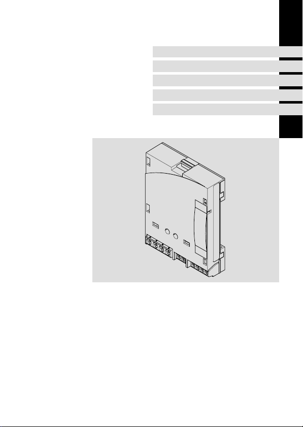
E82ZAFFC001
Funktionsmodul
Function module
Module de fonction
Page 2

Lesen Sie zuerst diese Anleitung und die Dokumentation zum Grundgerät,
bevor Sie mit den Arbeiten beginnen!
Beachten Sie die enthaltenen Sicherheitshinweise.
Please read these instructions and the documentation of the standard
device before you start working!
Observe the safety instructions given therein!
Lire le présent fascicule et la documentation relative à l’appareil de base
avant toute manipulation de l’équipement !
Respecter les consignes de sécurité fournies.
Page 3
E82ZAFF011B/011C
Page 4

0Abb. 0Tab. 0
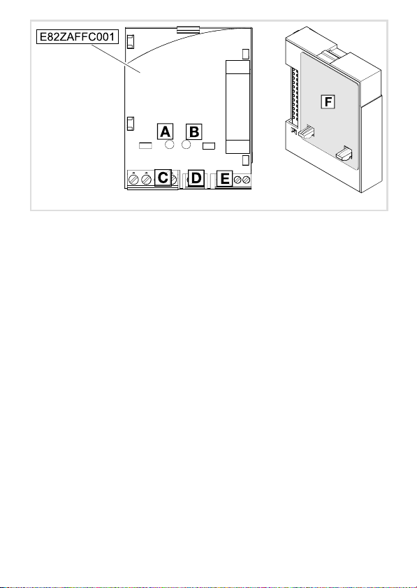
Legende zur Abbildung auf der Ausklappseite siehe
Funktionsmodul E82ZAFFC001
Status der Bus−Kommunikation (grüne LED)
Störung der Bus−Kommunikation (rote LED)
Anschluss für AS−interface
Anschluss für digitale Eingänge DI2 / DI3
Anschluss für
l interne Versorgung der Reglersperre
l Reglersperre (CINH)
Typenschild 5
16
16
14
Tipp!
Aktuelle Dokumentationen und Software−Updates zu Lenze Produkten finden
Sie im Internet jeweils im Bereich "Services & Downloads" unter
http://www.Lenze.com
4
EDK82ZAFFC−001 DE/EN/FR 6.0
Page 5
Gültigkeit
APPLICATION
010 / 3A22
Diese Anleitung ist gültig für
ƒ Funktionsmodule E82ZAFFC001 (AS−i / S) ab Version 4E
Diese Anleitung ist nur gültig zusammen mit der zugehörigen Betriebsanleitung der für den
Einsatz zulässigen Grundgeräte.
Identifikation
APPLICATION
010/ 3A22
Typenschlüssel E82ZAF F C 001 4x
Gerätereihe
AS−i / S
Gerätegeneration
Variante 001: Verlackte Ausführung
Hardwarestand
L
Type
Id.-No.
Prod.-No.
Ser.-No.
E82AF000P0B201XX
E82ZAFX005
Funktion
Das Funktionsmodul ermöglicht die Ansteuerung von Lenze−Frequenzumrichtern mit
seriell übertragenen Steuersignalen.
Einsetzbarkeit
Das Funktionsmodul ist einsetzbar mit folgenden Grundgeräten
Grundgerät ab Version
Frequenzumrichter
EDK82ZAFFC−001 DE/EN/FR 6.0
8200 vector Vx14
8200 motec Vx14
5
Page 6

i Inhalt
1 Sicherheitshinweise 7 . . . . . . . . . . . . . . . . . . . . . . . . . . . . . . . . . . . . . . . . . . . . . . . .
Definition der verwendeten Hinweise 7 . . . . . . . . . . . . . . . . . . . . . . . . . . . . . . . . .
2 Lieferumfang 9 . . . . . . . . . . . . . . . . . . . . . . . . . . . . . . . . . . . . . . . . . . . . . . . . . . . . . .
3 Mechanische Installation 10 . . . . . . . . . . . . . . . . . . . . . . . . . . . . . . . . . . . . . . . . . . . .
4 Elektrische Installation 11 . . . . . . . . . . . . . . . . . . . . . . . . . . . . . . . . . . . . . . . . . . . . . .
5 Inbetriebnahme 15 . . . . . . . . . . . . . . . . . . . . . . . . . . . . . . . . . . . . . . . . . . . . . . . . . . .
Vor dem ersten Einschalten 15 . . . . . . . . . . . . . . . . . . . . . . . . . . . . . . . . . . . . . . . . . .
Statusanzeige 16 . . . . . . . . . . . . . . . . . . . . . . . . . . . . . . . . . . . . . . . . . . . . . . . . . . . . .
Datentransfer 17 . . . . . . . . . . . . . . . . . . . . . . . . . . . . . . . . . . . . . . . . . . . . . . . . . . . . .
6 Technische Daten 19 . . . . . . . . . . . . . . . . . . . . . . . . . . . . . . . . . . . . . . . . . . . . . . . . . .
Allgemeine Daten und Einsatzbedingungen 19 . . . . . . . . . . . . . . . . . . . . . . . . . . . .
Schutzisolierung 20 . . . . . . . . . . . . . . . . . . . . . . . . . . . . . . . . . . . . . . . . . . . . . . . . . . .
Abmessungen 21 . . . . . . . . . . . . . . . . . . . . . . . . . . . . . . . . . . . . . . . . . . . . . . . . . . . . .
6
EDK82ZAFFC−001 DE/EN/FR 6.0
Page 7

Definition der verwendeten Hinweise
1 Sicherheitshinweise
Definition der verwendeten Hinweise
Um auf Gefahren und wichtige Informationen hinzuweisen, werden in dieser Dokumentation folgende Piktogramme und Signalwörter verwendet:
Sicherheitshinweise
Aufbau der Sicherheitshinweise:
Gefahr!
(kennzeichnet die Art und die Schwere der Gefahr)
Hinweistext
(beschreibt die Gefahr und gibt Hinweise, wie sie vermieden werden kann)
Piktogramm und Signalwort Bedeutung
Gefahr von Personenschäden durch gefährliche elektrische Spannung
Sicherheitshinweise
Gefahr!
Gefahr!
Stop!
Hinweis auf eine unmittelbar drohende Gefahr, die den
Tod oder schwere Verletzungen zur Folge haben kann,
wenn nicht die entsprechenden Maßnahmen getroffen
werden.
Gefahr von Personenschäden durch eine allgemeine Gefahrenquelle
Hinweis auf eine unmittelbar drohende Gefahr, die den
Tod oder schwere Verletzungen zur Folge haben kann,
wenn nicht die entsprechenden Maßnahmen getroffen
werden.
Gefahr von Sachschäden
Hinweis auf eine mögliche Gefahr, die Sachschäden zur
Folge haben kann, wenn nicht die entsprechenden Maßnahmen getroffen werden.
1
EDK82ZAFFC−001 DE/EN/FR 6.0
7
Page 8

1 Sicherheitshinweise
Definition der verwendeten Hinweise
Anwendungshinweise
Piktogramm und Signalwort Bedeutung
Hinweis!
Tipp!
Wichtiger Hinweis für die störungsfreie Funktion
Nützlicher Tipp für die einfache Handhabung
Verweis auf andere Dokumentation
8
EDK82ZAFFC−001 DE/EN/FR 6.0
Page 9
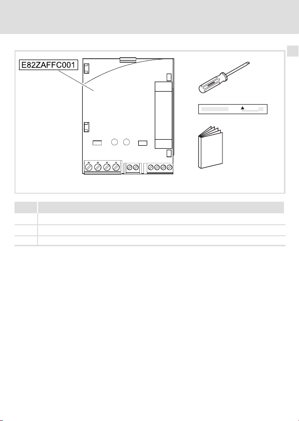
2 Lieferumfang
Pos. Lieferumfang
Schraubendreher
Klebestreifen
Montageanleitung
Lieferumfang 2
E82ZAFF011B
EDK82ZAFFC−001 DE/EN/FR 6.0
9
Page 10

3 Mechanische Installation
3 Mechanische Installation
Folgen Sie zur mechanischen Installation des Funktionsmoduls den Hinweisen in der Montageanleitung des Grundgerätes.
Die Montageanleitung des Grundgerätes ...
ƒ ist Teil des Lieferumfangs und liegt jedem Gerät bei.
ƒ gibt Hinweise, um Beschädigungen durch unsachgemäße Behandlung zu vermeiden.
ƒ beschreibt die einzuhaltende Reihenfolge der Installationsschritte.
10
EDK82ZAFFC−001 DE/EN/FR 6.0
Page 11

Elektrische Installation 4
4 Elektrische Installation
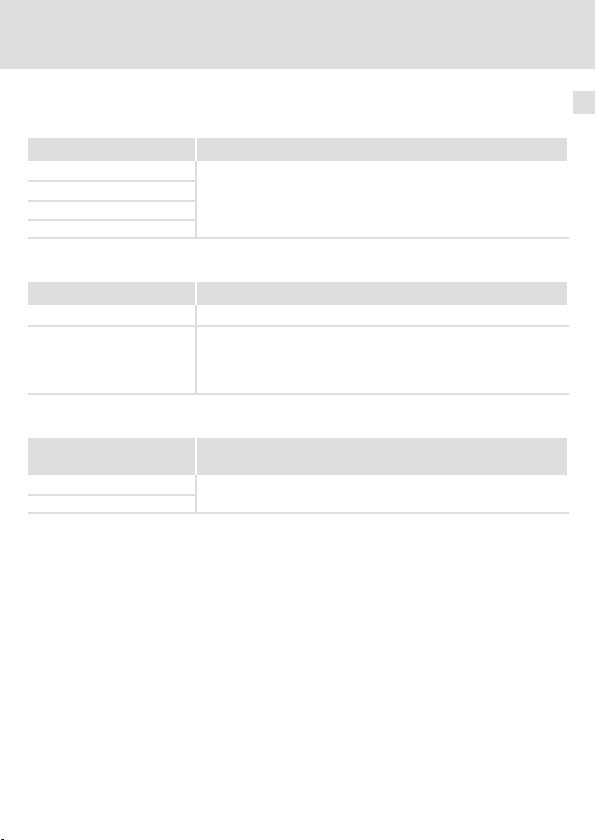
Daten der Anschlussklemmen
Elektrischer Anschluss Klemmenleiste mit Schraubanschluss
Anschlussmöglichkeiten
Anzugsmoment 0,5 ... 0,6 Nm (4.4 ... 5.3 lb−in)
Abisolierlänge 6 mm
starr: 1,5 mm
flexibel:
ohne Aderendhülse
1,5 mm
mit Aderendhülse, ohne Kunststoffhülse
1,5 mm
mit Aderendhülse, mit Kunststoffhülse
1,5 mm
Daten der Anschlussklemmen /
Klemmenleiste mit Schraubanschluss
Anschlussmöglichkeiten
Anzugsmoment
Abisolierlänge 5 mm
0,22 ... 0,25 Nm (1.9 ... 2.2 lb−in)
starr: 1,5 mm
flexibel:
ohne Aderendhülse
1,0 mm
mit Aderendhülse, ohne Kunststoffhülse
0,5 mm
mit Aderendhülse, mit Kunststoffhülse
0,5 mm
2
(AWG 16)
2
(AWG 16)
2
(AWG 16)
2
(AWG 18)
2
(AWG 20)
2
(AWG 20)
2
(AWG 16)
2
(AWG 16)
EDK82ZAFFC−001 DE/EN/FR 6.0
11
Page 12
4 Elektrische Installation
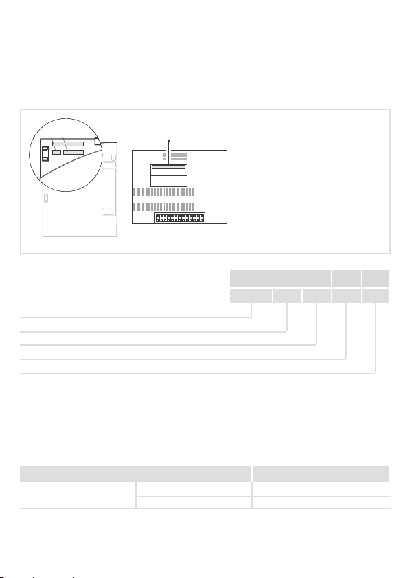
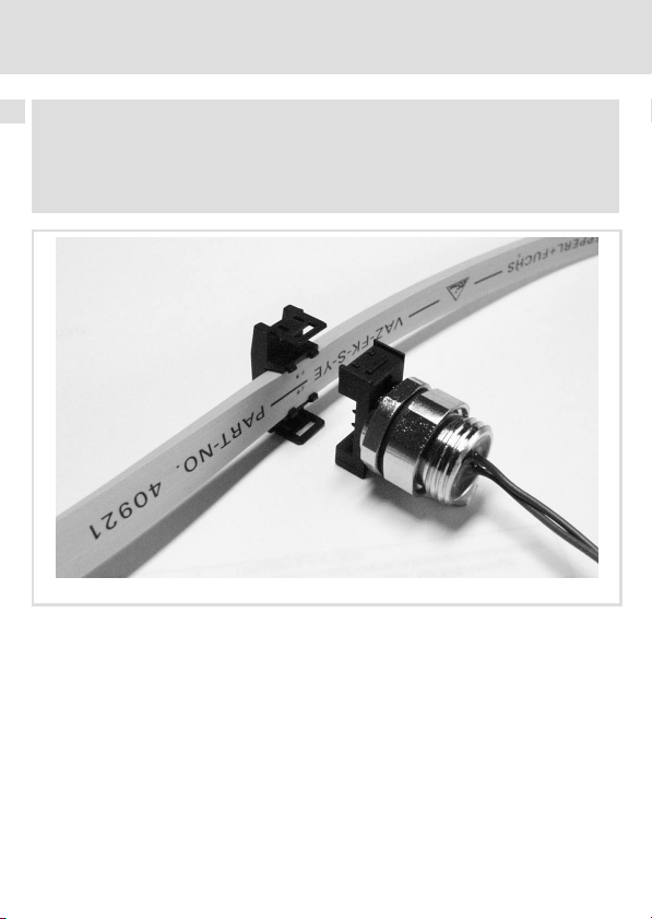
Hinweis!
Wenn Sie für den Busanschluss an 8200 motec ein Flachkabel verwenden,
empfehlen wir folgenden Adapter (Abb. unten):
Bestell−Bezeichnung E82ZMFF
1
1. Teil in ein passendes Gewinde des motec−Trägergehäuses einschrauben.
2. AS−i Flachkabel in Teil einlegen und seitenrichtig Teil auf Teil stecken.
3. Adapterschrauben festziehen.
4. Klemmenbelegung durchführen.
12
0
EDK82ZAFFC−001 DE/EN/FR 6.0
E82ZAFF004
Page 13
Elektrische Installation 4
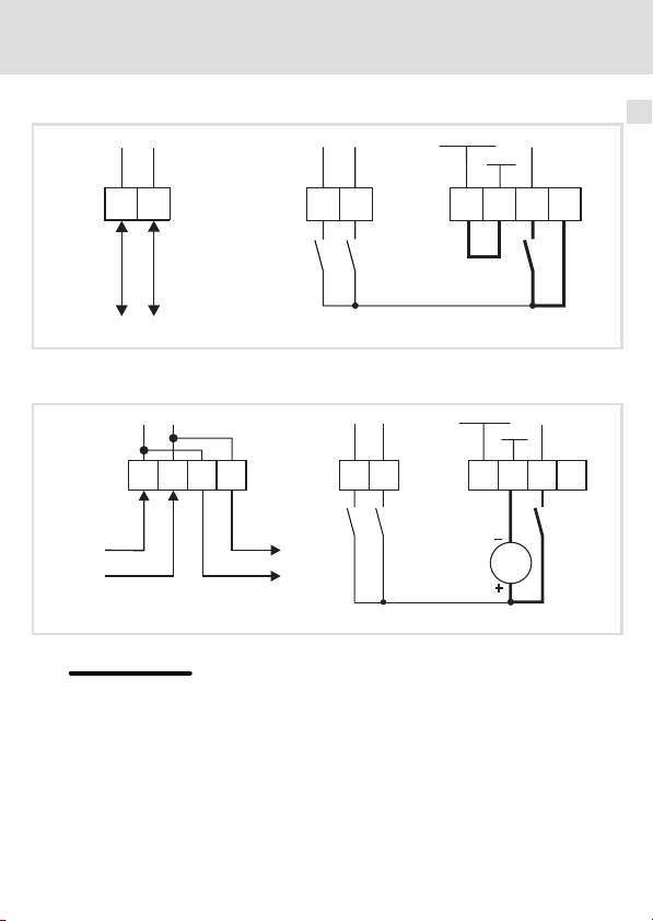
G
Versorgung der Reglersperre (CINH) über die interne Spannungsquelle (X3.3/20)
GND-ASi
GND
+U
_
X3.1
+
DI2
DI3
X3.3X3.2
7
AS-i (+) AS-i (-)
ASi
202839
E82ZAFF035
Versorgung der Reglersperre (CINH) über die externe Spannungsquelle
ND-ASi
X3.1
_
+
_
+
DI3DI2
7
X3.3X3.2
AS-i AS-i
Für den Betrieb notwendige Mindestverdrahtung
EDK82ZAFFC−001 DE/EN/FR 6.0
GND
39
+U
ASi
2028
E82ZAFF031
13
Page 14

4 Elektrische Installation
X3.1/ Litzenfarbe (IEC 757) Funktion
+ BN (braun)
− BU (blau)
X3.2/ Bezeichnung Funktion Pegel
DI2 Digitaler Eingang 1
DI3 Digitaler Eingang 2
X3.3/ Bezeichnung Funktion Pegel
7 GND−ASi Bezugspotential für X3.3/20
39 GND Bezugspotential der
28 CINH Reglersperre
20 +U
ASi
Beachten Sie die in der AS−i−Systembeschreibung enthaltenen
Hinweise zum elektrischen Anschluss von Peripheriegeräten.
Anwenderdefiniert 0 = LOW (0 ... +3 V)
l Reglersperre (CINH) an X3.3/28
l digitalen Eingänge DI2 und DI3
DC−Spannungsquelle zur internen Versorgung
l der Reglersperre (CINH)
l der digitalen Eingänge DI2
und DI3
1 = HIGH (+12 ... +30 V)
Bezug: GND
l Start = HIGH (+12 ... +30 V)
l Stopp = LOW (0 ... +3 V)
Versorgung über den AS−i−Bus
Bezug: GND−ASi
14
EDK82ZAFFC−001 DE/EN/FR 6.0
Page 15

Inbetriebnahme
Vor dem ersten Einschalten
5 Inbetriebnahme
Vor dem ersten Einschalten
Stop!
Bevor Sie das Grundgerät mit Funktionsmodul erstmalig im AS−i−Netzwerk
einschalten, überprüfen Sie die gesamte Verdrahtung auf Vollständigkeit,
Kurzschluss und Erdschluss.
5
EDK82ZAFFC−001 DE/EN/FR 6.0
15
Page 16

5 Inbetriebnahme
Statusanzeige
Statusanzeige
LED−Zustand
Grüne LED Rote LED
AUS AUS Keine Versorgungsspannung
EIN AUS Bus−Versorgung und Kommunikation sind in Ordnung.
EIN EIN
blinkt EIN Die Kommunikation ist nicht möglich, weil noch keine gültige Busteil-
Beschreibung
l Kommunikation ist unterbrochen.
l Schreiben eines Parameters ist nicht möglich.
l Ein "Watchdog IC Reset" ist erfolgt.
nehmeradresse zugewiesen wurde (Adresse = 0).
Hinweis!
ƒ Beachten Sie die Positionsmarkierungen auf der Ausklappseite.
ƒ Das Funktionsmodul wird über den AS−i−Bus mit Spannung versorgt.
16
EDK82ZAFFC−001 DE/EN/FR 6.0
Page 17
Inbetriebnahme
Datentransfer
Datentransfer
Transfer der AS−i−Datenbits (D0 ... D3) zum Antrieb
Belegung D0 ... D3 Konfiguration der digitalen Eingänge E1 ... E4 des Antriebsreglers
D0 = E1
D1 = E2
D2 = E3
D3 = E4
Transfer der AS−i−Datenbits (D0/D1) vom Antrieb
Belegung D0/D1 Konfiguration des digitalen Ausgangs A1 des Antriebsreglers
D0 = A1 à Anleitung des Antriebsreglers: Codestelle C0117
D1 = 0:
Antrieb vom Netz getrennt
D1 = 1:
Antrieb vom Netz versorgt
Transfer der AS−i−Datenbits (D2/D3) von den digitalen Eingängen
Belegung D2/D3 Konfiguration der digitalen Eingänge DI2 und DI3 des Funktionsmo-
D2 = DI2
D3 = DI3
à Anleitung des Antriebsreglers: Codestelle C0007
duls AS−i / S
Anwenderdefiniert
5
EDK82ZAFFC−001 DE/EN/FR 6.0
17
Page 18

5 Inbetriebnahme
Datentransfer
Beispiel zur Konfiguration des Antriebsreglers
ƒ Aufgabe:
Über den AS−i soll Schnellhalt (QSP) durch das Datenbit D1 im Antriebsregler gesetzt
werden.
ƒ Lösung:
Über die freie Konfiguration digitaler Eingangssignale (Codestelle C0410) muss der
Subcode 4 (DCTRL1−QSP) auf den Wert 2 (= digitaler Eingang E2) gesetzt werden.
Hinweis!
Zur Auswertung der digitalen Ausgangssignale muss die Codestelle C0415
konfiguriert werden.
18
EDK82ZAFFC−001 DE/EN/FR 6.0
Page 19

Allgemeine Daten und Einsatzbedingungen
6 Technische Daten
Allgemeine Daten und Einsatzbedingungen
Bereich Werte
Bestellbezeichnung E82ZAFFC001 (verlackte Ausführung)
Protokoll / Kommunikations-
medium
Netzwerk−Topologie Baum
Maximale Anzahl Teilnehmer 31
AS−i−Teilnehmer Single Slave
Slave−Profil S−7.F (I/O−Code: 7
Übertragungsrate [kBit/s] 167
Erreichbare Busleitungslänge Max. 100 m
Spannungsversorgung des
Funktionsmoduls
Zykluszeit 5 ms (bei 31 Knoten)
Umgebungsbedingungen
Klimatische Bedingungen
Lagerung
Transport 2 K3 nach IEC/EN 60721−3−2 − 25 ... + 70 °C
Verschmutzungsgrad 2 nach IEC/EN 61800−5−1
Schutzart IP20
X3.2/ Pegel
DI2
DI3
AS−i nach AS−i−Spezifikation 3.0
, ID−Code: F
hex
U
min
I
max
1 K3 nach IEC/EN 60721−3−1 − 25 ... + 60 °C
Betrieb 3 K3 nach IEC/EN 60721−3−3 − 20 ... + 60 °C
Eingangswiderstand: 3,3 k
0 = LOW (0 V DC − 0% ... +3 V DC + 0%)
1 = HIGH (+12 V DC − 0% ... +30 V DC + 0%)
Bezug: GND
18,5 V DC
³
140 mA
=
hex
W
Technische Daten
, ID2−Code: F
hex
)
6
X3.3/ Pegel
28
20 Max. Belastung: 70 mA
EDK82ZAFFC−001 DE/EN/FR 6.0
Eingangswiderstand: 3,3 k
Reglersperre
l Start = HIGH (+12 V DC − 0% ... +30 V DC + 0%)
l Stopp = LOW (0 V DC − 0% ... +3 V DC + 0%)
Bezug: GND−ASi
W
19
Page 20

6 Technische Daten
Schutzisolierung
Schutzisolierung
Isolationsspannung zwischen Bus und ... Art der Isolierung (nach EN 61800−5−1)
l Leistungsteil 8200 vector/motec
l Bezugserde/PE
l Klemme X3.2/DI2 bzw. X3.2/DI3
l Klemme X3.3/20
l Klemme X3.3/28
Doppelte Isolierung
Betriebsisolierung
Betriebsisolierung
Keine Isolierung
Betriebsisolierung
20
EDK82ZAFFC−001 DE/EN/FR 6.0
Page 21

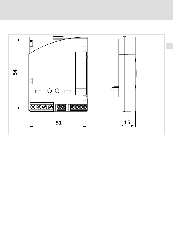
Abmessungen
alle Maße in mm
Technische Daten
Abmessungen
E82ZAFF011D
6
EDK82ZAFFC−001 DE/EN/FR 6.0
21
Page 22

0Fig. 0Tab. 0
Legend for fold−out page See
E82ZAFFC001 function module
Bus communication status (green LED)
Bus communication error (red LED)
Connection for AS interface
Connection for digital inputs DI2 / DI3
Connection for
l internal controller inhibit supply
l controller inhibit (CINH)
Nameplate 23
Tip!
Current documentation and software updates concerning Lenze products can
be found on the Internet in the "Services & Downloads" area under
http://www.Lenze.com
34
34
32
22
EDK82ZAFFC−001 DE/EN/FR 6.0
Page 23

Validity
APPLICATION
010 / 3A22
These instructions are valid for
ƒ E82ZAFFC001 (AS−i / S) function modules as of version 4E
These instructions are only valid together with the Operating Instructions for the standard
devices permitted for the application.
Identification
APPLICATION
010/ 3A22
Type code E82ZAF F C 001 4x
Series
AS−i / S
Generation
Variant 001: coated design
Hardware version
L
Type
Id.-No.
Prod.-No.
Ser.-No.
E82AF000P0B201XX
E82ZAFX005
Function
The function module enables frequency inverters from Lenze to be controlled by serial
control signals.
Application range
The function module can be used together with the following basic devices
Basic device as of version
Frequency inverter
EDK82ZAFFC−001 DE/EN/FR 6.0
8200 vector Vx14
8200 motec Vx14
23
Page 24

i Contents
1 Safety instructions 25 . . . . . . . . . . . . . . . . . . . . . . . . . . . . . . . . . . . . . . . . . . . . . . . . .
Definition of notes used 25 . . . . . . . . . . . . . . . . . . . . . . . . . . . . . . . . . . . . . . . . . . . . .
2 Scope of supply 27 . . . . . . . . . . . . . . . . . . . . . . . . . . . . . . . . . . . . . . . . . . . . . . . . . . . .
3 Mechanical installation 28 . . . . . . . . . . . . . . . . . . . . . . . . . . . . . . . . . . . . . . . . . . . . .
4 Electrical installation 29 . . . . . . . . . . . . . . . . . . . . . . . . . . . . . . . . . . . . . . . . . . . . . . .
5 Commissioning 33 . . . . . . . . . . . . . . . . . . . . . . . . . . . . . . . . . . . . . . . . . . . . . . . . . . . .
Before switching on 33 . . . . . . . . . . . . . . . . . . . . . . . . . . . . . . . . . . . . . . . . . . . . . . . .
Status display 34 . . . . . . . . . . . . . . . . . . . . . . . . . . . . . . . . . . . . . . . . . . . . . . . . . . . . .
Data transfer 35 . . . . . . . . . . . . . . . . . . . . . . . . . . . . . . . . . . . . . . . . . . . . . . . . . . . . . .
6 Technical data 37 . . . . . . . . . . . . . . . . . . . . . . . . . . . . . . . . . . . . . . . . . . . . . . . . . . . . .
General data and operating conditions 37 . . . . . . . . . . . . . . . . . . . . . . . . . . . . . . . . .
Protective insulation 38 . . . . . . . . . . . . . . . . . . . . . . . . . . . . . . . . . . . . . . . . . . . . . . .
Dimensions 39 . . . . . . . . . . . . . . . . . . . . . . . . . . . . . . . . . . . . . . . . . . . . . . . . . . . . . . .
24
EDK82ZAFFC−001 DE/EN/FR 6.0
Page 25

Safety instructions
Definition of notes used
1 Safety instructions
Definition of notes used
The following pictographs and signal words are used in this documentation to indicate
dangers and important information:
Safety instructions
Structure of safety instructions:
Danger!
(characterises the type and severity of danger)
Note
(describes the danger and gives information about how to prevent dangerous
situations)
Pictograph and signal word Meaning
Danger of personal injury through dangerous electrical
voltage.
Danger!
Danger!
Stop!
Reference to an imminent danger that may result in
death or serious personal injury if the corresponding
measures are not taken.
Danger of personal injury through a general source of
danger.
Reference to an imminent danger that may result in
death or serious personal injury if the corresponding
measures are not taken.
Danger of property damage.
Reference to a possible danger that may result in
property damage if the corresponding measures are not
taken.
1
EDK82ZAFFC−001 DE/EN/FR 6.0
25
Page 26

1 Safety instructions
Definition of notes used
Application notes
Pictograph and signal word Meaning
Note!
Tip!
Important note to ensure troublefree operation
Useful tip for simple handling
Reference to another documentation
26
EDK82ZAFFC−001 DE/EN/FR 6.0
Page 27

2 Scope of supply
Pos. Scope of supply
Screwdriver
Adhesive tape
Mounting Instructions
Scope of supply 2
E82ZAFF011B
EDK82ZAFFC−001 DE/EN/FR 6.0
27
Page 28

3 Mechanical installation
3 Mechanical installation
Follow the notes given in the Mounting Instructions for the standard device for the
mechanical installation of the function module.
The Mounting Instructions for the standard device ...
ƒ are part of the scope of supply and are enclosed with each device.
ƒ provide tips for avoiding damage through improper handling.
ƒ describe the obligatory order of installation steps.
28
EDK82ZAFFC−001 DE/EN/FR 6.0
Page 29

4 Electrical installation
Terminal data
Electrical connection Terminal strip with screw connection
Possible connections
Tightening torque 0.5 ... 0.6 Nm (4.4 ... 5.3 lb−in)
Bare end 6 mm
rigid: 1.5 mm
flexible:
without wire end ferrule
1.5 mm
with wire end ferrule, without plastic sleeve
1.5 mm
with wire end ferrule, with plastic sleeve
1.5 mm
2
(AWG 16)
2
(AWG 16)
2
(AWG 16)
2
(AWG 16)
Terminal data /
Terminal strip with screw connection
Possible connections
Tightening torque
Bare end 5 mm
0.22 ... 0.25 Nm (1.9 ... 2.2 lb−in)
rigid: 1.5 mm
flexible:
without wire end ferrule
1.0 mm
with wire end ferrule, without plastic sleeve
0.5 mm
with wire end ferrule, with plastic sleeve
0.5 mm
2
(AWG 18)
2
(AWG 20)
2
(AWG 20)
2
(AWG 16)
Electrical installation 4
EDK82ZAFFC−001 DE/EN/FR 6.0
29
Page 30

4 Electrical installation
Note!
If you use a flat cable for the bus connection to 8200 motec, we recommend
the following adapter (see picture below):
Order designation E82ZMFF
1
1. Screw component into the fitting thread of the motec carrier housing.
2. Insert AS−i flat cable into component and plug component onto component
3. Tighten the adapter screws
4. Assign the terminals.
30
0
E82ZAFF004
EDK82ZAFFC−001 DE/EN/FR 6.0
Page 31

Electrical installation 4
G
Controller inhibit (CINH) supply via the internal voltage source (X3.3/20)
GND-ASi
GND
_
X3.1
+
DI2
DI3
X3.3X3.2
7
AS-i (+) AS-i (-)
+U
202839
E82ZAFF035
ASi
Controller inhibit (CINH) supply via the external voltage source
X3.1
_
+
_
+
DI3DI2
X3.3X3.2
AS-i AS-i
Minimum wiring required for operation
EDK82ZAFFC−001 DE/EN/FR 6.0
ND-ASi
7
GND
39
+U
ASi
2028
E82ZAFF031
31
Page 32

4 Electrical installation
X3.1/ Litz wire colour
(IEC 757)
+ BN (brown)
− BU (blue)
X3.2/ Designation Function Level
DI2 Digital input 1
DI3 Digital input 2
X3.3/ Designation Function Level
7 GND ASi Reference potential for X3.3/20
39 GND Reference potential for
28 CINH Controller inhibit
20 +U
ASi
Function
Please observe the notes for the electrical connection of
peripherals in the AS−i system description.
User−defined 0 = LOW (0 ... +3 V)
l controller inhibit (CINH) at X3.3/28
l digital inputs DI2 and DI3
DC voltage source for internal
supply of
l controller inhibit (CINH)
l digital inputs DI2 and DI3
1 = HIGH (+12 ... +30 V)
Reference: GND
l Start = HIGH (+12 ... +30 V)
l Stop = LOW (0 ... +3 V)
Supply via the AS−i bus
Reference: GND ASi
32
EDK82ZAFFC−001 DE/EN/FR 6.0
Page 33

Commissioning
Before switching on
5 Commissioning
Before switching on
Stop!
Please check the entire wiring with regard to completeness, short circuit and
earth fault, before you switch on the basic device with function module for the
first time in the AS−i network.
5
EDK82ZAFFC−001 DE/EN/FR 6.0
33
Page 34

5 Commissioning
Status display
Status display
LED status
Green LED Red LED
OFF OFF No supply voltage
ON OFF Bus supply and communication are ok.
ON ON
BLINKING ON Communication not possible because no valid bus node address has
Description
l Communication is interrupted.
l Parameter writing not possible.
l "IC watchdog" has been reset.
been assigned (address = 0).
Note!
ƒ Please note the position markings on the fold−out page.
ƒ The function module is supplied via the AS−i bus.
34
EDK82ZAFFC−001 DE/EN/FR 6.0
Page 35

Commissioning
Data transfer
Data transfer
Transfer of AS−i data bits (D0 ... D3) to drive
Assignment D0 ... D3 Configuration of the digital controller inputs E1 ... E4
D0 = E1
D1 = E2
D2 = E3
D3 = E4
Transfer of AS−i data bits (D0/D1) from drive
Assignment D0/D1 Configuration of the digital controller output A1
D0 = A1 à See documentation for controller: Code C0117
D1 = 0:
Drive is disconnected from
the mains
D1 = 1:
Drive is supplied by the mains
Transfer of AS−i data bits (D2/D3) from digital inputs
Assignment D2/D3 Configuration of the digital inputs DI2 and DI3 of the AS−i / S
D2 = DI2
D3 = DI3
à See documentation for controller: Code C0007
function module
User−defined
5
EDK82ZAFFC−001 DE/EN/FR 6.0
35
Page 36

5 Commissioning
Data transfer
Example for controller configuration
ƒ Task definition:
Use the AS−i and set quick stop (QSP) in the controller through data bit D1.
ƒ Solution:
Use the free configuration of digital input signals (code C0410) and set the value of
subcode 4 (DCTRL1−QSP) to 2 (= digital input E2).
Note!
For the evaluation of digital output signals, code C0415 must be configured.
36
EDK82ZAFFC−001 DE/EN/FR 6.0
Page 37

General data and operating conditions
6 Technical data
General data and operating conditions
Field Values
Order designation E82ZAFFC001 (coated design)
Protocol / communication
medium
Network topology Tree
Maximum number of nodes 31
AS−i node Single slave
Slave profile S−7.F (I/O code: 7
Baud rate [kbit/s] 167
Maximum possible bus cable
length
Voltage supply for function
module
Cycle time 5 ms (for 31 nodes)
Ambient conditions
Climatic conditions
Transport 2 K3 acc. to IEC/EN 60721−3−2 − 25 ... + 70 °C
AS−i to AS−i specifications 3.0
, ID code: F
hex
Max. 100 m
U
min
I
max
Storage
1 K3 acc. to IEC/EN 60721−3−1 − 25 ... + 60 °C
18.5 V DC
³
140 mA
=
Technical data
, ID2 code: F
hex
hex
6
)
EDK82ZAFFC−001 DE/EN/FR 6.0
37
Page 38

6 Technical data
Protective insulation
Ambient conditions
Operation 3 K3 acc. to IEC/EN 60721−3−3
Degree of pollution 2 acc. to IEC/EN 61800−5−1
Enclosure IP20
X3.2/ Level
DI2
DI3
X3.3/ Level
28
20 Max. load: 70 mA
Input resistance: 3.3 k
0 = LOW (0 V DC − 0% ... +3 V DC + 0%)
1 = HIGH (+12 V DC − 0% ... +30 V DC + 0%)
Reference: GND
Input resistance: 3.3 k
Controller inhibit
l Start = HIGH (+12 V DC − 0% ... +30 V DC + 0%)
l Stop = LOW (0 V DC − 0% ... +3 V DC + 0%)
Reference: GND ASi
Protective insulation
Insulation voltage between bus and ... Type of insulation (to EN 61800−5−1)
l 8200 vector/motec power stage
l Reference earth/PE
l Terminal X3.2/DI2 or X3.2/DI3
l Terminal X3.3/20
l Terminal X3.3/28
Double insulation
Functional insulation
Functional insulation
No insulation
Functional insulation
− 20 ... + 60 °C
W
W
38
EDK82ZAFFC−001 DE/EN/FR 6.0
Page 39

Dimensions
All dimensions in mm
Technical data
Dimensions
E82ZAFF011D
6
EDK82ZAFFC−001 DE/EN/FR 6.0
39
Page 40

0Fig. 0Tab. 0
Légende de l’illustration de la page dépliante Voir
Module de fonction E82ZAFFC001
Etat de communication du bus (LED verte)
Défaut de communication du bus (LED rouge)
Raccord pour l’interface AS
Raccord pour les entrées numériques DI2 / DI3
Raccord pour
l l’alimentation interne du blocage variateur
l le blocage variateur (CINH)
Plaque signalétique 41
Conseil !
Les mises à jour de logiciels et les documentations récentes relatives aux
produits Lenze sont disponibles dans la zone "Téléchargements" du site
Internet :
http://www.Lenze.com
52
52
50
40
EDK82ZAFFC−001 DE/EN/FR 6.0
Page 41

Validité
APPLICATION
010 / 3A22
Le présent document s’applique aux produits suivants :
ƒ module de fonction E82ZAFFC001 (AS−i / S) à partir de la version 4E
Ce document est uniquement valable avec la documentation relative aux appareils de base
compatibles.
Identification
APPLICATION
010/ 3A22
Codification des types E82ZAF F C 001 4x
Série d’appareils
AS−i / S
Génération d’appareils
Variante 001 : version vernie
Version matérielle
L
Type
Id.-No.
Prod.-No.
Ser.-No.
E82AF000P0B201XX
E82ZAFX005
Fonction
Le module de fonction permet de relier les convertisseurs de fréquence Lenze et de les
commander via des signaux numériques.
Utilisation
Le module de fonction est compatible avec les appareils suivants :
Appareil de base A partir de la version :
Convertisseurs de fréquence
EDK82ZAFFC−001 DE/EN/FR 6.0
8200 vector Vx14
8200 motec Vx14
41
Page 42

i Sommaire
1 Consignes de sécurité 43 . . . . . . . . . . . . . . . . . . . . . . . . . . . . . . . . . . . . . . . . . . . . . . .
Définition des conventions utilisées 43 . . . . . . . . . . . . . . . . . . . . . . . . . . . . . . . . . . .
2 Equipement livré 45 . . . . . . . . . . . . . . . . . . . . . . . . . . . . . . . . . . . . . . . . . . . . . . . . . . .
3 Installation mécanique 46 . . . . . . . . . . . . . . . . . . . . . . . . . . . . . . . . . . . . . . . . . . . . . .
4 Installation électrique 47 . . . . . . . . . . . . . . . . . . . . . . . . . . . . . . . . . . . . . . . . . . . . . . .
5 Mise en service 51 . . . . . . . . . . . . . . . . . . . . . . . . . . . . . . . . . . . . . . . . . . . . . . . . . . . .
Avant la première mise sous tension 51 . . . . . . . . . . . . . . . . . . . . . . . . . . . . . . . . . . .
Affichage d’état 52 . . . . . . . . . . . . . . . . . . . . . . . . . . . . . . . . . . . . . . . . . . . . . . . . . . . .
Transfert de données 53 . . . . . . . . . . . . . . . . . . . . . . . . . . . . . . . . . . . . . . . . . . . . . . .
6 Spécifications techniques 55 . . . . . . . . . . . . . . . . . . . . . . . . . . . . . . . . . . . . . . . . . . .
Caractéristiques générales et conditions d’utilisation 55 . . . . . . . . . . . . . . . . . . . . .
Isolement de protection 56 . . . . . . . . . . . . . . . . . . . . . . . . . . . . . . . . . . . . . . . . . . . . .
Encombrements 57 . . . . . . . . . . . . . . . . . . . . . . . . . . . . . . . . . . . . . . . . . . . . . . . . . . .
42
EDK82ZAFFC−001 DE/EN/FR 6.0
Page 43

Définition des conventions utilisées
1 Consignes de sécurité
Définition des conventions utilisées
Pour indiquer des risques et des informations importantes, la présente documentation
utilise les mots et symboles suivants :
Consignes de sécurité
Présentation des consignes de sécurité
Danger !
(Le pictogramme indique le type de risque.)
Explication
(L’explication décrit le risque et les moyens de l’éviter.)
Pictogramme et mot associé Explication
Situation dangereuse pour les personnes en raison d’une
tension électrique élevée
Consignes de sécurité
Danger !
Danger !
Stop !
Indication d’un danger imminent qui peut avoir pour
conséquences des blessures mortelles ou très graves en
cas de non−respect des consignes de sécurité
correspondantes
Situation dangereuse pour les personnes en raison d’un
danger d’ordre général
Indication d’un danger imminent qui peut avoir pour
conséquences des blessures mortelles ou très graves en
cas de non−respect des consignes de sécurité
correspondantes
Risques de dégâts matériels
Indication d’un risque potentiel qui peut avoir pour
conséquences des dégâts matériels en cas de non−respect
des consignes de sécurité correspondantes
1
EDK82ZAFFC−001 DE/EN/FR 6.0
43
Page 44

1 Consignes de sécurité
Définition des conventions utilisées
Consignes d’utilisation
Pictogramme et mot associé Explication
Remarque
importante !
Conseil !
Remarque importante pour assurer un fonctionnement
correct
Conseil utile pour faciliter la mise en oeuvre
Référence à une autre documentation
44
EDK82ZAFFC−001 DE/EN/FR 6.0
Page 45

2 Equipement livré
Pos. Equipement livré
Tournevis
Bande autocollante
Instructions de montage
Equipement livré 2
E82ZAFF011B
EDK82ZAFFC−001 DE/EN/FR 6.0
45
Page 46

3 Installation mécanique
3 Installation mécanique
Pour l’installation mécanique du module de fonction, suivre les consignes fournies dans les
instructions de montage de l’appareil de base.
Les instructions de montage de l’appareil de base ...
ƒ font partie de la livraison standard et sont comprises dans l’emballage.
ƒ contiennent des consignes pour éviter des dommages dus à un emploi
contre−indiqué.
ƒ décrivent l’ordre à respecter pour les opérations d’installation.
46
EDK82ZAFFC−001 DE/EN/FR 6.0
Page 47

4 Installation électrique
Données relatives aux borniers de raccordement
Raccordement électrique Bornier avec fixation par vis
Raccordements possibles
Couple de serrage
Longueur du fil dénudé 6 mm
0,5 à 0,6 Nm (4,4 à 5,3 lb−in)
Fixe : 1,5 mm
Flexible :
sans embout
1,5 mm
avec embout, sans gaine plastifiée
1,5 mm
avec embout et gaine plastifiée
1,5 mm
2
(AWG 16)
2
(AWG 16)
2
(AWG 16)
2
Données relatives aux borniers de raccordement /
Bornier avec fixation par vis
Raccordements possibles
Couple de serrage
Longueur du fil dénudé 5 mm
0,22 ... 0,25 Nm (1.9 ... 2.2 lb−in)
Fixe : 1,5 mm
Flexible :
sans embout
1,0 mm
avec embout, sans gaine plastifiée
0,5 mm
avec embout et gaine plastifiée
0,5 mm
2
(AWG 18)
2
(AWG 20)
2
(AWG 20)
2
Installation électrique 4
(AWG 16)
(AWG 16)
EDK82ZAFFC−001 DE/EN/FR 6.0
47
Page 48

4 Installation électrique
Remarque importante !
En cas d’utilisation d’un câble en nappe pour le raccordement du bus au 8200
motec, nous recommandons l’adaptateur suivant (fig. ci−dessous) :
Référence de commande E82ZMFF
1
1. Visser l’élément dans l’embase du motec, en utilisant le filetage prévu à cet effet.
2. Poser le câble en nappe AS−i dans l’élément et enficher l’élément dans l’élément
du bon côté
3. Serrer les vis de l’adaptateur
4. Relier les bornes.
48
0
E82ZAFF004
EDK82ZAFFC−001 DE/EN/FR 6.0
Page 49

Installation électrique 4
G
Alimentation du blocage variateur (CINH) via la source de tension interne (X3.3/20)
GND-ASi
GND
+U
_
X3.1
+
DI2
DI3
X3.3X3.2
7
202839
AS-i (+) AS-i (-)
E82ZAFF035
ASi
Alimentation du blocage variateur (CINH) via la source de tension externe
ND-ASi
GND
X3.1
_
+
_
+
DI3DI2
7
X3.3X3.2
AS-i AS-i
Câblage minimal nécessaire au fonctionnement
EDK82ZAFFC−001 DE/EN/FR 6.0
39
+U
ASi
2028
E82ZAFF031
49
Page 50

4 Installation électrique
X3.1/ Couleur de tresse (CEI
757)
+ BN (brun)
− BU (bleu)
X3.2/ Désignation Fonction Niveau
DI2 Entrée numérique 1
DI3 Entrée numérique 2
X3.3/ Désignation Fonction Niveau
7 GND−ASi Potentiel de référence pour X3.3/20
39 GND Potentiel de référence
28 CINH Blocage variateur
20 +U
ASi
Fonction
Tenir compte des remarques fournies dans le descriptif du système
AS−i pour le raccordement électrique de périphériques.
Spécifique à l’application 0 = BAS (0 ... +3 V)
l du blocage variateur (CINH) sur X3.3/28
l des entrées numériques DI2 et DI3
Source de tension CC pour
l’alimentation interne
l du blocage variateur
(CINH),
l des entrées numériques
DI2 et DI3
1 = HAUT (+12 ... +30 V)
Référence : GND
l Marche = HAUT (+12 ... +30 V)
l Arrêt = BAS (0 ... +3 V)
Alimentation via le bus AS−i
Référence : GND−ASi
50
EDK82ZAFFC−001 DE/EN/FR 6.0
Page 51

Avant la première mise sous tension
5 Mise en service
Avant la première mise sous tension
Stop !
Avant la première connexion de l’appareil de base avec module de fonction sur
le réseau AS−i, vérifier si le câblage est complet et rechercher les éventuels
courts−circuits et défauts de mise à la terre.
Mise en service
5
EDK82ZAFFC−001 DE/EN/FR 6.0
51
Page 52

5 Mise en service
Affichage d’état
Affichage d’état
Etat des LED
LED verte LED rouge
Eteinte Eteinte Aucune tension d’alimentation
Allumée Eteinte L’alimentation du bus et la communication fonctionnent correctement.
Allumée Allumée
Clignotante Allumée La communication n’est pas possible car aucune adresse de participant
Description
l La communication est coupée.
l Il n’est pas possible d’écrire un paramètre.
l Un "Watchdog IC Reset" s’est produit.
au bus valable n’a été affectée (adresse = 0).
Remarque importante !
ƒ Tenir compte des repères de position sur la page dépliante.
ƒ Le module de fonction est alimenté en tension par le bus AS−i.
52
EDK82ZAFFC−001 DE/EN/FR 6.0
Page 53

Mise en service
Transfert de données
Transfert de données
Transfert des bits de données AS−i (D0 à D3) vers l’entraînement
Affectation D0 à D3 Configuration des entrées numériques E1 à E4 du variateur
D0 = E1
D1 = E2
D2 = E3
D3 = E4
Transfert des bits de données AS−i (D0/D1) en provenance de l’entraînement
Affectation D0/D1 Configuration de la sortie numérique A1 du variateur
D0 = A1 à Instructions de mise en service du variateur : code C0117
D1 = 0 :
Entraînement coupé du
réseau
D1 = 1 :
Entraînement alimenté par le
réseau
Transfert des bits de données (D2/D3) en provenance des entrées numériques
Affectation D2/D3 Configuration des entrées numériques DI2 et DI3 du module de
D2 = DI2
D3 = DI3
à Instructions de mise en service du variateur : code C0007
fonction AS−i / S
Configuration utilisateur
5
EDK82ZAFFC−001 DE/EN/FR 6.0
53
Page 54

5 Mise en service
Transfert de données
Exemple de configuration du variateur
ƒ Tâche :
Avec le module AS−i, régler l’arrêt rapide (QSP) dans le variateur au moyen du bit de
données D1.
ƒ Solution :
Par la libre configuration des signaux d’entrée numériques (code C0410), le sous−code
4 (DCTRL1−QSP) doit être défini sur la valeur 2 (= entrée numérique E2).
Remarque importante !
Pour le traitement des signaux de sortie numériques, le code C0415 doit être
configuré.
54
EDK82ZAFFC−001 DE/EN/FR 6.0
Page 55

Caractéristiques générales et conditions d’utilisation
Spécifications techniques
6 Spécifications techniques
Caractéristiques générales et conditions d’utilisation
Domaine Valeurs
Référence de commande E82ZAFFC001 (version vernie)
Protocole / Support de
communication
Topologie du réseau Arborescence
Nombre maximum de
participants
Participants AS−i Esclave seul
Profil de l’esclave S−7.F (code E/S : 7
Vitesse de transmission
[kbits/s]
Longueur de câble bus possible 100 m max.
Alimentation du module de
fonction
Temps de cycle 5 ms (pour 31 noeuds)
Conditions ambiantes
Conditions climatiques
Stockage
Transport 2 K3 selon CEI/EN 60721−3−2 − 25 ... + 70 °C
AS−i selon la spécification AS−i 3.0
31
, code ID : F
167
U
³
min
I
=
max
1 K3 selon CEI/EN 60721−3−1 − 25 ... + 60 °C
hex
18,5 V CC
140 mA
hex
, code ID2 : F
hex
6
)
EDK82ZAFFC−001 DE/EN/FR 6.0
55
Page 56

6 Spécifications techniques
Isolement de protection
Conditions ambiantes
Fonctionnement 3 K3 selon CEI/EN 60721−3−3
Degré de pollution 2 selon CEI/EN 61800−5−1
Indice de protection IP20
X3.2/ Niveau
DI2
DI3
X3.3/ Niveau
28
20 Charge max. : 70 mA
Résistance d’entrée : 3,3 k
0 = BAS (0 V CC − 0% ... +3 V CC + 0%)
1 = HAUT (+12 V CC − 0% ... +30 V CC + 0%)
Référence : GND
Résistance d’entrée : 3,3 k
Blocage variateur
l Démarrage = HAUT (+12 V CC − 0% ... +30 V CC + 0%)
l Arrêt = BAS (0 V CC − 0% ... +3 V CC + 0%)
Référence : GND−ASi
Isolement de protection
Tension d’isolement entre le bus et ... Type d’isolement (selon EN 61800−5−1)
l partie puissance 8200 vector/motec
l point de terre/PE
l borne X3.2/DI2 ou X3.2/DI3
l borne X3.3/20
l borne X3.3/28
Double isolement
Isolement fonctionnel
Isolement fonctionnel
Pas d’isolement
Isolement fonctionnel
− 20 ... + 60 °C
W
W
56
EDK82ZAFFC−001 DE/EN/FR 6.0
Page 57
Encombrements
Toutes les cotes en mm
Spécifications techniques
Encombrements
E82ZAFF011D
6
EDK82ZAFFC−001 DE/EN/FR 6.0
57
Page 58

© 06/2009
Lenze Drives GmbH
F
Postfach 10 13 52
D−31763 Hameln
Germany
(
+49(0)5154/ 82−0
Ê
+49(0)5154/ 82−28 00
Lenze@Lenze.de
ü
www.Lenze.com
Service Lenze Service GmbH
Breslauer Straße 3
D−32699 Extertal
Germany
(
008000/ 2446877 (24 h helpline)
Ê
+49(0)5154/ 82−11 12
Service@Lenze.de
EDK82ZAFFC−001 § .>xn § DE/EN/FR § 6.0 § TD17
10987654321
 Loading...