

Page 1
EDK82ZAFCC-200
.C$x
Ä.C$xä
Montageanleitung
Mounting Instructions
Instructions de montage
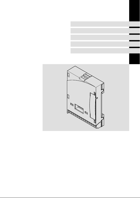
CAN-I/O
E82ZAFCC200
Funktionsmodul
Function module
Module de fonction
Page 2

Lesen Sie zuerst diese Anleitung und die Dokumentation zum Grundgerät,
bevor Sie mit den Arbeiten beginnen!
Beachten Sie die enthaltenen Sicherheitshinweise.
Please read these instructions and the documentation of the standard
device before you start working!
Observe the safety instructions given therein!
Lire le présent fascicule et la documentation relative à l’appareil de base
avant toute manipulation de l’équipement !
Respecter les consignes de sécurité fournies.
Page 3
E82ZAFC200B
Page 4

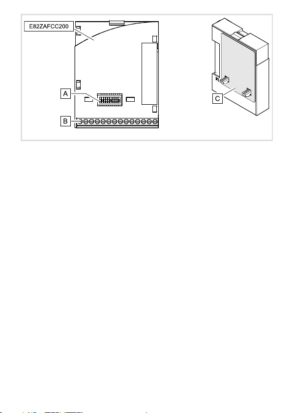
Legende zur Abbildung auf der Ausklappseite
Pos. Beschreibung Ausführliche
DIP-Schalter zur Einstellung der
Knotenadresse (Schalter 1 ... 6)
Übertragungsrate (Schalter 1 ... 7)
Klemmenleiste X3, Anschluss für
Systembus (CAN)
Reglersperre (CINH)
Typenschild 13
0Abb.0Tab. 0
Information
26
21
4
EDK82ZAFCC-200 DE/EN/FR 4.0
Page 5

Inhalt i
1 Über diese Dokumentation 6. . . . . . . . . . . . . . . . . . . . . . . . . . . . . . . . . . . . . . . . . .
Verwendete Konventionen 7. . . . . . . . . . . . . . . . . . . . . . . . . . . . . . . . . . . . . . . . . .
Verwendete Hinweise 8. . . . . . . . . . . . . . . . . . . . . . . . . . . . . . . . . . . . . . . . . . . . . . .
2 Sicherheitshinweise 10. . . . . . . . . . . . . . . . . . . . . . . . . . . . . . . . . . . . . . . . . . . . . . . .
3 Produktbeschreibung 11. . . . . . . . . . . . . . . . . . . . . . . . . . . . . . . . . . . . . . . . . . . . . . .
Bestimmungsgemäße Verwendung 11. . . . . . . . . . . . . . . . . . . . . . . . . . . . . . . . . . .
Lieferumfang 12. . . . . . . . . . . . . . . . . . . . . . . . . . . . . . . . . . . . . . . . . . . . . . . . . . . . . .
Identifikation 13. . . . . . . . . . . . . . . . . . . . . . . . . . . . . . . . . . . . . . . . . . . . . . . . . . . . . .
4 Technische Daten 14. . . . . . . . . . . . . . . . . . . . . . . . . . . . . . . . . . . . . . . . . . . . . . . . . .
Allgemeine Daten 14. . . . . . . . . . . . . . . . . . . . . . . . . . . . . . . . . . . . . . . . . . . . . . . . .
Einsatzbedingungen 14. . . . . . . . . . . . . . . . . . . . . . . . . . . . . . . . . . . . . . . . . . . . . . . .
Schutzisolierung 15. . . . . . . . . . . . . . . . . . . . . . . . . . . . . . . . . . . . . . . . . . . . . . . . . . .
Daten der Anschlussklemmen 15. . . . . . . . . . . . . . . . . . . . . . . . . . . . . . . . . . . . . . . .
Abmessungen 16. . . . . . . . . . . . . . . . . . . . . . . . . . . . . . . . . . . . . . . . . . . . . . . . . . . . .
5 Mechanische Installation 17. . . . . . . . . . . . . . . . . . . . . . . . . . . . . . . . . . . . . . . . . . . .
6 Elektrische Installation 18. . . . . . . . . . . . . . . . . . . . . . . . . . . . . . . . . . . . . . . . . . . . . .
EMV-gerechte Verdrahtung 18. . . . . . . . . . . . . . . . . . . . . . . . . . . . . . . . . . . . . . . . . .
Verdrahtung mit einem Leitrechner 19. . . . . . . . . . . . . . . . . . . . . . . . . . . . . . . . . . .
Daten der Anschlussklemmen 20. . . . . . . . . . . . . . . . . . . . . . . . . . . . . . . . . . . . . . . .
Belegung der Anschlussklemmen 21. . . . . . . . . . . . . . . . . . . . . . . . . . . . . . . . . . . . .
Busleitungslänge 23. . . . . . . . . . . . . . . . . . . . . . . . . . . . . . . . . . . . . . . . . . . . . . . . . .
7 Inbetriebnahme 26. . . . . . . . . . . . . . . . . . . . . . . . . . . . . . . . . . . . . . . . . . . . . . . . . . .
Einstellmöglichkeiten durch DIP-Schalter 26. . . . . . . . . . . . . . . . . . . . . . . . . . . . . .
Vor dem ersten Einschalten 29. . . . . . . . . . . . . . . . . . . . . . . . . . . . . . . . . . . . . . . . . .
Erstes Einschalten 30. . . . . . . . . . . . . . . . . . . . . . . . . . . . . . . . . . . . . . . . . . . . . . . . . .
Basisidentifier der CAN-Objekte 32. . . . . . . . . . . . . . . . . . . . . . . . . . . . . . . . . . . . . .
EDK82ZAFCC-200 DE/EN /FR 4.0
5
Page 6

1 Über diese Dokumentation
1 Überdiese Dokumentation
Inhalt
Diese Dokumentation enthält ...
ƒ Sicherheitshinweise, die Sie unbedingt beachten müssen;
ƒ Angaben über Versionsstände der zu verwendenden Lenze Grundgeräte;
ƒ Informationen zur mechanischen und elektrischen Installation des Funktionsmoduls;
ƒ Informationen zur Inbetriebnahme des Funktionsmoduls;
ƒ Technische Daten.
Tipp!
Weiterführende Informationen zu diesem Funktionsmodul finden Sie im
entsprechenden Kommunikationshandbuch.
Die PDF-Datei finden Sie im Internet im Bereich ”Services & Downloads” unter
http://www.Lenze.com
Zielgruppe
Diese Dokumentation wendetsichanPersonen,die das beschriebene Produkt nach Projektvorgabe installieren und in Betrieb nehmen.
Informationen zur Gültigkeit
Die Informationen in dieser Dokumentation sind gültig für folgende Geräte:
Funktionsmodul Typenbezeichnung ab Hardwarestand
CAN-I/O E82ZAFCC20x 3A
Tipp!
Dokumentationen und Software-Updates zu weiteren Lenze Produkten finden
Sie im Internet im Bereich ”Services & Downloads” unter
http://www.Lenze.com
6
EDK82ZAFCC-200 DE/EN/FR 4.0
Page 7

Über diese Dokumentation
Verwendete Konventionen
Verwendete Konventionen
Diese Dokumentation verwendet folgende Konventionen zur Unterscheidung verschiedener Arten von Information:
Informationsart Auszeichnung Beispiele/Hinweise
Zahlenschreibweise
Dezimaltrennzeichen Punkt Es wird generell der Dezimalpunkt
Symbole
Seitenverweis
verwendet.
Beispiel: 1234.56
Verweis auf eine andere Seite mit zusätzlichen Informationen
Beispiel:16 = siehe Seite 16
1
EDK82ZAFCC-200 DE/EN/FR 4.0
7
Page 8

1 Über diese Dokumentation
Verwendete Hinweise
Verwendete Hinweise
Um auf Gefahren und wichtige Informationen hinzuweisen, werden in dieser Dokumentation folgende Piktogramme und Signalwörter verwendet:
Sicherheitshinweise
Aufbau der Sicherheitshinweise:
Gefahr!
(kennzeichnet die Art und die Schwere der Gefahr)
Hinweistext
(beschreibt die Gefahr und gibt Hinweise, wie sie vermieden werden kann)
Piktogramm und Signalwort Bedeutung
Gefahr von Personenschäden durch gefährliche elektrische Spannung
Gefahr!
Gefahr!
Stop!
Hinweis auf eine unmittelbar drohende Gefahr, die den
Tod oder schwere Verletzungen zur Folge haben kann,
wenn nicht die entsprechenden Maßnahmen getroffen
werden.
Gefahr von Personenschäden durch eine allgemeine Gefahrenquelle
Hinweis auf eine unmittelbar drohende Gefahr, die den
Tod oder schwere Verletzungen zur Folge haben kann,
wenn nicht die entsprechenden Maßnahmen getroffen
werden.
Gefahr von Sachschäden
Hinweis auf eine mögliche Gefahr, die Sachschäden zur
Folge haben kann, wenn nicht die entsprechenden Maßnahmen getroffen werden.
8
EDK82ZAFCC-200 DE/EN/FR 4.0
Page 9

Anwendungshinweise
Piktogramm und Signalwort Bedeutung
Über diese Dokumentation
Verwendete Hinweise
1
Hinweis!
Tipp!
Wichtiger Hinweis für die störungsfreie Funktion
Nützlicher Tipp für die einfache Handhabung
Verweis auf andere Dokumentation
EDK82ZAFCC-200 DE/EN/FR 4.0
9
Page 10

2 Sicherheitshinweise
2 Sicherheitshinweise
Gefahr!
Unsachgemäßer Umgang mit dem Funktionsmodul und dem Grundgerät kann
schwere Personenschäden und Sachschäden verursachen.
Beachten Sie die in der Dokumentation zum Grundgerät enthaltenen
Sicherheitshinweise und Restgefahren.
Stop!
Elektrostatische Entladung
Durch elektrostatische Entladung können elektronische Bauteile innerhalb des
Funkionsmoduls beschädigt oder zerstört werden.
Mögliche Folgen:
ƒ
Das Funktionsmodul ist defekt.
ƒ
Die Feldbus-Kommunikation ist nicht möglich oder fehlerhaft.
Schutzmaßnahmen
ƒ
Befreien Sie sich vor dem Berühren des Moduls von elektrostatischen
Aufladungen.
10
EDK82ZAFCC-200 DE/EN/FR 4.0
Page 11

Bestimmungsgemäße Verwendung
Produktbeschreibung
3 Produktbeschreibung
Bestimmungsgemäße Verwendung
Das Funktionsmodul ...
ƒ koppelt Lenze Frequenzumrichter an das Kommunikationssystem CAN.
ƒ ist ein Betriebsmittel zum Einsatz in industriellen Starkstromanlagen.
ƒ ist eine Zubehör-Baugruppe, die mit folgenden Lenze Frequenzumrichtern eingesetzt
werden kann:
Gerätereihe ab Version
Frequenzumrichter
Antriebs-SPS Drive PLC 1x20
8200 vector Vx21
8200 motec Vx21
3
EDK82ZAFCC-200 DE/EN/FR 4.0
11
Page 12
3 Produktbeschreibung
1 2 3 4
5
7 7 7 E1
LO LO
28 E2 2028
HI HI
3939
Adress
Bd
12 3 45678 9 10
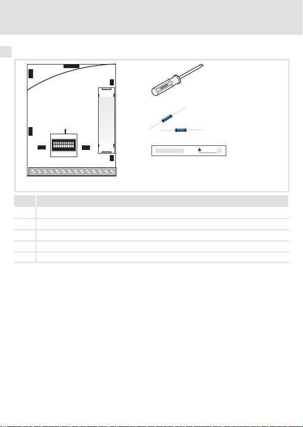
Lieferumfang
Lieferumfang
Pos. Lieferumfang
Funktionsmodul E82ZAFCC200
Montageanleitung
Schraubendreher
Zwei Busabschluss-Widerstände (je 120Ω)
Klebestreifen
E82ZAFC004
12
EDK82ZAFCC-200 DE/EN/FR 4.0
Page 13
Identifikation
E82AF000P0B201XX
APPLICATION
010/3A22
APPLICATION
010/3A22
L
Type
Id.-No.
Prod.-No.
Ser.-No.
Gerätereihe
CAN
Gerätegeneration
Variante
200: unverlackte Ausführung
201: verlackte Ausführung
Hardwarestand
Softwarestand
Produktbeschreibung
Identifikation
E82ZAFX005
E82ZAF C C 20x 3A
3
EDK82ZAFCC-200 DE/EN/FR 4.0
13
Page 14

4 Technische Daten
Allgemeine Daten
4 Technische Daten
Allgemeine Daten
Bereich Werte
Bestell-Bezeichnung E82ZAFCC2xx (xx: siehe 13)
Kommunikationsprofil angelehnt an CANopen
Kommunikationsmedium ISO11898
Netzwerk-Topologie
Knotenadressen Max. 63
Übertragungsrate [kBit/s] 20, 50, 125, 250, 500
Einsatzbedingungen
Umgebungsbedingungen
Klimatisch
Lagerung IEC/EN 60721-3-1 1K3 (-25 ... +60 °C)
Transport IEC/EN 60721-3-2 2K3 (-25 ... +70 °C)
Betrieb Entsprechend der Daten des verwendeten Lenze Grundgerätes (siehe
Verschmutzung EN 61800-5-1 Verschmutzungsgrad 2
Schutzart IP20 (Berührschutz nach NEMA 250 Typ 1)
Linie (beidseitig abgeschlossen mit 120ΩWiderstand)
Dokumentation des Grundgerätes).
14
EDK82ZAFCC-200 DE/EN/FR 4.0
Page 15

Technische Daten
Schutzisolierung
Schutzisolierung
Isolierung zwischen Busund ... Art der Isolierung (nach EN 61800-5-1)
Leistungsteil
– 8200 vector Verstärkte Isolierung
– 8200 motec Verstärkte Isolierung
= 20 V DC
= 30 mA
Betriebsisolierung
Betriebsisolierung
Betriebsisolierung
Ω
= 12 V DC - 0 % ... 30 V DC + 0 %
ext
Ω
Bezugserde / PE (X3/7)
Versorgung für CINH (X3/20)
Reglersperre, CINH (X3/28)
Daten der Anschlussklemmen
Klemme
X3/
39 GND2 Bezugspotenzial 2 der Reglersperre (CINH) an X3/28
28 CINH Reglersperre
7 GND1 Bezugspotenzial1
LO CAN-LOW CAN-Datenleitung (LOW)
HI CAN-HIGH CAN-Datenleitung (HIGH)
E1, E2 Digitale Ein-
20 Spannungsquelle zur internen Versorgung
Bezeichnung Funktion / Pegel
Eingangswiderstand: 3.3 k
Start = HIGH (12 ... 30 V DC)
Stopp = LOW (0 ... 3 V DC)
Bezug: GND2
Externe Versorgung mit U
Interne Versorgung über Klemme X3/20
gänge
Anwenderdefiniert
Eingangswiderstand: 3.3 k
0 = LOW (0 ... 3 V) SPS-Pegel, HTL
1 = HIGH (12 ... 30 V) SPS-Pegel, HTL
Bezug: GND2
E1 ist wahlweise auch als Frequenzeingang nutzbar (0 ... 10 kHz,
einspurig oder 0 ... 1 kHz zweispurig, Konfiguration über C0425).
U
int
I
max
Bezug: GND1
4
EDK82ZAFCC-200 DE/EN/FR 4.0
15
Page 16
4 Technische Daten
1 2 3 4
5
7 7 7 E1
LO LO
28 E2 2028
HI HI
3939
Adress
Bd
12 3 45678 9 10
0
0
0
b
a
c
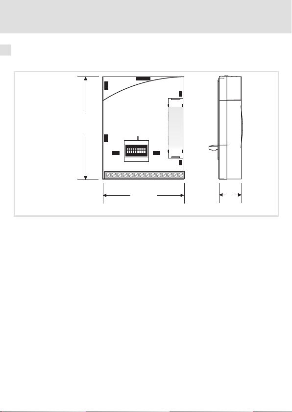
Abmessungen
Abmessungen
Funktionsmodul E82ZAFCC20x
a 51 mm
b 64 mm
c 15 mm
E82ZAFC200
16
EDK82ZAFCC-200 DE/EN/FR 4.0
Page 17

Mechanische Installation 5
5 MechanischeI nstallation
Folgen Sie zur mechanischen Installation des Funktionsmoduls den Hinweisen in der Montageanleitung des Grundgerätes.
Die Montageanleitung des Grundgerätes ...
ƒ ist Teil des Lieferumfangs und liegt jedem Gerät bei.
ƒ gibt Hinweise, um Beschädigungen durch unsachgemäße Behandlung zu vermeiden.
ƒ beschreibt die einzuhaltende Reihenfolge der Installationsschritte.
EDK82ZAFCC-200 DE/EN/FR 4.0
17
Page 18

6 Elektrische Installation
EMV-gerechte Verdrahtung
6 ElektrischeInstal lation
EMV-gerechte Verdrahtung
Für eine EMV-gerechte Verdrahtung beachten Sie folgende Punkte:
Hinweis!
ƒ
Steuer-/Datenleitungen getrennt von Motorleitungen verlegen.
ƒ
Legen Sie die Schirme der Steuer-/Datenleitungen bei digitalen Signalen
beidseitig
ƒ
ƒ
Vorgehensweise bei der Verdrahtung
1. Bustopologie einhalten, deshalb keine Stichleitungen verwenden.
2. Hinweise und Verdrahtungsvorschriften in den Unterlagen zum Steuerungssystem
beachten.
3. Nur Kabel verwenden, die den aufgeführten Spezifikationen entsprechen (19).
4. Zulässige Busleitungslänge einhalten (23)
5. Busabschlusswiderstände von je 120Ω(Lieferumfang) anschließen:
– nur am physikalisch ersten und letzten Busteilnehmer
– zwischen den Klemmen CAN-LOW und CAN-HIGH
auf.
Zur Vermeidung von Potenzialdifferenzen zwischen den
Kommunikationsteilnehmern eine Ausgleichsleitung mit einem
Querschnitt von mindestens 16 mm2einsetzen (Bezug: PE).
Beachten Sie die weiteren Hinweise zur EMV-gerechten Verdrahtung in der
Dokumentation des Grundgerätes.
.
18
EDK82ZAFCC-200 DE/EN/FR 4.0
Page 19
Elektrische Installation
7
7
GND
8200vector
8200vector
SPS/PC
E82ZAFCCxxx
E82ZAFCCxxx
120
120
LO
LO
LO
HI
HI
HI
+
+
+
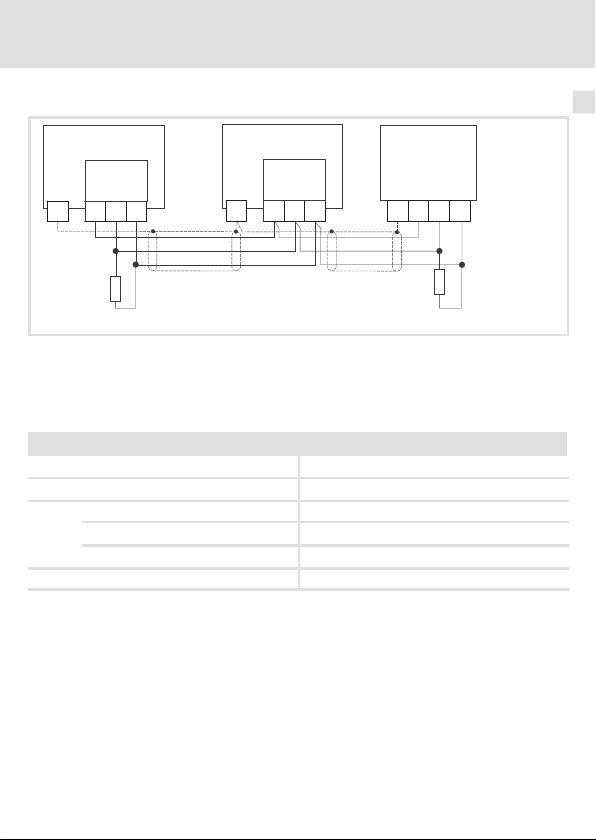
Verdrahtung mit einem Leitrechner
Verdrahtung mit einem Leitrechner
Abb. 1 Prinzipieller Aufbau
Spezifikation des Übertragungskabels
Wir empfehlen CAN-Kabel nach ISO 11898-2 zu verwenden:
CAN-Kabel nach ISO 11898-2
Kabeltyp Paarverseilt mit Abschirmung
Impedanz
Leitungswiderstand/-querschnitt
Kabellänge≤300 m≤70 mΩ/m / 0.25 … 0.34 mm2(AWG22)
Kabellänge 301 … 1000 m
Signallaufzeit
120Ω(95 ... 140Ω)
≤
40 mΩ/m / 0.5 mm2(AWG20)
≤
5 ns/m
6
E82ZAFC013
EDK82ZAFCC-200 DE/EN/FR 4.0
19
Page 20
6 Elektrische Installation
Daten der Anschlussklemmen
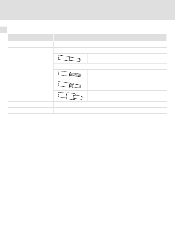
Daten der Anschlussklemmen
Bereich Werte
Elektrischer Anschluss Klemmenleistemit Schraubanschluss
Anschlussmöglichkeiten
Anzugsmoment 0.22 ... 0.25 Nm (1.9 ... 2.2 lb-in)
Abisolierlänge 5 mm
starr:
flexibel:
1.5 mm2(AWG 16)
ohne Aderendhülse
1.0 mm2(AWG 18)
mit Aderendhülse, ohne Kunststoffhülse
0.5 mm2(AWG 20)
mit Aderendhülse, mit Kunststoffhülse
0.5 mm2(AWG 20)
20
EDK82ZAFCC-200 DE/EN/FR 4.0
Page 21
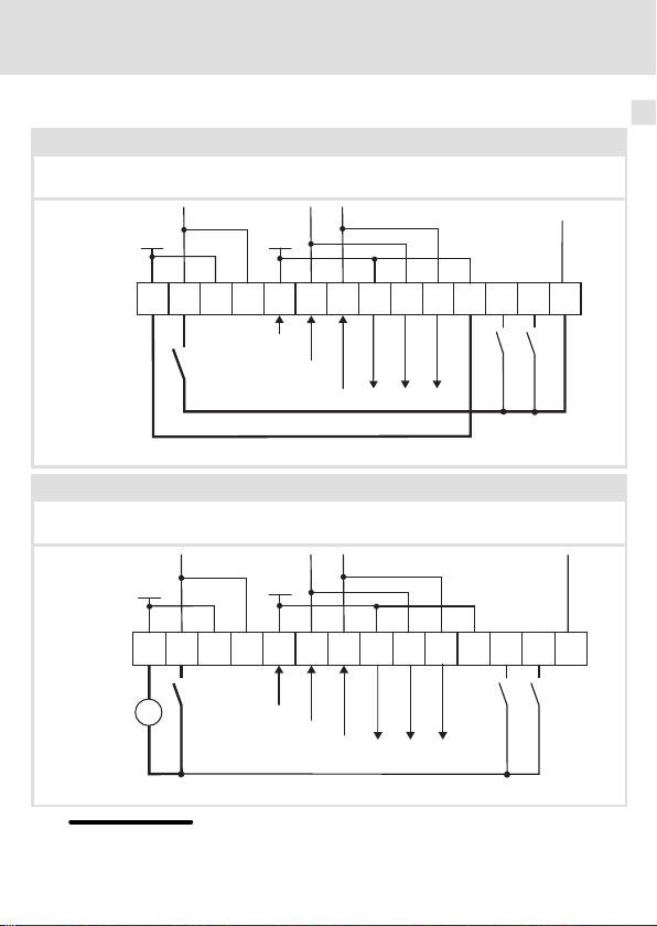
Belegung der Anschlussklemmen
GND1
+20V
39 28 39 287LO HI7LO HI 7
E1
E2
20
CAN-GND
CAN-LOW
CAN-HIGH
X3
GND2
CAN-GND
CAN-LOW
CAN-HIGH
+
_
24V
ext.
+20V
GND2
39 28 39 28
7
LO HI
7
LO HI 7 20
X3
E1
E2
GND1
Versorgung über die interne Spannungsquelle (X3/20)
X3/28, Reglersperre (CINH)
X3/E1 und X3/E2, digitale Eingänge
Versorgung über eine externe Spannungsquelle
X3/28, Reglersperre (CINH)
X3/E1 und X3/E2, digitale Eingänge
Elektrische Installation
Belegung der Anschlussklemmen
E82ZAFC235
6
EDK82ZAFCC-200 DE/EN/FR 4.0
Für den Betrieb notwendige Mindestverdrahtung
E82ZAFC231
21
Page 22

6 Elektrische Installation
Belegung der Anschlussklemmen
Klemme
X3/
39 GND2 Bezugspotenzial 2 der Reglersperre (CINH) an X3/28
28 CINH Reglersperre
7 GND1 Bezugspotenzial1
LO CAN-LOW CAN-Datenleitung (LOW)
HI CAN-HIGH CAN-Datenleitung (HIGH)
E1, E2 Digitale Ein-
20 Spannungsquelle zur internen Versorgung
Bezeichnung Funktion / Pegel
Eingangswiderstand: 3.3 k
Start = HIGH (12 ... 30 V DC)
Stopp = LOW (0 ... 3 V DC)
Bezug: GND2
Externe Versorgung mit U
Interne Versorgung über Klemme X3/20
gänge
Anwenderdefiniert
Eingangswiderstand: 3.3 k
0 = LOW (0 ... 3 V) SPS-Pegel, HTL
1 = HIGH (12 ... 30 V) SPS-Pegel, HTL
Bezug: GND2
E1 ist wahlweise auch als Frequenzeingang nutzbar (0 ... 10 kHz,
einspurig oder 0 ... 1 kHz zweispurig, Konfiguration über C0425).
U
= 20 V DC
int
I
= 30 mA
max
Bezug: GND1
Ω
= 12 V DC - 0 % ... 30 V DC + 0 %
ext
Ω
22
EDK82ZAFCC-200 DE/EN/FR 4.0
Page 23

Elektrische Installation
Busleitungslänge
Busleitungslänge
Halten Sie die zulässigen Leitungslängen unbedingt ein.
1. Überprüfen Sie die Einhaltung der Gesamt-Leitungslänge in Tab. 1.
Durch die Übertragungsrate ist die Gesamt-Leitungslänge festgelegt.
Übertragungsrate [kBit/s] Max. Buslänge [m]
20 3900
50 1500
125 590
250 250
500 80
Tab. 1 Gesamt-Leitungslänge
2. Überprüfen Sie die Einhaltung der Segment-Leitungslänge in Tab. 2.
Die Segment-Leitungslänge wird durch den verwendeten Leitungsquerschnitt und die Teil-
nehmeranzahl festgelegt. Ohne Repeater ist die Segment-Leitungslänge gleich der Gesamt-Leitungslänge.
Leitungsquerschnitt
2
Teilnehmer
2 240 m 430 m 650 m 940 m
5 230 m 420 m 640 m 920 m
10 230 m 410 m 620 m 900 m
20 210 m 390 m 580 m 850 m
32 200 m 360 m 550 m 800 m
63 170 m 310 m 470 m 690 m
Tab. 2 Segment-Leitungslänge
0.25 mm
0.5 mm
2
0.75 mm
2
1.0 mm
2
6
EDK82ZAFCC-200 DE/EN/FR 4.0
23
Page 24

6 Elektrische Installation
Busleitungslänge
3. Vergleichen Sie die beiden ermittelten Werte miteinander.
Wenn der aus Tab. 2 ermittelte Wert kleiner als die zu realisierende Gesamt-Leitungslänge
aus Tab. 1 sein sollte, müssen Repeater eingesetzt werden. Repeater unterteilen die Gesamt-Leitungslänge in Segmente.
Hinweis!
ƒ
Beachten Sie die Reduzierung der Gesamt-Leitungslänge aufgrund der
Signalverzögerung des Repeaters (siehe Beispiel25).
ƒ
Mischbetrieb liegt vor,
– wenn verschiedene Teilnehmer an einem Netz betrieben werden.
– wenn bei gleicher Übertragungsrate die zugehörigen
Gesamt-Leitungslängen der Teilnehmer unterschiedlich sind, muss zur
Bestimmung der max. Leitungslänge der kleinere Wert verwendet
werden.
Beispiel: Auswahlhilfe
Vorgaben
Leitungsquerschnitt:
Teilnehmeranzahl:
Repeater:
Bei max. Teilnehmeranzahl (63) sind aus den Vorgaben folgende Leitungslängen / Anzahl
Repeater einzuhalten:
Übertragungsrate [kBit/s] 20 50 125 250 500
Max. Leitungslänge [m] 3900 1500 590 250 80
Segment-Leitungslänge [m] 310 310 310 250 80
Anzahl der Repeater 13 5 1 - -
0.5 mm2(gemäß Kabel-Spezifikation 19)
63
Lenze-Repeater, Typ 2176 (Leitungsreduzierung: 30 m)
24
EDK82ZAFCC-200 DE/EN/FR 4.0
Page 25

Elektrische Installation
Busleitungslänge
Repeater-Einsatz prüfen
Vorgaben
Übertragungsrate:
Leitungsquerschnitt:
Teilnehmeranzahl:
Leitungslänge:
Prüfschritte Leitungslänge Siehe
1. Gesamt-Leitungslängebei 125 kBit/s: 590 m aus Tab. 1
2. Segment-Leitungslänge für 28 Teilnehmer und einem Leitungsquerschnitt von 0.5 mm2:
3. Vergleich:Der Wert in Pkt. 2 ist kleiner als die zu realisierende Leitungslänge von 450 m.
Folgerung
Ohne Repeater-Einsatz ist die zu realisierende Leitungslänge von 450 m nicht möglich.
Es muss ein Repeater nach 360 m (Pkt. 2.) eingesetzt werden.
Ergebnis
Verwendet wird der Lenze-Repeater, Typ 2176 (Leitungsreduzierung: 30 m)
Berechnung der max. Leitungslänge:
Erste Segment: 360 m
Zweite Segment: 360 m (entsprechend Tab. 1) minus 30 m (Leitungsreduzierung bei Einsatz eines
Repeaters)
Max. erreichbare Leitungslänge mit einem Repeater: 690 m.
Damit ist die vorgegebene Leitungslänge realisierbar.
125 kBit/s
0.5 mm
28
450 m
2
360 m aus Tab. 2
6
Hinweis!
Die Verwendung eines weiteren Repeaters wird empfohlen als
ƒ
Service-Schnittstelle
Vorteil:
ƒ
EDK82ZAFCC-200 DE/EN/FR 4.0
Störungsfreies Ankoppeln im laufenden Bus-Betrieb möglich.
Einmess-Schnittstelle
Vorteil:
Einmess-/Programmiergerät bleibt galvanisch getrennt.
25
Page 26

7 Inbetriebnahme
1 6
ON
273 84 9510
Einstellmöglichkeiten durch DIP-Schalter
7 Inbetriebnahme
Einstellmöglichkeiten durch DIP-Schalter
ON
OFF
Über die frontseitig angeordneten DIP-Schalter können eingestellt werden:
ƒ Knotenadresse (Schalter 1 ... 6)
ƒ Übertragungsrate (Schalter 7 ... 9)
Der Schalter 10 hat keine Funktion.
Die Lenze-Einstellung aller DIP-Schalter ist OFF.
Hinweis!
Einstellungen über Codestellen
ƒ
In der Lenze-Einstellung (alle SchalterOFF) werden die Werte aus den
Codestellen C0350 (Knotenadresse) und C0351 (Übertragungsrate)
übernommen.
ƒ
Übernahme von Codestellen-Änderungen durch:
– Aus- und wieder Einschalten der Spannungsversorgung oder
– ”Reset Node” mit C0358 = 1
ƒ
C0350 ist inaktiv, wenn vor einem erneuten Netzeinschalten mindestens
ein Schalter 1 ... 6 in Stellung ON gesetzt wurde.
ƒ
C0351 ist inaktiv, wenn vor einem erneuten Netzeinschalten mindestens
ein Schalter 7 ... 9 in Stellung ON gesetzt wurde.
ƒ
Ausführliche Informationen zu den Codestellen finden Sie im
Kommunikationshandbuch CAN und der Dokumentation des
Grundgerätes.
26
EDK82ZAFCC-200 DE/EN /FR 4.0
Page 27

Einstellmöglichkeiten durch DIP-Schalter
Inbetriebnahme
Knotenadresse einstellen
ƒ Die Knotenadressen bei mehreren vernetzten CAN-Teilnehmern müssen sich
voneinander unterscheiden.
ƒ Alle in Stellung ON befindlichen Schalter (1 ... 6) ergeben in der Summe der
Wertigkeiten die gewünschte Knotenadresse.
Beispiel
Schalter Wertigkeit
1 32 OFF
2 16 ON
3 8 OFF
4 4 ON
5 2 ON
6 1 ON
Hinweis!
Schalten Sie die Spannungsversorgung des Funktionsmoduls/Grundgerätes
aus und anschließend wieder ein, um geänderte Einstellungen zu aktivieren.
Schaltzustand Knotenadresse
16 + 4 + 2 + 1 = 23
7
EDK82ZAFCC-200 DE/EN /FR 4.0
27
Page 28

7 Inbetriebnahme
Einstellmöglichkeiten durch DIP-Schalter
Übertragungsrate einstellen
ƒ Die Übertragungsrate muss bei allen CAN-Teilnehmern identisch eingestellt werden.
ƒ Folgende Übertragungsraten können eingestellt werden:
Übertragungsrate [kBit/s]
7 8 9
20 ON OFF ON
50 OFF ON ON
125 OFF ON OFF
250 OFF OFF ON
500 OFF OFF OFF
Hinweis!
Schalten Sie die Spannungsversorgung des Funktionsmoduls/Grundgerätes
aus und anschließend wieder ein, um geänderte Einstellungen zu aktivieren.
Schalter
28
EDK82ZAFCC-200 DE/EN /FR 4.0
Page 29

Vor dem ersten Einschalten
Stop!
Bevor Sie das Grundgerät mit Funktionsmodul erstmalig im
Systembus-Netzwerk CAN einschalten, überprüfen Sie
ƒ
die gesamte Verdrahtung auf Vollständigkeit, Kurzschluss und Erdschluss.
ƒ
ob das Bussystem beim physikalisch ersten und letzten Busteilnehmer
abgeschlossen ist.
Inbetriebnahme
Vor dem ersten Einschalten
7
EDK82ZAFCC-200 DE/EN/FR 4.0
29
Page 30

7 Inbetriebnahme
Erstes Einschalten
Erstes Einschalten
Hinweis!
ƒ
Mit der Codestelle C0356/x sind die Zeiten für das
einstellbar.
ƒ
Die im Antriebsregler gespeicherten Lenze-Codestellen sind vom
CAN-Master über den Index erreichbar.
Index = 24575 – Lenze-Codestellennummer (Cxxxx)
ƒ
Das Grundgerät ist nur funktionsfähig, wenn ein HIGH-Pegel an der
Klemme 28 des Funktionsmoduls anliegt (Reglerfreigabe über Klemme).
– Beachten Sie, dass die Reglersperre über mehrere Quellen gesetzt
werden kann. Die Quellen wirken wie eine Reihenschaltung von
Schaltern.
– Wenn der Antrieb trotz Reglerfreigabe über Klemme 28 nicht anläuft,
überprüfen Sie, ob noch über eine andere Quelle die Reglersperre
gesetzt ist. Eine andere Quelle könnte z. B. die-Taste des Keypad
sein.
Schritt Beschreibung
1. Leitsystem (CAN-Master) für die Kommunikation mit dem Funktionsmodul konfigurie-
2. Grundgerät über Klemme 28 (CINH) sperren.
3. Netzspannung zuschalten.
ren.
Klemme 28 auf LOW-Pegel legen.
Das Grundgerät kann später über den Bus gesperrt und freigegeben werden.
Das Grundgerät ist nach ca. 1 Sekunde betriebsbereit.
Die Reglersperre ist aktiv.
Reaktion des Grundgerätes
Die grüne LED blinkt.
Keypad:
(wenn aufgesteckt)
zyklische
Senden
30
EDK82ZAFCC-200 DE/EN/FR 4.0
Page 31

Inbetriebnahme
Erstes Einschalten
7
4.
5. Sie können jetzt mit dem Grundgerät kommunizieren,d. h. alle Codestellen lesen und
6. Sollwertquelle konfigurieren.
7. Der Master setzt den Systembus (CAN) in den Zustand ”Operational”.
8. Sollwert vorgeben.
9. Sync-Telegramm senden.
10. Grundgerät über Klemme 28 (CINH) freigeben.
11. Der Antrieb läuft jetzt an.
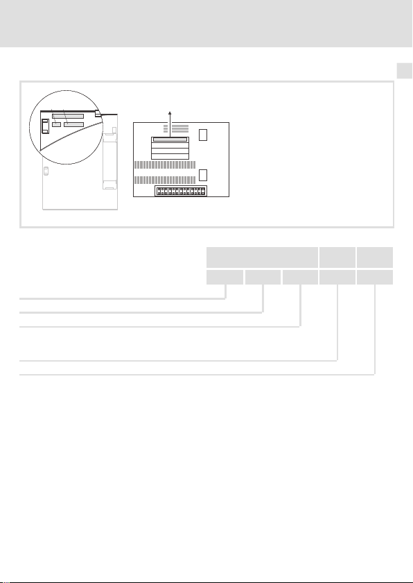
BeschreibungSchritt
A Knotenadresse einstellen über ...
– C0350 oder
– DIP-Schalter (wenn vorhanden).
(Lenze-Einstellung: 500 kBit/s)
Jede Knotenadresse in einem CAN-Netzwerk darf nur einmal verwendet werden.
B Übertragungsrate einstellen über ...
– C0351 oder
– DIP-Schalter (wenn vorhanden).
(Lenze-Einstellung: 1)
Die Übertragungsrate muss bei allen CAN-Teilnehmern identisch eingestellt
werden.
Änderungen werden erst nach dem Befehl ”Reset-Node” (C0358 = 1) übernommen.
alle beschreibbaren Codestellen an Ihre Anwendung anpassen.
C0412/1 = 20 ... 23: Die Sollwertquelle ist ein Wort des Prozessdaten-Kanals 1
(CAN1).
z. B. C0412/1 = 21: die Sollwertquelle ist CAN-IN1.W2
Den Sollwert über das ausgewählte CAN-Wort (z. B. CAN-IN1.W2) senden.
Das Sync-Telegramm wird vom CAN-Teilnehmer nur empfangen, wenn C0360 = 1
ist.
Lenze-Einstellung: Sync-Steuerung
Klemme 28 auf HIGH-Pegel legen.
EDK82ZAFCC-200 DE/EN/FR 4.0
31
Page 32

7 Inbetriebnahme
Basisidentifier der CAN-Objekte
Basisidentifier der CAN-Objekte
Das CAN-Bussystem ist nachrichtenorientiert und nicht teilnehmerorientiert. Jede Nachricht hat eine eindeutige Kennung, den Identifier. Bei CANopen wird eine Teilnehmerorientierung dadurch erreicht, dass es für jede Nachricht nur einen Sender gibt.
Mit Ausnahme des Netzwerkmanagements und des Sync-Telegramms enthält der Identifier die Knotenadresse des Antriebs:
Identifier (COB-ID) = Basis-Identifier + einstellbare Knotenadresse (Node-ID)
Die Identifier-Vergabe ist im CANopen-Protokoll festgelegt.
Der Basisidentifier ist entsprechend der CANopen-Spezifikation ab Werk mit folgenden
Werten voreingestellt:
Objekt
NMT 0 0
Sync 128 80
TPDO 1
(CAN-OUT1)
PDO1
RPDO1
(CAN-IN1)
TPDO2
(CAN-OUT2)
PDO2
RPDO2
(CAN-IN2)
SDO1
SDO2
PDO Sync-gesteuert oder zeitgesteuert über C0360 konfigurieren
Sync-gesteuert
zeitgesteuert
Sync-gesteuert
zeitgesteuert
zeitgesteuert
zeitgesteuert
Richtung Basisidentifier
vom Antrieb zum Antrieb dec hex
X
X
X 641 281
X 640 280
X 1408 580
X 1536 600
X 1472 5C0
X 1600 640
384 180
769 301
512 200
768 300
32
EDK82ZAFCC-200 DE/EN/FR 4.0
Page 33

Basisidentifier der CAN-Objekte
Inbetriebnahme
7
EDK82ZAFCC-200 DE/EN/FR 4.0
33
Page 34

Legend for fold-out page
Pos. Description Detailed
DIP switches for setting the
node address (switches 1 ... 6)
baud rate (switches 1 ... 7)
Terminal strip X3, connection for
system bus (CAN)
controller inhibit (CINH)
Nameplate
0Fig.0Tab. 0
information
56
51
43
34
EDK82ZAFCC-200 DE/EN/FR 4.0
Page 35

Contents i
1 About this documentation 36. . . . . . . . . . . . . . . . . . . . . . . . . . . . . . . . . . . . . . . . . . .
Conventions used 37. . . . . . . . . . . . . . . . . . . . . . . . . . . . . . . . . . . . . . . . . . . . . . . . . .
Notes used 38. . . . . . . . . . . . . . . . . . . . . . . . . . . . . . . . . . . . . . . . . . . . . . . . . . . . . . . .
2 Safety instructions 40. . . . . . . . . . . . . . . . . . . . . . . . . . . . . . . . . . . . . . . . . . . . . . . . .
3 Product description 41. . . . . . . . . . . . . . . . . . . . . . . . . . . . . . . . . . . . . . . . . . . . . . . . .
Application as directed 41. . . . . . . . . . . . . . . . . . . . . . . . . . . . . . . . . . . . . . . . . . . . . .
Scope of supply 42. . . . . . . . . . . . . . . . . . . . . . . . . . . . . . . . . . . . . . . . . . . . . . . . . . . .
Identification 43. . . . . . . . . . . . . . . . . . . . . . . . . . . . . . . . . . . . . . . . . . . . . . . . . . . . . .
4 Technical data 44. . . . . . . . . . . . . . . . . . . . . . . . . . . . . . . . . . . . . . . . . . . . . . . . . . . . .
General Data 44. . . . . . . . . . . . . . . . . . . . . . . . . . . . . . . . . . . . . . . . . . . . . . . . . . . . . .
Operating conditions 44. . . . . . . . . . . . . . . . . . . . . . . . . . . . . . . . . . . . . . . . . . . . . . .
Protective insulation 45. . . . . . . . . . . . . . . . . . . . . . . . . . . . . . . . . . . . . . . . . . . . . . . .
Connection terminals 45. . . . . . . . . . . . . . . . . . . . . . . . . . . . . . . . . . . . . . . . . . . . . .
Dimensions 47. . . . . . . . . . . . . . . . . . . . . . . . . . . . . . . . . . . . . . . . . . . . . . . . . . . . . . .
5 Mechanical installation 48. . . . . . . . . . . . . . . . . . . . . . . . . . . . . . . . . . . . . . . . . . . . .
6 Electrical installation 49. . . . . . . . . . . . . . . . . . . . . . . . . . . . . . . . . . . . . . . . . . . . . . .
Wiring according to EMC 49. . . . . . . . . . . . . . . . . . . . . . . . . . . . . . . . . . . . . . . . . . . .
Wiring to a host 50. . . . . . . . . . . . . . . . . . . . . . . . . . . . . . . . . . . . . . . . . . . . . . . . . . . .
Connection terminals 51. . . . . . . . . . . . . . . . . . . . . . . . . . . . . . . . . . . . . . . . . . . . . .
Assignment of the terminals 52. . . . . . . . . . . . . . . . . . . . . . . . . . . . . . . . . . . . . . . . .
Bus cable length 54. . . . . . . . . . . . . . . . . . . . . . . . . . . . . . . . . . . . . . . . . . . . . . . . . . .
7 Commissioning 57. . . . . . . . . . . . . . . . . . . . . . . . . . . . . . . . . . . . . . . . . . . . . . . . . . . .
Possible settings via DIP switch 57. . . . . . . . . . . . . . . . . . . . . . . . . . . . . . . . . . . . . .
Before switching on 60. . . . . . . . . . . . . . . . . . . . . . . . . . . . . . . . . . . . . . . . . . . . . . . .
Initial switch-on 61. . . . . . . . . . . . . . . . . . . . . . . . . . . . . . . . . . . . . . . . . . . . . . . . . . .
Basic identifiers of the CAN objects 63. . . . . . . . . . . . . . . . . . . . . . . . . . . . . . . . . . .
EDK82ZAFCC-200 DE/EN /FR 4.0
35
Page 36

1 About this documentation
1 Aboutthis documentation
Contents
This documentation includes ...
ƒ Safety instructions which you must observe in any case;
ƒ Data about the versions of Lenze basic devices to be used;
ƒ Information about the mechanical and electrical installation of the function module;
ƒ Information about the commissioning of the function module;
ƒ Technical data.
Tip!
More information about this function module is available in the corresponding
communication manual.
The PDF file can be downloaded from the Internet in the ”Services &
Downloads” area at
http://www.Lenze.com
Target group
This documentation is intended for persons who install and commission the described
product according to the project requirements.
Validity information
The information given in this documentation is valid for the following devices:
Function module Type designation From hardware version
CAN-I/O E82ZAFCC20x 3A
Tip!
Documentation and software updates for further Lenze products can be found
on the Internet in the ”Services & Downloads” area under
http://www.Lenze.com
36
EDK82ZAFCC-200 DE/EN/FR 4.0
Page 37

About this documentation
Conventions used
Conventions used
This documentation uses the following conventions to distinguish between differenttypes
of information:
Type of information Identification Examples/notes
Numbers
Decimal separator Point The decimal point is used throughout
Symbols
Page reference
this documentation.
Example: 1234.56
Reference to another page with
additional information
Example:16 = see page 16
1
EDK82ZAFCC-200 DE/EN/FR 4.0
37
Page 38

1 About this documentation
Notes used
Notes used
The following pictographs and signal words are used in this documentation to indicate
dangers and important information:
Safety instructions
Structure of safety instructions:
Danger!
(characterises the type and severity of danger)
Note
(describes the danger and gives information about how to prevent dangerous
situations)
Pictograph and signal word Meaning
Danger of personal injury through dangerous electrical
voltage.
Danger!
Danger!
Stop!
Reference to an imminent danger that may result in
death or serious personal injury if the corresponding
measures are not taken.
Danger of personal injury through a general source of
danger.
Reference to an imminent danger that may result in
death or serious personal injury if the corresponding
measures are not taken.
Danger of property damage.
Reference to a possible danger that may result in
property damage if the corresponding measures are not
taken.
38
EDK82ZAFCC-200 DE/EN/FR 4.0
Page 39

Application notes
Pictograph and signal word Meaning
About this documentation
Notes used
1
Note!
Tip!
Important note to ensure troublefree operation
Useful tip for simple handling
Reference to another documentation
EDK82ZAFCC-200 DE/EN/FR 4.0
39
Page 40

2 Safety instructions
2 Safetyin structions
Danger!
Inappropriate handling of the function module and the standard device can
cause serious injuries to persons and damage to material assets.
Observe the safety instructions and residual hazards included in the
documentation of the standard device.
Stop!
Electrostatic discharge
Electronic components within the function module can be damaged or
destroyed by electrostatic discharge.
Possible consequences:
ƒ
The function module is defective.
ƒ
Fieldbus communication is not possible or faulty.
Protective measures
ƒ
Free yourself from any electrostatic charge before you touch the module.
40
EDK82ZAFCC-200 DE/EN/FR 4.0
Page 41

Product description
Application as directed
3 Productdescription
Application as directed
The function module ...
ƒ connects the Lenze frequency inverter to the CAN communication system.
ƒ is a device to be used in industrial power systems.
ƒ is an accessory module which can be used with the following Lenze frequency
inverters:
Device type From version
Frequency inverter
Drive PLC Drive PLC 1x20
8200 vector Vx21
8200 motec Vx21
3
EDK82ZAFCC-200 DE/EN/FR 4.0
41
Page 42

3 Product description
1 2 3 4
5
7 7 7 E1
LO LO
28 E2 2028
HI HI
3939
Adress
Bd
12 3 45678 9 10
Scope of supply
Scope of supply
Pos. Scope of supply
E82ZAFCC200 functionmodule
Mounting Instructions
Screwdriver
Two bus terminating resistors (120Ωeach)
Adhesive tape
E82ZAFC004
42
EDK82ZAFCC-200 DE/EN /FR 4.0
Page 43

Identification
E82AF000P0B201XX
APPLICATION
010/3A22
APPLICATION
010/3A22
L
Type
Id.-No.
Prod.-No.
Ser.-No.
Series
CAN
Generation
Variant
200: uncoated design
201: coated design
Hardware version
Software version
Product description
Identification
E82ZAFX005
E82ZAF C C 20x 3A
3
EDK82ZAFCC-200 DE/EN/FR 4.0
43
Page 44

4 Technical data
General Data
4 Technical data
General Data
Field Values
Order designation E82ZAFCC2xx (xx: see43)
Communication profile Based on CANopen
Communication medium ISO 11898
Network topology
Node addresses Max.63
Baud rate [kbps] 20, 50, 125, 250, 500
Operating conditions
Ambient conditions
Climate
Storage IEC/EN 60721-3-1 1K3 (-25 to +60 °C)
Transport IEC/EN 60721-3-2 2K3 (-25 to +70 °C)
Operation Corresponding to the data of the Lenze standard device used (see
Pollution EN 61800-5-1 Degree of pollution 2
Degree of protection IP20 (protection against accidental contact according to NEMA 250 type 1)
Line (terminated on both sides with a resistance of 120Ω)
documentation of the standard device).
44
EDK82ZAFCC-200 DE/EN/FR 4.0
Page 45

Technical data
Protective insulation
Protective insulation
Insulation between busand ... Type of insulation (in accordance with
Power section
– 8200 vector Reinforced insulation
– 8200 motec Reinforced insulation
Reference earth / PE (X3/7)
Supply for CINH (X3/20)
Controller inhibit, CINH (X3/28)
Connection terminals
Terminal
X3/
39 GND2 Reference potential 2 of the controller inhibit (CINH) at X3/28
28 CINH Controller inhibit
7 GND1 Reference potential 1
LO CAN-LOW CAN data line (LOW)
HI CAN-HIGH CAN data line (HIGH)
E1, E2 Digital inputs User-defined
20 Voltage source for internal supply
Designation Function / level
Input resistance: 3.3 k
Start = HIGH (+12 ... +30 V DC)
Stop = LOW (0 ... +3 V DC)
Reference: GND2
External supply with U
Internal supply via terminal X3/20
Input resistance: 3.3 k
0 = LOW ( 0 ... +3 V) PLC level, HTL
1 = HIGH (+12 ... +30 V) PLC level, HTL
Reference: GND2
E1 can optionally also be used as frequency input (0 ... 10 kHz,
single-track or 0 ... 1 kHz two-track, configuration via C0425).
U
= +20 V DC
int
I
max
Reference: GND1
= 30 mA
EN 61800-5-1)
Functional insulation
Functional insulation
Functional insulation
Ω
= +12 V DC - 0 % ... +30 V DC + 0 %
ext
Ω
4
EDK82ZAFCC-200 DE/EN/FR 4.0
45
Page 46

4 Technical data
1 2 3 4
5
7 7 7 E1
LO LO
28 E2 2028
HI HI
3939
Adress
Bd
12 3 45678 9 10
0
0
0
b
a
c
Dimensions
Dimensions
E82ZAFCC20x function module
a 51 mm
b 64 mm
c 15 mm
E82ZAFC200
46
EDK82ZAFCC-200 DE/EN/FR 4.0
Page 47

Mechanical installation 5
5 Mechanical installation
Follow the notes given in the Mounting Instructions for the standard device for the
mechanical installation of the function module.
The Mounting Instructions for the standard device ...
ƒ are part of the scope of supply and are enclosed with each device.
ƒ provide tips for avoiding damage through improper handling.
ƒ describe the obligatory order of installation steps.
EDK82ZAFCC-200 DE/EN/FR 4.0
47
Page 48

6 Electrical installation
Wiring according to EMC
6 Electricalinstall ation
Wiring according to EMC
For wiring according to EMC requirements observe the following points:
Note!
ƒ
Separate control cables/data lines from motor cables.
ƒ
Connect the shields of control cables/data lines
digital signals.
ƒ
Use an equalizing conductor with a cross-section of at least 16 mm
(reference: PE) to avoid potential differences between the bus nodes.
ƒ
Observe the other notes concerning EMC-compliant wiring given in the
documentation for the standard device.
Procedure for wiring
1. Observe the bus topology, i.e. do not use stubs.
2. Observe notes and wiring instructions in the documents for the control system.
3. Only use cables corresponding to the listed specifications (49).
4. Observe the permissible bus cable length (53)
5. Connect bus terminating resistors of 120 Ω each (scope of supply):
– only to the physically first and last node
– between the terminals CAN-LOW and CAN-HIGH
.
at both ends
in the case of
2
48
EDK82ZAFCC-200 DE/EN/FR 4.0
Page 49

Electrical installation
7
7
GND
8200vector
8200vector
SPS/PC
E82ZAFCCxxx
E82ZAFCCxxx
120
120
LO
LO
LO
HI
HI
HI
+
+
+
Wiring to a host
Wiring to a host
Fig. 1 Basic structure
Specification of the transmissioncable
We recommend the use of CAN cables in accordance with ISO 11898-2:
CAN cable in accordance withISO 11898-2
Cable type Paired with shielding
Impedance
Cable resistance/cross-section
Cable length≤300 m≤70 mΩ/m / 0.25 … 0.34 mm2(AWG22)
Cable length 301 … 1000 m
Signal propagation delay
120Ω(95 ... 140Ω)
≤
40 mΩ/m / 0.5 mm2(AWG20)
≤
5 ns/m
6
E82ZAFC013
EDK82ZAFCC-200 DE/EN/FR 4.0
49
Page 50

6 Electrical installation
Connection terminals
Connection terminals
Range Values
Electrical connection Terminal strip with screw connection
Possible connections
Tightening torque 0.22 ... 0.25 Nm (1.9 ... 2.2 lb-in)
Bare end 5 mm
rigid:
flexible:
1.5 mm2(AWG 16)
without wire end ferrule
1.0 mm2(AWG 18)
with wire end ferrule, without plastic sleeve
0.5 mm2(AWG 20)
with wire end ferrule, with plastic sleeve
0.5 mm2(AWG 20)
50
EDK82ZAFCC-200 DE/EN/FR 4.0
Page 51

Assignment of the terminals
GND1
+20V
39 28 39 287LO HI7LO HI 7
E1
E2
20
CAN-GND
CAN-LOW
CAN-HIGH
X3
GND2
CAN-GND
CAN-LOW
CAN-HIGH
+
_
24V
ext.
+20V
GND2
39 28 39 28
7
LO HI
7
LO HI 7 20
X3
E1
E2
GND1
Supply via the internal voltage source (X3/20)
X3/28, controller inhibit (CINH)
X3/E1 and X3/E2, digital inputs
Supply via an external voltage source
X3/28, controller inhibit (CINH)
X3/E1 and X3/E2, digital inputs
Electrical installation
Assignment of the terminals
E82ZAFC235
6
EDK82ZAFCC-200 DE/EN/FR 4.0
Minimum wiring required for operation
E82ZAFC231
51
Page 52

6 Electrical installation
Assignment of the terminals
Terminal
X3/
39 GND2 Reference potential 2 of the controller inhibit (CINH) at X3/28
28 CINH Controller inhibit
7 GND1 Reference potential 1
LO CAN-LOW CAN data line (LOW)
HI CAN-HIGH CAN data line (HIGH)
E1, E2 Digital inputs User-defined
20 Voltage source for internal supply
Designation Function / level
Input resistance: 3.3 k
Start = HIGH (+12 ... +30 V DC)
Stop = LOW (0 ... +3 V DC)
Reference: GND2
External supply with U
Internal supply via terminal X3/20
Input resistance: 3.3 k
0 = LOW ( 0 ... +3 V) PLC level, HTL
1 = HIGH (+12 ... +30 V) PLC level, HTL
Reference: GND2
E1 can optionally also be used as frequency input (0 ... 10 kHz,
single-track or 0 ... 1 kHz two-track, configuration via C0425).
U
= +20 V DC
int
I
= 30 mA
max
Reference: GND1
Ω
= +12 V DC - 0 % ... +30 V DC + 0 %
ext
Ω
52
EDK82ZAFCC-200 DE/EN/FR 4.0
Page 53

Electrical installation
Bus cable length
Bus cable length
It is absolutely necessary to comply with the permissible cable lengths.
1. Check the compliance with the total cable length in Tab. 1.
The total cable length is defined by the baud rate.
Baud rate [kbps] Max. bus length [m]
20 3900
50 1500
125 590
250 250
500 80
Tab. 1 Total cable length
2. Check the compliance with the segment cable length in Tab. 2.
The segment cable length is defined by the cable cross-section used and the number of
nodes. Without any repeaters, the segment cable length corresponds to the total cable
length.
Cable cross-section
2
Node
2 240 m 430 m 650 m 940 m
5 230 m 420 m 640 m 920 m
10 230 m 410 m 620 m 900 m
20 210 m 390 m 580 m 850 m
32 200 m 360 m 550 m 800 m
63 170 m 310 m 470 m 690 m
Tab. 2 Segment cable length
0.25 mm
0.5 mm
2
0.75 mm
2
1.0 mm
2
6
EDK82ZAFCC-200 DE/EN/FR 4.0
53
Page 54

6 Electrical installation
Bus cable length
3. Compare both values.
If the value given in Tab. 2 is smaller than the required total cable length given in Tab. 1,
repeaters must be used. Repeaters divide the total cable length into segments.
Note!
ƒ
Please note the reduction of the total cable length due to the signal delay
of the repeater (see example
ƒ
There is mixed operation if
– different node devices are connected to the same mains.
– the total cable lengths of the nodes are different at the same baud rate,
the smaller value must be used to determine the max. cable length.
Example: Selection help
Given:
Cable cross-section:
Number of nodes:
Repeater:
At maximum number of nodes (63) the following cable lengths/number of repeaters must
be complied with:
Baud rate [kbps] 20 50 125 250 500
Max. cable length [m] 3900 1500 590 250 80
Segment cable length [m] 310 310 310 250 80
Number of repeaters 13 5 1 - -
0.5 mm2(according to cable specification49)
63
Lenze repeater, type 2176 (cable reduction: 30 m)
Check repeater application
Given:
Baud rate:
Cable cross-section:
Number of nodes:
Cable length:
125 kbps
0.5 mm
28
450 m
54
).
2
54
EDK82ZAFCC-200 DE/EN/FR 4.0
Page 55

Electrical installation
Bus cable length
Test sequence Cable length See
1. Totalcable length at 125 kbps: 590 m From Tab. 1
2. Segment cable length for 28 nodes and a cable cross-section
of 0.5 mm2:
3. Comparison:The value under item 2 is smaller than the required cable length of 450 m.
Conclusion
It is not possible to use a cable length of 450 m without a repeater.
After 360 m (item 2.), a repeater must be installed.
Result
The Lenze repeater type 2176 is used (cable reduction: 30 m)
Calculation of the maximum cable length:
First segment: 360 m
Second segment: 360 m (according to Tab. 1)
used)
Maximum possible cable length with repeater: 690 m.
Thus it is possible to use the required cable length.
Note!
minus
30 m (cable reduction when a repeater is
The use of another repeater is recommended as
ƒ
Service interface
Advantage:
Trouble-free connection during running bus operation is
possible.
ƒ
Calibration interface
Advantage:
calibration/programming unit remains electrically isolated.
360 m From Tab. 2
6
EDK82ZAFCC-200 DE/EN/FR 4.0
55
Page 56

7 Commissioning
1 6
ON
273 84 9510
Possible settings via DIP switch
7 Commissioning
Possible settings via DIP switch
The DIP switches on the front serve to set the
ƒ node address (switches 1 ... 6)
ƒ baud rate (switches 7 ... 9)
Switch 10 does not have any function.
The Lenze setting of all DIP switches is OFF.
Note!
Settings via codes
ƒ
In the Lenze setting (all switches OFF), all values from codes C0350 (node
address) and C0351 (baud rate) are accepted.
ƒ
Changes to codes are accepted by:
– A voltage supply switch-off and switch-on or
– A ”Reset node” with C0358 = 1
ƒ
C0350 is inactive if at least one of the switches 1 ... 6 has been set to the
ON position before the mains is reconnected.
ƒ
C0351 is inactive if at least one of the switches 7 ... 9 has been set to the
ON position before the mains is reconnected.
ƒ
Detailed information on the codes is provided in the CAN communication
manual and the documentation of the standard device.
ON
OFF
56
EDK82ZAFCC-200 DE/EN /FR 4.0
Page 57

Possible settings via DIP switch
Commissioning
Node address setting
ƒ In the case of multiple linked CAN nodes, the node addresses must not be identical.
ƒ All switches (1 ... 6) in the ON position result in the desired node address from the
sum of the valencies.
Example
Switch Valency
1 32 OFF
2 16 ON
3 8 OFF
4 4 ON
5 2 ON
6 1 ON
Note!
Switch off the voltage supply of the function module / standard device and
then switch it on again to activate the changed settings.
Switch position Node address
16 + 4 + 2 + 1 = 23
7
EDK82ZAFCC-200 DE/EN /FR 4.0
57
Page 58

7 Commissioning
Possible settings via DIP switch
Baud rate setting
ƒ The baud rate must be identical for all CAN nodes.
ƒ The following baud rates can be set:
Baud rate [kbps]
7 8 9
20 ON OFF ON
50 OFF ON ON
125 OFF ON OFF
250 OFF OFF ON
500 OFF OFF OFF
Note!
Switch off the voltage supply of the function module / standard device and
then switch it on again to activate the changed settings.
Switch
58
EDK82ZAFCC-200 DE/EN /FR 4.0
Page 59

Commissioning
Before switching on
Before switching on
Stop!
Please check the following before you switch on the controller together with
the function module connected to the CAN system bus network:
ƒ
Completeness of the wiring, earth fault and short circuit.
ƒ
Whether the bus system is terminated at the physically first and last node
through the bus terminating resistor.
7
EDK82ZAFCC-200 DE/EN/FR 4.0
59
Page 60

7 Commissioning
Initial switch-on
Initial switch-on
Note!
ƒ
Code C0356/x serves to set the times for
ƒ
The CAN master can access the Lenze codes saved to the controller via the
index.
Index = 24575 – Lenze code number (Cxxxx)
ƒ
The controller is only ready for operation if a HIGH level is applied to
terminal 28 of the function module (controller enable via terminal).
– Please observe that the controller can be inhibited through various
sources. All sources act like a series connection of switches.
– If the drive does not start in spite of the controller enable via terminal
28, check whether the controller is still inhibited via another source such
as the key of the keypad.
Step Description
1. Configure master system (CAN master) for communication with the function module.
2. Inhibit standard device via terminal 28 (CINH).
3. Switch on the mains voltage.
4.
Set terminal 28 to LOW level.
The standard device can be inhibited and enabled via the bus subsequently.
The standard device will be ready for operation after approx. 1 second.
The controller inhibit is active.
Response of standard device
The green LED is blinking.
Keypad:
(if plugged-in)
C Set node address via ...
– C0350 or
– DIP switch (if available).
(Lenze setting: 500 kbps)
A node address ina CAN network must not be used more than once.
D Set baud rate via ...
– C0351 or
– DIP switch (if available).
(Lenze setting: 1)
All CAN nodes must have an identical baud rate.
Changes will not be accepted until a ”Reset node” command (C0358 = 1) has been
executed.
cyclic
transmission.
60
EDK82ZAFCC-200 DE/EN/FR 4.0
Page 61

Commissioning
Initial switch-on
DescriptionStep
5. Communication with the standard device is now possible,i.e. all codes can be read and
6. Configure setpoint source.
7. The master sets the system bus (CAN) to the ”Operational” state.
8. Select setpoint.
9. Transmit sync telegram.
10. Enable standard device via terminal 28 (CINH).
11. Now the drive starts.
all writable codes can be adapted to your application.
C0412/1 = 20 ... 23: The setpoint source is a word of process data channel 1 (CAN1).
e.g. C0412/1 = 21: the setpoint source is CAN-IN1.W2
Transmit the setpoint via the selected CAN word (e.g. CAN-IN1.W2).
The sync telegram is only received by the CAN node if C0360 = 1.
Lenze setting: sync control
Set terminal 28 to HIGH level.
7
EDK82ZAFCC-200 DE/EN/FR 4.0
61
Page 62

7 Commissioning
Basic identifiers of the CAN objects
Basic identifiers of the CAN objects
The CAN bus system is message-oriented. Each message has an unambiguous identifier.
With CANopen, there is only one sender for each message for device-orientation.
Except for the network management and the sync telegram, the identifier contains the
node address of the controller:
Identifier (COB-ID) = basic identifier + adjustable node address (node ID)
The identifier assignment is specified in the CANopen protocol.
The basic identifier in accordance with the CANopen specification ex works is preset to the
following values:
Object
NMT 0 0
Sync 128 80
TPDO 1
(CAN-OUT1)
PDO1
RPDO1
(CAN-IN1)
TPDO2
(CAN-OUT2)
PDO2
RPDO2
(CAN-IN2)
SDO1
SDO2
Configuration of PDO (sync-controlled or time-controlled) via C0360
sync-controlled
time-controlled
sync-controlled
time-controlled
time-controlled
time-controlled
Direction Basic identifier
From the
controller
X
X 641 281
X 1408 580
X 1472 5C0
To the
controller
X
X 640 280
X 1536 600
X 1600 640
Dec Hex
384 180
769 301
512 200
768 300
62
EDK82ZAFCC-200 DE/EN/FR 4.0
Page 63

Basic identifiers of the CAN objects
Commissioning
7
EDK82ZAFCC-200 DE/EN/FR 4.0
63
Page 64

Légende de l’illustration dela page dépliante
Pos. Description Informations
Interrupteur DIP pour réglage de
l’adresse de noeud (interrupteurs 1 à 6)
la vitesse de transmission (interrupteurs 1 ... 7)
Bornier X3, raccordement
du Bus Système CAN
du blocage variateur (CINH)
Plaque signalétique
0Fig.0Tab. 0
détaillées
87
81
73
64
EDK82ZAFCC-200 DE/EN/FR 4.0
Page 65

Sommaire i
1 Présentation du document 66. . . . . . . . . . . . . . . . . . . . . . . . . . . . . . . . . . . . . . . . . . .
Conventions utilisées 67. . . . . . . . . . . . . . . . . . . . . . . . . . . . . . . . . . . . . . . . . . . . . . .
Consignes utilisées 68. . . . . . . . . . . . . . . . . . . . . . . . . . . . . . . . . . . . . . . . . . . . . . . . .
2 Consignes de sécurité 70. . . . . . . . . . . . . . . . . . . . . . . . . . . . . . . . . . . . . . . . . . . . . . .
3 Description du produit 71. . . . . . . . . . . . . . . . . . . . . . . . . . . . . . . . . . . . . . . . . . . . . .
Utilisation conforme à la fonction 71. . . . . . . . . . . . . . . . . . . . . . . . . . . . . . . . . . . . .
Equipement livré 72. . . . . . . . . . . . . . . . . . . . . . . . . . . . . . . . . . . . . . . . . . . . . . . . . . .
Identification 73. . . . . . . . . . . . . . . . . . . . . . . . . . . . . . . . . . . . . . . . . . . . . . . . . . . . . .
4 Spécifications techniques 74. . . . . . . . . . . . . . . . . . . . . . . . . . . . . . . . . . . . . . . . . . .
Caractéristiques générales 74. . . . . . . . . . . . . . . . . . . . . . . . . . . . . . . . . . . . . . . . . .
Conditions d’utilisation 74. . . . . . . . . . . . . . . . . . . . . . . . . . . . . . . . . . . . . . . . . . . . .
Isolement de protection 75. . . . . . . . . . . . . . . . . . . . . . . . . . . . . . . . . . . . . . . . . . . . .
Spécifications des bornes de raccordement 75. . . . . . . . . . . . . . . . . . . . . . . . . . . . .
Encombrements 76. . . . . . . . . . . . . . . . . . . . . . . . . . . . . . . . . . . . . . . . . . . . . . . . . . .
5 Installation mécanique 77. . . . . . . . . . . . . . . . . . . . . . . . . . . . . . . . . . . . . . . . . . . . . .
6 Installation électrique 78. . . . . . . . . . . . . . . . . . . . . . . . . . . . . . . . . . . . . . . . . . . . . . .
Câblage conforme CEM 78. . . . . . . . . . . . . . . . . . . . . . . . . . . . . . . . . . . . . . . . . . . . . .
Raccordement à un maître 79. . . . . . . . . . . . . . . . . . . . . . . . . . . . . . . . . . . . . . . . . . .
Spécifications des bornes de raccordement 80. . . . . . . . . . . . . . . . . . . . . . . . . . . . .
Affectation des bornes de raccordement 81. . . . . . . . . . . . . . . . . . . . . . . . . . . . . . . .
Longueur de câble bus 83. . . . . . . . . . . . . . . . . . . . . . . . . . . . . . . . . . . . . . . . . . . . . .
7 Mise en service 87. . . . . . . . . . . . . . . . . . . . . . . . . . . . . . . . . . . . . . . . . . . . . . . . . . . .
Réglages possibles par interrupteurs DIP 87. . . . . . . . . . . . . . . . . . . . . . . . . . . . . . .
Avant la première mise sous tension 90. . . . . . . . . . . . . . . . . . . . . . . . . . . . . . . . . . .
Première mise en service 91. . . . . . . . . . . . . . . . . . . . . . . . . . . . . . . . . . . . . . . . . . . .
Identificateur de base des objets CAN 93. . . . . . . . . . . . . . . . . . . . . . . . . . . . . . . . . .
EDK82ZAFCC-200 DE/EN /FR 4.0
65
Page 66

1 Présentation du document
1 Présentationdu document
Contenu
La présente documentation contient ...
ƒ des consignes de sécurité à respecter impérativement ;
ƒ les valeurs indiquées concernant les versions des appareils de base Lenze à utiliser ;
ƒ des informations sur l’installation mécanique et électrique du module de fonction ;
ƒ des informations sur la mise en service du module de fonction ;
ƒ les spécifications techniques.
Conseil !
Pour plus d’informations sur ce module de fonction, consulter le manuel de
communication correspondant.
Le fichier PDF peut être téléchargé sur Internet dans la zone ”Services &
Downloads” de notre site à l’adresse suivante :
http://www.Lenze.com
Public visé
Ce document est destiné aux personnes chargées d’installer et de mettre en service le
produit décrit selon les exigences du projet.
Informations relatives à la validité
Les informations contenues dans leprésentdocuments’appliquentaux appareils suivants :
Module de fonction Référence de commande A partir de la version matérielle
CAN-I/O E82ZAFCC20x 3A
Conseil !
Les mises à jour de logiciels et les documentations relatives aux produits Lenze
sont disponibles dans la zone ”Téléchargements” du site Internet :
http://www.Lenze.com
66
EDK82ZAFCC-200 DE/EN/FR 4.0
Page 67

Présentation du document
Conventions utilisées
Conventions utilisées
Pour faire la distinction entre différents types d’informations, ce document utilise les
conventions suivantes :
Type d’information Marquage Exemples/remarques
Représentation des chiffres
Séparateur décimal Point Le point décimal est généralement
Symboles
Renvoi à une page
utilisé.
Exemple : 1234.56
Renvoi à une autre page présentant
des informations supplémentaires
Exemple :16 = voir page 16
1
EDK82ZAFCC-200 DE/EN/FR 4.0
67
Page 68

1 Présentation du document
Consignes utilisées
Consignes utilisées
Pour indiquer des risques et des informations importantes, la présente documentation
utilise les mots et symboles suivants :
Consignes de sécurité
Présentation des consignes de sécurité
Danger !
(Le pictogramme indique le type de risque.)
Explication
(L’explication décrit le risque et les moyens de l’éviter.)
Pictogramme et mot associé Explication
Situation dangereuse pour les personnes en raison d’une
tension électrique élevée
Danger !
Danger !
Stop !
Indication d’un danger imminent qui peut avoir pour
conséquences des blessures mortelles ou très graves en
cas de non-respect des consignes de sécurité
correspondantes
Situation dangereuse pour les personnes en raison d’un
danger d’ordre général
Indication d’un danger imminent qui peut avoir pour
conséquences des blessures mortelles ou très graves en
cas de non-respect des consignes de sécurité
correspondantes
Risques de dégâts matériels
Indication d’un risque potentiel qui peut avoir pour
conséquences des dégâts matériels en cas de non-respect
des consignes de sécurité correspondantes
68
EDK82ZAFCC-200 DE/EN/FR 4.0
Page 69

Consignes d’utilisation
Pictogramme et mot associé Explication
Présentation du document
Consignes utilisées
1
Remarque
importante !
Conseil !
Remarque importante pour assurer un fonctionnement
correct
Conseil utile pour faciliter la mise en oeuvre
Référence à une autre documentation
EDK82ZAFCC-200 DE/EN/FR 4.0
69
Page 70

2 Consignes de sécurité
2 Consignesde sécurité
Danger !
Toute utilisation contre-indiquée du module de fonction et de l’appareil de
base peut entraîner des blessures graves et des dommages matériels.
Tenir compte des consignes de sécurité et des dangers résiduels énoncés dans
la documentation de l’appareil de base.
Stop !
Décharges électrostatiques
Les décharges électrostatiques peuvent endommager ou détruire les
composants électroniques situés à l’intérieur du module de fonction.
Risques encourus :
ƒ
Module de fonction en panne
ƒ
La communication par bus de terrain est impossible ou erronée.
Mesures de protection :
ƒ
Se débarrasser impérativement de toute charge électrostatique avant
toute intervention du le module.
70
EDK82ZAFCC-200 DE/EN/FR 4.0
Page 71

Description du produit
Utilisation conforme à la fonction
3 Descriptiondu produit
Utilisation conforme à la fonction
Le module de fonction ...
ƒ permet de relier le convertisseur de fréquence Lenze au système de communication
CAN.
ƒ est un matériel d’exploitation destiné à être utilisé dans les installations industrielles
à courant fort.
ƒ est un module accessoire compatible avec les convertisseurs de fréquence Lenze
suivants :
Série d’appareils A partir de la version
Convertisseurs de fréquence
API pour entraînements Drive PLC 1x20
8200 vector Vx21
8200 motec Vx21
3
EDK82ZAFCC-200 DE/EN/FR 4.0
71
Page 72

3 Description du produit
1 2 3 4
5
7 7 7 E1
LO LO
28 E2 2028
HI HI
3939
Adress
Bd
12 3 45678 9 10
Equipement livré
Equipement livré
Pos. Contenu de l’emballage
Module de fonctionE82ZAFCC200
Instructions de montage
Tournevis
Résistances d’extrémité de bus (de 120Ωchacune)
Bande autocollante
E82ZAFC004
72
EDK82ZAFCC-200 DE/EN /FR 4.0
Page 73

Identification
E82AF000P0B201XX
APPLICATION
010/3A22
APPLICATION
010/3A22
L
Type
Id.-No.
Prod.-No.
Ser.-No.
Série d’appareils
CAN
Génération d’appareils
Variante
200 : version non enduite
201 : version enduite
Version matérielle
Version logicielle
Description du produit
Identification
E82ZAFX005
E82ZAF C C 20x 3A
3
EDK82ZAFCC-200 DE/EN/FR 4.0
73
Page 74

4 Spécifications techniques
Caractéristiques générales
4 Spécifications techniques
Caractéristiques générales
Domaine Valeurs
Réf. de commande E82ZAFCC2xx (xx : voir73)
Profil de communication Dérivé de CANopen
Support de communication ISO11898
Topologie du réseau
Nombre max. de participants 63
Vitesse de transmission
[kbits/s]
Conditions d’utilisation
Conditions ambiantes
Conditions climatiques
Stockage CEI/EN 60721-3-1 1K3 (-25 ... +60 °C)
Transport CEI/EN 60721-3-2 2K3 (-25 ... +70 °C)
Fonctionnement Conformément aux données de l’appareil de base Lenze utilisé (voir la
Pollution ambiante
admissible
Indice de protection IP20 (protection contre contacts accidentels selon NEMA 250 type 1)
Ligne fermée aux deux extrémités avec 120
20, 50, 125, 250, 500
documentation de l’appareil de base).
EN 61800-5-1 Degré de pollution 2
Ω
74
EDK82ZAFCC-200 DE/EN/FR 4.0
Page 75

Spécifications techniques
Isolement de protection
Isolement de protection
Isolement entre buset... Type d’isolement (selon EN 61800-5-1)
partie puissance
– 8200 vector Isolement renforcé
– 8200 motec Isolement renforcé
= 20 V CC
= 30 mA
Isolement fonctionnel
Isolement fonctionnel
Isolement fonctionnel
Ω
= 12 V CC - 0 % ... 30 V CC + 0 %
ext
Ω
point de terre / PE (X3/7)
alimentation pour CINH (X3/20)
borne de blocage variateur, CINH (X3/28)
Spécifications des bornes de raccordement
Borne X3/
39 GND2 Potentiel de référence 2 de la borne de blocage variateur (CINH) sur
28 CINH Blocage variateur
7 GND1 Potentiel de référence 1
LO CAN-LOW Ligne de données CAN (BAS)
HI CAN-HIGH Ligne de donnéesCAN (HAUT)
E1, E2 Entrées
20 Source de tension pour alimentation interne
Désignation Fonction/Niveau
X3/28
Résistance d’entrée : 3.3 k
Marche = HAUT (12 ... 30 V CC)
Arrêt = BAS (0 ... 3 V CC)
Référence : GND2
Alimentation externe via U
Alimentation interne via borne X3/20
numériques
Spécifique à l’application
Résistance d’entrée : 3.3 k
0 = BAS ( 0 ... 3 V) niveau API, HTL
1 = HAUT (12 ... 30 V) niveau API, HTL
Référence : GND2
E1 peut également être configuré comme entrée fréquence
(0 ... 10 kHz, à une voie ou 0 ... 1 kHz à deux voies, configuration via
C0425).
U
int
I
max
Référence : GND1
4
EDK82ZAFCC-200 DE/EN/FR 4.0
75
Page 76

4 Spécifications techniques
1 2 3 4
5
7 7 7 E1
LO LO
28 E2 2028
HI HI
3939
Adress
Bd
12 3 45678 9 10
0
0
0
b
a
c
Encombrements
Encombrements
Module de fonction E82ZAFCC20x
a 51 mm
b 64 mm
c 15 mm
E82ZAFC200
76
EDK82ZAFCC-200 DE/EN/FR 4.0
Page 77

Installation mécanique 5
5 Installationm écanique
Pour l’installation mécanique du module de fonction,suivreles consignes fournies dans les
instructions de montage de l’appareil de base.
Les instructions de montage de l’appareil de base ...
ƒ font partie de la livraison standard et sont comprises dans l’emballage.
ƒ contiennent des consignes pour éviter des dommages dus à un emploi
contre-indiqué.
ƒ décrivent l’ordre à respecter pour les opérations d’installation.
EDK82ZAFCC-200 DE/EN/FR 4.0
77
Page 78

6 Installation électrique
Câblage conforme CEM
6 Installationé lectrique
Câblage conforme CEM
Pour s’assurer que le câblage est conforme aux exigences à respecter en matière de CEM,
vérifier les points suivants :
Remarque importante !
ƒ
Séparer physiquement les câbles de commande/de données des câbles
moteur.
ƒ
Pour les signaux numériques, blinder les câbles de commande et de
données
ƒ
ƒ
Procédure à suivre pour le câblage
1. Respecter la topologie de bus : ne pas utiliser de câbles de dérivation.
2. Respecter les indications et prescriptions concernant le câblage fournies dans la
documentation du système de commande.
3. Utiliser uniquement des câbles bus correspondant aux spécifications fournies
(79).
4. Respecter la longueur de câble bus max. admissible (83)
5. Connecter des résistances d’extrémité de bus de 120 Ω chacune (comprises dans la
livraison) :
– uniquement entre le premier et le dernier participant au bus (extrémités
physiques) ;
– entre les bornes CAN-LOW (BAS) et CAN-HIGH (HAUT).
aux deux extrémités
Pour éviter les différences de potentiel entre les participants au bus, utiliser
une ligne de compensation d’une section minimale de 16 mm2(référence :
PE).
Respecter les autres consignes relatives au câblage conforme CEM fournies
dans la documentation de l’appareil de base.
.
.
78
EDK82ZAFCC-200 DE/EN/FR 4.0
Page 79

Installation électrique
7
7
GND
8200vector
8200vector
SPS/PC
E82ZAFCCxxx
E82ZAFCCxxx
120
120
LO
LO
LO
HI
HI
HI
+
+
+
Raccordement à un maître
Raccordement à un maître
Fig. 1 Schéma de principe
Spécifications pour câble de transmission
Il est recommandé d’utiliser des câbles CAN conformes à la norme ISO 11898-2 :
Câbles CAN conformes à la norme ISO 11898-2
Type de câble Paire blindée
Impédance
Résistivité et section de câble
Longueur de câble≤300 m≤70 mΩ/m / 0,25 … 0,34 mm2(AWG22)
Longueur de câble 301 … 1000 m
Temps de parcours du signal
120Ω(95 ... 140Ω)
≤
40 mΩ/m / 0,5 mm2(AWG20)
≤
5 ns/m
6
E82ZAFC013
EDK82ZAFCC-200 DE/EN/FR 4.0
79
Page 80

6 Installation électrique
Spécifications des bornes de raccordement
Spécifications des bornes de raccordement
Plage Valeurs
Raccordement électrique Bornieravec fixation par vis
Possibilités de
raccordement
Couple de serrage 0.22 ... 0.25 Nm (1.9 ... 2.2 lb-in)
Longueur du fil dénudé 5 mm
Rigide :
Flexible :
1.5 mm2(AWG 16)
sans embout
1.0 mm2(AWG 18)
avec embout, sans cosse en plastique
0.5 mm2(AWG 20)
avec embout, avec cosse en plastique
0.5 mm2(AWG 20)
80
EDK82ZAFCC-200 DE/EN/FR 4.0
Page 81

Affectation des bornes de raccordement
GND1
+20V
39 28 39 287LO HI7LO HI 7
E1
E2
20
CAN-GND
CAN-LOW
CAN-HIGH
X3
GND2
CAN-GND
CAN-LOW
CAN-HIGH
+
_
24V
ext.
+20V
GND2
39 28 39 28
7
LO HI
7
LO HI 7 20
X3
E1
E2
GND1
Affectation des bornes de raccordement
Alimentation via source de tension interne (X3/20)
X3/28, blocage variateur (CINH)
X3/E1 et X3/E2, entrées numériques
Alimentation via source de tension externe
X3/28, blocage variateur (CINH)
X3/E1 et X3/E2, entrées numériques
Installation électrique
E82ZAFC235
6
EDK82ZAFCC-200 DE/EN/FR 4.0
Câblage min. nécessaire au fonctionnement
E82ZAFC231
81
Page 82

6 Installation électrique
Affectation des bornes de raccordement
Borne X3/
39 GND2 Potentiel de référence 2 de la borne de blocage variateur (CINH) sur
28 CINH Blocage variateur
7 GND1 Potentiel de référence 1
LO CAN-LOW Ligne de données CAN (BAS)
HI CAN-HIGH Ligne de donnéesCAN (HAUT)
E1, E2 Entrées
20 Source de tension pour alimentation interne
Désignation Fonction/Niveau
X3/28
Résistance d’entrée : 3.3 k
Marche = HAUT (12 ... 30 V CC)
Arrêt = BAS (0 ... 3 V CC)
Référence : GND2
Alimentation externe via U
Alimentation interne via borne X3/20
numériques
Spécifique à l’application
Résistance d’entrée : 3.3 k
0 = BAS ( 0 ... 3 V) niveau API, HTL
1 = HAUT (12 ... 30 V) niveau API, HTL
Référence : GND2
E1 peut également être configuré comme entrée fréquence
(0 ... 10 kHz, à une voie ou 0 ... 1 kHz à deux voies, configuration via
C0425).
U
= 20 V CC
int
I
= 30 mA
max
Référence : GND1
Ω
= 12 V CC - 0 % ... 30 V CC + 0 %
ext
Ω
82
EDK82ZAFCC-200 DE/EN/FR 4.0
Page 83

Installation électrique
Longueur de câble bus
Longueur de câble bus
Respecter impérativement les longueurs de câble autorisées !
1. Vérifier la longueur de câble totale admise dans le Tab. 1.
La longueur de câble totale est déterminée par la vitesse de transmission.
Vitesse de transmission
[kbits/s]
20 3900
50 1500
125 590
250 250
500 80
Tab. 1 Longueur de câble totale
2. Vérifier la longueur de câble admise par segment dans le Tab. 2.
La longueur de câble par segment est déterminée par la section de câble utilisée et le
nombre de participants. Sans répétiteur, la longueur de câble par segment équivaut à la
longueur de câble totale.
Nombre de
participants
2 240 m 430 m 650 m 940 m
5 230 m 420 m 640 m 920 m
10 230 m 410 m 620 m 900 m
20 210 m 390 m 580 m 850 m
32 200 m 360 m 550 m 800 m
63 170 m 310 m 470 m 690 m
Tab. 2 Longueur de câble par segment
Section de câble
0,25 mm
Longueur de câble busmaxi[m]
2
0,5 mm
2
0,75 mm
2
1,0 mm
2
6
EDK82ZAFCC-200 DE/EN/FR 4.0
83
Page 84

6 Installation électrique
Longueur de câble bus
3. Comparer les valeurs déterminées.
Si la valeur établie à partir du Tab. 2 est inférieure à la longueur de câble totale à réaliser
d’après le Tab. 1, il est nécessaire d’avoir recours à des répétiteurs. Les répétiteurs divisent
la longueur de câble totale en segments.
Remarque importante !
ƒ
Tenir compte de la réduction de la longueur de câble totale, due à la
temporisation des signaux du répétiteur (voir exemple
ƒ
Fonctionnement mixte
– Il y a fonctionnement mixte lorsque des participants différents sont
raccordés à un même réseau.
– Si la longueur de câble totale pour les différents participants varie,
malgré une vitesse de transmission identique, la longueur de câble maxi
doit être déterminée sur la base de la plus petite valeur.
Exemple : aide à la sélection
Données de base
Section de câble :
Nombre de participants :
Répétiteurs :
0.5 mm2(conformément aux spécifications du câble fournies79)
63
répétiteurs Lenze de type 2176 (réd. de la longueur de câble : 30 m)
Lorsque le nombre max. de participants (63) est atteint, respecter impérativement les
longueurs de câble et le nombre de répétiteurs indiqués ci-dessous :
Vitesse de transmission
[kbits/s]
Longueur de câble max. [m] 3900 1500 590 250 80
Longueur de câble par
segment [m]
Nombre de répétiteurs 13 5 1 - -
20 50 125 250 500
310 310 310 250 80
85
).
84
EDK82ZAFCC-200 DE/EN/FR 4.0
Page 85

Utilisation d’un répétiteur
Configuration requise
Vitesse de transmission
Section de câble
Nombre de participants
Longueur de câble
125 kbits/s
2
0.5 mm
28
450 m
Installation électrique
Longueur de câble bus
6
Etapes de contrôle Longueur de
1. Longueurde câble totale pour 125 kbits/s 590 m Voir Tab. 1
2. Longueurde câble par segment pour 28 participants au bus
et une section de câble de 0.5 mm
3. Analysecomparative : la valeur indiquée au point 2 est inférieure à la longueur de câble
nécessaire, qui est de 450 m.
Conclusion
Sans répétiteur, la longueur de câble nécessaire (450 m) ne peut être réalisée.
Au-delà de 360 m (point 2.), il faut utiliser un répétiteur.
EDK82ZAFCC-200 DE/EN/FR 4.0
2
câble
360 m Voir Tab. 2
Référence
85
Page 86

6 Installation électrique
Longueur de câble bus
Résultat
Répétiteur utilisé : répétiteur Lenze de type 2176 (réduction de la longueur de câble : 30 m)
Calcul de la longueur de câble max. :
Premier segment : 360 m
Second segment : 360 m (selon Tab. 1)
répétiteur)
Longueur de câble max. possible avec un répétiteur : 690 m
La longueur de câble requise peut donc être réalisée.
Remarque importante !
L’utilisation d’un deuxième répétiteur est recommandée en tant que :
ƒ
interface de service
Avantage :
ƒ
interface de mesure
Avantage :
galvaniquement.
couplage possible sans interrompre le fonctionnement par bus
l’appareil de mesure/de programmation reste isolé
moins
30 m (réduction de la longueur de câble avec
86
EDK82ZAFCC-200 DE/EN/FR 4.0
Page 87

Réglages possibles par interrupteurs DIP
1 6
ON
273 84 9510
Mise en service
7 Miseen service
Réglages possibles par interrupteurs DIP
Les interrupteursDIP situés à l’avant de l’appareil permettent de régler :
ƒ l’adresse de noeud (interrupteurs 1 à 6)
ƒ la vitesse de transmission (interrupteurs 7 à 9)
L’interrupteur 10 n’est affecté à aucune fonction.
Réglage Lenze : tous les interrupteurs DIP en position OFF
Remarque importante !
Réglages effectués par modification des codes
ƒ
Si le réglage Lenze est activé (tous les interrupteursen position OFF), les
valeurs réglées en C0350 (adresse de noeud) et C0351 (vitesse de
transmission) sont appliquées.
ƒ
Prise en compte des codes modifiés suite à :
– une brève coupure de l’alimentation, suivie d’une nouvelle mise sous
tension ou
– un ”Reset Node” via C0358 = 1
ƒ
Le code C0350 est désactivé si l’un des interrupteurs1 à 6 est en position
ON avant la nouvelle mise sous tension.
ƒ
Le code C0351 est désactivé si l’un des interrupteurs7 à 9 est en position
ON avant la nouvelle mise sous tension.
ƒ
Pour plus de détailssur les codes, se reporter au manuel de communication
CAN et à la documentation de l’appareil de base.
7
ON
OFF
EDK82ZAFCC-200 DE/EN /FR 4.0
87
Page 88

7 Mise en service
Réglages possibles par interrupteurs DIP
Réglage de l’adresse de nœud
ƒ En cas de fonctionnement en réseau par bus CAN, les différentes adresses de noeud
doivent être univoques.
ƒ L’adresse de noeud voulue se déduit de la somme des valeurs des interrupteurs en
position ON (1...6).
Exemple
Interrupteur Valeur affectée
1 32 OFF
2 16 ON
3 8 OFF
4 4 ON
5 2 ON
6 1 ON
Remarque importante !
Pour activer les réglages modifiés, couper brièvement l’alimentation du
module de fonction / de l’appareil de base puis le remettre sous tension.
Position Adresse de noeud
16 + 4 + 2 + 1 = 23
88
EDK82ZAFCC-200 DE/EN /FR 4.0
Page 89

Réglages possibles par interrupteurs DIP
Mise en service
Réglage de la vitesse de transmission
ƒ La vitesse de transmission réglée doit être identique pour tous les participants au bus
CAN.
ƒ Les vitesses de transmission suivantes sont prises en charge :
Vitesse de transmission
[kbits/s]
20 ON OFF ON
50 OFF ON ON
125 OFF ON OFF
250 OFF OFF ON
500 OFF OFF OFF
Remarque importante !
Pour activer les réglages modifiés, couper brièvement l’alimentation du
module de fonction / de l’appareil de base puis le remettre sous tension.
7 8 9
Interrupteur
7
EDK82ZAFCC-200 DE/EN /FR 4.0
89
Page 90

7 Mise en service
Avant la première mise sous tension
Avant la première mise sous tension
Stop !
Avant la première mise sous tension de l’appareil de base avec le module de
fonction raccordé au Bus Système CAN, vérifier
ƒ
le câblage dans son intégralité afin d’éviter un court-circuit ou un défaut
de mise à la terre ;
ƒ
si une résistance d’extrémité est raccordée au premier et au dernier
participant au bus.
90
EDK82ZAFCC-200 DE/EN/FR 4.0
Page 91

Mise en service
Première mise en service
Première mise en service
Remarque importante !
ƒ
Le code C0356/x permet de régler les temps relatifs aux émissions
cycliques
ƒ
ƒ
Etape Description
1. Configurer le système maître (maître CAN) en vue d’établir la communication avec le
2. Bloquer l’appareil de base via la borne 28 (CINH).
3. Brancher la tension réseau.
.
Les codes Lenze sauvegardés sur le variateur peuvent être consultés par le
maître CAN via l’index correspondant.
Index = 24575 – Numéro de code Lenze (Cxxxx)
L’appareil de base ne peut fonctionner que si la borne 28 est sur niveau
HAUT (déblocage variateur par borne).
– Tenir compte du fait que le blocage variateur peut être activé via
plusieurs sources. Toutes les sources de blocage agissent comme des
contacts connectés en série.
– Cas où l’entraînement ne démarre pas en dépit du déblocage du
variateur activé via la borne 28 : vérifier si une autre source de
déblocage du variateur est activée (touche du clavier de commande
par exemple).
module de fonction.
Activer le niveau BAS sur la borne 28.
L’appareil de base pourra être bloqué et débloqué ultérieurement par bus.
L’appareil de base est opérationnel au bout d’env. 1 seconde.
Le blocage variateur est activé.
Réaction de l’appareil de base
La LED verte clignote.
Clavier de commande :
(si enfiché)
7
EDK82ZAFCC-200 DE/EN/FR 4.0
91
Page 92

7 Mise en service
Première mise en service
4.
5. Vous pouvez désormais dialoguer avec l’appareil de base, c’est-à-dire lire tous les
6. Configurer la source de la consigne.
7. Le maître active l’état ”Operational” pour le bus CAN.
8. Entrer la consigne.
9. Envoyer le télégramme Sync.
10. Débloquer l’appareil de base via la borne 28 (CINH).
11. L’entraînement démarre.
DescriptionEtape
E Configurer l’adresse de nœud via ...
– C0350 ou
– interrupteurs DIP (si disponibles).
(Réglage Lenze : 500 kbits/s)
Chaque adresse de noeud doit être unique au sein du réseau CAN.
F Configurer la vitesse de transmission via ...
– C0351 ou
– interrupteurs DIP (si disponibles).
(Réglage Lenze: 1)
La vitesse de transmission réglée doit être identique pour tous les participants au
bus CAN.
Les modifications ne seront prises en compte qu’après l’instruction “Reset-Node”
(C0358 = 1).
codes et adapter les codes programmables à votre application.
C0412/1 = 20 ... 23 : la source de la consigne est un mot transmis via le canal de
données process 1 (CAN1).
Exemple : C0412/1 = 21 : la source de la consigne est CAN-IN1.W2
Envoyer la consigne via le mot CAN sélectionné (CAN-IN1.W2 p. ex.).
Le télégramme Sync est réceptionné par le participant au bus CAN si C0360 = 1.
Réglage Lenze : commande par Sync
Activer le niveau HAUT sur la borne 28.
92
EDK82ZAFCC-200 DE/EN/FR 4.0
Page 93

Identificateur de base des objets CAN
Mise en service
Identificateur de base des objets CAN
Le Bus Système CAN est orienté en fonction du message et non en fonction du participant.
Chaque message est identifié par un identificateur. Avec CANopen, l’orientation
participant découle du fait qu’à chaque message correspond un seul émetteur.
Les identificateurs sont calculés à partir des adresses des noeuds entrées dans le variateur,
à l’exception des identificateurs des télégrammes Administration réseau et Sync :
Identificateur (COB ID) = identificateur de base + adresse du noeud réglable (Node ID)
L’affectation des identificateurs est déterminée par le protocole CANopen.
Préréglage àl’usinedel’identificateurdebase conformémentaux spécificationsCANopen :
Objet
NMT 0 0
Sync 128 80
TPDO 1
(CAN-OUT1)
PDO1
RPDO1
(CAN-IN1)
TPDO2
(CAN-OUT2)
PDO2
RPDO2
(CAN-IN2)
SDO1
SDO2
Configuration des objets PDO avec commande par Sync ou commande cyclique en C0360
Avec commande
Avec commande
Avec commande
Avec commande
Avec commande
Avec commande
par Sync
cyclique
par Sync
cyclique
cyclique
cyclique
en provenance
du variateur
Sens Identificateur de base
vers le
variateur
X
X
X 641 281
X 640 280
X 1408 580
X 1472 5C0
X 1536 600
X 1600 640
déc hex
384 180
769 301
512 200
768 300
7
EDK82ZAFCC-200 DE/EN/FR 4.0
93
Page 94

© 06/2010
Lenze Drives GmbH
Postfach 10 13 52
D-31763 Hameln
Germany
+49 (0)51 54 / 82-0
+49 (0)51 54 / 82-28 00
Lenze@Lenze.de
www.Lenze.com
Service Lenze Service GmbH
Breslauer Straße 3
D-32699 Extertal
Germany
00 80 00 / 24 4 68 77 (24 h helpline)
+49 (0)51 54 / 82-11 12
Service@Lenze.de
EDK82ZAFCC-200.C$xDE/EN/FR4.0TD17
10 9 8 7 6 5 4 3 2 1
 Loading...