

Lenze E82xV903Kxxxxx User Manual
EDK82EV903
.6at
Ä.6atä
Information for the operator of the machine
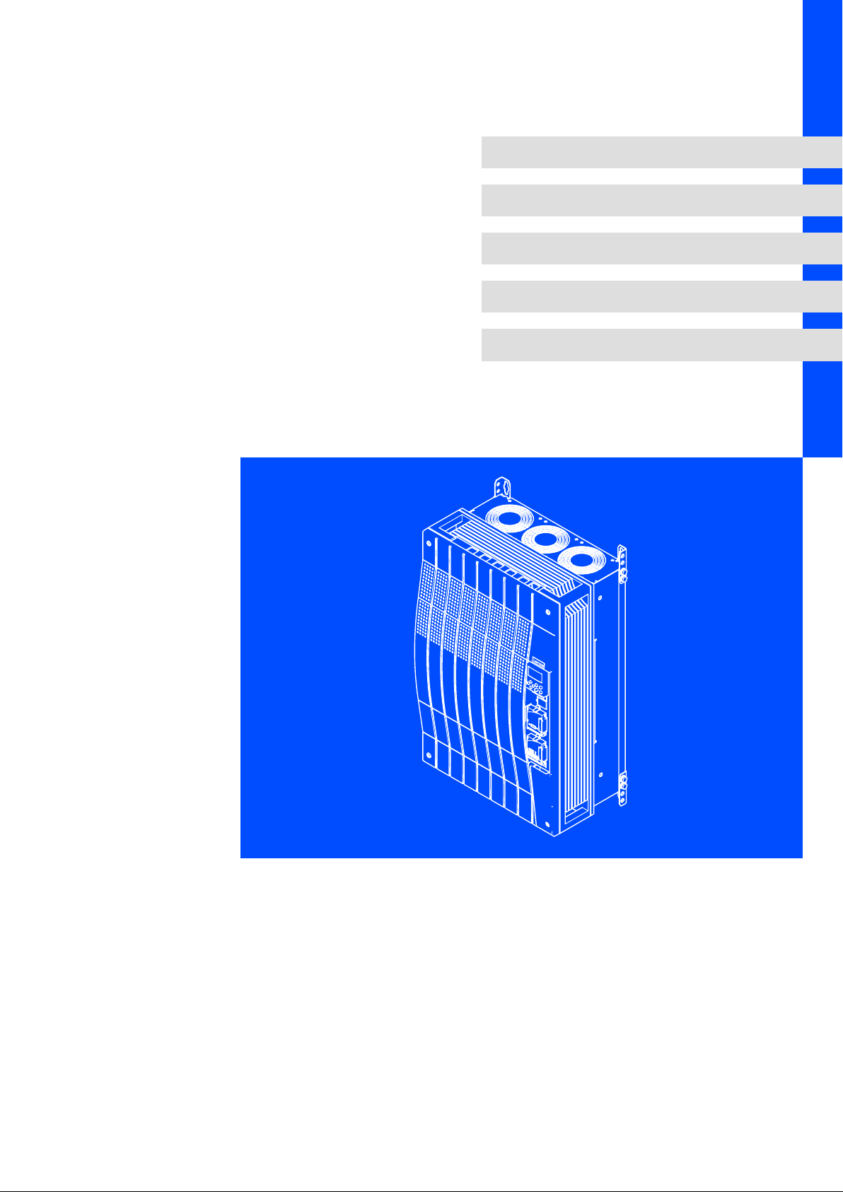
8200 vector 45 ... 90 kW
E82xV453Kxxxxx... E82xV903Kxxxxx
Frequency inverter

This documentation is valid for ...
... 8200 vector frequency inverters as of nameplate data:
Nameplate
E82 x V xxx K 4 B xxx 3x 3x
Product series
8200 vector
Type
E = Panel−mounted unit
C = Built−in unit in "cold plate" technique
D = Built−in unit in "push−through" technique
Design
V = Vector−controlled frequency inverter
Rated power [W]
453 = 45 x 103 W = 45 kW
553 = 55 x 103 W = 55 kW
753 = 75 x 103 W = 75 kW
903 = 90 x 103 W = 90 kW
9300vec112
Voltage class
4 = 400 V / 500 V
Version
Variant
0xx = EMC filter integrated
1xx = For IT systems
2xx = Without EMC filter
x0x = Without "safe standstill" function
x4x = With "safe standstill" function
xx0 = Not coated
xx1 = Coated
Hardware version
Software version

Note!
This documentation contains all the information required by the machine operator to
run the drive controllers of the 8200 vector series installed in your machine/system.
You may make further use of the information contained in this documentation without
asking Lenze for permission if you do not change the contents.
0Fig. 0Tab. 0
Tip!
Current documentation and software updates concerning Lenze products can be found
on the Internet in the "Services & Downloads" area under
http://www.Lenze.com
© 2007 Lenze Drive Systems GmbH, Hans−Lenze−Straße 1, D−31855 Aerzen
We have compiled all information in this documentation with great care und have checked it with regard to compliance with
the hardware and software described. Nevertheless, we cannot entirely exclude deviations. We do not accept legal
responsibility or liability for damage possibly resulting therefrom. We will include necessary amendments in the subsequent
editions.
E82EV453Kxxxxx, E82EV553Kxxxxx
E82EV753Kxxxxx, E82EV903Kxxxxx
8200vec311
8200vec312
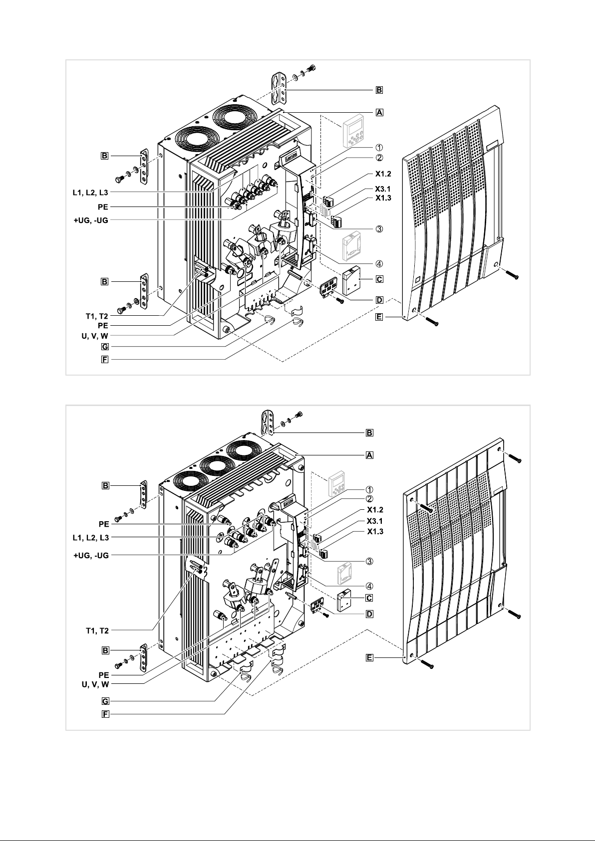
Key for overview
Position Description
Frequency inverter
Fixing bracket for standard mounting
Blind covers (2 items) for the FIF I and FIF II interfaces
EMC shield sheet with fixing screws for shielded control cables
Cover with fixing screws
Shield clamp and strain relief for the motor cable
Strain relief for the protective earth cable of the motor and the incoming cable of the motor temperature
monitoring with PTC thermistor (PTC) or thermal contact (NC contact)
T1, T2 Connection for PTC or thermal contact (NC contact) of the motor
U, V, W, PE Motor connection
L1, L2, L3, PE
, −U
+U
G
Mains connection, DC supply
G
X1.2 Terminal strip for connection of relay output K1
X1.3 Terminal strip for connection of relay output K2
X3.1 Terminal strip for connection of relay output KSR for "safe standstill" (for Bx4x variant only)
Interfaces and displays
Position Description Function
2 light−emitting diodes (red, green) Status display
AIF interface
(automation interface)
FIF I interface
(function interface)
FIF II interface
(function interface)
Slot for communication module
e. g. E82ZBC keypad
With cover for operation without function module
or slot for function module
With cover for operation without function module
or slot for function module

Contentsi
1 Safety instructions 7 . . . . . . . . . . . . . . . . . . . . . . . . . . . . . . . . . . . . . . . . . . . . . . . . . . . . . . . . .
1.1 General safety and application notes for Lenze controllers 7 . . . . . . . . . . . . . . . . . .
1.2 Residual hazards 9 . . . . . . . . . . . . . . . . . . . . . . . . . . . . . . . . . . . . . . . . . . . . . . . . . . . . .
1.3 Definition of notes used 11 . . . . . . . . . . . . . . . . . . . . . . . . . . . . . . . . . . . . . . . . . . . . . . .
2 Parameter setting 12 . . . . . . . . . . . . . . . . . . . . . . . . . . . . . . . . . . . . . . . . . . . . . . . . . . . . . . . . .
2.1 Parameter setting with E82ZBC keypad 12 . . . . . . . . . . . . . . . . . . . . . . . . . . . . . . . . . .
2.1.1 Installation and commissioning 12 . . . . . . . . . . . . . . . . . . . . . . . . . . . . . . . .
2.1.2 Display elements and function keys 13 . . . . . . . . . . . . . . . . . . . . . . . . . . . . .
2.1.3 Changing and saving parameters 15 . . . . . . . . . . . . . . . . . . . . . . . . . . . . . . .
2.1.4 Menu structure 16 . . . . . . . . . . . . . . . . . . . . . . . . . . . . . . . . . . . . . . . . . . . . . .
3 Troubleshooting and fault elimination 18 . . . . . . . . . . . . . . . . . . . . . . . . . . . . . . . . . . . . . . .
3.1 Malfunction of the drive 18 . . . . . . . . . . . . . . . . . . . . . . . . . . . . . . . . . . . . . . . . . . . . . . .
3.2 Troubleshooting 19 . . . . . . . . . . . . . . . . . . . . . . . . . . . . . . . . . . . . . . . . . . . . . . . . . . . . .
3.3 Fault messages on the keypad or in the parameter setting program
Global Drive Control 20 . . . . . . . . . . . . . . . . . . . . . . . . . . . . . . . . . . . . . . . . . . . . . . . . . .
6
EDK82EV903 EN 1.0

Safety instructions
General safety and application notes for Lenze controllers
1 Safety instructions
1.1 General safety and application notes for Lenze controllers
(in accordance with Low−Voltage Directive 2006/95/EC)
For your personal safety
Lenze controllers (frequency inverters, servo inverters, DC speed controllers) and the
accessory components can include live and rotating parts − depending on their type of
protection − during operation. Surfaces can be hot.
Non−authorised removal of the required cover, inappropriate use, incorrect installation or
operation, create the risk of severe injury to persons or damage to material assets.
More information can be obtained from the documentation.
Within the controller there are high energies. Therefore always wear personal protective
equipment when working on the live controller (body protection, headgear, eye
protection, ear protection, hand guard).
1
All operations concerning transport, installation, and commissioning as well as
maintenance must be carried out by qualified, skilled personnel (IEC 364 and CENELEC HD
384 or DIN VDE 0100 and IEC report 664 or DIN VDE 0110 and national regulations for the
prevention of accidents must be observed).
According to this basic safety information, qualified, skilled personnel are persons who are
familiar with the assembly, installation, commissioning, and operation of the product and
who have the qualifications necessary for their occupation.
Application as directed
Drive controllers are components which are designed for the installation into electrical
systems or machinery. They are not to be used as domestic appliances, but as components
only for industrial or professional purposes according to EN 61000−3−2.
When installing the controllers into machines, commissioning (i.e. starting of operation as
directed) is prohibited until it is proven that the machine complies with the regulations of
the EC Directive 98/37/EC (Machinery Directive); EN 60204 must be observed.
Commissioning (i.e. starting of operation as directed) is only allowed when there is
compliance with the EMC Directive (89/336/EEC).
The controllers meet the requirements of the Low−Voltage Directive 73/23/EEC. The
harmonised standard EN 61800−5−1 applies to the controllers.
The technical data and information on connection conditions must be obtained from the
nameplate and the documentation. They must be observed in any case.
Warning: Drive controllers are products that can be used in drive systems of category 2
according to EN 61800−3. These products can cause radio interferences in residential areas.
In this case, special measures are required.
EDK82EV903 EN 1.0
Transport, storage
Please observe the notes on transport, storage and appropriate handling.
Observe the climatic conditions according to the technical data.
7
 Loading...