

Page 1
Frequency inverter
8200 vector
0.25...90.0 kW
Lenze
Global Drive
Manual
Show/Hide Bookmarks
Page 2

bapUObsVMP
Show/Hide Bookmarks
!OQz
System Manual
8200 vector frequency inverter
0.25 kW ... 90 kW
iЙетЙ aкбоЙ pулнЙгл dгДe
mзлнС~ЕЬ NMNPRO
PNTSP e~гЙде
2002 Lenze Drive Systems GmbH
1Preface
2 Guide
3 Safety information
4 Technical data
5 Basic device installation
6 Wiring of the basic device
7 Extensions for automation
8 Commissioning
9 Parameter setting
10 Function library
11 Troubleshooting and fault elimination
12 Network of several drives
13 Braking operation
14 Reserved for chapter ”Safe standstill”
15 Application examples
16 Signal-flow charts
17 Accessories (Survey)
Page 3

Preface
Show/Hide Bookmarks
1
Contents
1 Preface
1.1 Contents
1.1 Contents 1.1-1................................................................
1.2 The 8200 vector frequency inverter 1.2-1............................................
1.3 How to use this System Manual 1.3-1...............................................
1.3.1 Information provided by the System Manual 1.3-1.............................
1.3.2 Products to which the System Manual applies 1.3-2............................
1.4 Legal regulations 1.4-1.........................................................
1.1
L
EDS 82EV903-1.0-11/2002
1.1-1
Page 4

Show/Hide Bookmarks
Page 5

Preface
Show/Hide Bookmarks
1
The 8200 vector frequency inverter
1.2 The 8200 vector frequency inverter
The system
Additional features
The mains task of 8200 vector frequency inverters is the electronic speed
adjustment of three-phase AC motors. Together with a Lenze geared motor or a
Lenzethree-phase ACmotorthe 8200vector forms anelectronic variable-speed
drive and provides excellent drive features. Different combination possibilities of
frequency inverters and application-specific modules, which can be connected
via two interfaces, ensure high flexibility.
Additional features like compact design and high functionality make the 8200
vector frequency inverter the ideal solution for almost every application, e.g. in
HVAC technology, material handling, and automation.
1.2
L
EDS 82EV903-1.0-11/2002
1.2-1
Page 6

Show/Hide Bookmarks
Page 7

Preface
Show/Hide Bookmarks
1
How to use this System Manual
Information provided by the System Manual
1.3 How to use this System Manual
1.3.1 Information provided by the System Manual
Target group
Contents
ThisSystemManualisintended forallpersonswho install,commissionand adjust
the frequency inverter 8200 vector.
Together with the catalog it forms the basis of project planning for the
manufacturers of plants and machinery.
The System Manual is meant as an addition to the Mounting Instructions which
are part of the delivery package:
l The features and functions are described in detail.
l It provides detailed information on additional ranges of application.
l Examples describe how to set the parameters for typical applications.
l In case of doubt, the Mounting Instructions delivered together with the 8200
vector frequency inverter apply.
1.3
1.3.1
How to find information
PaperorPDF
A chapter informs entirely about a subject:
l You therefore only have to read the chapter you are interested in at the
moment.
l The Table of Contents and Index help you to find all information about a
certaintopic.
l Descriptions and data of other Lenze products (drive PLC, Lenze geared
motors, Lenze motors, ...) can be found in the corresponding catalogs,
Operating Instructions and Manuals. The required documentation can be
ordered at your Lenze sales partner or downloaded as PDF file from the
internet.
TheSystem Manual is designed as a loose-leaf collection so that we are able to
inform you quickly and specifically about news and changes. Each page is
marked by publication date and version.
Simultaneously we make the System Manual available as P DFfile inthe internet.
)
) Note!
))
Current documentation and software updates for Lenze products
can be found in the internet in the area ”Downloads” under
http://www.Lenze.com
L
EDS 82EV903-1.0-11/2002
1.3-1
Page 8
1
Show/Hide Bookmarks
Preface
1.3
1.3.2
Products to which the System Manual applies
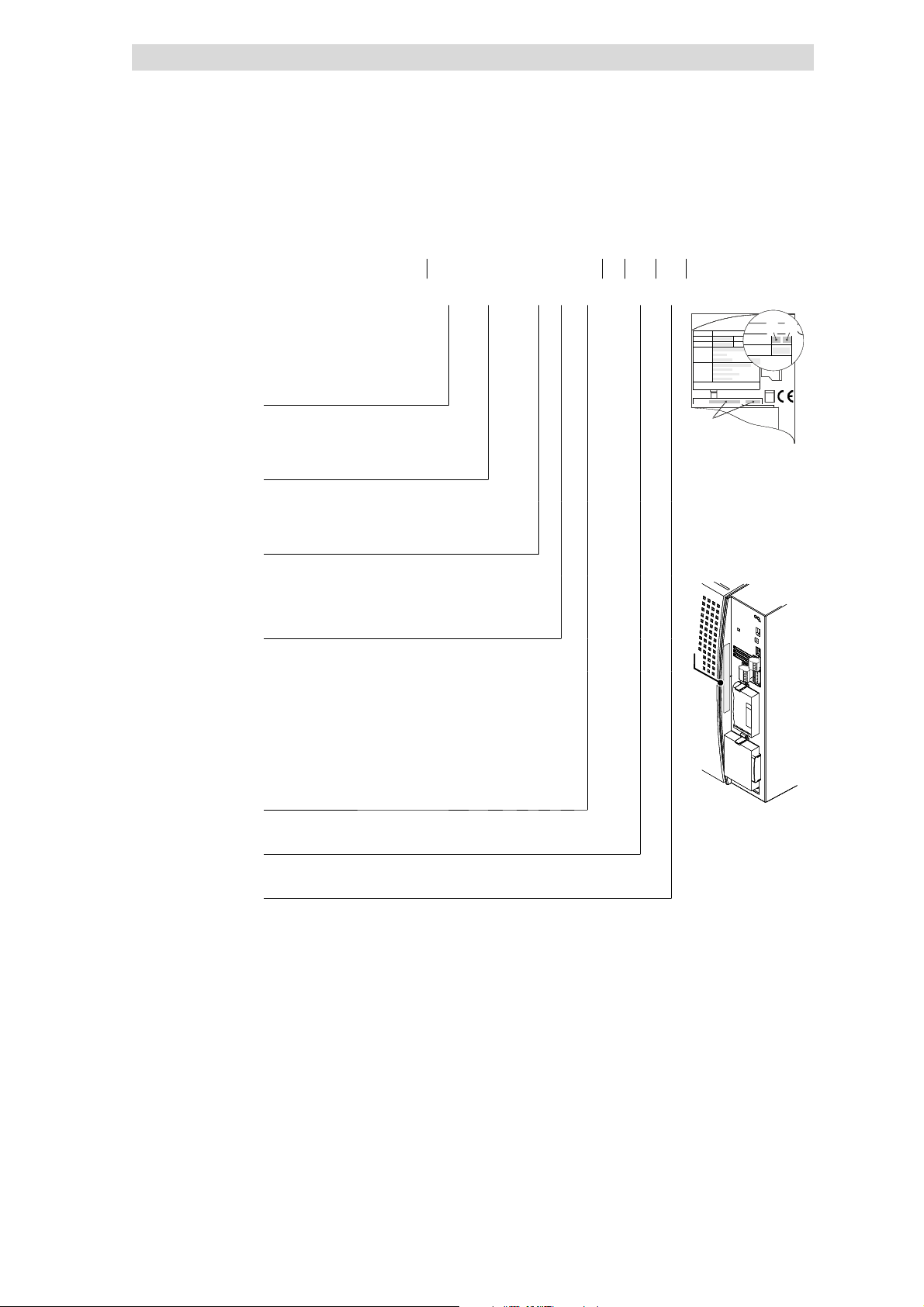
1.3.2 Products to which the System Manualapplies
E82xV xxx K x x xxx 3x 3x
Type
E = Built-in unit
D = Built-in unit in push-through
technique
C = Built-in unit in “Cold Plate”
technique
Power
(e.g.152=15
(e.g.113=11
Voltage class
2 = 230 V
4 = 400 V/500 V
× 10
× 10
2
W=1.5kW)
3
W=11kW)
How to use this System Manual
Hans-Lenze-Str.1
Hans-Lenze-Str.1
Hans-Lenze-Str.1
Hans-Lenze-Str.1
D-31855Aerzen
D-31855Aerzen
D-31855Aerzen
D-31855Aerzen
Inverter
Inverter
Inverter
Inverter
8200 vector
8200 vector
8200 vector
8200 vector
Version:
Version:
Version:
Version:
Ser.-No:
Ser.-No:
Ser.-No:
Ser.-No:
Made in Germany
Made in Germany
Made in Germany
Made in Germany
_
_
_
_
1D74
1D74
1D74
1D74
IndustrialControl
Equipment
IndustrialControl
Equipment
IndustrialControl
Equipment
IndustrialControl
Equipment
K
K
K
K
Id.-No:
Id.-No:
Id.-No:
Id.-No:
Prod.-No:
Prod.-No:
Prod.-No:
Prod.-No:
Input:
Input:
Input:
Input:
Output:
Output:
Output:
Output:
Fordetailed information refer to the manual
Fordetailed information refer to the manual
Fordetailed information refer to the manual
Fordetailed information refer to the manual
EDK82EV222
EDK82EV222
EDK82EV222
EDK82EV222
Type:
Type:
Type:
Type:
0.25 ... 11 kW
Controller generation
C (0.25 ... 11 kW)
B (15 ... 90 kW)
Version, variant
0xx = EMC filter integrated
1xx = For IT systems (15 ... 90 kW)
2xx = Without EMC filter
x0x = Without function ”Safe standstill”
x4x = With function ”Safe standstill” (3 ... 90 kW)
xx0 = Not coated
xx1 = Coated
Hardware version
Software version
E82xVxxxK4Bxxx xx xx xxE82xVxxxK4Bxxx xx xx xx
E82xVxxxK4Bxxx xx xx xx
15 ... 90 kW
1.3-2
EDS 82EV903-1.0-11/2002
L
Page 9

Preface
Show/Hide Bookmarks
1
Legal regulations
1.4 Legal regulations
Labelling
Manufacturer
CE conformity
Applicationas directed
Lenze controllers are unambiguously designated by the contents of the
nameplate.
Lenze Drive Systems GmbH, Postfach 101352, D-31763 Hameln
Conforms to the EC Low- Voltage Directive
8200 vector frequency inverters and accessories
l must only be operated under the conditions prescribed in this System
Manual.
l are components
– for open and closed loop control of variable speed drives with
– for installation into a machine
– used for assembly together with other components to form a machine.
1.4
asynchronous standard motors, reluctance motors, PM synchronous
motors with asynchronous damping cage.
l comply with the requirements of the EC Low-Voltage Directive.
l are not machines for the purposes of the EC Machinery Directive.
l are not to be used as domestic appliances, but only for industrial purposes.
Drives with 8200 vector frequency inverters
l meet the EC Electromagnetic Compatibility Directive if they are installed
according to the guidelines of CE-typical drive systems.
l canbeused
– for operation at public and non-public mains
– in industrial premises as well as residential and commercial premises.
l The user is responsible for the compliance of his application with the EC
directives.
Anyother use shall be deemed inappropriate!
L
EDS 82EV903-1.0-11/2002
1.4-1
Page 10

1
Show/Hide Bookmarks
Preface
1.4
Liability
Legal regulations
Theinformation, data, and notes inthis System Manual met thestate of theart at
the time of printing. Claims referring to drive systems which have already been
supplied cannot be derived from the information, illustrations, and descriptions
given in this Manual.
Thespecifications, processes, and circuitry described in thisSystem Manual are
for guidance only and must be adapted to your own application. Lenzedoes not
take responsibility for the suitability of the process and circuit proposals.
The specifications in this System Manual describe the product features without
guaranteeing them.
Lenzedoesnot accept any liability fordamageand operatinginterferencecaused
by:
l Diregarding this System Manual
l Unauthorized modifications to the controller
l Operating errors
l Improperworking onand withthe controller
Warranty
See Sales and Delivery Conditions of Lenze Drive Systems GmbH.
Warranty claims must be made to Lenze immediately after detecting the
deficiency or fault.
The warranty is void in all cases where liability claims cannot be made.
1.4-2
EDS 82EV903-1.0-11/2002
L
Page 11

Guide
Show/Hide Bookmarks
2
Contents
2Guide
2.1 Contents
2.1 Contents 2.1-1................................................................
2.2 Glossary 2.2-1................................................................
2.2.1 Terminology and abbreviations used 2.2-1...................................
2.2.2 Meaning of the signal names 2.2-2........................................
2.3 Total index 2.3-1..............................................................
2.4 List of illustrations 2.4-1.........................................................
2.1
L
EDS 82EV903-1.0-11/2002
2.1-1
Page 12

Show/Hide Bookmarks
Page 13

Guide
Show/Hide Bookmarks
2
Glossary
Terminology and abbreviations used
2.2 Glossary
2.2.1 Terminology and abbreviations used
AIF Automation interface
FIF Function interface
Controller Any frequency inverter, servo inverter or DC controller
Drive Lenze controller in combination with a geared motor, a
Cxxxx/y Subcode y of code Cxxxx
Xk/y Terminal y on terminal strip Xk (e. g. X3/28 = terminal 28 on
2.2
2.2.1
AIF interface, interface for communication modules
FIF interface, interface for function modules
three-phase AC motor or other Lenze drive components.
(e. g. C0410/3 = subcode 3 of code C0410)
terminal strip X3)
^ Refers to a chapter with the corresponding page number
U
[V] Mains voltage
mains
U
[V] DC supply voltage
DC
U
[V] Output voltage
M
I
[A] Mains current
mains
I
[A] Rated output current
r
I
[A] Maximum output current
max
I
[mA] Discharge current
PE
P
[kW] Rated motor power
r
P
[W] Power loss of inverter
V
P
[kW] For operation with power-adapted motors additional power t o be
DC
S
[kVA] Output power of controller
r
M
[Nm] Rated torque
r
f
[Hz] Maximum frequency
max
L[mH] Inductivity
R[Ω] Resistance
taken from the DC bus
L
AC AC current or AC voltage
DC DC current or DC voltage
DIN Deutsches Institut für Normung
EMC Electromagnetic compatibility
EN European standard
EDS 82EV903-1.0-11/2002
2.2-1
Page 14

2
Show/Hide Bookmarks
Guide
2.2
2.2.2
IEC
IP International Protection Code
NEMA National Electrical Manufacturers Association
VDE Verband deutscher Elektrotechniker
CE Communauté Européene
UL Underwriters Laboratories
2.2.2 M eaning of the signalnames
AIF-IN Automation interface input
AIF-OUT Automation interface output
AIN1 Analog input 1
Glossary
Meaning of the signal names
International Electrotechnical Commission
Function block AIF input
Function block AIF output
Function block analog input 1
AIN1-GAIN Analog input 1 gain
AIN1-OFFSET Analog input 1 offset
AIN1-OUT Analog input 1 output
AIN2 Analog input 2
AIN2-GAIN Analog input 2 gain
AIN2-OFFSET Analog input 2 offset
AIN2-OUT Analog input 2 output
AOUT1 Analog output 1
AOUT1-GAIN Analog output 1 gain
AOUT1-IN Analog output 1 in
AOUT1-OFFSET Analog output 1 offset
Gain of analog input 1
Offset of analog input 1
Output of analog input 1
Function block analog input 2
Gain of analog input 2
Offset of analog input 2
Output of analog input 2
Function block analog output 1
Gain of analog output 1
Input of analog output 1
Offset of analog output 1
2.2-2
AOUT1-OUT Analog output 1 out
Output of analog output 1
AOUT2 Analog output 2
Function block analog output 2
AOUT2-GAIN Analog output 2 gain
Gain of analog output 2
EDS 82EV903-1.0-11/2002
L
Page 15

Guide
Show/Hide Bookmarks
2
Glossary
Meaning of the signal names
AOUT2-IN
AOUT2-OFFSET Analog output 2 offset
AOUT2-OUT Analog output 2 out
DCTRL1 Digital control 1
DCTRL1-C0010...C0011 DCTRL1-output speed between C0010 and C0011
DCTRL1-CCW DCTRL1-counter-clockwise
DCTRL1-CCW/QSP DCTRL1-counter-clockwise/quickstop
DCTRL1-CINH DCTRL1-controller inhibit
Analog output 2 in
Input of analog output 2
Offset of analog output 2
Output of analog output 2
Function block device control
Status signal:
Output frequency within the set limits of C0010 and C0011
Status signal:
CCW rotation
Activates CCW rotation with quickstop
Controller inhibit
or status signal:
Controller inhibited
2.2
2.2.2
DCTRL1-CW/CCW DCTRL1-clockwise/counter-clockwise
DCTRL1-CW/QSP DCTRL1-clockwise/quickstop
DCTRL1-H/RE DCTRL1-hand/remote
DCTRL1-IMOT<ILIM DCTRL1-motor current < current limit
DCTRL1-(IMOT<ILIM)-QM IN DCTRL1-motor curren t < current limit and Qmin active
DCTRL1-(IMOT< ILIM)-RFG-I= O DCTRL1-motor current < current limit and RFG in=out
DCTRL1-(IMOT> ILIM)-RFG-I= O DCTRL1-motor current > current limit and RFG in=out
DCTRL1-IMP DCTRL1-pulse inhibit
CW/CCW rotation changeover
Activates CW rotation with quickstop
Hand control/remote control changeover
Status signal:
Apparent motor current < current threshold
Status signal:
Apparent motor current < values remain under current threshold
and frequency threshold Qmin
Status signal:
Apparent motor current < current threshold and ramp-function
generator = ramp-function generator output
Status signal:
Apparent motor current > current threshold and ramp function
generator input = ramp function generator output
Status signal:
Pulse inhibit
L
DCTRL1-LP1-WARN DCTRL1-lost phase 1 warning
Warning signal:
Motor phase failure
EDS 82EV903-1.0-11/2002
2.2-3
Page 16

2
Show/Hide Bookmarks
Guide
2.2
2.2.2
Glossary
Meaning of the signal names
DCTRL1-NOUT=0
DCTRL1-OH-WARN DCTRL1-overheat warning
DCTRL1-OH-PTC-LP1-FAN1-WARN DCTRL1-warning: overheat or motor temperature or lost
DCTRL1-OV DCTRL1-overvoltage
DCTRL1-PAR-B0 DCTRL1-parameter set 2 or 4 active
DCTRL1-PAR-B1 DCTRL1-parameter set 3 or 4 active
DCTRL1-speed output = 0
Status signal:
Output frequency = 0 Hz
Warning signal:
Overtemperature
phase or fan failure
Warning signal:
Overtemperature or motor temperature too high or motor phase
or fan have failed
Warning signal:
DC bus overvoltage
Status signal:
Parameterset2or4active
Status signal:
Parameterset3or4active
DCTRL1-PAR2/4 DCTRL1-activation of parameter set 2 or 4
DCTRL1-PAR3/4 DCTRL1-activation of parameter set 3 or 4
DCTRL1-PTC-WARN DCTRL1-motor temperature warning
DCTRL1-QSP DCTRL1-activation of quickstop
DCTRL1-RDY DCTRL1 ready
DCTRL1-RFG1=NOUT DCTRL1-RFG1 = speed output
DCTRL1-RUN DCTRL1-motor is running
DCTRL1-RUN-CCW DCTRL1-motor runs counter-clockwise
DCTRL1-RUN-CW DCTRL1-motor runs clockwise
Activates parameter set 2 or 4
Activates parameter set 3 or 4
Warning signal:
Motor temperature too high
Activates quickstop
Status signal:
Ready for operation
Status signal:
Frequency setpoint has been reached
Status signal:
Motor runs
Status signal:
Motor runs/CCW rotation
Status signal:
Motor runs/CW rotation
2.2-4
DCTRL1-TRIP DCTRL1-TRIP active
Status signal:
Fault message (TRIP) active
DCTRL1-TRIP-QMI N-IMP DCTRL1-TRIPorQminorIMPactive
Status signal:
TRIP or Qmin have not been reached or pulse inhibit active
EDS 82EV903-1.0-11/2002
L
Page 17

Guide
Show/Hide Bookmarks
2
Glossary
Meaning of the signal names
DCTRL1-TRIP-RESET
DCTRL1-TRIP-SET DCTRL1-external TRIP active
DFIN1 Digital frequency input 1
DFIN1-GAIN Digital frequency input 1 gain
DFIN1-NORM Digital frequency input 1 normalisation
DFIN1-OFFSET Digital frequency input 1 offset
DFIN1-ON Digital frequency input 1 on
DFIN1-OUT Digital frequency input 1 output
DCTRL1-TRIP-reset
Fault message reset
Evaluation of external fault messages
Function block frequency input 1
Gain of frequency input 1
Normalisation of frequency input 1
Offset of frequency input 1
Activation of frequency input 1
Output of frequency input 1
2.2
2.2.2
DFOUT1 Digital frequency output 1
DFOUT1-AN-IN Analog input of digital frequency output 1
DFOUT1-OUT Digital frequency output 1 output
DIGIN1 Digital Input 1
DIGOUT1 Digital output 1
DIGOUT2 Digital output 2
FIXED-FREE Input or output not connected
MCTRL1 Motor controL 1
MCTRL1-DCB MCTRL1-activation of direct current brake
MCTRL1-DCVOLT MCTRL1-DC voltage
MCTRL1-Imax MCTRL1-Imax
Function block frequency input 1
Analog input of frequency output 1
Output of frequency output 1
Function block digital inputs 1
Function block digital output 1
Function block digital output 2
Input or output not assigned
Function block motor control 1
Activates DC braking
DC bus voltage
Status signal:
Maximum current of controller is reached or torque setpoint is
reached
L
MCTRL1-IMOT MCTRL1-motor current
Apparent motor current
MCTRL1-MOUT MCTRL1-torque output
Torque delivered (utilisation)
EDS 82EV903-1.0-11/2002
2.2-5
Page 18

2
Show/Hide Bookmarks
Guide
2.2
2.2.2
Meaning of the signal names
MCTRL1-MSET
MCTRL1-MSET1 MCTRL1-torque setting 1
MCTRL1-MSET1=MACT MCTRL1-torque setting 1= actual torque
MCTRL1-MSET2 MCTRL1-torque setting 2
MCTRL1-MSET2=MACT MCTRL1-torque setting 2= actual torque
MCTRL1-NOUT MCTRL1-speed output
MCTRL1-(1/NOUT) MCTRL1-(1/speed output)
MCTRL1-NOUT+SLIP MCTRL1-speed output + slip
MCTRL1-torque setpoint
Torque setpoint or torque limiting value
Torque threshold 1
Torque threshold 1 is reached
Torque threshold 2
Torque threshold 2 is reached
Output frequency
Output signal 1/C0050
Output frequency with slip compensation
Glossary
MCTRL1-PHI-ADD MCTRL1-additional phase
MCTRL1-VOLT MCTRL1-voltage
MCTRL1-VOLT-ADD MCTRL1-additional voltag e
MPOT1 Motor potentiometer 1
MPOT1-DOWN MPOT1-down
MPOT1-INIT MPOT1-initialisation
MPOT1-QSP MPOT1-quickstop
MPOT1-OUT MPOT1-output
MPOT1-UP MPOT1-up
NSET1 Speed setting 1
Additional phase
Motor voltage
Additional motor voltage
Motor potentiometer 1
Setpoint is driven to minimum output frequency at main setpoint
deceleration ramp
Configuration motor potentiometer
Activation of quickstop via motor potentiometer
Motor potentiometer output
Setpoint is driven to maximum output frequency at main
setpoint acceleration ramp
Function block speed setting
2.2-6
NSET1-JOG1/3 NSET1-activation of fixed setpoint 1 or 3
Activates fixed setpoint (JOG) 1 or 3
NSET1-JOG1/3/5/7 NSET1-activation of fixed setpoint 1, 3, 5 or 7
Activates fixed setpoint (JOG) 1, 3, 5 or 7
NSET1-JOG2/3 NSET1-activation of fixed frequency 2 or 3
Activates fixed setpoint (JOG) 2 or 3
EDS 82EV903-1.0-11/2002
L
Page 19

Guide
Show/Hide Bookmarks
2
Glossary
Meaning of the signal names
NSET1-JOG2/3/6/7
NSET1-JOG4/5/6/7 NSET1-activation of fixed frequency 4, 5, 6 or 7
NSET1-N1 NSET1-speed setpoint 1
NSET1-N2 NSET1-speed setpoint 2
NSET1-NADD NSET1-additional s peed setpoint
NSET1-NOUT NSET1-speed output
NSET1-RFG1 NSET1-ramp function generator 1
NSET1-RFG1-0 NSET1-ramp function generator 1 = 0
NSET1-activation of fixed frequency 2, 3, 6 or 7
Activates fixed setpoint (JOG) 2, 3, 6 or 7
Activates fixed setpoint (JOG) 2, 3, 6 or 7
Main setpoint 1
Main setpoint 2
Additional setpoint via keypad or parameter channel (C0140)
Output of ramp function generator 1
Ramp function generator 1 for main setpoint
Ramp function generator input must be set to ”0” for mains
setpoint
2.2
2.2.2
NSET1-RFG1-I=O NSET1-ramp function generator 1 input=output
NSET1-RFG1-IN NSET1-ramp function generator 1 input
NSET1-RFG1-STOP NSET1-ramp function generator 1 stop
NSET1-TI1/3 NSET1-activation of timer 1 or 3
NSET1-TI2/3 NSET1-activation of timer 2 or 3
PCTRL1 Process control 1
PCTRL1-INV-ON PCTRL1-inversion on
PCTRL1-ACT PCTRL1-actual value
PCTRL1-FADING PCTRL1-fading
PCTRL1-FOLL1 PCTRL1-follow1
PCTRL1-FOLL-OUT PCTRL1-follow1 output
Status signal:
Ramp function generator, input = output
Signal at ramp function generator input
Stop of ramp function generator for main setpoint
Activates additional acceleration time/deceleration time 1 or 3
Activates additional acceleration time/deceleration time 2 or 3
Function block process controller 1
Process controller output inversion
Actual process controller value
Fading in or fading out process controller output
Servo controller 1
Servo controller output
L
PCTRL1-FOLL1-0 PCTRL1-follow1 = 0
Setting of servo controller to ”0”
PCTRL1-I-OFF PCTRL1-integration off
Switches off I-component of the process controller
EDS 82EV903-1.0-11/2002
2.2-7
Page 20

2
Show/Hide Bookmarks
Guide
2.2
2.2.2
Meaning of the signal names
PCTRL1-LIM
PCTRL1-NADD PCTRL1-additional speed setpoint
PCTRL1-NADD-OFF PCTRL1- additional speed setpoint off
PCTRL1-NMIN PCTRL1-speed minimum
PCTRL1-NOUT PCTRL1-speed output
PCTRL1-OFF PCTRL1-off
PCTRL1-OUT PCTRL1-output
PCTRL1-limit
Status signal:
Limitation of process controller output is reached
Additional setpoint
Additional setpoint is switched off
Status signal:
Minimum output frequency is reached
Total setpoint = main setpoint, additional setpoint and process
controller setpoint with pilot control
Process controller switch off
Process controller output without pilot control
Glossary
PCTRL1-PID-OUT PCTRL1-PID controller output
PCTRL1-QMIN PCTRL1-Qmin
PCTRL1-RFG1 PCTRL1-ramp function generator1
PCTRL1-RFG2 PCTRL1-ramp function generator2
PCTRL1-RFG2-LOAD-I PCTRL1-load actual value to ramp function generator2
PCTRL1-RFG2-0 PCTRL1- ramp function generator2 = 0
PCTRL1-SET PCTRL1-setpoint
PCTRL1-SET=ACT PCTRL1-setpoint = actual value
PCTRL1-SET1 PCTRL1-setpoint 1
Output signal PID controller
Status signal:
Frequency threshold Qmin is not reached
Process controller of ramp function generator 1 for additional
setpoint PCTRL1-NADD
Process controller of ramp function generator 2 for process
controller setpoint
Loads the actual process controller value to the ramp function
generator of the process controller
Ramp function generator input is set to ”0”
Output signal of process controller setpoint
Status signal:
Process controller setpoint = actual process controller value
Process controller setpoint 1
2.2-8
PCTRL1-SET2 PCTRL1-setpoint 2
Process controller setpoint 2
PCTRL1-SET3 PCTRL1-setpoint 3
Total setpoint = main setpoint and additional setpoint without
process controller setpoint and without pilot control
PCTRL1-STOP PCTRL1-stop
Process controller stop
EDS 82EV903-1.0-11/2002
L
Page 21

Guide
Show/Hide Bookmarks
2
Glossary
Meaning of the signal names
RELAY1
RELAY2 Relay 2
RFG Ramp function generator
Relay 1
Relay 1
Relay 2
Ramp function generator
2.2
2.2.2
L
EDS 82EV903-1.0-11/2002
2.2-9
Page 22

Show/Hide Bookmarks
Page 23

Guide
Show/Hide Bookmarks
2
Total index
2.3 Total index
230 V controller, Mains connection, 6.4-4
400 V controller, Mains connection, 6.4-5, 6.6-4,
6.7-4, 6.8-4
87 Hz technology, 10.3-6
A
AC motor braking, 10.7-8
Acceleration, 10.7-1
Acceleration time
- Additional setpoint , 10.7-1, 10.20-20
- Minimum frequency limitation, 10.6-1, 10.20-21
- Process controller setpoint, 10.20-20
Acceleration times, 10.7-1
Accessories, 17.1-1
- External brake resistor, 13.4-1
- General, 17.2-1
- T ype-specific, 17.3-1
Actual value, Digital supply, 10.8-9
Actualvalue selection, 10.8-1
- PID controller, 10.10-6
Adjustment
- Bipolar setpoint, 10.8-6
- Inverse setpoint, 10.8-7
- Unipolar setpoint, 10.8-6
Analog input 1
- Gain, 10.8-3, 10.20-9
- Offset, 10.8-3, 10.20-9
Analog input signals, 10.12-1
Analog inputs
- Automatic adjustment, 10.8-4, 10.20-43
- Gain, 10.8-3, 10.20-30
- Offset, 10.8-3, 10.20-30
Analog output 1
- Gain, 10.12-7, 10.20-12
- Offset, 10.12-7, 10.20-12
2.3
Analog output signals, 10.12-4
Analog outputs, Configuration, 10.12-4
Analog process data output words, Configuration,
10.12-10
Application, as directed, 1.4-1
Applicationas directed, 1.4-1
Application conditions, 9.3-1, 9.4-1
Applicationdatum,Display, 10.16-1
Application examples, 15.1-1
Application I/O
- Acceleration times main setpoint, 10.7-1, 10.20-12
- Additional JOG values, 10.8-13, 10.20-43
- Automatic analog input adjustment, 10.8-4, 10.20-43
- Automatic frequency input adjustment , 10.8-10,
10.20-43
- Calibration of process variable, 10.16-3, 10.20-44
- Deceleration times main setpoint, 10.7-1, 10.20-12
- Delay digital outputs, 10.13-9, 10.20-41
- Main and additional setpoint, 10.20-19
- Offset analog outputs, 10.12-8, 10.20-41
- Output signal range - analog outputs, 10.12-8,
10.20-42
- Setpoint selection range, 8.6-5, 10.8-3, 10.20-9
- T erminal assignment, 7.2-9, 7.3-9, 7.4-9
Applicationexamples
- Dancer position control, 15.4-1
- Group drive, 15.6-1
- Operation of medium-frequency motors, 15.3-1
- Power control, 15.9-1
- Pressure control, 15.2-1
- Sequential circuit, 15.7-1
- Setpoint summation, 15.8-1
- Speed control, 15.5-1
Approvals, 4.2-1
Asynchronous standard motors, 1.4-1
Auto-TRIP reset, 11.5-1
L
EDS 82EV903-1.0-11/2002
2.3-1
Page 24

2
Show/Hide Bookmarks
Guide
2.3
B
Bargraph display, Keypad E82ZBC, 9.3-3
Basic device, Installation, 5.1-1
Basic device installation, 5.1-1
Basic settings, Own, 8.6-2, 10.17-2, 10.20-4
Basic unit, Wiring, 6.1-1
Baud rate, 10.20-14
Bipolar setpoint, Adjustment, 10.8-6
Brake
- Switching, 13.3-1
- Wiring, 13.3-2
Brake rectifier, 13.3-1
Brake resistor, 13.4-9
- Selection, 13.4-8
- Wiring, 13.4-10
Brake transistor, 13.4-1
- Threshold, 10.20-18, 13.4-1
Braking, 10.7-1, 13.1-1
Braking operation, 13.1-1
- Brake rectifier, 13.3-1
- Brake wiring, 13.3-2
- Controlling the brake via the relay output, 13.3-2
- in a drivesystem, 12.8-1
- Switching the brake, 13.3-1
- With external brake resistor, 13.4-1
- With three-phase AC brake motors, 13.3-1
- without additional measures, 13.2-1
Bus systems, Setpoint selection, 10.8-16
Total index
C
Cable cross-section,Network of several drives,
12.4-6
Cable cross-sections
- DC bus, 12.4-4
- Operation at rated power
230 V , 4.3-4
400 V , 4.3-9
500 V , 4.3-14
- Operation with increased rated power
230 V , 4.4-3
400 V , 4.4-8
Cable specifications, 6.2-5
Calibration, Application datum, 10.16-1
Calling up a password-protected function, E82ZBC
keypad, 9.3-9
CAN bus identifier, 10.19-2, 10.20-24
CAN bus node address, 10.19-1, 10.20-24
CE conformity, 1.4-1
Central supply.
Change and save parameters, EMZ9371BC keypad,
9.4-5
Changeover, Setpoints, 10.8-17
Changing and savingparameters, w ith E82ZBC
keypad, 9.3-5
Check, before commissioning, 8.2-1
Chopper frequency of inverter, 10.4-3
- noise optimised, 10.4-3
Chopper frequency reduction, 10.4-4
Code, 9.2-1
Code table, Explanation of, 10.20-1
Code table for controllers, 10.20-1
”Cold plate”, Requirements on the cooler, 5.3-6,
5.4-4, 5.5-5
Commissioning, 8.1-1
- Check before, 8.2-1
Communication error, Reactiont o, 10.20-14
Compensation equipment, Interactions with, 6.2-4
Siehe DC-bus connection
2.3-2
EDS 82EV903-1.0-11/2002
L
Page 25

Guide
Show/Hide Bookmarks
2
Total index
Configuration
- Acceleration times and deceleration times, 10.7-1
- Actual value selection, 10.8-1
- Analog input signals, 10.12-1
- Analog output signals, 10.12-4
- Analog outputs, 10.12-4
- Analog process data output words, 10.12-10
- Change of direction of rotation, 10.7-5
- Chopper frequency of inverter, 10.4-3
- Code table, 10.20-1
- Communication monitoring, 10.20-14
- Controller inhibit (DCTRL1-CINH), 10.5-3
- Current limits, 10.6-3
- Current-limit controller, 10.11-1
- DC-injection brake (DCB), 10.7-6
- Digital input signals, 10.13-1
- Digital output signals, 10.13-6
- Digital outputs, 10.13-6
- Display functions, 10.16-1
- Function library, 10.1-1
- Manual / remote operation, 10.8-17
- Maximum field frequency, 10.6-1
- Minimum field frequency, 10.6-1
- Monitoringfunctions
external faults, 10.15-1
Motor temperature, 10.14-1
- Motor data detection, 10.9-1
- Oscillation damping, 10.4-4
- Parameter set changeover, 10.17-5
- Process data output words, 10.13-12
- Quick stop (QSP), 10.7-4
- Relay output, 10.13-6
- Setpoint selection, 10.8-1
- Setpoint source selection, 10.8-1
- Slip compensation, 10.4-1
- Speed limit values, 10.6-1
- Start conditions/flying-restart circuit, 10.5-1
- Thermal motor monitoring, 10.14-1
- TRIP reset, 10.15-1
- TRIP set, 10.15-1
- V/f rated frequency, 10.3-5
- Vmin boost, 10.3-7
Conformity, 1.4-1, 4.2-1
Control characteristics, Process controller, 10.10-1
Control connections
- T erminal assignment - application I/O, 7.2-9, 7.3-9,
7.4-9
- T erminal assignment - standard I/O, 7.2-4, 7.3-4,
7.4-4
- T erminal assignment - standard I/O PT, 7.2-8, 7.2-13,
7.3-8, 7.3-13, 7.4-8, 7.4-13
Control word, 10.20-15
Controlleddeceleration after mainsfailure, 10.5-4
2.3
Controller
- Application as directed, 1.4-1
- Labelling, 1.4-1
Controller inhibit, Drive performance, 10.5-1, 10.5-3
Controller protection, 3.4-1
Controlling the brake
- Parameter setting of the relay output, 13.3-2
- Via the relay output, 13.3-2
Copyingparameter sets
- E82ZBC keypad, 9.3-6
- XT EMZ9371BC keypad, 9.4-6
Copying parameters, to other controllers
- E82ZBC keypad, 9.3-6
- XT EMZ9371BC keypad, 9.4-6
Current limits, 10.6-3
Current-limit controller, 10.11-1
D
Dancer position control, 15.4-1
Data, Keypad E82ZBC, 9.3-1
DC bus, Cable cross-section, 12.4-4
DC groupdrives, 4.2-1
DC-bus connection
- Braking in, 12.8-1
- Central supply, 12.6-1
- Central supply via external D Csource, 12.6-1
- Central supply via regenerative power supply module,
12.6-2
- DC-bus connection, 12.4-4
- Decentralised supply, 12.7-1
- Decentralised supply with single-phase or two-phase
mains connection, 12.7-1
- Decentralised supply with three-phase mains
connection, 12.7-2
- Mains connection, 12.4-2
- Possible combinations, 12.4-1
- Protection concept, 12.4-8
- Required mains filters/mains chokes, 12.5-2
DC-bus fuse, 12.4-5
DC-injection brake, 10.7-6
Dead band
- Settings with auto DCB, 10.7-8
- With analog setpoint selection, 10.8-5
Debouncing
- Digital output signal ”Torque threshold reached”,
10.20-22
- Digital output signal PCTRL1-LIM, 10.20-20
- Digital output signal PCTRL1-SET=ACT, 10.20-20
- Digital outputs, 10.13-9, 10.20-41
Deceleration, 10.7-1
L
EDS 82EV903-1.0-11/2002
2.3-3
Page 26

2
Show/Hide Bookmarks
Guide
2.3
Deceleration t ime
- Additional setpoint, 10.7-1, 10.20-20
- Process controller setpoint, 10.20-20
Deceleration t imes, 10.7-1
Decentralised supply.
Default setting
- load, 8.6-1, 10.17-1, 10.20-3
- Restorage, 8.6-1, 10.17-1, 10.20-3
Definitions
- Signal names, 2.2-2
-Terms,2.2-1
Degree of pollution, 4.2-1
Delay digital outputs, Application I/O, 10.13-9,
10.20-41
Derating, 10.4-3, 10.4-4, 10.6-3
Diagnostics, 10.16-1, 10.16-4, 10.20-19
Digital input signals, 10.13-1
Digital inputs, Level inversion, 10.13-5, 10.20-14,
10.20-29
Digital output signals, 10.13-6
Digital outputs
- Configuration, 10.13-6
- Level inversion, 10.13-9, 10.20-34
Direction of rotation
- Failsafechange, 10.7-5
- Nonfail-safe change, 10.7-5
Display
- Application datum, 10.16-1
- Operating status, 11.2-1
- Software version, 10.16-4, 10.20-11
- T ype, 10.16-4, 10.20-11
Display functions, 10.16-1
- Possible values, 10.16-1
Display of operating data, 10.16-1
Display values, 10.16-1
- Calibration, 10.16-1
Displays, Keypad E82ZBC, 9.3-3
Disposal, 3.2-3
Drive performance
- at mains disconnection, 10.5-1
- at mains failure, 10.5-1
- Controller inhibit, 10.5-3
- Controller inhibit/controller release, 10.5-1
- in case of errors, 11.3-1
Dry running protection, 10.6-1, 15.2-1
Siehe DC-bus connection
Total index
E
e.l.c.bs, 6.2-4
- Operation with, 6.2-4
E82ZBC keypad, 8.4-1, 9.3-1
- Bargraph display, 9.3-3
- Calling up a password-protected function, 9.3-9
- Cancel password protection, 9.3-9
- Changing and saving parameters, 9.3-5
- Copying parameter sets, 9.3-6
- Functionkeys, 9.3-4
- Password protection, 9.3-8
- Remote parameter setting, 9.3-10
- Status d isplay, 9.3-3
Earthfault,Detection, 10.14-3
Earth fault detection, 10.14-3
Electrical installation, 6.1-1
- Power connections, 6.6-4, 6.7-4, 6.8-4
- Relay output connection, 6.4-7, 6.5-7
EMC, 4.2-2
Emergency off
- Controlled deceleration with, 10.5-4
- Controller inhibit, 10.5-3
EMZ9371BC keypad, Change and save parameters,
9.4-5
EN 61000-3-2, 4.2-2, 6.2-3
Enclosure, 4.2-2
Error analysis, 11.2-1
Error elimination, 11.4-1
Error message, Reset, 11.5-1
Error messages, 11.4-1
Errors,external fault evaluation, 10.15-1
F
Fault elimination, 11.1-1
Fault message, External, 10.15-1
Fault message reset, , 10.15-1
Field frequency
- maximum, 10.6-1
- Minimum, 10.6-1
Fixed setpoint (JOG), 10.8-13
Flying-restart circuit, 3.4-1, 10.5-1
Frequency, Skipping, 10.4-6
Frequency input
- Automatic adjustment, 10.8-10, 10.20-43
- digital, 10.8-9
Frequency precontrol, 10.10-5
Frequencysetpoint reached, Switchingwindow,
10.20-19
2.3-4
EDS 82EV903-1.0-11/2002
L
Page 27

Guide
Show/Hide Bookmarks
2
Total index
Function keys, E82ZBC keypad, 9.3-4
Function library, 10.1-1
- Important notes, 10.2-1
Fuses
- Network ofseveraldrives, 12.4-6
- Operation at rated power
230 V , 4.3-4
230 V (UL), 4.3-4, 4.4-3
400 V , 4.3-9
400 V (UL), 4.3-9
500 V , 4.3-14
500V (UL), 4.3-14
- Operation with increased rated power
230 V , 4.4-3
400 V , 4.4-8
400 V (UL), 4.4-8
G
Gain
- Analog input 1, 10.8-3, 10.20-9
- Analog inputs, 10.8-3, 10.20-30
- Analog output 1, 10.12-7, 10.20-12
- Imax controller, 10.3-11, 10.11-1, 10.20-11
Generalaccessories, 17.2-1
General data, 4.2-1, 9.3-1, 9.4-1
Group drive, 15.6-1
Guide, 2.1-1
H
Harmonic currents,Limitation according t o EN
61000-3-2, 4.2-2
2.3
Installation
- electrical, 6.1-1
- Keypad E82ZBC, 9.3-2
- mechanical, 5.1-1, 7.2-1, 7.3-1, 7.4-1
,5.3-6,5.5-5
”Cold plate” technique, 5.3-6, 5.4-4, 5.5-5
”Cold plate”technique 3... 11kW, 5.4-4
DIN rail mounting 0.25 ... 2.2 kW, 5.3-8
Lateral mounting 0.25 ... 2.2 kW, 5.3-9
Lateral mounting 3 ... 11 kW, 5.4-6, 5.4-7
Mounting with fixing rails 0.25 ... 2.2 kW, 5.3-1
Mounting with fixing rails 3 ... 11 kW, 5.4-1
Thermally separated mounting (push-through
technique) 0.25 ... 0.75 kW, 5.3-2
Thermally separated mounting (push-through
technique) 1,5 ... 2,2 kW, 5.3-4
Thermally separated mounting (push-through
technique) 15 ... 30 kW, 5.5-4
Thermally separated mounting (push-through
technique) 3 ... 11 kW, 5.4-2
Thermally separated mounting (push-through
technique) 45 ... 55 kW, 5.6-4
Thermally separated mounting (push-through
technique) 75 ... 90 kW, 5.7-5
with built-on mains filter 15... 30 kW, 5.5-3
with built-on mains filter 45... 55 kW, 5.6-3
with built-on mains filter 75... 90 kW, 5.7-3, 5.7-4
with fixing bracket 15 ... 30 kW, 5.5-1
with fixing bracket 45 ... 55 kW, 5.6-1
with fixing brackets 75 ... 90 kW, 5.7-1
with footprint mains filter 15 ... 30 kW, 5.5-2
with substructure mains filter 45 ... 55 kW, 5.6-2
with substructure mains filter 75 ... 90 kW, 5.7-2
Installation height, 4.2-1
Insulation of circuits, 4.2-2
Insulation resistance, 4.2-2
Integral action time, Imax controller, 10.3-11,
10.11-1, 10.20-11
Interactions with compensation equipment, 6.2-4
Inverse setpoint, Adjustment, 10.8-7
Hide time, Process controller, 10.20-20
History buffer, 11.2-1
- Assembly, 11.2-1
Humidity class, 4.2-1
I
I2xt monitoring, 10.14-1
Imax controller
- Gain, 10.3-11, 10.11-1, 10.20-11
- Integral action time, 10.3-11, 10.11-1, 10.20-11
Input signals
- Analog, Configuration, 10.12-1
- digital, Configuration, 10.13-1
Inputs
- digital, Response times, 10.13-1
- PTC, 10.14-3
L
J
JOG ( fixed setpoint), 10.8-13
JOG frequencies, Additional, 10.8-13, 10.20-43
Jumper, Analog signal selection, 10.8-3
K
Keypad, Setpoint selection, 10.8-15
Keypad E82ZBC
- data, 9.3-1
- Activation of password protection, 9.3-8
- Installation, 9.3-2
- Menu structure, 9.3-11
Keypad EMZ9371BC, Remote parameter setting,
9.4-9
Keypad XT EMZ9371BC
- Activation of password protection, 9.4-8
- Password protection, 9.4-8
EDS 82EV903-1.0-11/2002
2.3-5
Page 28

2
Show/Hide Bookmarks
Guide
2.3
L
Labelling, Controller, 1.4-1
Layout of safety notes, 3.5-1
LED display, 11.2-1
LED’s, 11.2-1
Legal regulations, 1.4-1
Level inversion
- Digital inputs, 10.13-5, 10.20-14, 10.20-29
- Digital outputs, 10.13-9, 10.20-34
Liability, 1.4-2
Limit value, 10.6-1
- Setting, 10.6-1
List of illustrations, 2.4-1
M
Main and additional setpoint, Application I/O,
10.20-19
Mains conditions, 6.2-2
Mains connection
- 230/240 V, 6.4-4
- 400/500 V, 6.4-5, 6.6-4, 6.7-4, 6.8-4
Mains disconnection, Drive performance, 10.5-1
Mains failure, Drive performance, 10.5-1
Mains filters/mains chokes, for DC-bus connection,
12.5-2
Mains types, 6.2-2
- permissible, 4.2-2
Mains voltage compensation, 10.3-5
Maloperation of the drive, 11.4-1
Manual / remote operation, 10.8-17
Manufacturer, 1.4-1
Max. limit process controller output, 10.20-20
Maximum motor cable length, 6.2-5
Total index
Mechanical installation, 5.1-1, 7.2-1, 7.3-1, 7.4-1
- ”Cold plate” technique, 5.3-6, 5.4-4, 5.5-5
Requirements on the cooler, 5.3-6, 5.4-4, 5.5-5
- ”Cold plate”technique 3 ... 11 kW, 5.4-4
- DIN rail mounting 0.25 ... 2.2 kW, 5.3-8
- Lateral mounting 0.25 ... 2.2 kW , 5.3-9
- Lateral mounting 3 ... 11 kW, 5.4-6, 5.4-7
- Mounting with fixing rails 0.25 ... 2.2 kW, 5.3-1
- Mounting with fixing rails 3 ... 11kW, 5.4-1
- Thermally separated mounting (push-through
technique) 0.25 ... 0.75 kW, 5.3-2
- Thermally separated mounting (push-through
technique) 1,5 ... 2,2 kW, 5.3-4
- Thermally separated mounting (push-through
technique) 15 ... 30 kW, 5.5-4
- Thermally separated mounting (push-through
technique) 3 ... 11 kW, 5.4-2
- Thermally separated mounting (push-through
technique) 45 ... 55 kW, 5.6-4
- Thermally separated mounting (push-through
technique) 75 ... 90 kW, 5.7-5
- with built-on mains filter 15 ... 30 kW, 5.5-3
- with built-on mains filter 45 ... 55 kW, 5.6-3
- with built-on mains filter 75 ... 90 kW, 5.7-3, 5.7-4
- with fixing bracket 15 ... 30 kW, 5.5-1
- with fixing bracket 45 ... 55 kW, 5.6-1
- with fixing brackets 75 ... 90 kW , 5.7-1
- with footprint mains filter 15 ... 30 kW, 5.5-2
- with substructure mains filter 45... 55 kW, 5.6-2
- with substructure mains filter 75... 90 kW, 5.7-2
Menu structure
- Keypad E82ZBC, 9.3-11
- XT EMZ9371BC keypad, 9.4-9
Min. limit process controller output, 10.20-20
Minimum frequency limitation, Acceleration time,
10.6-1, 10.20-21
Monitoring functions
- external faults, 10.15-1
- Motor temperature, 10.14-1
motor
- Phase failure, 10.20-44
- Thermal monitoring
Sensorless, 10.14-1
With PTCresistor, 10.14-3
Motor cable length, maximal permissible, 6.2-5
Motor data detection, 10.9-1
Motor monitoring, 10.14-1
Motor parameter identification, , 10.9-1
Motor potentiometer, 10.8-11
Motor protection, 3.4-1, 6.2-2
Mounting clearances, 4.2-1
Mounting positions, 4.2-1
Multi-motor drive, 15.6-1
2.3-6
EDS 82EV903-1.0-11/2002
L
Page 29

Guide
Show/Hide Bookmarks
2
Total index
N
Network of severaldrives, 12.1-1
- Conditions, 12.4-1
- Function, 12.3-1
- Selection, 12.5-1
- Several drives, 12.1-1
- Supplies - 400 Vdevices, 12.5-4
Networking, 10.19-1
- Parallel operation of AIFand FIF interfaces, 10.19-3
- with E82ZAFCCsystem b us functionmodule(CAN),
10.19-1
Noise emission, 4.2-2
Noise immunity, 4.2-2
Noise optimised operation, 10.4-3
O
Offset
- Analog input 1, 10.8-3, 10.20-9
- Analog inputs, 10.8-3, 10.20-30
- Analog output 1, 10.12-7, 10.20-12
- Analog outputs application I/O, 10.12-8, 10.20-41
- Inverse characteristic process controller, 10.20-20
Operating behaviour
- Optimise, 10.3-1
- Optimising, 10.4-1
Operating conditions, 4.2-1
Operating mode, 8.6-4, 10.3-4, 10.3-8, 10.3-11,
10.20-8
- for standard applications, 8.3-2, 10.3-2
- Select, 8.3-1, 10.3-1
- V/f characteristic control, 8.4-1, 8.5-1, 10.3-3
- Vector control, 8.4-3, 8.5-2, 10.3-8
Operating status, Display, 11.2-1
Operating time, 10.20-18
operation
- noise optimised, 10.4-3
- e.l.c.bs, 6.2-4
- on a public mains, 6.2-3
Operation of medium-frequency motors, 15.3-1
Oscillation damping, 10.4-4
- Reduction of speed oscillations, 10.4-4
Output sginal analog outputs, Field, 10.12-8,
10.20-42
Output signals
- Analog, Configuration, 10.12-4
- digital, Configuration, 10.13-6
2.3
Outputs
- Analog, 10.12-4
- digital, 10.13-6
Overpeeds, 3.4-1
Overview, Accessories, 17.1-1
P
Packaging, 4.2-1
Parallel operationof AIF and FIF interfaces, 10.19-3
Parameter
- Non-volatile saving, 8.6-2, 10.17-3, 10.20-4
- Using the keypad, 8.6-2, 10.17-1, 10.17-2, 10.20-3
Parameter set changeover
- AC motor braking, 10.7-8
- Controlled deceleration after mains failure, 10.5-4
Parameter set management, 8.6-1, 10.17-1, 10.20-3
- Own settings, 8.6-2, 10.17-2, 10.20-4
Parameter set transfer, 8.6-1, 8.6-2, 10.17-1,
10.17-2, 10.20-3
Parameter sets
- changeover, 10.17-5
- Management, 10.17-1
Parameter setting, 9.1-1
- Code, 9.2-1
- with bus system, 9.2-2
- with E82ZBC keypad, 8.4-1, 9.3-1
- with XTEMZ9371BC keypad, 8.5-1, 9.4-1
Password
- Delete, 9.3-9, 9.4-8
- enter,Keypad E82ZBC, 9.3-8, 9.4-8
Password protection, 10.20-11
- activate, Keypad E82ZBC, 9.3-8, 9.4-8
- Calling up a protected function, E82ZBC keypad, 9.3-9
- cancel, E82ZBC keypad, 9.3-9, 9.4-8
- E82ZBC keypad, 9.3-8
- Keypad XT EMZ9371BC, 9.4-8
PID controller, 10.10-1
- Actual value selection, 10.10-6
- Setpoint precontrol, 10.10-5
- Setpoint selection, 10.10-5
PM synchronous motors, 1.4-1
Power connections, 6.6-4, 6.7-4, 6.8-4
- Mains connection 230/240 V , 6.4-4
- Mains connection 400/500 V , 6.4-5, 6.6-4, 6.7-4,
6.8-4
Power control, 15.9-1
Power-on time, 10.16-4, 10.20-18
Preface, 1.1-1
Pressure control, Dry running protection, 15.2-1
L
EDS 82EV903-1.0-11/2002
2.3-7
Page 30

2
Show/Hide Bookmarks
Guide
2.3
Process controller, 10.10-1
- ”Debouncing” of digital output signal PCTRL1-LIM,
10.20-20
- ”Debouncing” of digital output signal
PCTRL1-SET=ACT, 10.20-20
- Activation of inverse control, 10.20-21
- Actual root function value, 10.20-21
- Control characteristics, 10.10-1
- Delay PCTRL1-LIM=HIGH, 10.20-20
- Delay PCTRL1-SET=ACT, 10.20-20
- Difference threshold PCTRL1-SET=ACT, 10.20-21
- Hide time, 10.20-20
- hiding/unhiding, 10.20-21
- Integral action component switch-off, 10.10-7
- Max. limit output, 10.20-20
- Min. limit output, 10.20-20
- Offset inverse characteristic, 10.20-20
- Output inversion, 10.20-21
- Switch-off, 10.10-7
- Unhide time, 10.20-20
Process controller , Stop, 10.10-7
Process controller setpoint
- Acceleration time, 10.20-20
- Deceleration time, 10.20-20
Process data output words, Free configuration,
10.13-12
Process variable, Calibrationof application I/O,
10.16-3, 10.20-44
Protection measures, 4.2-2
Protection of persons, 3.4-1, 6.2-1
- with (earth-leakage cicuit-breaker (e.l.c.bs), 6.2-4
PTC motor monitoring, 10.14-3
Public mains, EN 61000-3-2, 6.2-3
Q
Quick stop, 10.7-4
R
Rated data
- Operation at rated power, 4.3-1
Rated data 230V, 4.3-1
Rated data 400V, 4.3-5
Rated data 500V, 4.3-10
- Operation with increased rated power, 4.4-1
Rated data 230V, 4.4-1
Rated data 400V, 4.4-4
Rated data 500V, 4.4-9
Rating, Brake resistors, 13.4-9
Ratings, Integrated brake transistor, 13.4-1
Reactiontimes of digital inputs, 10.13-1
Total index
Relay output
- Configuration, 10.13-6
- Connection, 6.4-7, 6.5-7
Reluctancemotors, 1.4-1
Remoteparameter setting
- Keypad EMZ9371BC, 9.4-9
- with E82ZBC keypad, 9.3-10
Reset, Error message, 11.5-1
Residual hazards, 3.4-1
Response in the event of communication errors,
10.20-14
Running optimisation, 10.4-1
S
S-shaped ramps, Smooth acceleration/deceleration,
10.7-1
Safe standstill, 14.1
Safety informa tion, 3.1-1
Saving parameter sets, , 10.17-1
Selection, Operatingmode, 8.3-1, 10.3-1
Sensor compensation
- Acceleration time, 10.20-19
- Deceleration time, 10.20-19
- Max. activation threshold, 10.20-19
- Min. activation threshold, 10.20-19
- Output signal, 10.16-2, 10.20-19
- Reset, 10.20-19
Sequential circuit, 15.7-1
Setpoint changeover, 10.8-17
Setpoint selection, 10.8-1, 10.20-15
- Bipolar, 10.8-6
- Field, 8.6-5, 10.8-3, 10.20-9
- Inverse, 10.8-7
- Normalisation, 10.20-16
- PID controller, 10.10-5
- Selection, 10.20-15
- unipolar, 10.8-6
- via b us systems, 10.8-16
- via fixed setpoint (JOG), 10.8-13
- via motor potentiometer, 10.8-11
- with keypad, 10.8-15
Setpoint selection range
- Application I/O, 8.6-5, 10.8-3, 10.20-9
- Standard I/O, 8.6-5, 10.8-3, 10.20-9
Setpoint source, S elect, 10.8-1
Setpoint source selection, 10.8-1
Setpoint summation, 15.8-1
Setting range, 8.6-4, 10.6-1, 10.20-7
2.3-8
EDS 82EV903-1.0-11/2002
L
Page 31

Guide
Show/Hide Bookmarks
2
Total index
Signal flow diagram
- Controller state (STAT1, STAT2), 16.4-8
- Controller with application I/O, 16.3-3
- Controller with Application I/O and communication
module, 16.3-4
- Controller with communication module, 16.3-5
- Controller with fieldbus function module, 16.3-6
- Controller with fieldbus function module and
communication module, 16.3-7
- Controller with standard I/O, 16.3-1
- Controller with Standard I/O and communication
module, 16.3-2
- Controller with system bus function module, 16.3-8
- Controller with system bus function module and
communication module, 16.3-9
- Device control (DCTRL1) , 16.4-7
- Fieldbus function module (FIF-IN, FIF-OUT), 16.4-12
- Motor control (MCTRL1), 16.4-5
- Motor control (MCTRL1) with Application I/O, 16.4-6
- Process controller and setpoint processing (PCTRL1),
16.4-3
- Process controller and setpoint processing (PCTRL1)
with Application I/O, 16.4-4
- Speed setpoint conditioning (NSE T1), 16.4-1
- Speed setpoint conditioning (NSE T1) with Application
I/O, 16.4-2
- System bus (CAN-Objekt 1, CAN-Objekt 2), 16.4-10
Signal names, Definitions, 2.2-2
Signal selection, A nalog, 10.8-3
- Jumper position, 10.8-3
Signal selection , digital, 10.8-9
Signal-flow charts, 16.1-1
Skip frequency, 10.4-6
Slip compensation, 10.4-1
Smooth acceleration/deceleration, 10.7-1
Software version, 10.16-4, 10.20-11
Special motors, Operation of, 10.4-4
Speed control, 15.5-1
Speed oscillations, 10.4-4
Standard I/O
- Setpoint selection range, 8.6-5, 10.8-3, 10.20-9
- T erminal assignment, 7.2-4, 7.3-4, 7.4-4
Standard I/O PT, Terminal assignment, 7.2-8, 7.2-13,
7.3-8, 7.3-13, 7.4-8, 7.4-13
Start options, 10.5-1
Status display, E82ZBC keypad, 9.3-3
Status word, 10.20-17
Stopping, 10.7-1
Supply system, permissible, 4.2-2
2.3
Switching window, Frequency setpoint reached,
10.20-19
System bus, Remote parameter setting usingthe
E82ZBC keypad, 9.3-10
System description, 1.2-1
T
Technical data, 4.1-1
Technicaldata
- General data/application conditions, 4.2-1
- Operation at rated power, 4.3-1
Rated data 230V, 4.3-1, 4.4-1
Rated data 400V, 4.3-5
Rated data 500V, 4.3-10
- Operation with increased rated power, 4.4-1
Rated data 400V, 4.4-4
Rated data 500V, 4.4-9
Temperature range, 4.2-1
Terminal assignment
-ApplicationI/O,7.2-9,7.3-9,7.4-9
-StandardI/O,7.2-4,7.3-4,7.4-4
- Standard I/O PT, 7.2-8, 7.2-13, 7.3-8, 7.3-13, 7.4-8,
7.4-13
Terms
- Controller, 2.2-1
- Definitions, 2.2-1
-Drive,2.2-1
Thermal monitoring, motor
- Sensorless, 10.14-1
- With P TC resistor, 10.14-3
Threshold
- Auto DCB, 10.7-4, 10.7-6, 10.20-8
- Brake transistor, 10.20-18, 13.4-1
- Qmin, 10.20-8
Torque control, Sensorless with speed limitation,
10.3-11
Torque limitation, 15.9-1
Torque thresholds
- Comparison value, 10.20-21
- Delay MSET1=MACT, 10.20-22
- Delay MSET2=MACT, 10.20-22
- Difference threshold for MSET1=MACT , 10.20-22
- Difference thresholds MSET 2=MACT, 10.20-22
- Threshold 1, 10.20-22
- Threshold 2, 10.20-22
Torque/speed characteristic, 4.2-3
Total index, 2.3-1
T ransferring parameter sets, , 10.17-1
TRIP reset, 10.15-1, 11.5-1
TRIP set, 10.15-1
L
EDS 82EV903-1.0-11/2002
2.3-9
Page 32

2
Show/Hide Bookmarks
Guide
2.3
Troubleshooting, 11.1-1, 11.2-1
- Drive performance in case of errors, 11.3-1
- Error analysis with history buffer, 11.2-1
- Error messages, 11.4-1
- Maloperation of the drive, 11.4-1
- Resetting error message, 11.5-1
T ype, 10.16-4, 10.20-11
Type-specific accessories, 17.3-1
- Operation at rated power
Mains voltage 1/N/PE AC 230 V, 17.3-1
Mains voltage 3/PE AC 230 V, 17.3-3
Mains voltage 3/PE AC 400 V, 17.3-5
- Operation with increased rated power
Mains voltage 1/N/PE AC 230 V, 17.3-2
Mains voltage 3/PE AC 230 V, 17.3-4
Mains voltage 3/PE AC 400 V, 17.3-7
U
Unhide time, Process controller, 10.20-20
Unipolar setpoint, Adjustment, 10.8-6
User menu, 8.6-6, 10.18-1, 10.20-44
User password, 10.20-11
Total index
V/f rated frequency, 10.3-5
vector, Description, 1.2-1
Vector control, 8.4-3, 8.5-2, 10.3-8
Vibrationresistance, 4.2-1
Vmin boost, 10.3-7
W
Warranty, 1.4-2
Wiring
-ApplicationI/O,7.2-9,7.3-9,7.4-9
- Basic unit, 6.1-1
- Brake resistor, 13.4-10
-StandardI/O,7.2-4,7.3-4,7.4-4
- Standard I/O PT, 7.2-8, 7.2-13, 7.3-8, 7.3-13, 7.4-8,
7.4-13
- T erminal strips, 6.2-6
Wiring of terminal strips, 6.2-6
X
V
V/f characteristic, 87 Hz technology, 10.3-6
V/f characteristic control, 8.4-1, 8.5-1, 10.3-3
XT EMZ9371BC keypad, 8.5-1, 9.4-1
- Cancel password protection, 9.4-8
- Copying parameter sets, 9.4-6
- Menu structure, 9.4-9
2.3-10
EDS 82EV903-1.0-11/2002
L
Page 33

Guide
Show/Hide Bookmarks
2
List of illustrations
2.4 List of illustrations
Fig. 5.3-1 Standard mounting with fixing rails 0.25 ... 2.2 kW 5.3-1..........................
Fig. 5.3-2 Dimensions for thermally separated mounting 0.25 ... 0.75 kW 5.3-2.................
Fig. 5.3-3 Thermally separated mounting 0.25 ... 0.75 kW 5.3-3............................
Fig. 5.3-4 Dimensions for thermally separated mounting 1.5 ... 2.2 kW 5.3-4...................
Fig. 5.3-5 Thermally separated mounting 1.5 ... 2.2 kW 5.3-5..............................
Fig. 5.3-6 Dimensions for mounting in ”Cold plate” technique 0.25 ... 2.2 kW 5.3-7..............
Fig. 5.3-7 DIN rail mounting 0.25 ... 2.2 kW 5.3-8.......................................
Fig. 5.3-8 Fixed lateral mounting 5.3-9...............................................
Fig. 5.3-9 Swivelling lateral mounting 5.3-10...........................................
Fig. 5.4-1 Standard mounting with fixing rails 3 ... 11 kW 5.4-1.............................
Fig. 5.4-2 Dimensions for thermally separated mounting 3 ... 11 kW 5.4-2.....................
2.4
Fig. 5.4-3 Dimensions for thermally separated mounting cutout 3 ... 11 kW 5.4-3................
Fig. 5.4-4 Dimensions for mounting in ”cold plate” technique 3 ... 11 kW 5.4-5.................
Fig. 5.4-5 Fixed lateral mounting 5.4-6...............................................
Fig. 5.4-6 Swivelling lateral mounting 5.4-7...........................................
Fig. 5.5-1 Standard mounting with mains choke 15 ... 30 kW 5.5-1..........................
Fig. 5.5-2 Standard mounting with footprint mains filter 15 ...30 kW 5.5-2.....................
Fig. 5.5-3 Standard mounting with built-on mains filter 15 ... 30 kW 5.5-3.....................
Fig. 5.5-4 Dimensions for thermally separated mounting 15 ... 30 kW 5.5-4....................
Fig. 5.5-5 Dimensions for 8200 vector in ”cold plate” technique 15 ... 22 kW 5.5-6..............
Fig. 5.5-6 Dimensions for 8200 vector in ”cold plate” technique 15 ... 22 kW 5.5-7..............
Fig. 5.6-1 Standard mounting with mains choke 45 ... 55 kW 5.6-1..........................
Fig. 5.6-2 Standard mounting with footprint mains filter 45 ... 55 kW 5.6-2.....................
Fig. 5.6-3 Standard mounting with built-on mains filter 5.6-3...............................
Fig. 5.6-4 Dimensions for thermally separated mounting 45 ... 55 kW 5.6-4....................
Fig. 5.7-1 Standard mounting with mains choke 75 ... 90 kW 5.7-1..........................
Fig. 5.7-2 Standard mounting with footprint mains filter 75 ... 90 kW 5.7-2.....................
Fig. 5.7-3 Standard mounting with built-on mains filter 75 ... 90 kW (mounting variant 1) 5.7-3......
L
Fig. 5.7-4 Standard mounting with built-on mains filter 75 ...90 kW (mounting variant 2) 5.7-4......
Fig. 5.7-5 Dimensions for thermally separated mounting 75 ... 90 kW 5.7-5....................
EDS 82EV903-1.0-11/2002
2.4-1
Page 34

2
Show/Hide Bookmarks
Guide
2.4
List of illustrations
Fig. 6.2-1 Wiring of the terminal strips 6.2-6...........................................
Fig. 6.3-1 Shielding of the motor cable 6.3-2...........................................
Fig. 6.3-2 Shielding of long, analog control cables 6.3-3..................................
Fig. 6.3-3 Cable routing in the control cabinet 6.3-5.....................................
Fig. 6.3-4 Cable routing in the cable duct with barrier 6.3-6................................
Fig. 6.3-5 Cable routing in separated cable ducts 6.3-6...................................
Fig. 6.4-1 Wiring in compliance with EMC standards 6.4-3.................................
Fig. 6.4-2 Mains connection 230/240 V 0.25 ... 2.2 kW 6.4-4...............................
Fig. 6.4-3 Mains connection 400/500 V 0.55 ... 2.2 kW 6.4-5...............................
Fig. 6.4-4 Motor connection 0.25 ... 2.2 kW 6.4-6.......................................
Fig. 6.4-5 Relay connection 0.25 ... 11 kW 6.4-7........................................
Fig. 6.5-1 Wiring in compliance with EMC standards 6.5-3.................................
Fig. 6.5-2 Mains connection 230/240 V 3 ... 7.5 kW 6.5-4.................................
Fig. 6.5-3 Mains connection 400/500 V controller 3 ... 11 kW 6.5-5..........................
Fig. 6.5-4 Motor connection 3 ... 11 kW 6.5-6..........................................
Fig. 6.5-5 Relay connection 3 ... 11 kW 6.5-7..........................................
Fig. 6.6-1 Wiring according to EMC requirements 15 ... 90 kW 6.6-2.........................
Fig. 6.6-2 Mains connection 15 ... 30 kW 6.6-4.........................................
Fig. 6.6-3 Motor connection 15 ... 30 kW 6.6-5.........................................
Fig. 6.6-4 Relay connections K1 and K2 6.6-6..........................................
Fig. 6.7-1 Wiring according to EMC requirements 15 ... 90 kW 6.7-2.........................
Fig. 6.7-2 Mains connection 45 ... 55 kW 6.7-4.........................................
Fig. 6.7-3 Motor connection 45 ... 55 kW 6.7-5.........................................
Fig. 6.7-4 Relay connections K1 and K2 6.7-6..........................................
Fig. 6.8-1 Wiring according to EMC requirements 15 ... 90 kW 6.8-2.........................
Fig. 6.8-2 Mains connection 75 ... 90 kW 6.8-4.........................................
Fig. 6.8-3 Motor connection 75 ... 90 kW 6.8-5.........................................
Fig. 6.8-4 Relay connections K1 and K2 6.8-6..........................................
2.4-2
EDS 82EV903-1.0-11/2002
L
Page 35

Guide
Show/Hide Bookmarks
2
List of illustrations
Fig. 7.2-1 Worksteps 7.2-1........................................................
Fig. 7.2-2 Additional worksteps 7.2-2................................................
Fig. 7.2-3 Worksteps 7.2-2........................................................
Fig. 7.2-4 Additional worksteps 7.2-3................................................
Fig. 7.2-5 Front and rear view 7.2-4.................................................
Fig. 7.2-6 Wiring at internal /external supply 7.2-7......................................
Fig. 7.2-7 Front and rear view 7.2-9.................................................
Fig. 7.2-8 Wiring at internal /external supply 7.2-12......................................
Fig. 7.2-9 Mounting and selecting the voltage supply of the communication modules 7.2-15.........
Fig. 7.3-1 Worksteps 7.3-1........................................................
Fig. 7.3-2 Additional worksteps 7.3-2................................................
Fig. 7.3-3 Worksteps 7.3-2........................................................
Fig. 7.3-4 Additional worksteps 7.3-3................................................
2.4
Fig. 7.3-5 Front and rear view 7.3-4.................................................
Fig. 7.3-6 Wiring at internal /external supply 7.3-7......................................
Fig. 7.3-7 Front and rear view 7.3-9.................................................
Fig. 7.3-8 Wiring at internal /external supply 7.3-12......................................
Fig. 7.3-9 Mounting and selecting the voltage supply of the communication modules 7.3-15.........
Fig. 7.3-10 Relay KSR 7.3-17........................................................
Fig. 7.3-11 Relay connection KSR 7.3-17...............................................
Fig. 7.4-1 Worksteps for the basic devices 15 ... 90 kW 7.4-2..............................
Fig. 7.4-2 Worksteps for the basic devices 15 ... 90 kW 7.4-3..............................
Fig. 7.4-3 Front and rear view 7.4-4.................................................
Fig. 7.4-4 Wiring at internal /external supply 7.4-7......................................
Fig. 7.4-5 Front and rear view 7.4-9.................................................
Fig. 7.4-6 Wiring at internal /external supply 7.4-12......................................
Fig. 7.4-7 Wiring of the controller inhibit with internal voltage supply 7.4-14.....................
Fig. 7.4-8 Wiring of the controller inhibit with external voltage supply 7.4-14....................
Fig. 7.4-9 Mounting/dismounting of the communication module 7.4-16........................
Fig. 7.4-10 Relay connection ”Safe standstill” 15 ... 90 kW 7.4-18............................
L
EDS 82EV903-1.0-11/2002
2.4-3
Page 36

2
Show/Hide Bookmarks
Guide
2.4
List of illustrations
Fig. 8.3-1 Comparison of V/f characteristic control and vector control 8.3-1....................
Fig. 9.3-1 Installation and commissioning of the E82ZBC keypad or
E82ZBB diagnosis terminal 9.3-2............................................
Fig. 9.3-2 Display elements and function keys of the E82ZBC keypad 9.3-3....................
Fig. 9.4-1 Installation and commissioning of XT EMZ9371BC keypad or
E82ZBBXC diagnosis terminal 9.4-2..........................................
Fig. 9.4-2 Display elements and function keys of the XT EMZ9371BC keypad 9.4-2..............
Fig. 10.3-1 Comparison of V/f characteristic control and vector control 10.3-1....................
Fig. 10.3-2 Linear and square-low V/f characteristic 10.3-3..................................
Fig. 10.3-3 Umin boost at linear and square-law V/f characteristic 10.3-7.......................
Fig. 10.4-1 Effect of the skip frequencies 10.4-7..........................................
Fig. 10.6-1 Relation between setpoint and minimum and maximum output frequency 10.6-1.........
Fig. 10.7-1 Acceleration times and deceleration times for linear ramp function generator 10.7-2.......
Fig. 10.7-2 Acceleration times and deceleration times for linear ramp function generator 10.7-3.......
Fig. 10.8-1 Gain and offset at unipolar setpoint selection 10.8-6..............................
Fig. 10.8-2 Gain and offset at bipolar setpoint selection 10.8-6...............................
Fig. 10.8-3 Gain and offset at inverse setpoint selection 10.8-7...............................
Fig. 10.8-4 Calculation example for gain and offset 10.8-7..................................
Fig. 10.8-5 Motor potentiometer with NC contacts 10.8-12...................................
Fig. 10.10-1 Example: Dancer control with adding influence of the process controller 10.10-3..........
Fig. 10.10-2 Example: Dancer control with subtractive influence of the process controller 10.10-4.......
Fig. 10.12-1 Output signal of the function ”1/output frequency” 10.12-9..........................
Fig. 10.14-1 Tripping characteristic of I2t monitoring 10.14-2..................................
Fig. 12.4-1 Decentralised switching of the mains supply in network operation 12.4-3...............
Fig. 12.4-2 Example: DC connection of three controllers 12.4-4...............................
Fig. 12.5-1 Example with two simultaneously accelerated and decelerated drives 12.5-9............
Fig. 12.5-2 Example with two not simulateneously accelerated or decelerated drives 12.5-9..........
Fig. 12.6-1 Network of 230 V controllers with central supply via external DC source 12.6-1..........
Fig. 12.6-2 Network of 400 V controllers with central supply
via 934X regenerative power supply unit 12.6-2..................................
Fig. 12.7-1 Network of 230 V controllers with decentralised supply
with single or two-phase mains connection 12.7-1...............................
Fig. 12.7-2 Network of three-phase connected controllers
Fig. 13.4-1 Wiring of brake transistor with 8200 vector 0.25 ... 11 kW 13.4-11.....................
Fig. 13.4-2 Connection of the brake resistor to 8200 vector 15 ... 90 kW 13.4-11...................
2.4-4
with decentralised supply and additional braking unit 12.7-2........................
EDS 82EV903-1.0-11/2002
L
Page 37

Guide
Show/Hide Bookmarks
2
List of illustrations
Fig. 15.2-1 Principle wiring of a pressure regulation 15.2-4..................................
Fig. 15.4-1 Principle wiring of a dancer position control 15.4-2...............................
Fig. 15.5-1 Speed control with 3-conductor sensor 15.5-1...................................
Fig. 15.6-1 Basic structure of a group drive 15.6-1........................................
Fig. 15.7-1 Principle of sequential circuits 15.7-2.........................................
Fig. 15.8-1 Principle of setpoint summation 15.8-1........................................
Fig. 15.9-1 Power control principle example: Fan 15.9-2....................................
Fig. 16.3-1 Overview of signal flow with Standard I/O 16.3-1.................................
Fig. 16.3-2 Overview of signal flow with Standard I/O and communication module 16.3-2............
Fig. 16.3-3 Overview of signal flow with Application I/O 16.3-3...............................
Fig. 16.3-4 Overview of signal flow with Application I/O and communication module 16.3-4..........
Fig. 16.3-5 Overview of signal flow with communication module 16.3-5.........................
Fig. 16.3-6 Overview of signal flow with fieldbus function module on the FIF interface 16.3-6.........
2.4
Fig. 16.3-7 Overview of signal flow with fieldbus function module (FIF)
and communication module (AIF) 16.3-7.......................................
Fig. 16.3-8 Overview of signal flow with system bus function module on the FIF interface 16.3-8......
Fig. 16.3-9 Overview of signal flow with system bus function module (FIF)
and communication module (AIF) 16.3-9.......................................
Fig. 16.4-1 Signal flow of speed setpoint conditioning 16.4-1................................
Fig. 16.4-2 Signal flow of speed setpoint conditioning with Application I/O 16.4-2.................
Fig. 16.4-3 Signal flow in the process controller and setpoint processing 16.4-3...................
Fig. 16.4-4 Signal flow in the process controller and setpoint processing with Application I/O 16.4-4....
Fig. 16.4-5 Signal flow in the motor control 16.4-5........................................
Fig. 16.4-6 Signal flow in the motor control with Application I/O 16.4-6.........................
Fig. 16.4-7 Signal flow in device control 16.4-7..........................................
Fig. 16.4-8 Signal flow in the STAT1 controller state 16.4-8..................................
Fig. 16.4-9 Signal flow in the STAT1 device state with FIF module 16.4-8........................
Fig. 16.4-10 Signal flow in the STAT2 controller state 16.4-9..................................
Fig. 16.4-11 Signal flow in CAN objects CAN-IN1 and CAN-IN2 16.4-10...........................
Fig. 16.4-12 Signal flow in CAN objects CAN-OUT1 and CAN-OUT2 16.4-11........................
Fig. 16.4-13 Signal flow of input data in the fieldbus FIF module 16.4-12..........................
L
Fig. 16.4-14 Signal flow of output data in the fieldbus FIF module 16.4-13.........................
EDS 82EV903-1.0-11/2002
2.4-5
Page 38

Show/Hide Bookmarks
Page 39

Safety information
Show/Hide Bookmarks
3
Contents
3 Safety information
3.1 Contents
3.1 Contents 3.1-1................................................................
3.2 Safety and application notes for Lenze controllers 3.2-1.................................
3.3 General safety and application notes for Lenze motors 3.3-1..............................
3.4 Residual hazards 3.4-1.........................................................
3.5 Layout of safety notes 3.5-1......................................................
3.1
L
EDS 82EV903-1.0-11/2002
3.1-1
Page 40

Show/Hide Bookmarks
Page 41

Safety information
Show/Hide Bookmarks
3
Safety and application notes for Lenze controllers
3.2 Safetyand application notesfor Lenze controllers
(inconformity with the Low-Voltage Directive 73/23/EEC)
General
Lenze controllers (frequency inverters, servo inverters, DC controllers) can
include live and rotating parts - depending on their type of protection - during
operation. Surfaces can be hot.
Non-authorized removal of the required cover, inappropriate use, incorrect
installation oroperation, creates the risk ofsevere injuryto persons or damage to
materialassets.
For more detailed information please see the documentation.
All operations concerning transport, installation, and commissioning as well as
maintenance must be carried out by qualified, skilled personnel (IEC 364 and
CENELEC HD 384 or DIN VDE 0100 and IEC report 664 or DIN VDE 0110 and
national regulations for the prevention of accidents must be observed).
According to this basic safety information qualified skilled personnel arepersons
who arefamiliar with theinstallation, assembly,commissioning, and operation of
the product and who have the qualifications necessary for their occupation.
3.2
Applicationas directed
Transport, storage
Drive controllers are components which are designed for installation inelectrical
systems ormachinery.Theyarenot tobeusedas householdappliances.Theyare
intended exclusively for professional and commercial purposes according to EN
61000-3-2. The documentation includes information on compliance with the EN
61000-3-2.
When installing the drive controllers in machines, commissioning (i.e. starting of
operation as directed) is prohibited until it is proven that the machine complies
withtheregulationsoftheECDirective98/37/EC(MachineryDirective);EN60204
must be observed.
Commissioning (i.e. starting of operation as directed) is only allowed when there
is compliance with the EMC Directive (89/336/EEC).
The drive controllers meet the requirements of the Low-Voltage Directive
73/23/EEC. The harmonised standards of the series EN 50178/DIN VDE 0160
apply to the controllers.
The technical data and information on the connection conditions must be
obtained from the nameplate and the documentation. They must be observed in
any case.
Warning: The availability of controllers is restricted according to EN 61800-3.
These products can cause radio interferences in residential areas. In this case,
special measures are required.
Please observe the notes on transport, storage and appropriate handling.
Observe the climatic conditions according to EN 50178.
L
EDS 82EV903-1.0-11/2002
3.2-1
Page 42

3
Show/Hide Bookmarks
Safety information
3.2
Installation
Electrical connection
Safety and application notes for Lenze controllers
The controllers must be installed and cooled according to the regulations given
in the documentation.
Ensure proper handling and avoid mechanical stress. Do not bend any
components and do not change any insulation distances during transport or
handling. Do not touch any electronic components and contacts.
Controllers contain electrostatically sensitive components, which can easily be
damaged by inappropriate handling. Do not damage or destroy any electrical
components since this might endanger your health!
Whenworking on livedrive controllers, the applicable national regulations for the
prevention of accidents (e.g. VBG 4)must be observed.
The electrical installation must be carried out according to the appropriate
regulations (e.g. cable cross-sections, fuses, PE connection). Additional
information can be obtained from the documentation.
The documentation contains information about installation in compliance with
EMC (shielding, grounding, filters and cables). These notes must also be
observed for CE-marked controllers. Themanufacturer ofthe system ormachine
is r esponsible forthe compliance with therequired limit values demanded by the
EMC legislation.
Operation
Safe standstill 1
Maintenance and servicing
Systems including controllers must be equipped with additional monitoring and
protection devices according to the corresponding standards (e.g. technical
equipment, regulations for prevention of accidents, etc.). Ifnecessary, adapt the
controllers to your application. Please observe the corresponding information
given in the Instructions.
After the controller has been disconnected from the supply voltage, live
components and power connection must not be touched immediately since
capacitors could be charged. Please observe the corresponding notes on the
controller.
All covers and doors must be closed during operation.
Note for UL-approved system with integrated controllers: UL warnings are
notes which apply to UL systems. The documentation contains special
information about UL.
Variant V004 of the controller series 9300 and 9300 vector, variant x4x of the
controller series 8200 vector and axis module ECSxAxxx support the function
”Safe standstill”, protection against unintentional restart, according to the
requirements of A ppendix I,No. 1.2.7 of the ECDirective ”Machinery” 98/37/EG,
DINEN 954-1 category 3and DIN EN 1037.It is absolutely necessary to observe
the information about the function ”Safe standstill” in the corresponding
documentation and instructions.
The controllers do not require any maintenance, if the application conditions
prescribed are observed.
3.2-2
Iftheambient airis polluted, the ventilationslots of thecontroller may beblocked
up. For this reason a regular control of the ventilation slots is necessary. Blocked
ventilation slots must only be cleaned with avacuum cleaner, neveruse sharp or
peaked objects!
EDS 82EV903-1.0-11/2002
L
Page 43

Safety information
Show/Hide Bookmarks
3
Safety and application notes for Lenze controllers
Disposal
Recycle metals and plastics. Dispose of printed board assemblies according to
thestateof theart.
The product-specific safety and application notes in these instructions
must also be observed!
3.2
L
EDS 82EV903-1.0-11/2002
3.2-3
Page 44

Show/Hide Bookmarks
Page 45

Safety information
Show/Hide Bookmarks
3
General safety and application notes for Lenze motors
3.3 General safety and application notes for Lenze motors
(incomformity with the Low-Voltage Directive 73/23/EEC)
General
Applicationas directed
Low-voltagemachines havedangerous,liveand rotatingpartsaswellaspossibly
hot surfaces. All operations serving transport, connection, commissioning and
maintenance are to be carried out by skilled, responsible technical personnel
(observe EN50110-1 (VDE0105-100); IEC 60364). Improper handling can cause
severe injuries or damages.
Synchronous machines induce voltages at open terminals during operation.
These low-voltage machines are intended for industrial and commercial
installations. Theycomply with theharmonized standards of the seriesEN 60034
(VDEO53O) .Their use in hazardous areasis prohibited unless they areexpressly
intended for such use (follow additional instructions).
Degrees of protection ≤ IP23 are only intended for outdoor use when applying
special protective measures. Air-cooled designs are rated for ambient
temperatures from -15 °C and -10 °Cto+40°C and altitudes ≤ 1000 m a.m.s.l.,
from -20 °Cto+40°C without brake or with spring-operated brake, with
non-ventilated or with integral fan, from -15 °Cto+40°Cwith permanent magnet
brake and from -10 °Cto+40°C with separate fan. Check indications on the
nameplate andif other, observe them. Theconditionson sitemust correspond to
all nameplate data.
3.3
Transport, storage
Low-voltage machines are components for the installation into machines as
defined in the Machinery Directive 98/37/EC. Commissioning is prohibited until
the conformity of theend product with thisDirective hasbeen established (follow
a.o. EN 60204-1).
Theintegrated brakes cannot be used assafety brakes. It cannot be guaranteed
that factors, which cannot be influenced, such as oil ingression because of a
defective A-side shaft seal, cause a torque reduction.
The forwarder must be informed d irectly after receipt of the goods about all
damages ordeficiencies; ifnecessary,commissioning must be stopped. Tighten
screwed-in ring bolts before transport. They are designed for the weight of the
low-voltage machine, do not apply extra loads. If necessary, use suitable and
adequately dimensioned means of transport (e.g. rope guides).
Removetheshipping bracebeforecommissioning.Reuseitforfurthertransports.
For storage of low-voltage machines ensure a dry, dust free and low-vibration
≤ 0.2 mm/s) environment (damage while being stored). Measure the
(v
rms
insulation resistance before commissioning. If the values are ≤ 1kΩ pervolt of
rated voltage, d ry the winding.
L
EDS 82EV903-1.0-11/2002
3.3-1
Page 46

3
Show/Hide Bookmarks
Safety information
3.3
Installation
Electrical connection
General safety and application notes for Lenze motors
Ensure an even surface, solid foot or flange mounting and exact alignment if a
direct clutch is connected. Avoid resonances with the rotational frequency and
double mains frequency which may be caused during assembly. Turn rotor by
hand, listen for unusual slipping noises. Check the direction of rotation when the
clutch is not active (observe section 5).
Use appropriate tools to mount or remove belt pulleys and clutches (heat
generation!)and coverthem withatouchguard. Impermissible belttensionsmust
be avoided (technical list).
Themachines arehalf-key balanced. Theclutch must be half-key balanced, too.
The visible outstanding part of the key must be removed.
If required, provide pipe connections. Designs with shaft end at bottom must be
protected with a cover which prevents the ingression of foreign particles into the
fan. Free circulation of the cooling air must be ensured. T heexhaust air - alsothe
exhaust airofother machinesnext to thedrive system -must notbetakeninagain
immediately.
Alloperationsmustonly becarried outby qualifiedand skilled personnelwhenthe
low-voltage machine is at standstill and when the machine is de-energized and
protected against unintentional restart. This also applies to auxiliary circuits ( e.g.
brake, encoder , separate fan).
Check safe isolation from the supply!
If the tolerances in EN 60034-1; IEC 34(VDE0530-1) - voltage ±5 %, frequency
±2%, waveform,symmetry - ar eexceeded, moreheat will be generated and the
electromagnetic compatibility will be influenced.
Observe the indications on the nameplate, operating notes, and the connection
diagram in the terminal box.
The connection must ensure a continuous and safe electrical supply (no loose
wire ends);use appropriate cable terminals. Theconnection to the PEconductor
must be safe. The plug-in connector must be bolt tightly (to stop).
The clearances between blank, live parts and earth must not fall below 8 mm at
≤ 550 V, 10 mm at Ur≤ 725 V, 14 mm at Ur≤ 1000 V.
V
r
The terminal box must be clean and dry; foreign particles, dirt and moisture
disturb operation. All unused cable entries and the box itself must be sealed
against dust and water. For the trial run without output elements, lock the key.
Check b rake operation before commissioning of low-voltage machines with
brakes.
3.3-2
EDS 82EV903-1.0-11/2002
L
Page 47

Safety information
Show/Hide Bookmarks
3
General safety and application notes for Lenze motors
Operation
Vibration severities v
acceptable when the clutch is activated. If deviations from normal operation
occur, e.g. increased temperatures, noises, vibrations, find the cause and, if
necessary, contact the manufacturer. Switch off the machine in problematic
situations.
If the drive is exposed to dirt, clean it regularly.
Do not switch off the protection devices, not even for trial runs.
Integrated temperature sensors do not provide full protection. If necessary, limit
the maximum current. Connect the function blocks to the option switch-off after
several seconds of operationat I > I
Shaft seals and bearings have a limited service life.
Regrease the bearings using the relubrication facility while the low-voltage
machine is running. Observe the saponification number. If the grease drain hole
is sealed with a plug (IP54drive end; IP23 drive end and non-drive end), remove
the plug before commissioning. Seal the bore holes with grease. Replace the
prelubricated bearings (2Z bearings) after approx. 10,000 h - 20,000 h, at the
latest however after 3 - 4 years. Observe the manufacturer’s instructions.
≤ 3.5mm/s (Pr≤ 15 kW) and 4.5 mm/s (Pr>15kW)are
rms
, especially if blocking may occur.
r
3.3
L
EDS 82EV903-1.0-11/2002
3.3-3
Page 48

Show/Hide Bookmarks
Page 49

Safety information
Show/Hide Bookmarks
3
Residual hazards
3.4 Residual hazards
Protection of persons
l Before working on the controller check that no voltage is applied to the
power terminals, the relay output and the pins of the FIF interface,
– because the power terminals U, V, W, +UG, -UG, BR1 and BR2 remain
– because the power terminals L1, L2, L3; U, V, W, +UG, -UG, BR1 and
– because the relay outputs K11, K12, K14 can remain live when the
l If you use the not-open-circuit protected function “Selection of direction of
rotation” via the digital signal DCTRL1-CW/CCW (C0007 = 0 ... 13, C0410/3
≠ 255):
– In the event of an open circuit or failure of the control voltage, the drive
l If you use the function ”Flying-restart circuit” (C0142 = 2, 3)with machines
with a low moment of inertia and a minimum friction:
– After controller enable in standstill, the motor can start for a short time or
3.4
live for at least 3 minutes after mains switch-off.
BR2 remain live when the motor is stopped.
controller is disconnected from the mains.
can change its direction of rotation.
change its direction of rotation for a short time.
Controller protection
Motor protection
Controller/system protection
l The heat sink of the controller has an operating temperature of > 80°C:
– Direct skin contact with the heat sink results in burnings.
l All pluggable connection terminals must only be connected or
disconnected when no voltage is applied!
l Cyclic connection and disconnection of the supply voltage can overload
and destroy the input current limitation of the controller:
– In case of cyclic mains switching over a longer period of time three
minutes have to pass between two starting operations!
l Depending on the controller settings, the connected motor can be
overheated:
– For instance, longer DC-braking operations.
– Longer operation of self-ventilated motors at low speed.
l Drives can reach dangerous overspeeds (e.g. setting of inappropriately high
field frequencies):
– The controllers do not offer any protection against these operating
conditions. For this, use additional components.
Warnings!
l The device has no overspeed protection.
l Must be provided with external or remote overload protection.
l Suitable for use on a circuit capable of delivering not more than
5000 rms symmetrical amperes, 240 V maximum (240 V
devices) or 500 Vmaximum (400/500 V devices) resp.
l Use 60/75 °Cor75°C copper wireonly.
l Shall be installed in a pollution degree 2 macro-environment.
L
EDS 82EV903-1.0-11/2002
3.4-1
Page 50

Show/Hide Bookmarks
Page 51
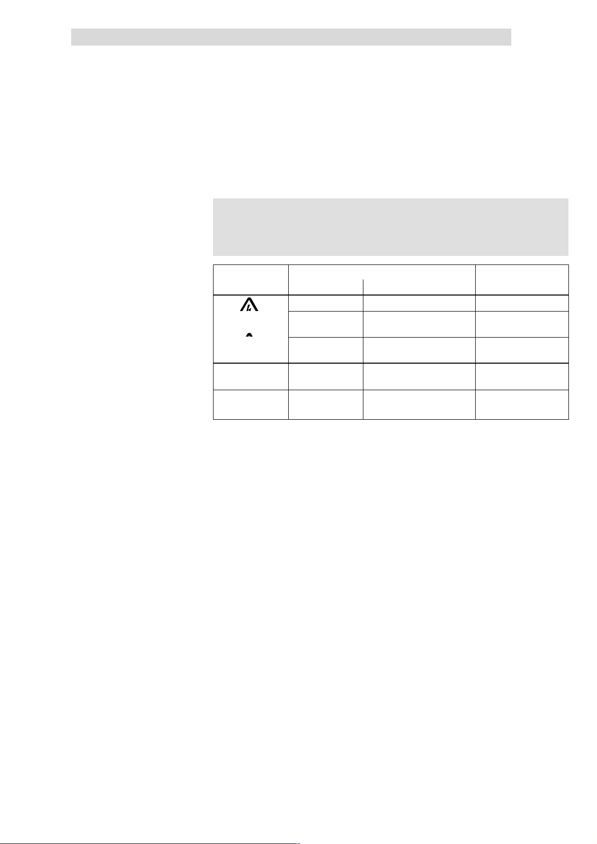
Safety information
{
}
Show/Hide Bookmarks
3
Layout of safety notes
3.5 Layout of safety notes
All safety information given in these Instructions have got the same layout:
}
} Signal word! (indicates the severity of danger)
}}
Pictograph
Dangerous electrical voltage
General danger
(
)
Pictograph (indicates the type of danger)
Note (describes the danger and explains how to avoid it)
Signal word
Signal word Meaning
Danger! Impending danger for persons Death or most severe injuries
Warning! Possible, very dangerous
situation for persons
Caution! Possible, dangerous situation for
persons
Stop! Possible material damage Damage of the drive system
Note! Useful note or tip
If you observe it, handling of the
drive system will be easier.
Possible consequences if
the safety information are
disregarded
Death or most severe injuries
Injuries
or its surroundings
3.5
L
EDS 82EV903-1.0-11/2002
3.5-1
Page 52

Show/Hide Bookmarks
Page 53

Technical data
Show/Hide Bookmarks
4
Contents
4 Technical data
4.1 Contents
4.1 Contents 4.1-1................................................................
4.2 General data/application conditions 4.2-1............................................
4.3 Operation with rated power (normal operation) 4.3-1....................................
4.3.1 Rated data for mains voltage 230 V 4.3-1....................................
4.3.2 Rated data for mains voltage 400 V 4.3-5...................................
4.3.3 Rated data for mains voltage 500 V 4.3-10....................................
4.4 Operation with increased rated power 4.4-1..........................................
4.4.1 Rated data for mains voltage 230 V 4.4-1....................................
4.4.2 Rated data for mains voltage 400 V 4.4-4....................................
4.4.3 Mains voltage 500 V 4.4-9...............................................
4.1
L
EDS 82EV903-1.0-11/2002
4.1-1
Page 54

Show/Hide Bookmarks
Page 55
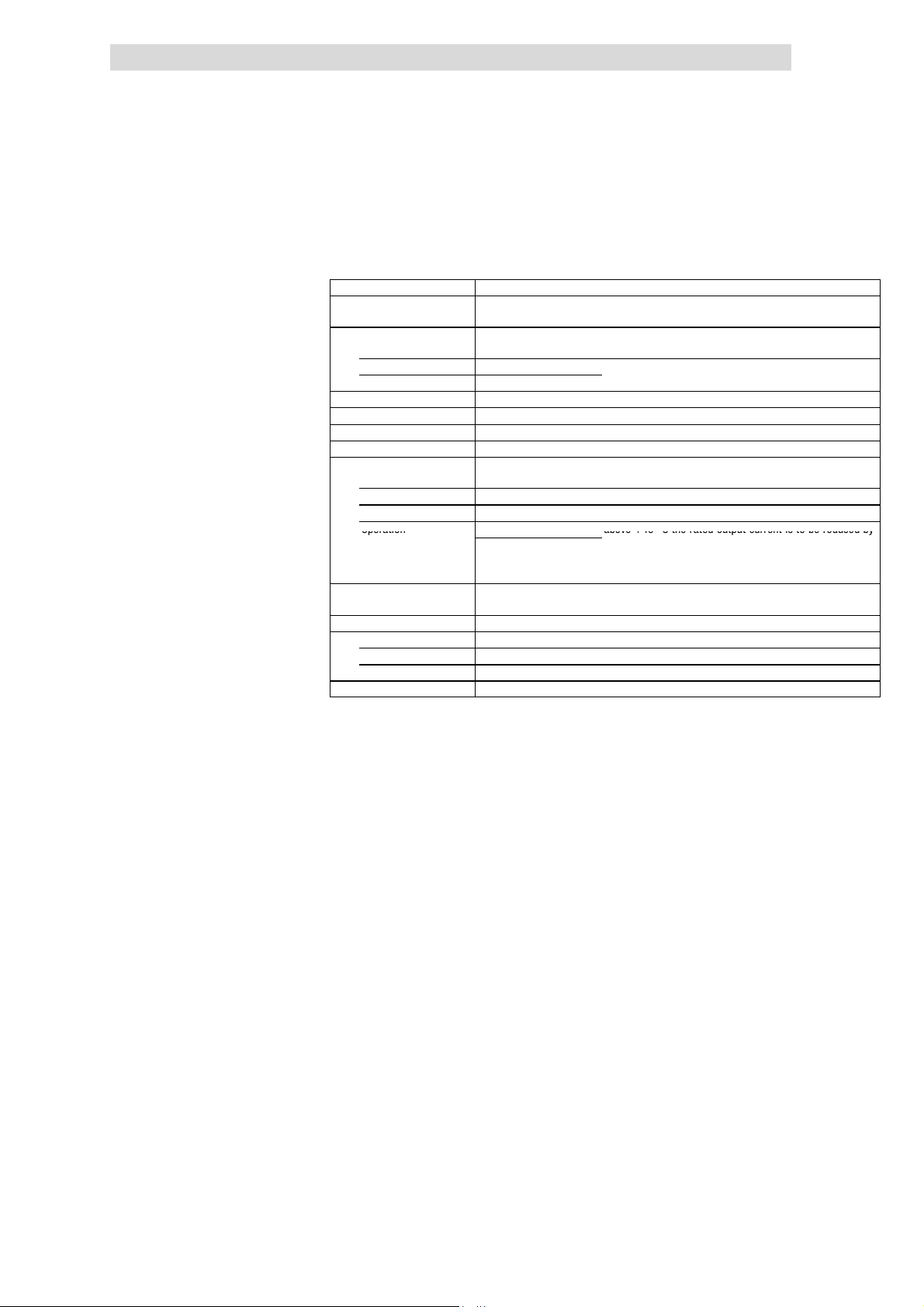
Technical data
ForcompliancewithEMCregulations,thepermissibl
e
Operation
above+40Ctheratedoutputcurrentistobereducedby
Show/Hide Bookmarks
4
General data/application conditions
4.2 General data/application conditions
Standards and application
conditions
Conformity CE Low-Voltage Directive (73/23/EEC)
Approvals UL 508C Underwriter Laboratories (File-No. E132659)
Max. permissible motor
cable length
shielded 50 m
unshielded 100 m
Vibration resistance Acceleration resistance up to 0.7g (Germanischer Lloyd, general conditions)
Climatic conditions Class 3K3 to EN 50178 (without condensation, a verage relative humidity 85 %)
Degree of pollution VDE 0110 part 2 pollution degree 2
Packaging (DIN 4180) Dust packaging
Permissible temperature
ranges
Transport -25°C...+70°C
Storage -25°C...+60°C
Operation -10°C...+55°C above +40 °C the rated output current is to be reduced by
Permissible installation
height
Mounting positions vertical
Mounting clearances
above/below ≥100 mm
to the sides Side-by-side mounting with a distance of 3 mm
DC group operation possible, except E82EV251K2C and E82EV371K2C
For rated mains voltage and chopper frequency of 8 kHz without additional output
filters
-10°C...+50°C
(o nl y 8200 ve ct o r
15 ... 90 k W)
0 ... 4000 m amsl above 1000 m amsl the rated output current is to be
4.2
Power Conversion Equipment
For compliance with EMC regulations, thepermissible
cable lengths must be changed
2.5 %/°C
reduced by 5 %/1000 m
L
EDS 82EV903-1.0-11/2002
4.2-1
Page 56
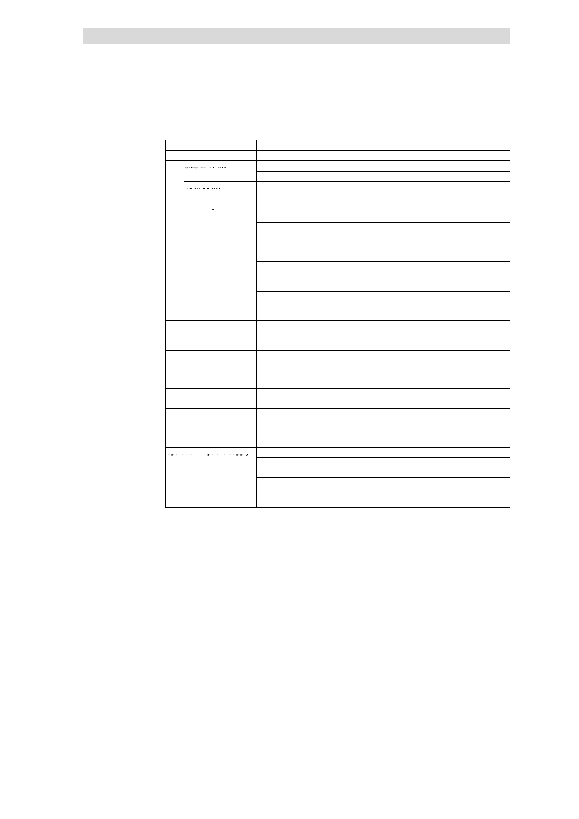
4
0.25...11kW
15...90kW
Noiseimmunity
Operationinpublicsupply
Show/Hide Bookmarks
Technical data
4.2
General technical data
General data/application conditions
EMC Compliance with EN 61800-3/A11
Noise emission Compliance with limit value classes A and B to EN 55011
0.25 ... 11 kW E82xVxxxKxC0xx without additional measures
E82xVxxxKxC2xx by means of external filters
15 ... 90 kW E82EVxxxK4B3xx without additional measures
E82xVxxxK4B2xx by means of external filters
Noise immunity Requirements to EN 61800-3 incl. A11 noise immunity
Requirements Standard Severities
ESD EN 61000-4-2 3, i.e. 8 kV with air discharge,
High frequency in cables EN 61000-4-6 150 kHz ... 80 MHz,
RF interference
(enclosure)
Burst EN 61000-4-4 3/4, i. e. 2 kV/5 kHz
Surge
(Surge on mains cable)
Insulation resistance Overvoltage categor y III acc. to VDE 0110
Discharge current to PE (to
EN 50178)
Enclosure IP20
Protection measures
against
Insulation of control
circuits
Permissible mains types Operation at TT systems, TN systems or systems with grounded star point without
Operation in public supply Li mit at i on of harmonic currents according to EN 61000-3-2
networks
1)
The additional measures described only ensure that the controllers meet the requirements o f the EN 61000-3-2.
The machine/system manufacturer is responsible for the compliance with the regulations of the machine!
>3.5mA,
i. e. fixed installation and double PE connection are required.
Short circuit, earth fault (earth-fault protected during operation, limited earth-fault
protection during power up), motor stalling, motor overtemperature (input for PTC or
thermal contact, I
Safe mains isolation: Double/reinforced insulation to EN 50178
additional measures
Operation at IT systems is only possible with variant ”1xx” of the 8200 vector basic
devices 15 ... 90 kW
Total power connected to
the mains
<0.5kW With mains choke
0.5kW...1kW With active filter (in preparation)
>1kW Without additional measures
EN 61000-4-3 80 MHz ... 1000 MHz,
EN 61000-4-5 3, i. e. 1.2/50 µs,
2
t monitoring)
Compliance with the requirements
6 kV with contact discharge
10 V/m 80 % AM (1kHz)
10 V/m 80 % AM (1kHz)
1 kV phase-phase,
2 kV phase-PE
1)
4.2-2
EDS 82EV903-1.0-11/2002
L
Page 57
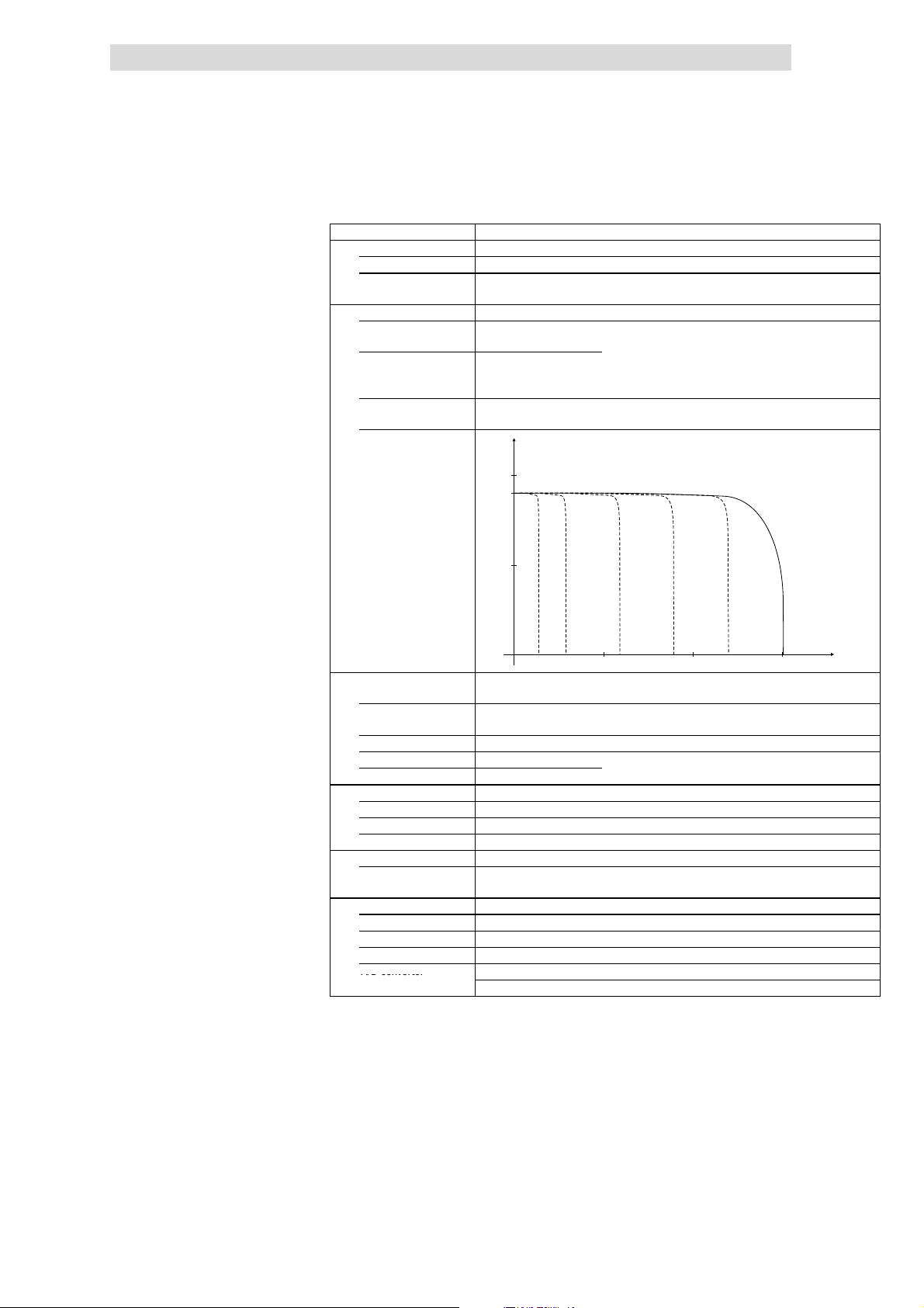
Technical data
A/Dconverte
r
Show/Hide Bookmarks
4
General data/application conditions
Control
Control types V/f characteristic control (linear/square-law), vector control, torque selection
Chopper frequency
Torque characteristic
0.25 ... 11 kW 2kHz,4kHz,8kHz,16kHzwithoptimisednoiselevel
15 ... 90 kW 1 kHz, 2 kHz, 4 kHz, 8 kHz, 16 kHz,
Maximum torque
0.25 ... 11 kW
Maximum torque
15 ... 90 kW
Setting range 1:10 over the speed range of 3 ... 50 Hz,
Torque/speed
characteristic
optionally with optimised noise level or optimised power loss
1.8 x Mrfor 60s if rated motor power = rated controller power
1.8 x Mrfor 60s
for 3 s after
2.1 x M
r
controller enable
accuracy < 8 %
M/M
N
2.0
1.8
1.0
4.2
500 1000 1500
Vector control (sensorless
speed control)
Minimum output
frequency
Setting range 1:50 Ref. to 50 Hz and M
Accuracy ± 0.5 %
Smooth running ± 0.1 Hz
Output frequency
Field - 650 Hz ... + 650 Hz
Absolute resolution 0.02 Hz
Normalised resolution Parameter data: 0.01 %, process data: 0.006 % (= 214)
Digital setpoint selection
Accuracy ± 0.0001 %
Analog setpoint selection
Linearity ± 0.5 % related to instantaneous value
Temperature sensitivity + 0.3 % (0 ... +60 °C) related to instantaneous value
Offset ± 0%
A/D converter Resolution 10 bits
1.0Hz(0...Mr)
over the speed range 3 ... 50 Hz
Fault 1 digit ≡ 0.1 % related to final value
-1
n [min ]
r
L
EDS 82EV903-1.0-11/2002
4.2-3
Page 58
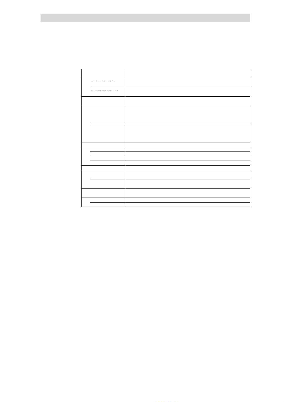
4
WithstandardI/O
WithapplicationI/
O
Show/Hide Bookmarks
Technical data
4.2
Inputs and outputs
Analog inputs
Analog outputs
With standard I/O
With application I/O
Digital inputs
Digital outputs
With standard I/O
With application I/O
Cycle times
Digital inputs 1ms
Digital outputs 4ms
Analog inputs 2msec
Analog outputs 4 ms (smoothing time: τ =10ms)
Relay output
0.25 ... 11 kW 1 relay output
15 ... 90 kW 2 relay outputs
Operation in generator
mode
0.25 ... 11 kW Integrated brake transistor
15 ... 90 kW With brake chopper 8253 or 9352
1 input, optionally bipolar
1 output
2 inputs, optionally bipolar
2 inputs, optionally bipolar
4 inputs optionally 1 frequency input single-track 0 ... 10 kHz or
1 input for controller inhibit
1 output
6 inputs optionally 1 frequency input single-track/double-track 0 ...
1 input for controller inhibit
2 outputs, 1 frequency output 50 Hz ... 10 kHz
(changeover contact)
(changeover contact)
General data/application conditions
double-track 0 ... 1 kHz
100 k Hz;
AC 250 V/3 A, DC 24 V/2 A ... 240 V/0.16 A
AC 250 V/3 A, DC 24 V/2 A ... 240 V/0.22 A
4.2-4
EDS 82EV903-1.0-11/2002
L
Page 59
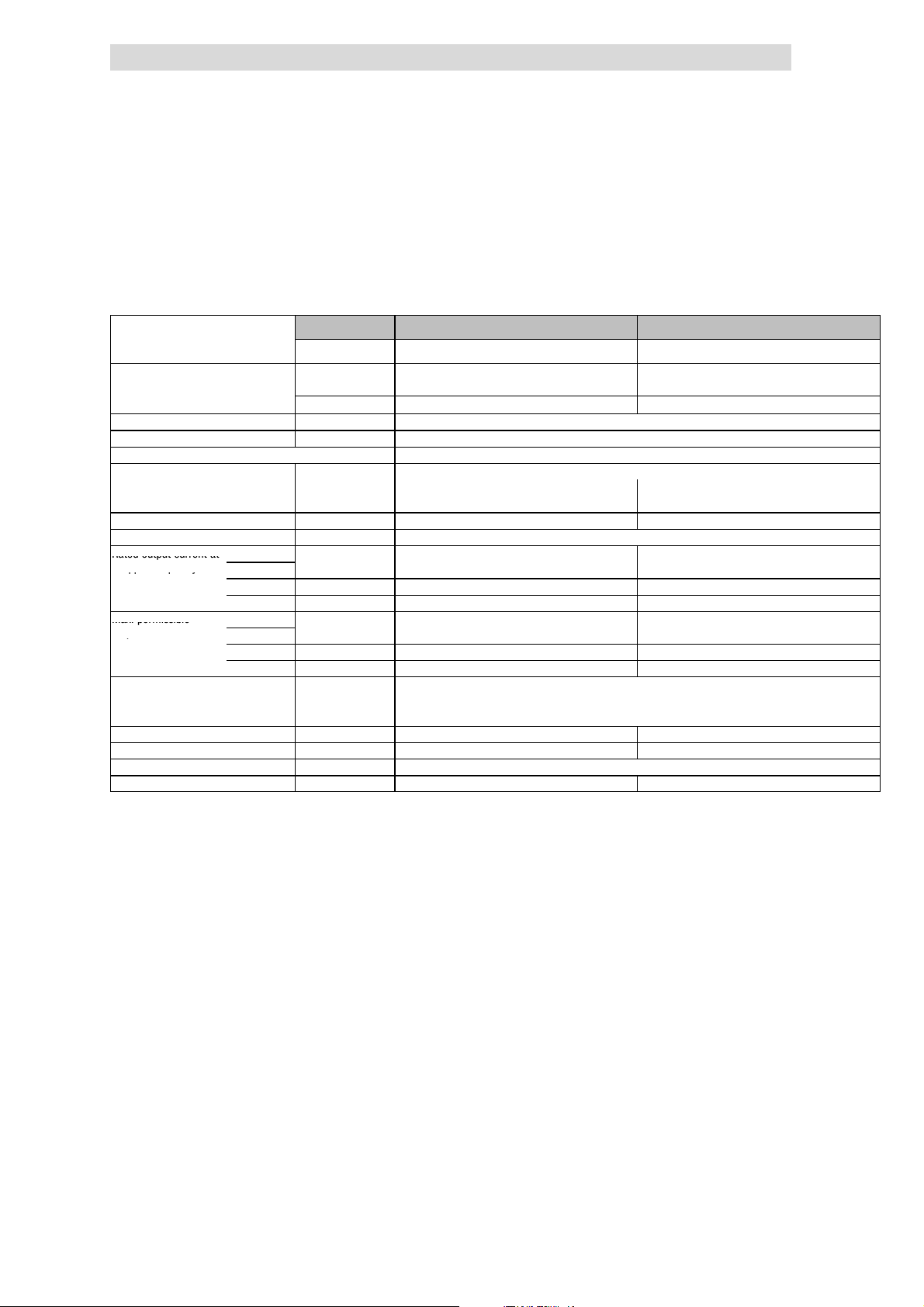
Technical data
Ratedoutputcurrenta
t
5
)
ppq
y
Max.permissible
p
Show/Hide Bookmarks
4
Operation with rated power (normal operation)
Rated data for mains voltage 230 V
4.3 Operation with rated power (normal operation)
4.3.1 Rated data for mains voltage 230 V
Typical motor power
Three-phaseAC asynchronous motor
(4 pole)
8200 vector type EMC filt er
Mains voltage U
Alternative DC supply UDC[V] not possible
Data for operation with 1/N/PE AC 230 V
Rated mains current
without mains choke I
with mains choke I
Output power U, V, W Sr[kVA] 0.68 1.0
Output power +UG,-U
Rated output current at 2kHzsin
chopper frequency
Max. permissible 2kHzsin
output current for 60 s
at chopper frequency
Output voltage
Power loss (operation with Ir8) Pv[W] 30 40
Required mains choke Type - Dimensions H x W x D [mm] 120 x 60 x 140
Weight m[kg] 0.8 0.8
2)
G
4kHzsin
8kHzsin Ir[A] 1.7 2.4
16 kH z sin
4kHzsin
3)
8kHzsin I
16 kH z sin
without mains choke UM[V] 3~ 0 ... V
with mains choke UM[V] 3~ 0 ... approx. 94 % U
Pr[kW] 0.25 0.37
Pr[hp] 0.34 0.5
integrated
Without EMC filter E82EV251K2C2xx E82EV371K2C2xx
[V] 1/N/PE AC 180 V - 0 % ... 264 V + 0 % ; 45 Hz - 0 % ... 65 Hz + 0 %
mains
[A] 3.4 5.0
mains
[A] 3.0 4.2
mains
PDC[kW] DC bus operation not possible
Ir[A]
4)
4)
Ir[A] 1.1 1.6
I
[A] 2.5 3.6
max
[A] 2.5 3.6
max
I
[A] 1.7 2.3
max
Printed in bold = Data for operation at 8 kHz chopper frequency (Lenze setting)
3)
Currents for periodic load change: 1 min overcurrent with I
4)
Chopper frequency is reduced to 4 kHz if ϑ
5)
Possible for other types with different application conditions: Operation with increased rated output current and
the same load change
E82EV251K2C0xx E82EV371K2C0xx
1.7 2.4
/ 0 ... 650 Hz
(¶ 4.4-1)
reaches - 5 °C
max
mains
max
/ 0 ... 650 Hz
mains
and 2 min basic load with 75 % I
4.3
4.3.1
r
L
EDS 82EV903-1.0-11/2002
4.3-1
Page 60
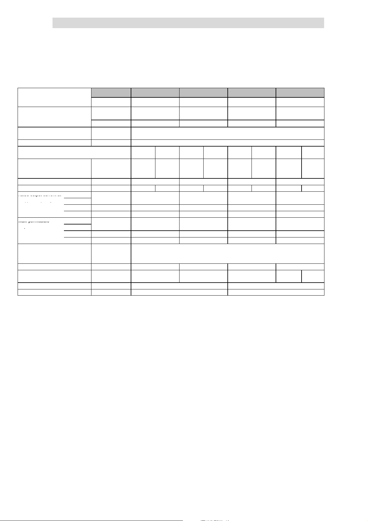
4
Ratedoutputcurrenta
t
5
)
ppq
y
Max.permissible
p
Show/Hide Bookmarks
Technical data
4.3
4.3.1
Typical motor power
Three-phaseAC asynchronous motor
(4 pole)
8200 vector type EMC filt er
Mains voltage U
Alternative DC supply UDC[V] DC 140 V - 0 % ... 370 V + 0 %
Data for operation with 1/N/PE (3/PE) AC 230 V or DC
325 V
Rated mains current
without mains choke I
with mains choke I
Output power U, V, W Sr[kVA] 1.2 1.6 2.8 3.8
Output power +UG,-U
Rated output current at 2kHzsin
chopper frequency
Max. permissible 2kHzsin
output current for 60 s
at chopper frequency
Output voltage
without mains choke/mains filter UM[V] 3~ 0 ... V
with mains choke/mains filter UM[V] 3~ 0 ... approx. 94 % U
Power loss (operation with Ir8) Pv[W] 50 60 100 130
Required mains choke Type - - - ELN1- 0250H018 -
2)
G
4kHzsin
8kHzsin Ir[A] 3.0 4.0 7.0 9.5
16 kH z sin
4kHzsin
3)
8kHzsin I
16 kH z sin
Pr[kW] 0.55 0.75 1.5 2.2
Pr[hp] 0.75 1.0 2.0 3.0
integrated
Without EMC filter E82EV551K2C2xx E82EV751K2C2xx E82EV152K2C2xx E82EV222K2C2xx
[V] 1/N/PE AC 180 V - 0 % ... 264 V + 0 % ; 45 Hz - 0 % ... 65 Hz + 0 %
mains
[A] 6.0 3.9 9.0 5.2 15.0 9.1 - 12.4
mains
[A] 5.6 2.7 7.5 3.6 12.5 6.3 18.0 9.0
mains
PDC[kW] - 0.3 - 0.1 - 1.1 - 0.4
Ir[A]
4)
4)
Ir[A] 2.0 2.6 4.6 6.2
I
[A] 4.5 6.0 10.5 14.2
max
[A] 4.5 6.0 10.5 14.2
max
I
[A] 2.9 3.9 6.9 9.3
max
E82EV551K2C0xx E82EV751K2C0xx E82EV152K2C0xx E82EV222K2C0xx
3/PE AC 100 V - 0 % ... 264 V + 0 % ; 45 H z - 0 % ... 65 Hz + 0 %
1/N/PE 3/PE 1/N/PE 3/PE 1/N/PE 3/PE 1/N/PE
3.0 4.0 7.0 9.5
Operation with rated power (normal operation)
Rated data for mains voltage 230 V
1)
/ 0 ... 650 Hz
mains
mains
/ 0 ... 650 Hz
3/PE
Dimensions H x W x D [mm] 180 x 60 x 140 240 x 60 x 140
Weight m[kg] 1.2 1.6
Printed in bold = Data for operation at 8 kHz chopper frequency (Lenze setting)
1)
Operation only with mains choke
2)
For operation with power-adapted motors additional power to be taken from the DC bus
3)
Currents for periodic load change: 1 min overcurrent with I
4)
Chopper frequency is reduced to 4 kHz if ϑ
5)
With different application conditions for other types possible: Operation with increased rated output current and
the same load change
(¶ 4.4-1)
reaches - 5 °C
max
and 2 min basic load with 75 % I
max
r
4.3-2
EDS 82EV903-1.0-11/2002
L
Page 61
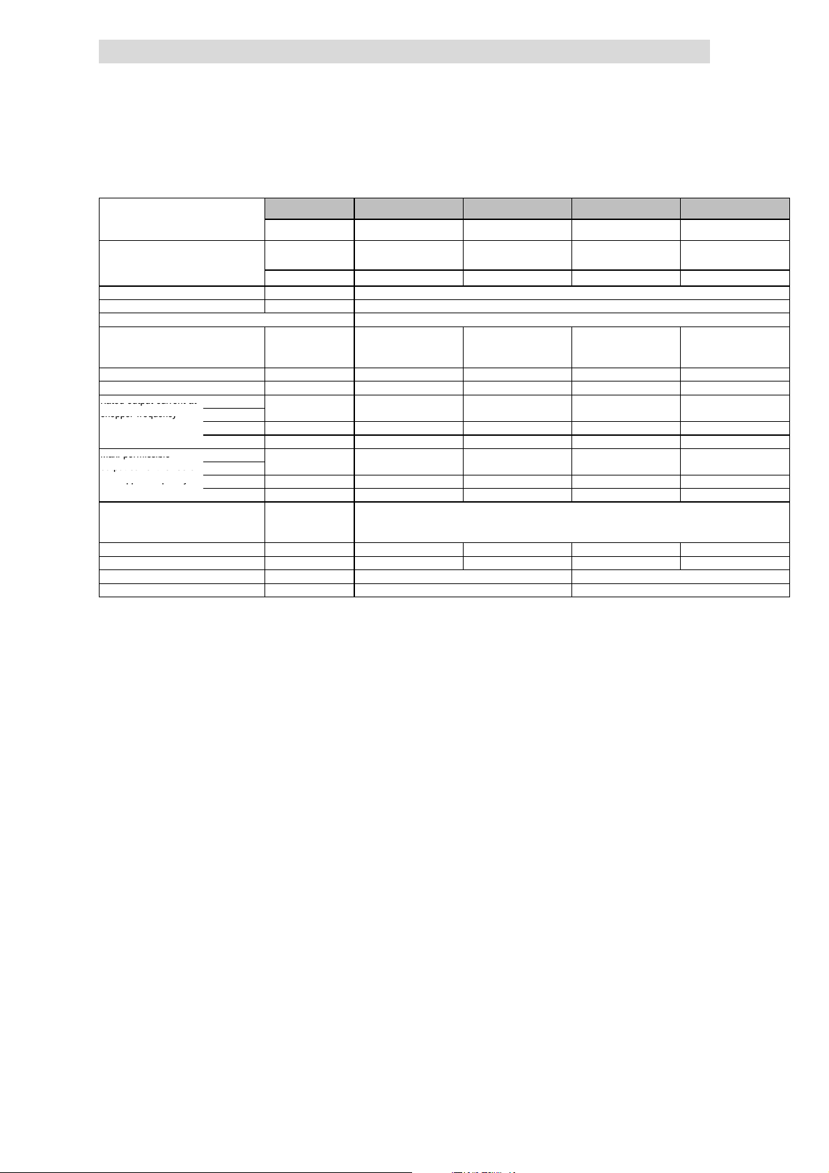
Technical data
5
)
Ratedoutputcurrenta
t
Ir[A]
5
)
1
2.019.822.52
8.6chopperfrequency
Max.permissible
I
[A]18.024.833.842.9outputcurrentfor60
s
ppq
y
Show/Hide Bookmarks
4
Operation with rated power (normal operation)
Rated data for mains voltage 230 V
Typical motor power
Three-phaseAC asynchronous motor
(4 pole)
8200 vector type EMC filt er
Mains voltage U
Alternative DC supply UDC[V] DC 140 V - 0 % ... 370 V + 0 %
Data for operation with 3/PE AC 230 V or DC 325 V
Rated mains current
Output power U, V, W Sr[kVA] 4.8 6.6 9.0 11.4
Output power +UG,-U
Rated output current at
chopper frequency
Max. permissible
output current for 60 s
at chopper frequency
Output voltage
without mains choke/mains filter UM[V] 3~ 0 ... V
Power loss (operation with Ir8) Pv[W] 150 190 250 320
Required mains choke Type - - - ELN3-0088H035
Dimensions H x W x D [mm] 240 x 100 x 140 240 x 125 x 140
Weight m[kg] 2,9 3.6
without mains choke I
with mains choke I
2)
G
2kHzsin
4kHzsin
8kHzsin Ir[A] 12.0 16.5 22.5 28.6
16 kH z sin
2kHzsin
4kHzsin
3)
8kHzsin I
16 kH z sin
with mains choke/mains filter UM[V] 3~ 0 ... approx. 94 % U
Pr[kW] 3.0 4.0 5.5 7.5
Pr[hp] 4.1 5.4 7.5 10.2
integrated
without EMC filter E82EV302K2C2xx E82EV402K2C2xx E82EV552K2C2xx E82EV752K2C2xx
4)
4)
[V] 3/PE AC 100 V - 0 % ... 264 V + 0 % ; 45 Hz - 0 % ... 65 Hz + 0 %
mains
[A] 15.6 21.3 29.3 -
mains
[A] 12.0 16.0 21.0 28.0
mains
PDC[kW] 0.9 0.8 1.1 0
Ir[A] 7.8 10.7 14.6 18.6
max
[A] 18.0 24.8 33.8 42.9
max
I
[A] 11.7 16.1 21.9 27.9
max
Printed in bold = Data for operation at 8 kHz chopper frequency (Lenze setting)
1)
Operation only with mains choke
2)
For operation with power-adapted motors additional power to be taken from the DC bus
3)
Currents for periodic load change: 1 min overcurrent with I
4)
Chopper frequency is reduced to 4 kHz if ϑ
5)
With different application conditions for other types possible: Operation with increased rated output current and
the same load change
E82EV302K2C0xx E82EV402K2C0xx E82EV552K2C0xx E82EV752K2C0xx
/ 0 ... 650 Hz
(¶ 4.4-1)
reaches - 5 °C
max
mains
max
/ 0 ... 650 Hz
mains
and 2 min basic load with 75 % I
r
4.3
4.3.1
1)
1)
L
EDS 82EV903-1.0-11/2002
4.3-3
Page 62
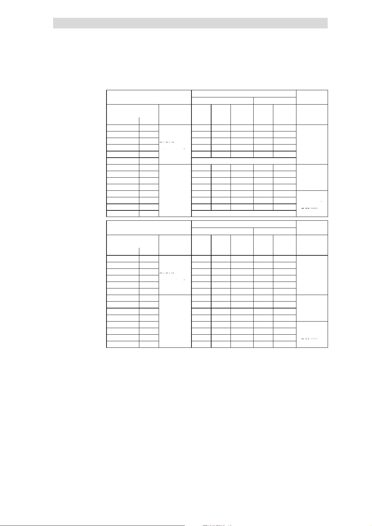
4
1/N/PEA
C
2/PEA
C
A
2
)
180...264V;
A
3
)
A
≥
300mA
)
≥
30m
A
1/N/PEA
C
2/PEA
C
A
2
)
806
;
A
3
)
A
≥
300mA
)
≥
30m
A
Show/Hide Bookmarks
Technical data
4.3
4.3.1
Fusesand cable cross-sections
(operation with rated power,
mains voltage 230V)
Operation with rated power (normal operation)
Rated data for mains voltage 230 V
Operation without mains choke
Installation to EN 60204-1 Installation to UL
8200 vector Mains L1, L2, L3,
Type [kW] [mm2] [AWG]
E82EV251K2C 0.25 M10 A C10 A 1.5 10 A 16
E82EV371K2C 0.37
E82EV551K2C 0.55
E82EV751K2C 0.75
E82EV152K2C 1.5
E82EV222K2C 2.2 Operation only with mains choke
E82EV551K2C 0.55 M6 A B6 A 1 5A 18
E82EV751K2C 0.75 M10 A B10 A 1.5 10 A 16
E82EV152K2C 1.5
E82EV222K2C 2.2
E82EV302K2C 3.0
E82EV402K2C 4.0
E82EV552K2C 5.5 M35 A - 66) 35 A 8
E82EV752K2C 7.5 Operation only with mains choke
8200 vector Mains L1, L2, L3,
Type [kW] [mm2] [AWG]
E82EV251K2C 0.25 M10 A C10 A 1.5 10 A 16
E82EV371K2C 0.37
E82EV551K2C 0.55
E82EV751K2C 0.75
E82EV152K2C 1.5
E82EV222K2C 2.2 M20 A B20 A 2x1.5 20 A 2x16
E82EV551K2C 0.55 M6 A B6 A 1 5A 18
E82EV751K2C 0.75 M6 A B6 A 1 5A 18
E82EV152K2C 1.5
E82EV222K2C 2.2
E82EV302K2C 3.0
E82EV402K2C 4.0
E82EV552K2C 5.5 M25 A B25 A 4 25 A 10
E82EV752K2C 7.5 M35 A - 6
Fuse
E.l.c.b.
1)
Use UL-approved cables, fuses and fuse holders only.
UL fuse: voltage 240 V, tripping characteristic ”H” or ”K5”
2)
Pulse-current or universal-current sensitive earth leakage circuit breaker
3)
All-current sensitive e.l.c.b.
4)
All-current sensitive e.l.c.b. for use with E82EVxxxK2C0xx
5)
All-current sensitive e.l.c.b. for use with E82EVxxxK2C2xx
6)
Flexible cable can only be connected using pin end connectors.
Observe national and regional regulations (e. g. VDE 0113, EN 60204)
1/N/PEAC
2/PE AC M10 A B10 A 1.5 10 A 16
180 ... 264 V;
45 ... 65 Hz
3/PE AC
100 ... 264V;
45 ... 65 Hz
1/N/PEAC
2/PE AC M10 A B10 A 1.5 10 A 16
180 ... 264 V;
45 ... 65 Hz
3/PE AC
100 ... 264V;
45 ... 65 Hz
M10 A C10 A 1.5 10 A 16
M16 A B16 A 2.5 15 A 14
M20 A B20 A 2x1.5 20 A 2x16
M16 A B16 A 2.5 15 A 14
M16 A B16 A 2.5 15 A 14
M20 A B20 A 4 20 A 12
M25 A B25 A 4 25 A 10
Operating with mains choke
Installation to EN 60204-1 Installation to UL
M10 A C10 A 1.5 10 A 16
M10 A B10 A 1.5 10 A 16
M16 A B16 A 2x1.5 15 A 2x16
M10 A B10 A 1.5 10 A 16
M10 A B10 A 1.5 10 A 16
M16 A B16 A 2.5 15 A 14
M20 A B20 A 4 20 A 12
PE
PE
6)
L1, L2, L3,
PE
L1, L2, L3,
PE
35 A 8
1)
FI
≥ 30 m
≥ 30 m
≥ 300 m
≥ 30 mA
1)
≥ 30 m
≥ 30 m
≥ 300 m
≥ 30 mA
4)
5)
FI
4)
5)
4.3-4
EDS 82EV903-1.0-11/2002
L
Page 63

Technical data
Ratedoutputcurrenta
t
5
)
ppq
y
Max.permissible
p
Show/Hide Bookmarks
4
Operation with rated power (normal operation)
Rated data for mains voltage 400 V
4.3.2 Rated data for mains voltage 400 V
Typical motor power
Three-phaseAC asynchronous motor
(4 pole)
8200 vector type EMC filt er
Mains voltage U
Alternative DC supply UDC[V] DC 450 V - 0 % ... 775 V + 0 %
Data for operation with 3/PE AC 400 V or DC 565 V
Rated mains current
without mains choke I
with mains choke I
Output power U, V, W Sr[kVA] 1.3 1.7 2.7 3.9
Output power +UG,-U
Rated output current at 2kHzsin
chopper frequency
Max. permissible 2kHzsin
output current for 60 s
at chopper frequency
Output voltage
Power loss (operation with Ir8) Pv[W] 50 60 100 130
Required mains choke Type - - - Required brake resistor
Dimensions H x W x D [mm] 180 x 60 x 140 240 x 60 x 140
Weight m[kg] 1.2 1.6
2)
G
4kHzsin
8kHzsin Ir[A] 1.8 2.4 3.9 5.6
16 kH z sin
4kHzsin
3)
8kHzsin I
16 kH z sin
without mains choke UM[V] 3~ 0 ... V
with mains choke UM[V] 3~ 0 ... approx. 94 % U
6)
Pr[kW] 0.55 0.75 1.5 2.2
Pr[hp] 0.75 1.0 2.0 3.0
integrated
Without EMC filter E82EV551K4C2xx E82EV751K4C2xx E82EV152K4C2xx E82EV222K4C2xx
[V] 3/PE AC 320 V - 0 % ... 550 V + 0 % ; 45 Hz - 0 % ... 65 Hz + 0 %
mains
[A] 2.5 3.3 5.5 7.3
mains
[A] 2.0 2.3 3.9 5.1
mains
PDC[kW] 0.3 0.1 1.1 0.4
Ir[A]
4)
4)
Ir[A] 1.2 1.6 2.5 3.6
I
[A] 2.7 3.6 5.9 8.4
max
[A] 2.7 3.6 5.9 8.4
max
I
[A] 1.8 2.4 3.8 5.5
max
Type ERBM470R100W ERBM370R150W ERBM240R200W
Printed in bold = Data for operation at 8 kHz chopper frequency (Lenze setting)
2)
For operation with power-adapted motors additional power to be taken from the DC bus
3)
Currents for periodic load change: 1 min overcurrent with I
4)
Chopper frequency is reduced to 4 kHz if ϑ
5)
Possible for other types with different application conditions: Operation with increased rated output current and
the same load change
6)
Operation at mains voltages 484 V - 0 % ... 550 V + 0 % is only permissible with brake resistor!
E82EV551K4C0xx
1.8 2.4 4.7 5.6
6)
(¶ 4.4-4)
E82EV751K4C0xx
max
6)
mains
max
reaches - 5 °C
E82EV152K4C0xx
/ 0 ... 650 Hz
/ 0 ... 650 Hz
mains
and 2 min basic load with 75 % I
6)
E82EV222K4C0xx
r
4.3
4.3.2
6)
L
EDS 82EV903-1.0-11/2002
4.3-5
Page 64
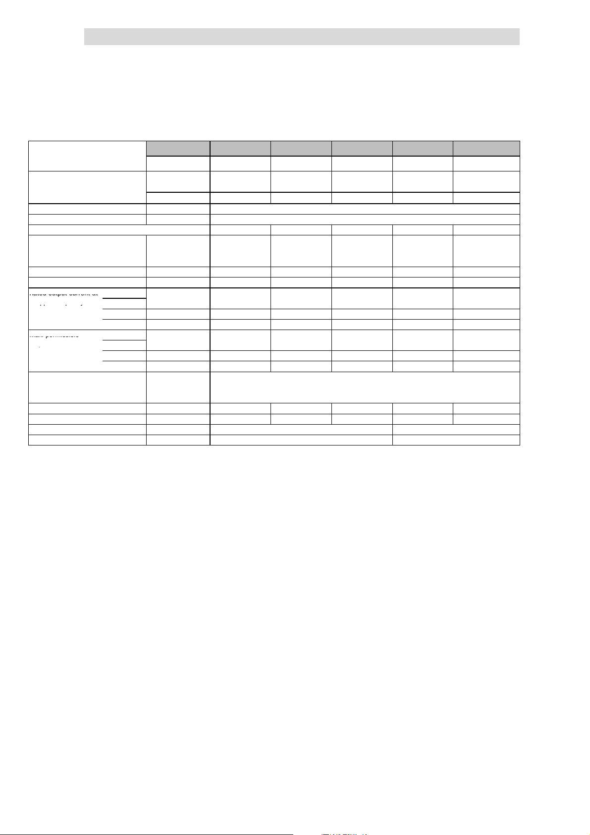
4
Ratedoutputcurrenta
t
5
)
ppq
y
Max.permissible
p
Show/Hide Bookmarks
Technical data
4.3
4.3.2
Typical motor power
Three-phaseAC asynchronous motor
(4 pole)
8200 vector type EMC filt er
Mains voltage U
Alternative DC supply UDC[V] DC 450 V - 0 % ... 775 V + 0 %
Data for operation with 3/PE AC 400 V or DC 565 V
Rated mains current
without mains choke I
with mains choke I
Output power U, V, W Sr[kVA] 5.1 6.6 9.0 11.4 16.3
Output power +UG,-U
Rated output current at 2kHzsin
chopper frequency
Max. permissible 2kHzsin
output current for 60 s
at chopper frequency
Output voltage
Power loss (operation with Ir8) Pv[W] 145 180 230 300 410
Required mains choke Type - - - - ELN3-150H024
Dimensions H x W x D [mm] 240 x 100 x 140 240 x 125 x 140
Weight m[kg] 2.9 3.6
2)
G
4kHzsin
8kHzsin Ir[A] 7.3 9.5 13.0 16.5 23.5
16 kH z sin
4kHzsin
3)
8kHzsin I
16 kH z sin
without mains choke UM[V] 3~ 0 ... V
with mains choke UM[V] 3~ 0 ... approx. 94 % U
Pr[kW] 3.0 4.0 5.5 7.5 11
Pr[hp] 4.1 5.4 7.5 10.2 15
integrated
Without EMC filter E82EV302K4C2xx E82EV402K4C2xx E82EV552K4C2xx E82EV752K4C2xx E82EV113K4C2xx
mains
mains
mains
PDC[kW] 1.7 0.8 1.1 1.5 0
Ir[A]
4)
4)
Ir[A] 4.7 6.1 8.4 10.7 13.0
I
[A] 11.0 14.2 19.5 24.8 35.3
max
[A] 11.0 14.2 19.5 24.8 35.3
max
I
[A] 7.0 9.1 12.6 16.0 19.5
max
Printed in bold = Data for operation at 8 kHz chopper frequency (Lenze setting)
1)
2)
3)
4)
5)
E82EV302K4C0xx E82EV402K4C0xx E82EV552K4C0xx E82EV752K4C0xx E82EV113K4C0xx
[V] 3/PE AC 320 V - 0 % ... 550 V + 0 % ; 45 Hz - 0 % ... 65Hz + 0 %
[A] 9.0 12.3 16.8 21.5 [A] 7.0 8.8 12.0 15.0 21.0
7.3 9.5 13.0 16.5 23.5
Operation only with mains choke
For operation with power-adapted motors additional power to be taken from the DC bus
Currents for periodic load change: 1 min overcurrent with I
Chopper frequency is reduced to 4 kHz if ϑ
With different application conditions for other types possible: Operation with increased rated output current and
the same load change
(¶ 4.4-4)
Operation with rated power (normal operation)
Rated data for mains voltage 400 V
/ 0 ... 650 Hz
reaches - 5 °C
max
mains
max
/ 0 ... 650 Hz
mains
and 2 min basic load with 75 % I
r
1)
1)
4.3-6
EDS 82EV903-1.0-11/2002
L
Page 65
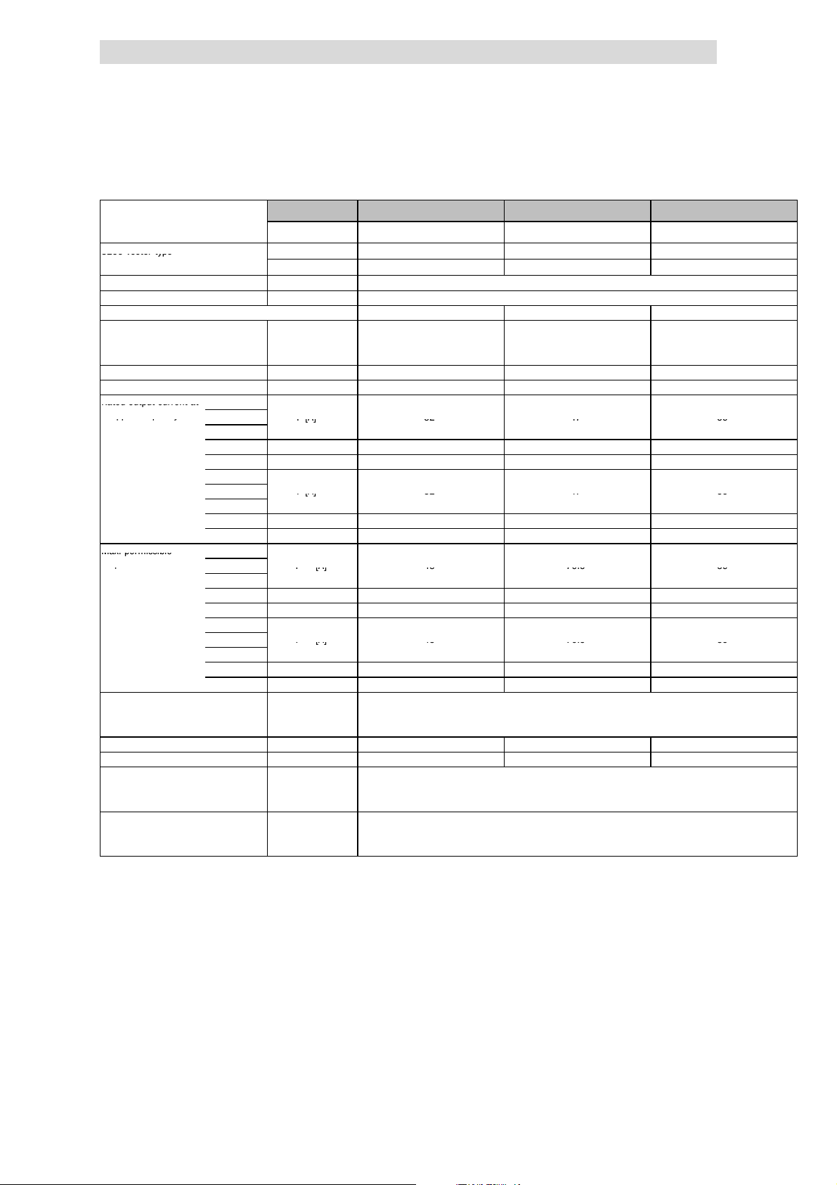
Technical data
8200vectortyp
e
Ratedoutputcurrenta
t
ppq
y
Ir[A]324759
Ir[A]324759
Max.permissible
p
I
max
[A]4870.589
I
max
[A]4870.589
Show/Hide Bookmarks
4
Operation with rated power (normal operation)
Rated data for mains voltage 400 V
Typical motor power
Three-phaseAC asynchronous motor
(4 pole)
8200 vector type With mains filter E82EV153K4B3xx E82EV223K4B3xx E82EV303K4B3xx
Mains voltage U
Alternative DC supply UDC[V] DC 450 V - 0 % ... 775 V + 0 %
Data for operation with 3/PE AC 400 V or DC 565 V
Rated mains current
Without mains choke I
With mains choke I
Output power U, V, W Sr[kVA] 22.2 32.6 41.6
Output power +UG,-U
Rated output current at 1kHzsin
chopper frequency
Max. permissible 1kHzsin
output current for 60 s
at chopper frequency
Output voltage
Power loss (operation with Ir8) Pv[W] 430 640 810
Required mains choke type] - ELN3-0075H045 ELN3-0055H055
Dimensions
Weight
2)
G
2kHzsin Ir[A]
4kHzsin
8kHzsin Ir[A] 29 43 47
16 kH z sin
1kHz
2kHz Ir[A]
4kHz
8kHz Ir[A] 32 47 59
4)
16 k Hz
2kHzsin I
3)
4kHzsin
8kHzsin I
16 kH z sin
1kHz
2kHz I
4kHz
8kHz I
4)
16 k Hz
without mains choke UM[V] 3~ 0 ... V
with mains choke UM[V] 3~ 0 ... approx. 94 % U
with mains filter H x W x D [mm] 350 x 250 x 340
without mains filter H x W x D [ mm] 350 x 250 x 250
with mains filter m[kg] 34
without mains filter m[kg] 15
Pr[kW] 15 22 30
Pr[hp] 20 30 40
Without mains filter E82EV153K4B2xx E82EV223K4B2xx
[V] 3/PE AC 320 V - 0 % ... 550 V + 0 % ; 45 Hz - 0 % ... 65 Hz + 0 %
mains
[A] 43.5 - -
mains
[A] 29.0 42.0 55.0
mains
PDC[kW] 10.2 4.0 0
5)
4)
4)
Ir[A] 21 30 35
5)
Ir[A] 24 35 44
[A] 48 70.5 89
max
[A] 43 64 70
max
I
[A] 31 46 53
max
[A] 48 70.5 89
max
[A] 48 70.5 89
max
I
[A] 36 53 66
max
Printed in bold = Data for operation at 8 kHz chopper frequency (Lenze setting)
1)
Operation only with mains choke or mains filter
2)
For operation with power-adapted motors additional power to be taken from the DC bus
3)
Currents for periodic load change: 1 min overcurrent with I
4)
Chopper frequency is reduced to 4 kHz if ϑ
5)
With different application conditions for other types possible: Operation with increased rated output current and
the same load change
6)
Operation only with automatic chopper frequency reduction (C144 = 1). Ensure not to exceed the declared
currents.
32 47 59
32 47 59
mains
max
reaches - 5 °C
max
(¶ 4.4-4)
1)
/ 0 ... 650 Hz
/ 0 ... 650 Hz
mains
and 2 min basic load with 75 % I
E82EV303K4B2xx
6)
6)
r
4.3
4.3.2
1)
L
EDS 82EV903-1.0-11/2002
4.3-7
Page 66
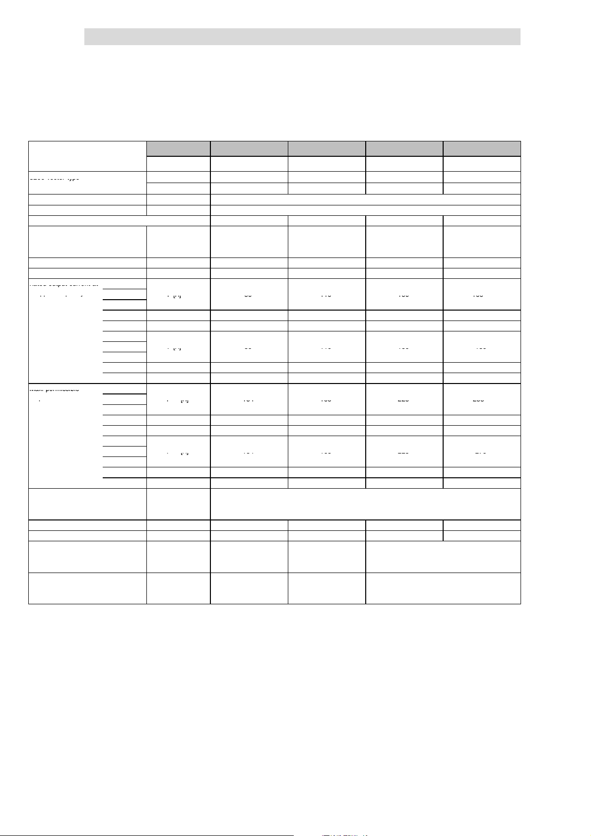
4
8200vectortyp
e
Ratedoutputcurrenta
t
ppq
y
Ir[A]8911015015
9
Ir[A]8911015018
0
Max.permissible
p
I
max
[A]134165225238
I
max
[A]134165225270
Show/Hide Bookmarks
Technical data
4.3
4.3.2
Typical motor power
Three-phaseAC asynchronous motor
(4 pole)
8200 vector type With mains filter E82EV453K4B3xx E82EV553K4B3xx E82EV753K4B3xx E82EV903K4B3xx
Mains voltage U
Alternative DC supply UDC[V] DC 450 V - 0 % ... 775 V + 0 %
Data for operation with 3/PE AC 400 V or DC 565 V
Rated mains current
without mains choke I
with mains choke I
Output power U, V, W Sr[kVA] 61.7 76.2 103.9 124.7
Output power +UG,-U
Rated output current at 1kHzsin
chopper frequency
Max. permissible 1kHzsin
output current for 60 s
at chopper frequency
Output voltage
Power loss (operation with Ir8) Pv[W] 1100 1470 1960 2400
Required mains choke Type ELN3-0038H085 ELN3-0027H105 ELN3-0022H130 ELN3-0017H170
Dimensions
Weight
2)
G
2kHzsin Ir[A]
4kHzsin
8kHzsin Ir[A] 59
16 kH z sin
1kHz
2kHz Ir[A]
4kHz
8kHz Ir[A] 89 110 150 171
16 k Hz
2kHzsin I
3)
4kHzsin
8kHzsin I
16 kH z sin
1kHz
2kHz I
4kHz
8kHz I
16 k Hz
without mains choke UM[V] 3~ 0 ... V
with mains choke UM[V] 3~ 0 ... approx. 94 % U
with mains filter H x W x D [mm] 510 x 340 x 375 591 x 340 x 375 680 x 450 x 375
without mains filter H x W x D [ mm] 510 x 340 x 285 591 x 340 x 285 680 x 450 x 285
with mains filter m[kg] 60 66 112
without mains filter m[kg] 34 37 59
4)
4)
4)
4)
Pr[kW] 45 55 75 90
Pr[hp] 60 75 100 120
Without mains filter E82EV453K4B2xx
[V] 3/PE AC 320 V - 0 % ... 550 V + 0 % ; 45 Hz - 0 % ... 65 Hz + 0 %
mains
[A] - - - -
mains
[A] 80.0 100 135 165
mains
PDC[kW] 5.1 0 28.1 40.8
5)
Ir[A] 46 60 67 72
5)
Ir[A] 54 77 105 108
[A] 134 165 225 238
max
[A] 88
max
I
[A] 69 78 87 94
max
[A] 134 165 225 270
max
[A] 134 165 225 221
max
I
[A] 81 100 136 140
max
Printed in bold = Data for operation at 8 kHz chopper frequency (Lenze setting)
1)
Operation only with mains choke or mains filter
2)
For operation with power-adapted motors additional power to be taken from the DC bus
3)
Currents for periodic load change: 1 min overcurrent with I
4)
Chopper frequency is reduced to 4 kHz if ϑ
5)
Possible for other types with different application conditions: Operation with increased rated output current and
the same load change
6)
Operation only with automatic chopper frequency reduction (C144 = 1). Ensure not to exceed the declared
currents.
89 110 150 159
6)
89 110 150 180
6)
(¶ 4.4-4)
Operation with rated power (normal operation)
Rated data for mains voltage 400 V
1)
E82EV553K4B2xx
76
114
max
1)
6)
6)
mains
max
reaches - 5 °C
E82EV753K4B2xx
92
138
/ 0 ... 650 Hz
/ 0 ... 650 Hz
mains
and 2 min basic load with 75 % I
1)
E82EV903K4B2xx
6)
6)
rx
100
150
6)
6)
6)
6)
1)
4.3-8
EDS 82EV903-1.0-11/2002
L
Page 67
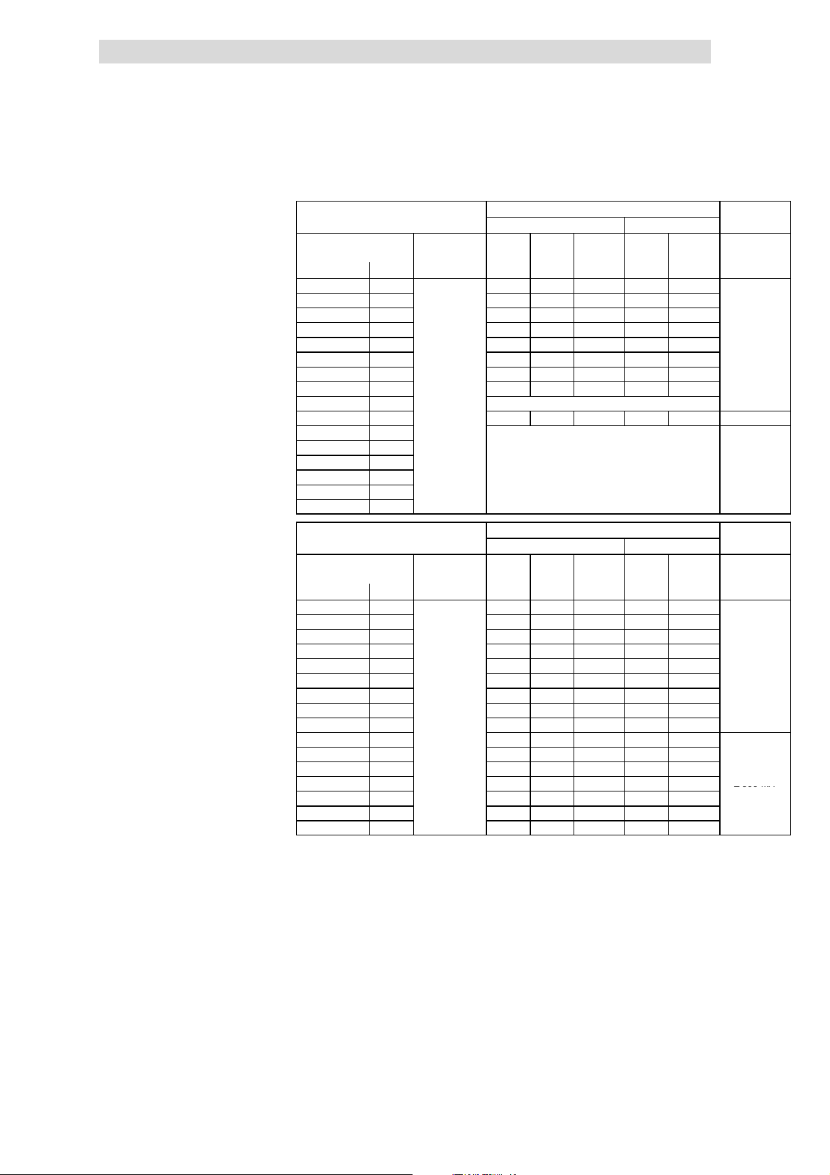
Technical data
A
2
)
3
)
3
0mA
3
)
A
2
)
3
)
3
0mA
3
)
≥
300mA
Show/Hide Bookmarks
4
Operation with rated power (normal operation)
Rated data for mains voltage 400 V
Fusesand cable cross-sections
(operation with rated power,
mains voltage 400V)
8200 vector mains L1, L2, L3,
Type [kW] [mm2] [AWG]
E82EV551K4C 0.55 M6 A B6 A 1 5A 18
E82EV751K4C 0.75 M6 A B6 A 1 5A 18
E82EV152K4C 1.5 M10 A B10 A 1.5 10 A 16
E82EV222K4C 2.2 M10 A B10 A 1.5 10 A 16
E82EV302K4C 3.0 M16 A B16 A 2.5 15 A 14
E82EV402K4C 4.0 M16 A B16 A 2.5 15 A 14
E82EV552K4C 5.5
E82EV752K4C 7.5
E82EV113K4C 11
E82EV153K4B 15
E82EV223K4B 22
E82EV303K4B 30
E82EV453K4B 45
E82EV553K4B 55
E82EV753K4B 75
E82EV903K4B 90
3/PE AC
320 ... 440V;
45 ... 65 Hz
4.3.2
Operation without mains choke
Installation to EN 60204-1 Installation to UL
PE
M25 A B25 A 4 20 A 12
M32 A B32 A 6
Operation only with mains choke
M63 A - 25 63 A 4 ≥ 300 mA
Operation only with mains choke
4)
L1, L2, L3,
25 A 10
1)
FI
PE
≥ 300 m
≥
4.3
Operation with mains choke
Installation to EN 60204-1 Installation to UL
8200 vector mains L1, L2, L3,
Type [kW] [mm2] [AWG]
E82EV551K4C 0.55 M6 A B6 A 1 5A 18
E82EV751K4C 0.75 M6 A B6 A 1 5A 18
E82EV152K4C 1.5 M10 A B10 A 1.5 10 A 16
E82EV222K4C 2.2 M10 A B10 A 1.5 10 A 16
E82EV302K4C 3.0 M10 A B10 A 1.5 10 A 16
E82EV402K4C 4.0 M16 A B16 A 2.5 15 A 14
E82EV552K4C 5.5
E82EV752K4C 7.5
E82EV113K4C 11
E82EV153K4B 15
E82EV223K4B 22 M50 A - 16 50 A 6
E82EV303K4B 30 M80 A - 25 80 A 3
E82EV453K4B 45 M100 A - 50 100 A 1 ≥ 300 mA
E82EV553K4B 55 M125 A - 50 125 A 0
E82EV753K4B 75 M160 A - 70 175 A 2/0
E82EV903K4B 90 M200 A - 95 200 A 3/0
Fuse
E.l.c.b.
1)
Use UL-approved cables, fuses and fuse holders only.
UL fuse: Voltage 500 ... 600 V, tripping characteristic ”H” or ”K5”
2)
All-current sensitive e.l.c.b. for use with E82EVxxxK4C0xx
3)
All-current sensitive e.l.c.b. for use with E82EVxxxK4C2xx
4)
Flexible cable can only be connected using pin end connectors.
Observe national and regional regulations (e. g. VDE 0113, EN 60204)
3/PE AC
320 ... 440V;
45 ... 65 Hz
M20 A B20 A 4 20 A 12
M20 A B20 A 4 20 A 12
M32 A B32 A 6
M35 A - 10 35 A 8
PE
4)
L1, L2, L3,
25 A 10
1)
FI
PE
≥ 300 m
≥
L
EDS 82EV903-1.0-11/2002
4.3-9
Page 68
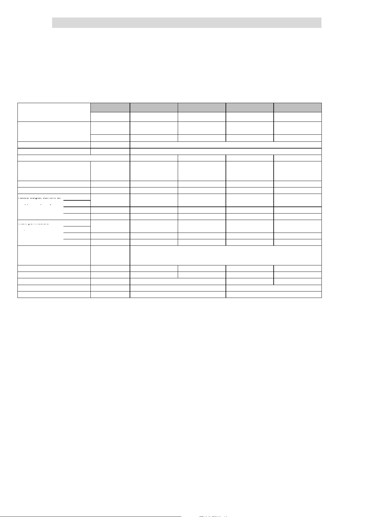
4
Ratedoutputcurrenta
t
ppq
y
Max.permissible
p
Show/Hide Bookmarks
Technical data
4.3
4.3.3
Operation with rated power (normal operation)
Rated data for mains voltage 500 V
4.3.3 Rated data for mains voltage 500 V
Typical motor power
Three-phaseAC asynchronous motor
(4 pole)
8200 vector type EMC filt er
Mains voltage U
Alternative DC supply UDC[V] DC 450 V - 0 % ... 775 V + 0 %
Data for operation with 3/PE AC 500 V or DC 710 V
Rated mains current
without mains choke I
with mains choke I
Output power U, V, W Sr[kVA] 1.3 1.7 2.7 3.9
Output power +UG,-U
Rated output current at 2kHzsin
chopper frequency
Max. permissible 2kHzsin
output current for 60 s
at chopper frequency
Output voltage
Power loss (operation with Ir8) Pv[W] 50 60 100 130
Required mains choke Type - - - Required brake resistor
Dimensions H x W x D [mm] 180 x 60 x 140 240 x 60 x 140
Weight m[kg] 1.2 1.6
2)
G
4kHzsin
8kHzsin Ir[A] 1.4 1.9 3.1 4.5
16 kH z sin
4kHzsin
3)
8kHzsin I
16 kH z sin
without mains choke UM[V] 3~ 0 ... V
with mains choke UM[V] 3~ 0 ... approx. 94 % U
6)
Pr[kW] 0.55 0.75 1.5 2.2
Pr[hp] 0.75 1.0 2.0 3.0
integrated
Without EMC filter E82EV551K4C2xx E82EV751K4C2xx E82EV152K4C2xx E82EV222K4C2xx
[V] 3/PE AC 320 V - 0 % ... 550 V + 0 % ; 45 Hz - 0 % ... 65 Hz + 0 %
mains
[A] 2.0 2.6 4.4 5.8
mains
[A] 1.4 1.8 3.1 4.1
mains
PDC[kW] 0.3 0.1 1.1 0.4
Ir[A] 1.4 1.9 3.1 4.5
4)
4)
Ir[A] 0.9
I
[A] 2.7 3.6 5.9 8.4
max
[A] 2.7 3.6 5.9 8.4
max
I
[A] 1.35
max
Type ERBM470R100W ERBM370R150W ERBM240R200W
Printed in bold = Data for operation at 8 kHz chopper frequency (Lenze setting)
2)
For operation with power-adapted motors additional power to be taken from the DC bus
3)
Currents for periodic load change: 1 min overcurrent with I
4)
Chopper frequency is reduced to 4 kHz if ϑ
5)
Maximum motor cable length 10 m!
6)
Operation at mains voltages 484 V - 0 % ... 550 V + 0 % is only permissible with brake resistor!
E82EV551K4C0xx
6)
E82EV751K4C0xx
5)
5)
1.2
1.85
reaches - 5 °C
max
6)
E82EV152K4C0xx
5)
5)
/ 0 ... 650 Hz
mains
and 2 min basic load with 75 % I
max
2.0 2.9
3.0 4.4
/ 0 ... 650 Hz
mains
6)
E82EV222K4C0xx
r
6)
4.3-10
EDS 82EV903-1.0-11/2002
L
Page 69
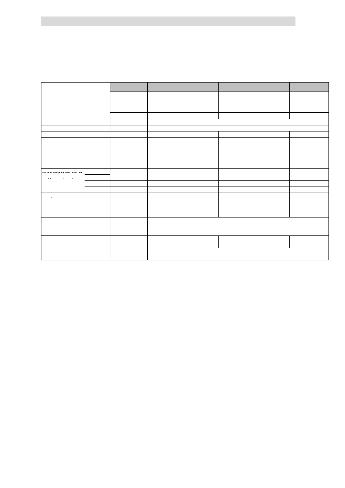
Technical data
Ratedoutputcurrenta
t
ppq
y
Max.permissible
p
Show/Hide Bookmarks
4
Operation with rated power (normal operation)
Rated data for mains voltage 500 V
Typical motor power
Three-phaseAC asynchronous motor
(4 pole)
8200 vector type EMC filt er
Mains voltage U
Alternative DC supply UDC[V] DC 450 V - 0 % ... 775 V + 0 %
Data for operation with 3/PE AC 500 V or DC 710 V
Rated mains current
without mains choke I
with mains choke I
Output power U, V, W Sr[kVA] 5.1 6.6 9.0 11.4 16.3
Output power +UG,-U
Rated output current at 2kHzsin
chopper frequency
Max. permissible 2kHzsin
output current for 60 s
at chopper frequency
Output voltage
Power loss (operation with Ir8) Pv[W] 145 180 230 300 410
Required mains choke Type - - - - ELN3-150H024
Dimensions H x W x D [mm] 240 x 100 x 140 240 x 125 x 140
Weight m[kg] 2.9 3.6
2)
G
4kHzsin
8kHzsin Ir[A] 5.8 7.6 10.4 13.2 18.8
16 kH z sin
4kHzsin
3)
8kHzsin I
16 kH z sin
without mains choke UM[V] 3~ 0 ... V
with mains choke UM[V] 3~ 0 ... approx. 94 % U
Pr[kW] 3.0 4.0 5.5 7.5 11
Pr[hp] 4.1 5.4 7.5 10.2 15
integrated
Without EMC filter E82EV302K4C2xx E82EV402K4C2xx E82EV552K4C2xx E82EV752K4C2xx E82EV113K4C2xx
mains
mains
mains
PDC[kW] 1.7 0.8 1.1 1.5 0
Ir[A] 5.8 7.6 10.4 13.2 18.8
4)
4)
Ir[A] 3.8 4.9 6.8 8.6 12.2
I
[A] 11.0 14.2 19.5 24.8 35.3
max
[A] 11.0 14.2 19.5 24.8 35.3
max
I
[A] 5.7 7.9 10.0 12.9 18.3
max
Printed in bold = Data for operation at 8 kHz chopper frequency (Lenze setting)
1)
2)
3)
4)
E82EV302K4C0xx E82EV402K4C0xx E82EV552K4C0xx E82EV752K4C0xx E82EV113K4C0xx
[V] 3/PE AC 320 V - 0 % ... 550 V + 0 % ; 45 Hz - 0 % ... 65Hz + 0 %
[A] 7.2 9.8 13.4 17.2 [A] 5.6 7.0 9.6 12.0 16.8
/ 0 ... 650 Hz
mains
Operation only with mains choke
For operation with power-adapted motors additional power to be taken from the DC bus
Currents for periodic load change: 1 min overcurrent with I
Chopper frequency is reduced to 4 kHz if ϑ
reaches - 5 °C
max
max
/ 0 ... 650 Hz
mains
and 2 min basic load with 75 % I
r
4.3.3
4.3
1)
1)
L
EDS 82EV903-1.0-11/2002
4.3-11
Page 70
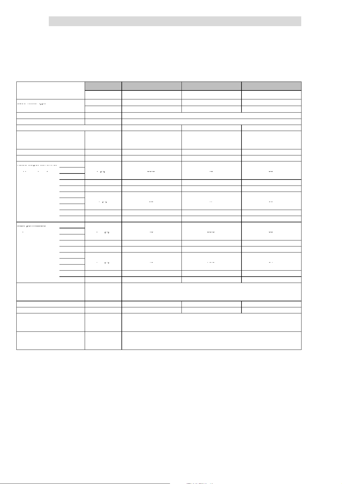
4
8200vectortyp
e
Ratedoutputcurrenta
t
ppq
y
Ir[A]30.54556
Ir[A]324756
Max.permissible
p
I
max
[A]4666.565
I
max
[A]4870.584
Show/Hide Bookmarks
Technical data
4.3
4.3.3
Typical motor power
Three-phaseAC asynchronous motor
(4 pole)
8200 vector type With mains filter E82EV153K4B3xx E82EV223K4B3xx E82EV303K4B3xx
Mains voltage U
Alternative DC supply UDC[V] DC 450 V - 0 % ... 775 V + 0 %
Data for operation with 3/PE AC 500 V or DC 710 V
Rated mains current
without mains choke/mains filter I
with mains choke/mains filter I
Output power U, V, W Sr[kVA] 26.6 39.1 49.9
Output power +UG,-U
Rated output current at 1kHzsin
chopper frequency
Max. permissible 1kHzsin
output current for 60 s
at chopper frequency
Output voltage
without mains choke/mains filter UM[V] 3~ 0 ... V
with mains choke/mains filter UM[V] 3~ 0 ... approx. 94 % U
Power loss (operation with Ir8) Pv[W] 430 640 810
Required mains choke Type - ELN3-0075H045 ELN3-0055H055
Dimensions
Weight
2)
G
2kHzsin Ir[A]
4kHzsin
8kHzsin Ir[A] 27 41 44
16 kH z sin
1kHz
2kHz Ir[A] 32 47 56
4kHz
8kHz Ir[A] 32 47 56
4)
16 k Hz
2kHzsin I
3)
4kHzsin
8kHzsin I
16 kH z sin
1kHz
2kHz I
4kHz
8kHz I
4)
16 k Hz
with mains filter H x W x D [mm] 350 x 250 x 340
without mains filter H x W x D [ mm] 350 x 250 x 250
with mains filter m[kg] 34
without mains filter m[kg] 15
Pr[kW] 18.5 30 37
Pr[hp] 25 40 49.5
Without mains filter E82EV153K4B2xx E82EV223K4B2xx
[V] 3/PE AC 320 V - 0 % ... 550 V + 0 % ; 45 Hz - 0 % ... 65 Hz + 0 %
mains
[A] 43.5 - -
mains
[A] 29.0 42.0 55.0
mains
PDC[kW] 11.8 4.6 0
5)
4)
4)
Ir[A] 19 28 30
Ir[A] 22 33 41
[A] 46 66.5 65
max
[A] 41 61 65
max
I
[A] 29 42 45
max
[A] 48 70.5 84
max
[A] 48 70.5 84
max
I
[A] 33 49 61
max
Printed in bold = Data for operation at 8 kHz chopper frequency (Lenze setting)
1)
Operation only with mains choke or mains filter
2)
For operation with power-adapted motors additional power to be taken from the DC bus
3)
Currents for periodic load change: 1 min overcurrent with I
4)
Chopper frequency is reduced to 4 kHz if ϑ
5)
Operation only with automatic chopper frequency reduction (C0144 = 1). Ensure not to exceed the declared
currents.
30.5 45 56
Operation with rated power (normal operation)
Rated data for mains voltage 500 V
reaches - 5 °C
max
1)
/ 0 ... 650 Hz
mains
max
/ 0 ... 650 Hz
mains
and 2 min basic load with 75 % I
E82EV303K4B2xx
5)
5)
r
1)
4.3-12
EDS 82EV903-1.0-11/2002
L
Page 71
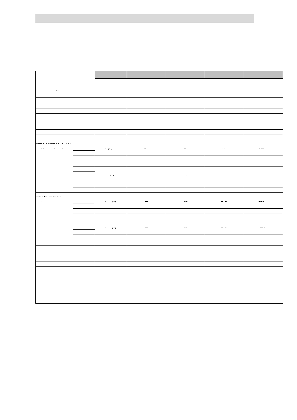
Technical data
8200vectortyp
e
Ratedoutputcurrenta
t
ppq
y
Ir[A]8410414114
9
Ir[A]8410514217
1
Max.permissible
p
I
max
[A]126156212223
I
max
[A]126157213256
Show/Hide Bookmarks
4
Operation with rated power (normal operation)
Rated data for mains voltage 500 V
Typical motor power
Three-phaseAC asynchronous motor
(4 pole)
8200 vector type With mains filter E82EV453K4B3xx E82EV553K4B3xx E82EV753K4B3xx E82EV903K4B3xx
Mains voltage U
Alternative DC supply UDC[V] DC 450 V - 0 % ... 775 V + 0 %
Data for operation with 3/PE AC 500 V or DC 710 V
Rated mains current
without mains choke/mains filter I
with mains choke/mains filter I
Output power U, V, W Sr[kVA] 73.9 91.4 124 149
Output power +UG,-U
Rated output current at 1kHzsin
chopper frequency
Max. permissible 1kHzsin
output current for 60 s
at chopper frequency
Output voltage
without mains choke/mains filter UM[V] 3~ 0 ... V
with mains choke/mains filter UM[V] 3~ 0 ... approx. 94 % U
Power loss (operation with Ir8) Pv[W] 1100 1470 1960 2400
Required mains choke Type ELN3-0038H085 ELN3-0027H105 ELN3-0022H130 ELN3-0017H170
Dimensions
Weight
2)
G
2kHzsin Ir[A]
4kHzsin
8kHzsin Ir[A] 55
16 kH z sin
1kHz
2kHz Ir[A] 84 105 142 171
4kHz
8kHz Ir[A] 84 105 142 162
4)
16 k Hz
2kHzsin I
3)
4kHzsin
8kHzsin I
16 kH z sin
1kHz
2kHz I
4kHz
8kHz I
4)
16 k Hz
with mains filter H x W x D [mm] 510 x 340 x 375 591 x 340 x 375 680 x 450 x 375
without mains filter H x W x D [ mm] 510 x 340 x 285 591 x 340 x 285 680 x 450 x 285
with mains filter m[kg] 60 66 112
without mains filter m[kg] 34 37 59
Pr[kW] 55 75 90 110
Pr[hp] 74 100 120 148
Without mains filter E82EV453K4B2xx
[V] 3/PE AC 320 V - 0 % ... 550 V + 0 % ; 45 Hz - 0 % ... 65 Hz + 0 %
mains
[A] - - - -
mains
[A] 80.0 100 135 165
mains
PDC[kW] 5.9 0 32.4 47.1
5)
4)
4)
Ir[A] 39 55 60 63
Ir[A] 58 72 98 99
[A] 126 156 212 223
max
[A] 82
max
I
[A] 63 72 78 83
max
[A] 126 157 213 256
max
[A] 126 157 213 211
max
I
[A] 75 94 128 130
max
Printed in bold = Data for operation at 8 kHz chopper frequency (Lenze setting)
1)
Operation only with mains choke or mains filter
2)
For operation with power-adapted motors additional power to be taken from the DC bus
3)
Currents for periodic load change: 1 min overcurrent with I
4)
Chopper frequency is reduced to 4 kHz if ϑ
5)
Operation only with automatic chopper frequency reduction (C0144 = 1). Ensure not to exceed the declared
currents.
1)
E82EV553K4B2xx
84 104 141 149
5)
5)
71
107
max
1)
5)
5)
mains
max
reaches - 5 °C
E82EV753K4B2xx
5)
86
5)
169
/ 0 ... 650 Hz
/ 0 ... 650 Hz
mains
and 2 min basic load with 75 % I
1)
E82EV903K4B2xx
r
94
141
4.3.3
5)
5)
5)
5)
4.3
1)
L
EDS 82EV903-1.0-11/2002
4.3-13
Page 72
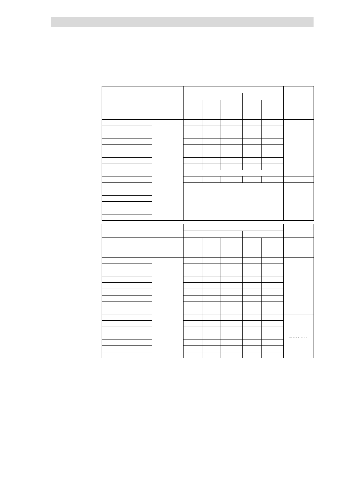
4
A
2
)
3
)
3
0mA
3
)
A
2
)
3
)
3
0mA
3
)
≥
300mA
Show/Hide Bookmarks
Technical data
4.3
4.3.3
Fusesand cable cross-sections
(operation with rated power,
mains voltage 500V)
Operation with rated power (normal operation)
Rated data for mains voltage 500 V
Operation without mains choke
Installation to EN 60204-1 Installation to UL
8200 vector mains L1, L2, L3,
Type [kW] [mm2] [AWG]
E82EV551K4C 0.55 M6 A B6 A 1 5A 18
E82EV751K4C 0.75 M6 A B6 A 1 5A 18
E82EV152K4C 1.5 M10 A B10 A 1.5 10 A 16
E82EV222K4C 2.2 M10 A B10 A 1.5 10 A 16
E82EV302K4C 3.0 M16 A B16 A 2.5 15 A 14
E82EV402K4C 4.0 M16 A B16 A 2.5 15 A 14
E82EV552K4C 5.5
E82EV752K4C 7.5
E82EV113K4C 11
E82EV153K4B 15
E82EV223K4B 22
E82EV303K4B 30
E82EV453K4B 45
E82EV553K4B 55
E82EV753K4B 75
E82EV903K4B 90
3/PE AC
320 ... 550V;
45 ... 65 Hz
M25 A B25 A 4 20 A 12
M32 A B32 A 6
Operation only with mains choke
M63 A - 25 63 A 4 ≥ 300 mA
Operation only with mains choke
PE
4)
L1, L2, L3,
PE
25 A 10
1)
FI
≥ 300 m
≥
Operation with mains choke
Installation to EN 60204-1 Installation to UL
8200 vector mains L1, L2, L3,
Type [kW] [mm2] [AWG]
E82EV551K4C 0.55 M6 A B6 A 1 5A 18
E82EV751K4C 0.75 M6 A B6 A 1 5A 18
E82EV152K4C 1.5 M10 A B10 A 1.5 10 A 16
E82EV222K4C 2.2 M10 A B10 A 1.5 10 A 16
E82EV302K4C 3.0 M10 A B10 A 1.5 10 A 16
E82EV402K4C 4.0 M16 A B16 A 2.5 15 A 14
E82EV552K4C 5.5
E82EV752K4C 7.5
E82EV113K4C 11
E82EV153K4B 15
E82EV223K4B 22 M50 A - 16 50 A 6
E82EV303K4B 30 M80 A - 25 80 A 3
E82EV453K4B 45 M100 A - 50 100 A 1 ≥ 300 mA
E82EV553K4B 55 M125 A - 50 125 A 0
E82EV753K4B 75 M160 A - 70 175 A 2/0
E82EV903K4B 90 M200 A - 95 200 A 3/0
Fuse
E.l.c.b.
1)
Use UL-approved cables, fuses and fuse holders only.
UL fuse: Voltage 500 ... 600 V, tripping characteristic ”H” or ”K5”
2)
All-current sensitive e.l.c.b. for use with E82EVxxxK4C0xx
3)
All-current sensitive e.l.c.b. for use with E82EVxxxK4C2xx
4)
Flexible cable can only be connected using pin end connectors.
Observe national and regional regulations (e. g. VDE 0113, EN 60204)
3/PE AC
320 ... 550V;
45 ... 65 Hz
M20 A B20 A 4 20 A 12
M20 A B20 A 4 20 A 12
M32 A B32 A 6
M35 A - 10 35 A 8
PE
4)
L1, L2, L3,
25 A 10
1)
FI
PE
≥ 300 m
≥
4.3-14
EDS 82EV903-1.0-11/2002
L
Page 73
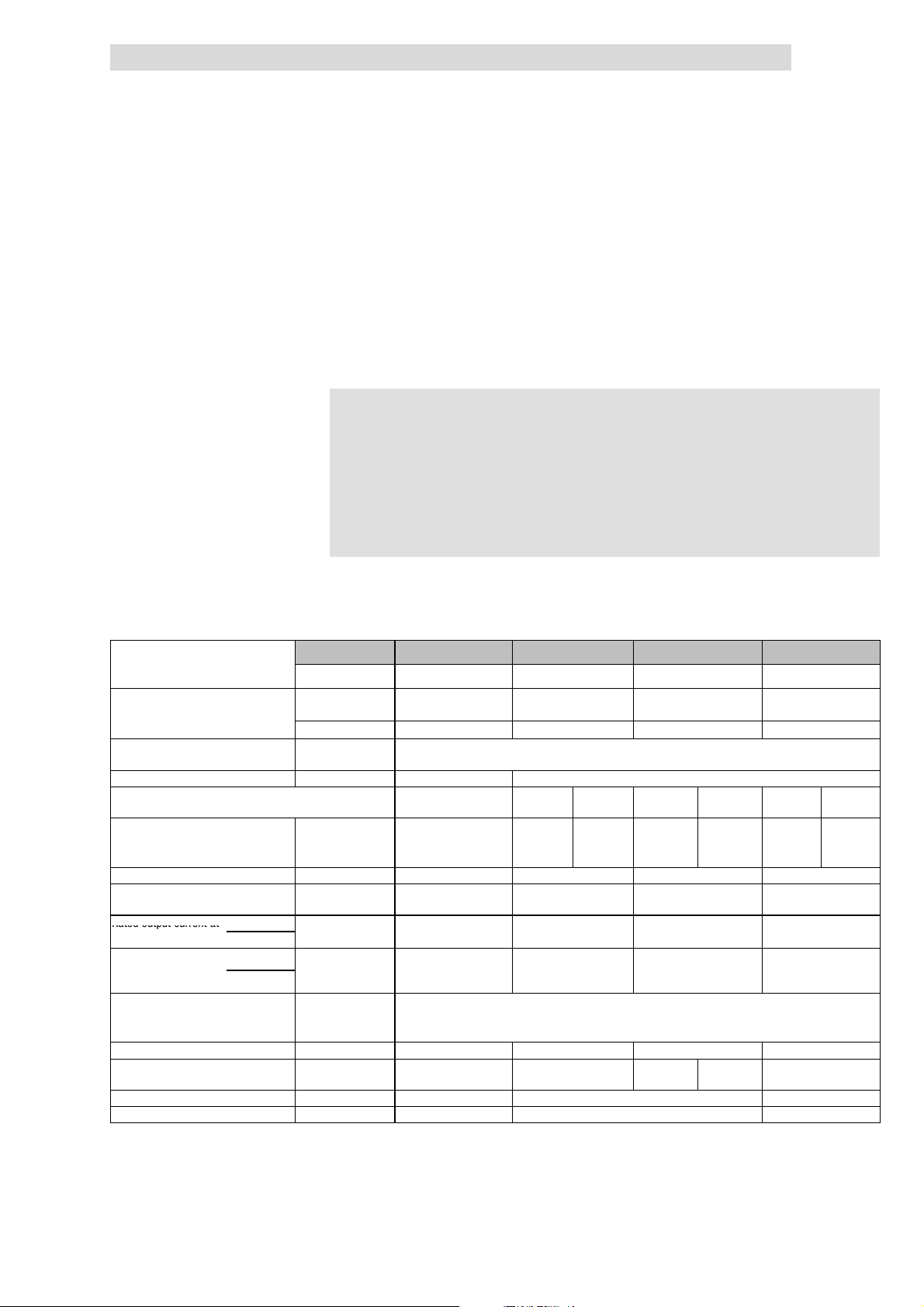
Technical data
Ratedoutputcurrenta
t
Show/Hide Bookmarks
4
Operation with increased rated power
Rated data for mains voltage 230 V
4.4 Operation with increased rated power
Under the application conditions described here the controller can be operated
in continuous operation with a motor of higher performance. The overload
capacityis reduced to120 %.
Typical applications are pumps with square-law load characteristic or blowers.
)
) Note!
))
Operation with increased rated power is only permissible
l with the drive controllers mentioned
l within the mains voltage range mentioned
l with the chopper frequency mentioned
l with the prescribed fuses, cable cross-sections and mains
chokes
4.4
4.4.1
4.4.1 Rated data for mains voltage 230 V
Maximum motor power
Three-phaseAC asynchronous motor
(4 pole)
8200 vector type EMC filt er
Mains voltage V
Alternative DC supply UDC[V] not possible DC 140 V - 0 % ... 370 V + 0 %
Data for operation with 1/N/PE (3 PE) AC 230 V or DC
325 V
Rated mains current
without mains choke I
with mains choke I
Output power U, V, W Sr[kVA] 0.8 1.4 1.9 3.3
Output power +UG,-U
Rated output current at 2kHzsin
chopper frequency
Max. permissible
output current for 60 s
at chopper frequency
Output voltage
Power loss (operation with I
Required mains choke Type - ELN1-0500H005 ELN1-0500H009 E82ZL75132B -
2)
G
4kHzsin
2kHzsin
4kHzsin
3)
without mains choke UM[V] 3~ 0 ... V
with mains choke UM[V] 3~ 0 ... approx. 94 % V
) Pv[W] 30 50 60 100
N24
Pr[kW] 0.37 0.75 1.1 2.2
Pr[hp] 0.5 1.0 1.5 3.0
integrated
Without EMC filter E82EV251K2C2xx E82EV551K2C2xx
[V] 1/N/PE AC 180 V - 0 % ... 264 V + 0 % ; 45 Hz - 0 % ... 65 Hz + 0 %
mains
[A] 4.1 - - - - 18.0 10.4
mains
[A] 3.6 6.7 3.3 9.0 4.4 15.0 7.6
mains
PDC[kW] DC bus operation not
Ir[A] 2.0 3.6 4.8 8.4
I
[A] 2.5 4.5 6.0 10.5
max
E82EV251K2C0xx E82EV551K2C0xx
3/PE AC 100 V - 0 % ... 264 V + 0 % ; 45 H z - 0 % ... 65 Hz + 0 %
1/N/PE 1/N/PE 3/PE 1/N/PE 3/PE 1/N/PE 3/PE
0.1 0 0.4
possible
1)
1)
mains
/ 0 ... 650 Hz
E82EV751K2C0xx
E82EV751K2C2xx
/ 0 ... 650 Hz
mains
1)
1)
E82EV152K2C0xx
E82EV152K2C2xx
Dimensions H x W x D [mm] 120 x 60 x 140 180 x 60 x 140 240 x 60 x 140
Weight m[kg] 0.8 1.2 1.6
L
1)
Operation only with mains choke
2)
For operation with power-adapted motors additional power to be taken from the DC bus
3)
Currents for periodic load change: 1 min overcurrent with I
EDS 82EV903-1.0-11/2002
and 2 min basic load with 75 % I
max
r
4.4-1
Page 74
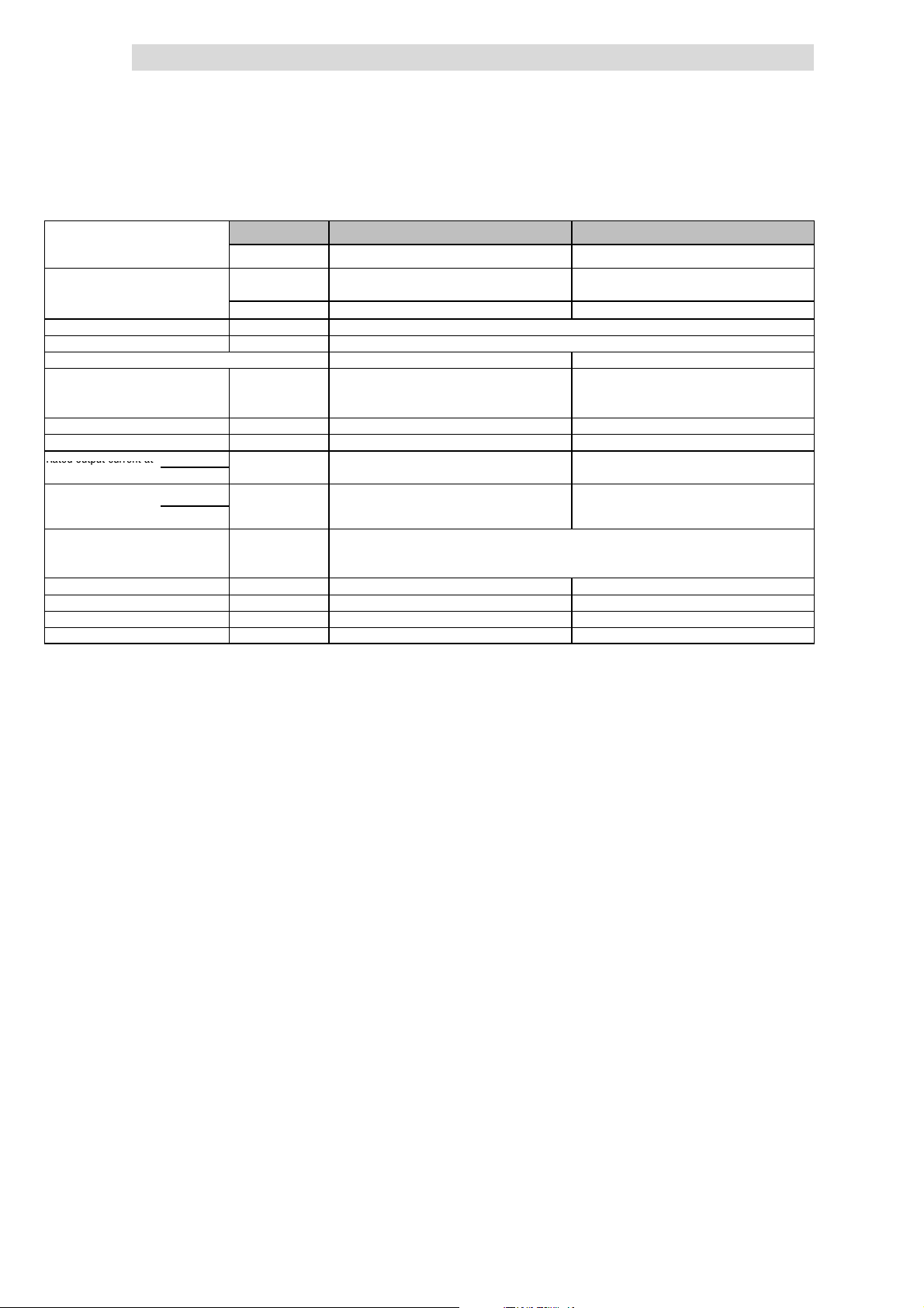
4
Ratedoutputcurrenta
t
Show/Hide Bookmarks
Technical data
4.4
4.4.1
Maximum motor power
Three-phaseAC asynchronous motor
(4 pole)
8200 vector type EMC filt er
Mains voltage V
Alternative DC supply VDC[V] DC 140 V - 0 % ... 370 V + 0 %
Data for operation with 3/PE AC 230 V or DC 325 V
Rated mains current
without mains choke I
with mains choke I
Output power U, V, W Sr[kVA] 5.7 10.8
Output power +UG,-U
Rated output current at 2kHzsin
chopper frequency
Max. permissible
output current for 60 s
at chopper frequency
Output voltage
Power loss (operation with I
Required mains choke Type - ELN3-088H035
Dimensions H x W x D [mm] 240 x 100 x 140 240 x 125 x 140
Weight m[kg] 2.9 3.6
2)
G
4kHzsin
2kHzsin
4kHzsin
3)
without mains choke UM[V] 3~ 0 ... V
with mains choke UM[V] 3~ 0 ... approx. 94 % V
) Pv[W] 150 250
N24
Pr[kW] 4.0 7.5
Pr[hp] 5.4 10.2
integrated
Without EMC filter E82EV302K2C2xx E82EV552K2C2xx
[V] 3/PE AC 100 V - 0 % ... 264 V + 0 % ; 45 Hz - 0 % ... 65 Hz + 0 %
mains
[A] 18.7 -
mains
[A] 14.4 25.2
mains
PDC[kW] 0 0
Ir[A] 14.4 27.0
I
[A] 18.0 33.8
max
1)
Operation only with mains choke
2)
For operation with power-adapted motors additional power to be taken from the DC bus
3)
Currents for periodic load change: 1 min overcurrent with I
E82EV302K2C0xx E82EV552K2C0xx
Operation with increased rated power
Rated data for mains voltage 230 V
/ 0 ... 650 Hz
mains
max
/ 0 ... 650 Hz
mains
and 2 min basic load with 75 % I
1)
1)
r
4.4-2
EDS 82EV903-1.0-11/2002
L
Page 75
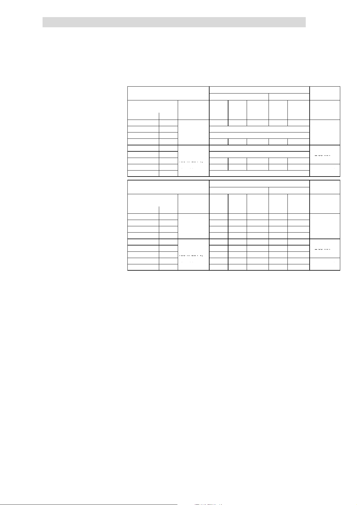
Technical data
A
2
)
3/PEA
C
≥
30m
A
100...264V;
A
565
≥
300mA
)
A
2
)
3/PEA
C
≥
30m
A
100...264V;
A
565
≥
300mA
)
Show/Hide Bookmarks
4
Operation with increased rated power
Rated data for mains voltage 230 V
Fusesand cable cross-sections
(operation with increasesrated
power, mains voltage 230 V)
8200 vector Mains L1, L2, L3,
Type [kW] [mm2] [AWG]
E82EV251K2C 0.25
E82EV551K2C 0.55
E82EV751K2C 0.75
E82EV152K2C 1.5
E82EV551K2C 0.55 Operation only with mains choke
E82EV751K2C 0.75
E82EV152K2C 1.5
E82EV302K2C 3.0
E82EV552K2C 5.5
8200 vector Mains L1, L2, L3,
Type [kW] [mm2] [AWG]
E82EV251K2C 0.25
E82EV551K2C 0.55
E82EV751K2C 0.75
E82EV152K2C 1.5
E82EV551K2C 0.55 M6 A B6 A 1 5A 18
E82EV751K2C 0.75
E82EV152K2C 1.5
E82EV302K2C 3.0
E82EV552K2C 5.5
Fuse
E.l.c.b.
1)
Use UL-approved cables, fuses and fuse holders only.
UL fuse: voltage 240 V, tripping characteristic ”H” or ”K5”
2)
Pulse-current or universal-current sensitive earth leakage circuit breaker
3)
All-current sensitive e.l.c.b.
4)
All-current sensitive e.l.c.b. for use with E82EVxxxK2C0xx
5)
All-current sensitive e.l.c.b. for use with E82EVxxxK2C2xx
6)
Flexible cable can only be connected using pin end connectors.
Observe national and regional regulations (e. g. VDE 0113, EN 60204)
Operation without mains choke
Installation to EN 60204-1 Installation to UL
PE
1/N/PE AC
180 ... 264V;
45 ... 65 Hz
3/PEAC
100 ... 264 V; M16 A B16 A 2.5 15 A 14
45 ... 65 Hz
1/N/PE AC
180 ... 264V;
45 ... 65 Hz
3/PEAC
100 ... 264 V; M10 A B10 A 1.5 10 A 16
45 ... 65 Hz
M10 A C10 A 1.5 10 A 16
Operation only with mains choke
Operation only with mains choke
M20 A B20 A 2x1.5 20 A 2x16
Operation only with mains choke ≥ 30 mA
M25 A B25 A 4 25 A 10
Operation only with mains choke
Operation with mains choke
Installation to EN 60204-1 Installation to UL
PE
M10 A C10 A 1.5 10 A 16
M10 A B10 A 1.5 10 A 16
M10 A B10 A 1.5 10 A 16
M16 A B16 A 2x1.5 15 A 2x16
M10 A B10 A 1.5 10 A 16 ≥ 30 mA
M20 A B20 A 4 20 A 12
M32 A B32 A 6
6)
L1, L2, L3,
L1, L2, L3,
35 A 8
4.4
4.4.1
1)
PE
1)
PE
FI
≥ 30 m
≥ 300 m
≥ 30 mA
FI
≥ 30 m
≥ 300 m
≥ 30 mA
3)
4)
5)
3)
4)
5)
L
EDS 82EV903-1.0-11/2002
4.4-3
Page 76
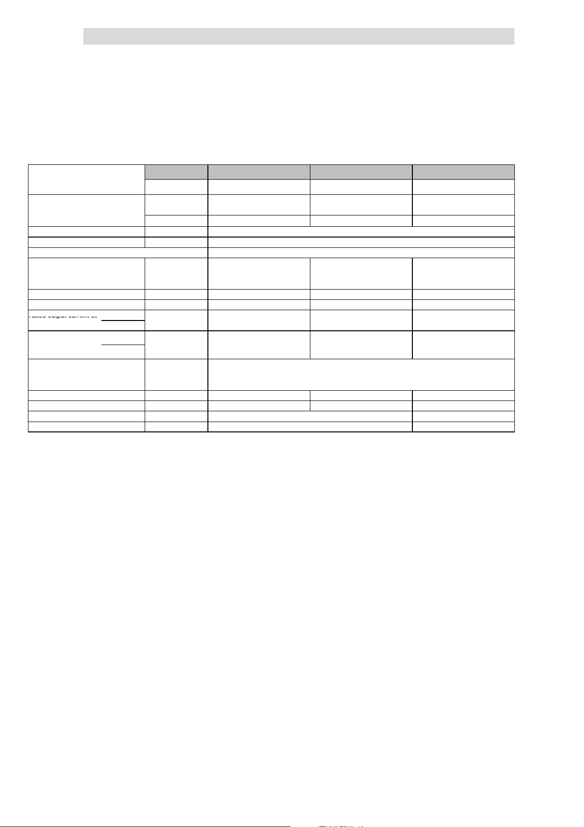
4
Ratedoutputcurrenta
t
Show/Hide Bookmarks
Technical data
4.4
4.4.2
Operation with increased rated power
Rated data for mains voltage 400 V
4.4.2 Rated data for mains voltage 400 V
Maximum motor power
Three-phaseAC asynchronous motor
(4 pole)
8200 vector type EMC filt er
Mains voltage V
Alternative DC supply VDC[V] DC 450 V - 0 % ... 625 V + 0 %
Data for operation with 3/PE AC 400 V or DC 565 V
Rated mains current
without mains choke I
with mains choke I
Output power U, V, W Sr[kVA] 1.5 2.0 4.6
Output power +UG,-U
Rated output current at 2kHzsin
chopper frequency
Max. permissible
output current for 60 s
at chopper frequency
Output voltage
Power loss (operation with Ir8) Pv[W] 50 60 130
Required mains choke Type - EZN3A1500H003 E82ZL22234B
Dimensions H x W x D [mm] 180 x 60 x 140 240 x 60 x 140
Weight m[kg] 1.2 1.6
2)
G
4kHzsin
2kHzsin
4kHzsin
3)
without mains choke UM[V] 3~ 0 ... V
with mains choke UM[V] 3~ 0 ...approx. 94 % V
Pr[kW] 0.75 1.1 3.0
Pr[hp] 1.0 1.5 4.0
integrated
Without EMC filter E82EV551K4C2xx E82EV751K4C2xx
[V] 3/PE AC 320 V - 0 % ... 440 V + 0 % ; 45 Hz - 0 % ... 65 Hz + 0 %
mains
[A] 2.9 - -
mains
[A] 2.4 2.8 6.1
mains
PDC[kW] 0.1 0 0
Ir[A] 2.2 2.9 6.7
I
[A] 2.7 3.6 8.4
max
1)
Operation only with mains choke
2)
For operation with power-adapted motors additional power to be taken from the DC bus
3)
Currents for periodic load change: 1 min overcurrent with I
E82EV551K4C0xx E82EV751K4C0xx
mains
max
1)
1)
/ 0 ... 650 Hz
/ 0 ... 650 Hz
mains
and 2 min basic load with 75 % I
E82EV222K4C0xx
E82EV222K4C2xx
r
1)
1)
4.4-4
EDS 82EV903-1.0-11/2002
L
Page 77
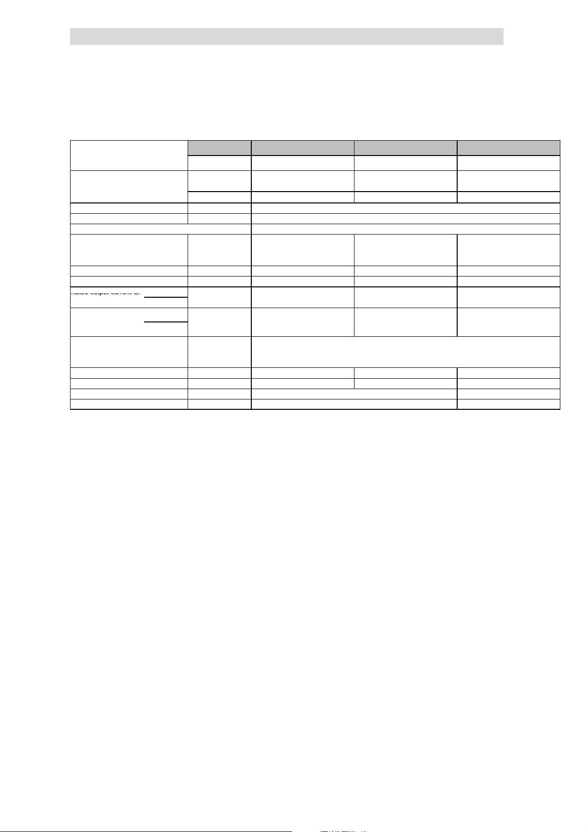
Technical data
Ratedoutputcurrenta
t
Show/Hide Bookmarks
4
Operation with increased rated power
Rated data for mains voltage 400 V
Maximum motor power
Three-phaseAC asynchronous motor
(4 pole)
8200 vector type EMC filt er
Mains voltage V
Alternative DC supply VDC[V] DC 450 V - 0 % ... 625 V + 0 %
Data for operation with 3/PE AC 400 V or DC 565 V
Rated mains current
without mains choke I
with mains choke I
Output power U, V, W Sr[kVA] 6.0 7.9 13.7
Output power +UG,-U
Rated output current at 2kHzsin
chopper frequency
Max. permissible
output current for 60 s
at chopper frequency
Output voltage
Power loss (operation with Ir8) Pv[W] 145 180 300
Required mains choke Type - EZN3A0300H013 ELN3-0150H024
Dimensions H x W x D [mm] 240 x 100 140 240 x 125 x 140
Weight m[kg] 2.9 3.6
2)
G
4kHzsin
2kHzsin
4kHzsin
3)
without mains choke UM[V] 3~ 0 ... V
with mains choke UM[V] 3~ 0 ...approx. 94 % V
Pr[kW] 4.0 5.5 11
Pr[hp] 5.4 7.5 15
integrated
Without EMC filter E82EV302K4C2xx E82EV402K4C2xx
[V] 3/PE AC 320 V - 0 % ... 440 V + 0 % ; 45 Hz - 0 % ... 65 Hz + 0 %
mains
[A] 10.8 - -
mains
[A] 8.4 10.6 18.0
mains
PDC[kW] 0.7 0 0
Ir[A] 8.7 11.4 19.8
I
[A] 11.0 14.2 24.8
max
1)
Operation only with mains choke
2)
For operation with power-adapted motors additional power to be taken from the DC bus
3)
Currents for periodic load change: 1 min overcurrent with I
E82EV302K4C0xx E82EV402K4C0xx
mains
max
1)
1)
/ 0 ... 650 Hz
/ 0 ... 650 Hz
mains
and 2 min basic load with 75 % I
E82EV752K4C0xx
E82EV752K4C2xx
r
4.4
4.4.2
1)
1)
L
EDS 82EV903-1.0-11/2002
4.4-5
Page 78
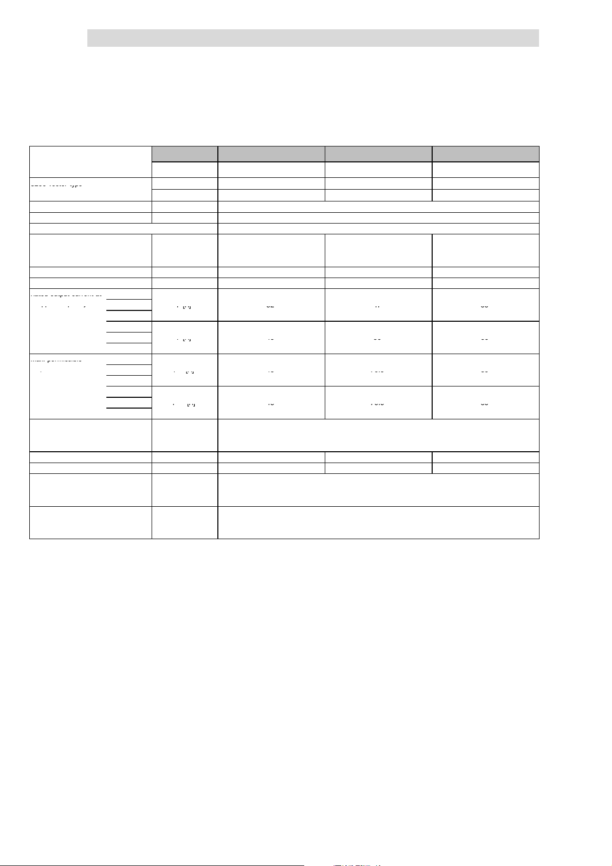
4
8200vectortyp
e
Ratedoutputcurrenta
t
ppq
y
Ir[A]324759
Ir[A]435666
Max.permissible
p
I
max
[A]4870.589
I
max
[A]4870.589
Show/Hide Bookmarks
Technical data
4.4
4.4.2
Maximum motor power
Three-phaseAC asynchronous motor
(4 pole)
8200 vector type With mains filter E82EV153K4B3xx E82EV223K4B3xx -
Mains voltage U
Alternative DC supply UDC[V] DC 450 V - 0 % ... 625 V + 0 %
Data for operation with 3/PE AC 400 V or DC 565 V
Rated mains current
without mains choke/mains filter I
with mains chokde/mains filter I
Output power U, V, W SN4[kVA] 29.8 39.5 46.4
Output power +UG,-U
Rated output current at 1kHzsin
chopper frequency
Max. permissible 1kHzsin
output current for 60 s
at chopper frequency
Output voltage
without mains choke/mains filter UM[V] 3~ 0 ... V
with mains chokde/mains filter UM[V] 3~ 0 ... approx. 94 % V
Power loss (operation with Ir8) Pv[W] 430 640 810
Required mains choke type] ELN3-0075H045 ELN3-0055H055 ELN3-0055H055
Dimensions
Weight
2)
G
2kHzsin Ir[A] 32 47 59
4kHzsin
1kHz
2kHz Ir[A] 43 56 66
4kHz
2kHzsin I
3)
4kHzsin
1kHz
2kHz I
4kHz
with mains filter H x W x D [mm] 350 x 250 x 340
without mains filter H x W x D [ mm] 350 x 250 x 250
with mains filter m[kg] 34
without mains filter m[kg] 15
Pr[kW] 22 30 37
Pr[hp] 30 40 50
Without mains filter E82EV153K4B2xx
[V] 3/PE AC 320 V - 0 % ... 440 V + 0 % ; 45 Hz - 0 % ... 65 Hz + 0 %
mains
[A] - - -
mains
[A] 39.0 50.0 60.0
mains
PDC[kW] 10.2 4.0 0
[A] 48 70.5 89
max
[A] 48 70.5 89
max
1)
Operation only with mains choke or mains filter
2)
For operation with power-adapted motors additional power to be taken from the DC bus
3)
Currents for periodic load change: 1 min overcurrent with I
4)
Maximum permissible ambient operating temperature +35 °C
1)
Operation with increased rated power
Rated data for mains voltage 400 V
E82EV223K4B2xx
mains
max
1)
/ 0 ... 650 Hz
/ 0 ... 650 Hz
mains
and 2 min basic load with 75 % I
E82EV303K4B2xx
r
1) 4)
4.4-6
EDS 82EV903-1.0-11/2002
L
Page 79
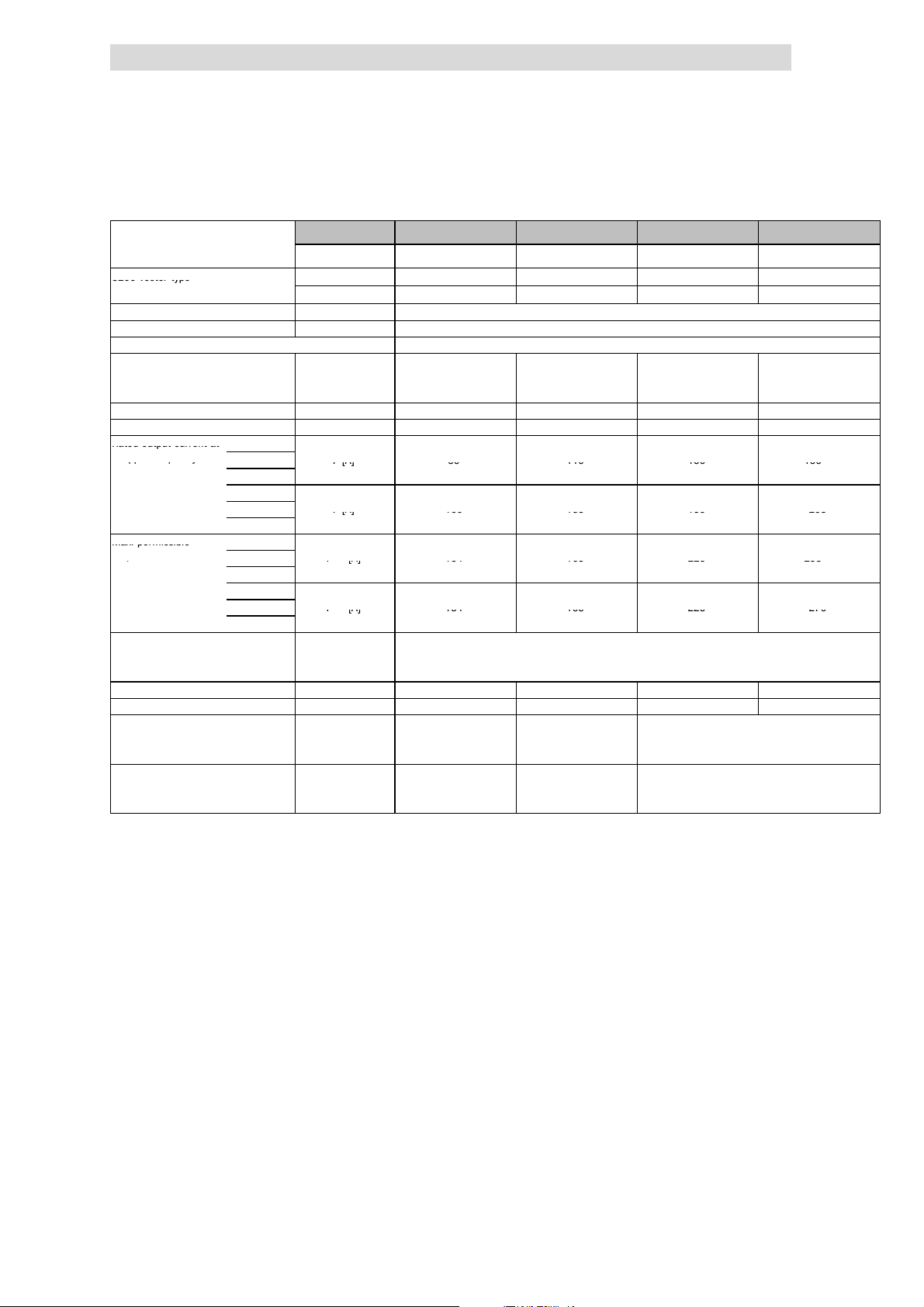
Technical data
8200vectortyp
e
Ratedoutputcurrenta
t
ppq
y
Ir[A]8911015015
9
Ir[A]100135159205
Max.permissible
p
I
max
[A]134165225238
I
max
[A]134165225270
Show/Hide Bookmarks
4
Operation with increased rated power
Rated data for mains voltage 400 V
Typical motor power
Three-phaseAC asynchronous motor
(4 pole)
8200 vector type With mains filter - E82EV553K4B3xx
Mains voltage V
Alternative DC supply UDC[V] DC 450 V - 0 % ... 625 V + 0 %
Data for operation with 3/PE AC 400 V or DC 565 V
Rated mains current
without mains choke/mains filter I
with mains chokde/mains filter I
Output power U, V, W Sr8[kVA] 74.8 91.5 110 142
Output power +UG,-U
Rated output current at 1kHzsin
chopper frequency
Max. permissible 1kHzsin
output current for 60 s
at chopper frequency
Output voltage
without mains choke/mains filter UM[V] 3~ 0 ... V
with mains chokde/mains filter UM[V] 3~ 0 ... approx. 94 % v
Power loss (operation with Ir8) Pv[W] 1100 1470 1960 2400
Required mains choke Type ELN3-0027H105 ELN3-0022H130 ELN3-0017H170 ELN3-0014H200
Dimensions
Weight
2)
G
2kHzsin Ir[A] 89 110 150 159
4kHzsin
1kHz
2kHz Ir[A] 100 135 159 205
4kHz
2kHzsin I
3)
4kHzsin
1kHz
2kHz I
4kHz
with mains filter H x W x D [mm] 510 x 340 x 375 591 x 340 x 375 680 x 450 x 375
without mains filter H x W x D [ mm] 510 x 340 x 285 591 x 340 x 285 680 x 450 x 285
with mains filter m[kg] 60 66 112
without mains filter m[kg] 34 37 59
Pr[kW] 55 75 90 110
Pr[hp] 75 100 120 148
4)
Without mains filter E82EV453K4B2xx1)E82EV553K4B2xx
[V] 3/PE AC 320 V - 0 % ... 440 V + 0 % ; 45 Hz - 0 % ... 65 Hz + 0 %
mains
[A] - - - -
mains
[A] 97.0 119 144 185
mains
PDC[kW] 5.1 0 28.1 40.8
[A] 134 165 225 238
max
[A] 134 165 225 270
max
1)
Operation only with mains choke or mains filter
2)
For operation with power-adapted motors additional power to be taken from the DC bus
3)
Currents for periodic load change: 1 min overcurrent with I
4)
Maximum permissible ambient operating temperature +35 °C
5)
Operation only with automatic chopper frequency reduction (C144 = 1). Ensure not to exceed the declared
currents.
1) 4)
/ 0 ... 650 Hz
mains
mains
and 2 min basic load with 75 % I
max
- -
E82EV753K4B2xx1)E82EV903K4B2xx
/ 0 ... 650 Hz
5)
5)
r
4.4
4.4.2
1) 4)
L
EDS 82EV903-1.0-11/2002
4.4-7
Page 80
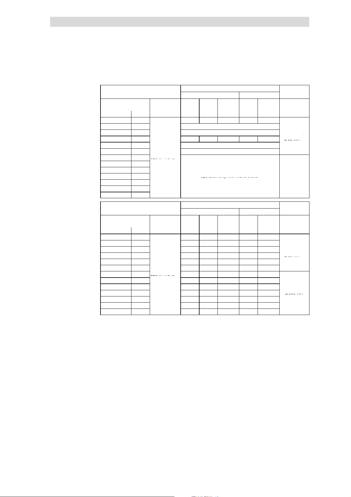
4
A
≥
300mA
)
≥
30m
A
3/PEA
C
320...440V;
565
Operationonlywithmainschoke
A
≥
300mA
)
≥
30m
A
3/PEA
C
320...440V;
45...65Hz
≥
300mA
Show/Hide Bookmarks
Technical data
4.4
4.4.2
Fusesand cable cross-sections
(operation with increased rated
power, mains voltage 400 V)
Operation with increased rated power
Rated data for mains voltage 400 V
Operation without mains choke
Installation to EN 60204-1 Installation to UL
8200 vector Mains L1, L2, L3,
Type [kW] [mm2] [AWG]
E82EV551K4C 0.55 M6 A B6 A 1 5A 18
E82EV751K4C 0.75 Operation only with mains choke
E82EV222K4C 2.2 Operation only with mains choke
E82EV302K4C 3.0 M16 A B16 A 2.5 15 A 14
E82EV402K4C 4.0 Operation only with mains choke
E82EV752K4C 7.5
E82EV153K4B 15
E82EV223K4B 22
E82EV303K4B 30
E82EV453K4B 45 Operation only with mains choke
E82EV553K4B 55
E82EV753K4B 75
E82EV903K4B 90
8200 vector Mains L1, L2, L3,
Type [kW] [mm2] [AWG]
E82EV551K4C 0.55 M6 A B6 A 1 5A 18
E82EV751K4C 0.75 M6 A B6 A 1 5A 18
E82EV222K4C 2.2 M10 A B10 A 1.5 10 A 16
E82EV302K4C 3.0 M10 A B10 A 1.5 10 A 16
E82EV402K4C 4.0 M16 A B16 A 2.5 15 A 14
E82EV752K4C 7.5
E82EV153K4B 15
E82EV223K4B 22
E82EV303K4B 30
E82EV453K4B 45 M125 A - 50 125 A 0 ≥ 300 mA
E82EV553K4B 55 M160 A - 70 175 A 2/0
E82EV753K4B 75 M160 A - 70 175 A 2/0
E82EV903K4B 90 M200 A - 95 200 A 3/0
Fuse
E.l.c.b.
1)
Use UL-approved cables, fuses and fuse holders only.
UL fuse: Voltage 500 ... 600 V, tripping characteristic ”H” or ”K5”
2)
All-current sensitive e.l.c.b. for use with E82EVxxxK4C0xx
3)
All-current sensitive e.l.c.b. for use with E82EVxxxK4C2xx
Observe national and regional regulations (e. g. VDE 0113, EN 60204)
3/PEAC
320 ... 440 V;
45 ... 65 Hz
3/PEAC
320 ... 440 V; M50 A - 16 50 A 6
45 ... 65 Hz
Operation only with mains choke
Operation with mains choke
Installation to EN 60204-1 Installation to UL
M25 A B25 A 4 25 A 10
M63 A - 25 63 A 4
M80 A - 25 80 A 3
PE
PE
L1, L2, L3,
L1, L2, L3,
1)
FI
PE
≥ 300 m
≥ 30 mA
1)
FI
PE
≥ 300 m
≥ 30 mA
2)
3)
2)
3)
4.4-8
EDS 82EV903-1.0-11/2002
L
Page 81

Technical data
Show/Hide Bookmarks
4
Operation with increased rated power
Mains voltage 500 V
4.4.3 Mains voltage 500 V
The operation with increased rated power is not possible for 500 V rated mains
voltage.
4.4
4.4.3
L
EDS 82EV903-1.0-11/2002
4.4-9
Page 82

Show/Hide Bookmarks
Page 83

Basic device installation
Show/Hide Bookmarks
5
Contents
5 Basic device installation
5.1 Contents
5.1 Contents 5.1-1................................................................
5.2 Important notes 5.2-1...........................................................
5.3 Basic units in the power range 0.25 ... 2.2 kW 5.3-1....................................
5.3.1 Mounting with fixing rails (standard) 5.3-1...................................
5.3.2 Thermally separated mounting (push-through technique) 5.3-2....................
5.3.3 Mounting in ”cold plate” technique 5.3-6....................................
5.3.4 DIN rail mounting 5.3-8................................................
5.3.5 Lateral mounting 5.3-9.................................................
5.4 Basic units in the power range 3 ... 11 kW 5.4-1.......................................
5.4.1 Mounting with fixing rails (standard) 5.4-1...................................
5.4.2 Thermally separated mounting (push-through technique) 5.4-2....................
5.4.3 Mounting in ”cold plate” technique 5.4-4....................................
5.4.4 Lateral mounting 5.4-6.................................................
5.1
5.5 Basic units in the power range 15 ... 30 kW 5.5-1......................................
5.5.1 Mounting with fixing brackets and mains choke (standard) 5.5-1..................
5.5.2 Mounting with fixing brackets and footprint mains filter 5.5-2.....................
5.5.3 Mounting with fixing brackets and built-on mains filter 5.5-3.....................
5.5.4 Thermally separated mounting (push-through technique) 5.5-4....................
5.5.5 Mounting in ”cold plate” technique 5.5-5....................................
5.6 Basic units in the power range 45 ... 55 kW 5.6-1......................................
5.6.1 Mounting with fixing brackets and mains choke (standard) 5.6-1..................
5.6.2 Mounting with fixing brackets and footprint mains filter 5.6-2.....................
5.6.3 Mounting with fixing brackets and built-on mains filter 5.6-3.....................
5.6.4 Thermally separated mounting (push-through technique) 5.6-4....................
5.7 Basic units in the power range 75 ... 90 kW 5.7-1......................................
5.7.1 Mounting with fixing brackets and mains choke (standard) 5.7-1..................
5.7.2 Mounting with fixing brackets and footprint mains filter 5.7-2.....................
5.7.3 Mounting with fixing brackets and built-on mains filter (mounting variant 1) 5.7-3.....
5.7.4 Mounting with fixing brackets and built-on mains filter (mounting variant 2) 5.7-4......
5.7.5 Thermally separated mounting (push-through technique) 5.7-5....................
L
EDS 82EV903-1.0-11/2002
5.1-1
Page 84

Show/Hide Bookmarks
Page 85
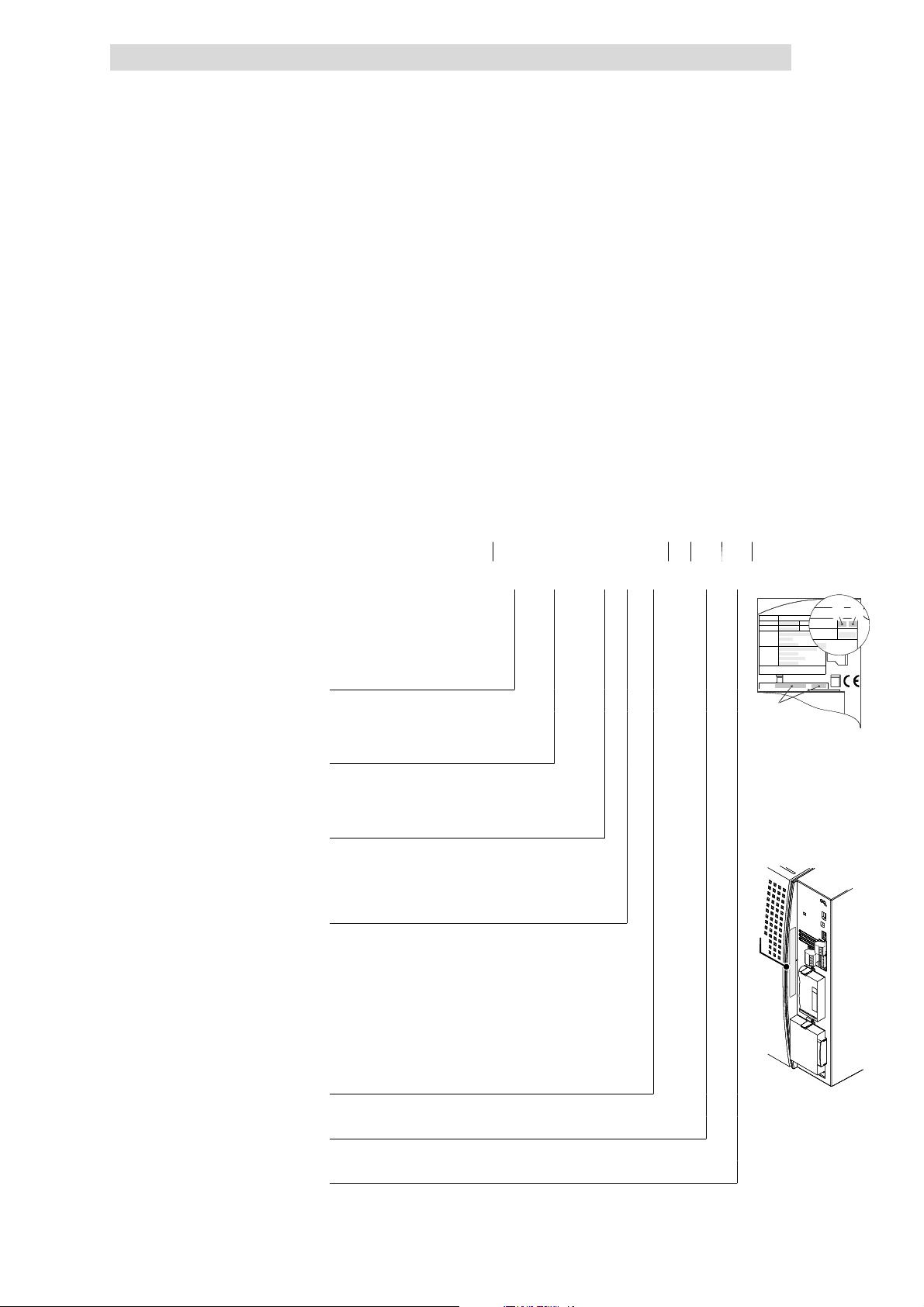
Basic device installation
Show/Hide Bookmarks
5
Important notes
5.2 Important notes
l 8200 vector frequency inverters should only be used as built-in units
l If the cooling air contains pollutants (dust, fluff, grease, aggressive gases)
l Free space:
l With continuous vibrations and shocks: Use shock absorbers.
l The indicated dimensions apply to types according to this key:
5.2
ensure suitable measures to protect the inverter (e.g. filters, regular
cleaning, etc.)
– It is possible to mount several devices side by side with a clearance
depending on the corresponding type.
– Ensure unimpeded ventilation of cooling air and outlet of exhaust air.
– Allow a free space of 100 mm above and below the inverter.
E82xV xxx K x x xxx 3x 3x
Type
E = Built-in unit
D = Built-in unit in push-through
technique
C = Built-in unit in “Cold Plate”
technique
Power
(e.g.152=15
(e.g.113=11
× 10
× 10
2
W=1.5kW)
3
W=11kW)
Voltage class
2 = 230 V
4 = 400 V/500 V
Controller generation
C (0.25 ... 11 kW)
B (15 ... 90 kW)
Version, variant
0xx = EMC filter integrated
1xx = For IT systems (15 ... 90 kW)
2xx = Without EMC filter
x0x = Without function ”Safe standstill”
x4x = With function ”Safe standstill” (3 ... 90 kW)
xx0 = Not coated
xx1 = Coated
Hardware version
Hans-Lenze-Str.1
Hans-Lenze-Str.1
Hans-Lenze-Str.1
Hans-Lenze-Str.1
D-31855Aerzen
D-31855Aerzen
D-31855Aerzen
D-31855Aerzen
Inverter
Inverter
Inverter
Inverter
8200 vector
8200 vector
8200 vector
8200 vector
Id.-No:
Id.-No:
Id.-No:
Id.-No:
Version:
Version:
Version:
Version:
Ser.-No:
Ser.-No:
Ser.-No:
Ser.-No:
Prod.-No:
Prod.-No:
Prod.-No:
Prod.-No:
Input:
Input:
Input:
Input:
Output:
Output:
Output:
Output:
Fordetailed information refer to the manual
Fordetailed information refer to the manual
Fordetailed information refer to the manual
Fordetailed information refer to the manual
EDK82EV222
EDK82EV222
EDK82EV222
EDK82EV222
Made in Germany
Made in Germany
Made in Germany
Made in Germany
Type:
Type:
Type:
Type:
_
_
_
_
0.25 ... 11 kW
E82xVxxxK4Bxxx xx xx xxE82xVxxxK4Bxxx xx xx xx
E82xVxxxK4Bxxx xx xx xx
15 ... 90 kW
1D74
1D74
1D74
1D74
IndustrialControl
Equipment
IndustrialControl
Equipment
IndustrialControl
Equipment
IndustrialControl
Equipment
K
K
K
K
L
Software version
EDS 82EV903-1.0-11/2002
5.2-1
Page 86

Show/Hide Bookmarks
Page 87
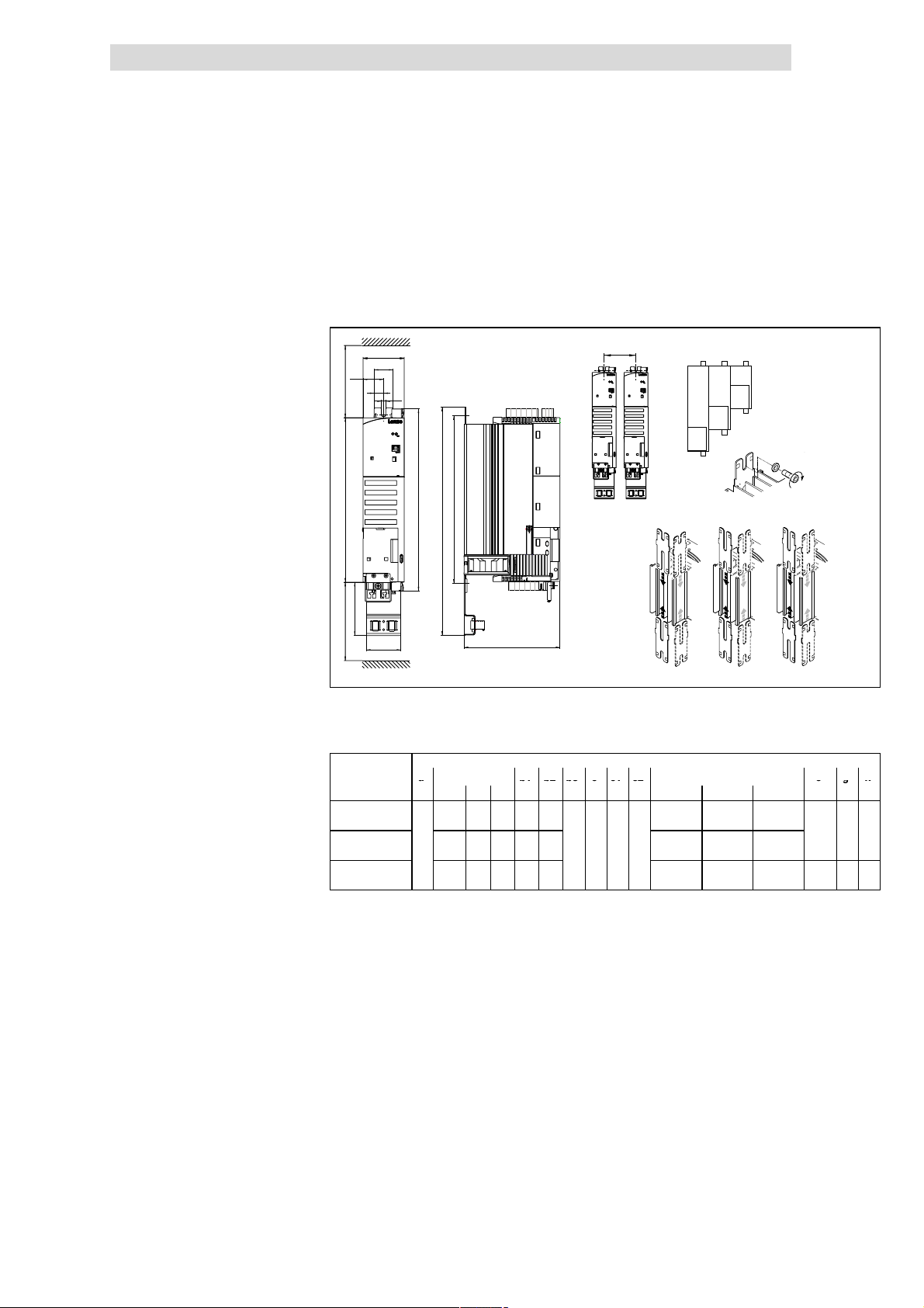
Basic device installation
a
b1b2b3cc1c2
egk
Show/Hide Bookmarks
5
Basic units in the power range 0.25 ... 2.2 kW
Mounting with fixing rails (standard)
5.3 Basic units in the power range 0.25 ... 2.2 kW
5.3.1 Mounting with fixing rails (standard)
8200 vector 0.25 ... 2.2 kW
>100 mm
b2
a
k
c
g
d
b
b1
c1
5.3.1
0
M6
4Nm
35 lbin
123
5.3
b3
>100 mm
c2
Fig. 5.3-1 Standard mounting with fixing rails 0.25 ... 2.2 kW
Different sizes can only be mounted side by side when the smaller units are
0
mounted to the right-hand-side of the bigger units!
a b b1 b2 b3 c c1 c2 d e g k
1 2 3
E82EV251K2C
E82EV371K2C
E82EV551KxC
E82EV751KxC
E82EV152KxC
E82EV222KxC
1)
Lateral mounting only possible with swivel mounting unit E82ZJ001 (accessories)
2)
with E82ZJ001
213 243 263 148 120 130...140 120...170 110...200
60
273 303 323 208 180
1)
333
359
2)
1)
e
363 - 268 240
Dimensions [mm]
78 30 63 50
1 2 3
190...200 180...230 170...260
250...260
280...295
240...290 -
2)
28200vec004
140 6.5 28
140
6.5 28
2)
162
L
EDS 82EV903-1.0-11/2002
5.3-1
Page 88
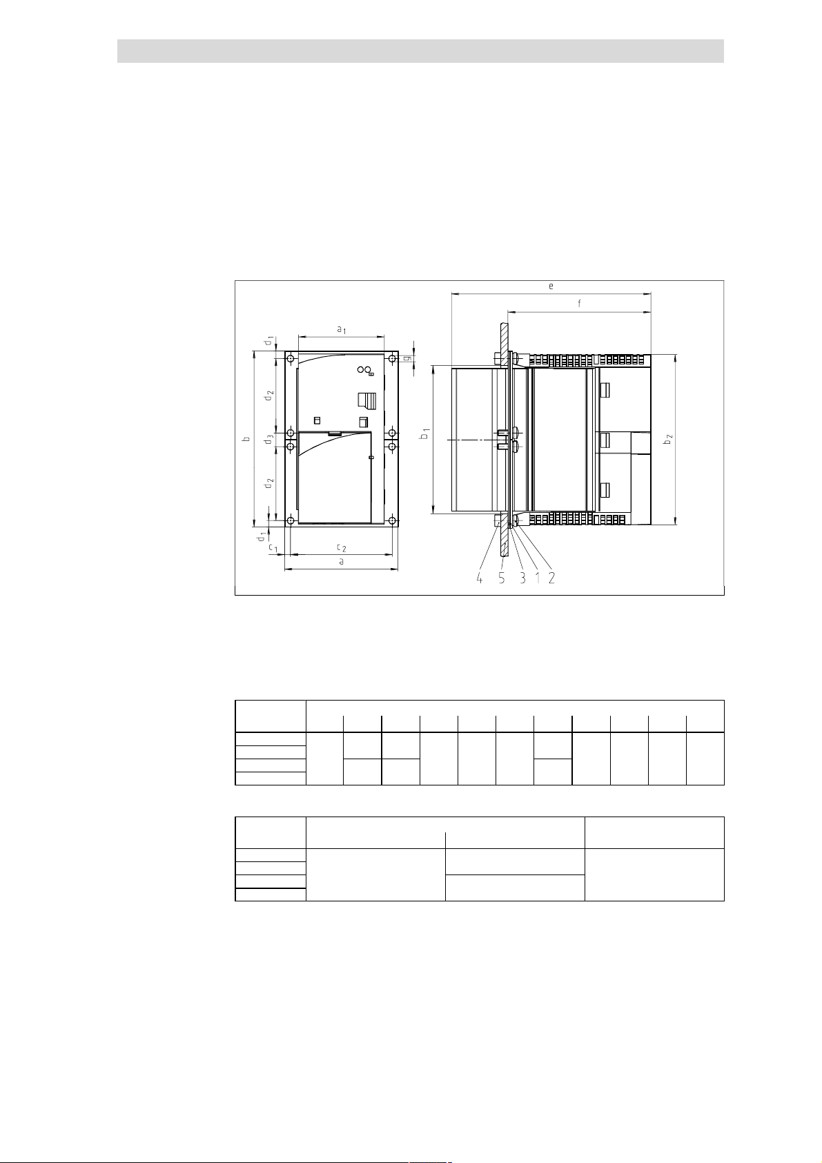
5
12412
052
4
4.2715101401004
1841808
2
101
61E82ZJ00
3
161
Show/Hide Bookmarks
Basic device installation
5.3
5.3.2
Thermally separated mounting (push-through technique)
Basic units in the power range 0.25 ... 2.2 kW
5.3.2 Thermally separated mounting (push-through t echnique)
For mounting in push-through technique use the controller type E82 D V... . The
delivery package includes all parts and components required for mounting.
8200 vector 0.25 ... 0.75 kW
Fig. 5.3-2 Dimensions for thermally separated mounting 0.25 ... 0.75 kW
1 Fixing frames
2ScrewM4x10
3 Gasket
4 Hex nut M4
5 Control cabinet rear panel
Dimensions [mm]
8200 vector a b b
E82DV251K2C
E82DV371K2C
E82DV551KxC
E82DV751KxC
79.
c
c
d
d
2
1
2
1
d
2
3
Cutout in control cabinet
Dimensions [mm]
8200 vector a
E82DV251K2C
E82DV371K2C
E82DV551KxC
E82DV751KxC
1
b
1
8200vec027
e f g
.5
Fixing frames
5.3-2
EDS 82EV903-1.0-11/2002
L
Page 89
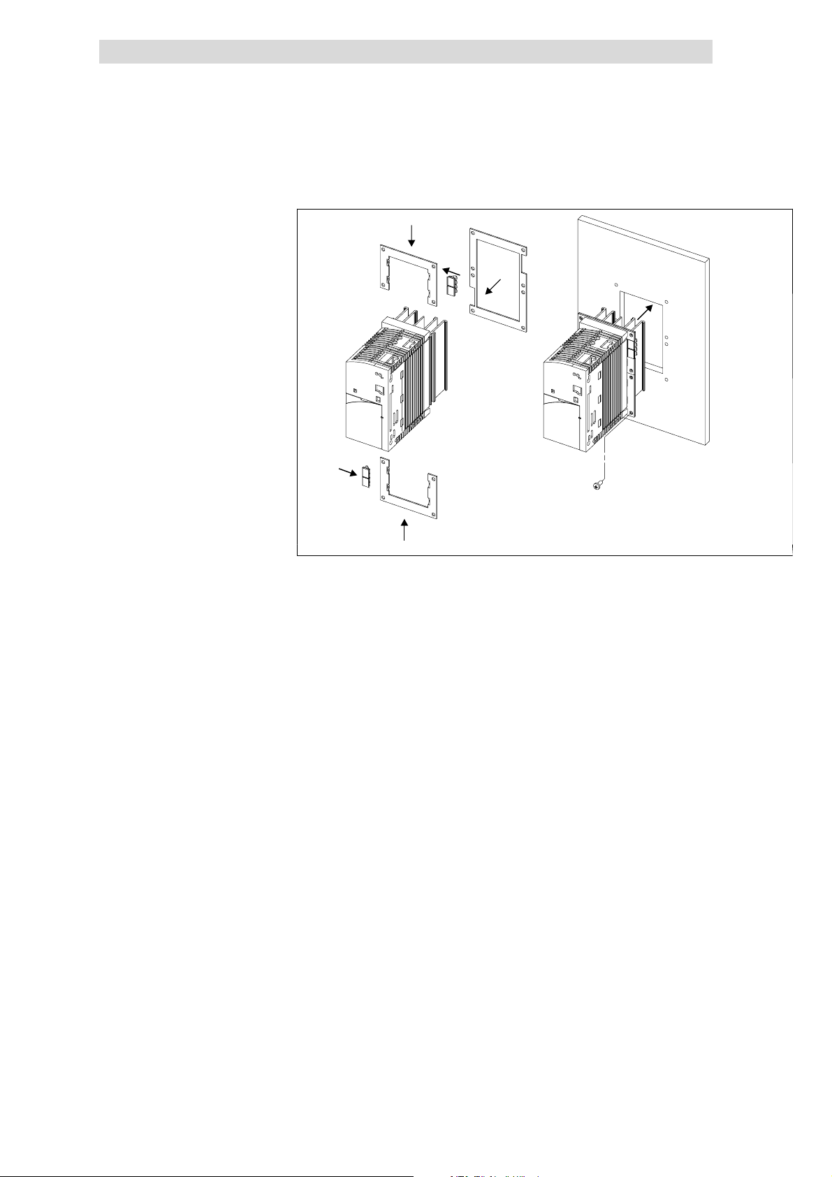
Basic device installation
Show/Hide Bookmarks
5
Basic units in the power range 0.25 ... 2.2 kW
Thermally separated mounting (push-through technique)
Mounting
3.
1.
3.
5.3
5.3.2
2.
4.
5.
1.
Fig. 5.3-3 Thermally separated mounting 0.25 ... 0.75 kW
1. Push in the fixing frames
2 Insert seal
3. Push the grounding terminals with the correct end onto the fixing frame:
– The contact springs must point to the rear panel of the control cabinet
– The cutouts of the seal determine the positions
4.
Insert the 8200vector into the cutout
5. Fasten it with 8 M4x10 screws
E82DV_001
L
EDS 82EV903-1.0-11/2002
5.3-3
Page 90
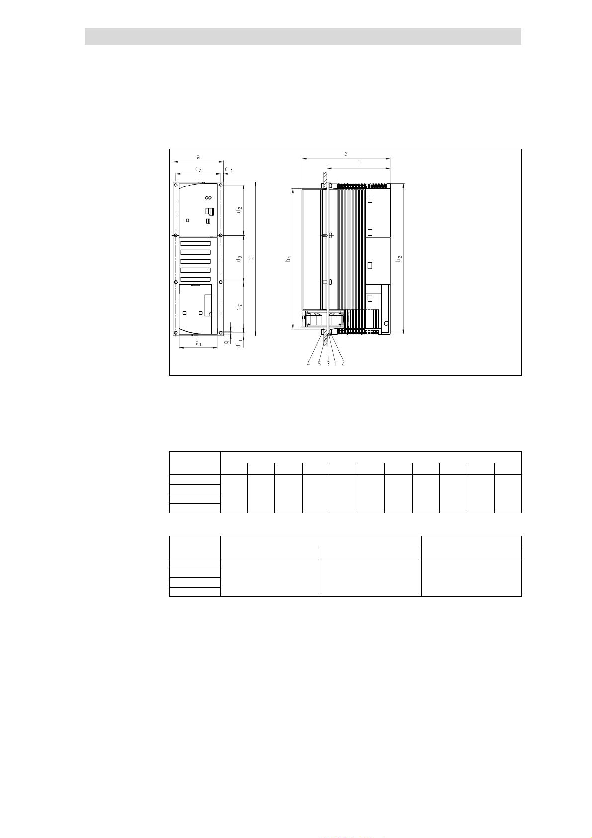
5
424
4.5240
4.27158
074.51401004
61221E82ZJ0
0
Show/Hide Bookmarks
Basic device installation
5.3
5.3.2
8200 vector 1.5 ... 2.2 kW
Basic units in the power range 0.25 ... 2.2 kW
Thermally separated mounting (push-through technique)
Fig. 5.3-4 Dimensions for thermally separated mounting 1.5 ... 2.2 kW
1 Fixing frames
2ScrewM4x10
3 Gasket
4 Hex nut M4
5 Control cabinet rear panel
Dimensions [mm]
8200 vector a b b
E82DV152K2C
E82DV222K2C
E82DV152K4C
E82DV222k4C
79.
c
c
d
2
1
2
d
1
2
Cutout in control cabinet
Dimensions [mm]
8200 vector a
E82DV152K2C
E82DV222K2C
E82DV152K4C
E82DV222k4C
1
b
1
d
3
8200vecxxx
e f g
,5
Fixing frames
x
5.3-4
EDS 82EV903-1.0-11/2002
L
Page 91
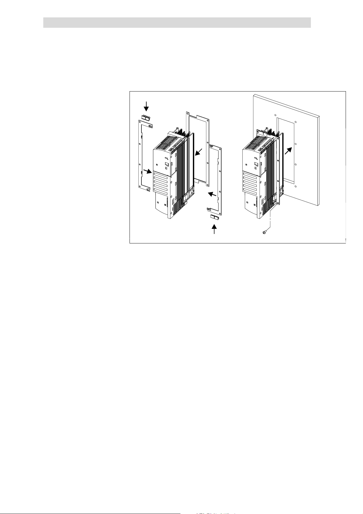
Basic device installation
Show/Hide Bookmarks
5
Basic units in the power range 0.25 ... 2.2 kW
Thermally separated mounting (push-through technique)
Mounting
3.
2.
1.
5.3
5.3.2
4.
1.
3.
Fig. 5.3-5 Thermally separated mounting 1.5 ... 2.2 kW
1. Push in the fixing frames
2 Insert seal
3. Push the grounding terminals with the correct end onto the fixing frame:
– The contact springs must point to the rear panel of the control cabinet
– The cutouts of the seal determine the positions
4.
Insert the 8200vector into the cutout
5. Fasten it with 8 M4x10 screws
5.
E82DV_002
L
EDS 82EV903-1.0-11/2002
5.3-5
Page 92
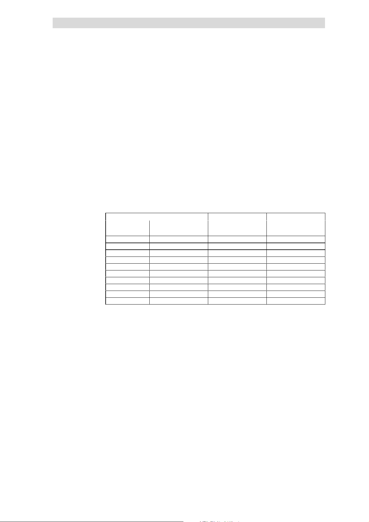
5
Show/Hide Bookmarks
Basic device installation
5.3
5.3.3
5.3.3 Mounting in ”cold plate” technique
When using ”coldplate” technique the controllers can be mounted to sum
coolers.Use controllers oftyp e E82CV... .
Requirements on the cooler
The following points are important to ensure a safe operation of the drive
controllers:
l Good thermal contact with the cooler:
– The contact area between the cooler and the drive controller must be at
least as large as the cooling plate of the drive controller.
– Plane contact area, deviation max. to 0.05 mm.
– The cooler and heatsink must be attached using all the screwed joints
that are specified.
l Thermal resistance R
withthe drivecontrollersunder ratedc onditions.
8200 vector Cooling path Ground
Power to be dissipated Heatsink - environment
Typ e P
E82CV251K2C 15 ≤ 1.50 0.6
E82CV371K2C 20 ≤ 1.50 0.6
E82CV551K2C 30 ≤ 1.00 0.9
E82CV751K2C 40 ≤ 1.00 0.9
E82CV152K2C 70 ≤ 0.30 1.1
E82CV222K2C
E82CV551K4C 30 ≤ 1.00 0.9
E82CV751K4C 40 ≤ 1.00 0.9
E82CV152K4C 65 ≤ 0.30 1.1
E82CV222K4C 100 ≤ 0.30 1.1
1)
Max. output current at 8 kHz chopper frequency: 8.5 A!
1)
Basic units in the power range 0.25 ... 2.2 kW
Mounting in ”cold plate” technique
according to table. The values are valid for operation
th
[W] Rth[°C/W] [kg]
loss
100 ≤ 0.30 1.1
Environmental conditions
l Ambient temperature - controllers
– The rated data and the derating for higher temperatures still apply for the
ambient temperature of the drive controller.
l Heat distribution between common heatsinks/coolers within the control
cabinet
– If you mount several components ( drive controller, brake units etc.) on a
common cooler, then care must be taken that the temperature of the
controller heatsinks does not exceed 75 °C.
5.3-6
EDS 82EV903-1.0-11/2002
L
Page 93
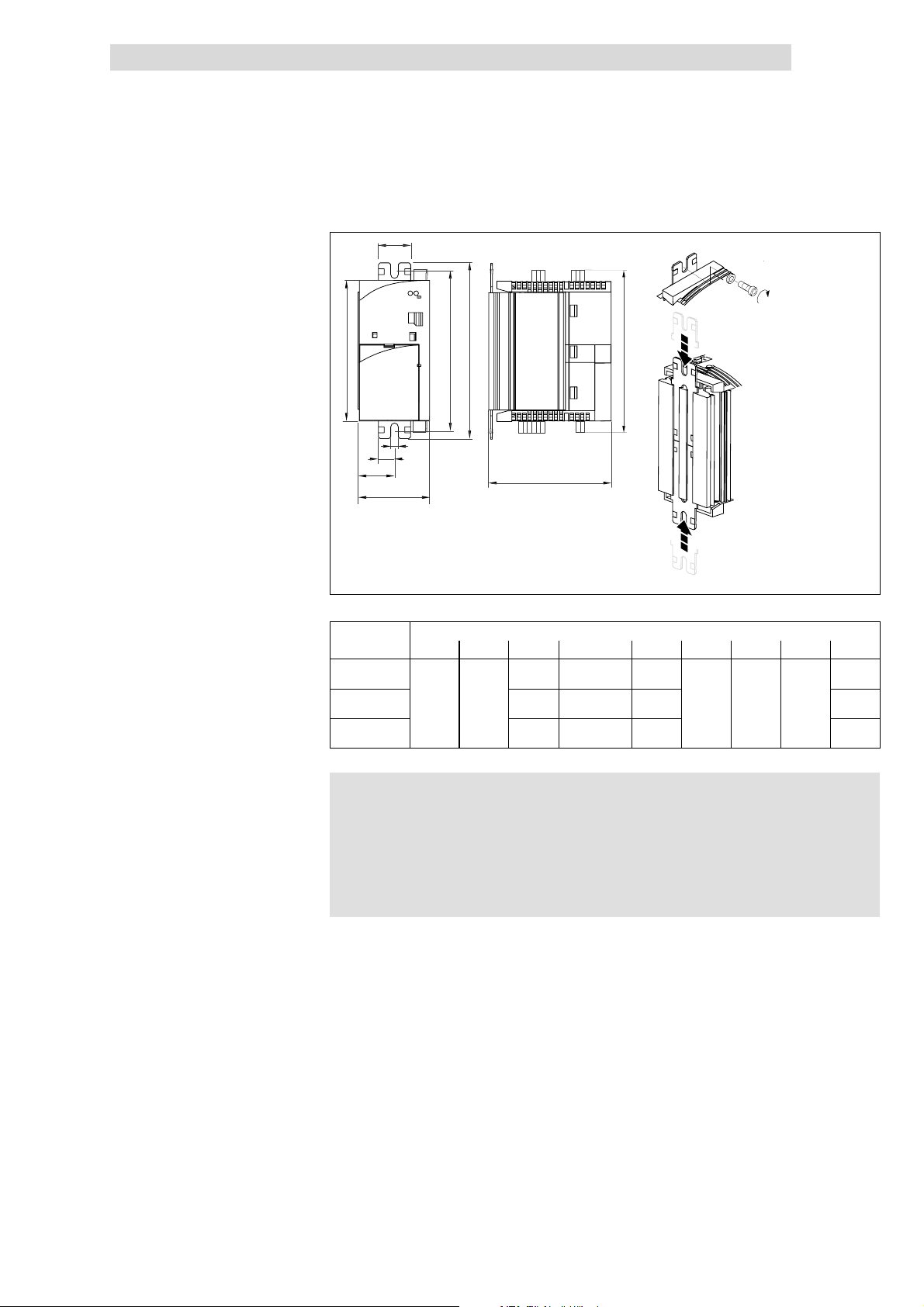
Basic device installation
Show/Hide Bookmarks
5
Basic units in the power range 0.25 ... 2.2 kW
Mounting in ”cold plate” technique
8200 vector 0.25 ... 2.2 kW
b2
e
d
c1
a1
a
5.3
5.3.3
M6
4Nm
35 lbin
b
b1
c
f
Mounting
8200vec029
Fig. 5.3-6 Dimensions for mounting in ”Co ld plate” technique 0.25 ... 2.2 kW
Dimensions [mm]
8200 vector a a1 b b1 b2 c d e f
E82CV251K2B
E82CV371K2B
E82CV551KxB
E82CV751KxB
E82CV152KxB
E82CV222KxB
)
) Note!
))
1. Slide the mounting rails into the heatsink from the top and from the bottom
2. Clean the area of contact between the heatsink and the cooler with
methylated spirits.
3. Apply a thin layer of heat-conducting paste.
4. Bolt the drive controller onto the cooler using two screws.
60 30
l Apply heat-conducting paste before you bolt together the
cooler and the heatsink to keep the thermal resistance as low
aspossible.
l The quantity of heat-conducting paste supplied in the delivery
package is sufficient for approx. 1000 cm
150 130 ... 140 120 148
210 190 ... 200 180
270 250 ... 260 240 268
106 6.5 27.5
2
.
208
L
EDS 82EV903-1.0-11/2002
5.3-7
Page 94
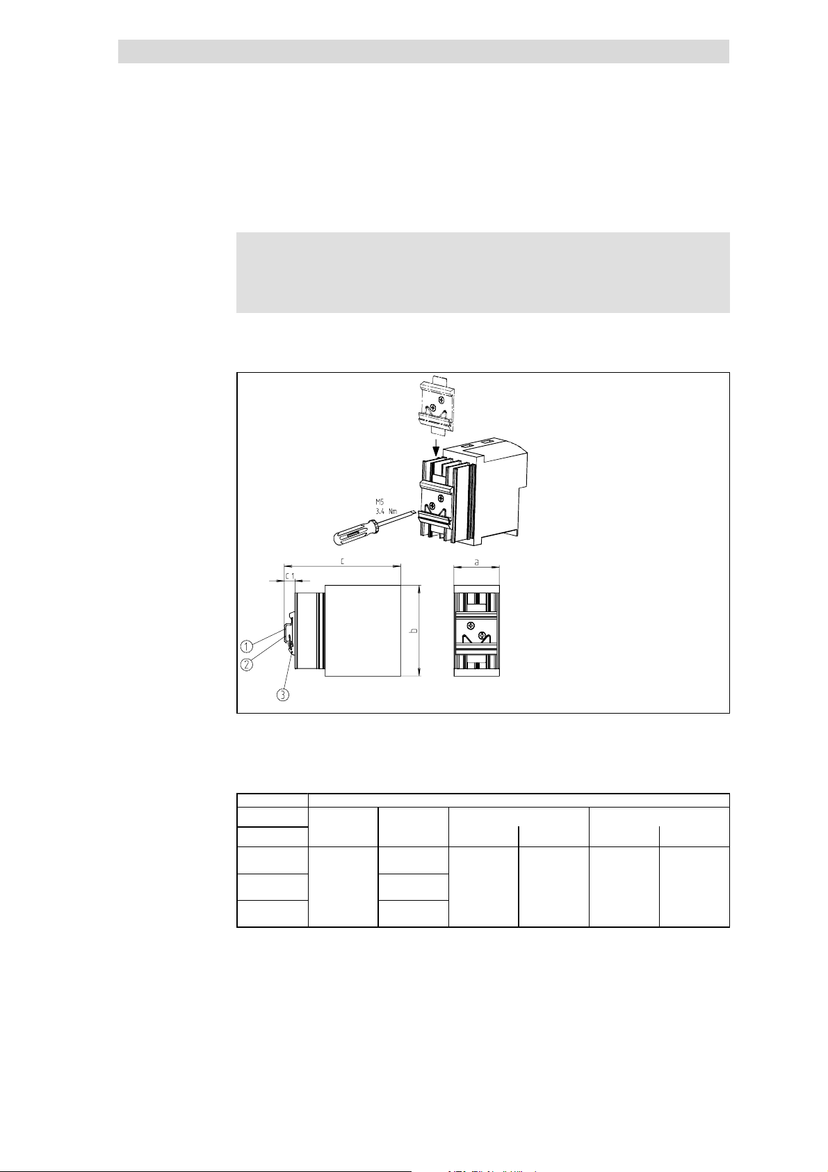
5
Show/Hide Bookmarks
Basic device installation
5.3
5.3.4
5.3.4 DIN rail mo unting
The accessories for DIN rail mounting are not included in the delivery package.
Order number: E82ZJ002 for 8200 vector 0.25 ... 2.2 kW
)
) Note!
))
This mounting variant does not enable a CE-typical drive system
to be installed.
Basic units in the power range 0.25 ... 2.2 kW
DIN rail mounting
Fig. 5.3-7 DIN rail mounting 0.25 ... 2.2kW
DIN rail 35 x 15
DIN rail 35 x 7.5
DIN rail mounting
Dimensions [mm]
a b c c
8200 vector
E82EV251K2C
E82EV371K2C
E82EV551KxC
E82EV751KxC
E82EV152KxC
E82EV222KxC
60
120
180
240
158 151 18 11
1
820vec025
5.3-8
EDS 82EV903-1.0-11/2002
L
Page 95
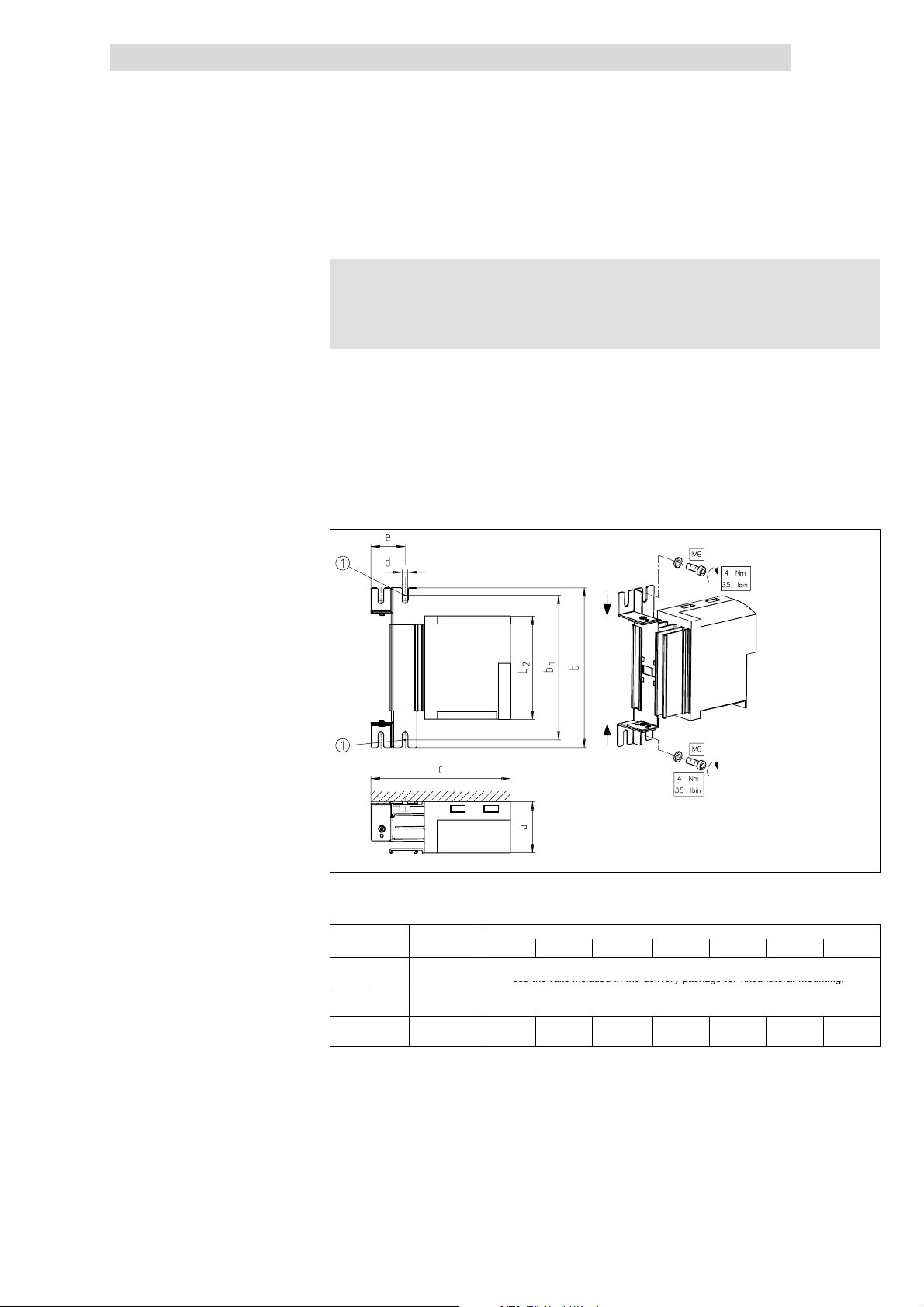
Basic device installation
Usetherailsincludedinthedeliverypackageforfixedlateralmounting.
Show/Hide Bookmarks
5
Basic units in the power range 0.25 ... 2.2 kW
Lateral mounting
5.3.5 Lateralmounting
)
) Note!
))
This mounting variant does not enable a CE-typical drive system
to be installed.
Lateral mounting ofthecontrolleris possibleonboth sides. Thecontroller iseither
fixed or can be swivelled depending on themounting point. Both mounting types
use the same mounting kit.
Fixed lateral mounting
l The controllers 0.25 ... 0.75 kW can be mounted with the rails included in
the delivery package.
l The controllers 1.5 ... 2.2 kW require a mounting kit.
– Order number E82ZJ001 for 8200 vector 1.5 ... 2.2 kW
5.3
5.3.5
L
Fig. 5.3-8 Fixed lateral mounting
Bolt here
8200 vector Mounting kit a b b
E82EV251K2C
E82EV371K2C
E82EV551KxC
E82EV751KxC
E82EV152KxC
E82EV222KxC
-
E82ZJ001 60 306 280 ... 295 240 162 6.5 39
EDS 82EV903-1.0-11/2002
Use the rails included in the delivery package for fixed lateral mounting.
Dimensions in mm
1
Dimensions: ^ 5.3-1
b
2
8200vec074
c d e
5.3-9
Page 96
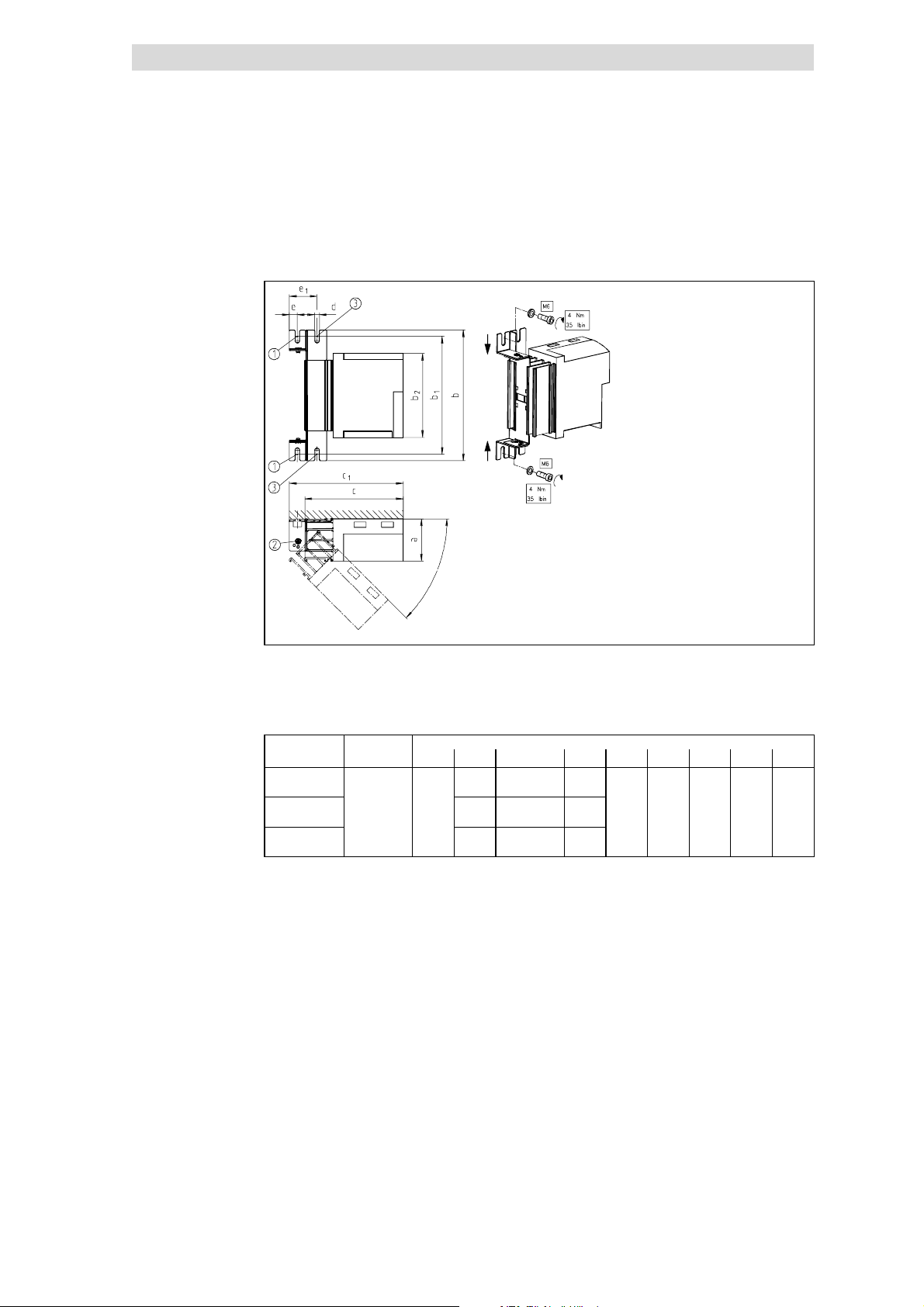
5
Show/Hide Bookmarks
Basic device installation
5.3
5.3.5
Swivelling lateral mounting
Basic units in the power range 0.25 ... 2.2 kW
All controllers require a mounting kit:
l
– Order number E82ZJ001 for 8200 vector 0.25 ... 2.2 kW
Lateral mounting
Fig. 5.3-9 Swivelling lateral mounting
Bolt here
Rotating point, stops at45°,90°, 135°, 180°
Bolt here to fasten the controller at 0° position.
8200 vector Mounting kit a b b
E82EV251K2C
E82EV371K2C
E82EV551KxC
E82EV751KxC
E82EV152KxC
E82EV222KxC
E82ZJ001 60
186 160 ... 175 120
246 220 ... 235 180
306 280 ... 295 240
8200vec024
Dimensions [mm]
b
1
c c
2
140 162 6.5 11.5 39
1
d e e
1
5.3-10
EDS 82EV903-1.0-11/2002
L
Page 97
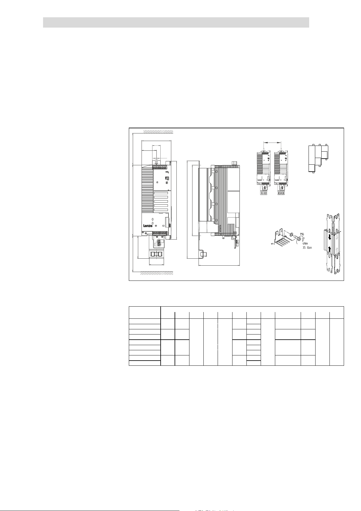
Basic device installation
333
255
140
2682407
8
5
0
6.528
1003335
0
25514
0
333
255
140
Show/Hide Bookmarks
5
Basic units in the power range 3 ... 11 kW
Mounting with fixing rails (standard)
5.4 Basic unitsin the power range 3 ... 11 kW
5.4.1 Mounting with fixing rails (standard)
8200 vector 3 ... 11 kW
a
k
c
> 100 mm
b2
g
b1
d
b
5.4
5.4.1
c1
0
b3
> 100 mm
c2
e
8200vec060
Fig. 5.4-1 Standard mounting with fixing rails 3 ... 11 kW
Different sizes can only be mounted side by side when the smaller units are
0
mounted to the right-hand-side of the bigger units!
Dimensions in mm
8200 vector a b b1 b2 b3 c c1 c2 d e g k
E82EV302K2C
E82EV402K2C
E82EV552K2C
E82EV752K2C
E82EV302K4C
E82EV402K4C
E82EV552K4C
E82EV752K4C
E82EV113K4C
100 333 50
1)
1)
1)
1)
333
125
359
100 333
333
125
359
2)
268 240 78
2)
62.5
50
62.5
103
103
128
128
50 6.5 28
103
103
103
128
128
255 140
255 140
280 ... 295
255 140
255 140
280 ... 295
2)
2)
162
162
2)
2)
1) Side mounting only possible with swivel holding unit E82ZJ006 (accessories)
2) with E82ZJ006
L
EDS 82EV903-1.0-11/2002
5.4-1
Page 98
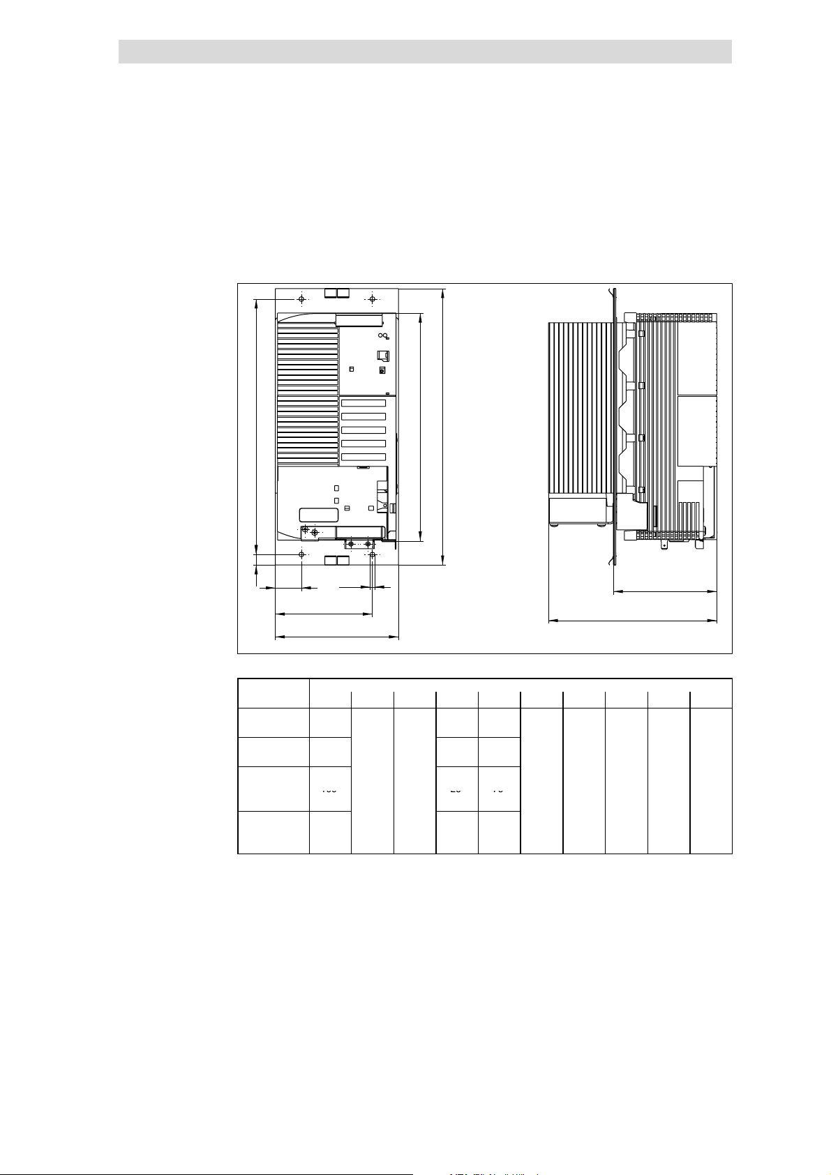
5
29224
0
270
17810
9
1
1
1002575
Show/Hide Bookmarks
Basic device installation
5.4
5.4.2
Thermally separated mounting (push-through technique)
Basic units in the power range 3 ... 11 kW
5.4.2 Thermally separated mounting (push-through t echnique)
For mounting in push-through technique use the controller type E82 D V... . The
delivery package includes all parts and components required for mounting.
8200 vector 3 ... 11 kW
b
d
b1
h
c1
Fig. 5.4-2 Dimensions for thermally separated mounting 3 ... 11 kW
8200 vector a b b1 c1 c2 d e e1 g h
E82DV302K2C
E82DV402K2C
E82DV552K2C
E82DV752K2C
E82DV302K4C
E82DV402K4C 100
E82DV552K4C
E82DV752K4C
E82DV113K4C 130 27.5 102.5
g
c2
a
100 25 75
130 27.5 102.5
25 75
e1
e
8200vec327
Dimensions [mm]
.5 5
5.4-2
EDS 82EV903-1.0-11/2002
L
Page 99
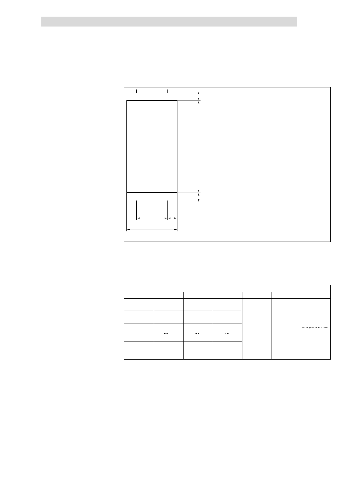
Basic device installation
1
1
224
+
1
2
3
integratedwit
h
80501
5
Show/Hide Bookmarks
5
Basic units in the power range 3 ... 11 kW
Thermally separated mounting (push-through technique)
Mounting
5.4
5.4.2
b3
b2
b3
a2 a3
a1
Fig. 5.4-3 Dimensions for thermally separated mounting cutout 3 ... 11 kW
1. Push the grounding terminals with the correct end onto the fixing frame:
– The contact springs must point to the rear panel of the control cabinet
– The cutouts of the seal determine the positions
2
Insert the 8200vector into the cutout
3. Fasten it with 4 M4x10 screws
Dimensions [mm]
8200 vector a1 a2 a3 b2 b3 Fixing frames
E82DV302K2C
E82DV402K2C
E82DV552K2C
E82DV752K2C
E82DV302K4C
E82DV402K4C 80
E82DV552K4C
E82DV752K4C
E82DV113K4C 123
80
123
+
+
+1
+1
50 15
75 24
50 15
75 24
8200vec310
integrated with
seal
L
EDS 82EV903-1.0-11/2002
5.4-3
Page 100
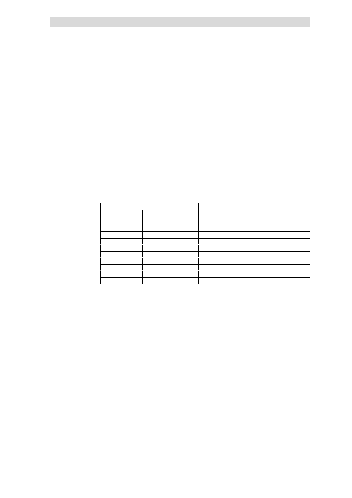
5
Show/Hide Bookmarks
Basic device installation
5.4
5.4.3
5.4.3 Mounting in ”cold plate” technique
When using ”coldplate” technique the controllers can be mounted to sum
coolers.Use controllers oftyp e E82CV... .
Requirements on the cooler
The following points are important to ensure a safe operation of the drive
controllers:
l Good thermal contact with the cooler:
– The contact area between the cooler and the drive controller must be at
least as large as the cooling plate of the drive controller.
– Plane contact area, deviation max. to 0.05 mm.
– The cooler and heatsink must be attached using all the screwed joints
that are specified.
l Thermal resistance R
withthe drivecontrollersunder ratedc onditions.
8200 vector Cooling path Ground
Power to be dissipated Heatsink - environment
Typ e P
E82CV302K2C 110 ≤ 0.23 2.4
E82CV402K2C 150 ≤ 0.23 2.4
E82CV552K2C 205 ≤ 0.13 3
E82CV752K2C 270 ≤ 0.13 3
E82CV302K4C 110 ≤ 0.23 2.4
E82CV402K4C 140 ≤ 0.23 2.4
E82CV552K4C 190 ≤ 0.23 3
E82CV752K4C 255 ≤ 0.13 3
E82CV113K4C 360 ≤ 0.13 3
Basic units in the power range 3 ... 11 kW
Mounting in ”cold plate” technique
according to table. The values are valid for operation
th
[W] Rth[°C/W] [kg]
loss
Environmental conditions
l Ambient temperature - controllers
– The rated data and the derating for higher temperatures still apply for the
ambient temperature of the drive controller.
l Heat distribution between common heatsinks/coolers within the control
cabinet
– If you mount several components ( drive controller, brake units etc.) on a
common cooler, then care must be taken that the temperature of the
controller heatsinks does not exceed 75 °C.
5.4-4
EDS 82EV903-1.0-11/2002
L
 Loading...