


Lenovo TAB 2 A10-30
Hardware Maintenance Manual
Lenovo TB2-X30F
Lenovo TB2-X30L
Lenovo TB2-X30M

Note:
Before using this information and the product it supports, be sure to read the general information under “Notices” on page 82.
First Edition (Sep 2015)
© Copyright Lenovo 2015. All rights reserved.
LENOVO products, data, computer software, and services have been developed exclusively at private expense and are sold to governmental entities as commercial items as defined by 48 C.F.R. 2.101 with limited and restricted rights to use, reproduction and disclosure.
LIMITED AND RESTRICTED RIGHTS NOTICE: If products, data, computer software, or services are delivered pursuant to a General Services Administration “GSA” contract, use, reproduction, or disclosure is subject to restrictions set forth in Contract No. GS-35F-05925.
© 2014 Lenovo

Contents
About this manual........................................ |
iv |
Safety information......................................... |
1 |
General safety ...................................................... |
2 |
Electrical safety .................................................... |
3 |
Safety inspection guide ...................................... |
5 |
Handling devices that are sensitive to electro- |
|
static discharge .................................................... |
6 |
Grounding requirements ................................... |
6 |
Safety notices: multilingual translations.......... |
7 |
Laser compliance statement............................. |
14 |
Important service information ................... |
16 |
Strategy for replacing FRUs............................. |
16 |
Important notice for replacing a system |
|
board ............................................................. |
17 |
Important information about replacing RoHS |
|
compliant FRUs ................................................. |
18 |
General checkout........................................ |
19 |
What to do first .................................................. |
20 |
Power system checkout .................................... |
21 |
Checking the Computer AC Charger....... |
21 |
Checking the internal battery status......... |
22 |
Related service information....................... |
23 |
Security ............................................................... |
23 |
Power management .......................................... |
23 |
Activating/Deactivating the Display ........ |
23 |
Lenovo TAB 2 A10-30 ................................. |
24 |
Specifications ..................................................... |
24 |
Components location ........................................ |
26 |
Front view .................................................... |
26 |
Rear view...................................................... |
27 |
Parts list .............................................................. |
28 |
FRUs list........................................................ |
28 |
Screws list ..................................................... |
32 |
FRU replacement notices.................................. |
33 |
Screw notices................................................ |
33 |
Removing and replacing an FRU.................... |
34 |
1010 Rear cover and side key..................... |
35 |
1020 Battery pack......................................... |
37 |
1030 Rear camera......................................... |
41 |
1040 Microphone ......................................... |
42 |
1050 Vibrator motor .................................... |
44 |
1060 LCD FPC.............................................. |
46 |
1070 Main FPC ............................................. |
51 |
1080 Antenna PCB (LTE version only)..... |
55 |
1090 Sub board............................................. |
58 |
1100 Left Speaker ......................................... |
62 |
1110 Right Speaker ...................................... |
65 |
1120 Main board assembly (with left and |
|
right speakers, audio jack FPC, and side key |
|
FPC) ............................................................... |
68 |
1130 Front camera........................................ |
75 |
Notices ......................................................... |
82 |
Trademarks......................................................... |
83 |

About this manual
This manual contains service and reference information for the following Lenovo products:
•Lenovo TB2-X30F (WiFi)
•Lenovo TB2-X30L (LTE data)
•Lenovo TB2-X30M (LTE voice)
Use this manual to troubleshoot problems.
The manual is divided into the following sections:
•The common sections provide general information, guidelines, and safety information required for servicing computers.
•The product-specific section includes service, reference, and product-specific parts information.
iv

Safety information
Safety information
This chapter presents the following safety information that you need to get familiar with before you service a Lenovo computer:
•“General safety” on page 2
•“Electrical safety” on page 3
•“Safety inspection guide” on page 5
•“Handling devices that are sensitive to electrostatic discharge” on page 6
•“Grounding requirements” on page 6
•“Safety notices: multilingual translations” on page 7
•“Laser compliance statement” on page 14
1

 Lenovo TAB 2 A10-30 Hardware Maintenance Manual
General safety
Follow these rules below to ensure general safety:
•Observe a good housekeeping in the area where the machines are put during and after the maintenance.
•When lifting any heavy object:
1.Make sure that you can stand safely without slipping.
2.Distribute the weight of the object equally between your feet.
3.Use a slow lifting force. Never move suddenly or twist when you attempt to lift it.
4.Lift it by standing or pushing up with your leg muscles; this action could avoid the strain from the muscles in your back. Do not attempt to lift any object that weighs more than 16 kg (35 lb) or that you think is too heavy for you.
•Do not perform any action that causes hazards to the customer, or that makes the machine unsafe.
•Before you start the machine, make sure that other service representatives and the customer are not in a hazardous position.
•Place removed covers and other parts in a safe place, keeping them away from all personnel, while you are servicing the machine.
•Keep your toolcase away from walk areas so that other people will not trip it over.
•Do not wear loose clothing that can be trapped in the moving parts of the machine. Make sure that your sleeves are fastened or rolled up above your elbows. If your hair is long, fasten it.
•Insert the ends of your necktie or scarf inside clothing or fasten it with the nonconductive clip, about 8 centimeters (3 inches) from the end.
•Do not wear jewelry, chains, metal-frame eyeglasses, or metal fasteners for your clothing.
Attention: Metal objects are good electrical conductors.
•Wear safety glasses when you are hammering, drilling, soldering, cutting wire, attaching springs, using solvents, or working in any other conditions that may be hazardous to your eyes.
•After service, reinstall all safety shields, guards, labels, and ground wires. Replace any safety device that is worn or defective.
•Reinstall all covers correctly before returning the machine to the customer.
•Fan louvers on the machine help to prevent the overheating of internal components. Do not obstruct fan louvers or cover them with labels or stickers.
2

Safety information
Electrical safety
Observe the following rules when working on electrical equipments.
•Find the room emergency power-off (EPO) switch for disconnecting the switch or electrical outlet. If an electrical accident occurs, you can then operate the switch or unplug the power cord quickly.
•Do not work alone under hazardous conditions or near the equipment that has hazardous voltages.
•Disconnect all power before:
—Performing a mechanical inspection
—Working near power supplies
—Removing or installing main units
•Before you start to work on the machine, unplug the power cord. If you cannot unplug it, ask the customer to power-off the wall box that supplies power to the machine, and to lock the wall box in the off position.
•If you need to work on a machine that has exposed electrical circuits, observe the following precautions:
—Ensure that another person, familiar with the power-off controls, is near you.
Attention: Another person must be there to switch off the power, if necessary.
—Use only one hand when working with powered-on electrical equipment; keep the other hand in your pocket or behind your back.
Attention: An electrical shock can occur only when there is a complete circuit. By observing the above rule, you may prevent a current from passing through your body.
—When using testers, set the controls correctly and use the approved probe leads and accessories for that tester.
—Stand on suitable rubber mats (obtained locally, if necessary) to insulate you from grounds such as metal floor strips and machine frames.
Observe the special safety precautions when you work with very high voltages; instructions for these precautions are in the safety sections of maintenance information. Be extremely careful when you measure the high voltages.
•Regularly inspect and maintain your electrical hand tools for safe operational condition.
•Do not use worn or broken tools and testers.
•Never assume that power has been disconnected from a circuit. First, check it to make sure that it has been powered off.
3
 Lenovo TAB 2 A10-30 Hardware Maintenance Manual
•Always look carefully for possible hazards in your work area. Examples of these hazards are moist floors, nongrounded power extension cables, power surges, and missing safety grounds.
•Do not touch live electrical circuits with the reflective surface of a plastic dental mirror. The surface is conductive; such touching can cause personal injury and machine damage.
•Do not service the following parts with the power on when they are removed from their normal operating places in a machine:
—Power supply units
—Pumps
—Blowers and fans
—Motor generators
and similar units. (This practice ensures correct grounding of the units.)
•If an electrical accident occurs:
—Caution: do not become a victim yourself.
—Switch off the power.
—Send the victim to get medical aid.
4

Safety information
Safety inspection guide
The purpose of this inspection guide is to assist you in identifying potential unsafe conditions. As each machine was designed and built, required safety items were installed to protect users and service personnel from injury. This guide addresses only those items. You should use good judgment to identify potential safety hazards according to the attachment of non-Lenovo features or options not covered by this inspection guide.
If any unsafe conditions are present, you must determine how serious the apparent hazard could be and whether you can continue without first correcting the problem.
Consider these conditions and the safety hazards they present:
•Electrical hazards, especially primary power (primary voltage on the frame can cause serious or fatal electrical shock)
•Explosive hazards, such as a damaged CRT face or a bulging capacitor
•Mechanical hazards, such as loose or missing hardware
To determine whether there are any potential unsafe conditions, use the following checklist at the beginning of every service task. Begin the checks with the power off, and the power cord disconnected.
Checklist:
1.Check exterior covers for damage (loose, broken, or sharp edges).
2.Turn off the computer. Disconnect the power cord.
3.Check the power cord for:
a.A third-wire ground connector in good condition. Use a meter to measure third-wire ground continuity for 0.1 ohm or less between the external ground pin and the frame ground.
b.The power cord should be the type specified in the parts list.
c.Insulation must not be frayed or worn.
4.Check for cracked or bulging batteries.
5.Remove the cover.
6.Check for any obvious non-Lenovo alterations. Use good judgment as to the safety of any non-Lenovo alterations.
7.Check inside the unit for any obvious unsafe conditions, such as metal filings, contamination, water or other liquids, or signs of fire or smoke damage.
8.Check for worn, frayed, or pinched cables.
9.Check that the power-supply cover fasteners (screws or rivets) have not been removed or tampered with.
5
 Lenovo TAB 2 A10-30 Hardware Maintenance Manual
Handling devices that are sensitive to electrostatic discharge
Any computer part containing transistors or integrated circuits (ICs) should be considered sensitive to electrostatic discharge (ESD). ESD damage can occur when there is a difference in charge between objects. Protect against ESD damage by equalizing the charge so that the machine, the part, the work mat, and the person handling the part are all at the same charge.
When handling ESD-sensitive parts:
•Keep the parts in protective packages until they are inserted into the product.
•Avoid contact with other people.
•Wear a grounded wrist strap against your skin to eliminate static on your body.
•Prevent the part from touching your clothing. Most clothing is insulative and retains a charge even when you are wearing a wrist strap.
•Use the black side of a grounded work mat to provide a static-free work surface. The mat is especially useful when handling ESD-sensitive devices.
•Select a grounding system, such as those listed below, to provide protection that meets the specific service requirement.
—Attach the ESD ground clip to any frame ground, ground braid, or greenwire ground.
—When working on a double-insulated or battery-operated system, use an ESD common ground or reference point. You can use coax or connectoroutside shells on these systems.
—Use the round ground prong of the ac plug on ac-operated computers.
Grounding requirements
Electrical grounding of the computer is required for operator safety and correct system function. Proper grounding of the electrical outlet can be verified by a certified electrician.
6
Safety information
Safety notices: multilingual translations
The safety notices in this section are provided in English, French, German,
Hebrew, Italian, Japanese, and Spanish.
7

 Lenovo TAB 2 A10-30 Hardware Maintenance Manual
8
Safety information
9

 Lenovo TAB 2 A10-30 Hardware Maintenance Manual
10

Safety information
11
 Lenovo TAB 2 A10-30 Hardware Maintenance Manual
12

Safety information
13

 Lenovo TAB 2 A10-30 Hardware Maintenance Manual
Laser compliance statement
Some models of Lenovo computer are equipped from the factory with an optical storage device such as a CD-ROM drive or a DVD-ROM drive. Such devices are also sold separately as options. If one of these drives is installed, it is certified in the U.S. to conform to the requirements of the Department of Health and Human Services 21 Code of Federal Regulations (DHHS 21 CFR) Subchapter J for Class 1 laser products. Elsewhere, the drive is certified to conform to the requirements of the International Electrotechnical Commission (IEC) 825 and CENELEC EN 60 825 for Class 1 laser products.
If a CD-ROM drive, a DVD-ROM drive, or another laser device is installed, note the following:
Opening the CD-ROM drive, the DVD-ROM drive, or any other optical storage device could result in exposure to hazardous laser radiation. There are no serviceable parts inside those drives. Do not open.
14
Safety information
A CD-ROM drive, a DVD-ROM drive, or any other storage device installed may contain an embedded Class 3A or Class 3B laser diode. Note the following:
15

 Lenovo TAB 2 A10-30 Hardware Maintenance Manual
Important service information
This chapter presents the following important service information:
•“Strategy for replacing FRUs” on page 16
— “Important notice for replacing a system board” on page 17
•“Important information about replacing RoHS compliant FRUs” on page 18
Strategy for replacing FRUs
Before replacing parts:
Make sure that all software fixes, drivers, and BIOS downloads are installed before replacing any FRUs listed in this manual.
After a system board is replaced, ensure that the latest BIOS is loaded to the system board before completing the service action.
To download software fixes, drivers, and BIOS, follow the steps below:
1.Go to http://consumersupport.lenovo.com/.
2.Enter a serial number or select a product or use Lenovo smart downloading.
3.Select the BIOS/Driver/Applications and download.
4.Follow the directions on the screen and install the necessary software.
Use the following strategy to prevent unnecessary expense for replacing and servicing FRUs:
•If you are instructed to replace an FRU, but the replacement does not solve the problem, reinstall the original FRU before you continue.
•Some computers have both a processor board and a system board. If you are instructed to replace either of them, and replacing one of them does not solve the problem, reinstall that board, and then replace the other one.
•If an adapter or a device consists of more than one FRU, any of the FRUs may be the cause of the error. Before replacing the adapter or device, remove the FRUs one by one to see if the symptoms change. Replace only the FRU that changed the symptoms.
Attention: The setup configuration on the computer you are servicing may have been customized. Running Automatic Configuration may alter the settings. Note the current configuration settings (using the View Configuration option); then, when service has been completed, verify that those settings remain in effect.
16
Important service information
Important notice for replacing a system board
Some components mounted on a system board are very sensitive. Improper handling can cause damage to those components, and may cause a system malfunction.
Attention: When handling a system board:
•Do not drop the system board or apply any excessive force to it.
•Avoid rough handling of any kind.
•Avoid bending the system board and hard pushing to prevent cracking at each BGA (Ball Grid Array) chipset.
17

 Lenovo TAB 2 A10-30 Hardware Maintenance Manual
Important information about replacing RoHS compliant FRUs
RoHS, The Restriction of Hazardous Substances in Electrical and Electronic Equipment Directive (2002/95/EC) is a European Union legal requirement affecting the global electronics industry. RoHS requirements must be implemented on Lenovo products placed on the market after June 2006. Products on the market before June 2006 are not required to have RoHS compliant parts. If the original FRU parts are non-compliant, replacement parts can also be non-compliant. In all cases if the original FRU parts are RoHS compliant, the replacement part must also be RoHS compliant.
Note: RoHS and non-RoHS FRU part numbers with the same fit and function are identified with unique FRU part numbers.
Lenovo plans to transit to RoHS compliance well before the implementation date and expects its suppliers to be ready to support Lenovo’s requirements and schedule in the EU. Products sold in 2005 and 2006 will contain some RoHS compliant FRUs. The following statement pertains to these products and any product Lenovo produces containing RoHS compliant FRUs.
RoHS compliant FRUs have unique FRU part numbers. Before or after the RoHS implementation date, failed RoHS compliant parts must always be replaced with RoHS compliant ones, so only the FRUs identified as compliant in the system HMM or direct substitutions for those FRUs may be used.
Products marketed before June 2006 |
Products marketed after June 2006 |
|||
Current or |
Replacement |
Current or |
Replacement |
|
original part |
FRU |
original part |
FRU |
|
|
|
|
|
|
Non-RoHS |
Can be Non-RoHS |
|
|
|
|
|
|
|
|
Non-RoHS |
Can be RoHS |
Must be RoHS |
Must be RoHS |
|
|
|
|||
Non-RoHS |
Can sub to RoHS |
|||
|
|
|||
RoHS |
Must be RoHS |
|
|
|
|
|
|
|
|
Note: A direct substitution is a part with a different FRU part number that is automatically shipped by the distribution center at the time of the order.
18

General checkout
General checkout
This chapter presents the following information:
•“What to do first” on page 20
•“Power system checkout” on page 21
Before you go to the checkout, make sure to read the following important notes:
19

 Lenovo TAB 2 A10-30 Hardware Maintenance Manual
What to do first
When you do return an FRU, you must include the following information in the parts exchange form or parts return form that you attach to it:
1.Name and phone number of servicer
2.Date of service
3.Date on which the machine failed
4.Date of purchase
5.Procedure index and page number in which the failing FRU was detected
6.Failing FRU name and part number
7.Machine type, model number, and serial number
8.Customer’s name and address
Note for warranty: During the warranty period, the customer may be responsible for repair costs if the computer damage was caused by misuse, accident, modification, unsuitable physical or operating environment, or improper maintenance by the customer.
The following is a list of some common items that are not covered under warranty and some symptoms that might indicate that the system was subjected to stress beyond normal use.
Before checking problems with the computer, determine whether the damage is covered under the warranty by referring to the following list:
The following are not covered under warranty:
•LCD panel cracked from the application of excessive force or from being dropped
•Scratched (cosmetic) parts
•Distortion, deformation, or discoloration of the cosmetic parts
•Plastic parts, latches, pins, or connectors that have been cracked or broken by excessive force
•Damage caused by liquid spilled into the system
•Damage caused by the improper insertion of a PC Card or the installation of an incompatible card
•Improper disk insertion or use of an optical drive
•Diskette drive damage caused by pressure on the diskette drive cover, foreign material in the drive, or the insertion of a diskette with multiple labels
•Damaged or bent diskette eject button
•Fuses blown by attachment of a nonsupported device
•Forgotten computer password (making the computer unusable)
•Sticky keys caused by spilling a liquid onto the keyboard
•Use of an incorrect AC adapter on laptop products
The following symptoms might indicate damage caused by nonwarranted activities:
•Missing parts might be a symptom of unauthorized service or modification.
•If the spindle of a hard disk drive becomes noisy, it may have been subjected to excessive force, or dropped.
20
General checkout
Power system checkout
To verify a symptom, follow the steps below:
1.Turn off the computer.
2.Remove the battery pack.
3.Connect the AC adapter.
4.Make sure that power is supplied when you turn on the computer.
5.Turn off the computer.
6.Disconnect the AC adapter and install the charged battery pack.
7.Make sure that the battery pack supplies power when you turn on the computer.
If you suspect a power problem, see the appropriate one of the following power supply checkouts:
•“Checking the Computer AC Charger” on page 21
•“Checking the internal battery status” on page 22
Checking the Computer AC Charger
When you use the computer AC Charger to charge the tablet but no power is charged, see the instructions in this topic to check the computer AC Charger.
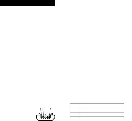
To check the computer AC Charger, do the following:
1.Disconnect the micro-USB cable from the tablet.
2.Measure the output voltage across the connector marked B of the micro-USB cable. Refer to the following figure:
1 2 |
3 (5V) |
Pin |
Voltage (V dc) |
|
|
1 |
Ground |
|
|
2 |
0 |
|
|
3 |
+5 |
Note: The output voltage across pin 3 of the micro-B connector might be different from the one you are servicing.
3.If the voltage is not correct, replace the micro-USB cable.
4.If the voltage is acceptable, replace the system board.
21
 Lenovo TAB 2 A10-30 Hardware Maintenance Manual
Checking the internal battery status
To check the battery status of the tablet, do either of the following:
•Approximate information about the battery status
Get the approximate status of the battery at any time by checking the battery status icon on the system bar in the upper-right corner of the screen. The shorter the green bar is, the less the battery power remains.
•Accurate information about the battery status
To get the accurate information about the battery status of the tablet, do the following:
1.Open the Android Settings screen.
To open the Android Settings screen, do either of the following:
–From the main Home screen, touch the Android Settings icon on Lenovo Launch Zone. The Android Settings screen is displayed.
–Pull down the application icon from the action bar and then touch Settings. The Android Settings screen is displayed.
2.Touch Battery in the Device section on the Android Settings screen.
3.The accurate percentage of the remaining battery power is shown on the screen.
22

Related service information
Related service information
This chapter presents the following information:
•“Security” on page 23
•“Power management” on page 23
Security
Security settings include: SCREEN SECURITY, SIM CARD LOCK (LTE version only), PASSWORDS, DEVICE ADMINISTRATION and CREDENTIAL STORAGE.
Power management
Note: Power management modes are not supported for APM operating system.
To reduce power consumption, the computer has three power management modes: screen blank, sleep (standby), and hibernation.
Activating/Deactivating the Display
With the display deactivated, press the Power button on the computer to activate the display. The computer display will then illuminate, indicating that it has been activated.
If you do not need to use your computer temporarily, you can press the Power button to deactivate the display. Your computer will then enter standby mode to save power.
23
 Loading...