


 Loading...
Lenovo 4272, 4271, 4269, 4266, 4265 User Manual
...ThinkStation
User Guide
Machine Types: 4262, 4263, 4264, 4265, 4266, 4269, 4271, and 4272
Note: Before using this information and the product it supports, be sure to read and understand the
ThinkStation Safety and Warranty Guide and Appendix B “Notices” on page 73.
Third Edition (December 2011)
© Copyright Lenovo 2010, 2011.
LIMITED AND RESTRICTED RIGHTS NOTICE: If data or software is delivered pursuant a General Services Administration “GSA” contract, use, reproduction, or disclosure is subject to restrictions set forth in Contract No. GS-35F-05925.

Contents
Important safety information . . . . . |
|
iii |
Chapter 1. Product overview . . . . . |
. |
1 |
Features . . . . . . . . . . . . . . . . . |
. |
1 |
Specifications . . . . . . . . . . . . . . . |
. |
3 |
Software overview . . . . . . . . . . . . . |
. |
4 |
Software provided with your Windows |
|
|
operating system . . . . . . . . . . . . |
. |
4 |
Locating computer controls, connectors, and |
|
|
parts . . . . . . . . . . . . . . . . . . |
. |
6 |
Locating controls and connectors on the front |
|
|
of your computer . . . . . . . . . . . . |
. |
6 |
Locating connectors on the rear of your |
|
|
computer . . . . . . . . . . . . . . . |
. |
7 |
Locating components . . . . . . . . . . |
. |
8 |
Locating parts and connectors on the system |
|
|
board . . . . . . . . . . . . . . . . |
. |
9 |
Chapter 2. Installing or replacing |
|
|
hardware . . . . . . . . . . . . . . . |
|
13 |
Installing or replacing hardware . . . . . . . . |
|
13 |
Installing external options . . . . . . . . |
|
13 |
Removing the computer cover. . . . . . . |
|
13 |
Removing and reinstalling the front bezel . . |
|
14 |
Removing and reinstalling the PCI card |
|
|
holder . . . . . . . . . . . . . . . . |
|
15 |
Installing or replacing a memory module . . . |
|
17 |
Installing or replacing a PCI card . . . . . . |
|
21 |
Installing a new hard disk drive . . . . . . |
|
23 |
Replacing a hard disk drive . . . . . . . . |
|
26 |
Replacing the optical drive . . . . . . . . |
|
27 |
Replacing the heat sink and fan assembly . . |
|
29 |
Replacing the front fan assembly . . . . . |
|
32 |
Replacing the rear fan assembly . . . . . . |
|
34 |
Replacing the keyboard or mouse . . . . . |
|
36 |
Completing the parts replacement . . . . . |
|
37 |
Obtaining device drivers . . . . . . . . . . . |
|
38 |
Basic security features . . . . . . . . . . . |
|
38 |
Locking devices . . . . . . . . . . . . |
|
39 |
Password protection . . . . . . . . . . |
|
40 |
Chapter 3. Recovery information . . . |
|
41 |
Creating and using recovery media . . . . . . |
|
41 |
Creating recovery media . . . . . . . . . |
|
41 |
Using recovery media . . . . . . . . . . |
|
41 |
Performing backup and recovery operations . . . |
|
42 |
Performing a backup operation . . . . . . |
|
43 |
Performing a recovery operation . . . . . . |
|
43 |
Using the Rescue and Recovery workspace . . . |
44 |
Creating and using a rescue medium . . . . . . |
45 |
Creating a rescue medium . . . . . . . . |
45 |
Using a rescue medium . . . . . . . . . |
45 |
Installing or reinstalling device drivers . . . . . |
46 |
Solving recovery problems . . . . . . . . . . |
46 |
Chapter 4. Using the Setup Utility |
|
program . . . . . . . . . . . . . . . . |
49 |
Starting the Setup Utility program . . . . . . . |
49 |
Viewing or changing settings . . . . . . . . . |
49 |
Using passwords. . . . . . . . . . . . . . |
49 |
Password considerations . . . . . . . . . |
50 |
Administrator password . . . . . . . . . |
50 |
User Password . . . . . . . . . . . . . |
50 |
Setting, changing, or deleting a password . . |
50 |
Enabling or disabling a device . . . . . . . . |
50 |
Selecting a startup device . . . . . . . . . . |
51 |
Selecting a temporary startup device . . . . |
51 |
Viewing or changing the startup device |
|
sequence . . . . . . . . . . . . . . . |
51 |
Advanced settings . . . . . . . . . . . . . |
52 |
Exiting the Setup Utility program . . . . . . . |
52 |
Chapter 5. Configuring RAID . . . . . |
53 |
Configuring RAID for machine types 4262, 4263, |
|
4264, and 4265 . . . . . . . . . . . . . . |
53 |
Installing SATA hard disk drives . . . . . . |
53 |
Configuring the system BIOS to enable SATA |
|
RAID functionality. . . . . . . . . . . . |
53 |
Creating RAID volumes . . . . . . . . . |
54 |
Deleting RAID volumes . . . . . . . . . |
54 |
Configuring RAID for machine types 4266, 4269, |
|
4271, and 4272 . . . . . . . . . . . . . . |
54 |
Installing SATA or SAS hard disk drives . . . |
55 |
Entering the Marvell BIOS Setup to configure |
|
SATA or SAS RAID . . . . . . . . . . . |
55 |
Configuring the Marvell BIOS Setup to enable |
|
SATA/SAS RAID 0, 1, or 5 functionality . . . |
55 |
Configuring the Marvell BIOS Setup to set an |
|
optional hot spare hard disk drive . . . . . |
56 |
Configuring the Marvell BIOS Setup to delete |
|
an optional hot spare hard disk drive . . . . |
56 |
Configuring the Marvell BIOS Setup to delete |
|
an array . . . . . . . . . . . . . . . |
56 |
Chapter 6. Updating system |
|
programs . . . . . . . . . . . . . . . |
57 |
Using system programs . . . . . . . . . . . |
57 |
© Copyright Lenovo 2010, 2011 |
i |
Updating (flashing) the BIOS from a disc . . . . |
57 |
Updating (flashing) the BIOS from your operating |
|
system . . . . . . . . . . . . . . . . . . |
58 |
Recovering from a POST/BIOS update failure . . |
58 |
Chapter 7. Troubleshooting and |
|
diagnostic programs . . . . . . . . . |
61 |
Basic troubleshooting . . . . . . . . . . . . |
61 |
Diagnostic programs . . . . . . . . . . . . |
62 |
Lenovo Solution Center . . . . . . . . . |
62 |
Lenovo ThinkVantage Toolbox . . . . . . . |
62 |
PC-Doctor for Rescue and Recovery . . . . |
63 |
PC-Doctor for DOS . . . . . . . . . . . |
63 |
Cleaning an optical mouse . . . . . . . . . . |
64 |
Chapter 8. Getting information, help, |
|
and service . . . . . . . . . . . . . . |
65 |
Information resources . . . . . . . . . . . . |
65 |
Online Books folder . . . . . . . . . . . |
65 |
Lenovo ThinkVantage Tools . . . . . . . . |
65 |
Lenovo Welcome . . . . . . . . . . . . |
65 |
Safety and warranty . . . . . . . . . . . |
66 |
Lenovo Web site (http://www.lenovo.com) . . |
66 |
Help and service . . . . . . . . . . . . . . |
66 |
Using the documentation and diagnostic |
|
programs . . . . . . . . . . . . . . . |
66 |
Calling for service. . . . . . . . . . . . |
66 |
Using other services . . . . . . . . . . |
67 |
Purchasing additional services . . . . . . |
68 |
Appendix A. System memory speed . |
69 |
Appendix B. Notices. . . . . . . . . . |
73 |
Television output notice . . . . . . . . . . . |
74 |
European conformance CE mark . . . . . . . |
74 |
Trademarks . . . . . . . . . . . . . . . . |
74 |
Index. . . . . . . . . . . . . . . . . . |
75 |
ii ThinkStation User Guide

Important safety information
CAUTION:
Before using this manual, be sure to read and understand all the related safety information for this product. Refer to the ThinkStation Safety and Warranty Guide that you received with this product for the latest safety information. Reading and understanding this safety information reduces the risk of personal injury and or damage to your product.
If you no longer have a copy of the ThinkCentre Safety and Warranty Guide, you can obtain a Portable Document Format (PDF) version from the Lenovo® Support Web site at http://support.lenovo.com.
© Copyright Lenovo 2010, 2011 |
iii |
iv ThinkStation User Guide

Chapter 1. Product overview
This chapter provides information about the computer features, specifications, preinstalled software programs, and connector and part locations.
This chapter contains the following topics:
•“Features” on page 1: This section provides information about the computer features.
•“Specifications” on page 3: This section lists the physical specifications for your computer.
•“Software overview” on page 4: This section provides information about the software programs provided with your computer.
•“Locating computer controls, connectors, and parts” on page 6: This section provides information to help you locate your computer controls, connectors, and parts.
Features
This section provides information about the computer features.
System information
The following information covers a variety of models. For information about your specific model, use the Setup Utility program. See Chapter 4 “Using the Setup Utility program” on page 49.
Microprocessor
Your computer comes with one of the following microprocessors (internal cache size varies by model type):
•Intel® Xeon® Dual Core microprocessor
•Intel Xeon Quad Core microprocessor
•Intel Xeon Six Core microprocessor
Memory module(s)
•Supports up to six or 12 double data rate 3 dual inline memory modules (DDR3 DIMMs)
•Each microprocessor supports up to three or six memory modules
Note: The Intel Xeon microprocessor families compatible with this ThinkStation™ computer feature an integrated memory controller, which provides the microprocessor with direct access to the system memory. Because of this design, the system memory speed will be determined by a number of factors, including the microprocessor model and the type, speed, size (capacity), and number of DIMMs installed. Refer to Appendix A “System memory speed” on page 69 for the information on the supported system memory speed for your computer model.
Internal drives
•One Serial Advanced Technology Attachment (SATA) optical drive
•Three SATA hard disk drives or Serial Attached SCSI (SAS) hard disk drives
Video subsystem
•Two Peripheral Component Interconnect (PCI) Express x16 card slots on the system board for discrete graphics cards (varies by model type)
© Copyright Lenovo 2010, 2011 |
1 |
Audio subsystem
•Integrated high-definition (HD) audio
•Microphone connector and headphone connector on the front panel
•Eight audio connectors on the rear panel
–Audio line-in connector
–Audio line-out front speaker connector
–Audio line-out rear speaker connector
–Audio line-out side speaker connector
–Audio line-out subwoofer/center speaker connector
–Microphone connector
–Optical Sony Philips Digital Interconnect Format (SPDIF) in connector
–Optical SPDIF out connector
•Internal speakers
Connectivity
• One or two 10/100/1000 Mbps Ethernet controller(s)
System management features
•Ability to store the power-on self-test (POST) hardware test results
•Advanced Configuration and Power Interface (ACPI) support
•Alert Standard Format (ASF) 2.0
•Automatic power-on startup
•Preboot Execution Environment (PXE)
•System Management (SM) Basic Input/Output System (BIOS) and SM software
•Wake on LAN
•Wake on Ring (in the Setup Utility program, this feature is called Serial Port Ring Detect for an external modem)
•Windows Management Instrumentation (WMI)
Input/Output (I/O) features
•9-pin serial port (available on some models)
•10 USB (Universal Serial Bus) connectors
•Eight audio connectors on the rear panel
•One external Serial Advanced Technology Attachment (eSATA) connector
•One or two Ethernet connector(s)
•Two audio connectors on the front panel (microphone connector and headphone connector)
•Two IEEE 1394 connectors (available on some models)
For more information about I/O features, see “Locating connectors on the rear of your computer” on page 7.
Expansion
•One optical drive bay
•One PCI Express x1 card slot
2 ThinkStation User Guide

•One PCI Express x4 card slot (x16 mechanical)
•Three hard disk drives
•Two PCI card slots
•Two PCI Express x16 card slots
Power supply
• 800-watt auto-sensing power supply
Security features
•Cover presence switch (also called intrusion switch) (available in some models)
•Enabling or disabling SATA devices
•Enabling or disabling the serial port
•Enabling or disabling USB connectors individually
•User password and administrator password to deter unauthorized use of your computer
•Startup sequence control
•Startup without keyboard or mouse
•Support for a keylock
•Support for the addition of a padlock
•Support for the addition of an integrated cable lock (Kensington lock)
•Trusted Platform Module (TPM)
Preinstalled software programs
Your computer is preinstalled with some software programs to help you work more easily and securely. For more information, see “Software overview” on page 4.
Preinstalled operating system
Your computer is preinstalled with one of the following operating systems:
•Microsoft® Windows® 7
•Microsoft Windows XP Professional (preinstalled through downgrade rights in Windows 7 Professional)
Operating system(s), certified or tested for compatibility1 (varies by model type)
• Linux®
Specifications
This section lists the physical specifications for your computer.
1.The operating system(s) listed here are being certified or tested for compatibility at the time this publication goes to press. Additional operating systems might be identified by Lenovo as compatible with your computer following the publication of this manual. This list is subject to change. To determine if an operating system has been certified or tested for compatibility, check the Web site of the operating system vendor.
Chapter 1. Product overview 3

Dimensions
Width: 130 mm (5.12 inches)
Height: 427 mm (16.81 inches)
Depth: 444 mm (17.48 inches)
Weight
Maximum configuration: 18.5 kg (40.8 lbs)
Environment
• Air temperature:
Operating: 10°C to 35°C (50°F to 95°F)
Storage: -10°C to 60°C (14°F to 140°F) without package
• Humidity:
Operating: 10% to 80% (10% per hour, non-condensing)
Storage: 10% to 90% (10% per hour, non-condensing)
• Maximum altitude: 7 000 ft (2 133.6 m)
Electrical input
•Input voltage:
– Low range:
Minimum: 100 V ac
Maximum: 127 V ac
Input frequency range: 50 to 60 Hz
– High range:
Minimum: 200 V ac
Maximum: 240 V ac
Input frequency range: 50 to 60 Hz
Software overview
The computer comes with a preinstalled operating system and several preinstalled applications.
Software provided with your Windows operating system
This section provides information about the software provided with your Windows operating system.
Software provided by Lenovo
The following software programs are provided by Lenovo to help you improve productivity and reduce the cost associated with maintaining your computer. Software programs provided with your computer might vary depending on your model type and preinstalled operating system.
Notes: The following software programs are supported on your ThinkStation computer. You can find detailed information and download the software programs from the Lenovo Support Web site at: http://support.lenovo.com
•ThinkVantage Productivity Center
•ThinkVantage Client Security Solution (CSS)
•ThinkVantage System Update (TVSU)
4 ThinkStation User Guide
Lenovo ThinkVantage Tools
The Lenovo ThinkVantage® Tools program guides you to a host of information sources and provides easy access to various tools to help you work more easily and securely. For more information, see “Lenovo ThinkVantage Tools” on page 65.
Note: The Lenovo ThinkVantage Tools program is only available on computers with the Windows 7 operating system from Lenovo.
Lenovo Welcome
The Lenovo Welcome program introduces some innovative built-in features of Lenovo to you and guides you through some important setup tasks to help you make the most of your computer.
Note: The Lenovo Welcome program is only available on computers preinstalled with the Windows 7 operating system from Lenovo.
Product Recovery
The Product Recovery program enables you to restore the contents of the hard disk drive to the factory default settings.
ThinkVantage Rescue and Recovery
The ThinkVantage Rescue and Recovery program is a one button recovery and restore solution that includes a set of self-recovery tools to help you diagnose computer problems, get help, and recover from system crashes, even if you cannot start the Windows operating system.
Lenovo Solution Center
Note: Depending on the date when your computer was manufactured, your computer is preinstalled with either the Lenovo Solution Center program or the Lenovo ThinkVantage Toolbox program for diagnostic purposes. For additional information about the Lenovo ThinkVantage Toolbox program, see “Lenovo ThinkVantage Toolbox” on page 62.
The Lenovo Solution Center program enables you to troubleshoot and resolve computer problems. It combines diagnostic tests, system information collection, security status, and support information, along with hints and tips for maximum system performance. See “Lenovo Solution Center” on page 62 for detailed information.
Lenovo ThinkVantage Toolbox
Note: Depending on the date when your computer was manufactured, your computer is preinstalled with either the Lenovo Solution Center program or the Lenovo ThinkVantage Toolbox program for diagnostic purposes. For additional information about the Lenovo Solution Center program, see “Lenovo Solution Center” on page 62.
The Lenovo ThinkVantage Toolbox program helps you maintain your computer, improve computing security, diagnose computer problems, get familiar with the innovative technologies provided by Lenovo, and get more information about your computer. For more information, see “Lenovo ThinkVantage Toolbox” on page 62.
PC-Doctor for Rescue and Recovery
The PC-Doctor for Rescue and Recovery diagnostic program is preinstalled on your ThinkStation computer as part of the Rescue and Recovery workspace to help you diagnose hardware problems. It can also report operating-system-controlled settings that interfere with the correct operation of your system. Use the PC-Doctor for Rescue and Recovery diagnostic program if you are unable to start the Windows operating system. For more information, see “PC-Doctor for Rescue and Recovery” on page 63.
Adobe Reader
The Adobe Reader program is a tool used to view, print, and search PDF documents.
Chapter 1. Product overview 5
See “Online Books folder” on page 65 for more information about accessing and viewing the publications.
Antivirus software
Your computer comes with antivirus software that you can use to detect and eliminate viruses. Lenovo provides a full version of antivirus software on your computer with a free 30-day subscription. After 30 days, you must renew the license to continue receiving the antivirus software updates.
For more information about how to use your antivirus software, refer to the help system of your antivirus software.
Locating computer controls, connectors, and parts
This section provides information to help you locate your computer controls, connectors, and parts.
Locating controls and connectors on the front of your computer
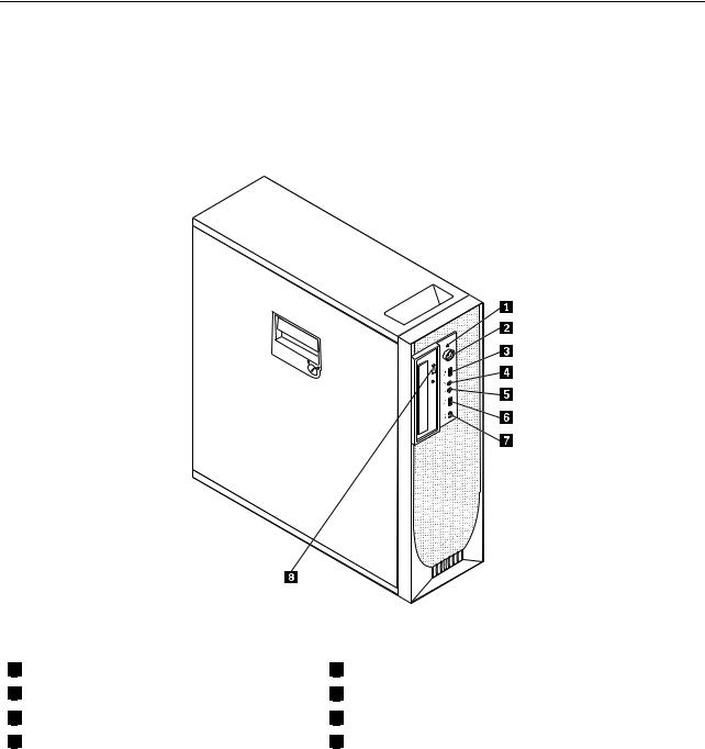
Figure 1 “Front control and connector locations” on page 6 shows the locations of the controls and connectors on the front of your computer.
Figure 1. Front control and connector locations
1 |
Hard disk drive activity indicator |
2 |
Power switch and power indicator |
3 |
USB connector |
4 |
Microphone connector |
5 |
Headphone connector |
6 |
USB connector |
7 |
IEEE 1394 connector (available on some models) |
8 |
Optical drive eject button |
6 ThinkStation User Guide
Locating connectors on the rear of your computer
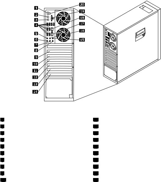
Figure 2 “Rear connector locations” on page 7 shows the locations of the connectors on the rear of your computer. Some connectors on the rear of your computer are color-coded to help you determine where to connect the cables on your computer.
Figure 2. Rear connector locations
1 eSATA connector
2 Optical SPDIF in connector
3 Optical SPDIF out connector
4 USB connectors (8)
5 Audio line-out side speaker connector
6 Microphone connector
7 Audio line-out front speaker connector
8 Audio line-in connector
9 PCI Express x1 card slot cover
10 PCI Express x16 card slot cover
11 |
PCI card slot cover |
12 |
PCI Express x16 card slot cover |
13 |
PCI Express x4 card slot cover |
14 |
PCI card slot cover |
15 |
Audio line-out subwoofer/center speaker connector |
16 |
Audio line-out rear speaker connector |
17 Ethernet connector (available on some models)
18 |
Ethernet connector |
19Serial port (available on some models)
20IEEE 1394 connector (available on some models)
Chapter 1. Product overview 7
Connector
Audio line-in connector
Audio line-out connector (front speaker connector)
Audio line-out connector (rear speaker connector)
Audio line-out connector (side speaker connector)
Audio line-out connector (subwoofer/center speaker connector)
eSATA connector
Ethernet connector
IEEE 1394 connector (available on some models)
Microphone connector
Optical SPDIF in connector
Optical SPDIF out connector
Serial port (available on some models)
USB connector
Description
Used to receive audio signals from an external audio device, such as a stereo system. When you attach an external audio device, a cable is connected between the audio line-out connector of the device and the audio line-in connector of the computer.
Used to send audio signals from the computer to external devices, such as powered stereo speakers (speakers with built-in amplifiers), multimedia keyboards, or the audio line-in connector on a stereo system or other external recording devices.
When used with 5.1 or 7.1 surround-sound speakers, this connector should be attached to the front left and right speakers.
When used with 5.1 or 7.1 surround-sound speakers, this connector should be attached to the rear left and right speakers.
When used with 7.1 surround-sound speakers, this connector should be attached to the side left and right speakers.
When used with 5.1 or 7.1 surround-sound speakers, this connector should be attached to the center speaker or subwoofer.
Use this connector to attach an external hard disk drive.
Used to attach an Ethernet cable for a local area network (LAN).
Notes:
1.To operate the computer within FCC Class B limits, use a Category 5 Ethernet cable.
2.If your computer has two Ethernet connectors, it is recommended that you connect your primary Ethernet cable to the Ethernet connector marked as number "1" for optimal performance.
Used to send and receive IEEE 1394 signals between the computer and a compliant device, such as a video camera or external storage drive. This connector is sometimes called FireWire because it transmits data rapidly.
Used to attach a microphone to your computer when you want to record sound or if you use speech-recognition software.
Used to receive 5.1 digital audio signals from an external device (such as a receiver or a multimedia device) through a TOSLINK (ToshibaLink) optical cable.
Used to send 5.1 digital audio signals from a computer to an external device (such as an amplifier or a receiver) through a TOSLINK optical cable.
Used to attach an external modem, a serial printer, or other devices that use a 9-pin serial port.
Used to attach a device that uses a USB connector, such as a USB keyboard, a USB mouse, a USB scanner, or a USB printer. If the USB connectors on your computer are not enough for you to connect all your USB devices, you can purchase a USB hub, which you can use to connect additional USB devices.
Locating components
Figure 3 “Component locations” on page 9 shows the locations of the various components in your computer. To remove the computer cover and access the inside of the computer, see “Removing the computer cover” on page 13.
8 ThinkStation User Guide
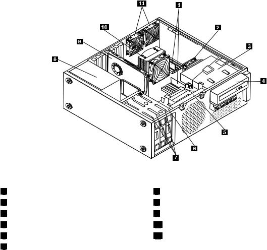
Figure 3. Component locations
1 |
Memory modules |
2 |
Heat sink and fan assembly 2 |
3 |
Optical drive bracket |
4 |
Optical drive |
5 |
Front fan assembly bracket |
6 |
Hard disk drive bay |
7 |
Hard disk drives (3) |
8 |
Power supply assembly |
9 |
PCI card |
10Heat sink and fan assembly 1
11Rear fan assemblies (2)
Locating parts and connectors on the system board
Note: Your computer comes with one of the following system boards.
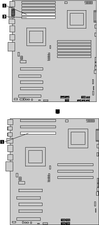
Figure 4 “System board part and connector locations” on page 10 shows the locations of the parts and connectors on one type of system board.
Chapter 1. Product overview 9

35
34
33
32 
31 
Figure 4. System board part and connector locations
1 |
CPU 1 memory slots (6) |
2 |
CPU 1 memory fan connector |
3 |
CPU 2 12 V power connector |
4 |
Microprocessor 2 |
5 |
24-pin power connector |
6 |
CPU 2 fan connector |
7 |
CPU 2 memory fan connector |
8 |
CPU 2 memory slots (6) |
9 |
Power switch and LEDs connector |
10Auxiliary LED connector
11Right rear fan connector
12Front fan connector
13Card reader connector
14Front USB connector
15Front IEEE 1394 connector
16Hard disk drive connectors (5)
17Optical drive connectors (3)
18Battery
19Clear Complementary Metal Oxide Semiconductor (CMOS) /Recovery jumper
20Thermal sensor connector
21Cover presence switch connector
22Personal System/2 (PS/2) keyboard and mouse connector
23Internal speaker connector
24Front audio connector
25PCI card slot
26 |
PCI Express x4 card slot (x16 mechanical) |
27 |
PCI Express x16 card slot |
28 |
PCI card slot |
29 |
PCI Express x16 card slot |
30 |
PCI Express x1 card slot |
31 |
Auxiliary 12 V power connector |
32 |
Left rear fan connector |
33 |
CPU 1 12 V power connector |
34 |
CPU 1 fan connector |
35 |
Microprocessor 1 |
10 ThinkStation User Guide
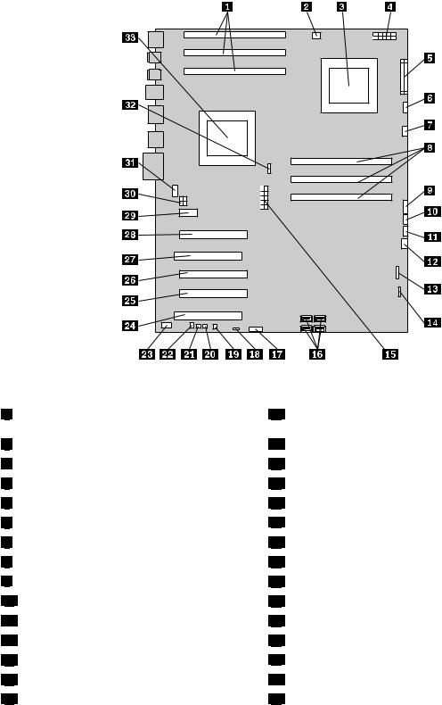
Figure 5 “System board part and connector locations” on page 11 shows the locations of the parts and connectors on the other type of system board.
Figure 5. System board part and connector locations
1 |
CPU 1 memory slots (3) |
2 |
CPU 1 memory fan connector |
3 |
Microprocessor 2 |
4 |
CPU 2 12 V power connector |
5 |
24-pin power connector |
6 |
CPU 2 fan connector |
7 |
CPU 2 memory fan connector |
8 |
CPU 2 memory slots (3) |
9 |
Power switch and LEDs connector |
10Auxiliary LED connector
11Right rear fan connector
12Front fan connector
13Card reader connector
14Front USB connector
15CPU 1 12 V power connector
18 Clear Complementary Metal Oxide Semiconductor (CMOS) /Recovery jumper
19 |
Thermal sensor connector |
20 |
Cover presence switch connector |
21 |
PS/2 keyboard and mouse connector |
22 |
Internal speaker connector |
23 |
Front audio connector |
24 |
PCI card slot |
25 PCI Express x4 card slot (x16 mechanical)
26 |
PCI Express x16 card slot |
27 |
PCI card slot |
28 |
PCI Express x16 card slot |
29 |
PCI Express x1 card slot |
30 |
Auxiliary 12 V power connector |
31 |
Left rear fan connector |
32 |
CPU 1 fan connector |
Chapter 1. Product overview 11

16 |
SATA connectors (4) |
17 |
Battery |
33 |
Microprocessor 1 |
12 ThinkStation User Guide

Chapter 2. Installing or replacing hardware
This chapter provides instructions on how to install or replace hardware for your computer.
This chapter contains the following topics:
•“Installing or replacing hardware” on page 13
•“Obtaining device drivers” on page 38
•“Basic security features” on page 38
Installing or replacing hardware
This section provides instructions on how to install or replace hardware for your computer. You can maintain your computer or expand the capabilities of your computer by installing or replacing hardware.
Notes:
1.Use only computer parts provided by Lenovo.
2.When installing or replacing an option, use the appropriate instructions in this section along with the instructions that come with the option.
Installing external options
You can install external options to your computer, such as external speakers, a printer, or a scanner. For some external options, you must install additional software in addition to making the physical connection. When you install an external option, see “Locating computer controls, connectors, and parts” on page 6 to identify the required connector. Then, use the instructions that come with the option to help you make the connection and install any software or device drivers that are required for the option.
Removing the computer cover
Attention: Do not open your computer or attempt any repair before reading and understanding the “Important safety information” in the ThinkStation Safety and Warranty Guide that came with your computer. To obtain a copy of the
ThinkStation Safety and Warranty Guide, go to: http://support.lenovo.com
This section provides instructions on how to remove the computer cover.
CAUTION:
The heat sink and fan assembly might be very hot. Turn off the computer and wait three to five minutes to let the computer cool before removing the computer cover.
To remove the computer cover, do the following:
1.Remove all media from the drives and turn off all attached devices and the computer. Then, disconnect all power cords from electrical outlets and disconnect all cables that are connected to the computer.
© Copyright Lenovo 2010, 2011 |
13 |
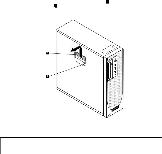
2.Use the keys that came with your computer to unlock the keylock 1 in the computer cover. Press the computer cover-release button 2 and then remove the computer cover. Place the computer cover on a flat surface.
Figure 6. Removing the computer cover
Removing and reinstalling the front bezel
Attention: Do not open your computer or attempt any repair before reading and understanding the “Important safety information” in the ThinkStation Safety and Warranty Guide that came with your computer. To obtain a copy of the
ThinkStation Safety and Warranty Guide, go to: http://support.lenovo.com
This section provides instructions on how to remove and reinstall the front bezel.
To remove and reinstall the front bezel, do the following:
1.Remove all media from the drives and turn off all attached devices and the computer. Then, disconnect all power cords from electrical outlets and disconnect all cables that are connected to the computer.
2.Remove the computer cover. See “Removing the computer cover” on page 13.
14 ThinkStation User Guide
3.Remove the front bezel by releasing the two plastic tabs on the left side and pivoting the front bezel outward.
Figure 7. Removing the front bezel
4.Lay the front bezel on a flat surface.
5.To reinstall the front bezel, align the other three plastic tabs on the right side of the front bezel with the corresponding holes in the chassis, then pivot the front bezel inward until it snaps into position.
Removing and reinstalling the PCI card holder
Attention: Do not open your computer or attempt any repair before reading and understanding the “Important safety information” in the ThinkStation Safety and Warranty Guide that came with your computer. To obtain a copy of the
ThinkStation Safety and Warranty Guide, go to: http://support.lenovo.com
This section provides instructions on how to remove and reinstall the PCI card holder.
To remove and reinstall the PCI card holder, do the following:
1.Remove all media from the drives and turn off all attached devices and the computer. Then, disconnect all power cords from electrical outlets and disconnect all cables that are connected to the computer.
2.Remove the computer cover. See “Removing the computer cover” on page 13.
3.Remove the front bezel. See “Removing and reinstalling the front bezel” on page 14.
4.Lay the computer on its side.
Chapter 2. Installing or replacing hardware 15
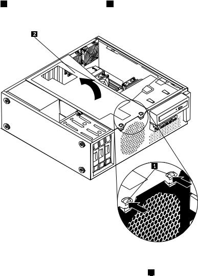
5.Press the two tabs 1 that secure the PCI card holder 2 inward, and then pivot the card holder to remove it from the chassis.
Figure 8. Removing the PCI card holder
6.To reinstall the PCI card holder into the chassis, insert the two tabs 1 into the corresponding holes in the chassis, and then pivot the PCI card holder downward until the front of the card holder snaps into position.
16 ThinkStation User Guide
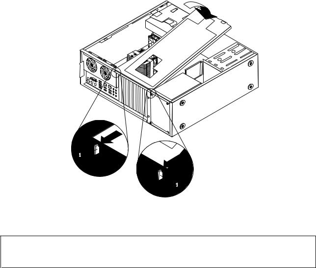
Figure 9. Installing the PCI card holder
Installing or replacing a memory module
Attention: Do not open your computer or attempt any repair before reading and understanding the “Important safety information” in the ThinkStation Safety and Warranty Guide that came with your computer. To obtain a copy of the
ThinkStation Safety and Warranty Guide, go to: http://support.lenovo.com
This section provides instructions on how to install or replace a memory module.
Depending on your model, your computer has six or 12 slots for installing or replacing DDR3 ECC UDIMMs (double data rate 3 error correction code unbuffered dual in-line memory modules) or DDR3 ECC RDIMMs (double data rate 3 error correction code registered dual in-line memory modules). See “Locating parts and connectors on the system board” on page 9.
When installing or replacing memory modules, use the following guidelines:
•Use either DDR3 ECC UDIMMs or DDR3 ECC RDIMMs for your computer. Do not install both the UDIMMs and RDIMMs into the same computer.
•Use 1 GB, 2 GB, or 4 GB UDIMMs in any combination up to a maximum of 24 GB or 48 GB of system memory.
•Use 1 GB, 2 GB, 4 GB, 8 GB, or 16 GB RDIMMs in any combination up to a maximum of 96 GB or 192 GB of system memory.
•Always install DIMMs in the numerical order printed on the system board (DIMM1, DIMM2, DIMM3, and so on). Install memory modules into the blue memory slots first.
Chapter 2. Installing or replacing hardware 17
•If your computer has only one CPU installed, be sure to install memory modules only in the memory slots adjacent to that CPU.
•If your computer has two CPUs installed, install equal numbers of memory modules in both sets of CPU DIMM slots for maximum performance.
To install or replace a memory module, do the following:
1.Remove all media from the drives and turn off all attached devices and the computer. Then, disconnect all power cords from electrical outlets and disconnect all cables that are connected to the computer.
2.Remove the computer cover. See “Removing the computer cover” on page 13.
3.Remove the PCI card holder. See “Removing and reinstalling the PCI card holder” on page 15.
4.Locate the memory slots. See “Locating parts and connectors on the system board” on page 9.
5.Depending on the memory module that you are replacing, do one of the following:
•If you are replacing the memory module adjacent to CPU 1, go to step 6.
•If you are replacing the memory module adjacent to CPU 2, do the following:
a.Remove the optical drive. See “Replacing the optical drive” on page 27.
b.Pivot the optical drive bracket as shown in the following illustration and then remove it from the chassis. Go to step 6.
Figure 10. Removing the optical drive bracket
6.For some computer models, you might need to remove the memory fan duct to access the memory slots. To remove the memory fan duct, disconnect the memory fan cable from the system board, remove the blue shipping clip, press inward on the two tabs 1 , pivot the fan duct, and then disengage the rear of the fan duct.
Note: Not all computer models have the memory fan duct and blue shipping clip.
18 ThinkStation User Guide
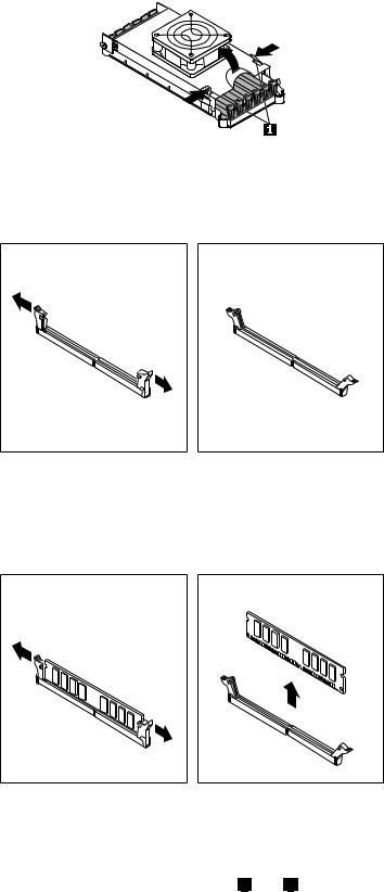
Figure 11. Removing the memory fan duct
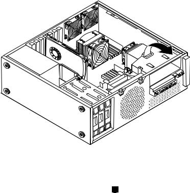
7. Open the retaining clips as shown.
Figure 12. Opening the retaining clips
If you are replacing an old memory module, open the retaining clips and gently pull the memory module out of the memory slot.
Figure 13. Removing a memory module
Notes:
a.If your computer has 12 memory slots on the system board, you might have to use more force to remove the memory modules installed in memory slots 1 and 2 .
Chapter 2. Installing or replacing hardware 19
b.If your computer has six memory slots on the system board, you might have to use more force to remove the memory module installed in memory slot 1 .
20 ThinkStation User Guide
Loading...