


8099
Table of contents
 Loading...
Lenovo 8099, 9211, 9210, 8214, 8215 Service Manual
...
Hardw are Maintenance Man ual
Types 8099, 8110, 8111, 8112, 8113, 8114
Types 8115, 8116, 8153, 8154, 8155, 8156
Types 8157, 8158, 8159, 8160, 8161, 8162
Types 8163, 8165, 8166, 8167, 8168, 8169
Types 8170, 8211, 8212, 8213, 8214, 8215
Types 9210, 9211


Hardw are Maintenance Man ual

Note: Before using this information and the product it supports, be sure to read the
information under “Notices,” on page 521.
Fourteenth Edition (May 2009)
© Copyright Lenovo 2005, 2009.
Portions © Copyright International Business Machines Corporation 2005.
LENOVO products, data, computer software, and services have been developed exclusively at private expense and
are sold to governmental entities as commercial items as defined by 48 C.F.R. 2.101 with limited and restricted
rights to use, reproduction and disclosure.
LIMITED AND RESTRICTED RIGHTS NOTICE: If products, data, computer software, or services are delivered
pursuant a General Services Administration ″GSA″ contract, use, reproduction, or disclosure is subject to restrictions
set forth in Contract No. GS-35F-05925.

Contents
Chapter 1. About this manual .....1
Important Safety Information .........1
Strategy for replacing FRUs for CTO, CMV, and GAV
products................2
Product definition ...........2
FRU Identification for CTO, CMV, and GAV
products...............2
Important information about replacing RoHS
compliant FRUs .............3
Chapter 2. Safety information .....5
General safety ..............5
Electrical safety .............5
Safety inspection guide ...........7
Handling electrostatic discharge-sensitive devices . . 8
Grounding requirements ..........8
Safety notices (multi-lingual translations) .....9
Chapter 3. General information ....39
Additional information resources .......39
Physical specifications ...........39
Types 8099, 8116, 8155, 8156, 8157, 8158, 8159,
8160, 8215, 9210, and 9211 ........40
Types 8110, 8112, 8113, 8114, 8115, 8153, 8166,
8167, 8168, 8169, and 8170 ........41
Types 8111, 8154, 8161, 8162, 8163, 8165, 8211,
8212, 8213, and 8214 ..........42
Chapter 4. General Checkout .....43
Problem determination tips .........44
Chapter 5. Diagnostics using
PC-Doctor for DOS .........47
Starting PC-Doctor from the Rescue and Recovery
workspace...............47
Starting PC-Doctor from a diagnostic diskette or
CD-ROM ...............48
Diagnostics program download........48
Navigating through the diagnostics programs . . . 48
Running diagnostics tests..........48
Test selection .............49
Test results .............49
Fixed disk advanced test (FDAT) ......49
Quick and Full erase - hard drive ......51
Viewing the test log ...........52
Chapter 6. Using the Setup Utility . . . 53
Starting the Setup Utility program .......53
Viewing and changing settings ........53
Exiting from the Setup Utility program .....53
Using passwords ............53
Password considerations .........54
User Password ............54
Administrator Password .........54
IDE Drive User Password ........54
IDE Drive Master Password ........54
Setting, changing, and deleting a password. . . 55
Using Security Profile by Device .......55
Selecting a startup device..........56
Selecting a temporary startup device .....56
Changing the startup device sequence ....56
Advanced settings ............56
Chapter 7. Symptom-to-FRU Index . . . 57
Hard disk drive boot error .........57
Power Supply Errors ...........57
Diagnostic error codes ...........59
Beep symptoms .............80
No-beep symptoms............82
POST error codes ............83
Miscellaneous error messages ........86
Undetermined problems ..........88
Chapter 8. FRU lists .........89
Machine Type 8099 ............90
Machine Type 8110 ...........109
Machine Type 8111 ...........125
Machine Type 8112 ...........141
Machine Type 8113 ...........155
Machine Type 8114 ...........182
Machine Type 8115 ...........199
Machine Type 8116 ...........213
Machine Type 8153 ...........228
Machine Type 8154 ...........236
Machine Type 8155 ...........244
Machine Type 8156 ...........253
Machine Type 8157 ...........261
Machine Type 8158 ...........270
Machine Type 8159 ...........280
Machine Type 8160 ...........288
Machine Type 8161 ...........297
Machine Type 8162 ...........305
Machine Type 8163 ...........313
Machine Type 8164 ...........321
Machine Type 8165 ...........329
Machine Type 8166 ...........337
Machine Type 8167 ...........343
Machine Type 8168 ...........350
Machine Type 8169 ...........361
Machine Type 8170 ...........368
Machine Type 8211 ...........375
Machine Type 8212 ...........390
Machine Type 8213 ...........417
Machine Type 8214 ...........436
Machine Type 8215 ...........452
Machine Type 9210 ...........479
Machine Type 9211 ...........498
© Lenovo 2005, 2009. Portions © IBM Corp. 2005. iii

Chapter 9. Additional Service
Information ............515
Security features ............515
Hardware controlled Passwords ......515
Operating system password .......515
Vital product data ...........515
Management Information Format (MIF) . . . 515
BIOS levels ..............516
Flash update procedures..........516
Updating (flashing) BIOS from a diskette or
CD-ROM ..............516
Updating (flashing) BIOS from your operating
system ..............516
Recovering from a POST/BIOS update failure 517
Power management ...........518
Automatic configuration and power interface
(ACPI) BIOS.............518
Automatic Power-On features .......518
Recovering software using the Rescue and
Recovery program............519
Starting the Rescue and Recovery workspace 519
Appendix. Notices .........521
Television output notice ..........522
Trademarks ..............522
iv Hardware Maintenance Manual

Chapter 1. About this manual
This manual contains service and reference information for ThinkCentre
®
computers listed on the cover. It is intended only for trained servicers who are
familiar with Lenovo
®
computer products.
Before servicing a Lenovo product, be sure to read the Safety Information. See
Chapter 2, “Safety information,” on page 5.
The Symptom-to-FRU Index and Additional Service Information chapters are not
specific to any machine type and are applicable to all ThinkCentre computers.
This manual includes a complete FRU part number listing for each machine type
and model listed on the cover. If you have internet access, FRU part numbers are
also available at:
http:/www.lenovo.com/support
This manual does not include procedures for replacing FRUs. For FRU replacement
procedures, refer to the Hardware Replacement Guide for the appropriate machine
type. The Hardware Replacement Guide is available at:
http:/www.lenovo.com/support.
Important Safety Information
Be sure to read all caution and danger statements in this book before performing
any of the instructions.
Veuillez lire toutes les consignes de type DANGER et ATTENTION du présent
document avant d’exécuter les instructions.
Lesen Sie unbedingt alle Hinweise vom Typ ″ACHTUNG″ oder ″VORSICHT″ in
dieser Dokumentation, bevor Sie irgendwelche Vorgänge durchführen
Leggere le istruzioni introdotte da ATTENZIONE e PERICOLO presenti nel
manuale prima di eseguire una qualsiasi delle istruzioni
Certifique-se de ler todas as instruções de cuidado e perigo neste manual antes de
executar qualquer uma das instruções
Es importante que lea todas las declaraciones de precaución y de peligro de este
manual antes de seguir las instrucciones.
© Lenovo 2005, 2009. Portions © IBM Corp. 2005. 1

Strategy for replacing FRUs for CTO, CMV, and GAV products
Product definition
Dynamic Configure To Order (CTO)
This provides the ability for a customer to configure a Lenovo solution
from an eSite, and have this configuration sent to fulfillment, where it is
built and shipped directly to the customer. The machine label, PC
Entitlement Warehouse (PEW), eSupport, and the HMM will include these
products as the 4-digit machine type (MT) and 3-digit model, where model
= ’CTO’ (Example: 8129-CTO).
Custom Model Variant (CMV)
This is a unique configuration that has been negotiated between Lenovo
and the customer. A unique 4-digit MT and 3-digit model is provided to
the customer to place orders (Example: 8129-W15). A CMV is a special bid
offering. Therefore, it is NOT generally announced.
v The machine type model (MTM) portion of the machine label is the
4-digit MT and 3-digit model, where model = ’CTO’ (Example:
8129-CTO). The PRODUCT ID portion of the machine label is the 4-digit
MT and 3-digit CMV model (Example: 8129-W15).
v The PEW record is the 4-digit MT and 3-digit model, where model =
’CTO’ (Example: 8129-CTO).
v eSupport will show both the CTO and CMV machine type models
(Example: 8129-CTO and 8129-W15 will be found on the eSupport site.)
v The HMM will have the 4-digit MT and 3-digit CTO model only
(Example: 8129-CTO). Again, CMVs are custom models and are not
found in the HMM.
General Announce Variant (GAV)
This is a standard model (fixed configuration). GAVs are announced and
offered to all customers. The MTM portion of the machine label is a 4-digit
MT and 3-digit model, where model = a “fixed model number”, not ’CTO’
(Example: 8129-F1U). Also, PEW, eSupport, and the HMM will list these
products under the same fixed model number.
FRU Identification for CTO, CMV, and GAV products
There are three information resources to identify which FRUs are used to support
CTO, CMV, and GAV products. These sources are PEW, eSupport, and the HMM.
Using PEW
v PEW is the primary source for identifying FRU part numbers and FRU
descriptions for the key commodities for CTO, CMV and GAV products at a MT
- serial number level. An example of key commodities are hard disk drives,
system boards, microprocessors, Liquid Crystal Displays (LCDs), and memory.
v Remember, All CTO and CMV products are loaded in PEW under the 4-digit
MT and 3-digit model, where model = ’CTO’ (Example: 8129-CTO). GAVs are
loaded in PEW under the 4-digit MT and 3-digit model, where model = a “fixed
model number”, not ’CTO’ (Example: 8129-F1U).
v PEW can be accessed as follows:
1. Point your browser to http://w3-3.ibm.com/pc/entitle.
2. Under PEW Home, click Machine Lookup.
2 Hardware Maintenance Manual

3. Under Machine Lookup, click Warranty Information.
4. Under Warranty Information, type the MT and Serial number and click
Submit.
The list of key commodities is returned in the PEW record under Component
Information.
v Business Partners using Eclaim will access PEW when performing Entitlement
Lookup. Business Partners will enter Loc ID, MT and Serial, and the key
commodities will be returned in the Eclaim record under System Details.
v Authorized Lenovo Business Partners can access Eclaim at the following Web
site:
http://wca.eclaim.com
Using eSupport
For Key Commodities (Examples - hard disk drive, system board,
microprocessor, LCD, and memory)
v eSupport can be used to view the list of key commodities built in a particular
machine serial (this is the same record found in PEW).
v eSupport can be accessed at the following Web site:
http://www.lenovo.com/support
v To view the key commodities:
1. Click Parts information.
2. Under Parts information, click Parts lookup.
3. Under Parts lookup, type the model type and serial number; then click
Continue.
The key commodities are returned in the eSupport record under Parts
shipped with your system.
For the remaining FRUs (the complete list of FRUs at the MT Model level)
v eSupport can be used to view the complete list of FRUs for a machine type and
model.
v To view the complete list of FRUs for a machine type:
1. Point your browser to http://www.lenovo.com/support.
2. Type the machine type (Example: 8129) in the Use Quick Path field; then
click Go.
3. Under Browse by product, click Continue.
4. Under Important information, click Parts information.
5. In the Refine results field, select Service parts; then click the entry for your
machine type.
The list of service parts by description, with applicable machine type model
and FRU part number is displayed.
Using the HMM
v Use the HMM as a back-up to PEW and eSupport to view the complete list of
FRU part numbers at the MT Model level.
Important information about replacing RoHS compliant FRUs
RoHS, The Restriction of Hazardous Substances in Electrical and Electronic
Equipment Directive (2002/95/EC) is a European Union legal requirement
affecting the global electronics industry. RoHS requirements must be
implemented on Lenovo products placed on the market after June 2006. Products
on the market before June 2006 are not required to have RoHS compliant parts.
Chapter 1. About this manual 3
So, if the parts are not compliant originally, replacement parts can also be
noncompliant, but in all cases, if the parts are compliant, the replacement parts
must also be compliant.
Lenovo plans to transition to RoHS compliance well before the implementation
date and expects its suppliers to be ready to support Lenovo’s requirements and
schedule. Products sold in 2005, will contain some RoHS compliant FRUs. The
following statement pertains to these products and any product Lenovo produces
containing RoHS compliant parts.
RoHS compliant ThinkCentre parts have unique FRU part numbers. Before or after
June, 2006, failed RoHS compliant parts must always be replaced using RoHS
compliant FRUs, so only the FRUs identified as compliant in the system HMM or
direct substitutions for those FRUs can be used.
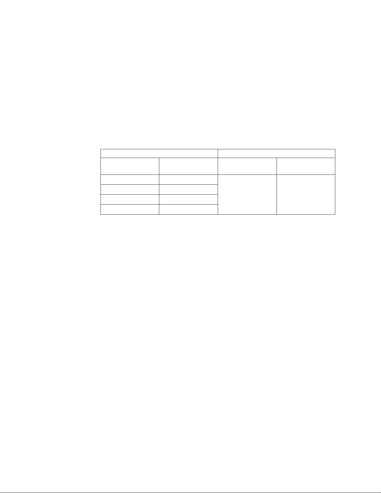
Products marketed before June 2006 Products marketed after June 2006
Current or original
part
Replacement FRU Current or original
part
Replacement FRU
Non-RoHS Can be Non-RoHS Must be RoHS Must be RoHS
Non-RoHS Can be RoHS
Non-RoHS Can sub to RoHS
RoHS Must be RoHS
Note: A direct substitution is a part with a different FRU part number that is
automatically shipped by the distribution center at the time of order.
Related Web URLs are:
v Lenovo information for Suppliers website:
http://www-03.ibm.com/procurement/proweb.nsf/ContentDocsByTitle/
United+States~Information+for+suppliers
v RoHS Directive:
http://europa.eu.int/eur-lex/pri/en/oj/dat/2003/l_037/
l_03720030213en00190023.pdf
v California Senate Bills 20, 50:
http://www.ciwmb.ca.gov/HHW/Events/AnnualConf/2004/
presentation/MPaparian.pdf
4 Hardware Maintenance Manual

Chapter 2. Safety information
This chapter contains the safety information that you need to be familiar with
before servicing a computer.
General safety
Follow these rules to ensure general safety:
v Observe good housekeeping in the area of the machines during and after
maintenance.
v When lifting any heavy object:
1. Ensure you can stand safely without slipping.
2. Distribute the weight of the object equally between your feet.
3. Use a slow lifting force. Never move suddenly or twist when you attempt to
lift.
4. Lift by standing or by pushing up with your leg muscles; this action removes
the strain from the muscles in your back. Do not attempt to lift any objects that
weigh more than 16 kg (35 lb) or objects that you think are too heavy for you.
v Do not perform any action that causes hazards to the customer, or that makes
the equipment unsafe.
v Before you start the machine, ensure that other service representatives and the
customer’s personnel are not in a hazardous position.
v Place removed covers and other parts in a safe place, away from all personnel,
while you are servicing the machine.
v Keep your tool case away from walk areas so that other people will not trip over
it.
v Do not wear loose clothing that can be trapped in the moving parts of a
machine. Ensure that your sleeves are fastened or rolled up above your elbows.
If your hair is long, fasten it.
v Insert the ends of your necktie or scarf inside clothing or fasten it with a
nonconductive clip, approximately 8 centimeters (3 inches) from the end.
v Do not wear jewelry, chains, metal-frame eyeglasses, or metal fasteners for your
clothing.
Remember: Metal objects are good electrical conductors.
v Wear safety glasses when you are: hammering, drilling soldering, cutting wire,
attaching springs, using solvents, or working in any other conditions that might
be hazardous to your eyes.
v After service, reinstall all safety shields, guards, labels, and ground wires.
Replace any safety device that is worn or defective.
v Reinstall all covers correctly before returning the machine to the customer.
Electrical safety
© Lenovo 2005, 2009. Portions © IBM Corp. 2005. 5

CAUTION:
Electrical current from power, telephone, and communication cables can be
hazardous. To avoid personal injury or equipment damage, disconnect the
attached power cords, telecommunication systems, networks, and modems before
you open the server/workstation covers, unless instructed otherwise in the
installation and configuration procedures.
Observe the following rules when working on electrical equipment.
Important: Use only approved tools and test equipment. Some hand tools have
handles covered with a soft material that does not insulate you when
working with live electrical currents.
Many customers have, near their equipment, rubber floor mats that
contain small conductive fibers to decrease electrostatic discharges. Do
not use this type of mat to protect yourself from electrical shock.
v Find the room emergency power-off (EPO) switch, disconnecting switch, or
electrical outlet. If an electrical accident occurs, you can then operate the switch
or unplug the power cord quickly.
v Do not work alone under hazardous conditions or near equipment that has
hazardous voltages.
v Disconnect all power before:
– Performing a mechanical inspection
– Working near power supplies
– Removing or installing main units
v Before you start to work on the machine, unplug the power cord. If you cannot
unplug it, ask the customer to power-off the wall box that supplies power to the
machine and to lock the wall box in the off position.
v If you need to work on a machine that has exposed electrical circuits, observe
the following precautions:
– Ensure that another person, familiar with the power-off controls, is near you.
Remember: Another person must be there to switch off the power, if
necessary.
– Use only one hand when working with powered-on electrical equipment;
keep the other hand in your pocket or behind your back.
Remember: There must be a complete circuit to cause electrical shock. By
observing the above rule, you may prevent a current from passing through
your body.
– When using testers, set the controls correctly and use the approved probe
leads and accessories for that tester.
– Stand on suitable rubber mats (obtained locally, if necessary) to insulate you
from grounds such as metal floor strips and machine frames.
Observe the special safety precautions when you work with very high voltages;
these instructions are in the safety sections of maintenance information. Use
extreme care when measuring high voltages.
v Regularly inspect and maintain your electrical hand tools for safe operational
condition.
v Do not use worn or broken tools and testers.
v Never assume that power has been disconnected from a circuit. First, check that it
has been powered-off.
6 Hardware Maintenance Manual

v Always look carefully for possible hazards in your work area. Examples of these
hazards are moist floors, nongrounded power extension cables, power surges,
and missing safety grounds.
v Do not touch live electrical circuits with the reflective surface of a plastic dental
mirror. The surface is conductive; such touching can cause personal injury and
machine damage.
v Do not service the following parts with the power on when they are removed
from their normal operating places in a machine:
– Power supply units
– Pumps
– Blowers and fans
– Motor generators
and similar units. (This practice ensures correct grounding of the units.)
v If an electrical accident occurs:
– Use caution; do not become a victim yourself.
– Switch off power.
– Send another person to get medical aid.
Safety inspection guide
The intent of this inspection guide is to assist you in identifying potentially unsafe
conditions on these products. Each machine, as it was designed and built, had
required safety items installed to protect users and service personnel from injury.
This guide addresses only those items. However, good judgment should be used to
identify potential safety hazards due to attachment of features or options not
covered by this inspection guide.
If any unsafe conditions are present, you must determine how serious the apparent
hazard could be and whether you can continue without first correcting the
problem.
Consider these conditions and the safety hazards they present:
v Electrical hazards, especially primary power (primary voltage on the frame can
cause serious or fatal electrical shock).
v Explosive hazards, such as a damaged CRT face or bulging capacitor
v Mechanical hazards, such as loose or missing hardware
The guide consists of a series of steps presented in a checklist. Begin the checks
with the power off, and the power cord disconnected.
Checklist:
1. Check exterior covers for damage (loose, broken, or sharp edges).
2. Power-off the computer. Disconnect the power cord.
3. Check the power cord for:
a. A third-wire ground connector in good condition. Use a meter to measure
third-wire ground continuity for 0.1 ohm or less between the external
ground pin and frame ground.
b. The power cord should be the appropriate type as specified in the parts
listings.
c. Insulation must not be frayed or worn.
4. Remove the cover.
Chapter 2. Safety information 7

5. Check for any obvious alterations. Use good judgment as to the safety of any
alterations.
6. Check inside the unit for any obvious unsafe conditions, such as metal filings,
contamination, water or other liquids, or signs of fire or smoke damage.
7. Check for worn, frayed, or pinched cables.
8. Check that the power-supply cover fasteners (screws or rivets) have not been
removed or tampered with.
Handling electrostatic discharge-sensitive devices
Any computer part containing transistors or integrated circuits (ICs) should be
considered sensitive to electrostatic discharge (ESD). ESD damage can occur when
there is a difference in charge between objects. Protect against ESD damage by
equalizing the charge so that the machine, the part, the work mat, and the person
handling the part are all at the same charge.
Notes:
1. Use product-specific ESD procedures when they exceed the requirements noted
here.
2. Make sure that the ESD protective devices you use have been certified (ISO
9000) as fully effective.
When handling ESD-sensitive parts:
v Keep the parts in protective packages until they are inserted into the product.
v Avoid contact with other people.
v Wear a grounded wrist strap against your skin to eliminate static on your body.
v Prevent the part from touching your clothing. Most clothing is insulative and
retains a charge even when you are wearing a wrist strap.
v Use the black side of a grounded work mat to provide a static-free work surface.
The mat is especially useful when handling ESD-sensitive devices.
v Select a grounding system, such as those listed below, to provide protection that
meets the specific service requirement.
Note: The use of a grounding system is desirable but not required to protect
against ESD damage.
– Attach the ESD ground clip to any frame ground, ground braid, or green-wire
ground.
– Use an ESD common ground or reference point when working on a
double-insulated or battery-operated system. You can use coax or
connector-outside shells on these systems.
– Use the round ground-prong of the ac plug on ac-operated computers.
Grounding requirements
Electrical grounding of the computer is required for operator safety and correct
system function. Proper grounding of the electrical outlet can be verified by a
certified electrician.
8 Hardware Maintenance Manual
Safety notices (multi-lingual translations)
The caution and danger safety notices in this section are provided in the following
languages:
v English
v Arabic
v Brazilian/Portuguese
v Chinese (simplified)
v Chinese (traditional)
v French
v German
v Hebrew
v Italian
v Korean
v Spanish
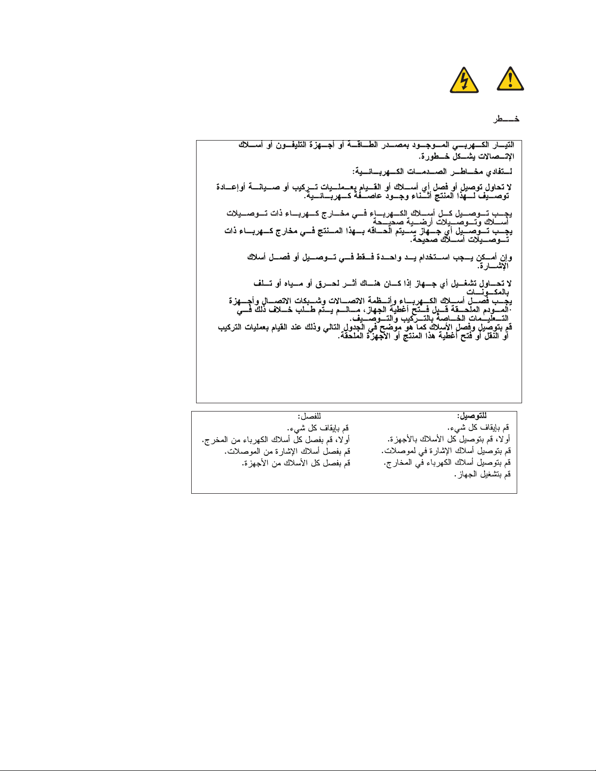
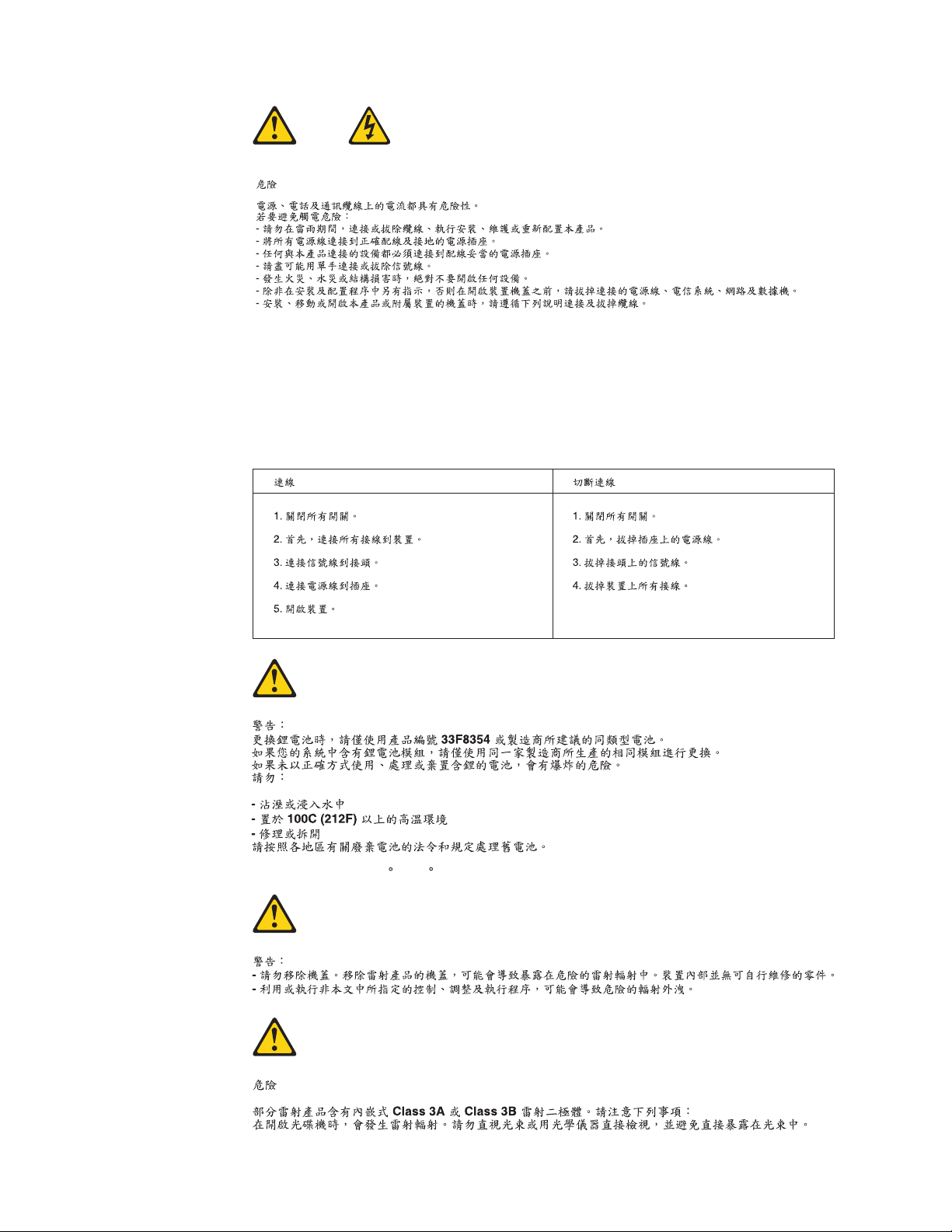
DANGER
Electrical current from power, telephone and communication cables is hazardous.
To avoid a shock hazard:
v Do not connect or disconnect any cables or perform installation, maintenance,
or reconfiguration of this product during an electrical storm.
v Connect all power cords to a properly wired and grounded electrical outlet.
v Connect to properly wired outlets any equipment that will be attached to this
product.
v When possible, use one hand only to connect or disconnect signal cables.
v Never turn on any equipment when there is evidence of fire, water, or
structural damage.
v Disconnect the attached power cords, telecommunications systems, networks,
and modems before you open the device covers, unless instructed otherwise
in the installation and configuration procedures.
v Connect and disconnect cables as described in the following table when
installing, moving, or opening covers on this product or attached devices.
To Connect To Disconnect
1. Turn everything OFF.
2. First, attach all cables to devices.
3. Attach signal cables to connectors.
4. Attach power cords to outlet.
5. Turn device ON.
1. Turn everything OFF.
2. First, remove power cords from outlet.
3. Remove signal cables from connectors.
4. Remove all cables from devices.
Chapter 2. Safety information 9
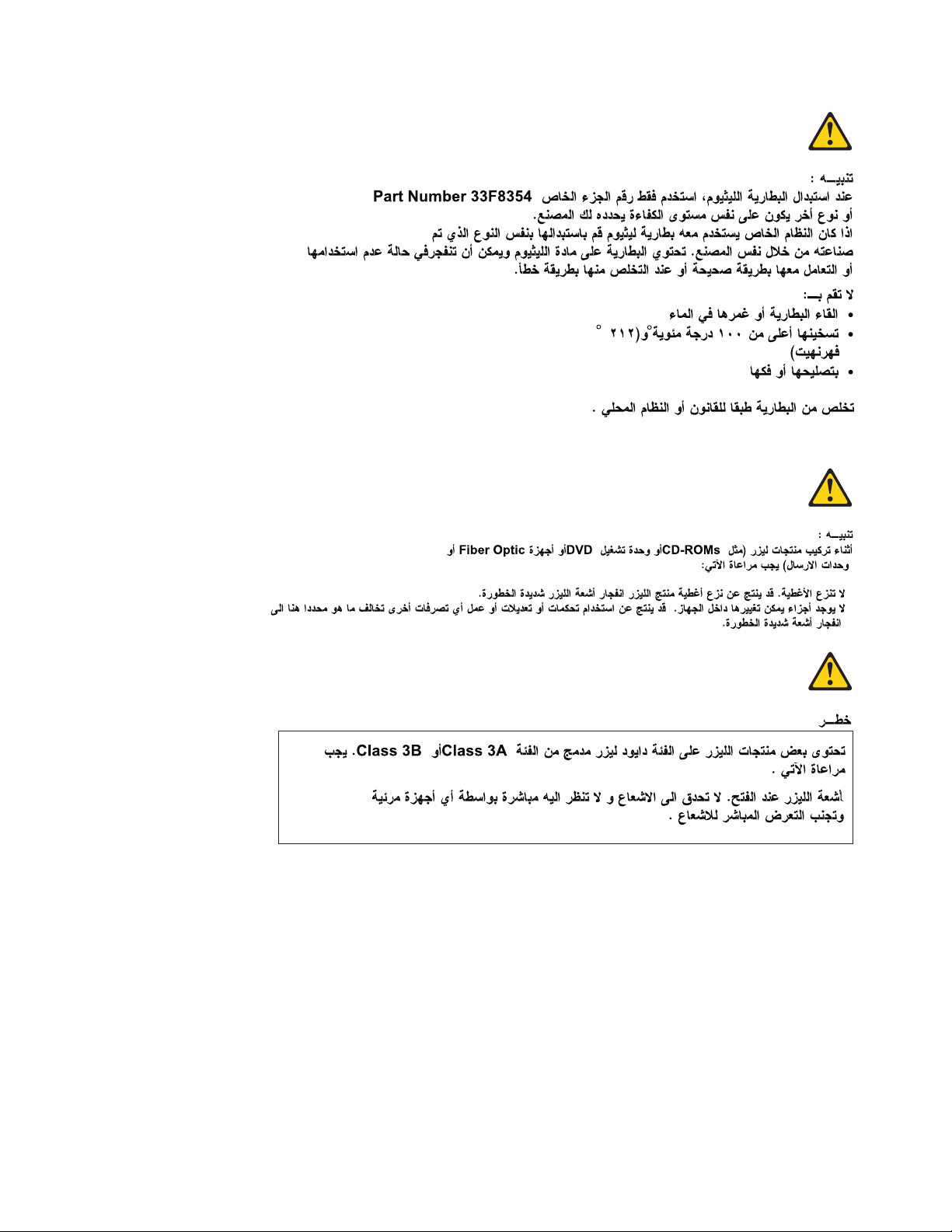
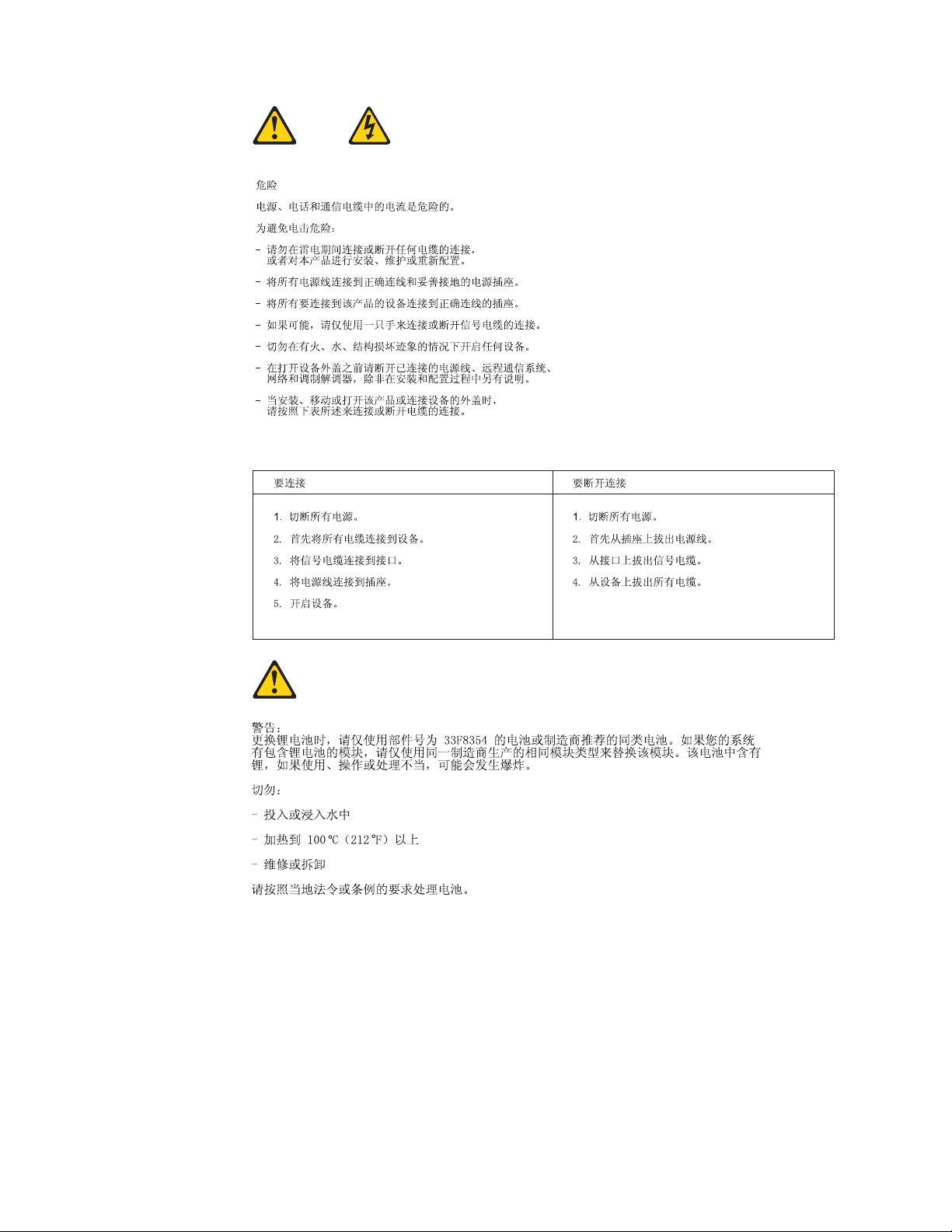
CAUTION:
When replacing the lithium battery, use only Part Number 33F8354 or an
equivalent type battery recommended by the manufacturer. If your system has a
module containing a lithium battery, replace it only with the same module type
made by the same manufacturer. The battery contains lithium and can explode if
not properly used, handled, or disposed of.
Do not:
v Throw or immerse into water
v Heat to more than 100°C (212°F)
v Repair or disassemble
Dispose of the battery as required by local ordinances or regulations.
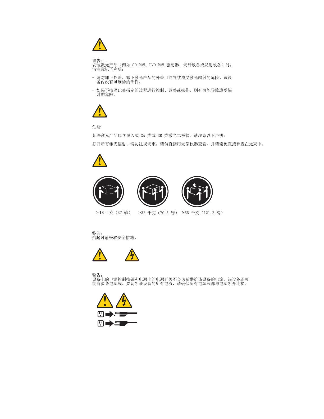
CAUTION:
When laser products (such as CD-ROMs, DVD-ROM drives, fiber optic devices,
or transmitters) are installed, note the following:
v Do not remove the covers. Removing the covers of the laser product could
result in exposure to hazardous laser radiation. There are no serviceable parts
inside the device.
v Use of controls or adjustments or performance of procedures other than those
specified herein might result in hazardous radiation exposure.
DANGER: Some laser products contain an embedded Class 3A or Class 3B laser
diode. Note the following:
Laser radiation when open. Do not stare into the beam, do not view
directly with optical instruments, and avoid direct exposure to the
beam.
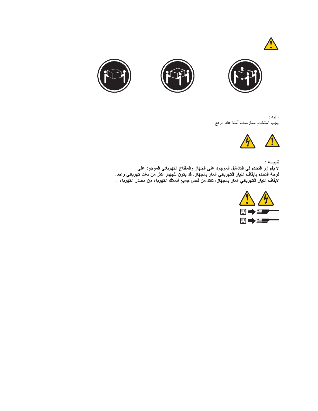
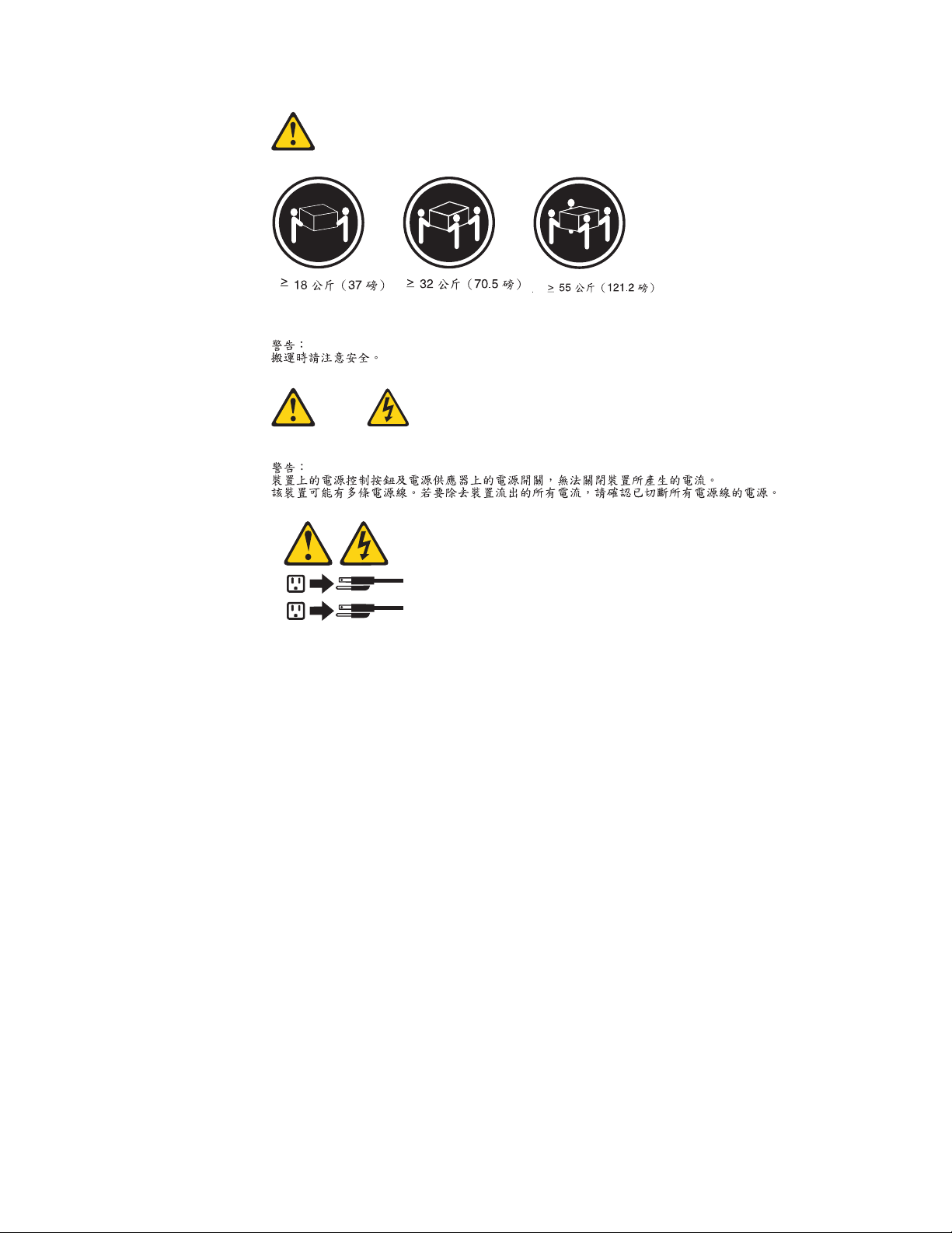
≥18 kg (37 lbs) ≥32 kg (70.5 lbs) ≥55 kg (121.2 lbs)
CAUTION:
Use safe practices when lifting.
10 Hardware Maintenance Manual
CAUTION:
The power control button on the device and the power switch on the power
supply do not turn off the electrical current supplied to the device. The device
also might have more than one power cord. To remove all electrical current from
the device, ensure that all power cords are disconnected from the power source.
1
2
Chapter 2. Safety information 11
12 Hardware Maintenance Manual
Chapter 2. Safety information 13
≥18 kg (37 lbs) ≥32 kg (70.5 lbs) ≥55 kg (121.2 lbs)
1
2
14 Hardware Maintenance Manual
PERIGO
A corrente elétrica proveniente de cabos de alimentação, de telefone e de
comunicações é perigosa.
Para evitar risco de choque elétrico:
v Não conecte nem desconecte nenhum cabo ou execute instalação, manutenção
ou reconfiguração deste produto durante uma tempestade com raios.
v Conecte todos os cabos de alimentação a tomadas elétricas corretamente
instaladas e aterradas.
v Todo equipamento que for conectado a este produto deve ser conectado a
tomadas corretamente instaladas.
v Quando possível, utilize apenas uma das mãos para conectar ou desconectar
cabos de sinal.
v Nunca ligue nenhum equipamento quando houver evidência de fogo, água ou
danos estruturais.
v Antes de abrir tampas de dispositivos, desconecte cabos de alimentação,
sistemas de telecomunicação, redes e modems conectados, a menos que
especificado de maneira diferente nos procedimentos de instalação e
configuração.
v Conecte e desconecte os cabos conforme descrito na tabela apresentada a seguir
ao instalar, mover ou abrir tampas deste produto ou de dispositivos conectados.
Para Conectar: Para Desconectar:
1. DESLIGUE Tudo.
2. Primeiramente, conecte todos os cabos
aos dispositivos.
3. Conecte os cabos de sinal aos
conectores.
4. Conecte os cabos de alimentação às
tomadas.
5. LIGUE os dispositivos.
1. DESLIGUE Tudo.
2. Primeiramente, remova os cabos de
alimentação das tomadas.
3. Remova os cabos de sinal dos conectores.
4. Remova todos os cabos dos dispositivos.
Chapter 2. Safety information 15
CUIDADO:
Ao substituir a bateria de lítio, utilize apenas uma bateria com Número de Peça
33F8354 ou um tipo de bateria equivalente recomendado pelo Se o seu sistema
possui um módulo com uma bateria de lítio, substitua-o apenas por um módulo
do mesmo tipo e do mesmo fabricante. A bateria contém lítio e pode explodir se
não for utilizada, manuseada ou descartada de maneira correta.
Não:
v Jogue ou coloque na água
v Aqueça a mais de 100°C (212°F)
v Conserte nem desmonte
Descarte a bateria conforme requerido pelas leis ou regulamentos locais.
PRECAUCIÓN:
Quando produtos a laser (como unidades de CD-ROMs, unidades de DVD-ROM,
dispositivos de fibra ótica ou transmissores) estiverem instalados, observe o
seguinte:
v Não remova as tampas. A remoção das tampas de um produto a laser pode
resultar em exposição prejudicial à radiação de laser. Não existem peças que
podem ser consertadas no interior do dispositivo.
v A utilização de controles ou ajustes ou a execução de procedimentos diferentes
dos especificados aqui pode resultar em exposição prejudicial à radiação.
PERIGO
Alguns produtos a laser contêm diodo de laser integrado da Classe 3A ou da
Classe 3B. Observe o seguinte:
Radiação a laser quando aberto. Não olhe diretamente para o feixe a olho nu ou
com instrumentos ópticos e evite exposição direta ao feixe.
≥18 kg (37 lbs) ≥32 kg (70.5 lbs) ≥55 kg (121.2 lbs)
CUIDADO:
Utilize procedimentos de segurança para levantar equipamentos.
16 Hardware Maintenance Manual
CUIDADO:
O botão de controle de alimentação do dispositivo e o botão para ligar/desligar da
fonte de alimentação não desligam a corrente elétrica fornecida ao dispositivo. O
dispositivo também pode ter mais de um cabo de alimentação. Para remover toda
a corrente elétrica do dispositivo, assegure que todos os cabos de alimentação
estejam desconectados da fonte de alimentação.
1
2
Chapter 2. Safety information 17
18 Hardware Maintenance Manual
1
2
Chapter 2. Safety information 19
20 Hardware Maintenance Manual
1
2
Chapter 2. Safety information 21
DANGER
Le courant électrique provenant de l’alimentation, du téléphone et des câbles de
transmission peut présenter un danger.
Pour éviter tout risque de choc électrique :
v Ne manipulez aucun câble et n’effectuez aucune opération d’installation,
d’entretien ou de reconfiguration de ce produit au cours d’un orage.
v Branchez tous les cordons d’alimentation sur un socle de prise de courant
correctement câblé et mis à la terre.
v Branchez sur des socles de prise de courant correctement câblés tout équipement
connecté à ce produit.
v Lorsque cela est possible, n’utilisez qu’une seule main pour connecter ou
déconnecter les câbles d’interface.
v Ne mettez jamais un équipement sous tension en cas d’incendie ou d’inondation,
ou en présence de dommages matériels.
v Avant de retirer les carters de l’unité, mettez celle-ci hors tension et déconnectez
ses cordons d’alimentation, ainsi que les câbles qui la relient aux réseaux, aux
systèmes de télécommunication et aux modems (sauf instruction contraire
mentionnée dans les procédures d’installation et de configuration).
v Lorsque vous installez, que vous déplacez, ou que vous manipulez le présent
produit ou des périphériques qui lui sont raccordés, reportez-vous aux
instructions ci-dessous pour connecter et déconnecter les différents cordons.
Connexion Déconnexion
1. Mettez les unités HORS TENSION.
2. Commencez par brancher tous les
cordons sur les unités.
3. Branchez les câbles d’interface sur des
connecteurs.
4. Branchez les cordons d’alimentation sur
des prises.
5. Mettez les unités SOUS TENSION.
1. Mettez les unités HORS TENSION.
2. Débranchez les cordons d’alimentation
des prises.
3. Débranchez les câbles d’interface des
connecteurs.
4. Débranchez tous les câbles des unités.
22 Hardware Maintenance Manual
ATTENTION:
Remplacer la pile au lithium usagée par une pile de référence identique
exclusivement, (référence 33F8354), ou suivre les instructions du fabricant qui en
définit les équivalences. Si votre système est doté d’un module contenant une
pile au lithium, vous devez le remplacer uniquement par un module identique,
produit par le même fabricant. La pile contient du lithium et peut exploser en
cas de mauvaise utilisation, de mauvaise manipulation ou de mise au rebut
inappropriée.
Ne pas :
v la jeter à l’eau,
v l’exposer à des températures supérieures à 100°C,
v chercher à la réparer ou à la démonter.
Ne pas mettre la pile à la poubelle. Pour la mise au rebut, se reporter à la
réglementation en vigueur.
ATTENTION:
Si des produits à laser (tels que des unités de CD-ROM, de DVD-ROM, des
unités à fibres optiques, ou des émetteurs) sont installés, prenez connaissance
des informations suivantes :
v Ne retirez pas le carter. En ouvrant l’unité de CD-ROM ou de DVD-ROM,
vous vous exposez au rayonnement dangereux du laser. Aucune pièce de
l’unité n’est réparable.
v Pour éviter tout risque d’exposition au rayon laser, respectez les consignes de
réglage et d’utilisation des commandes, ainsi que les procédures décrites dans
le présent manuel.
DANGER
Certains produits à laser contiennent une diode à laser intégrée de classe 3A ou
3B. Prenez connaissance des informations suivantes:
Rayonnement laser lorsque le carter est ouvert. Evitez toute expositiondirecte au
rayon laser. Evitez de regarder fixement le faisceau ou del’observer à l’aide
d’instruments optiques.
Chapter 2. Safety information 23
≥18 kg (37 lbs) ≥32 kg (70.5 lbs) ≥55 kg (121.2 lbs)
ATTENTION:
Soulevez la machine avec précaution.
ATTENTION:
L’interrupteur de contrôle d’alimentation de l’unité et l’interrupteur dubloc
d’alimentation ne coupent pas le courant électrique alimentantl’unité. En outre,
le système peut être équipé de plusieurs cordonsd’alimentation. Pour mettre
l’unité hors tension, vous devez déconnectertous les cordons de la source
d’alimentation.
1
2
24 Hardware Maintenance Manual
Loading...