

Page 1
55.5cm (22”) Full HD LED TV WITH DVB-S2,H.264,DVB-T/C AND CI
Model No.: LED-2217
For information and support, www.lenco.eu
Page 2

Contents
SAFETY INFORMATION .............................................................................................................3
Headphone Warning....................................................................................................................................................... 4
Where to install.............................................................................................................................................................. 4
LED Screen..................................................................................................................................................................... 4
Unit and Accessories ................................................................................................................5
Getting Started.........................................................................................................................5
Front view....................................................................................................................................................................... 5
Remote Control........................................................................................................................6-7
Aerial connection .....................................................................................................................8
Connecting the TV Antenna ............................................................................................................................................ 8
Connecting external devices ....................................................................................................8
HDMI Lead...................................................................................................................................................................... 8
SCART Lead.................................................................................................................................................................... 8
VGA Cable....................................................................................................................................................................... 8
CONNECTIONS ............................................................................................................................................................. 10
PC connection............................................................................................................................................................... 10
VGA, HDMI PC Connection............................................................................................................................................ 10
Satellite connection...................................................................................................................................................... 10
Connecting an audio system ........................................................................................................................................ 11
Connecting a DVD player.............................................................................................................................................. 11
COAX Connection.......................................................................................................................................................... 12
HDMI Connection.......................................................................................................................................................... 12
SCART Connection........................................................................................................................................................ 12
USB Connection............................................................................................................................................................ 12
AV Connection .............................................................................................................................................................. 13
YPbPr Connection......................................................................................................................................................... 13
Common Interface Slot...........................................................................................................14
USING YOUR COMMON INTERFACE SLOT.................................................................................................................... 14
Auto installation setup ...........................................................................................................14
Power On / Off the LED TV............................................................................................................................................ 14
INSTALLATION MENU OPERATION ..........................................................................................15
INSTALLATION GUIDE .................................................................................................................................................. 15
TV SETTINGS Menu.................................................................................................................16
Auto Scan ..................................................................................................................................................................... 16
PROGRAMME EDIT ....................................................................................................................................................... 18
Signal Information........................................................................................................................................................ 18
Cl Information .............................................................................................................................................................. 18
Dish Setup .................................................................................................................................................................... 18
MENU SETTINGS.....................................................................................................................23
Picture menu................................................................................................................................................................ 23
SOUND menu................................................................................................................................................................ 24
Time menu.................................................................................................................... ........................................... 24
OPTIONS menu............................................................................................................................................................. 24
1
Page 3

LOCK menu................................................................................................................................................................... 25
Multimedia Operation.............................................................................................................26
Basic Operation ............................................................................................................................................................ 26
1. Photo ........................................................................................................................................................................ 27
2. Music ........................................................................................................................................................................ 27
3. Movie ........................................................................................................................................................................ 28
4. Text........................................................................................................................................................................... 28
Recording Operation
DVD Operation
.........................................................................................................................
.........................................................................................................................
29-31
32-39
TROUBLE SHOOTING GUIDE .................................................................................................... 40
TECHNICAL SPECIFICATIONS .................................................................................................40
cations .......................................................................................................................................................... 40
2
Page 4
Introduction
Thank you for purchasing this LED TV which has been designed and manufactured to give you many years of trouble
free service.
You may already be familiar with using a similar product but please take time to read these instructions which have
been written to ensure you get the very best from your purchase.
HDMI
terface) is the next generation of digital interface. Unlike conventional connections, it transmits uncompressed digital and audio signals using a single cabl
input via the HDMI socket on the back of the TV.
Safety is important
To ensure your safety and the safety of others, please read the safety precautions BEFORE you operate this product.
Disclaimer
The illustrations of the LED-TV, accessories and menus shown in this User’s Manual may differ from the actual product.
SAFETY INFORMATION
IMPORTANT SAFETY INSTRUCTIONS - READ CAREFULLY BEFORE USE.
Take note of the following safety information which appears on the back of the TV.
CAUTION: TO PREVENT ELECTRICAL SHOCK, DO NOT REMOVE ANY COVER SCREWS, NO USER
SERVICEABLE PARTS INSIDE, REFER SERVICING TO QUALIFIED SERVICE PERSONNEL.
This symbol indicates that there are important operating maintenance instructions in the literature
accompanying this unit.
This symbol indicates that dangerous voltage constituting a risk of electric shock is present within this
unit.
Keep these instructions
Do not use this TV near water.
Clean only with a slightly damp cloth.
Do not block any ventilation openings.
Install in accordance with the supplied Quick Start Guide and this User Guide.
Protect the power chord from being walked on or pinched, particularly at plugs, and the point where it exits from
the TV.
Do not allow the power chord to overhang the edge of a table.
Unplug this TV during lightening storms or when unused for long periods of time.
WARNING! TO REDUCE THE RISK OF FIRE OR ELECTRICAL SHOCK, DO NOT EXPOSE THIS TV TO RAIN
OR MOISTURE. THE TV MUST NOT BE EXPOSED TO DRIPPING AND SPLASHING AND NO OBJECTS
FILLED WITH LIQUIDS SHOULD BE PLACED ON THE TV.
NOTE: No nak
NOTE: When displaying the same still picture for more than 2 hours without any interruption, the picture contours of
the continuously displayed contents may remain visible on screen, i.e. a persistant image remains. The same applies,
when displaying for more than 2 hours:
the same background/wallpaper
logos, video games, computer images, Teletext
cont ratio (e.g. 4:3 format)
These do not represent any malfunction and will not be covered by the manufacturer’s warranty
candles should be placed on the TV.
3
Page 5
This unit has been produced according to all current
safety regulations. The following safety tips should
safeguard users against careless use and the dangers
connected with such use.
Although this appliance has been carefully manufactured and rigorously checked prior leaving the factory, as with all electrical appliances it is possible for
problems to develop. If you notice smoke, an excessive
build up of heat or any other unexpected phenomena,
you should disconnect the plug from the mains power
socket immediately.
Ensur y ventilated! Never
place next to or underneath curtains!
The mains plug or appliance coupler is used as the
disconnect device, the disconnect device shall remain
readily operable.
This set should only be connected to a mains power
supply which matches that stated on the label on the
rear of the TV - do not attempt to connect it to any
other type of supply.
The socket - outlet must be installed near the equipment and easily accessible.
To prevent overload, don’t share the same mains supply socket with too many other items of equipment.
Apparatus with Class 1 construction shall be connected to a mains socket outlet with a protective earth
connection.
Keep away from rodents. Rodents enjoy biting into
el
Always hold the plug when pulling out the plug from
the mains supply sock
ex can become overloaded and cause a short circuit.
Set up the unit so that no one is able to trip over the
ex.
Do not place heavy it x, which may damage it.
Take not ex cannot be reached and pulled
by young children, avoiding injury.
Do not set up the unit near to heat sources. The casing
The screen is made of plastic and can break if damage
is done to it. Be careful when collecting sharp edged
plastic splinters to avoid injury.
Avoid placing the unit on any surfaces that may be
subject to vibrations or shocks.
To protect the unit during a thunderstorm unplug the
AC power cable and disconnect the aerial. Caution: Do
not touch the aerial (RF) connector.
When you leave your home for long periods of time,
unplug the AC power cable for safety reasons.
The unit becomes warm when in operation. Do not
place any covers or blankets on the unit in order to
prevent overheating. The ventilation holes are not to
be blocked. Do not set up near radiators. Do not place
in direct sunshine. When placing on a shelf leave 5 cm
(2”) free space around the whole unit.
exes.
ex, the
ex could be damaged by the impact of heat.
Do not allow water or moisture to enter the TV. Do
NOT use in wet or moist areas such as Bathrooms,
steamy kitchens or near swimming pools.
Do not use this unit when moisture condensation may
occur
Any repairs must be c rsonnel
only.
Do not open this unit. A non-expert attempting to repair the unit could be dangerous and potentially cause
re hazard.
Liquids spilt into the unit can cause serious damage.
Switch the set OFF and disconnect the mains power
supply, then c
attempting to use the unit again.
Do NOT remove the safety covers. There are no useable or serviceable parts inside. You may invalidate the
warranty
apparatus.
Do NOT tap or shake the screen, you may damage the
internal circuits. Take good care of the remote control,
do not drop.
Never plac rces on or
close to the TV.
High temperatures can melt plastic and lead t res.
To clean the TV use a soft dry cloth. Do NO
vents or petr
may use a damp cloth with dilute detergent.
rsonnel must only service this
For stubborn stains, you
ce person before
T use sol
-
Headphone Warning
Loud music can damage your hearing
irreversibly, therefore do not set the volume
to a high level when listening through
headphones, particularly for lengthy
listening periods.
Where to install
Locate the television away from direct sunlight and
strong lights, soft indirect lighting is recommended for
comfortable viewing. Use curtains or blinds to prevent
direct sunlight falling on the screen. Place the TV on a
sturdy platform of which the surfac
steady. This will prevent it from falling over.
Make sure the television is located in a position where it
cannot be pushed or hit by objects, as pressure will break
or damage the screen, and so that small objects cannot
be inserted into the ventilation slots or openings in the
cabinet.
LED Screen
The LED display panels are manufactured using an
extremely high level of precision technology, however
sometimes some parts of the screen may be missing
picture elements or have luminous spots. This is not a
sign of malfunction.
4
Page 6
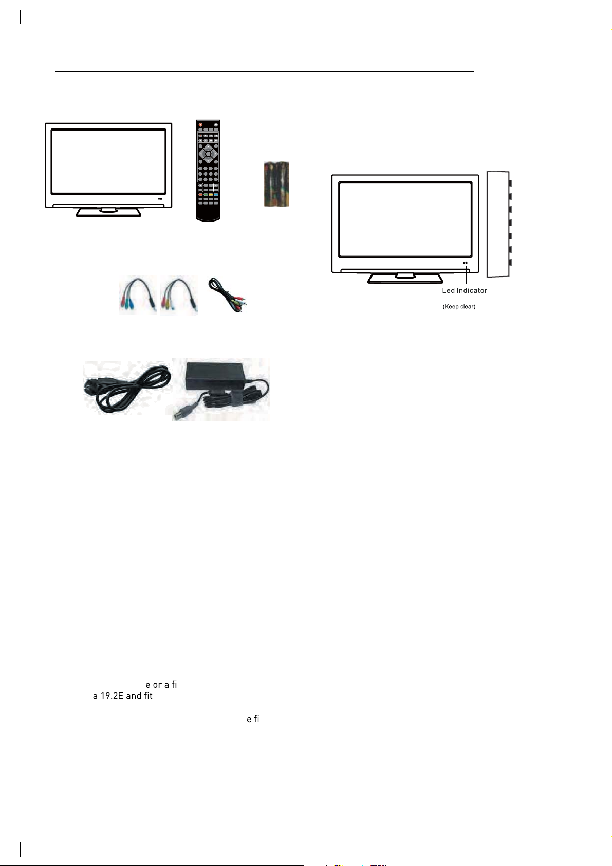
Unit and Accessories
TV set
Remote Control Batteries
POWER
REC LIST CH/LIST SUBTITLE REPEAT
REC
TV/AV
OK
MENU
1234
5678
90
PICTURE EPG
SOUND SLEEP
TV/TXT CANCEL REVEAL NICAM/A2
HOLD SIZE SUBPAGE INDEX
Getting Started
MUTE
DISPLAY
EXIT
FAV
HCLOV
SCREEN
for Remote
Control
Front view
INPUT
MENU
CH+
CH-
VOL+
VOL-
POWER
Remote Control window
Converter cable for
AV and YPbPr video
Mains cable
Mains adaptor
Mains adapter
Packaging materials are no toys. Please keep away from
children. Plastic bags can cause suffocation when pulled
over the head.
1). (IR) Infrared Receiver: Receives IR signals from the remote control.
(Power on/Standby)LED Indicator: Press POWER to turn on and off.
Indicator on(Blue) Standby mode
Indicator on(Off) Power on mode
The effective receiving range for the signal is 5-8 metres from the front of the remote
control window, and 30
window.
0
to the left or right side and 200 above or below the remote control
2).The functions of the buttons are described as bellows:
INPUT: Press to display the input source menu.
MENU: Press to display the OSD menu, press again to exit the menu.
CH+/-: Press to scan through channels.
VOL+/-: Press to adjust the volume.
POWER: Turn on/standby the TV set.
This Television is designed to work with any DTV Antenna,
Analog or Digital cabl
with Astr
xed Satellite Dish aligned
ted with a universal LNB.
Other Dishes and LNBs can be used but full set up is
required. The Television is preset for the abov
xed
dish/LNB and when quickstart is used Astra 19.2E will be
instantly tuned without need of a “search”
5
Page 7

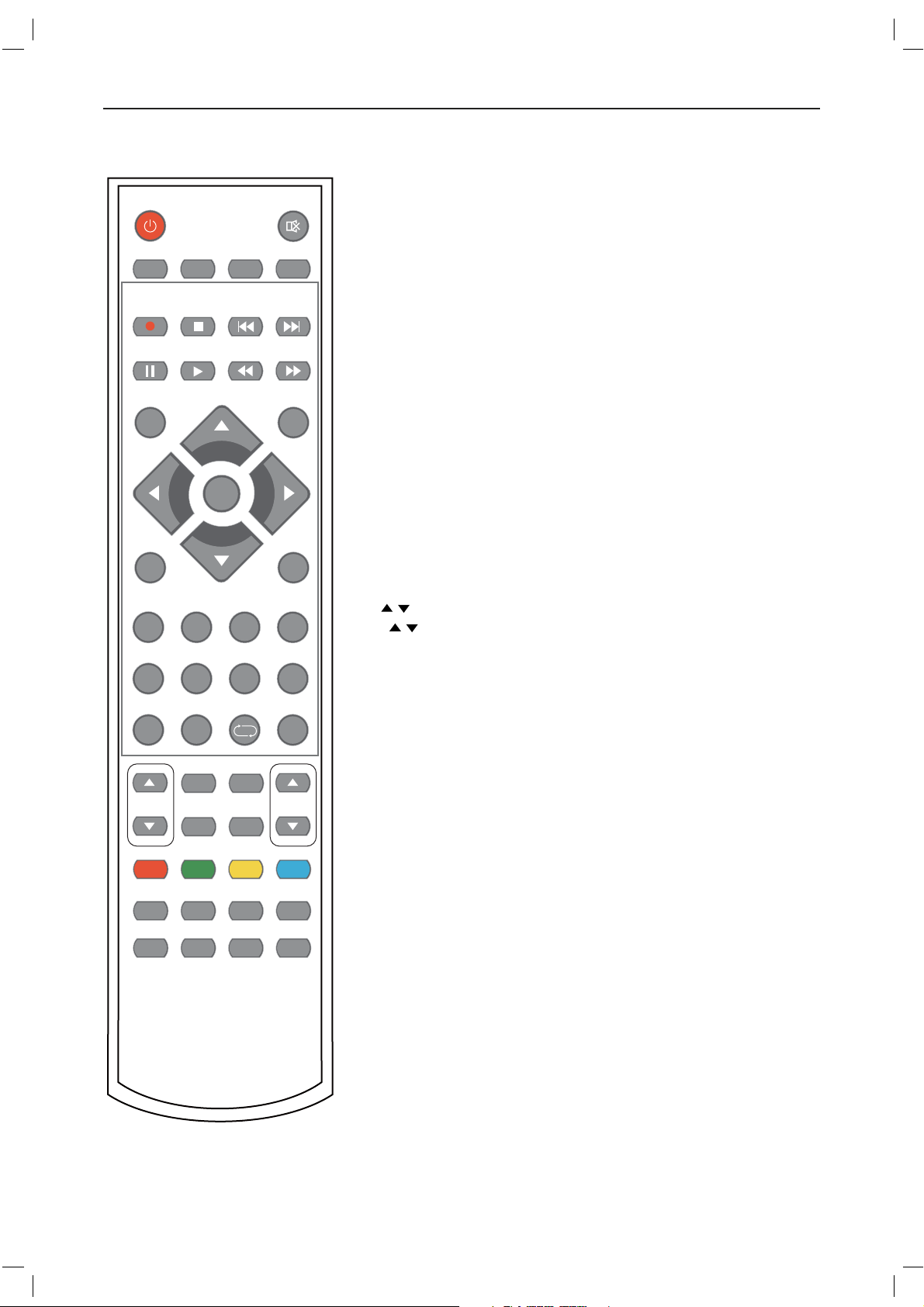
Remote control
The remote control is using Infra-Red(IR). Point it towards the front of the TV. The remote
control may not work correctly if it is operated out of range or out of angle.
ETUMREWOP
REC LIST CH/LIST SUBTITLE REPEAT
REC
INPUT
DISPLAY
OK
MENU
EXIT
1234
5678
90
FAV
POWER: Turn the TV on/standby.
MUTE: Press to mute the sound, press again or press
VOL+ to unmute.
REC LIST: Record List.
CH/LIST: Display the programs list.
SUBTITLE: Turn on/off the subtitle display in DTV mode
REP: Repeat playing the title or chapter.
REC : Press to start record the program in DTV mode.
: Stop program.
: Previous chapter.
: Next chapter.
: Pause program.
: Play program.
: Fast reverse.
: Fast forward.
INPUT: Press to display the input source menu.
DISPLAY: Press to display the current mode’s information.
MENU: System setup menu.
EXIT: Exit the OSD menu.
FAV: Display the favorite program list.
NUMBER BUTTONS
Press0-9 to select a TV channel directly when you
are watching TV.
PICTURE EPG
Return to the previous channel viewed.
SOUND SLEEP
HCLOV
CURSOR KEYS OK
Allows you to navigate the on-screen menus and adjust the
system settings to your preference.
SCREEN
TV/TXT CANCEL REVEAL NICAM/A2
HOLD SIZE SUBPAGE INDEX
6
Page 8
Remote control (continued)
ETUMREWOP
REC LIST CH/LIST SUBTITLE REPEAT
REC
INPUT
DISPLAY
OK
MENU
EXIT
1234
5678
90
PICTURE EPG
SOUND SLEEP
TV/TXT CANCEL REVEAL NICAM/A2
HOLD SIZE SUBPAGE INDEX
FAV
HCLOV
SCREEN
CH / : Scan through channels.
VOL / : Adjust the volume.
PICTURE: Select the picture mode.
EPG: To show the Electronic Program Guide during no-menu
state only in DTV mode.
SOUND: Select the sound mode.
SLEEP: Standby timer.
SCREEN: Turn on/off the screen.
TV/TXT: Turn off/on the Teletext display.
CANCEL: Cancel the Teletext display.
NICAM/A2: TV Nicam/A2 select.
REVEAL: Reveal any hidden text.
HOLD: Hold or carry on the current subpage.
SIZE: Press to see top half of page double size,
Press again to see the bottom
half of page double size. Press again for normal size.
SUBPAGE: Press to enter subpages, pressagain to cancel.
INDEX: Go to index.
Colour buttons:Short cuts-follow the coloured links in the text
7
Page 9
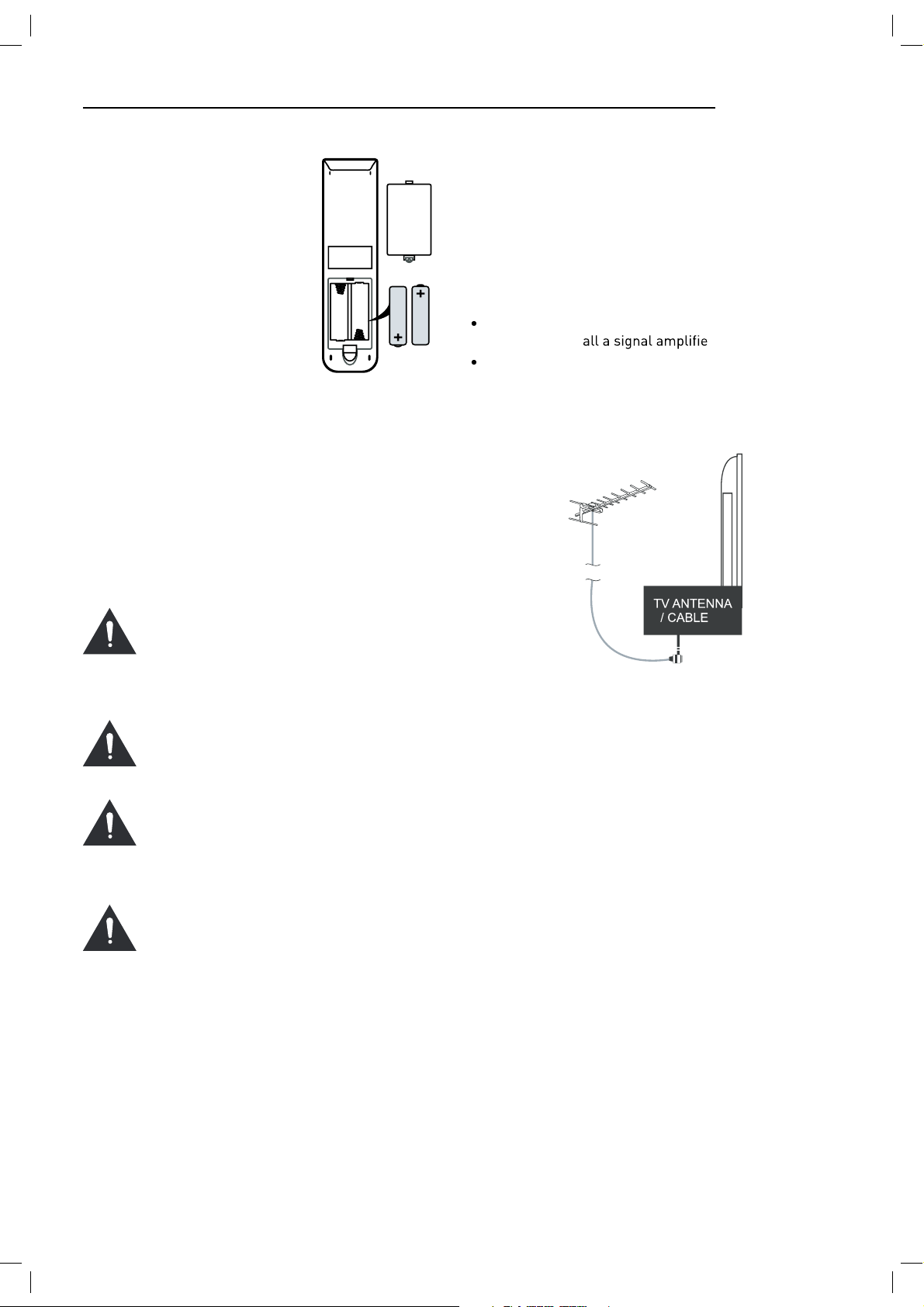
Installing Batteries in the
Remote Control
1. Remove the battery compartment cover at the rear of the
remote control by pushing
the retaining clip forward and
pulling up.
2. Install the supplied batteries, ensuring the polarity
matches what is shown in the
battery compartment.
3. Replace the battery compartment cover.
Using the Remote Control
To use the remote control point it at the TV and press the
required buttons. You must be within 6 meters and at an
angle of less than 30 degrees from the center of the TV.
NOTE: Sunshine or other strong light sources may interfere with the signal from the remote control. In this situation turn the TV away from the light source.
WARNING! DO NOT LEAVE BATTERIES IN
THE REMOTE CONTROL FOR EXTENDED
PERIODS AS THEY CAN LEAK OR CORRODE
CAUSING DAMAGE TO THE REMOTE CONTROL. CHECK THEM PERIODICALLY AND
REPLACE THEM AS REQUIRED.
WARNING! DO NOT MIX BATTERY TYPES.
WHEN INSERTING BATTERIES, REPLACE
ALL BATTERIES AT THE SAME TIME. DO
NOT MIX OLD AND NEW BATTERIES.
WARNING! EXHAUSTED BATTERIES MUST
BE TREATED WITH CARE AND DISPOSED
OF ACCORDING TO ANY SAFETY OR RECYCLING REGULATIONS IN FORCE IN YOUR
LOCAL AREA, NEVER DISPOSE OF BATTERIES INTO GENERAL WASTE, OR FIRE.
WARNING! NEVER EXPOSE BATTERIES TO
EXCESSIVE HEAT SUCH AS SUNSHINE, FIRE
OR THE LIKE.
Aerial connection
WARNING! ENSURE THE TV AND ALL ANCILLARY
EQUIPMENT IS UNPLUGGED FROM THE MAINS BEFORE
MAKING ANY CONNECTIONS!
Connecting the TV Antenna
Connect the TV antenna to the aerial socket with a 75
ohm co-axial plug. For best results use a high gain TV
aerial, preferably roof or loft mounted.
To improve picture quality in a poor signal area, purchase and inst
If the antenna needs to be split for two TVs, use a 2Way Signal Splitter (not supplied).
r.
Connecting external devices
This instruction manual shows the simplest and most effective way of connecting your TV to ancillary equipment.
Alternate methods are listed below.
HDMI Lead
You can connect this TV to a compatible device using a
HDMI lead. This method will give the best picture.
Connect the cable from the HDMI equipment to the TV
HDMI socket.
SCART Lead
You can connect this TV to a compatible device using
a SCART lead. The connection uses component video
signals, i.e. the red, green and blue (RGB) content of the
video are sent on separate signals.
VGA Cable
You can use your TV as a monitor for your personal computer by using a VGA cable. Sound from your personal
computer may also be played through the TV.
8
Page 10
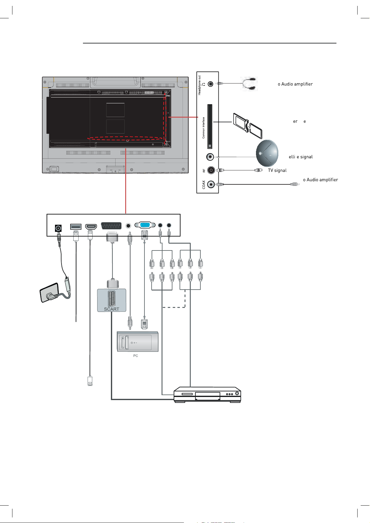
Connecting external devices (continued)
Output t
Common Int fac
POWER USB HDMI SCART PC-IN VGA YPbPr AV
MINI MINI
USB device
audio
DVB-S2
Converter cable
Sat t
Output t
Satelliten Receiver
oder Blue-Ray DVD
9
Page 11
Connecting external devices (continued)
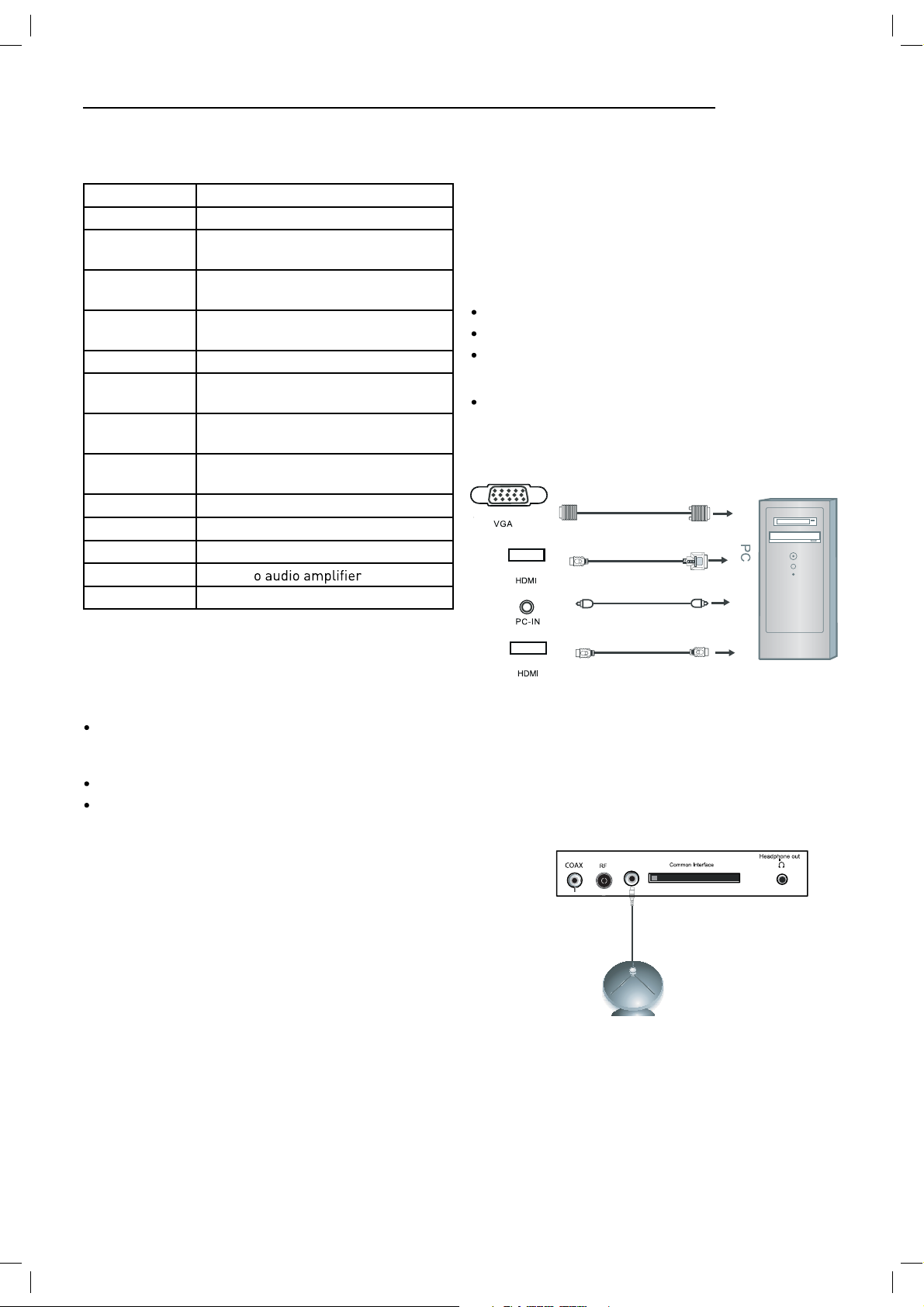
CONNECTIONS
Name Function Description
POWER Connect to power supply
HDMI
DVB-S2
VGA (PC IN)
PC-IN PC Audio input
Mini YpbPr
Mini AV
SCART
RF Connect to TV signal cable
Head phone Connect Head phone
CI CI slot (Pay as you view card slot)
Coax Output t
USB Media playback and PVR
Connect to the HDMI output of your
DVD or Satellite Box
Connect to Satellite signal
Connect to the PC VGA output to display PC graphics
Connect to the YPbPr output on external devices
Connect to AV output on external
devices
Connect to the SCART input / output
of external devices
VGA, HDMI PC Connection
Use a PC-VGA cable (not supplied) to connect the TV to
your PC. You can also use an HDMI cable to connect to
your PC (if your PC Graphic card supports HDMI). When
the HDMI cable is used, the PC audio cable is no longer
required. If you use the HDMI to DVI cable, you will need
to use the PC audio cable. Connect all cables carefully
and do not bend or break the connector pins.
When using the VGA cable
Switch on the TV
Switch on the PC
Select PC/VGA as input source
When using the HDMI cable
Select HDMI as input source
VGA cable
HDMI to DVI cable
Audio cable
Caution:
Before connecting external devices:
Makes sure to disconnect the appliances from the
power supply in order to avoid any potential damage
from occurring.
Make sure to establish the required connection.
Make sure that the connectors are properly and cor
rectly attached before connecting the appliances to the
power supply.
-
PC connection
As PCs are sometimes still supplied with a ‘conventional’
CRT monitor, you may need to adjust the display settings of your PCs graphics card, otherwise the pictures
may not appear correctly. Switch on your PC (still with
your original monitor connected) now select the screen
resolution, and select 60Hz refresh rate. Switch off your
PC, then connect it to your TV while both appliances are
still switched off.
HDMI to HDMI
(All illustrated cables are not supplied)
Satellite connection
DVB-S2
DVB-S/DVB-S2 Signal
Connect the DVB-S/DVB-S2 signal to the SATELLITE LNB
on the TV SET. Select the SATELLITE input source using
the INPUT button on the remote control.
10
Page 12

Connecting Video camera and Video recorder
Video camera
Connect the AV cable to the TV and to the video camera.
Turn on both video camera and the TV.
Select AV/CVBS source
You can now see the playback picture from the video
camera. Note:
To connect the video camera using other cables, refer
to the video camera instruction manual.
Video recorder
Connect the Scart cable to the TV and video recorder.
Turn on both video recorder and the TV.
Select Scart source
You can now see the playback picture from the video
recorder.
Note:
To connect the video recorder using other cables, refer
to the video recorder instruction manual.
Video recorder
Connecting an audio system
You can supply the TV sound to the stereo system (A) with
the Scart socket. Use a special Scart cable SCART to RCA.
(Please consult y
have a surr
Scart cable or the special Scart cable Scart to RCA.
Scart to RCA cable
structions for details). If you
coder (B) Use the
Scart cable
Scart cable
Use Scart adapter cable
Mini Audio and Video transfer
cable
(Mini AV cables is supplied)
(All illustrated cables are not supplied)
Connecting a DVD player
Connect a DVD player using either a SCART cable or the
HDMI cable. (only if your external equipment supports
HDMI).
HDMI to HDMI
Video camera
SCART
(All illustrated cables are not supplied)
When using the SCART cable
Switch on the TV
Switch on the DVD player
Select SCART as input source
When using the HDMI cable
Select HDMI as input source
11
Page 13

COAX Connection
TV Back
DVB-S2
SCART Connection
POWER USB HDMI SCART PC-IN VGA YPbPr AV
MINI MINI
Coax Cable
Connect t evice to the COAX output jack
on the TV.
HDMI Connection
TV Back
POWER USB HDMI SCART PC-IN VGA YPbPr AV
elbaCIMDH
MINI MINI
Sc
cable
D
Connect the SCART connect
and the SCART connect
ope
at connection. If the tv does not
VCR Back
D
VCR
to the ext tem
V. The SCART lead
select the SCART input automatically, select SCART using
the SOURCE button on the
emote cont v.
D
D
VCR
VCR Back
HDMI connection allo to t ansf cont ol signals th ough one cable only. These signals a e
ansf ed in digital.
t
USB Connection
ve in t lect the USB channel sou ce using the SOURCE button on the emote
cont
ol.
USB P
POWER USB HDMI SCART PC-IN VGA YPbPr AV
MINI MINI
TV Back
12
Page 14

AV Connection
TV Back
USB HDMI SCART PC-IN VGA YPbPr AV
Mini audio and video
transfer cable
Connect the VIDEO and AUDIO output jack of the DVD or VCR to the VIDEO jacks on the TV set using the RCA cable.
Match the jack colors: Video is yellow, Audio left is white, and Audio right is red. Select the AV input source via the
SOURCE button on the remote control.
YPbPr Connection
MINI MINI
Audio and video cable (RCA)
DVD or VCR back
DVD or VCR
TV Back
USB HDMI SCART PC-IN VGA YPbPr AV
MINI MINI
Audio video cable (RCA)
Audio cable
Mini video transfer cable
DVD or VCR back
DVD or VCR back
DVD or VCR
DVD or VCR
Connect the YPbPr output of the DVD or VCR to the YPbPr input on the TV set. Connect the Audio output of the DVD or
VCR to the Audio input jacks on the TV set using the RCA cable.
Match the jacks colors : Y is green, Pb is blue, Pr is red, Audio left is white, and Audio right is red. Select YPbPr input
source via the SOURCE button on the remote control.
13
Page 15

Common Interface Slot
Auto installation setup
USING YOUR COMMON INTERFACE SLOT
Common Interface
The Common Interface (CI) slot is designed to accept
the Conditional Access Module (CAM) and Smart Card
in order to view the pay TV programmes and additional
services. Contact your Pay Per View TV service provider
to get more information about the modules and subscriptions.
NOTE: Conditional Access Module and Smart Cards are
sold separately.
WARNING! SWITCH OFF YOUR TV BEFORE ANY MODULE
IS INSERTED INTO THE COMMON INTERFACE SLOT,
THEN ADD THE SMART CARD TO THE CAM.
CI Slot
CAM
Smart Card
Power On / Off the LED TV
To turn on the LED TV
Press the power button on the LED TV or the POWER button on the remote control, the standby indicator will light
green.
1. Turn on the TV and ensure ‘DTV’ Source is selected.
2. If the CAM is detected the TV will display the following
message on the screen. “Common Interface Module
inserted” wait for a few moments until the card is
activated.
3. Select the relevant digital Pay Per View channel.
4. Detailed information on the Smart Card in use is dis
played
5. Press the Ok button to access the card menu. Refer to
the Module Instruction Manual for setting details.
6. When the module is removed, the following message
will appear on the screen. “Common Interface module
removed”.
-
14
Page 16

INSTALLATION MENU OPERATION
INSTALLATION GUIDE
When powering up f rst time the Installation Guide
Will appear on screen.
ATV will install an Analogue Television cable service
DTV will install a Digital Terrestrial Television service
(DVBT)
During the channel search this menu is displayed showing the progress.
Choose the language using
OK
Choose the service to install using the
then press ok.
You will now see the quick-start menu. Ensure that your
signal cable is connected to the TV and press OK 2 times.
The TV will now install the chosen service and tune all
available channels.
You can only install one service at a time but you can return at any time to install additional services by pressing
the QUICKSTART button on the handset
buttons and then press
buttons and
15
Page 17

TV SETTINGS Menu
Input Source
DTV
CADTV
SATELLITE
ATV
SCART
YPbPr
PC
HDMI
AV
USB
All the above installations can also be accessed through
the Main Menu system. In the TV Settings menu.
To access the correct service you need the TV to be in the
correct mode, ATV, DTV, cable or Satellite.
Select the mode either from the handset or from the
source menu.
When you are in the correct mode, press Menu button on
the remote control and enter the TV Settings Menu
Press MENU button to display the main menu, use
left/right buttons to select EINSTELLUNGEN menu, press
OK or down button to enter the menu. Press MENU or up
button to return to the main menu.
NOTE: TV SETTINGS can only be selected under the ATV/
DTV/SATELLITE/CABLE modes, it is disabled whilst in all
other modes.
ATV / CABLE SETTINGS
SATELLITE / DISH SETTINGS
DIGITAL CABLE (DVBC) SETTINGS
Auto Scan
In the Auto Scan menu there are 3 options for you to select from: DVB Select type, Country and Tune Type.
DTV / DVB-T SETTINGS
16
Press
/ to select DVB Select type, Country and Tune
Type, press OK to start scanning.
If you select ATV+D
rst 50% of the processing is
for ATV tuning, while the second 50% represent DTV tuning. When ATV tuning, you can press MENU to Skip ATV
tuning and start DTV tuning or press EXIT to exit tuning.
During the channel search this menu is displayed showing the progress.
Page 18

Unlike QUICKSTART the satellite search will search the
whole satellite for channels and will not be instant.
Also the channels will appear in the order on the satellite
and not the pre-set order.
Auto search replaces any previous searched channels
with those of the new search. To add an extra satellite if
you have a suitable Dish/LNB/Switch you must use the
Dish Installation menu.
DTV Manual Tuning
You can manually tune CADTV channels in the TV SETTINGS menu.
Frequency
Select Frequency using the buttons.
Symbol (ks/s)
Select the Symbol (ks/s) using the buttons.
QAM Type
Select the QAM Type using the buttons
ATV Manual Tuning
You can manually tune ATV channels in the TV SETTINGS
menu.
Storage to
Press the buttons to change the numbered location
of the found channel.
You can manually tune DTV channels in the TV SETTINGS
menu. Press the Left/Right arrow buttons to select the
channel you wish to tune, then press OK button to scan
for the channel.
CADTV Manual Tuning
System
Select the system using the buttons.
Current CH
Displays the current channel number, press the buttons
to choose the channel you wish to modify.
Search
Press the buttons to scan through the frequencies to
ew channels.
Fine tune
In case of bad reception, you can press the buttons to
mak
ing is complete, please press the RED button to save any
found channels.
stments to the tuning. After manual tun-
17
Page 19

PROGRAMME EDIT
Use up/down keys to select program edit. Press OK or
Right button to enter the menu. Use up/down buttons to
navigate through the menu
Delete
Press the RED button to delete the highlighted channel, a
red circle will appear next to the channel name.
Press the RED button again to c
Press the MENU to return to the main menu.
Move
Press to select the channel, press yellow button to
enter the move mode, then press
nel location, press yellow button again or press OK to
c
Press MENU to return to the main menu.
lete.
to move the chan-
Dish Setup
1. If you do not hav xed dish aligned to Astra 19.2E
ted with universal LNB you will need to use this
section.
2. If you hav
or with a different LNB you will need to use this section.
3. If you have a motorised Dish with a DiSEqC rotator
and wish to tune more than one satellite you will need
this section.
4. If you are on a DiSEqC switch system you will need
this section.
rst 2 installations can be done by most people so
long as you know what satellite your dish is aligned with
Installation of 3 & 4 require an experienced user or
engineer.
To set a different Satellite or LNB
Select Satellite mode, press MENU key, navigate down to
the Dish Setup option, press OK. You will see the Satellite
Dish Setup menu.
ed Dish aligned to a different Satellite
ted with.
Skip
Press to select the channel you wish to skip.
Press the BLUE button, a logo will appear next to the
channel name and the channel will be skipped when you
scroll through the channels.
Press the BLUE button again on the highlighted channel
to disable the skip function. Press MENU to return to the
main menu.
Rename (Only available in ATV)
Modify current channel name.
Press the
the
again or press menu button to c
button to enter RENAME mode, then use
buttons to change name. Press green button
FAV
Select a program, press FAV button to set or delete the
program as the favorite
Signal Information
Only available in DTV mode, Signal Information includes:
channel /network/modulation/quality /strength.
Cl Information
When insert CI Module, display CI Information.
channel.
To set Multiple Satellites and LNBs (only possible
on multi-LNB dish, switch systems)
Use buttons to select the satellite to which your dish
is aligned. Press OK. An arrow will display against the
chosen satellite.
Press
Select the LNB type and settings for your LNB. Press the
blue Key to search the satellite channels.
Press the Exit button and the
ond satellite.
Use
your dish is aligned. Press OK. An arrow will display
against the chosen satellite.
button to navigate to LNB section of the menu.
button to select the sec-
buttons to select the second satellite to which
18
Page 20

Press button to navigate to LNB section of the menu.
Select the LNB type and settings for your second LNB
and switch settings.
Press the blue Key to search the satellite channels.
A full description of the advanced Dish set up for
multiple satellites using DiSEqC switches and DiSEqC
positioner follows. This should only be attempted by
experience users.
The Dish set up main menu page displays the main interface. The interface consists of Satellite List, Transponder
list and Dish/LNB parameter list
Satellite Edit
Press the Green button to enter the edit menu Edit parameters as described below
No. The current list number of the selected satellite Satellite name. Edited from the onscreen keyboard press
button to enter.
Input Frame (On-screen keyboard)
Longitude Direction: Added to determine the location of
the satellite. Use the
East.
Longitude Angle: Input Longitude. By moving the cursor
buttons to enter the satellite longitude.
Band: band selection. Press
arrow buttons to select West/
to select.
Delete Satellite menu
Press the YELLOW button, the c pear. Press OK to delete.
Satellite List
The Satellite list displays the satellite names.
In the input frame, use
characters.
Extend: Extended characters
Caps On: Change character case. Press OK button to
select.
Back: Delete letters, press OK to c
OK: Sure to set the naming of the satellite, and return to
Edit Menu
Cancel: Return directly back to edit menu.
and OK button to select
Add Satellite
Press the RED button to see the Add menu.
NO: This is the list placing number. This number cannot
be manually edited.
19
Page 21

Transponder List
The list shows the transponders for the selected satellite.
Edit Transponder menu
Press GREEN button to enter Transponder edit menu.
Add Transponder
Press RED button to enter the add transponder menu.
No. Can not be manually edited.
Frequency: Set the downlink frequency.
Symbol (ks/s): Set the Symbol Rate.
Polarity: (H/V)
Dish Parameter description
LNB Type: LNB Frequency
No. This is the list placing number. Nr. cannot be manu-
ally edited
Frequency: Set the downlink frequency.
Symbol (ks/s): Set the Symbol Rate.
Polarity: (H/V )
Delete Transponder
Press the YELLOW button, the c pear. Press OK to delete.
20
Page 22

Highlight the LNB Type , and use the buttons and Ok
to enter submenu then you c
rameters.
LNB Power: Polarization switching power supply, Press
to select On/Off.
KHz: The level of the LO switch / DS switch ( Require
the user to have installed 22KHzSatellite signal switch).
Press
to select Auto/On/Off.
Auto: Automatically issued 22 KHz pulse signal to control
switching.
On/Off: Manual control switch.
Tone burst: Double Single Switch (Require users to install
Tone burst switch), Press
to select Burst A/Burst
B/None.
Burst A /Burst B: Manually switch the satellite A/B.
DiSEqC1.0.4: select 1 switch ( Require the user device
support DiSEqC 1.0 protocol). Press
to select LNB1/
LNB2/ LNB3/LNB4/None.
LNB1/LNB2/LNB3/LNB4: Corresponding to a satellite ,
After selecting the corresponding list will appear in the
satellite list.
DiSEqC 1.1: 16 select 1 switch ( Require the user device
support DiSEqC1 .0 protocol) Equipment needs support
DiSEqC 1.1 protocol, Most control 16
LNB. Press to
select LNB1~LBN16/None.
LNB 1-LNB 16: Corresponding to a satellite, After selecting the corresponding list will appear in the satellite list.
Motor: Control of multi-satellite polar (Require the user
device support DiSEqC1.2 or DiSEqC1.3 protocol), Left
and right buttons to select DisEqC1.2/ DisEqC1.3/None.
DisEqC1.2: DisEqC1.2 Protocol selection
DisEqC1.3: DisEqC1.3 Protocol selection
For Mot
te “DisEqC1.2” , Operating Instructions:
Press RED button to enter “Set Limit" menu.
Press OK button to enter Set Position menu.
On: Allowed to receive Horizontal / Vertical Polarization
program.
Off: out-off of supply.
21
Page 23

Move Continue: Control of the east or the west continued
to turn the polar axis to the desired position.
Move Step: Control of the east or wes
xed polar
axis step rotation.
Set West Limit: The current position is set to the maximum point of the west.
Set East Limit: The current position is set to the maximum point of the east.
Goto Reference: Back to the default values.
Disable Limit: Abolish the current limit set.
Press RED button to enter “Set Limit” and Mot
as “DiSEqC1.3” “Set Limit’ menu same.
Press GREEN button to enter Set Location menu.
Move Auto: East or west of Automatic Control continued
to turn the polar axis to the desired position.
Move Continue: Manual control of the east or the west
continued to turn the polar axis to the desired position.
Move Step: Control of the east or wes
xed polar
axis step rotation.
Store Position: Save the current rotation angle of polar
axis.
Goto Position: Control the polar angle automatically to
the previously saved.
Goto Reference: Control the angle of polar axis automatically to the default. When Mot
te “DisEqC1.3”.
Location: Select the user area or similar areas, if the user
is not in the system default settings when in these areas,
can select Manual custom settings.
Longitude Direction: Select the user area in the east
longitude or longitude.
Longitude Angle: Longitude angle. Select the user area in
which the longitude, Enter the appropriate values to move
the cursor.
Latitude Direction: Select the user area in the latitude or
latitude.
Latitude Angle: Select the user latitude area, Enter the
appropriate values to move the cursor.
Press OK button to enter Set Position menu.
22
Page 24

Move Auto: East or west of Automatic Control continued
to turn the polar axis to the desired position.
Move Continue: Manual control of the east or the west
continued to turn the polar axis to the desired position.
Move Step: Control of the east or wes
axis step rotation.
Store Position: Save the current rotation angle of polar
axis.
Goto Position: Control the polar angle automatically to
the previously saved.
Goto Reference: Control the angle of polar axis automatically to the default.
GotoX: Area based on user input parameters, Automatically calculate the satellite over the area,
Control the polar axis rotation to the right place.
xed polar
Scan Menu
When all the parameters after. Press BLUE button to Tuning the setup menu to enter.
Scan Mode: Scan from Default, Blind Scan and Network
to select.
Default: Default search program.
Blind Scan: Searches all the programs for the LNB
settings. (This is a long sear
including new Channels).
Network: Search the known channel frequencies for the
selected LNB & Satellite settings at the time of manufacture. (This will be the quickest search)
Channel Type: FTA (Free to Air) or ALL (Free to Air and
Pay Channels)
Service Type: DTV (DVB TV) or Radio (DVB Radio) or both
DTV & Radio
Polarization: Polarization of the LNB (Low noise Block),
(H) Horizontal or (V) Vertical Or Auto (according to the settings in the LNB set-up pane.)Menu Settings
MENU SETTINGS
Picture menu
Picture Mode: Choose from Standard, Dynamic, User and
Mild.
Note: Contrast, Brightness, Colour and sharpness are
only available and can be adjusted in the User mode
option in the Picture Mode Settings.
Contrast: Controls the difference between the brightest
and darkest regions of the picture.
Brightness: Controls the overall brightness of the picture.
Colour: Control the colour.
Sharpness: Increase this setting to see crisp edges in the
picture; decrease it for soft edges.
Tint: Controls the tint ( NTSC mode only).
Colour Temperature: Choose from Medium, Cool, User
and Warm.
Red: Controls the red colour of the picture.
Green: Controls the green colour of the picture.
Blue: Controls the blue colour of the picture.
Aspect Ratio: Choose from , 4:3, 16:9, Zoom1,
Zoom2, and Panorama.
Noise Reduction: Choose interference noise modes from
Off, Low, Middle, High and Default.
23
Page 25

SOUND menu
Sound Mode: Allows you to select among: Standard, Mu-
sic, Movie, Sports and User.
Treble (Can be adjusted when the sound mode is set to
User): Controls the relative intensity of higher pitched
sounds.
Bass (Can be adjusted when the sound mode is set to
User): Controls the relative intensity of lower pitched
sounds.
Balance: To adjust the balance of the left and right speakers audio output, or turn off the volume of the left or right
speaker.
Auto Volume: This feature automatically adjusts the audio
level when the TV is turned on. This function is activated
by selecting “On”.
Surround Sound: Turn on / off the surround sound function by selecting “off” or “on”
SPDIF MODE:
Auto.
Allows you to select among: Off, PCM and
TIME menu
On Time:
the time when the TV set will be turned on automatically, you could
also set the frequency, volume and program.
Sleep Timer:
20min, 30min, 60min, 90min,
Auto Sleep: Turn on/off the auto standby function.
Time Zone: Allows you to select the time zone.
Press OK
button to enter the submenu, you could set
Allows you to setup the sleep timer among: 10min,
120min,180min, 240min and off.
OPTIONS menu
OSD Language: Allows you to select the on screen display
menu language.
Audio Language (can only be selected in DTV mode): Select the audio language.
Subtitle Language (can only be selected in DTV mode):
Select the subtitle language.
Menu Time Out: Allows you to setup the length of time
that the on screen display is visible: 5s, 10s, 15s, 20s, 25s,
30s, 35s, 40s.
Country: This is defaulted to Germany, but can be
changed by using the Auto tune function.
Restore Setting: Press the OK button to restore the factory default settings.
Clock: Use the and buttons to select the position,
and use the and buttons to set the
Note: User can not change time manually during DTV
mode, for time is from signal source directly.
Off Time:
could set the time when the TV set will be turned off
automatically, you could also set the frequency.
24
Press
button to enter the submenu, you
OK
time.
Page 26

LOCK menu
The password must be entered to access the Lock Menu.
The default password is 0000. Once inside the menu you
can change the password to your own choice.
Channel lock is used to block selected Channels
Parental Guidance blocks programmes according to their
parental level.
25
Page 27

7.Hotel Mode
26
Input Source
DTV
CADTV
SATELLITE
ATV
SCART
YPbPr
PC
HDMI
AV
USB
Page 28

Multimedia Operation
Basic Operation
1). Press the INPUT button on the remote control to display the input source menu, select USB
source by the / buttons, and press OK button to enter the Multimedia menu seen below.
Input Source
DTV
CADTV
SATELLITE
ATV
SCART
YPbPr
PC
HDMI
AV
USB
Select
2). Insert USB device, you will find the name of the device display on the screen.
MAINS MENU
PHOTO MUSIC MOVIE TEXT
Disk C:
USB device list
MAINS MENU
PHOTO MUSIC MOVIE TEXT
Select
Hints for operation
Hints and informations of USB device
3). Press / button to select the kind of the files in the device you want to program from PHOTO,
MUSIC, MOVIE and TEXT. Press / button to select the device and press OK button to enter.
Return to
Preview
device list
Up Folder
Informations
Press / / / buttons to move , and press OK button to select the file or unfold the folder,
Then press button to program the files (be signed) you select or the files in the fold you select,
You can display the option table on the bottom of the screen by OK button, press button to hide.
Press button to stop and exit the full screen program.
27
Page 29

Multimedia Operation
1. Photo
Play the photo
Press / button to select the option on the table, and press OK button to change.
Repeat: Select the repeat mode from Repeat All, Repeat 1, Repeat None.
Music: Play/pause the music program (you can only play or pause the music you have programed).
Playlist: Display the playlist on the screen, and you can select the photo by / button, and
press OK button to program. Press / button to return to the options table.
Info: Display the information of the photo.
Rotate: Rotate the photo clockwise/counterclockwise.
Zoom Out/In: Zoom out/in the photo.
Move View: Move the photo in Zoom out mode.
2. Music
Play the music
Press / button to select the option on the table, and press OK button to change.
Press / button to select the music, and press OK button to program.
Repeat: Select the repeat mode from Repeat All, Repeat 1, Repeat None.
Goto Time: Program the music form the time you set.
Press OK button to display the time table, and select the position by / / / button,
set the time by the number buttons, select “OK” and press OK button to search.
Screen Saver: Press BLUE button to enter the Screen Saver mode, press again to exit.
28
Page 30

Multimedia Operation
3. Movie
Play the movie
GOTO Time
Press / button to select the option on the table, and press OK button to change.
Repeat: Select the repeat mode from Repeat All, Repeat 1, Repeat None.
Set A-B: Select and play the preferable paragraph of the program by seting A and B at the
beginning and end, and there will be a sign on the left screen, press OK button again to cancel.
Playlist: Display the playlist on the screen.
Info: Display the information of the movie.
Slow: Play the programs at slow speed, press button to cancel.
Step: Step the programs by OK button, press button to cancel.
Goto Time: Program the movie form the time you set.
Zoom out/in: Zoom out/in the movie screen.
Aspect Ratio: Select the aspect ratio of the screen display.
Move View: Move the photo in Zoom out mode.
4. Text
Play the text
Press / button to select the option on the table, and press OK button to change.
Prev/Next page: Turn to previous/next page of the text.
Prev./Next: Turn to previous/next file.
Stop: Stop auto turning pages.
Music: Play/pause the music program.
Playlist: Display the playlist on the screen.
Info: Display the information of the text.
29
Page 31

Recording Operation
PVR settings
Press the MENU button, and select CHANNEL menu.
Recording Timer
1). Recorded List
2). Recording Timer
Display the recorded list
Recorded list: Display the Recorder List menu,
and changed the mode of program.
INFO: Display the information of the program you recorded.
RED button: Delete the program you select.
Set the recording timer
The TV will record the program automatically according
to your settings.
TITLE: Display the name of the recording program.
MODE: Select the record mode.
Start Time: Select the start recording time.
End Time: Select the end recording time.
Press OK button to save the setting and exit the menu.
30
Page 32

Recording Operation
3). Schedule List
Display the recorder shedule
Note: a. Could’t add shedules which have existent on the list;
b. Could’t add shedules when the list is full, you have to delete some schedules;
c. You could delete a schedules by RED button on the remote control.
4). PVR File System
Setup the PVR File system before you start recording.
Select Disk: Select the device for the Record files.
Check PVR File System
USB Disk: Display the USB state.
Format: Format the USB device for PVR operating.
Time Shift Size: Display the size of the USB device (The device has been formated).
Speed: Display the speed of the USB device (The device has been formated).
31
Page 33

Recording Operation
5) Record Start
When you finish the settings above, you could start recording by select Start Recording in the
menu and press OK button in DTV and DVBS mode. (You can also start recording by press the button
on the remote control)
Record buttons
Recording: Press to enter the recording mode.
PAUSE: Press to enter the timeshift mode.
Recording list: Press to display the recording list.
Stop: Press to stop recording.
Recording menu
When you press REC button, the screen will display the recording menu as below:
Full mode
Simple mode
Note: a. You could change the mode of Recording menu by REC/Exit button.
b. Press STOP button to exit the recording mode.
c. Press PLAY button to play the program you are recording from the beginning.
d. Press Recording list button to display the Recorder list, and you could play the
program you selected. The recording will be going on, and the Recording menu
will display when you exit the Recorder list.
Timeshift
Press PAUSE button to enter the Timeshift mode, and the picture will be paused, the
recording will begin.
Note: a. You could change the mode of Timeshift menu by REC/Exit button.
b. Press STOP button to exit the Timeshift mode.
c. Press PLAY button to play the program you are recording from the beginning.
Playback
The current state of the program
The current time
The process of the program
A-B mark
32
The name and number
of the program
Page 34

TROUBLE SHOOTING GUIDE
To assist in locating possible faults use the help guide below.
NOITULOSMOTPMYS
No Picture, no sound Check that the TV is correctly plugged in. Check that the TV is connected to a suit-
able power source. Check the electrical supply is turned on.
raselbacehttahtkcehC.noderewopsiVTehttahterusnEerutciPoN
ted securely. Ensure
the aerial and/or external sources are connected. Press the SOURCE button to
change the source. Turn the TV on or off.
lennahcrehtonaothctiwS.tessiedometuMfikcehcdnanottubETUMehtsserPdnuoSoN
and see if the same problem occurs. Press V+ button to see if the problem can be
solved.
No picture on some channels Check that correct channel is selected. Adjust the antenna.
No colour on some channels
(black &white)
Noisy, Snowy, Ghosting picture. Check the antenna is connected correctly. Check that the antenna Is in good condi-
If none of the suggestions seem to work, try switching your TV off and then on again. If this does not work contact our
technical helpline.
NOTE: The TV must only be repair
as the TV has dangerous voltages inside that may cause fat
Check if the same problem exists on other channels. Ensure the correct picture
settings are selected.
tion. Try moving the antenna.
registered service person. Never attempt to remove the back cover
re.
TECHNICAL SPECIFICATIONS
cations of the TV that you have just purchased may vary from the information in this table due to technical in-
novations.
cations
TV System SECAM/BG/DK/L/L’
Audio System BG/DK/I/L/L’
Screen size 21.6(Diagonal)
Resolution 1920 x 1080 Pixel(RGB)
Aerial input 75 Ohm (unbalanced)
Audio output power 2 x 3W
Power requirements 12V 3.33A
Power consumption 40W
Standby power consumption <0.5W
2/4.9Kg.4thgieW
Remote contr cations
Type Infrared
Control distance 5m
Control angle 30 degrees (Horizontal)
Batteries 2 x 1.5V, Size AAA
Dimensions 48 x 193 x20mm
Weight 120g (without batteries)
33
Page 35

I LENCO II LED-2217
27
39
55,5
22
 Loading...