

Page 1

Version 2.4
English
Leica TPS700 Series
User Manual
Page 2
Electronical Total Station
Symbols Used in this Manual
Congratulations on your purchase of a new Leica
Geosystems Total Station.
This manual contains important safety directions
as well as instructions for setting up the product
and operating it. Refer to "Safety Directions" for
further information.
Read carefully through the User Manual before
you switch on the product.
Product Identification
The model and the serial number of your product are
indicated on the type plate.
Enter the model and serial number in your manual and
always refer to this information when you need to contact
your agency or Leica Geosystems authorized service
workshop.
Type: _________________
Serial no.: _________________
Trademarks
• Windows is a registered trademark of Microsoft
Corporation
All other trademarks are the property of their respective
owners.
The symbols used in this User Manual have the following
meanings:
DANGER
Indicates an imminently hazardous situation
which, if not avoided, will result in death or
serious injury.
WARNING
Indicates a potentially hazardous situation or an
unintended use which, if not avoided, could result
in death or serious injury.
CAUTION
Indicates a potentially hazardous situation or an
unintended use which, if not avoided, may result
in minor or moderate injury and / or appreciable
material, financial and environmental damage.
Important paragraphs which must be adhered to
in practice as they enable the product to be used
in a technically correct and efficient manner.
Product Identification
2
TPS700 User Manual 2.4.0en
Page 3

Contents - Overview
Contents.....................................................................................
Introduction ...............................................................................
Measuring Preparation / Setting up .........................................
Operating the Instrument / Measuring.....................................
Checking and Adjusting ...........................................................
Care and Storage.......................................................................
Safety Directions .......................................................................
Technical Data ...........................................................................
Corrections and Formula..........................................................
Index ...........................................................................................
4
6
15
24
36
40
44
64
74
78
TPS700 User Manual 2.4.0en
3
Contents - Overview
Page 4

Contents
Introduction 6
Important Components 7
Distance measurement 8
Automatic Target Recognition ATR 10
Technical Terms and Abbreviations 1 1
Area of Applicability 13
PC Program Package Leica Geo Office Tools (LGOTools) 14
Installation on the PC 14
Program content 14
Tools 14
Measuring Preparation / Setting up 15
Setting up 15
Power Supply 16
Inserting / Replacing Battery 17
Charging / Discharging Battery 18
Powering the Total Station from an External
Power Supply 19
Setting Up the Tripod 20
Centering with Laser Plummet / Coarse Level-Up 21
Accurate Levelling-Up with Electronic Level 22
Laser Intensity 22
Centering with Shifting Tribrach 23
Hints for Positioning 23
Operating the Instrument / Measuring 24
Keypad 24
Trigger Key 27
Buttons 27
Symbols 28
User Entries 29
Entry of numeric values 29
Entry of Alphanumeric Values 30
Inserting Characters/Numbers 30
Deleting Letters/Numbers 31
Character Set 32
Measuring 33
Station Block 34
Checking and Adjusting 36
Tripod 36
Circular Level 36
Circular Level on the Tribrach 36
Laser Plummet 37
Reflectorless EDM 38
Contents
4
TPS700 User Manual 2.4.0en
Page 5

Contents
Care and Storage 40
Transport 40
In the Field 40
Inside Vehicle 41
Shipping 41
Storage 42
Cleaning 43
Safety Directions 44
Intended Use 44
Permitted use 44
Prohibited use 44
Limits of Use 45
Responsibilities 46
International Warranty, Software Licence Agreement 47
Hazards of Use 48
Laser Classification 52
Integrated Distancer, Invisible Laser 52
Electronic Guide Light EGL 58
Laser Plummet 59
Electromagnetic Compatibility EMC 61
FCC Statement, Applicable in U.S. 63
Technical Data 64
Distance measurement (infrared) 67
Distance measurement (reflectorless) R100 / R300 69
Distance measurement (long range) 71
Automatic Target Recognition A TR 72
Application Programs 73
Corrections and Formula 74
Atmospheric Correction ∆D1 74
Reduction Formulae 77
Index 78
TPS700 User Manual 2.4.0en
5
Contents
Page 6
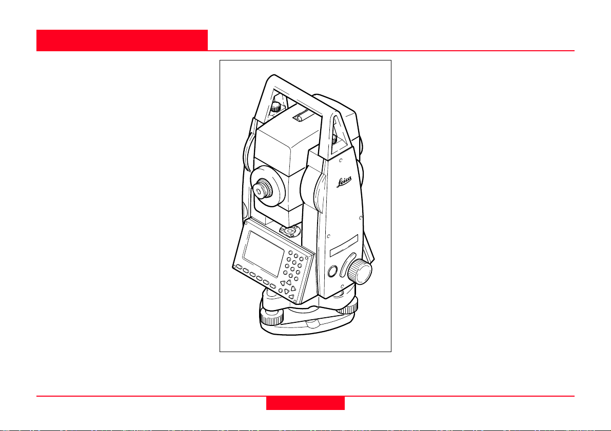
Introduction
Special Features
The Leica Geosystems TPS700
performance series is a proven
generation of electronic total station
designed for the construction site.
A solid design and highly
sophisticated functions enable the
user to use the instruments efficiently
and accurately. Innovative features
such as the laser plummet or the
endless drives contribute
significantly in making daily
surveying jobs easier.
The instruments are best suited for
cadastral and construction surveys,
for surveying buildings and for civil
engineering with emphasis on
stakeouts and tacheometric surveys.
The operation of the instrument's
functions can be learned easily in a
short space of time.
• Reflectorless measuring EDM
R100 or R300
• Automatic target recognition ATR
• Large display, alphanumeric
keypad
• Endlessdrive
• Laser plummet
• Two axis compensator
• Camcorder batteries
• Light, slender construction
• On-board software and data
memory
TC700z01
Introduction
6
TPS700 User Manual 2.4.0en
Page 7
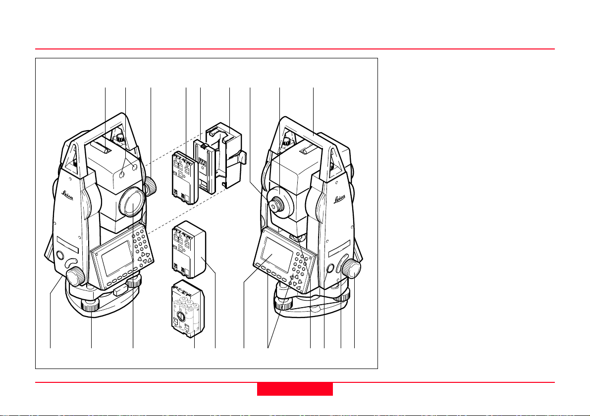
Important Components
2
1 3 8 9
10 201413 15
11 1817
12
5
4
1 Optical sight
6
7
16
19
2 Guide light EGL (optional)
3 Vertical drive
4 Battery GEB111 (optional)
5 Battery spacer for GEB111
6 Battery holder for GEB111/
GEB121/ GAD39
7 Eyepiece
8 Telescope focusing ring
9 Detachable carrying handle
10 Serial interface RS232
11 Foot screws tribrach
12 Telescope with integrated EDM,
ATR (optional) and EGL
(optional)
13 Battery adapter GAD39 for 6
single cells (optional)
14 Battery GEB121 (optional)
15 Display
16 Keypad
17 Circular level
18 On/Off key
19 Trigger key
20 Horizontal drive
TC700Z02
TPS700 User Manual 2.4.0en
7
Introduction
Page 8
Distance measurement
A laser distancer (EDM) is
incorporated into the instruments of
the TPS700 series.
In all versions, the distance can be
determined by using an invisible
infrared beam which emerges
coaxially from the telescope
objective.
Measurements to strongly
reflecting targets such as
to traffic lights in infrared mode
without prism should be avoided.
The measured distances may be
wrong or inaccurate.
For applications without reflector, the
TCRApower and TCRAultra version
also use a visible red laser beam
which emerges in the same manner.
A special arrangement of the EDM,
and appropriate arrangement of the
beam paths, enable ranges of over
five kilometres to be attained with
standard prisms.
Reflector tapes can also be used,
and measurement is also possible
without a reflector.
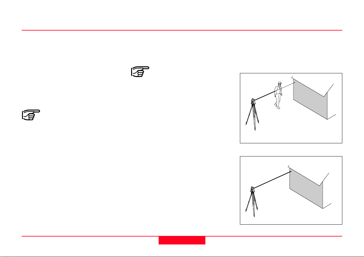
When a distance
measurement is triggered,
the EDM measures to the object
which is in the beam path at that
moment.
If e.g. people, cars, animals, swaying
branches, etc. cross the laser beam
while a measurement is being taken,
a fraction of the laser beam is
reflected and may lead to incorrect
distance values.
Avoid interrupting the measuring
beam while taking reflectorless
measurements or measurements
using reflective foils. Measurements
to prism reflectors are only critical if
an object crosses the measuring
beam at a distance of 0 to 30m and
the distance to be measured is more
than 300m.
In practice, because the measuring
time is very short, the user can
always find a way of avoiding these
critical situations.
Incorrect result
Correct result
1100z461100z47
Introduction
8
TPS700 User Manual 2.4.0en
Page 9
Distance measurement
Reflectorless
Be sure that the laser beam
is not reflected by anything
close to the line of sight (e.g. highly
reflective objects).
When a distance
measurement is triggered,
the EDM measures to the object
which is in the beam path at that
moment. In case of temporary
obstruction (e.g. a passing vehicle,
heavy rain, fog or snow) the EDM
may measure to the obstruction.
When measuring longer dis-
tances, any divergence of
the red laser beam from the line of
sight might lead to less accurate
measurements. This is because the
laser beam might not be reflected
from the point at which the
crosshairs are pointing.
Therefore, it is recommended to verify that the R-laser is well collimated
with the telescope line of sight (refer
to the chapter "Checking and
adjusting").
Do not measure with two
instruments to the same
target simultaneously.
Red laser to prisms
Accurate measurements to
prisms should be made with
the standard program (Infrared
mode).
Red laser to reflector tape
The visible red laser beam can be
used to measure to reflective foils,
also. To guarantee the accuracy the
red laser beam must be
perpendicular to the reflector tape
and it must be well adjusted (refer to
the chapter "Checking and
adjusting").
Make sure the additive
constant belongs to the
selected target (reflector).
TPS700 User Manual 2.4.0en
9
Introduction
Page 10
Automatic Target Recognition ATR
TCRApower and TCRAultra
instruments are motorized and
equipped with Automatic Target
Recognition (ATR) coaxially in the
telescope. The Electronic Guide
Light (EGL), mounted on the
telescope, is optional.
ATR mode
These instruments permit automatic
measurements to normal prisms and
reduce the tedious task of precise
visual sighting to prisms.
The prism is sighted with the optical
sight only. Initiating a distance
measurement will turn the instrument
with the help of the motors to sight
the prism-centre automatically.
The angles V and Hz are measured
to the centre of the prism after
completion of the distance
measurement.
As with all other instrument
errors, the collimation error
of the automatic target recognition
(ATR) must be redetermined
periodically (Refer to chapter
"Determing Instrument Errors" in the
Field Manual).
To speed up measuring
time, in ATR mode the
crosshairs are not positioned exactly
over the center of the prism. The
remaining distance between the
crosshairs and the center of the
prism is measured electronically and
the horizontal and vertical angles are
corrected accordingly. As a result, in
ATR mode the displayed angles are
of the usual precision and
correspond to the specifications of
your instrument.
Introduction
10
TPS700 User Manual 2.4.0en
Page 11
Technical Terms and Abbreviations
KA
SA
SA
ZA
KA
KA
HK
VK
SA
ZA = Line of sight / collimation
V
ZA
Hz
axis
Telescope axis = line from the reticle
to the centre of the objective.
SA = Standing axis
Vertical rotation axis of the total
station.
KA = Tilting axis
Horizontal rotation axis of the
telescope (Trunion axis).
V = Vertical angle / zenith angle
VK = Vertical circle
With graduated scale for reading the
V-angle.
Hz = Horizontal angle
HK = Horizontal circle
With graduated scale for reading the
Hz-angle.
TC700Z24
TPS700 User Manual 2.4.0en
11
Introduction
Page 12
Technical Terms and Abbreviations
Standing axis
inclination
Angle between
plumb line and
standing axis.
TC700z37
Line-of-sight
error (Hzcollimation)
The line-of-sight
error is the
deviation from
the
perpendicular
between the
tilting axis and
the line-of-sight.
This can be
eliminated by
measuring in
both faces.
C
TC700z16
V-index
(Vertical index
i
TC700z13
Plumb line /
Compensator
TC700z38
Zenith
TC700z39
Reticle
TC700z40
error)
With horizontal
line-of-sight the
V-circle reading
should be
exactly
90°(100gon).
Direction of
gravity. The
compensator
defines the
plumb line within
the instrument.
Point on the
plumb line above
the observer.
Glass plate
within the
telescope
engraved with
the cross hair
lines.
The deviation
from this value is
termed V-index
(i).
Introduction
12
TPS700 User Manual 2.4.0en
Page 13

TechnicalTerms and Abbreviations
Area of Applicability
E0, N0, H
hi
0
E, N, H
SD
HD
hr
dH
SD Indicated meteorological
corrected slope distance
between instrument tilting axis
and centre of prism/laser spot
(TCR)
HD Indicated meteorological
corrected horizontal distance
dH Height difference between
station and target point
hr Reflector height above ground
hi Instrument height above
ground
Easting of station
E
0
Northing of station
N
0
TC700Z59
H
0
Station height
E Easting of target point
N Northing of target point
H Height of target point
This User Manual is valid for all
instruments in the TPS700 Performance Series.
TC Instruments are equipped with an
invisible infrared EDM. The TCR
instruments are also equipped with a
visible red laser for reflectorless
measurement.
TCRApower and TCRAultra
instruments are equipped with
automatic target recognition (ATR).
Chapters only meant for TCR and
automated instruments are marked
accordingly.
TPS700 User Manual 2.4.0en
13
Introduction
Page 14
PC Program Package Leica Geo Office Tools (LGO-Tools)
The program package LGO-Tools is
used for the data exchange between
the Total Station and the PC. It
contains several auxiliary programs
in order to support your use of the
Instrument.
Installation on the PC
The installation program can be
found on the CDROM supplied.
Please note that LGO-Tools can only
be installed on computers with MS
Windows 98, 2000 or XP operating
systems.
Any previous versions of
LGO-Tools on your
computer must be
uninstalled first before
installing the new version.
For the installation call program
"setup.exe" in the directory \LGO-
Tools on the CD-ROM and follow the
input instructions of the installation
program.
Program content
After successful installation the
following programs appear:
Tools
• Data Exchange Manager
For data exchange of coordinates,
measurements, codelists and
output formats between
instrument and PC.
• Coordinate Editor
Import/Export as well as creating
and processing of coordinate files.
• Codelist Manager
For creating and processing of
codelists.
• Software Upload
For loading/deleting system
software, application programs
and EDM-software as well as
system/application texts.
Before the Software Upload,
always insert a charged
battery into the instrument.
• Format Manager
For creating of own, special
formatted data output files.
• Configuration Manager
Import/Export as well as creating
of instrument configuration.
For more information about
LGO-Tools refer to the
comprehensive Online Help.
Introduction
14
TPS700 User Manual 2.4.0en
Page 15
Measuring Preparation / Setting up
Setting up
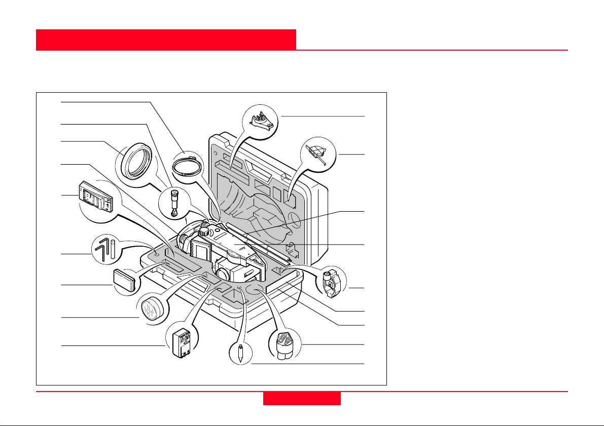
Remove the TPS700 instrument from transport case and check for
completeness:
1
TC700Z31
2
3
4
5
6
7
TC300 jkm kdkjodkolmdlkommlkok
Kurzanleitung
klkoklkodklkdik9 ojokokokdo
8
9
10
11
12
13
14
15
16
17
18
1 Data cable Lemo0/RS232
(optional)
2 Zenith eyepiece or eyepiece for
steep angles (optional)
3 Counterweight for eyepiece for
steep angles (optional)
4 Removable tribrach GDF111/
GDF121 (optional)
5 Battery charger and accessories
(optional)
6 Two Allen keys each, Adjusting
pins
7 Battery GEB111 (optional)
8 Auxiliary lens and filter (optional)
9 Battery GEB121 (optional)
10 Spacing bracket GHT 196 for
instrument height meter (optional)
11 Instrument height meter
GHM 007 (optional)
12 Mini prism rod (optional)
13 Total station
14 Mini prism + holder (optional)
15 Mini target plate (only for TCR
instruments)
16 User Manuals
17 Protective cover / Lens hood
18 Tip for mini prism (optional)
TPS700 User Manual 2.4.0en
15
Measuring Preparation / Setting
Page 16
Power Supply
Use the Leica Geosystems batteries, chargers and
accessories or accessories recommended by Leica
Geosystems to ensure the correct functionality of the
instrument.
Power for the instrument can be supplied either internally
or externally. An external battery is connected to the
instrument using a LEMO cable.
• Internal battery:
One GEB111 or GEB121 battery or the adapter
GAD39 fit in the battery compartment.
• External battery:
One GEB171 battery connected via cable.
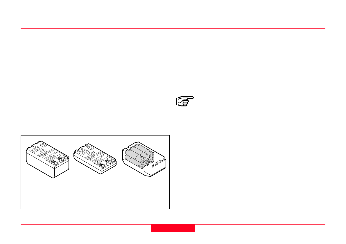
GEB111GEB121 Individual cells in
the battery
adapter GAD39
Your Leica Geosystems instrument is powered by
rechargeable plug-in batteries. For this product, we
recommend the basic battery (GEB111) or the Pro
battery (GEB121). Optionally six single cells can be used
with the GAD39 battery adapter.
Six single cell batteries (1.5 V each) supply 9 Volts. The
voltmeter on the instrument is designed for a voltage of 6
Volts (GEB111/ GEB121).
The battery charge is not displayed correctly
when using single cells. Use the single cells with
the battery adapter as emergency power supply. The
advantage of the single cells is in a lower rate of
discharge even over long periods.
TC700z93
Measuring Preparation / Setting
16
TPS700 User Manual 2.4.0en
Page 17
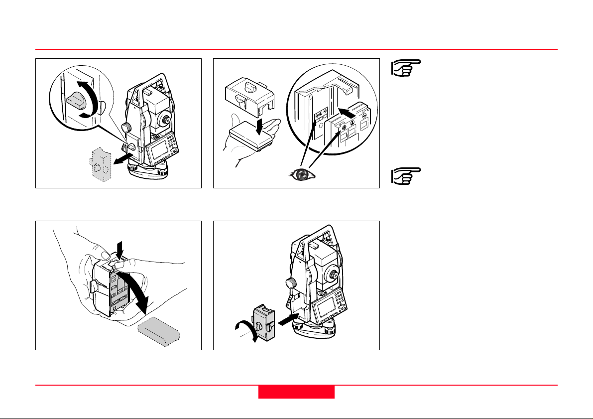
Inserting / Replacing Battery
Insert battery correctly (note
pole markings on the inside
of the battery holder). Check and
insert battery holder true to side into
the housing.
• For type of battery see section
"Technical Data".
TC700Z03TC700Z04
1. Remove battery holder.
3. Insert battery into battery holder.
2. Remove battery and replace. 4. Insert battery holder into
instrument.
TPS700 User Manual 2.4.0en
17
TC700Z05
battery adapter GAD39 for
six individual cells is used, the
spacer for the GEB111 must be
removed from the battery holder
prior to inserting the battery.
If the battery GEB121 or the
TC700Z06
Measuring Preparation / Setting
Page 18

Charging / Discharging Battery
Primary use/charging
• The batteries must be charged prior
to using for the first time because it
is delivered with an energy content
as low as possible.
• For new batteries or batteries that
have been stored for a long time (>
three months), it is effectual to
make 2 - 5 charge/discharge cycles.
• The permissible temperature range
for charging is between 0°C to
+35°C / +32°F to +95°F. For optimal
charging we recommend a low
ambient temperature of +10°C to
+20°C / +50°F to +68°F.
Operation/Discharging
The batteries can be operated from
-20°C to +55°C/-4°F to +131°F.
Low operating temperatures
reduce the capacity that can be
drawn; very high operating
temperatures reduce the service
life of the battery.
Measuring Preparation / Setting
18
TPS700 User Manual 2.4.0en
Page 19
Powering the Total Station from an External Power Supply
To comply with electromagnetic
compatibility (EMC) requirements
when supplying the TPS700
instruments from an external power
supply, it is necessary to fit a socalled ferrite core to the cable used
to connect the instrument to the
external power supply.
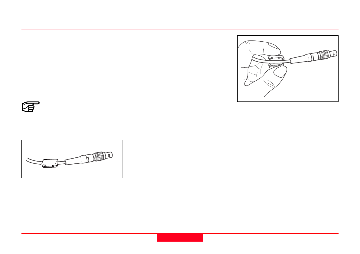
The Lemo connector with
the ferrite core must always
be at the instrument end of the lead.
The cables supplied by Leica
Geosystems are fitted with a ferrite
core as standard. If you intend to use
older cables that are not fitted with a
ferrite core, the cables must be fitted
with a ferrite core prior to use.
You can order ferrite cores from your
Leica Geosystems representative
(spare part number for the ferrite
core: 703707).
TC700Z111
TC700Z112
To fit the core, open it and clip it onto
the cable close to the Lemo
connector before the cable is used
with a TPS700 instrument (approx. 2
cm from the Lemo connector).
TPS700 User Manual 2.4.0en
19
Measuring Preparation / Setting
Page 20
Setting Up the Tripod
TC700Z58
1.
1.
2.
1.
2.
2.
TC700Z19
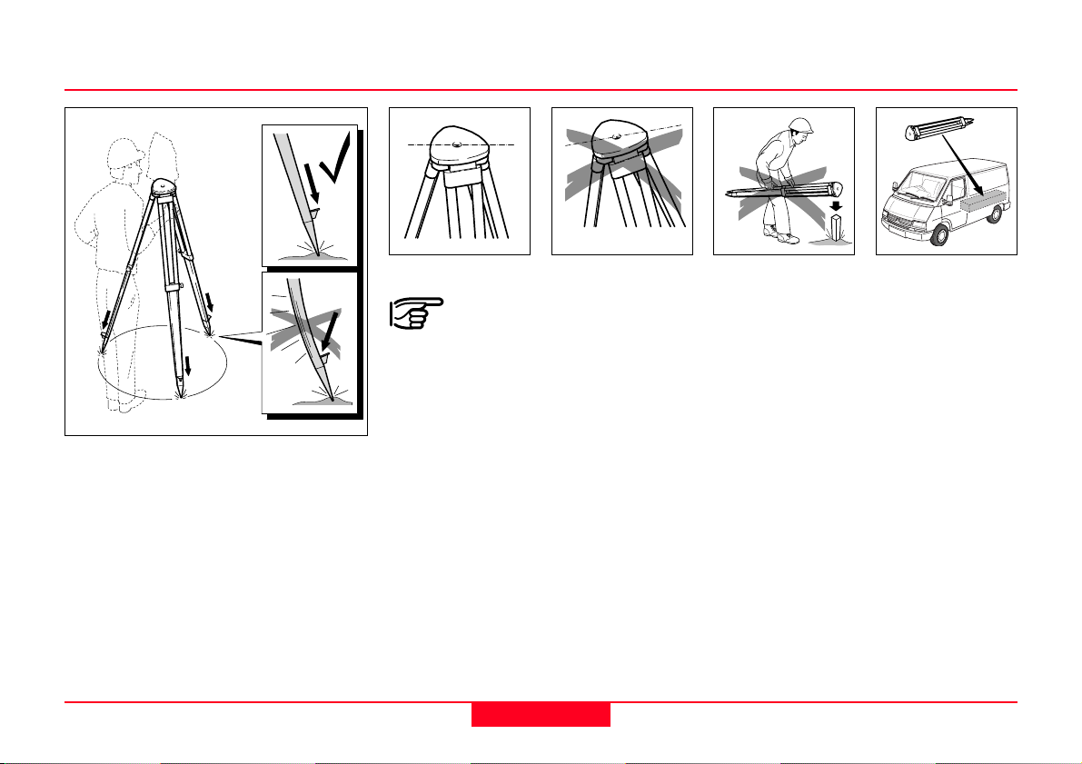
1. Loosen the clamping screws on
the tripod legs, pull out to the
required length and tighten the
screws.
2. In order to guarantee a firm
foothold sufficiently press the
tripod legs into the ground.
When pressing the legs into the
ground note that the force must be
applied along the legs.
Measuring Preparation / Setting
TC700Z32
TC700Z33
When setting up the tripod
pay attention to a horizontal
position of the tripod plate.
Slight corrections of inclination can
be made with the foot screws of the
tribrach. Larger corrections must be
done with the tripod legs .
20
TC700Z57
Careful handling of tripod
• Check all screws and bolts for
correct fit.
• During transport always use the
cover supplied.
• Use the tripod only for surveying
tasks.
TPS700 User Manual 2.4.0en
Page 21
Centering with Laser Plummet / Coarse Level-Up
TC700Z09
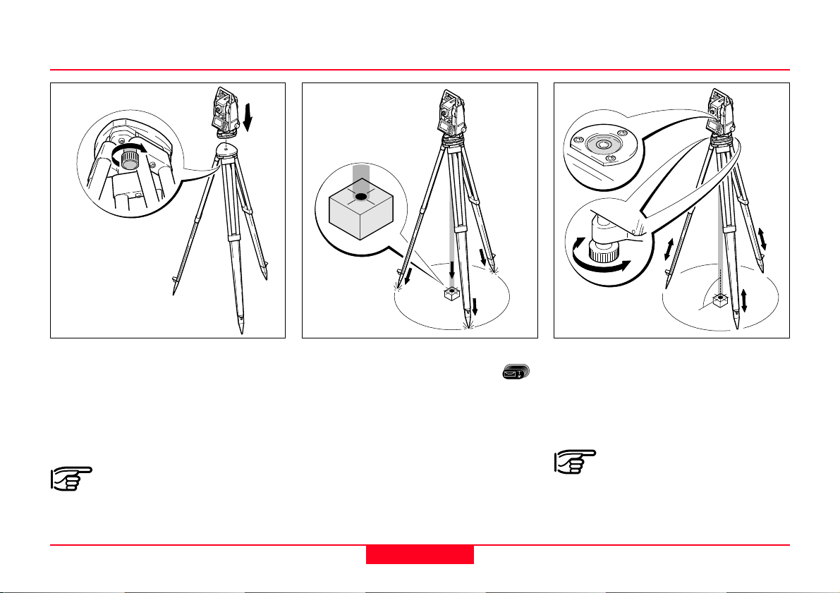
1. Place the instrument onto the
tripod head. Tighten central fixing
screw of tribrach slightly.
2. Turn footscrews of tribrach into its
centre position.
Make sure the tribrach is in
proper working order.
TPS700 User Manual 2.4.0en
TC700Z07
3.
Switch on laser plummet with .
The electronic level appears in the
display.
4. Position tripod legs so that the
laser beam is aimed to the ground
point.
5. Firmly press in tripod legs.
6. Turn the footscrews of the tribrach
to centre the laser beam exactly
over the ground point.
21
TC700Z08
7. Move the tripod legs to centre the
circular level. The instrument is
now roughly levelled-up.
When using a tribrach with
an optical plummet, the
laser plummet cannot be used.
Measuring Preparation / Setting
Page 22
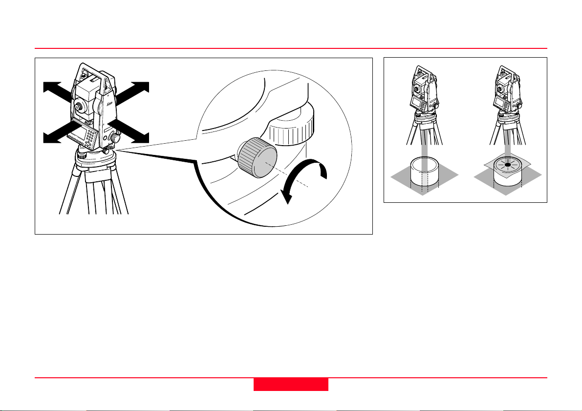
Accurate Levelling-Up with Electronic Level
Laser Intensity
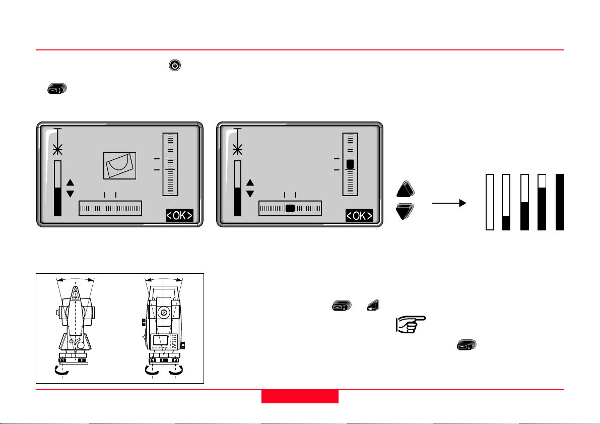
1. Switch instrument on with and
activate electronic plummet with
. If leveling is insufficient, the
symbol of an inclined plummet is
displayed.
20"
20"
2. Center electronic plummet by
turning the foot screws.
If the electronic level is centered the
instrument is levelled-up.
20"
20"
3. Check centring with the laser
plummet and re-centre if
necessary.
4. Switch off the electronic level and
the laser plummet with
or
Changing the laser intensity
External influences and the surface
conditions may require the
adjustment of the intensity of the
laser. The intensity of the laser
plummet can be adjusted in 25%
steps as required.
Min. 50% Max
5. The indicated laser intensity is set,
and the function terminated, with
the <OK> button .
.
Laser plummet and
electronic level are activated
together with
.
Measuring Preparation / Setting
TC700Z10
22
TPS700 User Manual 2.4.0en
Page 23
Centering with Shifting Tribrach
Hints for Positioning
Positioning over pipes or
TC700Z23
depressions
TC700Z35
If the instrument is equipped with a
shifting tribrach it can be aligned to
the ground point by slight shifting.
TPS700 User Manual 2.4.0en
1. Loosen screw.
2. Shift instrument.
3. Fix instrument by turning screw.
23
In some circumstances, the laser
spot is not visible (e.g. over pipes).
In this case, the laser spot can be
made visible by placing a sheet of
semi-transparent material over the
end of the pipe.
Measuring Preparation / Setting
Page 24
Operating the Instrument / Measuring
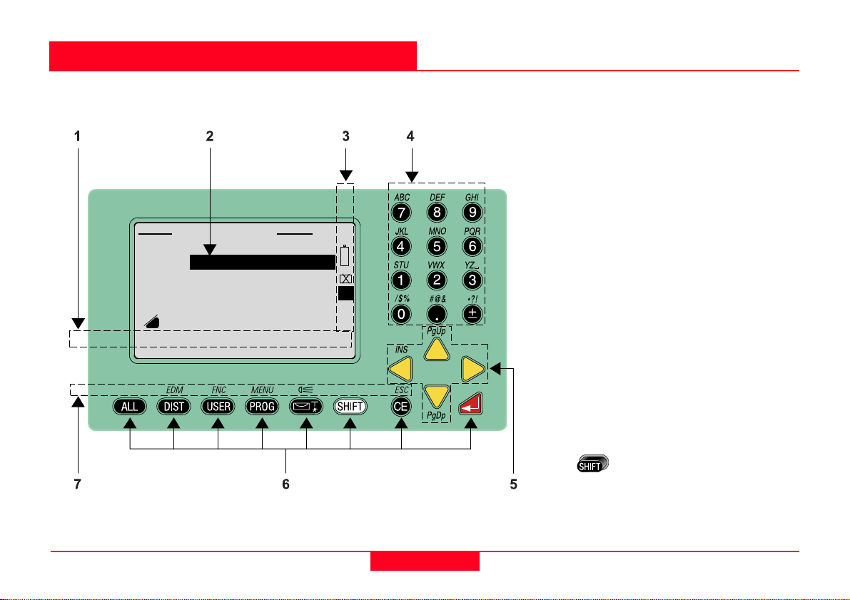
Keypad
MEAS & REC 1/4
PtID : A1
TgHt : 1.500 m
Hz : 50.0000 g
V : 66.6667 g
: -
<SETUP> <Hz0> <QCODE>
---.--- m I
IR
1 Buttons
2 Focus bar
Currently processed field or button
3 Symbols
4 Data entry keys
Entry of numbers, letters, and
special characters
5 Navigation keys
The navigation keys have different
functions depending on the
application.
6 Fixed keys
Keys with permanently defined
functions (e.g. ENTER, SHIFT).
7 Fixed keys - 2nd level
Functions on second key level.
Can be activated by pressing
and the corresponding
fixed keys.
Operating the Instrument / Measuring
24
TPS700 User Manual 2.4.0en
Page 25
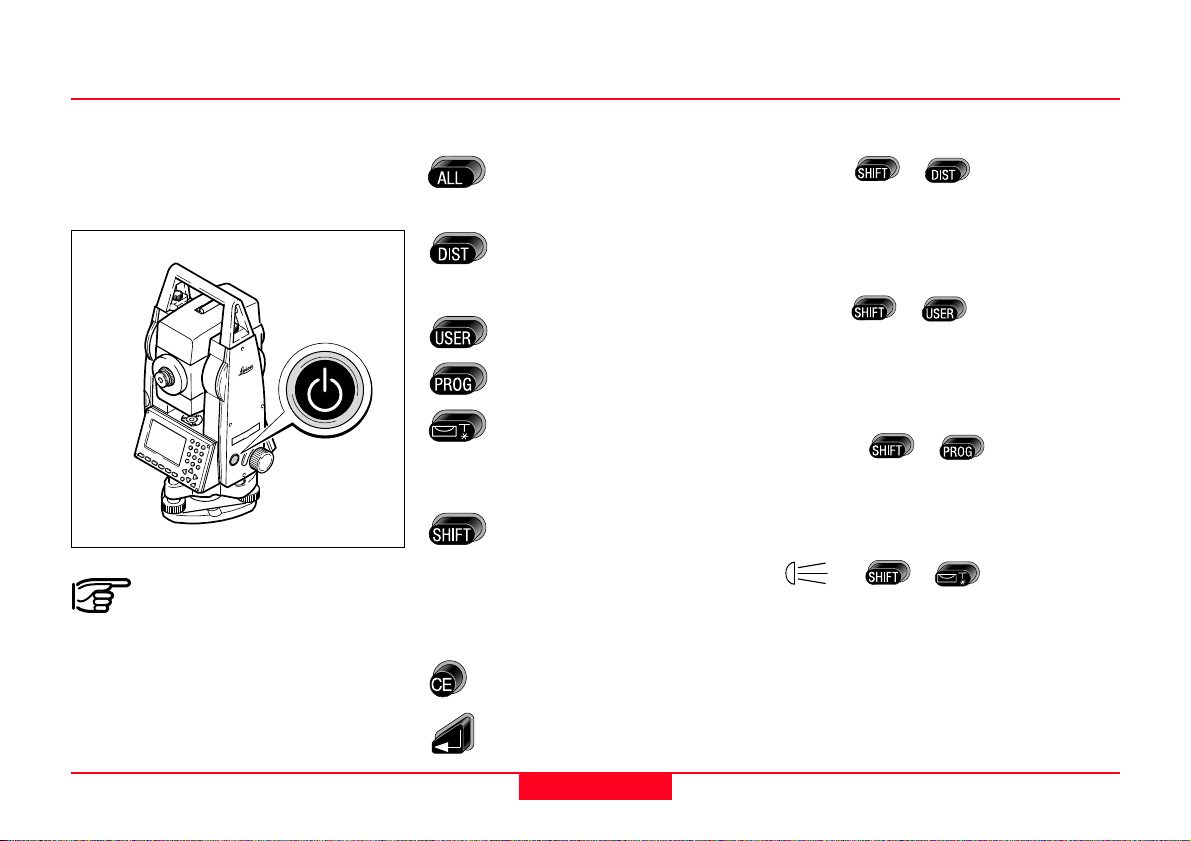
Keypad
The On/Off key is located on the
side cover of the TPS700 instrument
to avoid inadvertently switching the
instrument off.
All displays shown are
examples. Local software
versions may differ from the basic
version.
Fixed keys
TC700Z25
Measure distance and
angles; record measured
values.
Measure distance and
angles; display measured
values without recording.
Key, programmable with
function from the FNC menu.
Starts application programs.
Switches the electronic level
on/off. The laser plummet is
automatically switched on
simultaneously.
Switches to the second key
level (EDM, FNC, MENU,
illumination, ESC) and
switching between
alphanumeric/numeric
character set.
Deletes character/field; stops
EDM.
Fixed keys 2
EDM->
nd
+
level
Access to distance measuring
functions and distance corrections
(ppm).
FNC->
+
Quick-access to measurementsupporting functions.
MENU->
+
Access to Data Manager, instrument
settings and adjustments.
-> +
On/Off switch for display and
crosshairs illumination.
TPS700 User Manual 2.4.0en
Confirms an entry; continue
to the next field.
25
Operating the Instrument / Measuring
Page 26

Keypad
Fixed keys 2nd level
ESC ->
Quit a dialog or the edit mode with
activation of the "previous" value.
Return to next higher level.
PgUp->
"Page Up" = scrolling upwards if
several displays are available in one
dialog.
PgDn->
"Page Down" = scrolling downwards
if several displays are available in
one dialog.
More details can be found in the
Field Manual.
+
+
+
Data entry keys
: Entry of numbers and
letters/special characters.
Entry of the decimal point
and special characters.
Change between positive/
negative sign; entry of
special characters.
When a data entry key is pressed,
the corresponding number is called.
In alphanumeric data entry mode,
each key is used for the entry of 3
letters and a digit.
If the key is repeatedly pressed
quickly, the next character (letter,
special character, number) is called.
If the key is not pressed again within
approximately 1 second, the
character is applied as an entry.
The exact function of these
keys will be covered in more
detail at the appropriate points in the
User Manual.
Navigation keys
( / / / )
The navigation keys can take on a
range of functions depending on the
context in which they are used:
• Control of the focus
• Control of the cursor
• Page through a selection
• Selection and confirmation of
parameters
Operating the Instrument / Measuring
26
TPS700 User Manual 2.4.0en
Page 27

Trigger Key
Buttons
MEAS & REC 1/4
PtID : A1
TgHt : 1.500 m
Hz : 50.0000 g
V : 66.6667 g
: -
<SETUP> <Hz0> <QCODE>
---.--- m I
Important buttons:
<SET> Sets displayed value and
leaves dialog.
IR
<OK> Accepts message displayed
or dialog and leaves dialog.
<EXIT> Leaves a function/
application or menu
prematurely. Changed
values are not set.
Three settings are possible for the
trigger key. It can be assigned the
function or , or it can be
disabled.
The key can be activated in the
configuration menu (More details can
be found in the Field Manual).
TPS700 User Manual 2.4.0en
<SETUP>
TC700Z63
Buttons are a range of commands
appearing in the bottom line of the
display. They can be selected with
the navigation keys and activated
with
available depending on the active
function or application.
. Other buttons may become
27
<PREV> Back to last active dialog.
Menu/application-specific
buttons are explained in the
relevant sections.
Operating the Instrument / Measuring
Page 28

Symbols
Depending on software version different symbols are displayed indicating
a particular operating status.
A double arrow indicates
selection fields.
The desired parameter can be
selected using the navigation keys
.
Selection fields can be quit with
as well as with or .
1/3 Indicates that several pages
are available which can be
selected with
.
I, II Indicates telescope face I or
II
Indicates that Hz is set to "left
side angle measurement"
(anti-clockwise).
Compensator status:
Compensator switched on, 1
axis or 2 axis.
Compensator switched off.
Indicates that ATR is
activated.
and
Status symbol "EDM type"
IR
RL
Status symbol "Battery capacity"
Status symbol "Shift"
Infrared EDM (invisible) for
measuring with prisms and
reflective targets.
Reflectorless EDM (visible)
for measuring with all targets.
The battery symbol indicates
the level of the remaining
battery capacity (75% full
shown in the example).
was pressed or
switching between
alphanumeric /
character set.
numeric
Operating the Instrument / Measuring
28
TPS700 User Manual 2.4.0en
Page 29

User Entries
Entry of numeric values
Numeric fields can contain only
numeric values, the negative sign
and the decimal point. Examples of
numeric fields are: Hz (horizontal
angle), E (Easting), hi (instrument
height).
Numeric values can be entered in
two ways:
1. Enter new value
Replace value displayed by new
value:
Move the focus to the required input
field using the navigation keys
(
and ) Type the numeric
value and the decimal point using
the numeric keys. The sign can be
changed from positive to negative
and vice versa at any time during
data entry using the (±) key.
concludes the entry and the focus
jumps to the next input field.
2. Edit value displayed
Changing only a few digits in the
value displayed:
Move the focus to the required input
field using the navigation keys
(
and ). The key opens
Edit mode and places the cursor on
the character on the extreme right of
the field. The
mode and places the cursor on the
character on the extreme left of the
field. Move the cursor to the
character to be changed using the
and keys. Type the required
digit.
the focus jumps to the next input
field. If the entry is not to be
confirmed, press
old value will be recalled.
concludes the entry and
key opens Edit
and the
TPS700 User Manual 2.4.0en
29
Operating the Instrument / Measuring
Page 30

Entry of Alphanumeric Values
Inserting Characters/Numbers
Alphanumeric fields can contain both
numeric and alphanumeric entries.
Examples of alphanumeric fields are:
PtID, Code, Attribute.
Alphanumeric entries can be made
in two ways as for numeric values:
Make a new entry or edit an existing
entry (for a description see Numeric
Values).
To make it possible to enter
alphanumeric characters (letters,
special characters), the
must be used to switch to the α data
entry mode. The
the display. In a data entry mode,
each key is used to enter 3 letters
and one digit.
icon appears in
key
For example, the key is used to
enter the letters S, T and U.
Press
T, three times for U and four times for
1. If the required letter is missed,
simply keep pressing the key, S
appears again after 1, then T, and so
on. (see section "Character Set").
once to enter S, twice for
When edit mode is active, it is
possible to insert single characters in
existing entries using .
If a character is missed during data
entry, (e.g. 15 instead of 125), then
the missing character can be
inserted later.
1. Position the cursor on the "1" digit
using the / keys.
-15
2. inserts a character (0 in
numeric fields, a space in
alphanumeric fields) to the right of
the "1" digit.
-105
3.
key inserts the required digit.
-125
Operating the Instrument / Measuring
30
4. Confirm entry/change with .
TPS700 User Manual 2.4.0en
Page 31

Deleting Letters/Numbers
When edit mode is active, individual
characters in an entry can be deleted
using the
Example:
1ABC32
The cursor jumps to the next
character. If you press
repeatedly, character after character
is deleted until the input field is
empty.
Pressing
as it was prior to editing.
key.
1AB32
again restores the entry
Numeric values are
displayed in a fixed format
with digits after the decimal point,
even if the digits are zero. Digits after
the decimal point are not deleted by
, but set to zero.
If the focus is on an input
field, but edit mode is not
active, deletes the entire entry.
is pressed again, the old value
If
is restored.
TPS700 User Manual 2.4.0en
31
Operating the Instrument / Measuring
Page 32

Character Set
Numeric
Character Set
Key Numeric Alpha1 Alpha2 Alpha3 Alpha4
0/$%0
. # @ & . ,
+/- ? ! + -
1STU1
2VWX2
3 Y Z [space] 3
4JKL4
5MNO5
6PQR6
7ABC7
8DEF8
9GHI9
Alphanumeric Characters
Alphanumeric Character Set
(Alpha5)
In data fields where searches are
performed for point numbers or
codes, it is also possible to enter the
"*" character
Sign
+/- In the alphanumeric character
set, "+" and "-" are treated as
normal alphanumeric characters.
i.e. they have no mathematical
function.
Special characters
* Place holder for WILDCARD point
searches (see section "Wildcard
Search").
In edit mode, the position of
the decimal point cannot be
changed. The decimal point is skipped.
.
Operating the Instrument / Measuring
32
TPS700 User Manual 2.4.0en
Page 33

Measuring
After switching on and setting up
correctly, the total station is
immediately ready for measuring.
In the measuring display calling all
functions/applications under FNC,
EDM, PROG, MENU, LIGHT, LEVEL
and LASER PLUMMET is possible.
Keep in mind that for all
precision measurements,
the instrument has to adapt to the
ambient temperature and that it has
to be protected from one-sided heat
exposure.
All displays shown are
examples. Local software
versions may differ from the basic
version.
Example of a possible measuring
display:
MEAS & REC 1/4
PtID : A1
TgHt : 1.500 m
Hz : 50.0000 g IR
TC700Z25
V : 66.6667 g
: -
<SETUP> <Hz0> <QCODE>
---.--- m I
Displays
1/4 Indicates further displays with
additional data
,SD, dH, E, N, H, etc).
(e.g.
,
: Changes the display.
<Hz0> Set the Hz-orientation to
0° resp. 0 gon.
When the key is pressed, a
distance measurement is
triggered, then the angle
values are displayed and
both values are either stored
to internal memory or
transmitted via the serial
interface.
Triggers a distance
measurement and displays it.
The displayed distance
remains valid until it is stored
or replaced by a new
measurement.
TPS700 User Manual 2.4.0en
33
Operating the Instrument / Measuring
Page 34

Station Block
This dialog generates a station block
without coordinates which can be
evaluated by software.
In the data output the data is made
available depending on the
evaluation possiblities. The
orientation is manual.
Procedure:
<SETUP>This button in the
measuring display activates
the definition of station and
orientation.
QUICK SETUP. 1/2
Stn : S0
InHt : 1.400 m
BsPt : ------ IR
BsBrg : 50.0000 g
I
<EXIT> <STN.COORD> <SET>
Station:
TC700Z79
The station can be defined with a
station name.
1) Move cursor to "Stn" and enter
station number as well as
instrument height "hi". Close entry
with
.
Orientation:
The orientation is designated with
the number and description of the
target point.
2) Move cursor to "BsPt" and enter
orientation point number. Close
entry with
.
3) Manual input of a Hz value as
orientation.
The orientation is continuously
displayed but can be modified in the
edit mode.
Buttons:
<SET> The entries are registered
and the measuring display
is activated again.
<STN.COORD> Starts manual input
of the station coordinates.
Operating the Instrument / Measuring
34
TPS700 User Manual 2.4.0en
Page 35

Station Block
Manual input of station
coordinates:
Within this dialog, the name, the
height and the station coordinates of
the instrument can be set manually.
<PREV> Back to setup display.
SET STATION
Stn : S0
InHt : 1400 m
EO : 59000.000 m
NO : 44000.000 m
H0 : 500.000 m
<EXIT> <ENH=0> <SET>
1. Move cursor to the required line.
Close entry with .
2. SET>: The entries are registered
and the measuring display is
activated again.
<ENH=0>: The station coordinates
are set to (0/0/0).
<EXIT>: Back to measuring display
without saving.
TPS700 User Manual 2.4.0en
35
Operating the Instrument / Measuring
Page 36

Checking and Adjusting
Tripod
12
The connections between metal and
timber components must always be
firm and tight.
• Tighten the Allen screws (2)
moderately.
• Tighten the articulated joints on
the tripod head (1) just enough to
keep the tripod legs open when
you lift it off the ground.
Circular Level
TC700Z43
Level-up the instrument in advance
with the electronic level. The bubble
must be centered. If it extends
beyond the circle, use the Allen key
supplied to center it by turning the
adjustment screws.
After adjustment no screw must be
loose.
Circular Level on the Tribrach
TC700Z44
Level the instrument and then
remove it from the tribrach. If the
bubble is not centred, adjust it using
the adjusting pin.
Turning the adjustment screws:
• to the left: the bubble approaches
the screw
• to the right: the bubble goes away
from the screw.
After adjustment no screw must be
loose.
TC700Z45
Checking and Adjusting
36
TPS700 User Manual 2.4.0en
Page 37

Laser Plummet
The laser plummet is integrated into
the vertical axis of the instrument.
Under normal circumstances setting
of the laser plummet is not
necessary. If an adjustment is
necessary due to external influences
the instrument has to be returned to
any Leica service department.
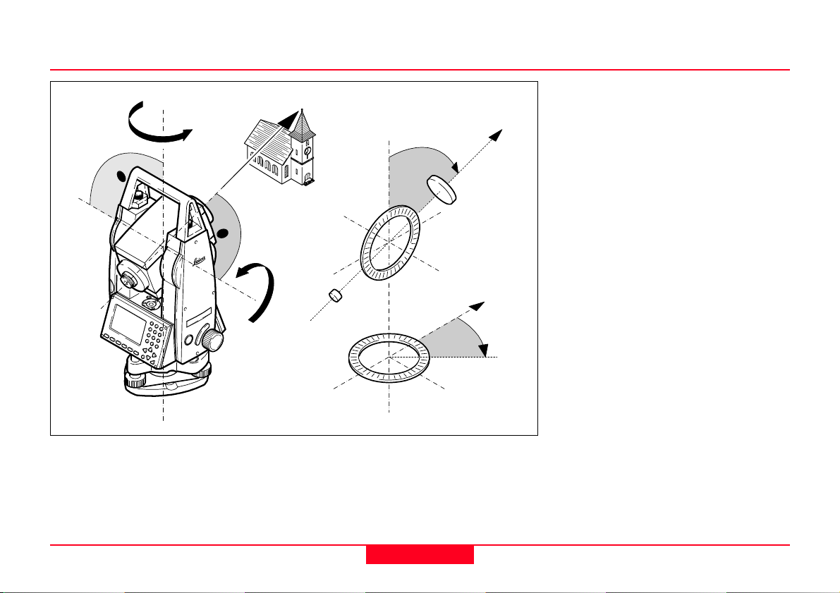
Checking by turning the
instrument by 360°:
1. Install the instrument on the tripod
approx. 1.5 m above ground and
level up.
2. Switch on laser plummet and mark
the centre of the red spot.
3. Turn instrument slowly by 360°
and observe the red laser spot.
Inspecting the laser plummet should
be carried out on a bright, smooth
and horizonal surface (e.g. a sheet
of paper).
1
If the centre of the laser spot makes
a clearly circular movement or if the
centre of the point is moving away
more than 3 mm from the first
marked point an adjustment is
possibly necessary. Call your
nearest Leica service department.
2
360°
Laser spot:
Ø 2.5 mm / 1.5 m
≤ 3 mm / 1.5 m
Depending on brightness and
surface the size of the laser spot can
vary. At a distance of 1.5 m an
average value of 2.5 mm diameter
must be estimated.
The maximum rotation diameter of
the center of the laser spot should
not exceed 3 mm (2 sigma) at a
distance of 1.5 m.
TC700Z20
TPS700 User Manual 2.4.0en
37
Checking and Adjusting
Page 38

Reflectorless EDM
The red laser beam used for
measuring without reflector is
arranged coaxially with the line of
sight of the telescope, and emerges
from the objective port. If the
instrument is well adjusted, the red
measuring beam will coincide with
the visual line of sight. External
influences such as shock or large
temperature fluctuations can
displace the red measuring beam
relative to the line of sight.
The direction of the beam
should be inspected before
precise measurement of distances is
attempted, because an excessive
deviation of the laser beam from the
line of sight can result in inaccurate
distance measurements.
WARNING
For safety aspects direct
intrabeam viewing should be
considered always as hazardous.
Precautions:
Do not stare into the beam or direct it
towards other people unnecessarily.
These measures are also valid for
the reflected beam.
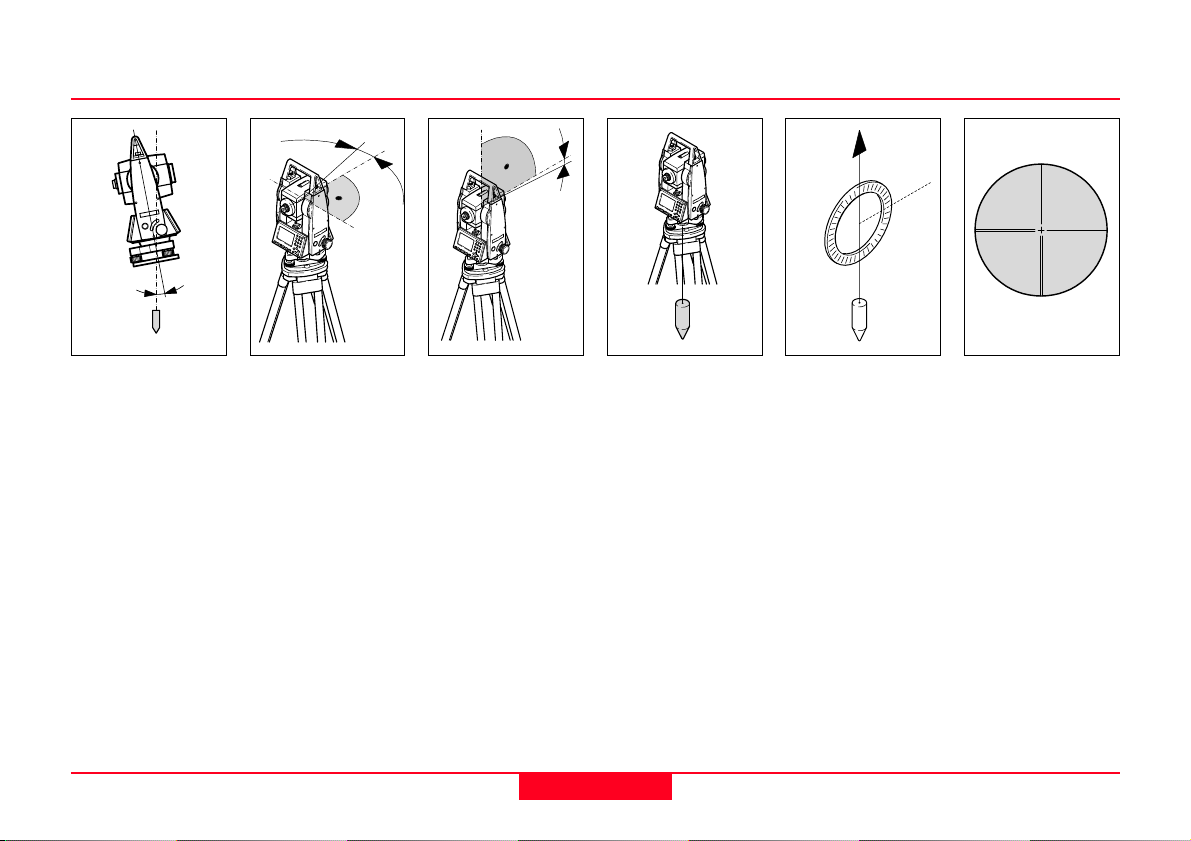
Inspection
A target plate is provided. Set it up
between five and 20 metres away
with the grey reflective side facing
the instrument. Move the telescope
to face II. Switch on the red laser
beam by activating the laser pointer
function. Use the telescope
crosshairs to align the instrument
with the centre of the target plate,
and then inspect the position of the
red laser spot on the target plate.
Generally speaking the red spot
cannot be seen through the
telescope, so look at the target plate
from just above the telescope or
from just to the side of it.
If the spot illuminates the cross, the
achievable adjustment precision has
been reached; if it lies outside the
limits of the cross, the direction of the
beam needs to be adjusted.
If the spot on the more reflective side
of the plate is too bright (dazzling),
use the white side instead to carry
out the inspection.
TC700Z88
Checking and Adjusting
38
TPS700 User Manual 2.4.0en
Page 39

Reflectorless EDM
Adjusting the Direction of the Beam
Turn the telescope in such a way
that the two plugs are on the top
side. Pull the two plugs out from the
adjustment ports.
To correct the height of the beam,
insert the screwdriver into the
adjustment port (1) and turn it
clockwise (spot on target plate
moves obliquely upwards) or
anticlockwise (spot moves obliquely
downwards).
To correct the beam laterally, insert
the screwdriver into the adjustment
port (2) and turn it clockwise (spot
moves to the right) or anticlockwise
(spot moves to the left).
TC700Z51
Throughout the adjustment
procedure, keep the
telescope pointing to the target plate.
After each field adjustment,
close adjustment ports again
to keep out damp and dirt.
1
2
TC700Z52
TPS700 User Manual 2.4.0en
39
Checking and Adjusting
Page 40

Care and Storage
Transport
When transporting or shipping the
equipment always use the original
Leica Geosystems packaging
(transport case and shipping
cardboard).
After a longer period of
storage or transport of your
instrument always check the field
ajustment parameters indicated in
this manual before using the
instrument.
Maintainance for motorized drives
An inspection of the drives in
TCRApower or TCRAultra
instruments must be done in a Leica
Geosystems service shop:
• After about 4000 hours operation
• Twice a year in case of permanent
use of the instrument (e.g. in
monitoring applications)
In the Field
When transporting the equipment in
the field, always make sure to
• either carry the instrument in its
original transport case or,
TC700Z21
• carry the tripod with its legs
splayed across your shoulder,
keeping the attached instrument
upright.
TC700Z36
Care and Storage
40
TPS700 User Manual 2.4.0en
Page 41

Inside Vehicle Shipping
TC700Z70
TC700Z71
Never transport the instrument loose
inside the vehicle.
The instrument can be damaged by
blows and vibrations. It must always
be transported in its case and be
properly secured.
TPS700 User Manual 2.4.0en
For shipping the instrument by rail,
aircraft or ship use the Leica
Geosystems original packaging
(transport case or shipping
cardboard) or another suitable
packaging securing the instrument
against blows and vibrations.
41
Care and Storage
Page 42

Storage
TC700Z61
When storing the
equipment, particularly in
summer and inside a vehicle, take
the temperature limits into account.
When storing the intrument inside a
building also use the transport case
(if possible, in a safe place).
NiMH and Alkaline batteries
• The permissible temperature
range for storing is -40°C to +55°C
/ -40°F to +131°F. A storage
temperature range of 0°C to
+20°C / +32°F to +68°F in dry
environment is recommended to
minimize self-discharging of the
battery.
• At the recommended storage
temperature range, batteries
containing a 10% to 50% charge
can be stored for up to one year.
After this storage period the
batteries must be recharged.
• Remove batteries from the
product and the charger before
storing.
• After storage recharge batteries
(NiMH) before using.
• Protect batteries from damp and
wetness. Wet or damp batteries
must be dried before storing or
use.
TC700Z66
If the instrument becomes
wet, please unpack.
Wipe down, clean, and dry the
instrument (at not more than 40 °C/
104°F), transport case, foam inserts,
and accessories. Pack up the
equipment only when it is perfectly
dry.
When using the instrument in the
field always close the transport case.
Care and Storage
42
TPS700 User Manual 2.4.0en
Page 43

Cleaning
TC700Z67
TC700Z50
Objective, eyepiece and
prisms:
• Blow dust off lenses and prisms.
• Never touch the glass with fingers.
• Use only a clean, soft and lint-free
cloth for cleaning. If necessary,
moisten the cloth with pure
alcohol.
Use no other liquids; these may
attack polymer components.
TPS700 User Manual 2.4.0en
Fogging of prisms:
Reflector prisms that are
cooler than the ambient temperature
tend to fog. It is not enough simply to
wipe them. Keep them for some time
inside your jacket or in the vehicle to
allow them to adjust to the ambient
temperature.
Cables and plugs:
Make sure plugs do not get
dirty and are protected against
moisture. Blow clean all dirty plugs. If
connecting cables are disconnected
while measuring, data may be lost.
Only remove connecting cables after
the instrument has been turned off.
43
Care and Storage
Page 44

Safety Directions
Intended Use
The following directions should
enable the person responsible for
the product and the person who
actually uses the equipment, to
anticipate and avoid operational
hazards.
The person responsible for the
product must ensure that all users
understand these directions and
adhere to them
Permitted use
• Measuring horizontal and vertical
angles
• Measuring distances
• Recording measurements
• Computing by means of
application software
• Automatic target recognition (with
ATR)
• Visualizing the aiming direction
(with EGL)
• Visualizing the vertical axis (with
the laser plummet).
Prohibited use
• Use of the product without
instruction
• Use outside of the intended limits
• Disabling safety systems
• Removal of hazard notices
• Opening the product using tools
(screwdriver, etc.), unless this is
specifically permitted for certain
functions
• Modification or conversion of the
product
• Use after misappropriation
• Use of products with obviously
recognizable damages or defects.
• Use with accessories from other
manufacturers without the prior
express approval of Leica Geosystems
• Aiming directly into the sun
• Inadequate safeguards at the
measuring station (e.g. when
measuring on roads)
Safety Directions
44
TPS700 User Manual 2.4.0en
Page 45

Prohibited uses
Limits of Use
• Controlling machines, or
controlling moving objects or
similar, with the automatic target
recognition ATR or with the visible
EDM.
• Deliberate dazzling of third parties
WARNING
Adverse use can lead to
injury, malfunction and
damage. It is the task of the person
responsible for the equipment to
inform the user about hazards and
how to counteract them. The product
is not to be operated until the user
has been instructed on how to work
with it.
Environment
Suitable for use in an atmosphere
appropriate for permanent human
habitation: not suitable for use in
aggressive or explosive
environments.
DANGER
Local safety authorities and
safety experts must be
contacted before working in
hazardous areas, or in close
proximity to electrical installations or
similar situations by the person in
charge of the product.
TPS700 User Manual 2.4.0en
45
Safety Directions
Page 46

Responsibilities
Manufacturer of the product
Leica Geosystems AG, CH-9435
Heerbrugg, hereinafter referred to as
Leica Geosystems, is responsible for
supplying the product, including the
user manual and original
accessories, in a completely safe
condition.
Manufacturer of non Leica
Geosystems accessories
The manufacturers of non Leica
Geosystems accessories for the
product are responsible for
developing, implementing and
communicating safety concepts for
their products, and are also
responsible for the effectiveness of
those safety concepts in combination
with the Leica Geosystems product.
Person in charge of the product
The person in charge of the product
has the following duties:
• To understand the safety
instructions on the product and the
instructions in the user manual.
• To be familiar with local
regulations relating to safety and
accident prevention.
• To inform Leica Geosystems
immediately if the product and the
application becomes unsafe.
WARNING
The person responsible for
the product must ensure that
it is used in accordance with the
instructions. This person is also
accountable for the training and the
deployment of personnel who use
the product and for the safety of the
equipment in use.
Safety Directions
46
TPS700 User Manual 2.4.0en
Page 47

International Warranty, Software Licence Agreement
International Warranty
The International Warranty can be
downloaded from the Leica
Geosystems home page at http://
www.leica-geosystems.com/
internationalwarranty or received
from your Leica Geosystems dealer.
Software Licence Agreement
This product contains software that is
preinstalled on the product, or that is
supplied to you on a data carrier
medium, or that can be downloaded
by you online pursuant to prior
authorization from Leica
Geosystems. Such software is
protected by copyright and other
laws and its use is defined and
regulated by the Leica Geosystems
Software Licence Agreement, which
covers aspects such as, but not
limited to, Scope of the Licence,
Warranty, Intellectual Property
Rights, Limitation of Liability,
Exclusion of other Assurances,
Governing Law and Place of
Jurisdiction. Please make sure, that
at any time you fully comply with the
terms and conditions of the Leica
Geosystems Software Licence
Agreement.
Such agreement is provided together
with all products and can also be
found at the Leica Geosystems
home page at http://www.leicageosystems.com/swlicense or your
Leica Geosystems dealer.
You must not install or use the
software unless you have read and
accepted the terms and conditions of
the Leica Geosystems Software
Licence Agreement. Installation or
use of the software or any part
thereof, is deemed to be an
acceptance of all the terms and
conditions of such licence
agreement. If you do not agree to all
or some of the terms of such licence
agreement, you may not download,
install or use the software and you
must return the unused software
together with its accompanying
documentation and the purchase
receipt to the dealer from whom you
purchased the product within ten
(10) days of purchase to obtain a full
refund of the purchase price.
TPS700 User Manual 2.4.0en
47
Safety Directions
Page 48

Hazards of Use
WARNING
The absence of instruction,
or the inadequate imparting
of instruction, can lead to incorrect or
adverse use, and can give rise to
accidents with far-reaching human,
material, financial, and
environmental consequences.
Precautions:
All users must follow the safety
directions given by the manufacturer
and the directions of the person
responsible for the product.
WARNING
Using a battery charger not
recommended by Leica
Geosystems can destroy the
batteries. This can cause fire or
explosions.
Precautions:
Only use chargers recommended by
Leica Geosystems to charge the
batteries.
CAUTION
Watch out for erroneous
measurement results if the
product has been dropped or has
been misused, modified, stored for
long periods or transported.
Precautions:
Periodically carry out test
measurements and perform the field
adjustments indicated in the user
manual, particularly after the product
has been subjected to abnormal use
and before and after important
measurements.
DANGER
Because of the risk of
electrocution, it is very
dangerous to use poles and
extensions in the vicinity of electrical
installations such as power cables or
electrical railways.
Precautions:
Keep at a safe distance from
electrical installations. If it is
essential to work in this environment,
first contact the safety authorities
responsible for the electrical
installations and follow their
instructions.
Safety Directions
48
TPS700 User Manual 2.4.0en
Page 49

Hazards of Use
WARNING
By surveying during a
thunderstorm you are at risk
from lightning.
Precautions:
Do not carry out field surveys during
thunderstorms.
CAUTION
Be careful when pointing the
product towards the sun,
because the telescope functions as a
magnifying glass and can injure your
eyes and/or cause damage inside
the product.
Precautions:
Do not point the product directly at
the sun.
WARNING
During dynamic
applications, for example
stakeout procedures there is a
danger of accidents occurring if the
user does not pay attention to the
environmental conditions around, for
example obstacles, excavations or
traffic.
Precautions:
The person responsible for the
product must make all users fully
aware of the existing dangers.
WARNING
Inadequate securing of the
surveying site can lead to
dangerous situations, for example in
traffic, on building sites, and at
industrial installations.
Precautions:
Always ensure that the survey site is
adequately secured. Adhere to the
regulations governing safety and
accident prevention and road traffic.
TPS700 User Manual 2.4.0en
49
Safety Directions
Page 50

Hazards of Use
WARNING
If computers intended for
use indoors are used in the
field there is a danger of electric
shock.
Precautions:
Adhere to the instructions given by
the computer manufacturer with
regard to field use in conjunction with
Leica Geosystems products.
CAUTION
During the transport,
shipping or disposal of batteries it is
possible for inappropriate
mechanical influences to constitute a
fire hazard.
Precautions:
Before shipping the product or
disposing of it, discharge the
batteries by running the product until
they are flat.
When transporting or shipping
batteries, the person in charge of the
product must ensure that the
applicable national and international
rules and regulations are observed.
Before transportation or shipping
contact your local passenger or
freight transport company.
WARNING
High mechanical stress,
high ambient temperatures
or immersion into fluids can cause
leackage, fire or explosions of the
batteries.
Precautions:
Protect the batteries from
mechanical influences and high
ambient temperatures. Do not drop
or immerse batteries into fluids.
CAUTION
If the accessories used with
the product are not properly
secured and the product is subjected
to mechanical shock, for example
blows or falling, the product may be
damaged or people may sustain
injury.
Precautions:
When setting-up the product, make
sure that the accessories, for
example tripod, tribrach, connecting
cables, are correctly adapted, fitted,
secured, and locked in position.
Avoid subjecting the product to
mechanical stress.
Safety Directions
50
TPS700 User Manual 2.4.0en
Page 51

Hazards of Use
WARNING
If the product is improperly
disposed of, the following
can happen:
• If polymer parts are burnt,
poisonous gases are produced
which may impair health.
• If batteries are damaged or are
heated strongly, they can explode
and cause poisoning, burning,
corrosion, or environmental
contamination.
• By disposing of the product
irresponsibly you may enable
unauthorized persons to use it in
contravention of the regulations,
exposing themselves and third
parties to the risk of severe injury
and rendering the environment
liable to contamination.
• Improper disposal of silicone oil
may cause environmental
contamination.
Precautions:
The product must not be
disposed with household
waste.
Dispose of the product appropriately
in accordance with the national
regulations in force in your country.
Always prevent access to the
product by unauthorized personnel.
Product specific treatment and waste
management information can be
downloaded from the Leica
Geosystems home page at
http://www.leica-geosystems.com/
treatment or received from your
Leica Geosystems dealer.
CAUTION
Only Leica Geosystems
authorized workshops are
entitled to repair these products.
TPS700 User Manual 2.4.0en
51
Safety Directions
Page 52

Laser Classification
Integrated Distancer, Invisible Laser
The EDM module built into the
product produces an invisible laser
beam which emerges from the
telescope objective.
The product is a Class 1 Laser
Product in accordance with:
• IEC 60825-1 (2001-08): "Safety of
Laser Products".
• EN 60825-1:1994 + A11:1996 +
A2:2001: "Safety of Laser
Products".
Class 1 Laser Products are safe
under reasonably foreseeable
conditions of operation and are not
harmful to the eyes provided that the
products are used and maintained in
accordance with the instructions.
Description Value
Beam divergence 1.8 mrad
Pulse duration 800 ps
Pulse repetition frequency 100 MHz
Maximum average radiant power 0.33 mW +
Maximum peak radiant power 4.12 mW +
Labelling
Type: TC.... Art.No.: ......
Power: 12V/6V ---, 1A max
Leica Geosystems AG
CH-9435 Heerbrugg
Manufactured: 2005
Made in Switzerland S.No.: ......
Complies with 21 CFR 1040.10 and 1040.11
except for deviations pursuant to Laser Notice
No.50, dated July 26,2001.
This device complies with part 15 of the FCC
Rules. Operation is subject to the following two
conditions: (1) This device may not cause harmful interference, and (2) this device must accept
any interference received, including interference that may cause undesired operation.
Class 1 Laser Product
according to IEC 60825-1
(2001-08)
a
a) Laser beam
5 %
5 %
TC700Z113
Safety Directions
52
TPS700 User Manual 2.4.0en
Page 53

Integrated Distancer, Visible Laser
As an alternative to the invisible laser, the EDM incorporated into the product produces a visible red laser beam
which emerges from the telescope objective.
WARNING
The two types R100 and R300 of distancers with visible laser are available, identifiable by the type plate.
The products are Class 3R Laser Products in accordance with:
• IEC 60825-1 (2001-08): "Safety of Laser Products".
• EN 60825-1:1994 + A11:1996 + A2:2001: "Safety of Laser Products".
Class 3R Laser Products:
For safety aspects direct intrabeam viewing should be considered always as hazardous. Avoid direct eye exposure.
The accessible emission limit is within five times the accessible emission limits of Class 2 in the wavelength range
from 400 nm to 700 nm.
Description R100 R300
Maximum average radiant power 4.75 mW +
Maximum peak radiant power 59 mW +
Pulse duration 800 ps 800 ps
Pulse repetition frequency 10 0 MHz 100 MHz - 150 MHz
Beam divergence 0.15 x 0.35 mrad 0.15 x 0.5 mrad
5% 4.75 mW + 5%
5% 59 mW + 5%
TPS700 User Manual 2.4.0en
53
Safety Directions
Page 54

Integrated Distancer, Visible Laser
WARNING
For safety aspects direct
intrabeam viewing should be
considered always as hazardous.
Precautions:
Do not stare into the beam or direct it
towards other people unnecessarily.
These measures are also valid for
the reflected beam.
WARNING
Looking directly into the
reflected laser beam could
be dangerous to the eyes when the
laser beam is aimed at areas that
reflect like a mirror or emit reflections
unexpectedly, for example prisms,
mirrors, metallic surfaces or
windows.
Precautions:
Do not aim at areas that are
essentially reflective, such as a
mirror, or which could emit unwanted
reflections. Do not look through or
beside the optical sight at prisms or
reflecting objects when the laser is
switched on, in Laserpointer or
distance measurement mode. Aiming
at prisms is only permitted when
looking through the telescope.
WARNING
The use of Laser Class 3R
equipment can be
dangerous.
Precautions:
To counteract hazards, it is essential
for every user to respect the safety
precautions and control measures
specified in the standard
IEC 60825-1 (2001-08) resp. EN
60825-1:1994 + A11:1996 +
A2:2001, within the hazard distance
*); pay particular attention to Section
Three "User's Guide".
Safety Directions
54
TPS700 User Manual 2.4.0en
Page 55

Integrated Distancer, Visible Laser
Following an interpretation of the
main points in the relevant section of
the standard quoted.
Class 3R Laser Products used on
construction sites and outdoors, for
example surveying, alignment,
levelling:
a) Only qualified and trained persons
should be assigned to install,
adjust and operate the laser
equipment.
b) Areas in which these lasers are
used should be posted with an
appropriate laser warning sign.
c) Precautions should be taken to
ensure that persons do not look
directly, with or without an optical
instrument, into the beam.
d) The laser beam should be
terminated at the end of its useful
beam path and should in all cases
be terminated if the hazardous
beam path extends beyond the
limit (hazard distance *)) of the
area in which the presence and
activities of personnel are
monitored for reasons of
protection from laser radiation.
e) The laser beam path should be
located well above or below eye
level wherever practicable.
f) When not in use the Laser
Product should be stored in a
location where unauthorized
personnel cannot gain access.
g) Precautions should be taken to
ensure that the laser beam is not
unintentionally directed at mirrorlike, specular surfaces, for
example mirrors, metal surfaces
or windows. But, more importantly,
at flat or concave mirror-like
surfaces.
*) The hazard distance is the
distance from the laser at which
beam irradiance or radiant
exposure equals the maximum
permissible value to which
personnel may be exposed
without being exposed to a health
risk.
Products with an integrated distancer
of laser class 3R this hazard
distance is 68 m / 224 ft. At this
distance, the laser beam rates as
Class 1M, that means direct
intrabeam viewing is not hazardous.
TPS700 User Manual 2.4.0en
55
Safety Directions
Page 56

Integrated Distancer, Visible Laser
Labelling
Laser Aperture
a
Laser Radiation
Avoid direct eye exposure
Class 3R Laser Product
according to IEC 60825-1
( 2001 - 08 )
≤ 4.75 mW
P
0
λ = 650 - 690 nm
Type: TC.... Art.No.: ......
Power: 12V/6V ---, 1A max
Leica Geosystems AG
CH-9435 Heerbrugg
TC700Z110
Manufactured: 2005
Made in Switzerland S.No.: ......
Complies with 21 CFR 1040.10 and 1040.11
except for deviations pursuant to Laser Notice
No.50, dated July 26,2001.
This device complies with part 15 of the FCC
Rules. Operation is subject to the following two
conditions: (1) This device may not cause harmful interference, and (2) this device must accept
any interference received, including interference that may cause undesired operation.
TC700Z54
a) Laser beam
Safety Directions
56
TPS700 User Manual 2.4.0en
Page 57

Automatic Target Recognition (ATR)
The integrated automatic target recognition produces an
invisible laser beam which emerges from the telescope
objective.
The product is a Class 1 Laser Product in accordance
with:
• IEC 60825-1 (2001-08): "Safety of Laser Products".
• EN 60825-1: 1994 + A11:1996 + A2:2001:"Safety of
Laser Products".
Class 1 Laser Products are safe under reasonably
foreseeable conditions of operation and are not harmful
to the eyes provided that the products are used and
maintained in accordance with the instructions.
Description Value
Maximum average radiant power 1 mW ± 5%
Maximum peak radiant power 2 mW ± 5%
Pulse duration 9.8 ms
Pulse repetition frequency 50 Hz
Beam divergence 26.2 mrad
Labelling
Type: TC.... Art.No.: ......
Power: 12V/6V ---, 1A max
Leica Geosystems AG
CH-9435 Heerbrugg
Manufactured: 2005
Made in Switzerland S.No.: ......
Complies with 21 CFR 1040.10 and 1040.11
except for deviations pursuant to Laser Notice
No.50, dated July 26,2001.
This device complies with part 15 of the FCC
Rules. Operation is subject to the following two
conditions: (1) This device may not cause harmful interference, and (2) this device must accept
any interference received, including interference that may cause undesired operation.
TC700Z113
a) Laser beam
Class 1 Laser Product
according to IEC 60825-1
(2001-08)
a
TPS700 User Manual 2.4.0en
57
Safety Directions
Page 58

Electronic Guide Light EGL
The integrated electronic guide light
produces a visible LED beam from
the front side of the telescope.
Depending on the type of telescope
the EGL may be designed differently.
The product is a Class 1 LED
product in accordance with:
• IEC 60825-1 (2001-08): "Safety of
Laser Products".
• EN 60825-1:1994 + A11:1996 +
A2:2001: "Safety of Laser
Products".
Class 1 LED products are safe under
reasonably foreseeable conditions of
operation and are not harmful to the
eyes provided that the products are
used and maintained in accordance
with the instructions.
Flashing LED Yellow Red
Maximum average radiant power 0.28 mW ± 5 % 0.47 mW ± 5 %
Maximum peak radiant power 0.75 mW ± 5 % 2.5 mW ± 5 %
Pulse duration 2 x 10⁵ ms 1 x 10⁵ ms
Pulse repetition frequency 1.786 Hz 1.786 Hz
Beam divergence 2.4 ° 2.4 °
Labelling
Type: TC.... Art.No.: ......
Power: 12V/6V ---, 1A max
Leica Geosystems AG
CH-9435 Heerbrugg
Manufactured: 2005
Made in Switzerland S.No.: ......
Complies with 21 CFR 1040.10 and 1040.11
except for deviations pursuant to Laser Notice
No.50, dated July 26,2001.
This device complies with part 15 of the FCC
Rules. Operation is subject to the following two
conditions: (1) This device may not cause harmful interference, and (2) this device must accept
any interference received, including interference that may cause undesired operation.
Class 1 LED Product
according to IEC 60825-1
(2001-08)
a
b
TC700Z114
Safety Directions
a) LED beam red
b) LED beam yellow
58
TPS700 User Manual 2.4.0en
Page 59

Laser Plummet
The laser plummet built into the product produces a
visible red laser beam which emerges from the bottom of
the product.
The product is a Class 2 Laser Product in accordance
with:
• IEC 60825-1 (2001-08): "Safety of Laser Products".
• EN 60825-1:1994 + A11:1996 + A2:2001: "Safety of
Laser Products".
Class 2 Laser Products:
Do not stare into the beam or direct it unnecessarily at
other persons. Eye protection is normally afforded by
aversion responses including the blink reflex.
Description Value
Maximum average radiant power 0.95 mW ± 5%
Pulse duration c.w.
Beam divergence 0.16 x 0.6 mrad
WARNING
It can be dangerous to look into the beam with
optical equipment, for example binoculars or
telescopes.
Precautions:
Do not look directly into the beam with optical equipment.
TPS700 User Manual 2.4.0en
59
Safety Directions
Page 60

Laser Plummet
Labelling
Type: TC.... Art.No.: ......
Power: 12V/6V ---, 1A max
Leica Geosystems AG
CH-9435 Heerbrugg
Manufactured: 2005
Made in Switzerland S.No.: ......
Complies with 21 CFR 1040.10 and 1040.11
except for deviations pursuant to Laser Notice
No.50, dated July 26,2001.
This device complies with part 15 of the FCC
Rules. Operation is subject to the following two
conditions: (1) This device may not cause harmful interference, and (2) this device must accept
any interference received, including interference that may cause undesired operation.
Laser Radiation
Do not stare into beam
Class 2 Laser Product
a
according to IEC 60825-1
(2001 - 08)
≤ 0.95 mW
P
0
λ = 620 - 690 nm
a) Will be replaced by a Class 3R warning label if applicable
Safety Directions
60
ab
TC700Z55
TC700Z56
a) Laser beam
b) Exit for laser beam
TPS700 User Manual 2.4.0en
Page 61

Electromagnetic Compatibility EMC
The term "electromagnetic
compatibility" is taken to mean the
capability of the instrument to
function correctly in an environment
where electromagnetic radiation and
electrostatic discharges are present,
and without causing electromagnetic
disturbances in other equipment.
WARNING
Electromagnetic radiation
can cause disturbances in
other equipment.
Although the product meets the strict
regulations and standards which are
in force in this respect, Leica
Geosystems cannot completely
exclude the possibility that other
equipment may be disturbed.
CAUTION
There is a risk that
disturbances may be
caused in other equipment if the
product is used in conjunction with
accessories from other
manufacturers, for example field
computers, personal computers, twoway radios, non-standard cables or
external batteries.
Precautions:
Use only the equipment and
accessories recommended by Leica
Geosystems. When combined with
the product, they meet the strict
requirements stipulated by the
guidelines and standards. When
using computers and two-way
radios, pay attention to the
information about electromagnetic
compatibility provided by the
manufacturer.
CAUTION
Disturbances caused by
electromagnetic radiation
can result in erroneous
measurements.
Although the product meets the strict
regulations and standards which are
in force in this respect, Leica
Geosystems cannot completely
exclude the possibility that the
product may be disturbed by very
intense electromagnetic radiation, for
example, near radio transmitters,
two-way radios or diesel generators.
Precautions:
Check the plausibility of results
obtained under these conditions.
TPS700 User Manual 2.4.0en
61
Safety Directions
Page 62

Electromagnetic Compatibility EMC
WARNING
If the product is operated
with connecting cables
attached at only one of their two
ends, for example external supply
cables, interface cables, the
permitted level of electromagnetic
radiation may be exceeded and the
correct functioning of other
instruments may be impaired.
Precautions:
While the product is in use,
connecting cables, for example
product to external battery, product
to computer, must be connected at
both ends.
Safety Directions
62
TPS700 User Manual 2.4.0en
Page 63

FCC Statement, Applicable in U.S.
WARNING
This equipment has been tested and found to
comply with the limits for a Class B digital
device, pursuant to part 15 of the FCC Rules.
These limits are designed to provide reasonable
protection against harmful interference in a residential
installation.
This equipment generates, uses and can radiate
frequency energy and, if not installed and used in
accordance with the instructions, may cause harmful
interference to radio communications.
However, there is no guarantee that interference will not
occur in a particular installation.
If this equipment does cause harmful interference to
radio or television reception, which can be determined by
turning the equipment off and on, the user is encouraged
to try to correct the interference by one or more of the
following measures:
• Reorient or relocate the receiving antenna.
• Increase the separation between the equipment and
receiver.
• Connect the equipment into an outlet on a circuit
different from that to which the receiver is connected.
• Consult the dealer or an experienced radio/TV
technician for help.
WARNING
Changes or modifications not expressly
approved by Leica Geosystems for compliance
could void the user's authority to operate the equipment.
Product labelling:
........ ..............
. . . . . . . .
. . . . . . . . . . . . . . . . . . . . .
. . . . . . . . . . . . . . . . . . . . .
. . . . . . . . . . . . . . . . .
. . . . . . . . . . . . . . . . . . . . . .
. . . . . . . . . . . . . . . . . . .
This device complies with part 15 of the FCC
Rules. Operation is subject to the following two
conditions: (1) This device may not cause harmful interference, and (2) this device must accept
any interference received, including interference that may cause undesired operation.
TC700Z54a
TPS700 User Manual 2.4.0en
63
Safety Directions
Page 64

Technical Data
Telescope
• Transits fully
• Magnification: 30x
• Image: upright
• Free objective aperture: 40 mm
• Shortest focussing
distance: 1.7 m (5.6 ft)
• Focusing: fine
• Field of view: 1°30' (1.7gon)
• Telescope field of view
at 100 m 2.6 m
Angle measurement
• absolute, continuous,
• Units selectable
360° sexagesimal, 400gon,
360° decimal, 6400 mil, V%, ±V
• Accuracy standard deviation Hz, V
(acc. to ISO17123-3)
Type 702 2" (0.6 mgon)
Type 703 3" (1 mgon)
Type 705 5" (1.5 mgon)
• Smallest display resolution
gon: Type 702 0.0001
Type 703/705 0.0005
360d: Type 702 0.0001
Type 703/705 0.0005
360s: all types 1"
mil: all types 0.01
Level sensitivity
• Circular level: 6'/2 mm
Compensator
• 2-axis oil compensator
• Setting range ±4' (0.07 gon)
• Setting accuracy
Type 702 0.5" (0.2 mgon)
Type 703 1" (0.3 mgon)
Type 705 1.5" (0.5 mgon)
Laser plummet
• In alidade, turns with instrument
• Accuracy: max. deviation from
plummet line: 1.5 mm (2 sigma) at
instrument height of 1.5 m
• Laser dot diameter:
2.5mm / 1.5m
Optical plummet
Location: • in tripod
(optional)
Magnification: • 2 x / focussing
Technical Data
64
TPS700 User Manual 2.4.0en
Page 65

Technical Data
.
Keyboard
• Tilt angle: 70°
• Base area: 110x75 mm
• No. of keys: 24 plus ON
and trigger key
(on side cover)
Position In both faces
2nd face optional
Character
set
Display
• Backlit
• Heatable (Temp. < -5°C)
• LCD: 144x64 Pixel
• 8 lines with 24 characters each
Type of tribrach
• Tribrach removable GDF111/
GDF121
Thread dia: 5/8"
Extended ASCII as
standard character set
Additional language
can be loaded
(optional)
(DIN 18720 / BS 84)
Dimensions, Weight
• Instrument:
Height (including tribrach and
carrying handle):
- with tribrach GDF111
360 mm ± 5 mm
- with tribrach GDF121
358 mm ± 5 mm
Width: 150 mm
Length: 207 mm
• Case: 468x254x355 mm
(LxBxH)
Type Weight (rounded)
TC / TCR 4.6 kg (10.1 lbs)
TCRA power/
ultra
Tribrach
GDF 111
Tribrach
GDF 121
Battery
GEB 111
GEB 121
4.8 kg (10.6 lbs)
0.6 kg ( 1.3 lbs)
0.8 kg ( 1.8 lbs)
0.2 kg ( 0.45 lbs)
0.4 kg ( 0.9 lbs)
Tilting axis height
• above the tribrach plate 196 mm
• with tribrach GDF111
240 mm ± 5 mm
• with tribrach GDF121
238 mm ± 5 mm
Voltage
• Battery GEB111: NiMh
Voltage, capacity: 6V, 2.1 Ah
• Battery GEB121: NiMh
Voltage, capacity: 6V, 4.2 Ah
• Battery adapter GAD39:
6 x LR6/AA/AM3, 1.5V,
only alkaline batteries
• External supply
(via serial interface)
If an external cable is used,
then the voltage range must
lie between 11.5VDC and
14VDC.
TPS700 User Manual 2.4.0en
65
Technical Data
Page 66

Technical Data
Number of
measurements
(angle + distance)
Ba tte ry Type GEB121 GEB111
TC / TCR 2000 1000
TCRAultra/power 600 300
Temperature range
• Storage: -40°C to +70°C
-40°F to +158°F
• Operating: -20°C to +50°C
-4°F to +122°F
Automatic corrections
• Line-of-sight error Yes
• Vertical-index error Yes
• Earth curvature Yes
• Refraction Yes
• Tilt correction
(vertical axis tilt) Yes
Recording
• RS232 interface Yes
• Internal memory
(Flashmemory) Yes
Total capacity 576 KB
≈ 10'000 data blocks
Drives
• Number Hz/V 1 Hz, 1V
• Movement endless
• TCRApower motorized
• TCRAultra motorized
EGL
• Working range: 5m - 150m
(15 ft - 500 ft)
• Positioning range
at 100 m: 50mm
• Left/right indication: Yes
Technical Data
66
TPS700 User Manual 2.4.0en
Page 67

Distance measurement (infrared)
• Type infrared
• Carrier wave 780 nm
• Measuring system special frequency system
basis 100 MHz = 1.5 m
• EDM type coaxial
• Display (least count) 1 mm
EDM measuring
programm
IR-Fine 2 mm + 2 ppm < 1.0 sec.
IR-Rapid 5 mm + 2 ppm < 0.5 sec.
IR-Track 5 mm + 2 ppm < 0.15 sec.
IR-Tape 5 mm + 2ppm 1.0 sec.
** Beam interruptions, severe heat shimmer and moving
objects within the beam path can result in deviations of
the specified accuracy.
Accuracy **
(standard deviation,
acc. to ISO17123-4
Time per
measurement
)
Prism constants
• Standard prism: GPR1, GPR121, GPR111,
GPR112, GPH1P and Mini prism GMP111-0 0.0 mm
• 360° reflector: GRZ4, GRZ121 +23.1 mm
• 360° Mini prism GRZ101 +30.0 mm
• Reflector tape +34.4 mm
• Mini prism: GMP101, GMP102, GMP104,
GMP105, GMP111 +17.5 mm
Shortest measuring distance
• Standard prism 0.2 m
• 360° reflector 1.5 m
• 360° Mini prism 1.5 m
• Reflector tape 1.5 m
• Mini prism 0.2 m
TPS700 User Manual 2.4.0en
67
Technical Data
Page 68

Distance measurement (infrared)
Range
(normal and rapid measurement)
2)
3)
1)
Standard-
Prism
1800 m
(6000 ft)
3000 m
(10000 ft)
3500 m
(12000 ft)
3 Prism
(GPH3)
2300 m
(7500 ft)
4500 m
(14700 ft)
5400 m
(17700 ft)
360° reflector 360° Mini prism***
800 m
(2600 ft)
1500 m
(5000 ft)
2000 m
(7000 ft)
450 m
(1500 ft)
800 m
(2600 ft)
1000 m
(3300 ft)
Re fle cto r ta p e
60 x 60
150 m
(500 ft)
250 m
(800 ft)
250 m
(800 ft)
Mini
prism
800 m
(2600 ft)
1200 m
(4000 ft)
2000 m
(7000 ft)
Atmospheric conditions:
1) Strong haze, visibility 5km; or strong sunlight, severe heat shimmer
2) Light haze, visibility about 20km; or moderate sunlight, slight heat shimmer
3) Overcast, no haze, visibility about 40km; no heat shimmer
*** The 360° mini prism is only recognizable up to approx. 500m. Using it for distances > 500m will likely incur
targeting errors. Recommended measuring range of the mini prism is therefore from 1.5m to 500m.
Technical Data
68
TPS700 User Manual 2.4.0en
Page 69

Distance measurement (reflectorless) R100 / R300
(Instruments with extended range)
• Type: Coaxial, visible red laser class 3R
• Power (R100): Special frequency system
basis 100 MHz = 1.5 m
• Ultra (R300): System analyser
basis 100 MHz - 150 MHz
• Carrier wave: 670 nm
• Display (least count) 1 mm
Laser dot size
Distance [m] Laser dot size, approximately [mm]
at 20 7 x 14
at 100 12 x 40
at 200 25 x 80
at 300 36 x 120
at 400 48 x 160
at 500 60 x 200
Accuracy
EDM
measuring
program
IR SHOR T
IR SHOR T
IR T RACK
Standard
measuring
Reflectorless
0 - 500 m
Reflectorless
>500 m
Reflectorless
0 - 760 m
)
Measure
time,
typical
[s]
Accuracy **
(standard
deviation
3 mm + 2 ppm 3 - 6 12
5 mm + 2 ppm 3 - 6 12
5 mm + 2 ppm 3 - 6 12
Measure
time,
maximum
[s]
** Object in shade, sky overcast.
Beam interruptions, severe heat shimmer and moving
objects within the beam path can result in deviations of
the specified accuracy.
The display resolution (least count) is 1 mm.
TPS700 User Manual 2.4.0en
69
Technical Data
Page 70

Distance measurement (reflectorless) R100 / R300
Distance measurement Power (R100)
(without reflector)
• Range of measurement: 1.5 m to 300 m
(to target plate, part.no. 710333)
• Display unambiguous: Up to 760 m
• Prism constant: + 34.4 mm
Power: Range (without reflector)
Atmo sph eric
conditions
4 140 m (460 ft) 70 m (230 ft)
5 170 m (560 ft) 100 m (330 ft)
6 >170 m (>560 ft) > 100 m (>330 ft)
No reflector
(white target)*
No reflector
(grey target)*
Distance measurement Ultra (R300)
(without reflector)
• Range of measurement: 1.5 m to 760 m
(to target plate, part.no. 710333)
• Display unambiguous: Up to 760 m
• Prism constant: + 34.4 mm
Ultra: Range (without reflector)
Atmo sph eric
conditions
4 300 m (990 ft) 200 m (660 ft)
5 500 m (1640 ft) 300 m (990 ft)
6 >500 m (>1640 ft) >300 m (>990 ft)
* Kodak Grey Card used with exposure meter for
reflected light.
White target 90% reflection, grey target 18%
reflection.
4) Object in strong sunlight, severe heat shimmer
5) Object in shade, or sky overcast
6) Underground, night and twilight
No reflector
(white target)*
No reflector
(grey target)*
Technical Data
70
TPS700 User Manual 2.4.0en
Page 71

Distance measurement (long range)
Distance measurement (long range)
• Recommended range of measurement: From 1000 m
• Display unambiguity: Up to 12 km
• Principle: Phase measurement
• Type: Coaxial, visible red laser class 3R
• Carrier wave: 670 nm
EDM measuring
programm
RL-PRISM 5 m m + 2 p pm
Accuracy **
(standard
deviation,
Measure time
)
typ. 3 - 6 sec.
max. 12 sec.
** Object in shade, sky overcast.
Beam interruptions, severe heat shimmer and moving
objects within the beam path can result in deviations of
the specified accuracy.
The display resolution (least count) is 1 mm.
Range
The range of the long range measurements is the same
for R100 and R300.
Range (long range)
Atmospheric
conditions
Standard-
Prism
Reflec tor tape
(60 x 60 mm)
1 2200 m (7200 ft) 600 m (2000 ft)
2 7500 m (24600 ft) 1000 m (3300 ft)
3 > 10000 m (33000 ft) 1300 m (4200 ft)
1) Strong haze, visibility 5km; or strong sunlight, severe
heat shimmer
2) Light haze, visibility about 20km; or moderate sunlight,
slight heat shimmer
3) Overcast, no haze, visibility about 40km; no heat
shimmer
TPS700 User Manual 2.4.0en
71
Technical Data
Page 72

Automatic Target Recognition ATR
Positioning accuracy
(TCRA / Standard prism, static, ATR
single measurement)
Accuracy
Distance
to 300 m 3 mm 3.0 Sec.
> 300 m 2"/3"/5" * 3 - 4
* corresponds to angle meas.
accuracy of instrument
Prism use
• Standard prisms Yes
• 360° reflector Yes
• 360° Mini prism Yes
• Mini prism Yes
• Reflector tape No
Special active prisms are not
required.
Recognition method
• Video techniques: Yes
• EDM techniques: No
(standard
deviation
Measuring
)
time
Range in ATR mode
(under average conditions,
unimpaired visibility)
ATR mode
Standard
prism
360° reflecto r
360° Mini
prism
Mini p rism
Reflector tape
60 x 60
Shortest measuring distance
• ATR 1.5 m
Rotation speed
Positioning to 50 gon/Sec.
1000 m (3300 ft)
600 m
(2000 ft)
350 m
(1150 ft)
500 m
(1600 ft)
65 m
(200 ft)
Searching
Typical search
ti m e i n tele sc op ic
field of view
Full scope of
search
Interrupted viewing Yes, briefly
Normal
measurement
= 2.5 Sec + 1
Sec. positioning
>1°30'
(1.66 gon)
Technical Data
72
TPS700 User Manual 2.4.0en
Page 73

Application Programs
For a detailed description, refer to the TPS700 Field Manual
Integrated programs:
• Target eccentricity
• Manual coordinate input
• Single-point orientation
• Data converter (flexible data formats GSI, ASCII).
• Free stationing including resection
Up to 5 tie points with or without distance measurement
• Orientation and height transfer
Up to 5 tie points
• Stakeout
• Tie distance
• Remote height and coordinates determination
• Area calculation
• Reference line
• File editor
Optional programs
• Sets of Angles
TPS700 User Manual 2.4.0en
73
Technical Data
Page 74

Corrections and Formula
Atmospheric Correction
∆∆
∆D
∆∆
1
The distance displayed is correct
only if the scale correction in ppm
(mm/km) which has been entered
corresponds to the atmospheric
conditions prevailing at the time of
the measurement.
The atmospheric correction includes
adjustments for air pressure, air
temperature and relative humidity.
If, for highest-precision distance
measurements, the atmospheric
correction should be determined with
an accuracy of 1 ppm, the following
parameters must be redetermined:
Air temperature to 1°C; air pressure
to 3 millibars; relative humidity to
20%.
The air humidity influences the
distance measurement if the climate
is extremely hot and damp.
To calculate the atmospheric
correction, the fixed value of 60%
relative humidity is used for the
TPS700 series.
The index n for the infrared EDM
(carrier wave 780nm) = 1.0002830.
For the visible red laser (carrier wave
670nm), n = 1.0002859.
The index n is calculated from the
formula of Barrel and Sears, and is
valid for air pressure p = 1013.25
mbar, for air temperature t = 12°C
and for relative air humidity h = 60%.
Formula for infrared EDM:
∆D1 = 283.04 -
0.29195 · p
(1 + α · t)
4.126 · 10-4 · h
(1 + α · t)
· 10
Formula for visible red laser:
∆D1 = 285.92 -
0.29492 · p
(1 + α · t)
4.126 · 10-4 · h
(1 + α · t)
· 10
x
x
Corrections and Formulae
74
TPS700 User Manual 2.4.0en
Page 75

Atmospheric Correction
∆∆
∆D
∆∆
1
∆D1= atmospheric correction [ppm]
p = air pressure [mbar]
t = air temperature [°C]
h = relative humidity [%]
α = 1 / 273.16
x=
7.5 t
237.3 + t
+ 0.7857
If the basic value of 60% relative
humidity as used by the EDM is
retained, the maximum possible error
in the calculated atmospheric
correction will be 2 ppm (2 mm / km).
Atmospheric correction in ppm with °C, mb, H (metres); at 60% relative
humidity.
550mb 600 650 700 750 800 850 900 950 1000 1050mb
140
135
130
125
120
115
110
105
100
95
90
85
80
5
7
70
5
6
0
6
55
50
45
40
35
30
5
2
0
2
5
1
0
1
5
0
-5
-10
-15
-20
-25
550mb
5000m 4500
600 650 700 750 800 850 900 950 1000 1050mb
4000 3500 3000 2500 2000 1500 1000 500 0m
-30
-35
-40
50°C50°C
40°C40°C
30°C30°C
20°C20°C
10°C10°C
0°C 0°C
-10°C-10°C
-20°C-20°C
TPS700 User Manual 2.4.0en
75
Corrections and Formulae
Page 76

Atmospheric Correction
∆∆
∆D
∆∆
1
Atmospheric correction in ppm with °F, inch Hg, H (feet); at 60% relative
humidity.
16 17 18 19 20 21 22 23 24 25 26 27 28 29 30 31 32 inch Hg(inch Hg)
130°F
120°F
110 °F
100°F
90°F
145
140
135
130
125
120
115
110
105
80°F
70°F
60°F
50°F
40°F
30°F
20°F
10°F
0°F
-10°F
-20°F
16 17 18 19 20 21 22 23 24 25 26 27 28 29 30 31 32 inch Hg(inch Hg)
13000
12000
11000
15000
16000ft
14000
Corrections and Formulae
100
10000
130°F
120°F
110 °F
100°F
90°F
95
90
85
80
75
70
5
6
60
55
0
5
45
40
5
3
30
25
20
5
1
10
5
0
-5
-10
-15
-20
-25
-30
-35
-40
-45
-50
-55
80°F
70°F
60°F
50°F
40°F
30°F
20°F
10°F
0°F
-10°F
-20°F
9000
8000
7000
6000
5000
4000
3000
2000
1000
76
o ft
TPS700 User Manual 2.4.0en
Page 77

Reduction Formulae
Height measurement
Reflector
ζ
Instrument
Mean sea level
The instrument calculates slope
distance, horizontal distance and
height difference in accordance with
the following formula. Earth
curvature and mean refraction
coefficient (k = 0.13, the user may
change it) are taken into account
automatically. The calculated horizontal distance relates to the station
height, not to the reflector height.
· (1 + ppm · 10-6) + mm
= D
0
= displayed slope distance [m]
D0= uncorrected distance [m]
ppm = atmospheric correction
[mm/km]
mm = prism constant [mm]
= Y - A · X · Y
= X + B · Y
= horizontal distance [m]
TC700Z97
= height difference [m]
Y = · |sin ζ |
X = · cos ζ
ζ = vertical-circle reading
A=
1 - k / 2
R
B=
1 - k
2R
= 1.47 · 10
= 6.83 · 10
k = 0.13
R = 6.37 · 10
6
m
Independent of the
atmospheric correction, a
scale correction may be entered.
This is however only taken into
consideration for the calculation of
the coordinates, and not for the
slope and horizontal distances.
Distances calculated from target and
station coordinates deviate by this
correction from "measured" resp.
displayed horizontal distances.
2
-7
[m-1]
-8
[m-1]
TPS700 User Manual 2.4.0en
77
Corrections and Formulae
Page 78

Index
A
Accurate Levelling-Up 22
Adjusting the Direction of the Beam 39
Adjustment 36
Alphanumeric character set 3 2
Alphanumeric Values 30
Angle measurement 64
Atmospheric Correction 74, 75, 76
ATR 6, 10, 72
Automatic corrections 66
Automatic Target Recognition ATR 72
B
Battery adapter GAD39 7, 16
Battery GEB111 7, 15
Battery spacer for GEB111 7
Buttons 27
C
Care and Storage 40
Carrying handle 7
Centering with Shifting Tribrach 2 3
Centring with Laser Plummet 21
Checking and Adjusting 36
Circular Level 36
Circular level 7
Circular Level on the Tribrach 36
Cleaning 43
Codelist Manager 14
Collimation axis 11
Compensator 12
Coordinate Editor 14
Corrections and Formulae 74
Counterweight 15
Cursor 29, 30, 31
Index
78
TPS700 User Manual 2.4.0en
Page 79

Index
D
Data entry keys 26
Data Exchange Manager 14
Deleting Letters/Numbers 31
Dimensions 65
Distance measurement 33
E
Edit mode 29, 30, 31
EGL 58, 66
Electromagnetic Compatibility (EMC) 61
Electromagnetic compatibility (EMC) 19
Electronic Level 22
Entry of Alphanumeric Values 30
External Power Supply 19
F
FCC Statement 63
Focusing ring 7
G
GEB111 16
GEB121 16
H
Handle 7
Horizontal angle 11
Horizontal circle 11
Horizontal drive 7
I
Important Components 7
Inserting / Replacing Battery 17
Inserting Characters/Numbers 30
Inspection 38
Integrated EDM (Infrared Laser) 52
Integrated EDM (visible laser) 53, 54, 55, 56, 57
K
Keyboard 6 5
Keypad 7, 24
TPS700 User Manual 2.4.0en
79
Index
Page 80

Index
L
Laser Intensity 2 2
Laser Plummet 59, 60
Laser plummet 64
Level 22
Level sensitivity 64
Line of sight 11
Line-of-sight error 12
M
Manual input of station coordinates: 35
Measuring 33
N
Navigation keys 26
Navigationstasten 24
Numeric characters. 32
Numeric values 29
O
On/Off key 25
Operating the Instrument 2 4
Optical plummet 64
Optical sight 7
Orientation 34
P
Permitted uses 44
Plumb line 1 2
Positioning 23
Prohibited uses 44
R
Reflectorless EDM 38
Reticle 12
Roughly levelled-up 21
Index
80
TPS700 User Manual 2.4.0en
Page 81

Index
S
Safety Directions 44
Set the Hz-orientation to 0° 33
Setting up 15
Setting Up the Tripod 20
Sign 32
Software Upload 14
Special characters 32
Special Features 6
Standing axis 11
Standing axis inclination 12
Station 34
Station Block 34
Symbols 28
T
Technical Data 64
Telescope 6 4
Temperature range 66
Tilting axis 11
Tilting axis height 65
Transport 4 0
Transport case 15
Trigger Key 7, 27
Tripod 36
Type of tribrach 65
U
User Entries 29
V
V-index (Vertical index error) 12
Vertical angle / zenith angle 11
Vertical circle 11
Vertical drive 7
Voltage 65
W
Wildcard Search 32
Z
Zenith 12
TPS700 User Manual 2.4.0en
81
Index
Page 82

Total Quality Management: Our commitment to total customer satisfaction.
Leica Geosystems AG, Heerbrugg, Switzerland, has been
certified as being equipped with a quality system which
meets the International Standards of Quality Management
and Quality Systems (ISO standard 9001) and
Environmental Management Systems (ISO standard
14001).
Ask your local Leica Geosystems dealer for more information about our TQM
program.
Leica Geosystems AG
Heinrich-Wild-Strasse
CH-9435 Heerbrugg
Switzerland
Phone +41 71 727 31 31
www.leica-geosystems.com
Heerbrugg, Switzerland
-2.4.0en-2.4.0en
-2.4.0en-2.4.0en
-2.4.0en Original text
725685725685
725685725685
725685
Printed in Switzerland © 2006 Leica Geosystems AG,
 Loading...