

Page 1
Instructions for Use
Leica ST5020
V1.9 English - 12/2012
Order No. 14 0475 80101 RevD
Always keep this manual together with the instrument.
Read this Instructions for Use carefully
before working with the instrument.
Leica ST 5020
Multistainer
Page 2

Page 3

NOTE
The information, numerical data, notes and value judgments contained in this manual represent the current state of scientific knowledge
and state-of-the-art technology as we understand it following thorough investigation in this
field.
We are under no obligation to update the present manual according to the latest technical
developments, nor to provide our customers
with additional copies, updates etc. of this manual.
For erroneous statements, drawings, technical
illustrations etc. contained in this manual we
exclude liability as far as permissible according
to the national legal system applicable in each
individual case. In particular, no liability
whatsoever is accepted for any financial loss or
consequential damage caused by or related to
compliance with statements or other information in this manual.
Statements, drawings, illustrations and other information as regards contents or technical details of the present manual are not to be considered as warranted characteristics of our
products.
These are determined only by the contract provisions agreed between ourselves and our customers.
Leica reserves the right to change technical
specifications as well as manufacturing processes without prior notice. Only in this way is it
possible to continuously improve the technology and manufacturing techniques used in our
products.
This document is protected under copyright
laws. Any copyrights of this document are retained by Leica Biosystems Nussloch GmbH.
Any reproduction of text and illustrations (or of
any parts thereof) by means of print, photocopy,
microfiche, web cam or other methods – including any electronic systems and media – requires express prior permission in writing by Leica
Biosystems Nussloch GmbH.
For the instrument serial number and year of
manufacture, please refer to the name plate at
the back of the instrument.
© Leica Biosystems Nussloch GmbH
Published by:
Leica Biosystems Nussloch GmbH
Heidelberger Str. 17 - 19
D-69226 Nussloch
Germany
Phone: +49 (0)6224 143-0
Fax: +49 (0)6224 143-2 68
Internet: http://www.LeicaBiosystems.com
Leica ST5020
3
Page 4

Table of Contents
1. Important information ................................................................................................................ 6
1.1 Symbols used in this manual ............................................................................................................ 6
1.2 Designated use ................................................................................................................................... 6
1.3 Qualification of personnel ................................................................................................................. 6
1.4 Instrument type ................................................................................................................................... 6
2. Safety ............................................................................................................................................ 7
2.1 Safety instructions ............................................................................................................................. 7
2.2 Warnings ............................................................................................................................................. 7
3. Instrument components and specifications ....................................................................... 10
3.1 Overview - Instrument components .............................................................................................. 10
3.2 Instrument specifications ............................................................................................................... 12
3.3 Standard delivery - packing list ..................................................................................................... 13
3.4 Technical Data .................................................................................................................................. 14
3.5 Container system .............................................................................................................................. 16
4. Setting up the instrument ....................................................................................................... 17
4.1 Installation site requirements ......................................................................................................... 17
4.2 Installing the instrument .................................................................................................................. 17
4.3 Tap water supply connection ......................................................................................................... 18
4.4 Installing the oven (optional) .......................................................................................................... 21
4.5 Connecting the air evacuation hose (optional) ........................................................................... 24
4.6 Inserting the activated carbon filter .............................................................................................. 25
4.7 Leveling the instrument ................................................................................................................... 25
4.8 Electrical connection ....................................................................................................................... 27
4.9 Alarm functions................................................................................................................................. 28
4.10 Transport ........................................................................................................................................... 28
5. Operation ................................................................................................................................... 29
5.1 Switching the instrument on ........................................................................................................... 29
5.2 Setup checklist ................................................................................................................................. 30
5.3 Touch screen functions .................................................................................................................. 31
5.3.1 User interface - overview ............................................................................................................... 31
5.3.2 Data entry .......................................................................................................................................... 34
5.3.3 Access levels .................................................................................................................................... 36
5.3.4 The main menu.................................................................................................................................. 37
5.4 System SETUP................................................................................................................................... 38
5.4.1 User interface ................................................................................................................................... 39
5.4.2 Alarm .................................................................................................................................................. 40
5.4.3 Password allocation ........................................................................................................................ 42
4
Instructions for Use, V1.9, RevD - 12/2012
Page 5

Table of Contents
5.4.4 Set date/time ..................................................................................................................................... 43
5.4.5 Movement .......................................................................................................................................... 44
5.4.6 View and print ................................................................................................................................... 45
5.4.7 Reagent list ........................................................................................................................................ 46
5.4.8 Station options .................................................................................................................................. 49
5.4.9 Calibration dialog.............................................................................................................................. 50
5.4.10 Data backup ...................................................................................................................................... 51
5.5 Instrument status.............................................................................................................................. 53
5.5.1 Station buttons .................................................................................................................................. 54
5.5.2 Station types ..................................................................................................................................... 54
5.5.3 Select station type............................................................................................................................ 56
5.5.4 Change station type ......................................................................................................................... 58
5.6 Staining programs ............................................................................................................................ 59
5.6.1 Creating programs............................................................................................................................ 60
5.6.2 Defining the program steps ............................................................................................................ 61
5.6.3 Assigning a clip color ...................................................................................................................... 66
5.7 Programs in process ........................................................................................................................ 68
5.8 Staining .............................................................................................................................................. 69
5.8.1 Loading the racks ............................................................................................................................. 69
5.8.2 Starting programs............................................................................................................................. 70
5.8.3 Interrupting a staining program ..................................................................................................... 72
5.8.4 Finishing programs ........................................................................................................................... 73
6. Cleaning and maintenance .................................................................................................... 75
6.1 Cleaning the instrument .................................................................................................................. 75
6.2 General maintenance ...................................................................................................................... 76
6.3 Preventative maintenance schedule ............................................................................................77
7. Troubleshooting ....................................................................................................................... 78
7.1 General ............................................................................................................................................... 78
7.2 Correcting errors .............................................................................................................................. 78
7.3 Power failure ..................................................................................................................................... 78
7.4 Replacing the secondary fuses ..................................................................................................... 80
8. Warranty and service .............................................................................................................. 82
9. Appendix .................................................................................................................................... 83
9.1 Container Map .................................................................................................................................. 83
9.2 Optional accessories ....................................................................................................................... 85
10. Information for the People´s Republik of China .................................................................87
Leica ST5020
5
Page 6
1. Important information
1.1 Symbols used in this manual and their meaning
(5)
ENTER
Warnings
appear in a grey box and are
marked by a warning triangle .
Notes,
i.e. important user information appear in a grey box and are marked
by an information symbol .
Flammable solvents and reagents
are marked with this symbol.
Instrument surfaces which become
hot during operation are marked
with this symbol.
Figures in brackets refer to item
nos. in drawings.
Function keys to be pressed on the
instrument touch screen are written
in bold-print capital letters.
• The instrument may be operated only according to the instructions contained in this
manual.
Any other use of the instrument
is considered improper!
To prevent damages to the
instrument and specimens, only
those accessories and spare parts
which have been authorized by
Leica may be installed or used
with the instrument.
1.3 Qualification of personnel
• The Leica ST5020 may be operated only by
trained laboratory personnel.
• The instrument may be operated only according to the instructions contained in this
manual.
1.2 Designated use
The Stainer Leica ST5020 is an automated stainer for the preparation of histological and cytological routine stainings.
It is designed for use in pathology laboratories,
and only for performing the following tasks:
• Staining of thin sections of tissue specimens
or of cytological samples, attached to microscope slides
6
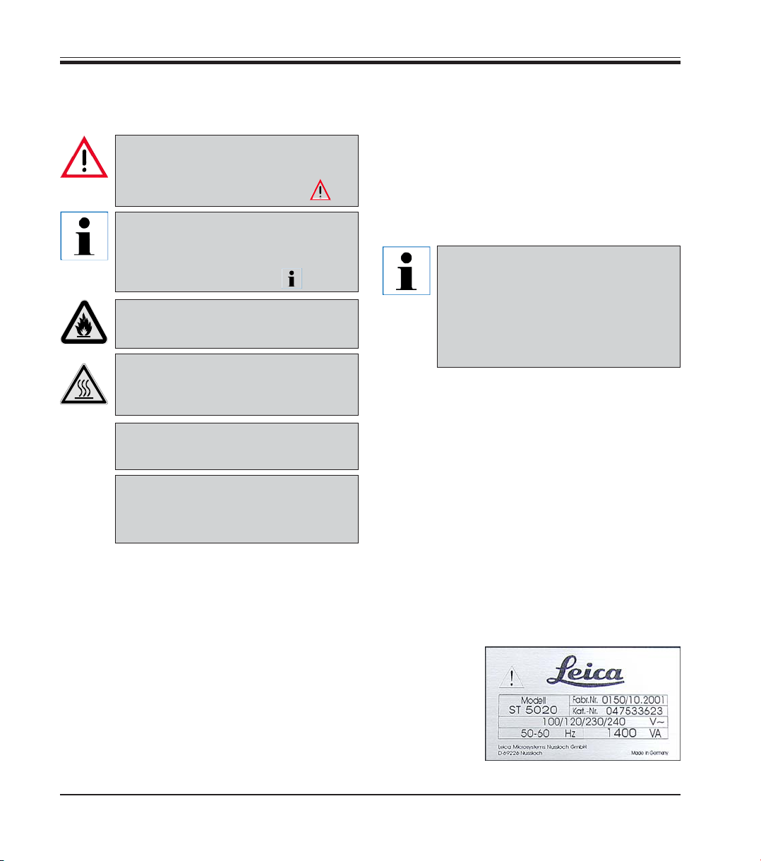
1.4 Instrument type
All information provided in this manual applies
only to the instrument type indicated on the title
page.
A name plate
indicating the
instrument serial number is
attached to the
back of the instrument.
Instructions for Use, V1.9, RevD - 12/2012
Page 7
Make sure to comply with the safety instructions and warnings in this chapter.
Make sure to read these instructions, even if you are already familiar with the operation
and use of other Leica products.
2.1 Safety instructions
2. Safety
This Instructions for Use includes important information related to the operating safety and
maintenance of the instrument and it is an important part of the product.
If additional requirements on accident prevention and environmental
protection exist in the country of operation, this Instructions for Use must
be supplemented by appropriate instructions to ensure compliance with
such requirements.
Material safety data sheets can be obtained from the supplier of the chemicals.
They are also available on the Internet:
http://www.msdsonline.com
The protective devices on both instrument and accessories may neither be removed nor
modified. Only authorized and qualified service personnel may repair the instrument and
access the instrument’s internal components.
This instrument has been built and tested in accordance with the following safety regulations
on electrical measuring, control, regulating and
laboratory devices.
In order to maintain this condition and to ensure
safe operation, the operator must observe the
instructions and warnings contained in this Instructions for Use.
For current information about
applicable standards, please refer
to the CE declaration of conformity
on our Internet site:
www.LeicaBiosystems.com
2.2 Warnings
The safety devices installed in this instrument by the manufacturer only constitute the basis for
accident prevention. Primarily responsible for accident-free operation is above all the institution which owns the instrument and, in addition, the designated personnel who operates, services or repairs the instrument.
To ensure trouble-free operation of the instrument, make sure to comply with the following instructions and warnings.
Leica ST5020
7
Page 8

2. Safety
Warnings - Markings on the instrument itself
Markings on the instrument showing the warning triangle indicate that the correct
Instructions for Use (as defined in this manual) must be followed when operating or replacing the item marked.
Failure to adhere to these instructions may result in an accident, personal injury, damage
to the instrument or accessory equipment.
Some instrument surfaces, which become hot during operation are marked with
this warning label. Touching these surfaces may cause burns.
Warnings - Transport and Installation
The instrument may only be transported in an upright position.
Four people are needed to lift / carry the instrument.
Install the instrument on an even laboratory bench which must be absolutely level.
Do not expose the instrument to direct sunlight (windows).
The instrument MUST be connected to an earthed mains power outlet socket. The instrument must not be connected to an extension cord without protective earth conductor.
The instrument will automatically adjust to the required voltage and frequency at the
place of installation.
If new ovens are installed, they must be adjusted to the voltage and frequency required at
the installation site.
The instrument must be set up in a well ventilated area, free from any ignition sources.
The chemicals to be used in the Leica ST5020 are both flammable and noxious. Do not operate the instrument in rooms with explosion hazard.
If there is a significant difference in temperature between the warehousing and the installation site of the instrument and if at the same time there is a high air humidity level,
condensation water may form. In this case, a waiting period of at least two hours must be
observed before the instrument is switched on. Failure to adhere to this waiting period
may result in damage to the instrument.
Warnings -handling reagents
Be careful when handling solvents!
Always wear rubber gloves and safety goggles when handling the chemicals used in this
instrument.
Reagents used for tissue infiltration can be both toxic and/or flammable.
Dispose of waste solvents with care according to local regulations and the waste management policy of the company or institution.
8
Instructions for Use, V1.9, RevD - 12/2012
Page 9
Warnings - Operating the instrument
The Leica ST5020 may only be operated by trained laboratory personnel, according to its
designated use and per the present Instructions for Use.
In case of emergency switch off mains and unplug the power chord.
While working with reagents (filling / emptying the reagent stations, working on the instrument while the lid/s is/are open) appropriate protective gear (lab coat, gloves, safety
goggles) must be worn.
Make sure to operate the instrument either with the activated carbon filter or with the exhaust air hose. Even when the instrument is operated according to its designated use,
hazardous solvent fumes develop, which are damaging to the operator’s health and do
also pose a risk of fire!
Risk of fire, when working with an open flame (Bunsen burner) immediately next to the
instrument (solvent fumes)! - Therefore, keep a safety distance of 2 meters!
If a staining program is to be interrupted for an extended period of time, do not leave any
slide racks in the tap water stations, in order to prevent them from drying out.
Warnings - Cleaning and maintenance
Prior to each maintenance and/or cleaning, switch the instrument off and disconnect
mains power. Do not clean the instrument with solvents containing acetone or xylene. No
liquid may be spilled into the internal components of the instrument - neither during operation nor during cleaning.
When working with cleaning detergents, comply with all safety instructions by the manufacturer of the product and the laboratory management policy.
Wash the tap water and reagent stations in the dishwasher at a temperature of max.
+65°C (149 °F). Use a standard detergent for laboratory dishwashers.
At any rate avoid washing the stations at higher temperatures, as the stations may become deformed!
Spilled solvents (reagents) have to be wiped away immediately! - In case of long-term exposure, the lid surfaces are only conditionally resistant to solvents!
To clean the lids, control panel and housing, use mild household detergents; - see safety
instruction above for non-appropriate ingredients!
Caution with sequences which involve an oven at the initial step.
In this case the loading unit, out of which the specimen holder is removed via the
transport arm, must NOT be filled with an inflammable reagent (e.g. xylene).
As the oven temperature is up to 80°C (176 °F), the reagent may ignite and cause damage
to the device and to the samples.
For the same reason, steps conducted INSIDE an oven must never be carried out from a
reagent station with inflammable reagents.
2. Safety
Leica ST5020
9
Page 10
3. Instrument components and specifications
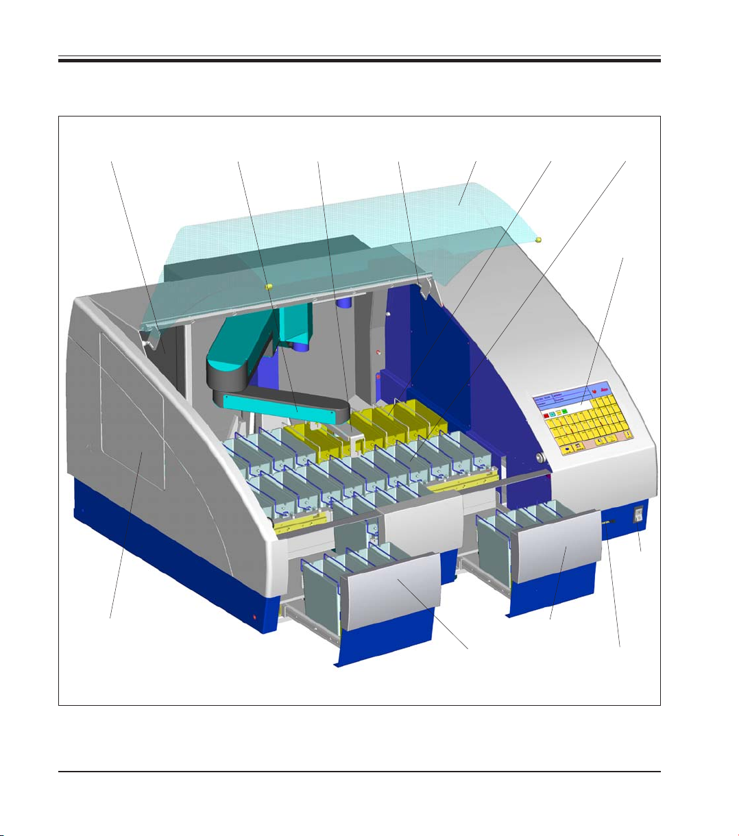
3.1 Overview - Instrument components
Activated
carbon filter
Single (Double)
Transfer arm Lid
carrier
Oven
modules
Wash
stations
Reagent
container
Color touch
screen
Transfer to
Coverslipper
Leica CV5030
10
(optional)
Mains
switch
Load
drawer
Exit
drawer
Slot for
PCMCIA
card
Fig. 1
Instructions for Use, V1.9, RevD - 12/2012
Page 11
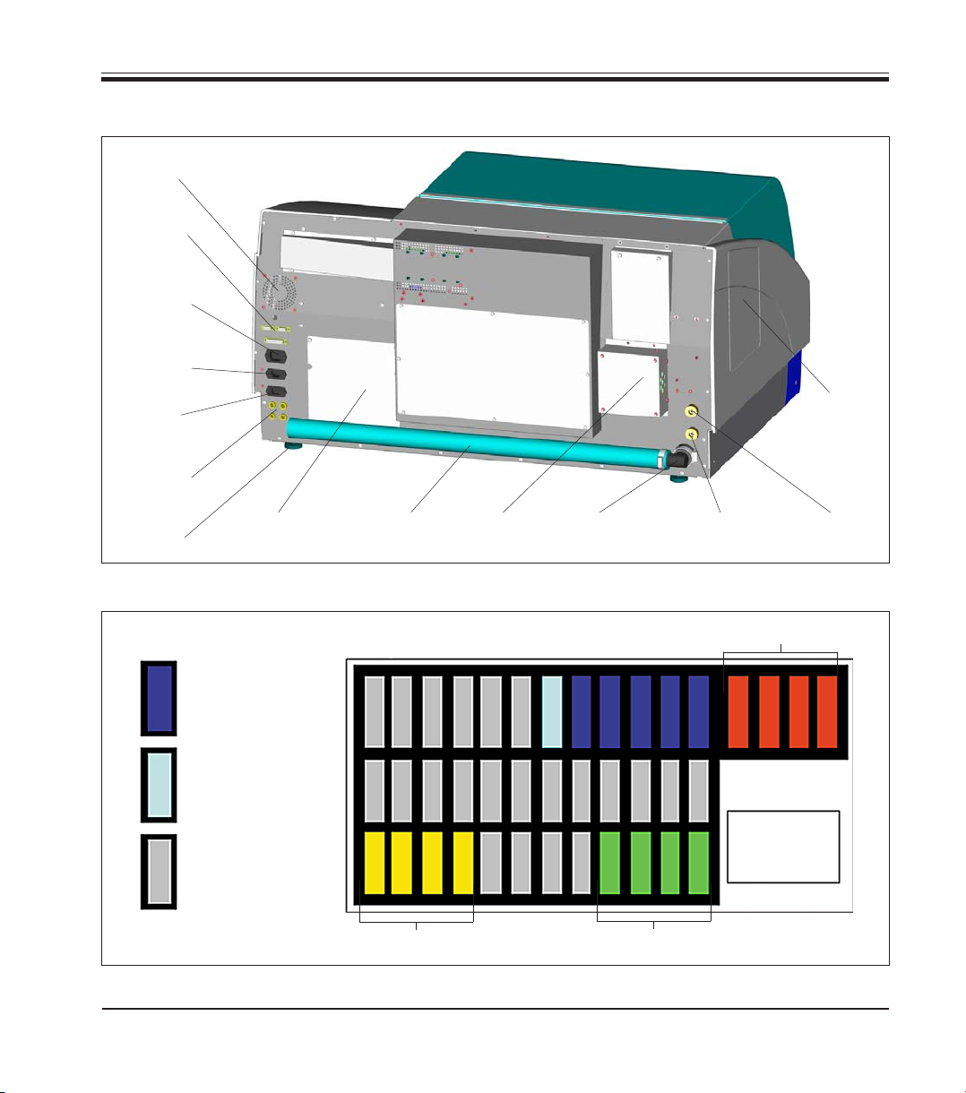
Rear of instrument
Fan
electronic
Data
connections
Power supply
inlet
(electronic)
Power supply
outlet
3. Instrument components and specifications
Mains
Power supply
inlet
Secondary
fuses
adjustable
foot
Container map
Wash
stations
Wash
station
DI-water
Reagent
container
Cover for
Oven-Modules
Transfer to
Coverslipper
(optional)
Drain
hose
12 3 456 7 89101112 37383940
25
Exhaust
air duct
181716151413 2322212019 24
29282726 33323130 363534
Drain
outlet
DI-Water inlet
Station 7
Oven-Modules
Color touch
Water inlet
Stations 8-12
screen
Fig. 2
Leica ST5020
Exit drawer
Load drawer
Fig. 3
11
Page 12
3. Instrument components and specifications
3.2 Instrument specifications
• High specimen throughput (at maximum 12 racks simultaneously)
• Simultaneously processing of multiple different programs
• Color TFT-Touch screen
• Graphical and intelligent user Interface
• Context-sensitive On-line Help
• Graphical process representation on color screen.
• Reagent Management System.
• Multilingual.
• Maximum of 40 stations.
• Load drawer with max. 4 stations.
• Exit drawer with max. 4 stations.
• Maximum of 6 wash stations, 2 different water sources possible.
(individually valve-controlled)
TM
• CodeRack
• Overflow Protector (sensor) in stainless steel sink.
• Integrated fume control system with external hose/filter.
Programmable Slide Rack for automatic rack start.
Optional Accessories
• Oven modules max. +65°C and up to 4 stations.
• Heated reagent stations (35 - 70°C max.), max. 2,
• Special Stain Kit.
(modified container with reduced reagent volume and racks).
• System upgrade for Coverslipper integration.
(automated staining and coverslipping without operator interaction).
• Air evacuation hose.
• Slide rack (plastic).
• Adapter for racks from other manufacturers.
To prevent damages to the instrument and specimens, only those accessories and
spare parts which have been authorized by Leica may be installed or used with the
instrument.
12
Instructions for Use, V1.9, RevD - 12/2012
Page 13

3. Instrument components and specifications
3.3 Standard delivery - packing list
The Leica ST5020 standard delivery consists of the following items:
1 Leica ST5020 basic instrument
31 Reagent vessels, assy. (with handles and lids) 14 0475 33659
5 Wash vessels, assy. 14 0475 33660
2 Activated carbon filter 14 0474 32273
1 Set of power cords:
1 Power cord "D" 14 0411 13558
1 Power cord "UK" ST-BU F-5A 14 0411 27822
1 Power cord "USA-C-J" 14 0411 13559
1 Accessory-Kit consisting off: 14 0475 39617
1 Jumper cable - mains 14 0411 34604
3 Reagent vessels, assy. (with handles and lids) 14 0475 33659
1 Set of clips, red, pack of 5 14 0475 33637
1 Set of clips, yellow, pack of 5 14 0475 33633
1 Set of clips, white, pack of 5 14 0475 33632
1 Set of clips, light blue, pack of 5 14 0475 33634
1 Set of slide racks 30, plastic, pack of 5 14 0475 33750
1 Waste water hose, 4 m length 14 0475 35748
1 Hose clamp for waste water hose 14 0422 31972
1 Tap water inlet hose, 2,50 m length, assy. with 3/4” connection for water tap 14 0475 32325
1 ‘V’ strainer 3/4”-40/22 A6 (strainer for inlet hose) 14 0456 36101
1 Threaded nippel 14 0474 33063
2 Gaskets for tap water inlet hose 14 0300 00132
1 Box level 14 0475 37629
1 Special O-ring grease for valves and O-rings (OHA), 25 ml 14 0336 36657
1 PCMCIA Flash Card, with adapter 14 0475 42526
1 Tool set:
1 Screw driver 5.5 x 200 14 0170 10702
1 Allen key, size 3.0, with handle 14 0194 04764
1 Allen key, size 4.0, with handle 14 0194 04782
1 Allen key, size 6.0 14 0194 03959
1 Ring-head wrench, size 13 14 0330 37628
1 Single-head wrench, size 17 14 0330 19641
1 Set of replacement fuses:
4 x T 2.0 A 14 6943 02001
2 x T 2.5 A 14 6943 02501
2 x T 4.0 A 14 6943 04001
1 Instructions for Use Leica ST5020 Multistainer 14 0475 80101
Leica ST5020
13
Page 14

3. Instrument components and specifications
3.4 Technical Data
General
Approvals: The instrument-specific marks are located next to
the identification label
Nominal voltage: 100 V - 120 V +/- 10%
230 V - 240 V +/- 10%
Nominal frequency: 50 to 60 Hz
Maximum power draw: 1400 VA
IEC 1010 classifications: Protective class 1
Pollution degree 2
Overvoltage installation category II:
• 800 V impulse (120 V systems)
• 1500 V impulse (240 V systems)
Remote alarm relay: 24 V AC/DC, maximum 2 A
Connection:
potential-free contact
(can be operated both as normally open and as
normally closed circuit)
Primary fuses: Fa. Schurter: type FST, mains power inlet 2 x T 8 A
Secondary fuses: Melting fuse, Ø 6.3x32 mm
Type: Schurter FST
F1: T 2.0 A
F2: T 2.0 A
F3: T 2.5 A
F4: T 4.0 A
Operating temperature range: 15 °C to 40 °C
Relative humidity: 10% to 80%, non-condensing
14
Instructions for Use, V1.9, RevD - 12/2012
Page 15

3. Instrument components and specifications
Dimensions and weight
Basic instrument (W x D x H), in mm: 1060 x 750 x 540
Dry weight, unpacked: ca. 90 kg
Weight, packed: ca. 110 kg
Capacity data
Specimen slide throughput: depending on the program-structure
Loading capacity: max.12 slide racks (with 12 different Programs)
Slide rack capacity: 30 specimen slides
Total number of stations: 40 (36 + 4 Oven)
Total number of reagent stations: max. 34
Reagent container volume: 450 ml
Number of wash stations: max. 5 and 1 DI-water (optional)
Oven (optional): 2 or 4
Oven chamber temperature: 40 °C to 70 °C or 104 °F to 158 °F
Incubation time setting: 0 sec. up to 23 hours, 59 min., 59 sec.
Load/unload stations: max. each 4, min. each 1
Permanent memory capacity: max. 50 Programs, up to 40 program steps each
Integration: connection to Leica CV5030 Coverslipper (optional)
Leica ST5020
15
Page 16
3. Instrument components and specifications
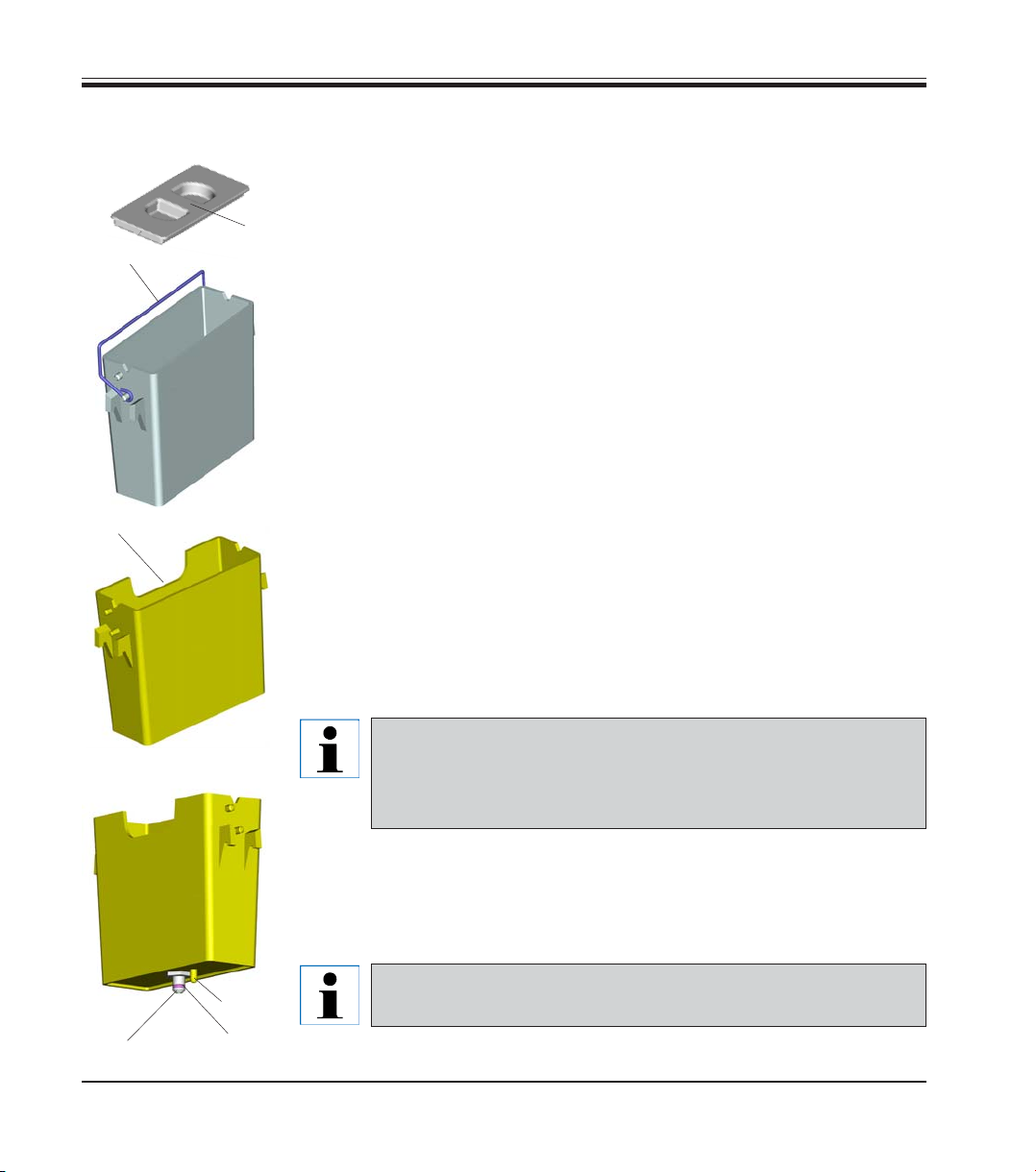
3.5 Container system
Reagent container
The Reagent containers can be individually removed for filling.
For use, fill the reagent containers to the line marked on the inside
6
(approx. 450 ml capacity) and place into position in the instrument consis-
1
3
tent with the programs you wish to run.
Ensure that the reagent containers are correctly seated and that the
handles (1) are over to the side and will not obstruct slide rack movement.
Lids (6) are provided to reduce evaporation while the reagent containers
are not in use.
The Load and Exit drawer containers (E25 and L36) can be filled with a reagent if desired.
However, the instrument will not control the immersion time in these stations.
Wash stations
The wash system consists of five (optional six) wash stations each capable of holding one slide rack. Water enters the wash station through a
connection piece (2) in the base and exits from the overflow lip (3) at the
top left hand edge.
16
Wash stations have a locating pin (4) and can only be inserted
one way. Take care when fitting or removing wash stations as
excessive force may damage the O-ring (5) used as a seal.
Lubricate the O-ring seal before fitting a wash station.
To use the wash system, slowly turn the laboratory tap on fully. The flow
control valve in the Leica ST5020 will limit the total water flow in the wash
stations to 1.6 liters/minute/station.
If the water flow drops below this level for any reason the
4
2
5
Fig. 4
wash period specified in the program may have to be extended.
Instructions for Use, V1.9, RevD - 12/2012
Page 17

4.1 Installation site requirements
4. Setting up the instrument
• Stable, exactly horizontal laboratory bench
with even surface of a minimum width of 1.60
m and minimum depth of 0.80 m.
• Tap water supply located a maximum of 2.50
m and waste water drain pipe a maximum of
2.00 m away from the corresponding in-/outlets at the rear panel of the instrument.
• If the instrument is to be operated with air
evacuation hose, a fume cupboard at a distance of maximum 3.50 m from the instrument is required.
Alternative: operation with activated carbon
filter.
• Sufficient space (ca. 0.90 m) above the laboratory bench for opening / closing the instrument lid without any problem.
4.2 Installing the instrument
• Virtually vibration-free floor.
• Stable ambient temperature between +10 °C
and +40 °C.
• Relative air humidity of maximum 80%, noncondensing.
• Do not place near instruments which might
be sources of vibration.
The chemicals to be used in the
Leica ST5020 are both flammable
and noxious. The instrument must
be set up in a well ventilated area,
free from any ignition sources.
Do not operate the instrument in
rooms with explosion hazard.
• To lift, grip the instrument by the carrying
handles (1, Fig. 5).
Leica ST5020
Four people are required to lift and/
or carry the instrument, as the instrument weighs a total of approx.
95 kg.
• Place the instrument onto the bench.
• Unscrew the carrying handles (remove
1
2
screws (2) with Allen key, size 6.0) and store
away.
• Pull off plastic cover.
Fig. 5
• Check whether all accessories have been
delivered as per your order.
17
Page 18
4. Setting up the instrument
4.3 Tap water supply connection
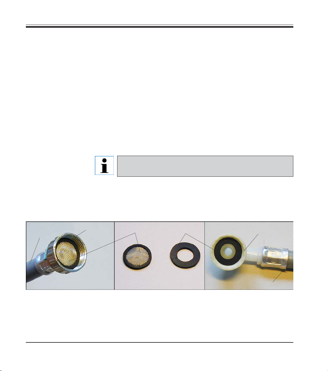
Water filter
In addition to the filter sieve supplied (item 3 in
installing a sediment filter between the water extraction outlet and
ST5020, to guarantee that the instrument is only operated with clean water.
This sediment filter should have the following properties:
Filter fineness: 25 μm
Rate of flow: approx. 10 l/min (with 5 wash stations)
Pressure constancy: 10 bar
Connection to the filter output: 1/2“ external thread
Connecting the tap water inlet hose
• Unpack the tap water inlet hose - mind the two gaskets (4).
7
5
Fig. 6) Leica recommends
This filter insert must be checked and cleaned regularly.
If the filter insert is very dirty it must be replaced.
3
4
6
Fig. 6
18
7
• Insert one gasket (4) into threaded fitting (6). Store away the remaining
gasket(s).
• Insert strainer (3) into union nut (5) (see
Fig. 6) which is screwed onto
the water tap. Do not insert any further gaskets, as the strainer acts
also as a seal.
Instructions for Use, V1.9, RevD - 12/2012
Page 19
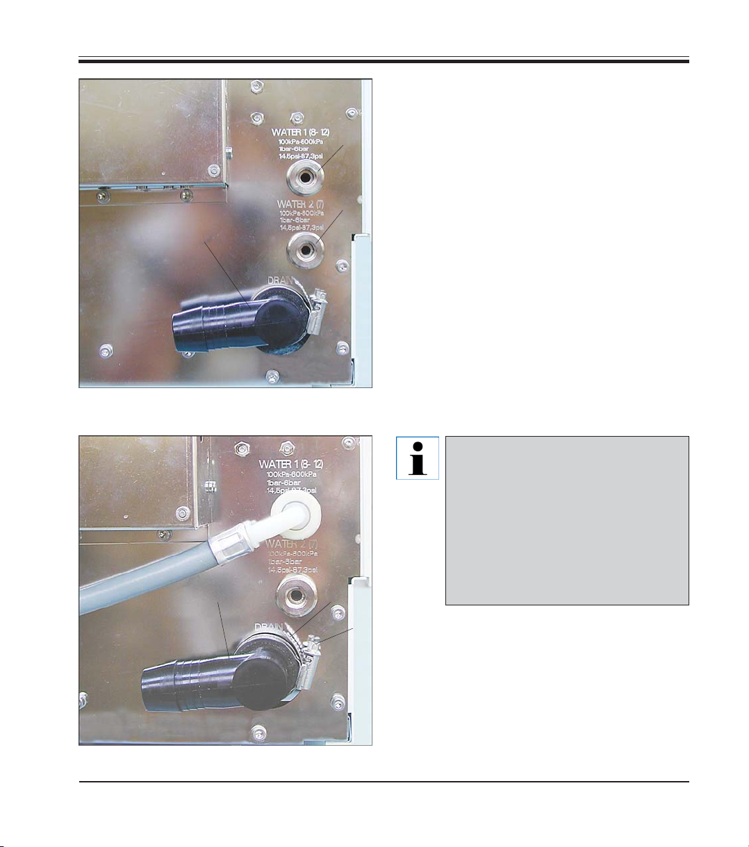
Instrument rear panel
- tap water inlets
10
9
4. Setting up the instrument
• Screw tap water inlet hose (7 in Fig. 8) for
tap water stations 8 - 12 onto water tap and
insert the other end into inlet (8 in Fig. 7) .
8
• If station no. 7 (Fig. 3) will also be used as a
tap water station, connect a second tap
water inlet hose (optional accessory) to inlet
(9).
Fig. 7
Instrument rear panel
water in-/outlets
7
Leica ST5020
10
12
Inlet (9) only provides water (or any
other medium supplied via a separate connection) to station no. 7. To
use station 7 as a water station, a
wash vessel must be inserted and
station 7 must be defined as a ‘tap
water’ or ‘fully-de-ionized water’
station (DI water station) in ‘stations
options’. (see also Chapter 5.5.3)
11
Fig. 8
19
Page 20
4. Setting up the instrument
7
13
15
14
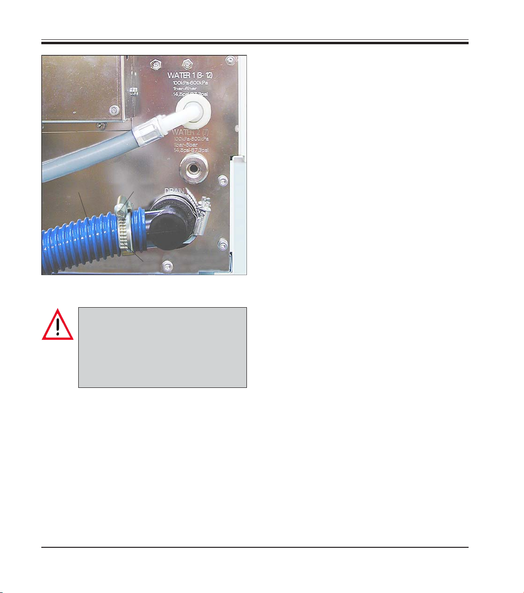
Connecting the waste water hose
• Outlet connection piece (10) can be turned
to point into different directions, depending
on whether the drain water pipe is located to
the left or to the right of the instrument.
• To adjust the connection piece, loosen
screw (11) of hose clamp (12) sufficiently so
that the connection piece (10) can be turned.
Adjust the connection piece as desired (always with the opening pointing slightly
downwards) and retighten screw (11).
• Turn screw (15) to the left (use screwdriver)
until hose clamp (14) opens wide enough to
be slid over waste water hose (13).
20
Fig. 9
Important!
When installing the drain hose always make sure there is a sufficient
descending gradient from the outlet
(connection piece (10)) on the instrument to the drain pipe!
• Fit waste water hose (13) onto outlet connection piece (10) and position hose clamp
(14) as shown in
Fig. 9.
• Turn screw (15) to the right until hose (13) is
secured tightly on connection piece (10) by
hose clamp (12).
• Insert waste water hose (13) into drain pipe
and secure in position.
Instructions for Use, V1.9, RevD - 12/2012
Page 21

4. Setting up the instrument
4.4 Installing the oven (optional)
15
16
Voltage setting
100 - 120 V
23
Voltage setting
230 - 240 V
Rear panel - oven
24
19
21
25
Fig. 11
• Take the oven kit out of the box and verify
whether it is complete.
The following parts must be included:
20
15 - Oven module
16 - Paraffin collecting tray
18
22
17 - Cover
18 - Screws
19 - Washers
20 - Screwdriver
21 - Allen key, size 2.5
22 - Allen key, size 4.0
17
Insert paraffin collecting tray
into corresponding opening in
oven module (possible only in
one direction, as shown here).
Fig. 10
• Check the voltage selector setting and ad-
just if necessary.
Important!
The voltage selector switch must be
set to the same mains voltage as the
instrument.
To adjust the voltage selector setting, insert
screw driver (20) into gap (23) and turn carefully until the white point above the correct
voltage indication is located underneath the
white triangle.
115 means: Instrument voltage 100 -120 V.
230 means: Instrument voltage 230 - 240 V.
Leica ST5020
21
Page 22

4. Setting up the instrument
27
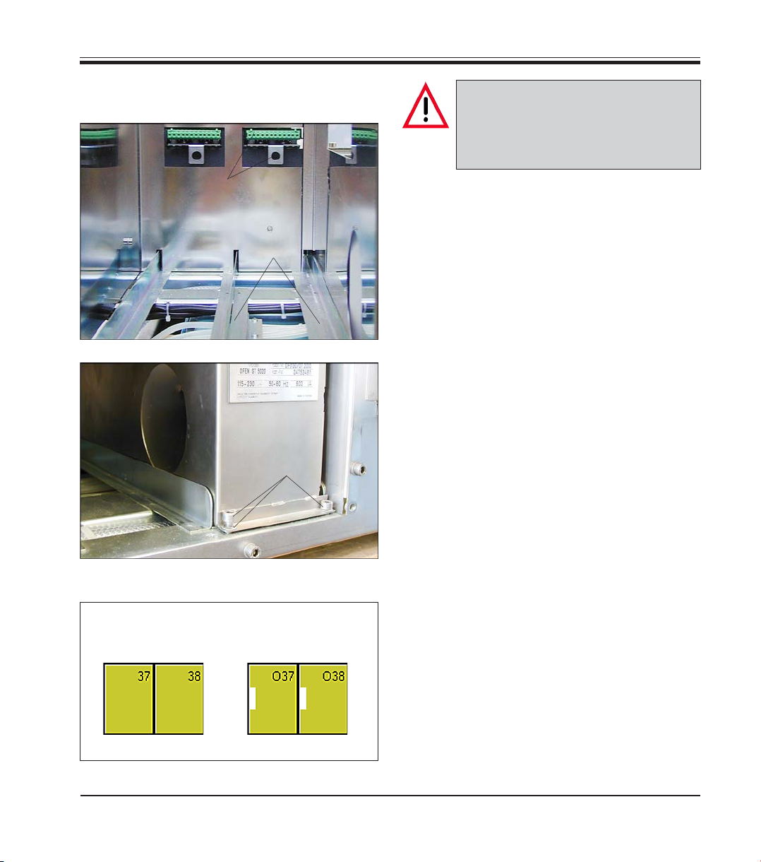
Important!
Prior to taking any further installation steps, switch the instrument off
and unplug from mains.
29
28
26
29
30
• Cover panel (26) must be removed from the
right inner wall of the instrument, so that the
transfer arm can access the oven stations.
27
• To do so, remove six screws (27) (Allen key,
size 2.5) and remove cover panel (26).
• Store screws and cover panel in safe place
for further use.
Fig. 12
• Remove cover panel (28) located to the right
of the electrical connections at the rear wall
of the instrument.
• To remove panel (28), only remove screws
(29).
Do not loosen the two screws (30)!
22
29
29
Fig. 13
• Once the oven is installed, attach cover
panel (part of oven kit delivery) (17
in Fig. 10)
with four screws (29) in such a way that the
voltage selected is visible from the outside.
Instructions for Use, V1.9, RevD - 12/2012
Page 23
4. Setting up the instrument
Installing the oven
(continued)
31
15
32
18, 19
Fig. 14
Important!
If only one oven is installed, it must
be located on the right side (seen
from the rear of the instrument).
• Place oven on rails (32) and insert.
• Keep pushing until the connection pieces of
the oven (positioning pin (24), connector
strip (25), see
Fig. 11) lock into the corre-
sponding connections (31) in the instrument.
• Next, use the two screws (18) and washers
(19) to secure the oven (15) in the bores provided in the instrument for that purpose.
• If a second oven has been ordered, install it
the same way as the first.
Indication prior to
installing the ovens
Leica ST5020
INSTRUMENT STATUS
Indication with
ovens installed
Fig. 15
Fig. 16
• Fasten cover (item 17, Fig. 10) so that the
voltage range selected for the oven (15) is
the same as the engraved voltage range.
• Plug the instrument back into mains and
switch on. The oven modules are detected
automatically and are displayed accordingly
in ‘instrument status’.
• Go to ‘stations options’ and set the desired
oven temperature.
(See
chapter 5.5.3, page 56 for further de-
tails).
23
Page 24

4. Setting up the instrument
4.5 Connecting the air evacuation hose (optional)
64
65
63
62
61
66
68
63
60
Fig. 17
If the instrument is operated without activated
carbon filter, the air evacuation hose must be
installed instead.
The air evacuation hose is attached to fan housing (68) located at the rear left of the instrument. Unpack the components supplied and
check for completeness. The package must
contain the following items:
60 - Screw driver
61 - Allen key, size 2.5
62 - Hose clamp
63 - Allen screw with washer
64 - Hose connection piece with seal
65 - Air evacuation hose
65
64
67
62
66
• Fasten connection piece (64) with two
screws (63) into tap holes (66) in fan housing
(68).
• Turn clamping screw (67) to the left (use
screw driver (60) until hose clamp (62) is
loosened far enough so that it can be slipped
over the air evacuation hose.
24
Fig. 18
• Place air evacuation hose (65) together with
hose clamp (62) onto connection piece (64)
(see Fig. 18, right).
• Tighten screw (67) of hose clamp (62) (turn
to the right) to secure the hose.
Instructions for Use, V1.9, RevD - 12/2012
Page 25

4.6 Inserting the activated carbon filter
51
33
4. Setting up the instrument
Important for trouble-free
operation:
34
The sealing profiles (33) must
fit against the rear wall of the
filter housing (34).
Filter - inserted
Fig. 18
Make sure to insert the filter
with the correct side pointing
upwards: the three arrows on
the label (51) located at the
right of the filter must point to
front.
4.7 Leveling the instrument
• Once all accessories are installed (don’t forget the rear panel!), move
the instrument to its final position.
• Prior to leveling the instrument, check whether the bench surface of
the laboratory bench where the instrument will be installed is flat and
exactly horizontal.
• Otherwise, use the box level (standard delivery) to determine the highest point of the bench. Next, the instrument foot located at the highest
point of the bench must be screwed in almost completely (
- Then level the instrument adjusting each foot as needed.
Fig. 19
35
Once the activated carbon filter is inserted, push lever (35)
downwards to properly secure the filter in the filter
housing.
see Fig. 21).
Leica ST5020
25
Page 26
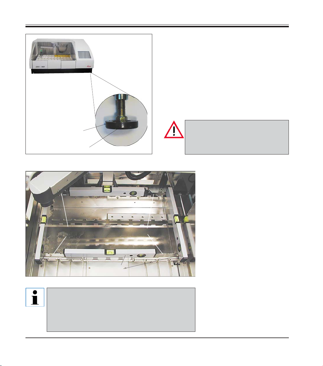
4. Setting up the instrument
instrument feet
Bring the instrument to
an exact horizontal position by screwing the adjustable feet in / out as
needed.
Adjustable
To do so, proceed as follows:
• Remove all vessels located in stations 1 - 24
so that the vessel holder frames can be used
to support the box level for measuring purposes.
• All four instrument feet (37) are height-adjustable.
To adjust, place single head wrench, size 13
(standard delivery) onto hexagon bolt (36)
and adjust each foot as needed.
36
37
Fig. 21
B
C
39
39
D
38
Abb. 22 shows all four points (A to D) where the box
level must be positioned for leveling the instrument.
For leveling, the box level must be placed onto vessel holder frame (39). - Do not place the box level
elsewhere.
Make sure, all four instrument feet
are firmly set on the bench surface
once the instrument adjustment has
been completed.
• For leveling, position box
level (38) alternately in positions (A and B) - see Fig. 22
on the vessel holder frame.
• Screw the instrument feet inward / outward as needed,
A
gradually bringing the instrument into a horizontal position. Start with the instrument
foot located opposite the
highest point of the laboratory bench.
Fig. 22
• Finally, place the box level in
positions (C und D) to doublecheck whether the instrument is in fact in a horizontal
position.
26
Instructions for Use, V1.9, RevD - 12/2012
Page 27
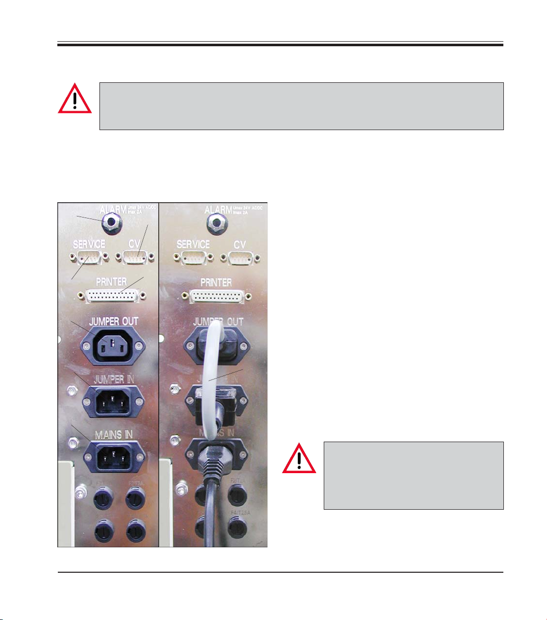
4.8 Electrical connection
The instrument MUST be connected to an earthed mains power outlet socket.
The instrument is supplied with a set of country-specific power cords.
Make sure to use the appropriate mains cable for the local voltage supply (wall outlet).
Sockets for mains power
supply and data transfer.
Secondary fuses.
50
48
44
45
42
Jumper cable / power cord
connected correctly
for mains power supply
49
47
43
4. Setting up the instrument
All electrical connections are located at the rear
of the instrument to the left (Fig. 23).
Power supply
• Connect mains cable to mains power supply
socket (42).
• Jumper cable (43) connects the mains power
supply output (44) to the electronics module
input (45).
Data connections
• Printer port (47)
A suitable printer (and cable) can be recom-
mended by your Leica distributor. If conformance to electromagnetic interference standards is essential, a specially shielded printer
cable will be required.
• Serial port (48)
Access for technical service.
• Connection for Leica CV 5030 Cover slipper
(49).
Leica ST5020
46
Fig. 23
All interfaces may be used only with
devices that have been tested in accordance with EN 60950 and which
satisfy the requirements for SELV circuits.
Other connections
• Socket for remote alarm system (50)
• Secondary fuses (46)
27
Page 28

4. Setting up the instrument
4.9 Alarm functions
Instrument alarm
The instrument alarm is generated from within
the Leica ST5020.
The instrument alarm is used for all alarm situations.
Remote alarm
This alarm is external to the Leica ST 5020.
Any alarm generated in the instrument, no matter of which alarm type, is passed on to the remote alarm system, even when the type 1 instrument alarm is switched off.
The remote alarm sound/volume is the same for
all alarm types - individual sound and volume
settings selected in the ALARM menu (see
chapter 5.4.2) are disregarded.
4.10 Transport
The following measures must be taken if the instrument is to be transported:
• Remove all the racks.
• Empty all reagent containers.
• Secure the transport arm of the instrument.
• Disconnect the instrument from the supply
voltage.
• Detach the water inlet hose and the water
drain hose.
• If necessary, detach the air evacuation
hose.
• Reattach the carrying handles (see
4.2).
• If the instrument is transported over longer
distances, pack the instrument in its original
shipping box and follow the measures for
securing it for transport.
Chapter
Connecting a remote alarm device
The remote alarm system which can be optionally connected works with a potential-free relay. If an alarm is generated, the alarm circuit
closes.
The remote alarm device connected to the instrument must be rated at less than 2 amp. A
maximum voltage of 24 V AC/DC may be present.
The remote alarm device is connected to the
printer via a 6.3 mm-diameter jack connector
(optional accessory).
For details on how to connect a remote alarm
device to the Leica IP, please contact your local
Leica sales office or the manufacturer Leica
Microsystems Nussloch GmbH directly.
Securing the transport arm:
• Change to the Supervisor mode.
• Call up the keyboard (e.g. as required for entering the password, see
• Enter the command “#transport“.
The arm moves down into station 6 where it remains and can no longer be moved.
After switching the instrument off, it is ready for
transport.
Chapter 5.4.3)
28
Instructions for Use, V1.9, RevD - 12/2012
Page 29

5.1 Switching the instrument on
Caution!
The instrument MUST be connected to an earthed mains power outlet socket.
It is recommended that the Leica ST5020 be plugged into a wall socket that has Ground
Fault Circuit Interruption (GFCI) protection - as an additional electrical safeguard.
• Before you connect the instrument to the wall socket, make sure the
mains switch at the bottom right of the instrument is in position OFF (‘0’).
• Connect the mains cable to the wall socket and switch on the mains
supply at the wall socket (if applicable).
• Switch the mains switch ON (‘I’).
5. Operation
• When switched on, the instrument will take a
few seconds to initialize. During initialization
the screen is blue, initialization progress is
indicated by a line of white dots.
• After approx. 30 seconds, the graphic surface will become visible. The working area is
still black. A row of “X“ displays the software loading in the information line.
• Next, the LANGUAGE CHOICE menu (
Fig. 24)
will be shown on the screen for approx.
three secs.
Fig.8
• If you select a different language (press the
corresponding button), the MAIN MENU
(Fig. 32, chapter 5.3.4) will be shown next, in
the new language selected.
• If no changes are made, the INSTRUMENT
STATUS menu (
Fig. 25) will open up.
INSTRUMENT STATUS is the standard
screen - all functional descriptions in the
present
chapter 5 start from INSTRUMENT
STATUS.
Leica ST5020
Fig. 24
Fig. 25
29
Page 30

5. Operation
5.2 Setup checklist
Once the instrument is ready to be switched on, all menus listed below must be accessed
and the necessary parameters be properly selected. The Supervisor mode must be active
to have access to all menus. For detailed advice on how to select individual parameters,
refer to the on-line help feature.
Screen →
→
→
→→
→→
→
←
→
Press button
↓
↓
Parameter settings
Select a language - either when switching the instrument on or in the LANGUAGE CHOICE menu.
In USER INTERFACE, set parameters as required.
Verify whether DATE and TIME are correctly set.
Open the REAGENT LIST menu, check the settings
and complete, if necessary.
In INSTRUMENT STATUS, select a STATION TYPE
for each station.
Allocate the correct reagent to each STATION.
Reagents can be allocated either when creating the
programs or in the STATION DETAILS menu.
Be sure to fill the reagent containers with the correct reagents (as allocated)!
Create the PROGRAMS needed.
Existing programs can be copied and modified.
30
→→
→→
→→
In MOVE, select the number of dips and the speed of
the transfer arm.
Allocate a CLIP COLOR to each clip.
Select time, quantity and paper format of the daily
printouts.
Instructions for Use, V1.9, RevD - 12/2012
Page 31

5.3 Touch screen functions
5.3.1 User interface - overview
The Leica ST5020 Multistainer is programmed and
operated via a colored TFT- touch screen.
Basic screen layout
Only those control elements that can actually be accessed by the user are displayed on the screen.
The number of accessible control elements depends
on the access level selected.
Current
date
Current
time
Instrument
name
Menu
currently
selected
Information
line
Access level
selected
5. Operation
The screen is
horizontally
divided into
three functional areas:
↓↓
↓
↓↓
Status bar
Up one
menu level
Leica ST5020
Area for buttons
displayed depen-
ding on current
menu
Up one level
to main
menu
Switching from
user to supervisor
access level and
back
Operation
Button bar
Fig. 26
On-line help
on current
menu
31
Page 32

5. Operation
Button symbols
Enabled
Disabled
The six buttons described below have the same function in all menus.
On the left side of the button bar (
Fig. 26) there will either be the button
BACK → To go back to the previous menu.
or the two buttons
CONFIRM → To exit the current menu (new entries will be
stored upon exiting).
CANCEL → To exit the current menu without storing any
of the modifications made.
PRINT → Displayed in menus containing tables and lists.
If pressed, the list selected will be printed
immediately. Immediate printing does not affect the
daily printout of all protocols (
MENU → To go back to the main menu (
see chapter 5.4.6).
see chapter 5.3.4)
HELP → The on-line HELP feature can be accessed from
any screen. HELP provides context-sensitive
explanations, i.e. help topics displayed will vary
depending on the menu HELP is accessed from.
Some button symbols may look differently depending on whether they
have been enabled or disabled.
Disabled button symbols appear in a lighter color than enabled ones.
They are only shown to complement the menu being displayed, in order to avoid mix-ups and to remind the user that the corresponding
function has been disabled. They can, however, not be accessed.
32
→
There are several functions where the user can choose from a number
of given parameters.
If there are only two parameters available, the parameter currently enabled is shown on the button. Pressing the button switches to the alternative parameter.
If there is a choice of more than two parameters, the range of available
parameters is shown on the button in square brackets.
Each time the button is pressed, the next parameter is accessed, starting again with the first after the last one in the row has been selected.
Instructions for Use, V1.9, RevD - 12/2012
Page 33

Tables/lists
5. Operation
The program contains numerous tables.
The first row of a table contains the headers of
the individual columns.
The rows below contain the actual content.
Selected rows appear in blue color (1).
1
Fig. 27
2
3
Fig. 28
When a tabled is accessed, the blue bar is always located in the first content row.
If a table is empty, no blue bar is displayed.
Headings of column where parameters can be
entered by the user (in supervisor mode) (
Fig.28)
are displayed as buttons (3).
In supervisor mode, some tables also contain a
number of additional buttons (2), depending on
the parameters selectable.
Leica ST5020
The navigation buttons are located at the right border of the screen.
Each table contains two navigation buttons for row-by-row scrolling.
Each time one of the buttons is pressed, the highlighting bar is moved one
row up or down. You can also highlight rows by touching them directly.
For long lists, a set of page-up / page-down buttons will be displayed in
addition.
Pressing on of these buttons moves the highlighting bar one entire page
up or down; the last (first) row of the current page will be the first (last)
row of the new page. If there is no entire page left to the beginning (end)
of the table, the new page will be displayed starting with the first row
(ending with the last row) of the table with the highlighting bar jumping to
the first content row on the page.
Each table contains a PRINT button. If the button is pressed, the current
status will be printed out immediately.
33
Page 34

5. Operation
5.3.2 Data entry
Parameters and data can be set / entered several different ways:
Alphanumeric keyboard
4 5
The maximum number of characters to be entered may not be exceeded.
The following numbers are predefined:
Reagent names: maximum 20 characters
Program names: maximum 20 characters
Program abbreviation: maximum 3 characters
Passwords: minimum 4 characters, maximum 20 characters.
The following buttons have special functions:
If pressed, button remains locked, all letters will be displayed in capitals.
After the first button has been pressed, SHIFT is released and the keyboard will return to small letters.
Fig. 29
The alphanumeric keyboard (Fig.
29) resembles a computer key-
board. An entry field (5) and instructions on what kind of data to
enter (4) are located above the
keyboard. The amount of characters that can be entered varies,
depending on the type of data to
be entered. If there is a predetermined number of characters to
be entered, that number will be
displayed in the entry field. The
cursor is located on the left.
34
If pressed, button remains locked - all letters will be written in capitals.
Press SHIFT LOCK once more to return to small letters.
Press this button to display special characters, above all vowels carrying
accents. These can also be displayed in capitals by pressing SHIFT/SHIFT
LOCK. After a special character has been selected, the keyboard automatically reverts to standard indication.
Instructions for Use, V1.9, RevD - 12/2012
Page 35

Navigation buttons
Numerical keyboard
5. Operation
The navigation buttons have the same function in both keyboard types
(numerical, alphanumeric):
• Cursor jumps to the left / right border of the entry field.
• Cursor is moved one character to the left / right.
• Character on the left of the cursor is deleted.
• Entry field located above the numeric keypad (left
6
Fig. 30
aligned). Instructions on which parameter to be entered (6) are displayed above the entry field. Entry
position is marked by cursor, default parameters will
be stored. Pressing a numerical key deletes default
parameters.
• If a figure entered exceeds or falls short of a limit
setting, that limit setting will be displayed when
CONFIRM in the menu bar is pressed and the entry
field will not be exited.
• Depending on the type of entry to be made, only a
limited number of numeric characters can be entered.
• Press CONFIRM or CANCEL to exit the numerical
keypad.
Leica ST5020
Press CONFIRM to store entries and go back to the previous menu.
Press CANCEL to go back to the previous menu without storing any new
entries.
35
Page 36

5. Operation
5.3.3 Access levels
Administrator symbol
→
User symbol
Fig. 31
The Leica ST5020 may be configured to allow
two level of user access.
User access level
• Users may run programs and view results.
On this level, the USER symbol is displayed
in the upper right corner of the touch screen.
Supervisor access level
• Administrators may perform all user functions, and additionally create programs and
perform the instrument setup functions.
• To access supervisor level, press SUPERVI-
SOR: the keyboard will be displayed. If a
password has been allocated, the keyboard
will appear on the screen.
chapter 5.4.3 for details on password
(See
allocation).
Enter the ‘Admin’ password and confirm.
The SUPERVISOR symbol will then be displayed instead of the USER symbol and the
SUPERVISOR button will be replaced by the
USER button.
36
In SUPERVISOR mode, NO programs
can be run. Switch to USER mode to
start a program.
You can only go back to SUPERVISOR mode (e.g. to select / change
settings) once all running programs
have been finished.
The Leica ST5020 may be configured
so that all functions are accessible
to all staff - effectively the instrument is in Supervisor access level
the whole time. See chapter 5.4
“System setup“.
Instructions for Use, V1.9, RevD - 12/2012
Page 37

5.3.4 The main menu
After switching the instrument on, the main menu will be displayed only if the language is
changed. INSTRUMENT STATUS is actually the standard screen.
In all functional descriptions below, INSTRUMENT STATUS is assumed to be the standard
screen, all buttons shown start from INSTRUMENT STATUS.
↓
5. Operation
Opens up the main menu from where all program functions can be accessed.
The main menu can be accessed directly from almost all functions.
To be able to access
all necessary settings, the instrument
must be operated in
SUPERVISOR mode.
Fig. 32
From the main menu, four subordinate menus can be accessed:
• INSTRUMENT STATUS see chapter 5.5
• STAINING SCHEDULE see chapter 5.7
Leica ST5020
• PROGRAMS see chapter 5.6
• OPTIONS see chapter 5.4
37
Page 38

5. Operation
5.4 System SETUP
In OPTIONS you find all submenus which
• determine what the user interface looks like:
- USER INTERFACE
- CLIP COLOUR
- DATE/TIME
• manage the reagents:
- REAGENT LIST
• control the print functions (optional)
- VIEW/PRINT
All of the settings for the menus STATION OPTIONS, USER INTERFACE, REAGENT LIST and
VIEW/PRINT can be accessed in user mode. All other menus require administrator mode.
Determine speed
and number of
dips
→
• determine the station type and allocate
reagents:
- STATION OPTIONS
• define the dips / transfer speed:
- MOVE
• allow user data to be loaded and backed up
- BACKUP
Set user-defined
system parameters
Set and control
stations
Allocate and
control reagents
Detect color of
unknown clip and
allocate
38
Calibrate screen
Define screen
displays and
printouts
Backup and read in
all user data
Set / control date
and time
Fig. 33
Instructions for Use, V1.9, RevD - 12/2012
Page 39

5. Operation
5.4.1 User interface
→
In this screen you can select:
• BRIGHTNESS OF SCREEN
• TEMPERATURE MEASURING UNIT
• BUTTON CLICK
Two measuring units can be chosen from:
• The parameter selected is displayed on the
button, next to the “=“ sign.
→
←→
Fig. 34
↓
• Press the button to switch to the alternative
measuring unit.
Leica ST5020
Language selection
To select between the two languages that are
available, one of these two languages always
being ‘English’.
The second language (default = German) next to
English is exchangeable.
A PCM-CIA expansion card containing the desired language is needed.
Switch the instrument off and insert the PCMCIA card into the slot next to the mains switch.
Switch the instrument back on, the new language will be automatically loaded.
Fig. 35
39
Page 40

5. Operation
5.4.2 Alarm
→
There are three different types of alarms, each one allocated to certain events. Alarm type
1 can be simply switched off, alarm types 2 and 3 cannot.
Fig. 36
Different sound signals, in several intensity levels, can be allocated to
each alarm type.
→
Alarm type 1:
Alarm 1 is generated when user intervention is
required.
Alarm type 2:
An error has occurred or user intervention is urgently required.
Alarm type 3:
A serious error has occurred.
Follow the instructions provided by the error
message.
If the same error occurs repeatedly, call Leica
Technical Service.
→
40
ALARM TYPE X
• Allocates one of four different sounds to the alarm type. Each time the
button is pressed, a different sound is allocated.
SOUND INTENSITY = Z
• Selects the intensity of the sound. For alarm type 1 settings from 0 to 4
are possible. Intensity level = 0: alarm sound switched off.
For alarm types 2 and 3 only intensity levels 3 and 4 can be set.
The level currently selected is indicated on the button.
TEST
• The alarm type set (sound, intensity) will sound for approx. 10 secs.
→→
→ SOUND Y
→→
Instructions for Use, V1.9, RevD - 12/2012
Page 41

5. Operation
The table below shows the specific events each individual alarm type is allocated to.
Time/Location Event Alarm ceases / switched offAlarm type
Instrument
being
switched on:
Drawers:
Staining:
Alarm 1
Alarm 3
Alarm 3
Alarm 3
Alarm 3
Alarm 1
Alarm 1
Alarm 1
Alarm 3
Alarm 3
All unload containers occupied when instrument is
switched on.
Switching on after power failure while staining
procedure was in progress.
Load/unload drawer open - time limit exceeded.
Load/unload drawer opened while gripper located
in drawer area.
Unload drawer is full or rack was placed into the
unload drawer.
Rack bearing a clip of a color not allocated to any
program placed into load station.
Rack bearing a white clip placed into load station.
Rack bearing an unknown clip placed into load
station.
Pause button has been pressed.
Unload drawer occupied, gripper attempting to
unload completed rack.
- When all racks have been removed.
- When dialog box is acknowledged.
- After drawer has been closed.
- After drawer has been closed.
- After rack has been removed, dialog box has been acknowledged.
- After rack has been removed or
program allocated.
- After rack has been removed or
program allocated.
- After rack has been removed or
color allocated to unknown clip.
- When leaving pause mode.
- After dialog box has been akknowledged (‘successfully removed’).
Ovens:
Malfunctions
requiring
service:
Coverslipper:
Leica ST5020
Alarm 3
Alarm 2
Alarm 3
Alarm 3
A program the last step of which is not allocated to
the unload drawer has been completed. - Rack
must be removed.
One of the ovens does not reach set temperature.
If the error occurs again, there will be a second
alarm after 60 seconds.
Hardware failure, e.g. motion error of transfer arm.
If the error occurs again after the instrument has
been switched back on, the alarm will immediately
sound again.
If the coverslipper requires an intervention by the
user to function or continue functioning.
- After dialog box has been akknowledged (‘successfully removed’).
- After dialog box has been akknowledged
- After dialog box has been akknowledged and instrument switched off.
- After dialog box has been acknowledged
41
Page 42

5. Operation
5.4.3 Password allocation
Any changes in this menu require supervisor access level.
You may switch to supervisor mode only while no racks are being processed.
Switching password verification on/off
When switching between user and supervisor mode, switch the password
verification on or off:
• Press PASSWORD VERIFICATION.
• The alphanumeric keyboard opens up - enter the password.
• If the password is correct, the password verification button will be
switched from ‘yes’ to ‘no’ and vice versa.
Changing the supervisor password
• To change the password, the currently valid password must be entered first.
• Press ENTER, (keyboard opens up) and enter the current password.
• If an erroneous entry is made, an error message will be displayed
which must be acknowledged.
→
→
→
42
Fig. 37
Attention!
• A distinction is made between capital and
small letters.
If the entry made is correct, the new password will have to entered twice. Each time,
press ENTER.
After the new password
has been entered twice, a
confirmation message will
be displayed.
•
Fig. 37 shows all three command prompts
displayed when changing the password.
Instructions for Use, V1.9, RevD - 12/2012
Page 43

5. Operation
5.4.4 Set date/time
Many of the instrument functions are time-controlled. - therefore it is very important to set
date and time correctly.
Date
Fig. 38
→
→
The DATE / TIME window displays the current
calendar month.
• To set the DAY press the corresponding button.
• Set MONTH and YEAR using the
arrow buttons.
• After having set the date, press
CONFIRM to exit.
Time
Leica ST5020
• To set the time, press TIME - the
TIME window opens up.
• Use the arrow buttons to set
HOURS and MINUTES.
• As soon as you press CONFIRM
to store your entries, the clocks
starts running.
Fig. 39
43
Page 44

5. Operation
5.4.5 Movement
Any changes in this menu require administrator mode. For this reason, changes can only
be performed if no staining programs are active.
The parameters set in MOVEMENT are valid for all programs.
→
→
For
• NUMBER OF DIPS
• DIP AMPLITUDE
• LIFTING SPEED
only the settings indicated on
the buttons can be selected.
The currently selected setting
shows on the button next to the
“=“ symbol. Press the button to
go to the next higher setting.
• NUMBER OF DIPS:
Indicates how often the gripper dips the rack
into a reagent container before the rack is
immersed in that container. ‘Yes’ must be
selected in the DIPS column of the corresponding program.
No dips are performed if the setting
“Number of Dips = ’0’“ is used, even
if ‘Yes’ is entered in the DIP column
in the program.
44
Fig. 40
• DIP AMPLITUDE:
Defines the stroke length of the arm when
dipping the rack (‘2’ = longer stroke than ‘1’).
• LIFT SPEED:
Indicates at what speed racks are removed
from reagent containers. The smaller the
numbers selected, the slower the speed. At
slower speeds, less reagent is carried over.
Instructions for Use, V1.9, RevD - 12/2012
Page 45

5. Operation
5.4.6 View and print
→
→
To view all stored protocols. The
button bar of each protocol contains a PRINT button for individual
printouts of each protocol.
• Printing is possible only when a printer is
connected.
• Pressing the PRINT button starts printing the
selected list immediately. If printing is not
possible, the button is disabled.
• Press PRINT ALL to immediately print all six
protocols. Each protocol will start on a new
↓
Fig. 41
↓
page.
Press PRINT OPTIONS to determine which pro-
tocols will be printed at what time.
• “Daily printout“ can be switched OFF and
ON for each protocol (press the corresponding ‘yes / no’ button).
Leica ST5020
→
Fig. 42
If OFF is selected for all printable
protocols, no daily printout will be
made. This does not affect the immediate printout function.
• Press PAPER FORMAT to select between
formats A4 and B4.
• Press DAILY PRINTOUT TIME to access the
daily printout time submenu. Select the daily
printout time as described above.
45
Page 46

5. Operation
5.4.7 Reagent list
The reagent list is an integral part of the user interface and can therefore be accessed
from several different menus. Adjust it to the current reagents as soon as possible, as this
makes programming considerably easier.
Fig. 43
→
• There is a default list of standard reagents
containing all reagents needed for the most
common staining methods.
• All reagents are listed in alphabetical order.
A blue background indicates that a reagent
has been selected.
• Before you allocate any reagents to any programs, make sure to update the reagent list
according to the reagents actually used, i.e.
add reagent names that are not part of the
list and delete reagents that are not used.
• The Reagent - Management - System (RMS)
can be switched on / off in this menu.
→
Adding a reagent to the list
↓
↓
46
←→
• Press NEW - the keyboard opens up.
• Enter the name of the new reagent and confirm.
Up to 20 characters per reagent can be entered.
• The new reagent will be added to the table where it alphabetically belongs and highlighted with the blue bar.
The alphabetical sorting function distinguishes between
small and capital letters as per the ASCII code. Capital
letters precede lower case letters.
Instructions for Use, V1.9, RevD - 12/2012
Page 47

5. Operation
Setting RMS data
↓↓
Deleting a reagent
↓
If the Reagent Management System
(RMS) is switched on, the table headers are displayed as buttons.
The following limit parameters can be defined
for the RMS:
• Maximum number of days the reagent may
be used.
• Maximum number of racks that can be
processed until the next reagent change.
In ‘instrument status’ a red bar in the
station button indicates how long a
reagent has already been used depending on the values entered here.
The longer the red bar, the closer the
time when the reagent will have to
be changed. (See chapter 5.5.1)
Press the header buttons to access the corresponding numerical keypads for entering RMS
data.
Fig. 44
Numbers between 1 and 99 can be entered in
both columns.
• Highlight the reagent you want to delete from the list.
• Press DELETE and confirm the screen prompt. The reagent is removed
from the list and the blue highlighting bar moves one row down.
Leica ST5020
Reagents can only be deleted if they are NOT allocated to any
program or station. Otherwise there will be a message that deleting is not possible.
47
Page 48

5. Operation
The RMS log
The Leica ST5020 is equipped with a Reagent Management System (RMS) graphically
representing processing history of reagents in ‘Instrument Status’ (
These reagent data are stored in the RMS log table.
→
→
→
see chapter 5.5.1).
The RMS log table lists all reagent stations, the reagents allocated to each station as well
as their processing history.
Last change
Date when the reagent was last
changed.
Racks
Number of racks that have been
processed in a particular station since the reagent was last
changed.
→
Information contained in a table row:
Station
Shows the numbers of those stations defined as
reagent stations.
Reagent
Reagent currently in a station or to be added to
that station. The Leica ST5020 does not recognize reagents automatically - reagents are allocated by entry into the reagent list.
48
Fig. 45
Racks max.
Maximum number of racks that should be processed in a particular station without the reagent being changed.
Days
Number of days since the reagent was last
changed.
Days max.
Maximum number of days the reagent should
remain in the station without being changed.
Instructions for Use, V1.9, RevD - 12/2012
Page 49

5. Operation
5.4.8 Station options
This screen provides an overview of all stations. Detailed information on individual stations can be retrieved. Rack movements, however, are not shown.
8
→
Fig. 46
→
• Screen indication and functionality of stations are identical to the INSTRUMENT
STATUS screen (see Fig. 49).
• Pressing a station button
opens up the STATION DE-
TAILS menu (
• Programs ready to be
started are displayed above
the station buttons (8).
(Column ‘ready to start’ in
Programs list = yes,
• Pressing one of these program buttons gives you direct access to the PRO-
GRAMMING menu of the
button pressed (
Fig. 51).
Fig. 54).
Fig. 56).
Leica ST5020
Additional functions:
• Button DEL.STATION:
At the prompt ‘Delete all reagent stations?’, press CONFIRM to define
all reagent-stations as empty and to delete all entries in the STATION
↓
DETAILS menu.
None of the programs will then be ‘ready to start’ any longer and none
of the buttons (8) will be displayed.
If you wish to exit without making any changes, i.e. without deleting
any stations, press CANCEL.
49
Page 50

5. Operation
• PRINT button:
Press for a printout of the
current station configuration.
Instead of the graphical screen display, a list (
Fig. 47) will be printed,
which, in addition to the information
provided by the graphical screen, also
shows the reagents allocated to each
station.
Fig. 47
5.4.9 Calibration dialog
In the CALIBRATION DIALOG menu you can enhance or restore touch screen response to buttons being pressed. We recommend to use a
pen for the calibration procedure.
1
3
2
Fig. 48
→
→
The pen must be placed exactly on the red dot
(1). The dot will move as shown in Fig. 29. To exit
the menu, press the dot once more in Position 4.
Functional test:
Calibrate the screen and verify the result approaching one of the screen buttons from all
four sides - if the screen has been successfully
calibrated, the button may not appear as pressed (wider border) before you actually touch it.
Standard appearance
Button pressed
50
Instructions for Use, V1.9, RevD - 12/2012
Page 51

5. Operation
5.4.10 D
ata backup
This menu allows all instrument data to be written to a PCMCIA card. It is even possible
to load saved data from such a card into the multistainer memory. The data can only be
backed up in supervisor mode (9, fig. 48). If a staining program is running, it is therefore
impossible to write data to a PCMCIA card or load data from the card into the memory.
To ensure compatibility of card and instrument, the card must be formatted IN THE INSTRUMENT before its initial use. Using a PCMCIA card that was formatted on a PC (e.g.
with Windows XP) can lead to loss of data.
→
→
Formatting a PCMCIA card:
• Change to the Supervisor mode.
• Call up the keyboard (e.g. as required for entering the password, see
Chapter 5.4.3)
• Enter the command “#format a:“.
The card is formatted. At the end of the process, the information line indicates whether the
Fig. 48
formatting was successful or not.
The following data is saved or loaded:
• All settings in the USER INTERFACE and
MOVE menus as well as the print settings
from the DISPLAY/PRINT menu.
• The current station settings.
• The reagent list.
• The program list with all program details.
• All saved clips (code and color allocation).
• The error log (Errorlog.txt).
Leica ST5020
Fig. 49
Only the error log can be read directly from the card. All other data is stored in code form
and cannot be edited with normal PC tools (e.g. text editing).
51
Page 52

5. Operation
Important!
At least 1 MB of free memory is required on the PCMCIA card.
Otherwise, data backup cannot be completed and the writing of the data to the card will
appear to take a very long time.
In this case (if data backup lasts longer than 2 min.), remove the card from the slot,
replace it with an empty card and repeat data backup.
Backup the data as follows:
• Insert a PCMCIA card into the card slot beside the mains switch (see
↓
↓
• Press the DATA BACKUP button in the SETTINGS menu. A window
• Press RESTORE to write the data from the card to the multistainer
• While the data is being written, the buttons are masked and the text
• Press BACKUP to save the current instrument data on the PCMCIA
fig. 1, page 10).
with the buttons RESTORE and BACKUP then appears.
memory. The multistainer then always restarts automatically, acting
just as it does when switched on (
Chapter 5.1, page 28).
“Backup inprogress...“ appears.
card. After securing the data, switch off the instrument before
removing the card.
52
Caution!
When you press a button in the data backup window, all data saved on the PCMCIA card
or elsewhere in the instrument is automatically overwritten.
The data is always saved or loaded into the instrument in its entirety.
It is not possible to transfer individual files on their own (e.g. just the reagent list but nothing else).
• If you do not want to back up any data after calling up the menu, e.g. if
you called up the menu by mistake or there is no (empty) PCMCIA card
available, do NOT insert the card into the slot and press the BACKUP
button to leave the data backup screen.
No data will be written and the text "Backup inprogress..." does not appear.
However, if you press RESTORE, the instrument will restart as described above.
Instructions for Use, V1.9, RevD - 12/2012
Page 53

5. Operation
5.5 Instrument status
INSTRUMENT STATUS is the standard screen of the instrument, displayed automatically
when the instrument is switched on (unless a different language is selected - s. chapter 4.1).
→
• INSTRUMENT STATUS may
also be accessed from the
main menu, in which case a
BACK button will be displayed in the menu bar.
1
• The graphical display provides information on station
configuration, reagent status
and current location of racks
during a program run.
• Like in STATION DETAILS,
programs ready to be started
(with the exception of programs defined as ‘white’) are
displayed above the station
buttons (1).
Leica ST5020
Fig. 50
• If one of the colored program buttons (1) is pressed, the PROGRAMMING menu of the corresponding program opens up.
(See chapter 5.6 for details).
• The SCHEDULE button leads to the ‘Schedule’ menu, where all racks
currently being processed are listed in a table.
(See
chapter 5.7 for details).
• The PAUSE button is displayed only while staining programs are in
progress.
Press PAUSE to:
interrupt rack processing - a window containing the button CONTINUE
will open up and alarm type 3 will be triggered. Press CONTINUE to resume processing.
53
Page 54

5. Operation
5.5.1 Station buttons
Each of the 40 stations is configured as a button that can be pressed to directly access the
STATION DETAILS menu. The station buttons are divided into three lines containing different types of information, depending on each individual configuration.
4
5
5.5.2 Station types
• The first line contains the station number (2) plus a letter (3)
23
indicating the station type.
These are: R: Reagent station L: Load station
O: Oven station E: Unload station
W: Water station
Empty stations do not carry any letters.
• At the left border of the button a bar (4) may be displayed,
providing different types of information, depending on the
type of station.
• The second and third line are activated when a station is
used in a program run.
6
• The first line of a station turns white (5) when the transfer
arm is located above that station.
7
• In the second line the program code (6) is displayed in
the clip color that has been allocated.
• The third line contains a rhombus (#) followed by the se-
quential number (7) of the rack. This rhombus counts the
number of racks which pass the station everyday. When
Fig. 51
no. 99 is reached and everyday at 24:00, the rack counter
is reset to “0“.
Load station
• There is a maximum of four load stations (L33-L36), L36 being nonchangeable. Load stations do not have a bar on the left border.
54
• After a new rack has been placed into a load station, the second line of
the corresponding button indicates which program (color and code)
has been recognized and will be carried out.
The rhombus (#) indicates that the rack has been detected by the software and will be processed as soon as possible.
Instructions for Use, V1.9, RevD - 12/2012
Page 55

5. Operation
Unload station
• There is a maximum of four unload stations (E25 - E28) - E25 being non-
changeable. Unload stations do not have a bar on the left border.
• Completed racks are placed into the unload stations by the transfer
arm, always starting with station E25. Line 2 shows which program has
been completed, line 3 shows the rack number. The colored program
indication blinks in two-second intervals.
RMS off RMS on
Reagent station
• If the RMS (Reagent Management System) is ON, the bars at the left
border of each reagent station indicate reagent life.
The higher the bar, the more time is still left until the reagent needs to
be changed.
• If one of the set parameters (Days max., Racks max.) has been ex-
ceeded, the bar blinks in two-second intervals.
Assigning the reagent
• Select a reagent station (via the corresponding button), and press the
REAGENT LIST button in the STATION DETAILS menu (
Fig. 51).
• Select the required reagent in the table (see Fig. 42) and press
CONFIRM. The selected reagent is now assigned to the station and
entered in the RMS protocol.
Water station
• If a bar is being displayed on the left, the station is ready for use.
• The color of the bar changes as follows:
- blue bar: water entering into and exiting from the station
- white bar: water in the station is not running
• The water flow is controlled automatically.
Leica ST5020
Oven station (optional)
• If a bar is being displayed on the left, the station is ready for use.
• The color of the bar changes as follows:
- red bar: oven heating up to set temperature.
- white bar: oven not heating.
• The heater function is controlled automatically.
55
Page 56

5. Operation
5.5.3 Select station type
9
8
↓
↑
↓
10
Fig. 52
Fig. 53
Station details
• Press one of the station buttons to access
the STATION DETAILS menu.
• If a station is empty, only the CHANGE STA-
TION TYPE button (8) is displayed.
• If CHANGE STATION TYPE is pressed, the
menu STATION TYPE CHOICE (
Fig. 53) opens
up where you can see which station types
can be allocated to a particular station. Buttons corresponding to station types which
cannot be selected are disabled.
• Pressing one of the enabled buttons
changes the station type without any further
confirmation being required and leads you
back to STATION DETAILS.
• Depending on the station type chosen, additional station information is displayed.
Information displayed for all station types (9):
- station number,
- station type,
- rack number.
Rack number only if a rack is in the station.
If there is no rack in the station, the symbol
(-) is displayed.
Additional information can be found in the
row below and on the right side of the
screen (10).
• Additional buttons allow the user to select
further settings, depending on the type of
station.
56
Caution!
The Leica ST5020 is not capable of verifying the actual content of a station. Therefore the
user MUST make sure that the information entered into the STATION DETAILS menu is
consistent with the reagent the station has actually been filled with.
Instructions for Use, V1.9, RevD - 12/2012
Page 57

Indications and buttons corresponding to the different station types
Reagent station
Additional buttons
To open the reagent list (
chapter 5.4.7) for allocating reagents to stations.
Press UPDATE REAGENT after a reagent has been changed, in order to
• set the date of “Last change“ to the current date;
• set the date in the “Use by date“ row according to the RMS;
• Set the rack counter to “00“.
Additional indication Reagent name: Shows the reagent allocated.
If the RMS is on, the following parameters are displayed:
Date last change: Date when the reagent was last changed.
Use by date: Date when next change is required.
Rack counter: Number of racks processed so far.
Racks max.: Number of racks as per RMS that can still be
processed before the reagent needs to be
changed .
Even when the RMS is switched off, an internal log is kept in
the instrument. Therefore, all data displayed after switching the
instrument on are always up-to-date.
Oven station
Additional button
Pressing TEMPERATURE opens up the numerical keypad for entering an
oven temperature. Temperature settings between 40 and 70 °C (corresponding to 104-178 °F) may be selected.
Additional indication Heating off/on - indication controlled by staining program.
Temperature in degrees Centigrade/Fahrenheit.
5. Operation
Ovens 1 and 2 (stations 37/38) and ovens 3 and 4 (stations 39/40)
are linked. All settings made for one of the ovens will automatically be applied to the second one, too.
Water station
Additional buttons: none
Additional indication. Water flow yes/no - indication controlled by staining program.
Leica ST5020
57
Page 58

5. Operation
5.5.4 Change station type
Load/unload station
5
↓
→→
→ Reagent station
→→
• Load stations L33 - L35 and unload stations E26 - E28 can be defined as
reagent stations, if needed.
Fig. 54
• Both station types must be redefined station by station (one station at a
time), starting from the ‘center’; i.e., if you wish to convert load and/or
unload stations into reagent stations, you must start by converting stations E28 or L33, respectively.
• The CHANGE STATION TYPE button (5) only becomes available to the
stations located further towards the outside after stations E28, or L33,
respectively, have been converted into reagent stations.
The same, in reverse order, applies for converting stations back into
load / unload stations.
• Press CHANGE STATION TYPE (5) to access the STATION TYPE
CHOICE menu.
Proceed further as described in
chapter 5.5.3.
Tap water station
58
→ →
→ Reagent station
→ →
• It is also possible to convert the water stations W7 - W12 into reagent
stations, if needed. No particular order must be followed in that case.
• Follow the same procedure as described above. In addition, however,
the yellow tap water containers must exchanged for reagent containers to prevent reagents from spilling.
If the RMS is on, all reagent stations will be registered, including those that have been converted into reagent stations later.
Instructions for Use, V1.9, RevD - 12/2012
Page 59

5. Operation
5.6 Staining programs
The PROGRAMS menu includes a table listing all staining programs stored.
In supervisor mode (Fig. 54) the column headers CLIP COLOR, ABBR. and PROGRAM NAME
are displayed as buttons. In addition, the buttons DETAILS, COPY, DELETE and NEW are displayed, i.e. programs can be edited in this screen.
→
• Up to 50 different staining
programs can be entered
and stored.
• Existing programs may be
copied and/or edited.
• The DURATION column displays the total duration of all
program steps (in h:min:sec).
• The READY TO START col-
umn (yes/no) indicates
whether a program is ready
to be started.
Individual button functions
Leica ST5020
Fig. 55
• NEW creates a new (empty) program, located at the end of the program list.
• Programs selected to be copied are always copied to the last row of
the program list. All settings of copied programs are identical to those
of the original ones and can be edited. The clip color allocated is always WHITE.
• Switches to the PROGRAMMING menu (
program steps are displayed. In supervisor mode new program steps
may be edited.
Fig. 57) where the individual
59
Page 60

5. Operation
5.6.1 Creating programs
↓
Creating new programs
• Press NEW (see
• Press PROGRAM NAME in the table header and enter a new program
name via the KEYBOARD.
• Press ABBR. to allocate a 3-digit code to the new program. This code
will be displayed in the INSTRUMENT STATUS and STAINING SCHED-
ULE menus.
Fig. 55) to create a new program row.
• Press CLIP COLOR to access the PROGRAM
CLIP COLOR ASSIGNMENT menu.
• Press a color button to allocate a color to
the program selected.
The 3-digit program code will be displayed
on the color button.
• Each color (except the color white) can only
be allocated to one program at a time.
Colors already allocated are identified by the
corresponding three-digit program code and
will be displayed as ‘pressed’ (wider border).
Fig. 56
60
• Existing color allocations may be changed at any time. For that purpose, go to the program list (see
the program to which you want to allocate a different color. In the ex-
↓
↓
ample, the color red is to be allocated to H&E (previously it was green).
Then press CLIP COLOR to access the PROGRAM CLIP COLOR AS-
SIGNMENT menu (
• If the color you have selected was already allocated to a different program (color button contains 3-digit program code, PAP in the current
example), you must confirm that the color will be taken away from that
program.
• Press CONFIRM in the screen prompt: the selected color is allocated to
the selected (H&E) program. The program to which that color had been allocated up to that point (PAP) will be defined as white (in the CLIP COLOR
column).
Fig. 56). Press the red color button here.
Fig. 55 for further details) and highlight
Instructions for Use, V1.9, RevD - 12/2012
Page 61

5.6.2 Defining the program steps
• Press DETAILS (Fig. 54) to access the PROGRAMMING menu (Fig. 56).
If a program is created from scratch, the list of the individual program
steps is completely empty.
• The number in the STEP column indicates the order in which the stations will be used.
Press INSERT ROW - a new program row (step) is created in the row
↓
1
below and highlighted in blue/red.
2
Fig. 56
5. Operation
• The total number of steps (new
programs automatically start from
number “1“) is automatically increased by 1.
The DURATION, EXACT and DIP
columns already contain standard
settings (2) which must be entered
depending on the program step.
• Code and name of the program (1)
are located above the table containing the program steps.
• Program steps are displayed in the
order in which they are supposed
to be carried out.
• Up to
40 steps can be defined for
each individual program.
Leica ST5020
For a complete definition of a program step, the following parameters
have to be entered:
1. Station in which the step is supposed to be carried out.
2. Reagent corresponding to that step (must be allocated to the station).
3. Duration of the step.
4. Step duration must be defined as exact / non-exact.
5. Dips (yes/no).
6. Oven temperature (optional)
61
Page 62

5. Operation
Defining the program steps (continued)
↓
Fig. 58
Selecting a station for a step
• Click on STATION in the header row, the
CHOOSE STATION menu opens up (
Fig. 58).
• To allocate a station to the step, press the
corresponding station button. The station
(button) is displayed as pressed, and the
lower row shows “P1“.
• Pressing CONFIRM assigns the selected
station to the step, and the display
switches to the PROGRAMMING
menu (Fig. 60).
• Pressing RMS gives you access to the RMS
protocol (Fig. 59) – a table providing
information on the current configuration
(which reagent in which station).
See also chapter 5.4.7 RMS.
62
Fig. 59
Fig. 60
Important!
Each station may only be selected
once in a program. Otherwise, the
REAGENT column is highlighted in
red, and the program cannot be
started.
• If a reagent has already been assigned to
the selected station (recommended), it will
be displayed in the REAGENT column.
In this case, the row for the step is
highlighted in blue.
Instructions for Use, V1.9, RevD - 12/2012
Page 63

5. Operation
Assigning reagents
↓
Fig. 61
↓
1
• If no reagent is assigned to a program step,
press REAGENT in the header row to switch
to the reagent list (see
chapter 5.4.7).
Highlight one of the reagents in the list and
press CONFIRM to assign it to the program
step.
• The reagent is now assigned to the step but
not yet to the station in which the step must
be executed.
For this reason, the row is highlighted in red
(1) indicating that the program step is not yet
ready to be started.
Assign the reagent selected for the step to
the correct station in INSTRUMENT STATUS
chapter 5.5.2).
(see
This is required to ensure that the correct
reagent is in the station since the instrument
itself cannot detect it.
• Define the DURATION of the step, whether
the step is EXACT or NON-EXACT and
whether or not there are DIPS.
↓
Leica ST5020
Fig. 62
Defining the duration of a step
• Press DURATION and enter the desired duration of the step. Press
CONFIRM: the selected duration is displayed in the DURATION col-
umn.
Caution!
If no step duration is selected, the default duration “00:00:00“
will be used, i.e. the corresponding step will NOT be carried
out.
63
Page 64

5. Operation
Defining exact steps
↓
As there is potential for timing clashes to occur when multiple
racks are present in the instrument, steps which require precise timing are designated as ‘exact’ in the program.
• Press EXACT to alter between yes (=exact) and no (not exact).
• Immersion times at exact steps are achieved to within ± 1 second.
Immersion time at non-exact steps is at least as long as defined, most
of the time however, non-exact steps take longer than defined, as
racks due for non-exact steps receive attention only as the transfer
arm becomes available after an exact step.
• Define ‘exact’ steps only when really needed. The more exact steps,
the slower and less flexible the instrument (instrument throughput decreases).
If you interrupt the staining with PAUSE, take care not to do so
while an exact step is in progress. Otherwise, the program will
be stopped and the duration of the step will be extended by the
duration of the pause. This can the cause errors during staining.
If PAUSE buttun has been pressd druring an exact step is in
process, a warnig message will be appear in the dialog box
Setting the dips
64
• Press DIP to switch from yes (= Dips activated) to no and vice versa.
• Duration and speed of one complete up and down movement (dip) are
selected in the MOVEMENT menu. The parameters selected there will
be applied to all programs. Increasing numbers of dips reduce instrument throughput.
For exact steps the following applies:
If the immersion time of an exact step is shorter than the time to
do the set number of dips, only the number of dips that fit into
the immersion time will be done.
Instructions for Use, V1.9, RevD - 12/2012
Page 65

Completing the program
The last program step
5. Operation
• Once the parameters EXACT and DIP have been selected, the defini-
tion of your step is complete.
• Press INSERT ROW to create a new row for the next program step and
once again define all step parameters as described above.
• Keep creating program steps until your program is complete.
• Program steps whose definition is not correct (duplicate station
assignment, incorrect reagent,...) are highlighted in red in the
REAGENT column. Such steps must be corrected accordingly.
• A program will not be ready to start until all details have been defined.
Three different types of “last steps“ can be defined:
1. Last step = unload station.
Go to CHOOSE STATION and select EXIT as last station.
2. Last step = transfer station to Cover Slipper (optional).
go to CHOOSE STATION and select CV as last station.
The REAGENT column from the reagent list now allows selecting
between CV program 1 to CV program 4.
The transferred rack is automatically processed with the selected program (1 ... 4) in the CV5030.
Leica ST5020
3. Last step = any station other than EXIT or CV.
Programs do not necessarily have to finish in the unload station, as a
particular staining protocol might e.g. have to end with a specific reagent not contained in the last station.
Be sure to define the DURATION of the last step. Otherwise it
will not be carried out (default duration 00:00 will be assigned).
Otherwise, the program cannot be started.
65
Page 66

5. Operation
5.6.3 Assigning a clip color
In this menu, you tell the instrument what color the clips attached to the individual racks
are. You need to be in supervisor mode to assign colors to clips.
Automatic start
Fig. 63
→
Every time the load drawer is closed, the loading
area is scanned for transponder signals coming
from the clips attached to the racks in that area.
• In supervisor mode, the instrument automatically switches from INSTRUMENT STATUS to
CLIP COLOR if an unknown clip code is detected on a rack.
• If in user mode, a message is displayed telling the user that supervisor mode is required
and asking whether to switch to that mode
(see
chapter 5.8.2).
If an unknown clip is detected, proceed as follows:
1. Select the station carrying the unknown clip - the station is displayed
as having been pressed (wider border) - as e.g. station L34 in (Fig. 60).
2. Press the color button corresponding to the actual color of the clip on
the rack. The color selected will be displayed on the station button
(here: L34).
3. Press CONFIRM to go back to INSTRUMENT STATUS. The color will be
allocated to the station (clip) as selected. If the selected color was already allocated to a different program, the 3-digit program code of that
program will be shown as well (see also Creating programs
5.6.1). Otherwise, three question marks “???“ will be displayed instead
of a program code.
chapter
66
If the clip color ‘white’ is selected, the instrument will switch
to MANUAL PROGRAM START, where any program can be selected and started (see chapter 5.8.2).
Instructions for Use, V1.9, RevD - 12/2012
Page 67

5. Operation
Fig. 64
→
→
↓
• The clip is now identified via the transponder signal.
Its current allocation (color - program) is displayed.
• Press CLIP COLOR.
• Clip color and program code are displayed on the station button.
• Select the station (L34 in our example).
• Press the color button containing the new color you wish to allocate to
the clip.
• The new color and, if that color was allocated to a different station be-
fore, the station code, is/are displayed on the station button.
• Press CONFIRM to complete the color allocation procedure.
• As the color ‘white’ has been selected, the instrument switches auto-
matically to MANUAL PROGRAM START, where you can allocate the
desired program to the rack which is now equipped with a ‘white’ clip.
• Once the program has been completed, you can repeat the above pro-
cedure to return the clip to its original (true) color.
Manual color allocation
Go to OPTIONS to assign a new
color to a clip already linked to a
different color.
Example:
A purple clip currently not needed needs to be defined as ‘white’, as a white clip is needed but
currently not available.
Proceed as follows:
• Place a rack bearing the clip
the color of which you want
to redefine into any one of
the load stations and close
the drawer.
Leica ST5020
67
Page 68

5. Operation
5.7 Programs in process
PROGRAMS IN PROCESS is a table listing all programs currently in progress. It can be
displayed instead of instrument status, as PROGRAMS IN PROCESS also provides information on all important run times.
→
Fig. 65
or
→
The table contains the following
information:
Rack
Rack number - as in instrument
status.
Staining protocol
3-Digit code and clip color allocated to a program.
Station
Indicates current rack position.
GA means that a rack is currently being transferred.
(yes/no)
Exact
Provides information on whether
a step has been defined as “exact“ or “non-exact“.
Press SORT to switch back and forth between
two sorting options: by rack number and by total
remaining processing time - the button will
change accordingly.
List sorted by:
↔
Increasing rack
number
Total remaining
processing time
68
Remaining station time
Shows the remaining immersion time of the rack
in the station.
Total remaining processing time
Total time remaining for the rack until the current program is completed.
All times are based on defined program step
times and do not include any delays caused by
non-exact steps. Times displayed are updated
each sec. as well as each time a new racks
starts being processed.
Instructions for Use, V1.9, RevD - 12/2012
Page 69

5. Operation
5.8 Staining
Prior to starting a staining program, thefollowing preparatory steps must be taken:
• Optimize all USER INTERFACE parameters.
• Programs needed for staining must be
‘ready-to-start’.
• Stations have to be configured and filled
according to configuration.
• Racks needed for staining must be equipped
with a clip and filled with the slides to be
processed.
Place the clips (1) onto the rack with the
transponder (2) facing outwards.
• Make sure the instrument “knows“ all clips
needed for staining.
2
1
Caution with sequences which
involve an oven at the initial step.
In this case the loading unit, out of
which the specimen holder is
removed via the transport arm, must
NOT be filled with an inflammable
reagent (e.g. xylene).
As the oven temperature is up to
80°C (176 °F), the reagent may ignite
and cause damage to the device
and to the samples.
For the same reason, steps
conducted INSIDE an oven must
never be carried out from a reagent
station with inflammable reagents.
5.8.1 Loading the racks
• Racks may only be loaded via the load
stations (front right of the instrument).
• Open the load drawer and insert the racks
as shown in
stations with the clips facing outwards
(towards the user).
• Each rack must bear a clip corresponding to
the program to be run.
• Close the drawer completely.
Fig. 66 in one of the load
Leica ST5020
For the clips to be recognized
correctly, the load drawer must be
opened for loading and
subsequently be closed again. Do
not insert the racks just opening the
lid!
Fig. 66
69
Page 70

5. Operation
5.8.2 Starting programs
→
4
• Once the drawer is closed, the load stations are scanned in order to
identify the clips on the stations that have been loaded.
• Once identified, the clip colors / program codes are displayed in IN-
STRUMENT STATUS (3) (see also
chapter 5.5).
Automatic program start
• Once all components have been identified and are ready to be started,
the staining programs will start automatically.
For programs to be started
(automatically), the instrument must be at
user access level (4).
If there are already some staining programs running, the new
racks are integrated into the overall process as soon as the
software detects capacity for a new program start.
Racks are processed in the order of optimized throughput, not
3
Fig. 67
necessarily in the order in which they have been placed into
the load station.
Loading a clip not allocated to a program (any longer)
• If a rack placed into the load station carries a clip which is not allocated to any program or the color of which is allocated to a program
not ready to be started, in the second line of the corresponding load
station three question marks “???“ will be displayed instead of a program code.
• Processing options with such a clip depend on the current instrument
mode.
- In supervisor mode, the color of a ‘ready-to-start’ program can be
assigned to the clip (see
chapter 5.6.3).
70
- In user mode, an error message will be displayed, specifying why
that particular rack cannot be processed. At the same time, the
corresponding alarm sound is triggered.
Remove the rack to acknowledge the error message and stop the
alarm; close the drawer.
Instructions for Use, V1.9, RevD - 12/2012
Page 71

Loading an unknown clip
Caution - bear in mind any steps defined as exact!
During the color allocation procedure the instrument is paused.
The programs in progress are paused until the color allocation has been completed
and the instrument is switched back to user mode.
Manual program start
5. Operation
• If a rack carrying an unknown clip is placed into the load drawer, the
CLIP COLOR menu opens up automatically.
If any staining processes are already in progress, a screen prompt will
open up inquiring whether the user wishes to access supervisor mode.
- CONTINUE stops the selection procedure and continues the stain-
ing processes in progress. The load station button will display three
question marks instead of a program code “???“ and no color allocation will be visible. - The rack must be removed.
- ADMINISTRATOR opens up the keyboard for entering the password
and then switches over to CLIP COLOR for a color to be allocated.
chapter 5.6.3)
(See
Manual start is recommended for programs less frequently used or if no
suitable colored clip is available for a particular program. If a rack carrying a (defined) white clip is loaded, MANUAL PROGRAM START opens up.
Leica ST5020
• A ‘ready-to-start’ program must be allocated
to the rack.
• Press START to go back to INSTRUMENT
STATUS. The rack will now be handled as if
carrying a colored clip and the staining process will start as normal.
The manual program allocation of
the white clip will be deleted when
the program ends (and the rack is
removed).
The clip can then be reallocate to
any program.
Fig. 68
71
Page 72

5. Operation
5.8.3 Interrupting a staining program
Caution!
Before moving to the ‘parking’ position, the transfer arm completes the movement cycle in progress. Wait UNTIL the transfer
➤
• While the instrument is in pause mode, alarm type 3 sounds and a dialog box (see left) indicates PAUSE mode.
• Press CONTINUE to resume staining.
arm is in the parking position before opening the instrument lid.
A staining process can be interrupted:
• to gain access to the instrument in case any
problems occurring during staining require
user intervention.
• to check or change reagents.
• Press PAUSE in INSTRUMENT STATUS to
interrupt all staining programs in progress at
any given time.
The PAUSE button is displayed only
when the instrument is in user mode
and at least one staining program is
being run.
Fig. 69
72
Caution - exact steps!
If staining is interrupted, immersion times during PAUSE will
not be identical to those in the chosen program(s).
When PAUSE is pressed while an exact step is in progress,
staining results might be negatively affected! The duration of
the step will be extended by the duration of the pause. If PAUSE
buttun has been pressd druring an exact step is in process, a
warnig message will be appear in the dialog box.
Programs cannot be modified neither while staining is in
progress nor in pause mode.
Instructions for Use, V1.9, RevD - 12/2012
Page 73

5.8.4 Finishing programs
Unloading racks from the unload drawer
If a rack is located in the unload drawer, the alarm type 1 sounds.
• The code of the completed program and (in the bottom row) the basket
number are displayed in the unload station symbol. The colored program indication blinks in two-second intervals.
↓
• Carefully open the unload drawer and remove the rack. You may also
remove the entire reagent container together with the rack and replace it by another container.
5. Operation
• Close the unload drawer - program code and rack
number must disappear from the station button.
• If, despite the unload drawer having been opened
and closed several times, the instrument still displays code and rack number of the rack already removed, the transponder or the automatic recognition
system might be defective.
Press CANCEL RACK to manually ‘unload’ the clip.
Fig. 70
Removing racks from stations other than unload
If a program finishes in a station other than unload, alarm type 3 sounds at
the end of the program and there will be a screen prompt requiring the
user to remove the rack.
• Press CONTINUE to confirm that the rack has been removed from the
station.
This is necessary, as the instrument will otherwise not be able to recognize whether there is still a rack in that station or not.
• Confirmation of rack removal also switches off the alarm. The staining
program is considered to be finished and removed from the list of
pending staining runs.
Leica ST5020
73
Page 74

5. Operation
Cancelling racks
↓
Racks can be cancelled if needed.
↓
• Press STAINING SCHEDULE to access the stain-
ing schedule menu.
• Select the rack you wish to cancel (highlight
with blue bar).
• Press CANCEL RACK.
• Press YES to confirm.
If NO is pressed, the instrument will switch back
to the staining schedule menu without any
changes being made.
Fig. 71
• When pressing YES a second prompt opens up, where you need to
confirm that you have removed the rack from the station it was located
in last.
This step is necessary as the instrument itself is not able to detect
whether there is a rack in that station or not.
74
↓
Wait until the transfer arm has finished the movement in
progress and is located in the parking position (rear left). Open
the lid and remove the rack. WAIT until the station number is
displayed on the screen - once this message is being displayed, confirm that the rack has been removed.
• Press CONFIRM - the current staining run is aborted and removed from
the list of pending runs. Staining will be resumed starting with the next
rack.
If the program highlighted by the blue bar has already been
completed (rack already located in unload station or just being
transferred to unload station), the CANCEL RACK button is disabled.
Instructions for Use, V1.9, RevD - 12/2012
Page 75

6.1 Cleaning the instrument
Interior
Remove the reagent and wash vessels. Clean the stainless-steel inner
walls with a regular cleaner and rinse with water.
6. Cleaning and maintenance
Prior to cleaning the instrument, always switch off mains and
unplug the power cord!
When handling cleaning detergents, follow the instructions of
the manufacturer and make sure all laboratory regulations in
force in your country are complied with.
Dispose of used reagents according to the laboratory regulations in force in your country!
Immediately wipe away spilled solvents (reagents)! Solvent
resistancy of the lid surfaces is limited if exposed to solvents
for a lengthy period of time!
Do not use any of the following for cleaning the outside surfaces of the instrument: alcohol, detergents containing alcohol
(window cleaner!), abrasive cleaning powders, solvents containing acetone or xylene!
No liquid may come into contact with the electrical connections or spill into the interior of the instrument and/or the transport arm!
Transfer arm
Outside surfaces
TFT touch screen
Leica ST5020
The transfer arm contains sensitive electronic components. Therefore do
not clean with any liquid but simply wipe down with a slightly moistened
cloth.
Clean the painted outside surfaces with a mild detergent and subsequently wipe down with a moistened cloth.
Do not use any solvents for cleaning the outside surfaces and/or the lid!
Use a commercial screen cleaner for cleaning the touch screen. Use as
directed by the manufacturer.
75
Page 76

6. Cleaning and maintenance
Wash and reagent vessels
Clean the wash and reagent vessels in the laboratory dishwasher at maximum +65 °C. Use a standard laboratory dishwasher detergent.
Drain outlet / hose
From time to time check the waste water drain hose for accumulated dirt,
particularly for algae. Clean whenever necessary.
To prevent the growth of bacteria, the drain system may be flushed with
5% sodium hypochlorite. Metal parts may, however, not be exposed to this
solution for a lengthy period of time (e.g. overnight). Therefore, rinse with
abundant water after cleaning with sodium hypochlorite.
Slide racks
Clean with household or laboratory cleaners, as needed.
The vessels may not be exposed to temperatures any higher
than 65 °C (e.g. do not clean in industrial dishwashers, which
run at a temperature of 85 °C), as the stations might become deformed!
Oven
Regularly check the paraffin collecting tray(s) at the bottom of the oven(s)
for paraffin residues and clean, if necessary.
6.2 General maintenance
The instrument is virtually maintenance-free in operation.
To ensure smooth operation of the instrument over many years we do,
however, recommend the following:
• Have the instrument inspected once per year by a qualified service en-
• At the end of the warranty period, enter into a service contract. For
76
gineer authorized by Leica.
more information, please contact your local Leica technical service
center.
Instructions for Use, V1.9, RevD - 12/2012
Page 77

6.3 Preventative maintenance schedule
6. Cleaning and maintenance
Maintenance activity
Clean the TFT screen with a lint-free cloth.
Follow the manufacturer's instructions when using
screen cleaner.
Clean outside surfaces of instrument and
lid with soft cloth.
Use cleaning detergent, if necessary.
Clean wash vessels.
Check the wash vessel O-rings for damage and lubricate them slightly.
See Fig. 4, page 16 for further details.
Remove and clean the reagent vessels. A dishwasher
up to 65 °C can be used.
Check waste water hose for accumulated dirt and clean, if necessary.
Remove paraffin residues from paraffin collecting
tray(s) of the oven(s).
Check strainer (V-Filter, Pos. 3 in Fig. 6, S. 18) in tap water inlet hose for accumulated dir tand clean, if necessary.
daily
√
√
weekly
√
√
√
√
monthly
√
Check air vent holes of fans for dust. Clean, if necessary.
Check the tap water inlet hose connection for damage.
If necessary, replace the gasket as described in Chap-
ter 4.3, page 18.
Replace activated carbon filter as described in Chapter
4.6, page 24.
Check electrical connections at rear panel of
instrument.
Leica ST5020
√
√
√
√
77
Page 78

7. Troubleshooting
7.1 General
7.2 Correcting errors
The Leica ST5020 is equipped with a troubleshooting system.
If an error is detected, detailed error messages and corresponding user
instructions on what to do are displayed on the touch screen.
For all correctable error conditions the instrument will take corrective ac-
tions to protect the specimens.
Details of all staining protocols carried out are recorded in the daily run
log. The daily run log can be viewed and/or printed in the VIEW/PRINT
menu.
If any programs are in progress, check the job queue containing the staining programs to be run.
If all programs are completed, check the error log for error messages:
access the error log (either view in menu VIEW/PRINT --> ERROR LOG) or
print it out - entries are listed in chronological order.
7.3 Power failure
78
• Check whether there is a general power failure (no mains power).
• Check whether the mains plug is inserted correctly into the wall outlet
and whether the wall outlet is switched on, if applicable.
• Check whether jumper cable (or UPS cable) is inserted correctly into
the corresponding sockets.
• Check whether the mains switch is switched on correctly.
• Check whether one of the four secondary fuses is defective.
Some instrument malfunctions / failures are caused by defective fuses.
Instructions for Use, V1.9, RevD - 12/2012
Page 79

Power failure
7. Troubleshooting
Malfunction / failure
• Instrument not working - no response.
• No data can be entered via touch screen
or touch screen darkened.
• Stepper motors do not work.
• Instrument does not work properly.
• Instrument cannot be operated at all
or instrument responses are faulty.
• Erroneous display indication.
• Wash stations emptying (solenoid valves
not being addressed).
• Extraction fan not working.
• Transfer arm not moving.
• Oven malfunction (oven fan).
• No vertical transfer arm movement.
• Transfer arm brake system not working.
Fuse to be checked
Fuse F1
Fuse F2
Fuse F3
Fuse F4
Leica ST5020
79
Page 80

7. Troubleshooting
7.4 Replacing the secondary fuses
Prior to exchanging a fuse, always switch the instrument off and unplug the mains cord.
Defective fuses may be replaced only with the replacement fuses supplied together with
the instrument.
Important!
Follow the instructions below to make sure you select the correct replacement fuse for
each fuse holder.
Selecting the correct replacement fuse
The amp value (here: 2A) printed on the fuse and the amp value next to
the fuse holder on the rear panel of the instrument MUST be identical!
Four fuse holders, marked F1
through F4, are located at the
rear panel of the instrument,
below the power supply
sockets.
Check the malfunction table
on
page 78 to find out, which
fuse needs to be replaced.
Example:
Touch screen failure:
--> Exchange fuse F1.
The fuse value is shown on the metal caps of
the replacement fuses - the imprint looking
more or less as indicated above (may vary
slightly depending on the fuse type).
Amperage (A) is the parameter that is important
for allocating fuses correctly to the corresponding fuse holder (in the example above: F1/T2A )
80
Fig. 72
To replace the fuse in fuse holder F1, select the
replacement fuse marked ‘2A‘ (see
Fig. 69).
Only the fuse marked ’2A‘ can be inserted into
fuse holder F1. The same applies for the remaining fuse holders F2 - F4, i.e. always make sure
the amp rating on the fuse corresponds to the
amp rating indicated above the fuse holder.
Instructions for Use, V1.9, RevD - 12/2012
Page 81

7. Troubleshooting
Replacing the fuses
1
3
2
Fig. 73 Fig. 74
• Insert a screwdriver (1) into the slot on fuse
holder (2) and push slightly inwards rotating
the screwdriver 1/4 turn to the left at the
same time.
• The fuse holder is released and can be removed.
2
• Remove the defective fuse (3) from the fuse
holder (2) and insert the correct type replacement fuse.
• Reinsert the fuse holder together with the
fuse into the instrument housing. To lock the
fuse holder in place, insert the screwdriver
into the slot, push slightly inwards and rotate
1/4 turn to the right at the same time.
Leica ST5020
81
Page 82

8. Warranty and service
Warranty
Leica Biosystems Nussloch GmbH guarantees that the contractual product delivered has been subjected to a comprehensive quality control procedure based on the Leica in-house testing standards, and that the product is faultless and complies with all technical specifications and/or
agreed characteristics warranted.
The scope of the warranty is based on the content of the concluded
agreement. The warranty terms of your Leica sales organization or the organization from which you have purchased the contractual product shall
apply exclusively.
Technical service information
If you require technical service or replacement parts, please contact your
Leica sales representative or dealer who sold the product.
Please provide the following information:
• Model name and serial number of the instrument.
• Location of the instrument and name of the person to contact.
• Reason for the service call.
• Date of delivery.
Decommissioning and disposal
The instrument or parts of the instrument must be disposed of in compliance with the local laws.
To prevent damages to the instrument and specimens, only those accessories and
spare parts which have been authorized by Leica may be installed or used with the
instrument.
82
Instructions for Use, V1.9, RevD - 12/2012
Page 83

9. Appendix
Station 40
Station 39
Station 38
Station 37
Oven
Oven
Oven
Oven
Station 12
Station 11
Station 10
Station 9
Station 8
Reagent
Station 7
Reagent
Station 6
Water
Water
Water
Water
Water
Reagent
Station 24
Reagent
Station 23
Reagent
Station 22
Reagent
Station 21
Reagent
Station 20
Reagent
Station 19
Reagent
Station 18
Station 36
Station 35
Station 34
Station 33
Reagent
Station 32
Reagent
Station 31
Reagent
Station 30
Load
Load
Load
Load
9.1 Container Map
Staining:
Leica ST5020
Reagent
Station 5
Reagent
Station 4
Reagent
Station 3
Reagent
Station 2
Reagent
Station 1
Reagent
Station 17
Reagent
Station 16
Reagent
Station 15
Reagent
Station 14
Reagent
Station 13
Reagent
Station 29
Station 28
Station 27
Station 26
Station 25
Exit
Exit
Exit
Exit
83
Page 84

9. Appendix
Station 40
Station 39
Station 38
Station 37
Oven
Oven
Oven
Oven
Station 12
Station 11
Station 10
Station 9
Station 8
Reagent
Station 7
Reagent
Station 6
Water
Water
Water
Water
Water
Reagent
Station 24
Reagent
Station 23
Reagent
Station 22
Reagent
Station 21
Reagent
Station 20
Reagent
Station 19
Reagent
Station 18
Station 36
Station 35
Station 34
Station 33
Reagent
Station 32
Reagent
Station 31
Reagent
Station 30
Load
Load
Load
Load
Container Map
Staining:
84
Reagent
Station 5
Reagent
Station 4
Reagent
Station 3
Reagent
Station 2
Reagent
Station 1
Reagent
Station 17
Reagent
Station 16
Reagent
Station 15
Reagent
Station 14
Reagent
Station 13
Reagent
Station 29
Exit
Station 28
Exit
Station 27
Exit
Station 26
Exit
Station 25
Instructions for Use, V1.9, RevD - 12/2012
Page 85

9. Appendix
9.2 Optional accessories
To prevent damages to the instrument and specimens, only those accessories and
spare parts which have been authorized by Leica may be installed or used with the
instrument.
Order No.
Reagent vessels, assy. (with handles and lids) 14 0475 33659
Wash vessels, assy. with connection piece 14 0475 33660
Lid, slotted - for reagent vessel 14 0475 34486
Lid, w/o slots - for reagent vessel 14 0475 34488
Slide rack 30 - pack of 1 - plastic 14 0475 33750
Slide rack 30 - pack of 5 - plastic 14 0475 33643
Slide rack 30, metal 14 0456 33919
Rack - special stainings 14 0475 34524
Insert - special staining 14 0475 34525
Lid for 12 vessels, assy. 14 0475 33644
Adapter - Sakura 14 0475 34515
Adapter Medite 20 14 0475 34516
Adapter Medite 30 14 0475 34517
Adapter Shandon 14 0475 34518
Adapter Microm 30 14 0475 34943
Clips, assy. - white Pack of 5 14 0475 33632
Clips, assy. - yellow Pack of 5 14 0475 33633
Clips, assy. - light blue Pack of 5 14 0475 33634
Clips, assy. - dark blue Pack of 5 14 0475 33635
Clips, assy. - pink Pack of 5 14 0475 33636
Clips, assy. - red Pack of 5 14 0475 33637
Clips, assy. - light green Pack of 5 14 0475 33638
Clips, assy. - purple Pack of 5 14 0475 33640
Clips, assy. - grey Pack of 5 14 0475 33641
Tap water inlet hose, 2,50 m length, assy. with 3/4” connection for water tap 14 0475 32325
‘V’ strainer 3/4”-40/22 A6 (strainer for inlet hose) 14 0456 36101
Set of gaskets for tap water inlet hose 14 0300 00132
Leica ST5020
85
Page 86

9. Appendix
Optional accessories
Order No.
Power cord "D" 14 0411 13558
Power cord "UK" ST-BU F-5A 14 0411 27822
Power cord "USA-C-J" 14 0411 13559
Jumper cable - mains 14 0411 34604
Vessel holder, assy.
Hose clamp for waste water hose 14 0422 31972
Waste water hose 2 m 14 0475 35747
Waste water hose 4 m 14 0475 35748
Exhaust air hose 2m assy. 14 0475 35762
Exhaust air hose 4m assy. 14 0475 35763
Remote alarm jack - 6.3 mm 14 6844 01005
Oven - Leica ST5020, assy. 14 0475 34611
Leica TS5025 - Transfer station, assy. ST5020 --> CV5030 14 0478 36703
Demo - Box Leica ST5020 14 0475 36230
Activated carbon filter 14 0474 32273
Base plate ST5020/CV5030 14 0475 37647
Leica ST Ultra - Clearing Agent 14 0709 36260
Special O-ring grease - 25 ml Haas OHA 14 0336 36657
PCMCIA Flash Card, with adapter 14 0475 42526
Compact flash card adapt. 14 0475 37684
Compact flash card 16MB 14 0475 37683
Heatable reagent st. kit 14 0475 34612
Wash vessel module - 1 wash vessel 1 tap water inlet hose 2.5 m 14 04753 7071
replacement fuses:
fuse T 2,0 A 14 6943 02001
fuse T 2.5 A 14 6943 02501
fuse T 4.0 A 14 6943 04001
04 14 0475 34548
86
Instructions for Use, V1.9, RevD - 12/2012
Page 87

10. Information for the People´s Republik of China
Leica ST5020
87
Page 88

Notes
88
Instructions for Use, V1.9, RevD - 12/2012
 Loading...