

Page 1
Instructions for Use
Leica ST4020
V1.1, English – 10/2012
Order No. 14 0509 80101 RevB
Always keep this manual with the instrument.
Read carefully before working with the instrument.
Leica ST4020
Small Linear Stainer
Page 2

Page 3

NOTE
The information, numerical data, notes and value judgments contained in this documentation
represent the current state of scientific knowledge and state-of-the-art technology as we understand it following thorough investigation in
this field.
We are under no obligation to update the
present manual periodically and on an ongoing
basis according to the latest technical developments, nor to provide our customers with additional copies, updates etc. of this manual.
For erroneous statements, drawings, technical
illustrations etc. contained in this manual we
exclude liability as far as permissible according
to the national legal system applicable in each
individual case. In particular, no liability whatsoever is accepted for any financial loss or consequential damage caused by or related to
compliance with statements or other information in this manual.
Statements, drawings, illustrations and other information as regards contents or technical details of the present manual are not to be considered as warranted characteristics of our
products.
These are determined only by the contract provisions agreed between ourselves and our customers.
Leica reserves the right to change technical
specifications as well as manufacturing processes without prior notice. Only in this way is it
possible continuously to improve the technology and manufacturing techniques used in our
products.
This documentation is protected under copyright laws. All copyrights of this document are
retained by Leica Biosystems Nussloch GmbH.
Any reproduction of text and illustrations (or of
any parts thereof) by means of print, photocopy,
microfiche, web cam or other methods—including any electronic systems and media—requires express prior permission in writing by
Leica Biosystems Nussloch GmbH.
For the instrument serial number and year of
manufacture, please refer to the nameplate at
the back of the instrument.
© Leica Biosystems Nussloch GmbH
Published by:
Leica Biosystems Nussloch GmbH
Heidelberger Str. 17 - 19
D-69226 Nussloch
Germany
Phone: +49 (0) 6224 143-0
Fax: +49 (0) 6224 143-268
Internet: http://www.LeicaBiosystems.de
Leica ST4020
3
Page 4

Table of Contents
1. Important Information ................................................................................................................ 6
2. Safety ............................................................................................................................................ 7
2.1 Safety notes ........................................................................................................................................ 7
2.2 Warnings ............................................................................................................................................. 7
3. Instrument Components and Specifications....................................................................... 10
3.1 Overview – Instrument Parts .......................................................................................................... 10
3.2 Instrument specifications ............................................................................................................... 11
3.3 Functional Description of Components - System overview....................................................... 12
3.3 Functional Areas of the Slide Carrier ............................................................................................ 14
3.4 Standard delivery ............................................................................................................................. 15
3.5 Technical Data .................................................................................................................................. 16
4. Setting Up the Instrument ....................................................................................................... 17
4.1 Location Conditions ......................................................................................................................... 17
4.2 Unpacking the Instrument............................................................................................................... 17
4.3 Setup .................................................................................................................................................. 19
4.4 Water Connection ............................................................................................................................ 20
4.5 Installing the Rinsing Water Containers ....................................................................................... 20
4.6 Remedy if hose is too short............................................................................................................. 24
5. Operation ................................................................................................................................... 25
5.1 Switching on the Instrument .......................................................................................................... 25
5.2 Control Panel Functions .................................................................................................................. 25
5.3 Setting the Operating Parameters ................................................................................................. 27
5.4 Setting the Rinsing Water Flow Rate ............................................................................................ 30
5.5 Processing Slides ............................................................................................................................. 31
5.5.1 Starting a staining run ..................................................................................................................... 32
5.5.2 Adding more slide carriers during a staining run........................................................................ 33
5.5.3 Temporarily pausing a staining run ............................................................................................... 34
5.5.4 Ending a staining run prematurely ................................................................................................. 35
5.5.5 Removing Processed Slides ........................................................................................................... 36
4
Instructions for Use V1.1, RevB – 10/2012
Page 5

Table of Contents
6. Cleaning and Maintenance .................................................................................................... 38
6.1 Cleaning the Instrument .................................................................................................................. 38
6.2 Maintenance Instructions............................................................................................................... 39
7. Troubleshooting ....................................................................................................................... 40
7.1 General ............................................................................................................................................... 40
7.2 Alarms ................................................................................................................................................ 40
7.3 Fault Detection and Correction List ............................................................................................... 41
7.4 Power Failure .................................................................................................................................... 43
8. Optional accessories .............................................................................................................. 44
8.1 Ordering information ........................................................................................................................ 44
9. Warranty and service .............................................................................................................. 51
Leica ST4020
5
Page 6
1. Important Information
Symbols in the text and their meanings
Warnings
appear in a gray box and are
marked by a warning triangle
Notes,
i.e. important user information,
appear in a gray box and are
marked by an information symbol
.
Inflammable solvents and reagents
are identified using this symbol.
This warning symbol on the device
notifies users of the danger of
electric shock. To avoid the risk of
injury from electric shock, a panel
bearing this marking, or this housing, must not be opened.
Samples processed on this instrument may be biohazard. Appropriate
safety procedures must be followed
to prevent a biohazard.
Intended use
The Leica Small Linear Stainer ST4020 is used
for the automated preparation of routine histo-
.
logical and cytological stains. It is intended for
use in pathology laboratories to assist with the
following tasks:
• Staining thin tissue sections or cytological
specimens on slides. Frozen sections can
also be stained.
• The instrument may be operated only
according to the instructions contained in
this manual.
Any other use of the instrument is considered
improper!
Qualification of personnel
• The Leica ST4020 may be operated by
trained laboratory personnel only.
• All laboratory personnel designated to operate the Leica instrument must read this
Instructions for Use carefully and must be
familiar with all technical features of the
instrument before attempting to operate it.
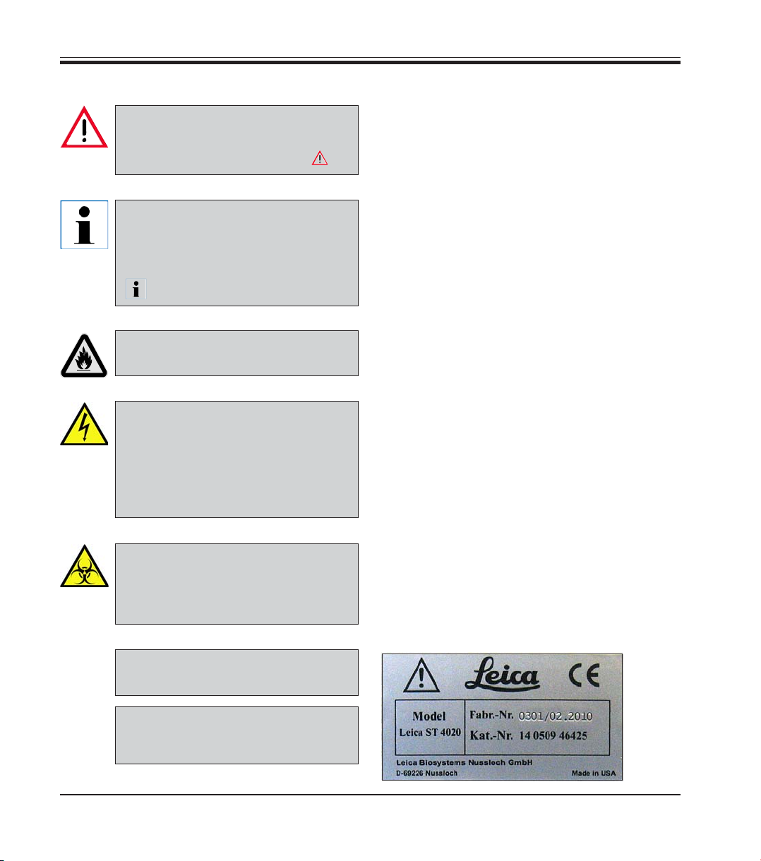
Type
All information contained in this Instructions for
Use applies solely to the instrument type listed
on the cover page. A nameplate indicating the
instrument serial number is attached to the rear
side of the instrument.
6
(5)
RUN
Numbers in brackets refer to item
numbers in figures.
Function keys to be pressed on the
instrument are written in bold-print
capital letters.
Fig. 1
Instructions for Use V1.1, RevB – 10/2012
Page 7
The safety and caution notes in this chapter must be observed at all times.
Be sure to read these instructions, even if you are already familiar with the operation and
use of other Leica products.
2.1 Safety notes
This Instructions for Use contains important instructions and information regarding the operational safety and maintenance of the instrument.
The Instructions for Use is an important part of
the product, and must be read carefully prior to
startup and use and must always be kept near
the instrument.
2. Safety
This instrument has been built and tested in accordance with the safety regulations for electrical measuring, control, regulating, and laboratory devices.
To maintain this condition and ensure safe operation, the user must observe all notes and
warnings contained in this Instructions for Use.
The Instructions for Use must be expanded by corresponding instructions if this becomes necessary due
to existing national regulations on
accident prevention and environmental protection in the country
where the instrument is operated.
The protective devices located on the instrument and the accessories must not be removed or modified. The instrument must only be opened and repaired by service technicians authorized by Leica.
2.2 Warnings
The safety devices installed in this instrument by the manufacturer only constitute the basis for accident prevention. Operating the instrument safely is, above all, the responsibility
of the owner, as well as the designated personnel who operate, service or repair the instrument.
To ensure trouble-free operation of the instrument, make sure to comply with the following
instructions and warnings.
For current information about applicable standards, please refer to the
CE declaration for the instrument and
to our Internet site:
http://www.LeicaBiosystems.com
Leica ST4020
7
Page 8
2. Safety
Hazards – safety regulations on the instrument itself
Warning labels on the instrument marked with a warning triangle indicate that the correct operating instructions (as defined in this Instructions for Use) must be followed when
operating or replacing the item marked. Failure to adhere to these instructions may result
in an accident, personal injury, damage to the instrument or accessory equipment.
Hazards – transport and installation
Once unpacked, the instrument may be transported only in an upright position.
Place the instrument on a laboratory bench and align it horizontally.
The instrument must not be placed in direct sunlight (e.g., next to a window). Avoid
impacts, bright direct light, and excessive temperature fluctuations.
Only connect the instrument to a grounded power socket. The protective effect may not
be eliminated by an extension cable without a protective grounding conductor.
The instrument will automatically detect the voltage/frequency of the power source.
The installation location must be well ventilated, and must contain no sources of ignition
of any kind. The chemicals used in the Leica ST4020 are easily inflammable and hazardous to health.
Do not operate the instrument in rooms with explosion hazard.
Condensation water may form in the instrument, if there is an extreme difference in temperature between the warehouse and the installation site and if air humidity is high at the
same time. In this case, a two-hour waiting period must be maintained before switching
on the instrument.
Warnings – Handling reagents
Take care when handling solvents!
Always wear rubber gloves and safety goggles when handling the chemicals used in this
instrument.
The reagents used can be both toxic and/or flammable.
When disposing of spent reagents, observe the applicable local regulations and the
waste disposal regulations of the company/institution in which the instrument is being
operated.
Do not smoke near the stainer or the reagents.
The stainer should be operated under an extractor hood.
8
Instructions for Use V1.1, RevB – 10/2012
Page 9
Hazards – working with the instrument
The instrument may be operated by trained laboratory personnel only. It must only be
operated for the purpose of its designated use and according to the instructions contained in this manual.
In the event of an emergency, switch off the power switch and unplug the instrument
from the power supply.
The instrument must be positioned so that the connection socket and the power switch
are easily accessible at all times.
The power supply cord must be routed so that it is not likely to be walked on or pinched
by items placed on or against it.
Suitable protective clothing (lab coat, gloves, protective goggles) must be worn when
working with reagents.
There is a danger of fire if a open flame (e.g. Bunsen burner) is used directly beside the
instrument (solvent fumes). Therefore, keep all ignition sources at least 2 meters away
from the instrument!
While the stainer is not in use, keep the reagent containers covered with the Reagent
Cover provided with the stainer.
2. Safety
Hazards – cleaning and maintenance
Before any maintenance, switch off the instrument and unplug it from power supply.
When using cleaners, please comply with the safety instructions of the manufacturer and
the laboratory safety regulations.
Do not use any of the following for cleaning the outside surfaces of the instrument: alcohol, detergents containing alcohol (glass cleaners), abrasive cleaning powders, solvents
containing acetone, chlorine or xylene!
Clean the Hood and the housing with commercial mild household cleaning agents. The
finished surfaces are not resistant to solvents!
Prevent liquids from entering the interior of the instrument while the instrument is being
cleaned or during operation.
Do not use any attachments or accessories not recommended by the product manufacturer as such attachments and accessories may cause hazards, damage the instrument
and void the warranty.
Leica ST4020
9
Page 10
3. Instrument Components and Specifications
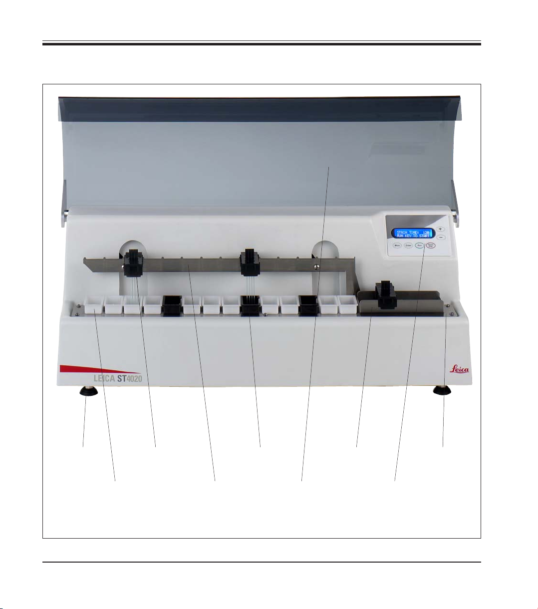
3.1 Overview – Instrument Parts
10
Adjustable
Foot
Reagent
Container
Slide
Carrier
Rinse Station
Lift Bar Hood
(opional)
Exit
Tank
Display
and
Keypad
Platform
Fig. 2
Instructions for Use V1.1, RevB – 10/2012
Page 11
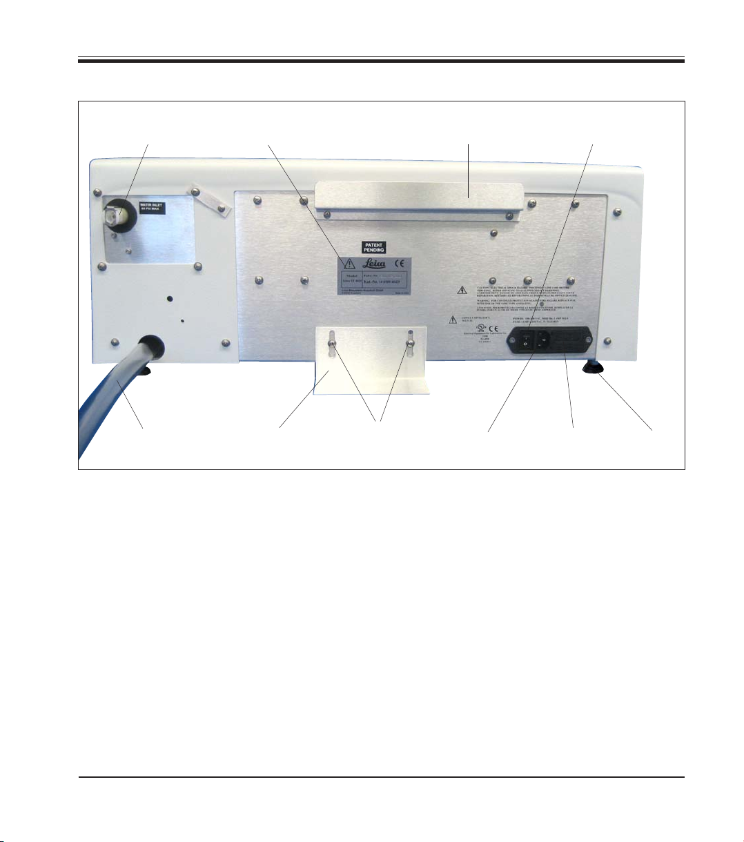
Instrument rear view
3. Instrument Components and Specifications
Rinsing Water
Connection
Waste Water Hose
Identification Label
Support Bracket
for Stabilizing
2 Screws
Support Bracket
3.2 Instrument specifications
The Leica ST4020 is an automatic linear stainer designed for stand-alone use, and can be
used for staining frozen tissue sections in histology labs as well as anatomical pathology
laboratories.
It is ideal for use in staining samples from either
Mohs technique laboratories or sections from
frozen section laboratories or general surgical
pathology. In addition it is intended to be used
in hematology, cytology, as well as performing
routine H & E stains.
Storage for the
Reagent Container Cover
for
Connector for
Power Cord
Power Switch
Power Supply
Adjustable
The user loads the slides in a carrier that can
hold up to 4 slides at a time. The stainer provides 14 reagent stations that can be used as
reagent stations or running rinse water stations
and has an Exit Tank that can hold up to four
processed slide carriers.
The slides will remain in each reagent station for
a fixed programmable time that is applicable to
all stations during staining. Station time, number
of dips and start position are programmable.
Foot
Fig. 3
Leica ST4020
11
Page 12
3. Instrument Components and Specifications
3.3 Functional Description of Components - System overview
Figure 2 on page 10 shows an overview of the stainer.
The Leica ST4020 Linear Stainer has the following functional areas:
13
4
2
4 6
14
Fig. 4
1
3
Fig. 5
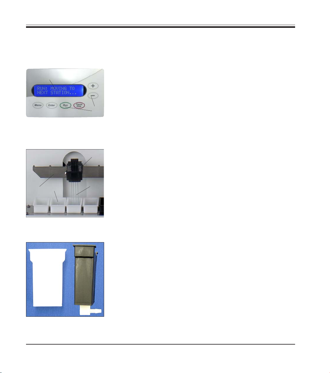
Keypad (14) with Display (13)
A membrane keypad with 6 keys allows the user to set up the
processing parameters and also allows the user to start and stop
the processing runs.
An LCD display consisting of two rows, each row 16 characters
long, in which the progress of slide processing and the stainer's
processing parameters are displayed. The user is directed to take
various actions as necessary.
Slide carrier (1) and lift Bar (2)
The user inserts the slides for staining (3) in the slots of the slide
carrier (1). This is then placed onto the lift bar (2) , by which it is
transferred to the first reagent container.
The lift bar moves the slide carriers from one station to the next
station and eventually deposits them in the exit tank.
Reagent container (4) and Rinsing Water Container (6)
Each reagent container (4) can hold up to 50 ml of the reagent for
staining and processing.
A total of 14 reagent and rinse containers (6) can be arranged to
customize the stainer to carry out a specific staining protocol.
Each of the 14 processing positions must have either a reagent
container or a rinse container present.
12
Fig. 6
The rinse containers allow the slides to be subjected to running
rinse water while the slides are being processed.
Instructions for Use V1.1, RevB – 10/2012
Page 13
3. Instrument Components and Specifications
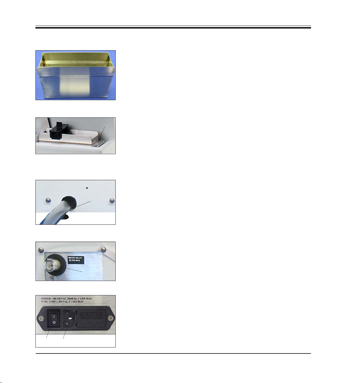
Functional Description of Components (continued)
Exit Tank (7)
The exit tank holds the processed slides. It can hold up to 4 slide
carriers.
7
Fig. 7
Fig. 8
9
As soon as the exit tank is full, the stainer pauses processing until
the slide carriers are removed.
Platform (8)
8
The platform holds the reagent containers, rinse containers and
the exit tank in fixed locations to ensure the proper operation of
the stainer. All 14 containers and the exit tank must be placed on
the platform to ensure proper operation of the stainer.
Waste Water Drain Hose (9)
The waste water drain hose must always be inclined downwards
so that the rinsing water drains into a collecting receptacle or
drainage basin, and cannot collect in the stainer.
11
12
Leica ST4020
10
Fig. 9
Rinsing Water Supply (10)
A connection port for the rinsing water supply is located on the
rear of the stainer. The necessary connecting hose is included in
the equipment supplied.
Fig. 10
Main Switch and (11) Connection to Power Supply (12)
The stainer is connected to the power supply (12) by the power
supply cord, and activated with the main switch (11).
The instrument can be operated with alternating current at 100 to
230 Volt with a power frequency of 50/60 Hz.
Fig. 11
13
Page 14
3. Instrument Components and Specifications
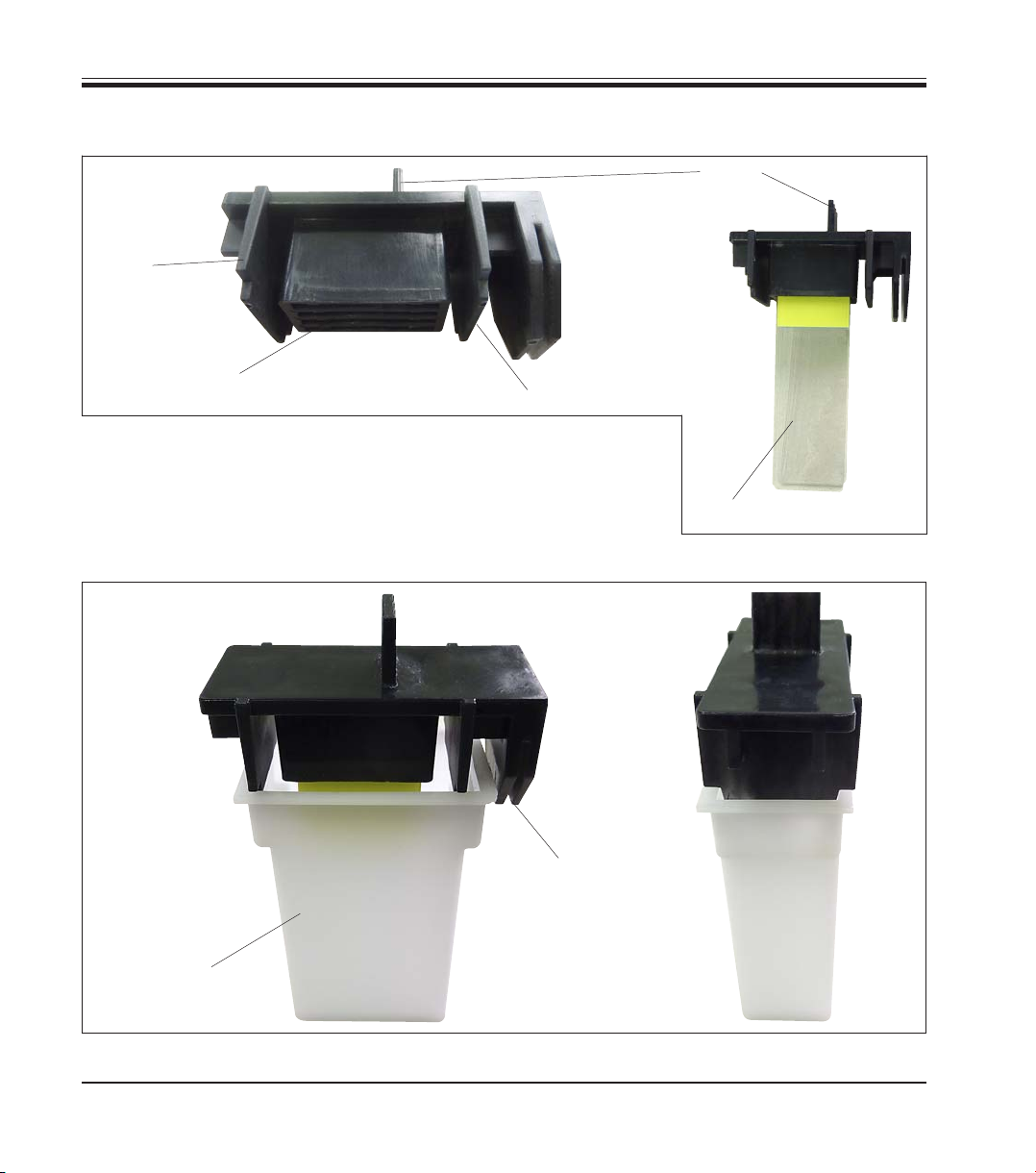
3.3 Functional Areas of the Slide Carrier
Side
Support
Locating Slots
for Slides
Fig. 12 and Fig. 13 show how the slide carriers are to be positioned
over the reagent containers.
While placing a slide carrier with slides for staining in the lift bar,
ensure that the side supports of the slide carrier are aligned so
that the slide carrier is positioned above the container.
Side Support
Handle
Slides
Fig. 12
14
Lift Bar
Retainer
Reagent
Container
Fig. 13
Instructions for Use V1.1, RevB – 10/2012
Page 15

3. Instrument Components and Specifications
3.4 Standard Delivery
The Leica ST4020 standard delivery consists of the following items:
1 Leica ST4020 basic instrument 14 0509 46425
14 Reagent containers (white) 14 0509 46437
3 Water rinse containers (black) 14 0509 46441
3 Slide carrier 14 0509 46438
1 Set of Power cords:
1 Power cord "D" 14 0509 46480
1 Power cord "UK" ST-BU F-5A 14 0509 46481
1 Power cord "US" 14 0509 46479
1 Water inlet hose 14 0509 46532
1 Water drain hose (already installed) 14 0509 46445
1 Rinse Manifold with restrictor (already installed) 14 0509 46533
1 Exit collection tank 14 0509 46450
1 Set with tubings, fittings, tie wraps: 14 0509 46459
1 Water hose 16“ long, Ø1/8“
3 in line fittings
2 plugs
10 tie wraps
1 Support Bracket 14 0509 46570
1 Metal reagent container cover 14 0509 46442
1 Set replacement fuses:
2 Fuses 250 V, T 1.0 A 14 0509 46463
1 Instruction manual for Leica ST4020 “Small Linear Stainer“ 14 0509 80001
Leica ST4020
Please check all delivered parts against the packing list and against your order to verify
whether the delivery is complete! Should you find any discrepancies, please contact your
Leica sales office without delay.
15
Page 16

3. Instrument Components and Specifications
3.5 Technical Data
General
Admissions: UL, cUL, CE
Nominal voltage: 100 V – 240 V +/- 10% AC
Nominal frequency: 50 to 60 Hz
Power draw: 25 VA
IEC 1010 classification: Protective class 1
Pollution degree 2
Overvoltage installation category II:
Secondary fuses: Melting fuses 1.0 A T Ø 5.0 x 20 mm
Operating temperature range: 15°C to 30°C
Relative humidity: 20% to 80%, non-condensing
Altitude:
Dimensions and weights
Dimensions, (W x D x H): 620 mm x 250 mm x 200 mm
Height with Hood open: 430 mm
Dry weight, unpacked: approx. 16 kg
Instrument with accessories: approx. 19 kg
Weight incl. packing material: approx. 21 kg
< 6500 ft (Ambient pressure. 29 - 31 inch Hg)
Performance
Slide processing rate: Depends on program structure and loading
Loading capacity: max. 4 slide carriers
Stations: max. 14
Reagent stations: max. 14
Washing stations: max. 3 (then only 11 reagent stations are possible)
Reagent container volume: 50 ml
Agitation: 0 to 3 dips per station for dwell times > 30 sec.
Throughput rate of washing stations: 250 ml/min +/-100 ml, depending on number of stations
Dwell time adjustment: 2 to 300 sec. at each station
Capacity of the slide carrier: max. 4 slides
Capacity of the exit tank: max. 4 slide carriers
16
Instructions for Use V1.1, RevB – 10/2012
Page 17

4.1 Location Conditions
4. Setting up the instrument
• The instrument requires an installation area of approx. 250 x 700 mm.
A clearance of at least 25 cm must be left between the instrument and
the closest wall or other instruments.
• If the stainer is to be operated with rinsing stations, fresh water and
waste water connections must be no more than 1.2 m from the ports
on the back of the instrument.
• It must be ensured that there is sufficient clear space (approx. 30 cm)
above the instrument to allow unobstructed opening of the optional
Hood.
• Room temperature consistently between +10°C and +30°C.
• Relative air humidity maximum 80%, non-condensing.
• Practically vibration-free floor. Avoid vibrations, direct sunlight and
heavy variations in temperature.
The chemicals used in the Leica ST4020 are easily inflammable
and hazardous to health.
The installation site for the Leica ST4020 must be well ventilated, and there must be no ignition sources of any kind in the
area.
The instrument must not be operated in areas at risk of
explosion.
4.2 Unpacking the Instrument
• Open the packaging.
• Remove all foam material.
• Take out all accessories and the Instructions for Use.
• Check the contents of the delivered pack against the order form to
ensure that all components and accessories are included.
Leica ST4020
First check the shipment for external damages upon arrival.
If it is evident that the shipment was damaged during transport,
please make a claim to the carrier immediately.
17
Page 18

4. Setting up the instrument
Unpacking the Instrument (continued)
These unpacking instructions only apply if the box is placed with the symbols
facing upwards for unpacking.
35
36
Fig. 14
1. Cut through the packing tape (35) on the top edge
of the box.
2. Remove the yellow envelope with "Documents of
Conformity" (36) and store in a safe place.
38
Fig. 16
4. Use the molded foam pads (38) to pull the
instrument out of the inside packaging
and place it on a firm laboratory bench.
5. Pull the molded foam pads (38) away from the
sides of the instrument.
Remove the protective film (40) from the instrument.
38
37
3. Remove the Accessories (37) , packaging material (39) and Instructions
for Use.
40
39
Fig. 15
38
Fig. 17
18
Fig. 18
6. The instrument must now be prepared for correct
use in accordance with the instructions in the
accompanying Instructions for Use.
The packaging must be retained for the
duration of the warranty period.
To return the instrument, follow the
instructions above in reverse order.
Instructions for Use V1.1, RevB – 10/2012
Page 19

4. Setting up the instrument
4.3 Setup
25
28
27
26
Fig. 19
29
Fig. 20
Horizontal Alignment
For safe and accurate work, it is important that
all instrument feet are in uniform contact with
the installation surface.
The stainer is horizontally aligned at the factory.
If a completely level or horizontal surface is not
available at the installation site, the instrument
must be realigned.
For this purpose, the instrument feet (25) are
height-adjustable.
• For alignment, loosen the locknuts (26) using
7
a size
/16" open-end wrench.
• Adjust the instrument feet (25) until the
instrument is in a stable position at the
installation location according to requirements.
• Retighten the locknuts.
Mounting the Support Bracket
To ensure that the instrument cannot tip over
when its keys are pressed, the support bracket
(27) must be mounted on the rear.
• To do this, first unscrew the two Philips head
screws (28) with a screwdriver. Place them
together with the two associated washers
(29)
• Place the support bracket against the rear of
the instrument (
Fig. 20), reinsert but do not
fully tighten the two screws.
• Press the support bracket down onto the
support surface until a face of the plate lies
flush with the bench surface, then tighten
the plate in this position.
Leica ST4020
19
Page 20

4. Setting up the instrument
4.4 Water Connection
37
10
• Run the drain hose (9) into a suitable collecting tank or waste basin. Make sure that the
hose is not kinked and that the water is able
36
35
to drain freely downwards.
• Then connect the rinsing water supply (35)
to the stainer.
• To do this, push the connector (36) into the
orifice (10) on the instrument until it clicks
into place. To detach the hose, press on the
plate (37) and pull the connector back.
• Connect the other end of the hose to a suitable water tap. Do not open the water supply
yet!
9
Fig. 21
Adjustment of the rinsing water flow rate is
described in
Chapter. 5.4.
4.5 Installing the Rinsing Water Containers
Up to three rinsing stations may be provided on the stainer. The rinsing water containers can
be located at any of the 14 reagent stations.
The equipment supplied includes three hoses with Y-connectors. The cable ties on these
Y-connectors must not be removed. Also, do not detach the Y-connectors from the associated
hoses.
Watertight, functional rinsing stations in accordance with the desired staining protocol can be
set up with the aid of additional cable ties, hoses, plugs and connectors that are also included
in the scope of delivery.
20
While the rinsing stations are being set up, it must be ensured that the rinsing water
containers are positioned horizontally on the platform, and all hoses are lying horizontally on the bottom of the drainage tank, outside of the travel path of the lift bar.
The rinsing water hoses must not be subjected to any kind of pulling or stretching
stresses.
Instructions for Use V1.1, RevB – 10/2012
Page 21

Installing the Rinsing Water Containers (continued)
4. Setting up the instrument
Fig. 22 shows how the hoses
are routed in the instrument.
If you want to work entirely
without water, no further steps
are necessary – simply do not
connect a water supply line to
the instrument.
Hose 1
Hose 2
Hose 3
Area of the
drainage tank
Fig. 22
Place the rinsing water containers (6) in the desired position on the platform. The rinse
container bar fitting pointed (5)
to the exit tank (refer to
fig. 23).
Start with the station closest to
the drainage tank.
6
5
Fig. 23
The hose (15) should run level
along the bottom of the instrument.
Mark the end of the hose that
will connect to the rinsing
water container.
This is "Marking 1".
Leica ST4020
15
Marking 1
Fig. 24
21
Page 22

4. Setting up the instrument
Installing the Rinsing Water Containers (continued)
Lateral surface of the connector
End of the connector
• Now take the rinsing water
container and the hose out
of the stainer.
• Align Marking 1 on the end
of the connector and make
a second marking ("Marking 2") to indicate the lateral
surface of the connector
(Fig. 25).
Marking 2
Marking 2
Marking 1
21
• Cut the hose off at Marking 2.
Fig. 25
• Then push the hose (21)
fully onto the connector by
twisting until the end of the
hose is flush against the
lateral surface of the connector (Fig. 26).
• If the hose is not pushed
completely onto the connector, it may become
detached as soon as the
water supply is turned on.
22
Do not stretch tubing to fit on the fitting.
Fig. 26
Instructions for Use V1.1, RevB – 10/2012
Page 23

Installing the Rinsing Water Containers (continued)
• Place the rinsing water container back in the desired position on the
platform. Check that the rinsing water container is positioned horizontally on the platform.
If the hose is too long, the rinsing water container will tilt to the right; if
it is too short, it will tilt to the left.
If the rinsing water container is not positioned horizontally on
the platform, it cannot be guaranteed that the stainer will function properly.
• Repeat the steps described above for the other rinsing stations.
If only one or two rinsing stations are required,
the hoses that are not used must be sealed with
a plug (17), see Fig. 27.
17
18
• To do this, twist and push the plug fully into
4. Setting up the instrument
the end of the hose, and then secure it with
a cable tie (18).
Leica ST4020
Fig. 27
If two rinsing stations are to be located immediately beside one another, the connector (19) for
the left station must be aligned as shown in
Fig. 28.
19
Fig. 28
23
Page 24

4. Setting up the instrument
4.6 Remedy if Hose is too short
If the hose (21) at one of the stations should be too short, or if a hose has
been cut too short by mistake, the following remedy may help:
20
18
21
Fig. 29
• Cut the hose roughly in the middle between the Y-connector and the
rinsing station.
• Use the extension connector (20) included with the package to attach
an additional hose section (21) of the required length.
• To do this, measure the length of the hose again, and if necessary cut
it to exactly the required length.
• Push both ends of the hose as far as they will go onto the extension
connector, and then secure each hose with a cable tie (18).
• Finally, check again that the rinsing water container is positioned
horizontally on the platform.
24
Instructions for Use V1.1, RevB – 10/2012
Page 25

5.1 Switching on the Instrument
The instrument MUST be connected to a grounded power socket.
Only the power cord provided may be used, which is intended for the local power
supply (socket). The protective effect must not be eliminated by an extension cable
without a protective grounding conductor.
The AC socket used for the power supply must be close to the instrument and easily
accessible.
11
12
5.2 Control Panel Functions
Fig. 30
5. Operation
• Before plugging the instrument into the
mains, make sure that the main switch (11)
on the rear of the instrument is in the
OFF ("0") position.
• Plug the power cable into mains power supply socket (12) and connect it to the power
socket on the wall. If applicable, switch on
the switch for the power socket.
• Then switch on the main switch (11) on the
instrument, (ON = "I").
The control panel consists of a membrane keypad with six pressure keys, and a screen consisting of a two-line display, each line being 16 characters long.
This is used for controlling the functions of the instrument and for programming the software.
The current state of the stainer and ongoing operations are displayed while a staining task is
being processed.
• The instrument will take a few seconds to
initialize. During this time, the installed version of the software will be displayed on the
monitor.
• Then, the lift bar performs a circular motion
to ensure that the bar is in the correct position at the start of staining.
The message FINDING HOME... is displayed
on the screen.
Fig. 31
Leica ST4020
25
Page 26

5. Operation
Control Panel Functions (continued)
There are six push-buttons on the control panel, and these are used to adjust the operating parameters and control the instrument.
The keys have been assigned the following functions:
The operating parameters can be displayed and checked with the MENU
key.
Each time the MENU key is pressed, another one of the six operational
parameters will be displayed.
Whenever a new setting is made, it will take effect immediately. Furthermore, since all settings are saved in memory, it will automatically be used
the next time the system is powered up.
The operating parameter that is currently being displayed can be raised or
lowered by pressing the PLUS ("+", increases the displayed value) and
MINUS ("-", reduces the displayed value) keys respectively.
Pressing the PAUSE/STOP key allows the operator to exit the setup menu
without changing the parameter currently being displayed.
While running:
Pressing PAUSE/STOP once interrupts the current staining operation so
that another slide carrier can be placed in the lift bar.
Pressing PAUSE/STOP twice (in quick succession) terminates the current
program, and the system returns to idle mode.
26
If the ENTER key is pressed, the selected parameter is stored in the
system.
The system returns to its idle mode whenever a new setting is entered, or
whenever the user exits the setup menu by pressing the PAUSE/STOP
key,
Pressing the RUN key starts a staining operation on the basis of the values
shown in the display. At the same time, the flushing valve is activated, the
display changes, and the timer appears, counting down to show the remaining processing time.
Instructions for Use V1.1, RevB – 10/2012
Page 27

5. Operation
5.3 Setting the Operating Parameters
The process of adjusting the operational parameters is simple and direct.
When the system is "ON" and in the idle mode (that is, neither RUNNING nor in a SETUP mode),
the operator may display and check the setup parameters by pressing the MENU key.
If the ENTER key is pressed, the selected parameter is stored in the system.
Pressing the PAUSE/STOP key allows the operator to exit the setup menu without changing
the parameter currently being displayed.
Whenever a new setting is made, it will take effect immediately.
Furthermore, since all settings are saved in memory, it will automatically be used the next time
the system is powered up.
The system returns to its idle mode whenever a new setting is entered, or whenever the user
exits the setup menu by pressing the PAUSE/STOP key.
Processing time
Leica ST4020
The amount of time that the slides are immersed at each station
can be varied from 2 to 300 seconds.
• When the PLUS or MINUS key is pressed ("+" or "-"), the staining time is altered:
one second at a time in a range from 2 to 30 seconds,
five seconds at a time in a range from 30 to 60 seconds,
ten seconds at a time in a range from 60 to 300 seconds.
• After ENTER is pressed, the new processing time is activated,
and this time is stored for future use.
27
Page 28

5. Operation
Display Contrast
Transfer Mechanism Calibration
The contrast on the liquid crystal display can be adjusted
according to the preferences of individual users.
• The adjustment range is between 1 and 15, 1 being the brightest setting.
• Pressing the PLUS or MINUS key changes the number of
contrast for the display.
• After ENTER is pressed, the setted contrast is stored.
The position at which the transfer movement is paused and
processing started may be adjusted by pressing the PLUS (+) or
MINUS (-) keys, followed by the ENTER key.
• Pressing the PLUS or MINUS key changes the number of
steps carried out by the stepping motor by 8. The minimum
permitted value is 704, the maximum permitted value is 1000.
The typical setting is 944 to 960.
• After ENTER is pressed, the number of steps is stored. Also,
the transfer mechanism advances to the next station, stopping when the selected number of steps has been taken.
Number of Dips
28
The number of dips that are carried out for uniform staining can
be set in a range from 0 to 3.
• Pressing the PLUS or MINUS key changes the number of dips
carried out by the instrument.
• After ENTER is pressed, the number of dips is stored.
If a value of 1, 2 or 3 has been selected, the system dips the slide
carriers the corresponding number of times as soon as they
reach a station.
All subsequent dip motions are carried out at intervals of 20 seconds each if the processing time is 30 seconds or more. If the
processing time is less than 30 seconds, then no dips will occur,
regardless of the setting selected.
Instructions for Use V1.1, RevB – 10/2012
Page 29

Start position
Run Forever
5. Operation
The start position has to be set if staining protocols that do not
make use of all 14 staining positions are being run.
In order to make the processed slides available to the user at the
exit tank in the least amount of time possible, a programmable
start position feature has been added.
• Pressing the PLUS or MINUS key changes the number of
start position carried out by the system.
• After ENTER is pressed, the start position is stored.
The user can specify which station is being used for the start
position.
• For example, a protocol that requires only ten stations could
use stations 5 through 14 rather than beginning at the first
station.
• This puts the slides into the exit tank as soon as they leave
the last process station. By specifying the start position as
position 5, the user allows the system to issue its "reminder
beep" at the correct time.
• This beep informs the operator that slides have reached the
exit tank.
Leica ST4020
There are two settings, and these can be set using the PLUS or
MINUS keys.
• With a setting of "00", the stainer runs for as long as slide
carriers are loaded into it and are undergoing the staining
process.
• A beep sounds every time a slide carrier is ready. When
3 racks have reached the exit tank, a signal sounds 5 times.
• With the "01" setting, the stainer runs continuously whether it
is loaded or not. A beep sounds every time a slide carrier is
ready.
• After ENTER is pressed, the run mode is stored.
29
Page 30

5. Operation
5.4 Setting the Rinsing Water Flow Rate
To set the flow rate for the rinsing water, proceed as follows:
• First set a staining time of 60 seconds. To do this, press
MENU once, and then press the PLUS or MINUS key repeatedly until a processing time of 60 seconds is displayed.
• Then press the ENTER key to confirm this processing time.
• Now press RUN. The countdown of station time will be displayed while the rinse water valve inside the unit activates.
30
2x
• Now slowly turn on the tap to which the supply hose is connected, and adjust the flow rate so that water flows into the
rinsing water container at a sufficient rate and the rinsing
water can drain without obstruction.
DO NOT adjust the flow rate too high. This can cause
spills on the platform to the next stain station or can
overflow the drain area of the stainer.
• Once the flow rate is adjusted properly, press the
PAUSE/STOP key twice, and then press the ENTER key to
reinitialize the mechanism when prompted by the instrument.
Instructions for Use V1.1, RevB – 10/2012
Page 31

5. Operation
5.5 Processing Slides
The Leica ST4020 Stainer is a relatively simple and trouble-free system. The user must inform
the system via the keypad whenever slides are to be added to or removed from the stainer.
Directions as to how this is done appear in the following sections. Slides must be loaded and
unloaded in the prescribed fashion.
Important!
Failure to follow the directions given here may result in improper or incomplete
processing of slides.
correctly
arranged
slide carrier
• The slide carrier must be prepared carefully,
because if it is positioned incorrectly, the
slides may not be properly transported by
the lift bar.
There are two occasions that slides may be
loaded onto the start position:
• before the start of processing, and
• after the start of processing.
In both cases, the slides will be immersed in the
start position's reagent.
The user should be prepared to start or resume
the staining run as soon as the slide carrier is in
position, so that extra staining time may be kept
to a minimum.
Reagent
Container
Leica ST4020
Fig. 32
31
Page 32

5. Operation
5.5.1 Starting a staining run
It is, of course, the user's responsibility to verify that each of the setup parameters (station
time, number of steps, number of dips, etc.) is set to an acceptable value before slides are
placed in the starting position and RUN is pressed.
Slides should not be loaded while the user is verifying setup parameters, because changing
the number of steps ("transfer mechanism calibration") will cause the transfer mechanism to
advance to the next position!
All parameters should be verified BEFORE loading the first set of slides.
A staining run cannot be started unless the stainer is in standby-mode.
In this mode, the system displays the process time and instructions to press the RUN key to
start:
When the RUN key is pressed, the flushing valve is actuated, the
display changes and the remaining processing time appears,
counting downwards:
When a staining run is started by pressing the RUN key, the
system receives the information that there are slides in the start
position that are to be stained.
32
Note that the first station's process time begins as
soon as the RUN key is pressed. This means that the
slide carriers must be loaded in the start position
immediately before the RUN key is pressed.
• The stainer will continue running until these slide carriers are
transferred from station 14 to the exit tank.
• The current operation appears successively in the display.
• When the last slide carrier has been transferred to the exit
tank, the system stops the process and returns to IDLE mode,
unless more slides are inserted in the correct manner.
Instructions for Use V1.1, RevB – 10/2012
Page 33

5. Operation
5.5.2 Adding more slide carriers during a staining run
The PAUSE/STOP function can be used to allow additional slide carriers to be placed in the
instrument after processing has begun.
The following procedure should always be followed:
If a staining run is already underway and more slide carriers are
to be inserted, press the PAUSE/STOP key once.
Important!
Only press PAUSE/STOP ONCE!
If this key is pressed twice, the entire staining run
will be aborted.
Please wait, and do not add any
further slides!
This message is displayed until
the slide carriers have been removed from a position by the lift
bar and transferred to the next
station.
When:
LOAD SLIDES...
PRESS RUN
appears in the display, the new slide carriers must be inserted at
the start position immediately, and the RUN key pressed.
As soon as the RUN key is pressed, the system resumes processing, and continues counting down the process time.
It should also be noted that the entire operation is interrupted
until the RUN key is pressed again.
Therefore, the operator should be prepared to load the new
slides as quickly as possible and should then press the RUN key
quickly to avoid having all slides already in the system spend
extra time immersed.
Leica ST4020
33
Page 34

5. Operation
5.5.3 Temporarily pausing a staining run
If the PAUSE/STOP and RUN keys are pressed in this order, the
instrument receives the information that more slide carriers
have been inserted at the start position.
The stainer continues operating until these slide carriers are
transferred from station 14 to the exit tank.
If no other slides have been added in the meantime, it emits an
audible signal to alert the operator that the staining run has
been completed. A corresponding message appears in the
display.
This procedure applies for inserting slide carriers after processing has begun, and must be followed under all circumstances.
Attempting to add slide carriers without pressing the
PAUSE and RUN keys will result in the carriers not
being transported to all of the stations, since the
stainer will not know that additional slide carriers
have been added!
Occasionally, it may be necessary to stop the system when it is processing slides. This too can
be accomplished with PAUSE/STOP key.
Staining can be interrupted,
• to allow access to the instrument if anomalies requiring such arise during staining.
• so that reagents can be checked, and changed if necessary.
Important!
The lift bar will complete the current cycle, and will
move the slide carriers to the next station. Do not
attempt to open the instrument until "LOAD SLIDES...
PRESS RUN" appears in the display.
34
Instructions for Use V1.1, RevB – 10/2012
Page 35

5. Operation
5.5.4 Ending a staining run prematurely
The role of the PAUSE/STOP key in loading additional slides was described in the previous
chapter.
However, this key has a second function, that of terminating a staining run that has already
been started.
It has been noted already that the PAUSE/STOP key should be
2x
pressed only ONCE when additional slides are to be loaded.
Because if the PAUSE/STOP key is pressed TWICE, processing
is stopped. If this happens, the message opposite appears in the
display.
• This means that the staining run has been aborted, and the
instrument must be reset by pressing ENTER.
Important!
All slide carriers must be removed from the instrument, because all the information in the software has
been reset.
Leica ST4020
• As soon as the user presses the ENTER key in this situation,
the transfer mechanism returns to the home position. This is
then the same situation as when the instrument is first
switched on.
• The corresponding message appears in the display.
• As soon as the transfer mechanism reaches the start position, the stainer returns to idle mode; then, the same status
message is displayed as the one shown when the instrument
is initialized after it is switched on.
35
Page 36

5. Operation
5.5.5 Removing Processed Slides
Removing processed slides means more than the mere physical act of removing slides.
It also involves informing the instrument that slide carriers have been removed, so that the
stainer may keep an up-to-date count of how many slide carriers are still in the system.
• Every time the system transfers a slide carrier from station 14 to the exit tank, an audible
signal (beep) is emitted to inform the user that slides are available for removal.
• The system also increments its count of the number of slide carriers that are in the exit
tank.
• The operator should remove processed slides as quickly as possible.
• The exit tank can hold up to four slide carriers. This enables the operator to remove the
slides at a more convenient time.
• As soon as there are 3 slide carriers in the exit tank, the stainer emits a distinctive audible
signal to alert the operator.
• In this case, the slides should be removed immediately, before the counter in the system is
set to 4;
Important!
As soon as there are four slide carriers in the exit tank, the stainer stops processing, because the exit tank cannot hold any more slides.
• It is often convenient to insert new slides for staining at the same time as the processed
slides are being removed.
In this case it may be assumed that the operator normally removes all the stained slides
from the exit tank every time new slides are loaded.
36
Instructions for Use V1.1, RevB – 10/2012
Page 37

5. Operation
Removing Processed Slides (continued)
Of course, there will be times when slides are being removed but no additional slides are being
loaded.
These two different situations are handled in the following ways:
1 To remove processed slides only:
• Take ALL of the slide carriers out of the instrument's exit
tank.
• Press the RUN key once to start processing the loaded slide
carriers.
2. To remove the carriers with stained slides and load fresh
slide carriers:
Leica ST4020
• Press the PAUSE/STOP key once.
• Wait until the system prompts you to load the slides and
press the RUN key.
• Place the new slide carriers in the system.
• Press the RUN key once.
• Remove ALL the slides from the exit tank.
37
Page 38

6. Cleaning and Maintenance
6.1 Cleaning the Instrument
Prior to cleaning the instrument, always switch off power supply and unplug the
power cord!
When using cleaners, comply with the safety instructions from the manufacturer
and the labor-safety regulations at your laboratory.
Dispose of spent reagents in accordance with the laboratory guidelines in force in
your country!
Wipe off spilled solvents (reagents) without delay! The Hood surfaces only have
moderate resistance in the event of prolonged contact with solvents!
The painted surfaces and the control panel of the instrument are not resistant to
xylene or acetone!
Do not use any of the following for cleaning the outside surfaces of the instrument:
alcohol, detergents containing alcohol (window cleaner!), abrasive cleaning
powders, solvents containing acetone or xylene!
No liquid must be allowed to come into contact with the electrical connections or
get inside the instrument!
Instrument interior
Remove the reagent and rinsing water containers. To clean the stainless steel inner walls, use
a normal detergent and then rinse thoroughly with water.
Lift bar
Wipe the surfaces of the lift bar with a damp cloth.
Instrument exterior
The outer surfaces can be cleaned with a mild detergent and wiped off afterwards with a
damp cloth.
Do not use any solvents for cleaning the outer surfaces and the Hood!
Slide carrier
Clean with domestic or laboratory cleaning agents as necessary.
Drain
The drain hose must periodically be checked for contamination, particularly by algae, and bacteriasl cleaned as necessary.
In order to prevent by algae and bacterial contamination, the drainage system can be flushed
with a 5% solution of sodium hypochlorite. However, metal parts must not remain in contact
with this solution for prolonged periods (e.g., overnight). Flush thoroughly with water afterwards.
38
Instructions for Use V1.1, RevB – 10/2012
Page 39

6. Cleaning and Maintenance
Cleaning the Instrument (continued)
Reagent container and rinsing water container
The reagent and rinsing water containers must be cleaned regularly in order to achieve consistently good staining results.
They can also be cleaned in the dishwasher at a max. temperature of +65°C. Any standard
cleaning agent for laboratory dishwashers may be used.
Caution!
The stations must not be exposed to elevated temperatures (e.g., in industrial dishwashers, which operate at a temperature of +85°C), because the heat can deform
the stations!
6.2 Maintenance Instructions
Only authorized and qualified Leica service personnel may repair the instrument
and access the instrument’s internal components.
For your safety, never attempt to repair the instrument yourself.
Unauthorized repairs will render any claims under the warranty null and void.
See also the section on "Warranty" in Chap. 8 on this matter.
The instrument is basically maintenance-free.
To ensure trouble-free operation of the instrument over a long period of time, the following is
recommended:
• Have the instrument checked at least 1 x year by a qualified service technician authorized
by Leica.
• At the end of the warranty period, enter into a service contract. For more information,
please contact your local Leica technical service center.
Leica ST4020
39
Page 40

7. Troubleshooting
In the following table there is a list of the most common problems which can arise
while working with the instrument, along with possible causes and troubleshooting
procedures.
If faults occur that cannot be corrected with the recommended procedures, or if
they occur again, Leica Service Support must be informed immediately.
7.1 General
The Leica ST4020 is equipped with a simple fault detection system, and can identify certain
movement errors automatically.
• If an operation error is detected, the transfer mechanism will first stop moving.
• It will then back up a short distance, stop again, and then move forward in a second
attempt to reach the desired position.
• If this error recovery attempt is successful, processing continues normally.
7.2 Alarms
• However, if the second attempt to reach the position for
advancing the slide carriers is also unsuccessful, the system
emits a continuous audible alarm.
• The message shown here also appears in the display.
40
• As soon as the PAUSE/STOP key is pressed, the system
• In this event, any staining run currently in progress is termi-
returns to the start position, reinitializes, and switches to idle
mode.
nated and must be restarted.
Instructions for Use V1.1, RevB – 10/2012
Page 41

7.3 Fault Detection and Correction List
Possible causeIssue Corrective action
7. Troubleshooting
• The instrument cannot be
started up
• Display appears blue, but
no text is visible.
• Unit powers up, but the
transfer mechanism does
not initialize.
• The power supply cord is
not plugged into wall outlet
properly.
• The power supply cord is
not plugged into the stainer
properly.
• The power supply in the
instrument is faulty.
• The contrast may have to
be adjusted again.
• The control board in the
instrument is faulty.
• The main mechanism is
jammed.
• The motor seems to turn,
but the Lift bar does not
move because a belt is
worn or broken, or a set
screw on the motor has
come loose.
• Check the cable connections at both ends, replace
the power supply cord if
necessary.
• Inform Technical Service.
• Adjust the contrast as
described in
• Inform Technical Service.
• Check for visible external
obstruction and remove as
necessary.
Chapter 5.3.
• The motor does not turn.
Leica ST4020
• Motor or control board faulty.
• Inform Technical Service.
41
Page 42

7. Troubleshooting
Possible causeIssue Corrective action
• Keypad does not respond to
key presses
• Water does not flow. • Water hose is not
• Water overflows at the rinse stations.
• The keypad or the control
board is faulty.
connected.
• Tap is not open.
• The valve in the instrument
is faulty (does not open) or
the control board is faulty.
• Tap is open too far.
• The drain hose is clogged.
• Inform Technical Service.
• Connect the water hose to
the stainer and the tap.
• Turn on the tap.
• Inform Technical Service.
• Adjust the flow rate for the
rinsing water at the tap as
described in Chap. 5.4.
• The drain hose must not be
kinked.
• Check the drain hose for
objects that might block it.
42
• The drain hose is routed
incorrectly, gradient
insufficient.
• Place the drain hose so that
water does not have to rise
above the level of the drain
fitting.
Instructions for Use V1.1, RevB – 10/2012
Page 43

7. Troubleshooting
7.4 Power Failure
• Check whether there is a general power failure (no power).
• Check whether the power cord is inserted correctly into the power socket and whether the
power socket is switched on, if applicable.
• Check whether the power cable is plugged into the socket on the instrument properly.
• Check whether the power switch is switched on correctly.
• Some instrument malfunctions / failures are caused by defective fuses.
Check whether one or both secondary fuse(s) is/are faulty.
Before replacing a fuse, always switch the instrument off and unplug from power
supply. Defective fuses may be replaced only with the replacement fuses supplied
together with the instrument.
To replace a fuse, proceed as follows:
• With a screwdriver (30), carefully push out
the Hood (34) of the fuse insert (31) at rear of
instument and and open it upwards.
(Fig. 33).
30
33
Leica ST4020
34
31
32
Fig. 33
• Remove the fuse insert (31) – it contains two
fuses (32) on its rear.
• Check that the thin wire (33) in the glass
capillary of a fuse is intact. If not, the fuse
must be replaced.
Before plugging the power cable
back in and switching on the instrument, you must have identified and
corrected the cause of the faulty
fuse.
• Insert the fuse insert with the two fuses and
start up the instrument again.
43
Page 44

8. Optional accessories
8.1 Ordering information
Reagent Containers (6 in a pack) ............................................................................................... 14 0509 46437
Reagent Containers (48 in a pack) ............................................................................................ 14 0509 46439
Slide Carriers (4 in a pack) .......................................................................................................... 14 0509 46438
Slide Carriers (48 in a pack) ........................................................................................................ 14 0509 46440
Rinse Station (1container, 1 rinse nozzle, 1 fitting, 1 tubing).................................................. 14 0509 46441
Rinse Tubing (24" long; Ø 1/8”) .................................................................................................... 14 0509 46457
Tubing and Fitting Kit (48” rinse vessel tubing - Ø 1/8", 2 Y fittings, 3 in-line fittings,
2 plugs, 10 tie wraps).................................................................................................................... 14 0509 46459
Water Inlet Hose Assembly (with fitting, in-line filter, and 4 hose clamps,
2 brass fittings, 5' long, Ø 1/4" reinforced tubing) .................................................................... 14 0509 46443
Water Inlet Hose Assembly (with fitting, 2 hose clamps, 5' long, Ø 1/4" reinforced tubing,
no in-line filter) .............................................................................................................................. 14 0509 46532
Adapter kit for Water Inlet Hose Connection to Faucets (including one with
male thread) .................................................................................................................................. 14 0509 46444
3
/4” NPT
Drain Hose (5' long, Ø 5/8”), 1/8" tie wrap ................................................................................. 14 0509 46445
Exit Tank ......................................................................................................................................... 14 0509 46450
Support Bracket ............................................................................................................................ 14 0509 46570
Stabilizer Bar ................................................................................................................................. 14 0509 46451
Reagent Container Cover (metal) ............................................................................................... 14 0509 46442
Optional Plexiglas Hood............................................................................................................... 14 0509 46478
North American Power Cord ...................................................................................................... 14 0509 46479
European Power Cord .................................................................................................................. 14 0509 46480
British Power Cord ....................................................................................................................... 14 0509 46481
44
Instructions for Use V1.1, RevB – 10/2012
Page 45

Fig. 34
8. Optional accessories
Reagent Containers
6 in a pack
Order-No. 14 0509 46437
48 in a pack
Order-No. 14 0509 46439
Slide Carriers
4 in a pack
Order-No. 14 0509 46438
48 in a pack
Order-No. 14 0509 46440
Leica ST4020
Fig. 35
Rinse Station
1 container, 1 rinse nozzle, 1 fitting, 1 tubing
Order-No. 14 0509 46441
Fig. 36
45
Page 46

8. Optional accessories
Rinse Tubing
24" long; Ø 1/8”
Order-No. 14 0509 46457
Fig. 37
Tubing and Fitting Kit
48” rinse vessel tubing - Ø 1/8”, 2 Y fittings, 3 inline fittings, 2 plugs, 10 tie wraps
Fig. 38
46
Order-No. 14 0509 46459
Water Inlet Hose Assembly
with fitting, in-line filter, and 4 hose clamps, 2
brass fittings, 5' long, Ø 1/4" reinforced tubing
Order-No. 14 0509 46443
Fig. 39
Instructions for Use V1.1, RevB – 10/2012
Page 47

Fig. 40
8. Optional accessories
Water Inlet Hose Assembly
with fitting, 2 hose clamps, 5' long, Ø 1/4" reinforced tubing, no in-line filter
Order-No. 14 0509 46532
Adapter kit for Water Inlet Hose Connection to
Faucets
including one with 3/4” NPT male thread
Order-No. 14 0509 46444
Leica ST4020
Fig. 41
Drain Hose
5' long, Ø 5/8”), 1/8" tie wrap
Order-No. 14 0509 46445
Fig. 42
47
Page 48

8. Optional accessories
Exit Tank
Order-No. 14 0509 46450
Fig. 43
Support Bracket
Order-No. 14 0509 46570
48
Fig. 44
Stabilizer Bar
Order-No. 14 0509 46451
Fig. 45
Reagent Container Cover,
metal
Order-No. 14 0509 46442
Fig. 46
Instructions for Use V1.1, RevB – 10/2012
Page 49

Fig. 47
Fig. 48
8. Optional accessories
Optional Plexiglas Hood
Order-No. 14 0509 46478
North American Power Cord
Order-No. 14 0509 46479
European Power Cord
Order-No. 14 0509 46480
Fig. 49
Leica ST4020
British Power Cord
Order-No. 14 0509 46481
Fig. 50
49
Page 50

8. Optional accessories
Packaging,
with foam, outer carton, bubble wrap, and accessory box) with packaging instructions
Order-No. 14 0509 46455
Fig. 51
Outer Carton Only
Order-No. 14 0509 46456
50
Fig. 52
Instructions for Use V1.1, RevB – 10/2012
Page 51

Warranty
Service information
9. Warranty and service
Leica Biosystems Nussloch GmbH guarantees that the contractual product delivered has been subjected to a comprehensive quality control procedure based on the Leica in-house testing standards, and that the product is faultless and complies with all technical specifications and/or
agreed characteristics warranted.
The scope of the warranty is based on the content of the concluded
agreement. The warranty terms of your Leica sales organization or the
organization from which you have purchased the contractual product
shall apply exclusively.
If you are in need of technical customer service or spare parts, please
contact your Leica representative or the Leica dealer where you
purchased the unit.
Please provide the following information:
• Model name and serial number of the instrument.
• Location of the instrument and name of the person to contact.
• Reason for the service call.
• Delivery date
Decommissioning and disposal
The unit or parts of the unit must be disposed of according to existing
local applicable regulations.
Leica ST4020
51
 Loading...