

Page 1
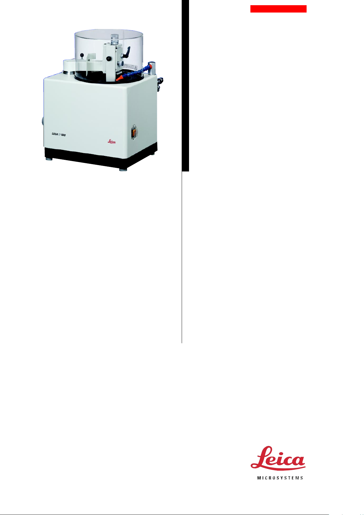
Leica SP1600
Saw Microtome
Instruction Manual
Leica SP1600 – Saw Microtome
V1.1 English - 12/03
Always keep this manual near the instrument!
Read carefully prior to operating the instrument!
Page 2

Page 3
Leica SP1600 – Saw Microtome
The information, numerical data, notes and value judgments contained in this manual represent the current
state of scientific knowledge and state-of-the-art technology as we understand it following thorough investigation in this field.
We are under no obligation to update the present
manual according to the latest technical developments, nor to provide our customers with additional
copies, updates etc. of this manual.
For erroneous statements, drawings, technical illustrations etc. contained in this manual we exclude liability
as far as permissible according to the national legal
system applicable in each individual case. In particular, no liability whatsoever is accepted for any financial loss or consequential damage caused by or related to compliance with statements or other information
in this manual.
Statements, drawings, illustrations and other information as regards contents or technical details of the
present manual are not to be considered as warranted
characteristics of our products.
These are determined only by the contract provisions
agreed between ourselves and our customers.
Leica reserves the right to change technical specifications as well as manufacturing processes without prior notice. Only in this way is it possible to continuously
improve the technology and manufacturing techniques
used in our products.
This document is protected under copyright laws. Any
copyrights of this document are retained by Leica Microsystems Nussloch GmbH.
Any reproduction of text and illustrations (or of any
parts thereof) by means of print, photocopy, microfiche, web cam or other methods –including any electronic systems and media – requires express prior
permission in writing by Leica Microsystems Nussloch
GmbH.
For the instrument serial number and year of manufacture, please refer to the name plate at the back of the
instrument.
© Leica Microsystems Nussloch GmbH
Published by:
Leica Microsystems Nussloch GmbH
Heidelberger Str. 17 - 19
D-69226 Nussloch
Germany
Phone: +49 (0) 6224 143-0
Fax: +49 (0) 6224 143-200
eMail: histo_info@leica-microsystems.com
Internet: http://www.histo-solutions.com
Serial No. ...................................................................
Year of manufacture ................................................
Manufactured in: .. Federal Republic of Germany
3SP1600 – Saw microtome
Page 4

Leica SP1600 – Saw Microtome
1. Preliminary remarks
The Leica SP1600 Saw Microtome is specifically for
“cutting” extremely hard and brittle materials such as
bone, ceramics and reinforced plastics. The sawing
method used prevents deformations in the sections.
The heart of the microtome is the diamond-coated
innerhole saw. An annular frame makes it excellently
stable although it is only 300 µm thick. To make a section, the object holder is guided extremely slowly
against the saw rotating at a speed of approx. 600 rpm.
The built-in water cooling device prevents overheating of the object and removes sawdust from the cutting edge. It also prolongs the life of the saw blade.
The amount of water is regulated with a valve. The section thickness is set manually with a knurled screw on
the object arm.
2. Installation and assembly
It is important to place the saw microtome on a stable
bench. Water supply and drainage facilities must be
nearby (length of pipes approx. 2 meters.)
2.1 Attaching the object arm
Pull out the clamp pin (2.2) and attach the object arm
(2.4). It is correctly located when in the position for
screwing over the saw (see Fig. 2). Insert the corresponding Allen screws (2.1), tighten with the supplied
Allen key (4 mm) and mount the plastic covers. Press
the object arm back into the starting position, the clamp
pin (2.2) locks into place. Tighten the screw (2.5).
Fig. 1 Leica SP1600 Saw Microtome
4
Fig. 2
1 Allen screws to secure the object arm
2 Object arm clamp
3 Stop bar for the clamp
4 Object arm
Instruction Manual V1.1 - 12/2003
Page 5

Leica SP1600 – Saw Microtome
2.2 Connection to the water supply
Attach the plastic cover (3.2).
Push the red pressure pipe (3.8) onto the valve (3.4)
and fix with the corresponding clip. The pressure pipe
has an internal diameter of approx. 1 cm. With the appropriate adapter it can be affixed to any water tap.
Attach the drainage pipe (3.5) to the instrument as
shown in the diagram and guide the other end to a
water basin. The end of the pipe leading into the basin
must be at least 30 cm lower than the end connected
to the microtome.
2.3 Connection to the mains
The saw microtome is now ready for operation. It is
available for connection to a mains voltage of 230V 50Hz
or 120V 60 Hz.
Fig. 3
1 Nozzle
2 Plastic cover
3 Motorized ventilation
4 Valve for regulation of water flow
5 Drainage pipe
6 Model plate
7 Mains cable
8 Pressure pipe leading to water supply
5SP1600 – Saw microtome
Page 6

Leica SP1600 – Saw Microtome
3. Operation
3.1 Mounting the object
The object mount (4.2) has a stage area of 6 to 30 mm.
Objects with sizes within this range can be mounted
directly and secured with the knurled wheel. Smaller
or larger objects are first cemented to plates with 2component adhesive.
Pick up the object holder by the knob (4.4) and insert
into the corresponding guide on the object arm (5.2).
For this, the object arm must be fixed in the back position (see under 2.1 ). Tighten the knurled screw (5.1).
Turn the knurled screw for the section thickness setting (5.4) to the right until the object holder is in its lowest position.
3.2 Setting the height of the object
Loosen the knurled screw (5.1), take hold of the knob
(4.4) and pull out the object holder until the surface of
the object is slightly above the upper edge of the saw.
Tighten the knurled screw (5.1). Clamp the section
thickness setting with the lever (5.5).
Fig. 4 Universal joint clamp
1 Object holder
2 Object mount
3 Knurled wheel to secure the object
4 Knob for holding
5 Plate with object cemented on
6
Fig. 5
1 Knurled screw to secure the object holder
2 Sliding guide for the object holder
3 Scale ring for zero setting
4 Knurled screw for setting section thickness
5 Clamp for section thickness setting
Instruction Manual V1.1 - 12/2003
Page 7

Leica SP1600 – Saw Microtome
3.3 Trimming the object surface
Turn on the water tap and adjust the water flow with
the valve (3.4). Align the nozzle (3.1 ) so that the water
jet lands on the edge of the saw blade. Turn on the
motor with the switch (6.1). Unclamp the object by pulling the stop pin (2.2).
To save time, the speed of the object feed can be increased while the object is guided towards the edge
of the blade. To do this, turn the knurled knob (7.1) clockwise.
The object must not meet the saw blade at
maximum speed. Shortly before contact is
made, turn the knurled knob (7.1) back to the
speed necessary for sawing.
The figures engraved on the knurled knob (7.1) are not
absolute speed values, but only guidelines to enable
repeat settings.
The most favorable feed rate must be determined for
each individual object. As a general rule, however, the
following applies: the lower the speed, the less the
forces coming to bear on object and saw blade, i. e.
the gentler the sawing process will be.
3.4 Making the section
After the object has passed through the saw, turn the
object arm (2.4) back as far as it will go. It clicks into
place audibly. Press the switch (6.1) to turn off the
motor. Remove the section from the blade.
Fig. 6 Mains switch Fig. 7 Knurled knob for object feed
7SP1600 – Saw microtome
Page 8

Leica SP1600 – Saw Microtome
3.5 Setting the section thickness
Unclamp the lever (5.5). First set the scale ring (5.3) to
O (a height adjustment is not yet made). To set the section thickness, turn the knurled knob (5.4)
anticlockwise. Every division on the scale represents
10 µm. Clamp at the chosen thickness with the lever
(5.5).
When setting section thickness, the thickness of the saw blade (approx. 300 µm) must
always be taken into account. For example,
a setting of 400 µm is necessary to obtain a
100 µm thick section.
Switch on the motor. Then release the object arm clamp
(2.2). Set the feed to the maximum rate until the object
has almost reached the saw blade. Use a slower speed
for cutting (see under 3.3).
The water cooling device is imperative for the sawing
process.
3.6 Removing the section
If the section is relatively thin, it will stick to the blade
after sawing because of the adhesive power of the
water.
Thicker sections are generally pushed to the outer edge
of the saw blade due to the centrifugal force.
Switch off the motor and remove the section. The next
section can now be made as described under 3.5. It
can happen, although it is very unusual, that the section falls into the inside of the microtome. It should not
be fetched out before the sectioning work has been
completed, as the object holder and saw have to be
removed.
3.7 Changing the object
4. General information
Due to the thin blade of the inner-hole saw, incorrect
handling can very soon lead to damage of the edge (e.
g. deformation), making it impossible to produce thin
sections.
Even an extremely high feed rate, especially at the moment when the object makes contact with the rotating
saw, can result in premature wear or damage to the
saw.
As a general rule, the slower the feed rate, the longer
the life of the saw blade, which also depends on the
type of object. It is not possible to repair the saw when
defect; it must be replaced. The following are symptoms suggesting that the saw blade is no longer working properly and must be replaced:
The object takes considerably longer to pass through
the blade (using the same object and same feed rate).
The blade “jumps” out of the object (object only partially cut).
The edge of the saw is smooth (no diamond coating
left).
The saw rotation is no longer exactly circular.
If these factors are noticed the saw blade must be replaced as follows:
Pull out the object holder. Remove the plastic cover
(3.2). The saw blade in the annular frame is uncovered.
Loosen the screws in the two drilled holes with the
Allen key (4 mm). The screws remain in the annular
frame. Clean the underlying parts of the cylinder. Insert a new saw and press down to ensure a uniform
bearing surface.
Tighten the Allen screws. Insert the object holder (see
under 3.1).
The faulty saw together with the annular frame must
be sent to the following address:
Leica Microsystems Nussloch GmbH
Heidelberger Str. 17-19
69226 Nussloch
Germany
Push the object arm (2.4) back until it clicks into place.
Switch off the motor and turn off the water supply. Take
hold of the object holder by the knob (4.4) and pull out
after loosening the knurled screw (5.1). Continue as described under 3.1.
8
Instruction Manual V1.1 - 12/2003
Page 9

5. Maintenance and cleaning
Leica SP1600 – Saw Microtome
Framing and adjustment can only be done in our factory, as only here are the optical checking facilities
available for the exact alignment of concentricity. It is
therefore a good idea to have two complete saws.
The attainable section thickness depends on various
factors:
• Type of object - The harder and more homogeneous the object, the thinner the section attainable.
• Quality of the saw’s condition
• Feed rate - The slower the feed rate, the thinner
the section attainable.
• Object size - As already experienced with other microtomes, the smaller the diameter of the object,
the thinner the sections that can be obtained.
Under the most favourable conditions, section thicknesses of approx. 30 µm can be achieved. For most
objects, the optimal thickness is 80 -100 µm. This applies principally to synthetic-resin embedded
undecalcified bone.
High water pressure is not necessary for cooling the
object. lt is sufficient to rinse the object and blade with
the water. If water spurts out of the microtome, either
the water pressure is too high (regulate with the valve
3.4), or the position of the water pipe must be slightly
changed (see under 3.3).
After finishing work, always turn off the water tap to
avoid unnecessary strain of the pressure pipe.
The sliding guide (5.2) should be greased with Vaseline
from time to time (depending on frequency of use, every three or six months). The inner part of the saw
should be cleaned now and again, as sawdust and
waste material build up here and can block the drainage pipe.
The saw itself is rustproof and needs no special care.
9SP1600 – Saw microtome
Page 10

Leica SP1600 – Saw Microtome
Warranty
Leica Microsystems Nussloch GmbH vouches for the fact that the delivered product underwent comprehensive quality control based on its strict internal testing criteria and is
free of defects, and guarantees that all technical specifications and/or warranty of qualities was met.
The scope of the warranty is based on the content of the concluded agreement. The
warranty terms of your Leica sales organization or the organization from which you have
purchased the contractual product shall apply exclusively.
Service information
If you are in need of technical customer service or spare parts, please contact your Leica
representative or the Leica dealer where you purchased the unit.
The following unit-related information is required:
• Model designation and serial number of the unit
• Location of the unit and a contact person
• Reason for customer service request
• Delivery date
Shutdown and disposal of the instrument
The unit or parts of the unit must be disposed of according to existing local applicable
regulations.
10
Instruction Manual V1.1 - 12/2003
 Loading...