

Page 1

Leica SmartTouch™
Manual
Page 2

Table of Contents
Inhaltsverzeichnis
Table of Contents 2
General Instructions 4
Safety Concept 5
Symbols Used 6
Safety Instructions 7
Safety regulations (continued) 8
Leica SmartTouch™ 9
Introduction 10
Installation 11
Unpacking 12
Assembly 13
General Information 14
An Overview of the Leica SmartTouch™ 15
Encoded and Unencoded Components 16
Leica SmartTouch™ and Leica Application Suite (LAS) 17
Controls on the Touchscreen 18
Calling up the Main view 19
The "Main" View 20
Setup and Conguration 21
Selecting the Desired Language 22
The "Cong." Tab 23
Conguration of Unencoded Components 24
Conguration of the Objective Nosepiece 25
Registering the objective nosepiece (cont'd) 26
Resetting to Factory Defaults 27
Adjusting the Brightness of the Display 28
Adjusting the Display Brightness (cont'd) 29
Changing the Units of Measure 30
Switching the signal tone on and o 31
Calibrating the touchscreen 32
Calibrating the zoom 33
Calibrating the Zoom (cont'd) 34
Checking the Firmware Version 35
The "Focus/Zoom" Tab 36
Information about the Displays 37
Focus Settings 38
Focus Settings (cont'd.) 39
Focus Settings (cont'd.) 40
Zoom Settings 41
Zoom Settings (cont'd.) 42
Measuring with the graticule 43
Moving the Rotary Head 44
Leica SmartTouch™ Manual 2
Page 3

The "Stage" Tab 45
Modifying the travel path speed 46
Changing the Reference Coordinates 47
Changing the Reference Coordinates (cont'd) 48
Changing the Coordinate System 49
Measuring via polar coordinates 50
The "Light" Tab 51
Selecting the light source 52
Control of the Leica Fluorescence Illumination 53
Control of the Leica LED5000 CXI 54
Control of the Leica LED3000 NVI 55
Control of the Leica LED5000 3000 Ring Illuminator 56
Control of the Leica TL RCI Transmitted Light Base 57
Control of the Leica TL RCI Transmitted Light Base (cont'd) 58
Control of the Leica LED5000 MCI 59
Control of the Leica LED5000 RL-80/48 Ring Illuminator 60
Control of the Leica LED5000 HDI 61
Memory Key Assignment 62
Information about the Memory Keys 63
Assigning Memory Keys 64
Assigning Memory Keys (cont'd) 65
Memory Key Commands List 66
Memory Key Commands List (cont'd) 67
Memory Key Commands List (cont'd) 68
Memory Key Commands List (cont'd) 69
Memory Key Commands List (cont'd) 70
Double Rotary Actuator Assignment 71
Information about the Double Rotary Actuator 72
Assigning a Function to the Knobs 73
Assigning a Function to the Knobs (cont'd) 74
Commands List: Rotary Knob 75
Assigning a Function to the Toggle Button 76
Commands List: Toggle button 77
Commands List: Toggle Button (cont'd) 78
Calling Up and Saving Scenarios 79
Saving Scenarios 80
Calling Up Scenarios 81
Safety Measures for Focus and Stage 82
Leica SmartTouch™ Manual 3
Page 4

General Instructions
Safety Concept
Before using your Leica SmartTouch™ for the
rst time, please read the "Safety Concept"
brochure included with your instrument. It
contains additional information on handling
and care.
Use in clean rooms
The Leica SmartTouch™ can be used in clean
rooms without any problems.
Cleaning
Ϙ Do not use any unsuitable cleaning agents,
chemicals or techniques for cleaning.
Ϙ Never use chemicals to clean colored
surfaces or accessories with rubberized
parts. This could damage the surfaces,
and specimens could be contaminated by
abraded particles.
Ϙ In most cases, we can provide special solu-
tions on request. Some products can be
modied, and we can oer other accessories for use in clean rooms.
Servicing
Ϙ Repairs may only be carried out by Leica
Microsystems-trained service technicians.
Only original Leica Microsystems spare
parts may be used.
Responsibilities of person in charge of
instrument
Ϙ Ensure that the Leica SmartTouch™ is oper-
ated, maintained and repaired by authorized and trained personnel only.
Leica SmartTouch™ Manual 4
Page 5

Safety Concept
The Leica SmartTouch™ is shipped with an
interactive CD-ROM, where you can nd all
relevant user manuals. Keep it in a safe place,
and readily accessible to the user. User manuals
and updates are also available for you to download and print from our website:
www.leica-microsystems.com.
This user manual describes the special functions of the Leica SmartTouch™ and contains
important instructions for its operational safety
and maintenance.
You can combine individual system articles
with articles from external suppliers (e.g. cold
light sources, etc.). Please read the user manual
and the safety requirements of the supplier.
Before installing, operating or using the instruments, read the user manuals listed above. In
particular, please observe all safety instructions.
To maintain the unit in its original condition
and to ensure safe operation, the user must
follow the instructions and warnings contained
in these user manuals.
Leica SmartTouch™ Manual 5
Page 6
Symbols Used
Warning of a danger
This symbol indicates especially impor-
tant information that must be read and
complied with. Failure to comply can cause the
following:
Ϙ Hazards to personnel
Ϙ Instrument malfunctions and damage
Ϙ Damage to or possibly destruction of the
specimen
Warning of hazardous electrical voltage
This symbol indicates especially impor-
tant information. Failure to comply can
cause the following:
Ϙ Hazards to personnel.
Ϙ Instrument malfunctions and damage.
Danger due to hot surface.
This symbol warns against touching hot
surfaces, e.g. those of light bulbs.
Important information
This symbol indicates additional infor-
mation or explanations that intend to
provide clarity.
Intended use
Ϙ Refer to the "Safety Concept" brochure.
Non-intended use
Ϙ Refer to the "Safety Concept" brochure.
The instruments and accessories described
in this manual have been safety-tested and
checked for possible hazards. The responsible
Leica aliate must be consulted whenever
the instrument is altered, modied or used in
conjunction with non-Leica components that
are outside of the scope of this manual.
Leica SmartTouch™ Manual 6
Page 7

Safety Instructions
Unauthorized alterations to the instrument or
noncompliant use shall void all rights to any
warranty claims!
Installation location
Ϙ Refer to the "Safety Concept" brochure.
Ϙ Electrical components must be placed at
least 10 cm away from the wall and from
ammable substances.
Ϙ Avoid large temperature uctuations,
direct sunlight and vibrations. These conditions can distort measurements and micrographic images.
Ϙ In warm and warm-damp climatic zones,
the individual components require special
care in order to prevent the build-up of
fungus.
Requirements to be met by the operator:
Ϙ Refer to the "Safety Concept" brochure.
Ensure that:
Ϙ The Leica SmartTouch™ is operated, main-
tained and repaired only by authorized and
trained personnel.
Ϙ All operators have read, understood and
observe this user manual, and particularly
the safety regulations.
Repairs, service work
Ϙ Refer to the "Safety Concept" brochure.
Ϙ Only original Leica Microsystems spare
parts may be used.
Ϙ Before opening the instruments, switch o
the power and unplug the power cable.
Ϙ Touching the live electric circuit can cause
injury.
Transport
Ϙ Use the original packaging for shipping or
transporting the Leica SmartTouch™.
Ϙ In order to prevent damage from vibrations,
disassemble all moving parts that (according to the user manual) can be assembled
and disassembled by the customer and
pack them separately.
Leica SmartTouch™ Manual 7
Page 8

Safety regulations (continued)
Disposal
Ϙ Refer to the "Safety Concept" brochure.
Legal requirements
Ϙ Refer to the "Safety Concept" brochure.
EC Declaration of Conformity
Ϙ Refer to the "Safety Concept" brochure.
Health risks
Workplaces equipped with stereomicroscopes
make it easier to examine extremely small
structures, but they also impose high demands
on the eyes and holding muscles of the user.
Depending on the duration of uninterrupted
work at such a workplace, impaired vision and
problems with the musculoskeletal system may
occur. For this reason, appropriate measures for
reduction of the workload must be taken:
Ϙ Optimal arrangement of workplace, work
assignments and work ow (changing tasks
frequently).
Ϙ Thorough training of the personnel, giving
consideration to ergonomic and organizational aspects.
The ergonomic design and construction of Leica
M stereomicroscopes are intended to reduce
the exertion of the user to a minimum.
Leica SmartTouch™ Manual 8
Page 9

Leica SmartTouch™
Leica SmartTouch™ Manual 9
Page 10

Introduction
Congratulations on purchasing the digital
"SmartTouch™" control panel by Leica Microsystems. It allows you to control, save and later
restore practically every aspect of your Leica M
series stereomicroscope.
The Leica SmartTouch™ makes a variety of tasks
easier, combined with an easy-to-understand
and well-organized user interface. Control the
zoom, focus, and camera. Move the stage with
the specimen, restore the test conditions at the
touch of a button or change the lter for uorescence images. All that and much more will
be possible with the Leica SmartTouch™.
The following pages contain all the information
you need for smooth operation. We strongly
recommend that you study this documentation
thoroughly so you can make full use of all the
functions and options.
We wish you great joy and the best of success
in your work!
Leica Microsystems (Switzerland) Ltd.
Industry Division
Max-Schmidheiny-Strasse 201
9435 Heerbrugg
Switzerland
Leica SmartTouch™ Manual 10
Page 11

Installation
Leica SmartTouch™ Manual 11
Page 12

Unpacking
Unpacking
Ϙ Carefully remove the components out of
the packaging.
Ϙ Check content for completeness.
Package contents
Ϙ Leica SmartTouch™
Ϙ CAN-bus cable
Ϙ CD-ROM with manuals in PDF format.
Leica SmartTouch™ Manual 12
Page 13

Assembly
Required tools
Ϙ None
The Leica SmartTouch™ is supplied with
power via the focusing drive. No additio-
nal power supply is required.
Assembly
1. Place the Leica SmartTouch™ on the left
or right side of your microscope on a level,
stable substrate.
2. Connect the CAN-bus cable provided to the
Leica SmartTouch™.
3. Connect the other end of the CAN-bus cable
to the focusing drive of your microscope.
In order for the Leica SmartTouch™ to
function properly, the CAN-bus cable
must only be connected to the focusing drive.
Leica SmartTouch™ Manual 13
Page 14

General Information
Leica SmartTouch™ Manual 14
Page 15
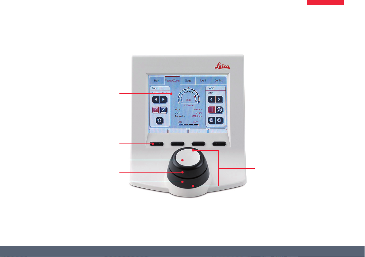
An Overview of the Leica SmartTouch™
Touchscreen
Hardware keys (freely congurable)
Toggle button
Top rotary actuator
Bottom rotary actuator
Double rotary actuator
Leica SmartTouch™ Manual 15
Page 16

Encoded and Unencoded Components
The Leica M series has various encoded
and motorized components; this means
that the current status of a component is automatically transmitted to the Leica SmartTouch™.
These data are displayed on the control panel
and included in various calculations. At the
same time, it is possible to control motorized
components remotely via the Leica SmartTouch™.
Encoded components
For example, if you adjust the encoded iris
diaphragm on a Leica M205 C using the dial,
the size of the aperture is automatically transmitted to the Leica SmartTouch™. The transmitted value is then used to calculate and display
the depth of eld, for example.
For some instruments, such as the Leica M205
A, this also works the other way around: the iris
diaphragm can be opened and closed by input
on the Leica SmartTouch™.
Unencoded components
Not all components of the M series are encoded.
The objectives, spacer rings and eyepieces are
among the unencoded elements.
To ensure that these unencoded elements are
included in the various calculations correctly,
a one-time conguration of these elements is
required. For instructions, refer to page 24.
If an unencoded component is replaced
with another component, this component must be detected correctly – otherwise,
the Leica SmartTouch™ will show incorrect
values on the display.
Leica SmartTouch™ Manual 16
Page 17

Leica SmartTouch™ and Leica Application Suite (LAS)
The Leica SmartTouch™ can control
the entire microscope conguration. In
many cases, there are additional options when
the Leica SmartTouch™ is used in conjunction
with the Leica Application Suite (LAS) PC software.
Advanced options
By interacting with LAS, the Leica SmartTouch™
can supplement the PC-based control system in
the following areas:
Ϙ Controlling the camera via Leica Smart-
Touch™.
Ϙ Synchronizing the settings (for example,
hardware setups or key assignments)
between the Leica SmartTouch™ and LAS.
Ϙ Displaying the stage position when using
LAS PowerMosaic.
Leica SmartTouch™ Manual 17
Page 18

Controls on the Touchscreen
Tab
Display
Button
Display of the current function
of a hardware key
Segment
Scroll bar arrows
Display conventions
The display on the display panel only
shows the conguration that is actually
present. For example, if the motorized mechanical stage is not connected, the corresponding
settings are not displayed. The screenshots in
this manual may thus dier from the display on
your Leica SmartTouch™.
Color coding conventions
All xed elements of the user interface
(such as labels or titles) are displayed in
a black font. All the values that can be modied
(such as the zoom factor, status of the illuminator, etc.) are displayed in a red font.
Leica SmartTouch™ Manual 18
Page 19

Calling up the Main view
The "Main" view allows you to see at a
glance which components can be controlled via the Leica SmartTouch™. The current
values and positions of connected instruments
are also displayed. These include, for example,
the aperture of the iris diaphragm, the position of the motorized mechanical stage, the
currently used lters and more.
In the Main view screen, settings cannot
be modied. However, the stored congurations can still be called up (see page 63).
Calling up the Main view
1. Touch the "Main" tab to display the current
values.
2. Touch the "Focus/Zoom", "Stage" or "Light"
tabs to modify the settings for the respective instruments.
Calling up a stored conguration
1. Touch the desired hardware key to call up a
dierent conguration.
Leica SmartTouch™ Manual 19
Page 20

The "Main" View
Only instruments that are actually connected are
displayed.
1. Total visual magnication
2. Position within possible magnication
3. Motorized focus position within positioning range
4. Aperture of the iris diaphragm in values between 20%
(closed) and 100% (completely open)
5. Current position of motorized mechanical stage
6. Filter used and status of the shutter for uorescence
equipment conguration
7. Status of the shutter for the
Leica "TL RCI" transmitted light base
8. Status of Leica "LED5000 MCI" illuminator
9. Status of Leica "LED5000 RL-80/48" illuminator
3
2
1
4
5
6
7
8
9
Leica SmartTouch™ Manual 20
Page 21

Setup and Conguration
Leica SmartTouch™ Manual 21
Page 22

Selecting the Desired Language
The user interface of the Leica Smart-
Touch™ is displayed in English by default.
In addition, the following languages are available:
Ϙ German
Ϙ French
Ϙ Italian
Ϙ Spanish
Ϙ Chinese
Ϙ Japanese
Changing the language
1. Touch the "Cong." tab.
2. Touch the button for the SmartTouch™
settings.
3. Touch the button for language selection.
4. Touch the desired language.
The selected language is used immedi-
ately. Restarting the instrument is not
required.
Leica SmartTouch™ Manual 22
Page 23

The "Cong." Tab
The "Cong." tab contains all the
commands and settings so that the Leica
SmartTouch™ can be better adapted to your
needs and requirements. This includes settings
you can adjust at your discretion, for example,
switching the key tone on or o or adjusting
the brightness of the display. Other settings,
however, are indispensable, for example, detecting unencoded components (refer also to page
16).
Any changes to the settings are carried
out immediately and stored.
Calling up the settings
1. Touch the "Cong." tab.
2. Select the desired category in the "Cong."
eld.
3. Congure the settings in the right eld.
Leica SmartTouch™ Manual 23
Page 24
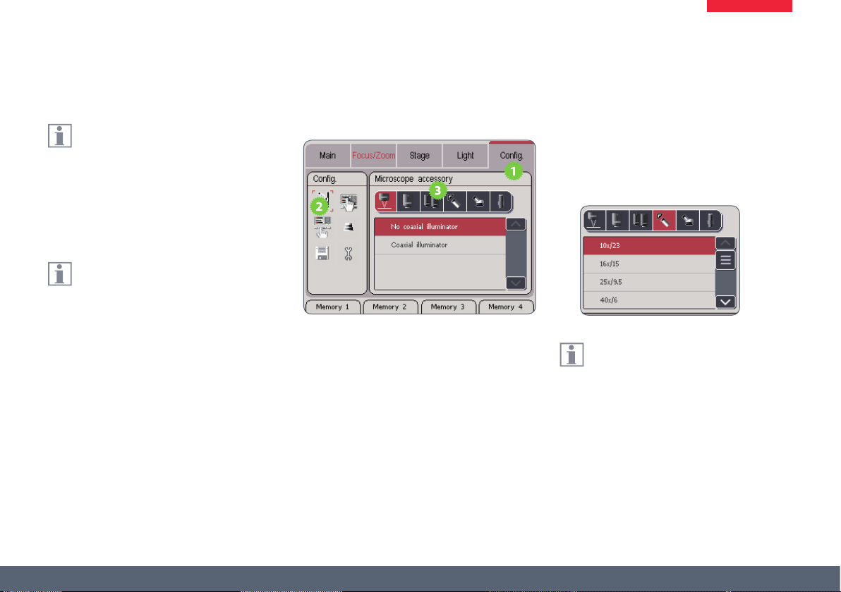
Conguration of Unencoded Components
Unencoded components (such as an
objective) are not detected automatically by the Leica SmartTouch™. To ensure that
these components are included in the various
calculations (depth of eld, zoom factor, etc.)
correctly, they must be congured in the Leica
SmartTouch™.
These congurations must be carried out
on the following occasions:
Ϙ Initial commissioning of the microscope.
Ϙ After an unencoded component has been
replaced by a component with dierent
properties.
Ϙ After the Leica SmartTouch™ has been reset
to the factory defaults.
Registering components
1. Touch the "Cong." tab.
2. In the left area, touch the symbol for the
microscope accessories.
3. Touch the symbol of the instrument component that you would like to detect.
4. In the list with the available components,
touch the components you are using.
5. Repeat steps 3 and 4 for all components
that you would like to use.
Each change is stored immediately.
Restarting the instrument is not required.
Leica SmartTouch™ Manual 24
Page 25

Conguration of the Objective Nosepiece
The encoded objective nosepiece holds
two objectives or FluoCombi™ so that
they can be exchanged by simply turning
them.
Preparations
1. Install the encoded objective nosepiece and
the two objectives on the optics carrier.
Registering the rst objective
1. On the Leica SmartTouch™, touch the
"Cong." tab.
2. In the left area, touch the symbol for the
microscope accessories.
3. Rotate the rst objective so it is in the beam
path of the microscope carrier.
4. Touch the symbol for detecting the rst
objective.
5. Touch the type of objective that is in the
beam path.
(Continued on next page)
Leica SmartTouch™ Manual 25
Page 26

Registering the objective nosepiece (cont'd)
Detecting the second objective
1. Rotate the second objective so it is in the
beam path of the microscope carrier.
2. Touch the symbol for detecting the second
objective.
3. Touch the type of objective that is in the
beam path.
From this point forward, the Leica Smart-
Touch™ knows which objective is in the
beam path and can subsequently calculate the
magnication, depth of eld and other values
correctly.
Leica SmartTouch™ Manual 26
Page 27

Resetting to Factory Defaults
When the Leica SmartTouch™ is reset to
the factory defaults, all values are reset
without exception. However, a stereomicroscope with uorescence equipment conguration will have dierent factory defaults than a
macroscope.
The label of the button for the factory
defaults depends on the connected
microscope.
When the button for factory defaults is
touched, the Leica SmartTouch™ is reset
immediately without further warning. This
command cannot be undone.
Resetting to Factory Defaults
1. Touch the "Cong." tab.
2. Touch the button for the SmartTouch™
settings.
3. Touch the button for the factory defaults.
4. Touch the button for resetting to the factory
defaults.
Leica SmartTouch™ Manual 27
Page 28
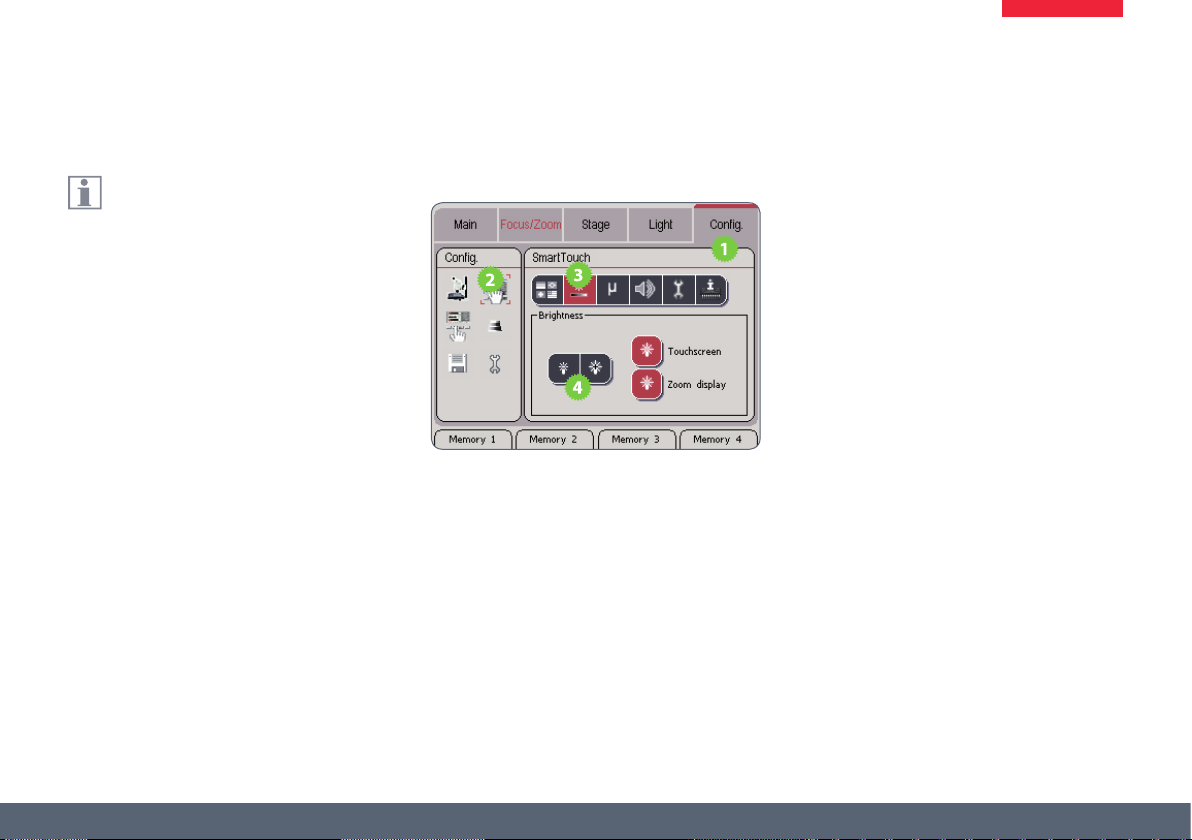
Adjusting the Brightness of the Display
In critical applications (such as uores-
cence microscopy), the backlighting of
a display can produce unwanted ambient light.
Therefore, it can be attenuated or even switched
o entirely – both on the Leica SmartTouch™
itself and on the Leica M205 A and M205 FA
stereomicroscopes.
Adjusting the display brightness
1. Touch the "Cong." tab.
2. Touch the button for the SmartTouch™
settings.
3. Touch the button for the display brightness.
4. Touch the symbols for the brightness multiple times to adjust the display illumination on the Leica SmartTouch™ and on the
stereomicroscope.
(Continued on next page)
Leica SmartTouch™ Manual 28
Page 29

Adjusting the Display Brightness (cont'd)
Switching the backlighting of the Leica
SmartTouch™ on and o
1. Touch the symbol next to the "Touchscreen"
title to switch o the backlighting on the
Leica SmartTouch™.
2. Touch any desired location on the touchscreen to switch the backlighting back on.
Switching the microscope display on and
o
1. Touch the symbol next to the "Zoom
display" title to switch o the backlighting
of the microscope display.
2. Touch the symbol a second time to switch
the backlighting back on.
Leica SmartTouch™ Manual 29
Page 30
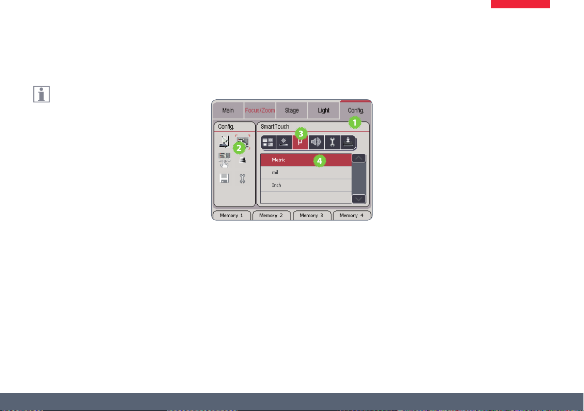
Changing the Units of Measure
To specify distance, you can use the units
of measure "Metric" (millimeter), "mil"
(1/10 inch) and "Inch" (1 inch = 2.54 cm) on the
Leica SmartTouch™.
Selecting the unit of measure
1. Touch the "Cong." tab.
2. Touch the button for the SmartTouch™
settings.
3. Touch the button for the units of measure.
4. Touch the desired unit of measure.
Leica SmartTouch™ Manual 30
Page 31

Switching the signal tone on and o
The Leica SmartTouch™ conrms each
touch of the display and each turn of the
double rotary actuator with a signal tone. This
signal tone can be switched o if necessary.
Switching the signal tone on and o
1. Touch the "Cong." tab.
2. Touch the button for the SmartTouch™
settings.
3. Touch the button for the signal tones.
4. Touch the desired symbol to switch the
signal tones o and on again.
Leica SmartTouch™ Manual 31
Page 32

Calibrating the touchscreen
The touchscreen of the Leica Smart-
Touch™ must be calibrated whenever
touching a button triggers the wrong function
or none at all.
Calibrating the touchscreen
1. Touch the "Cong." tab.
2. Touch the button for the SmartTouch™
settings.
3. Touch the button for the hardware conguration.
4. Touch the "Panel calibration" button to
start the calibration of the touchscreen.
5. Follow the instructions on the touchscreen.
Leica SmartTouch™ Manual 32
Page 33

Calibrating the zoom
Every Leica instrument and accessory
is built and inspected according to the
most stringent criteria. In most cases, the preinstalled conguration should meet your needs.
However, if you want to use the Leica SmartTouch™ to measure as accurately as possible,
you can calibrate the zoom. This compensates
for the already tiny manufacturing tolerances.
For the calibration, the optional graticule
10 450 054 and a stage micrometer are
required.
Preparations
1. Insert the graticule into the eyepiece.
2. Place the stage micrometer under the
microscope.
3. Adjust the instrument to the magnication
you want to calibrate (for example 50×).
The calibration improves accuracy over
the entire zoom range. However, you will
obtain the most accurate results at the magnication you have selected for the calibration.
(Continued on next page)
Leica SmartTouch™ Manual 33
Page 34

Calibrating the Zoom (cont'd)
Calibrating the zoom
1. Touch the "Cong." tab.
2. Touch the button for the calibration.
3. Touch the "Calibrate" button.
4. Touch the "Start" button.
5. Look through the eyepieces and zoom
using the rotary actuators until you have
brought the graticule and stage micrometer into alignment.
6. Touch the "Save" button.
For example, if you want to calibrate the 50 x
magnication and the stage micrometer is
divided into units of 0.1 mm, you have to
bring 5 mm into alignment.
Leica SmartTouch™ Manual 34
Page 35
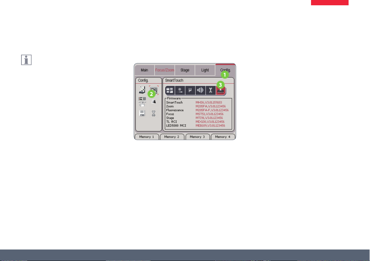
Checking the Firmware Version
The Leica SmartTouch™ shows both its
own rmware version as well as that of
all connected motorized and encoded instruments.
Checking the rmware
1. Touch the "Cong." tab.
2. Touch the button for the SmartTouch™
settings.
3. Touch the button for displaying the rmware.
Leica SmartTouch™ Manual 35
Page 36

The "Focus/Zoom" Tab
Leica SmartTouch™ Manual 36
Page 37
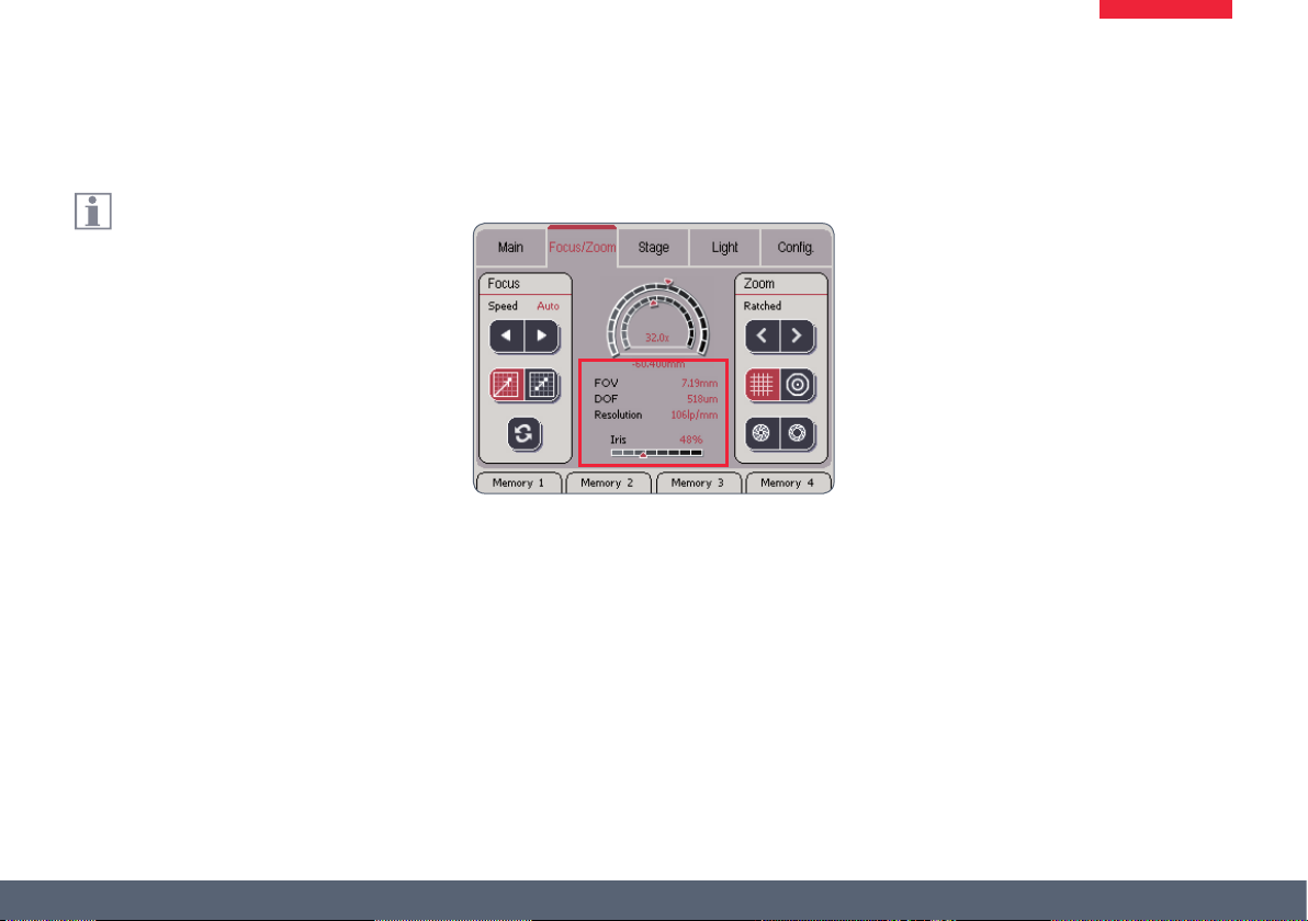
Information about the Displays
The changes to the zoom are shown in
the middle area of the display.
Meaning of the abbreviations FOV = Field Of View
The eld of view shows the diameter of the
cutout in the object eld that is visible in the
eyepiece.
DOF = Depth Of Field
The depth of eld refers to the vertical area
displayed in sharp focus in the eyepiece.
Resolution
The resolution of the current setting is specied
in "lp/mm" (line pairs per millimeter). This resolution varies with the optical magnication and
the aperture of the iris diaphragm.
Leica SmartTouch™ Manual 37
Page 38
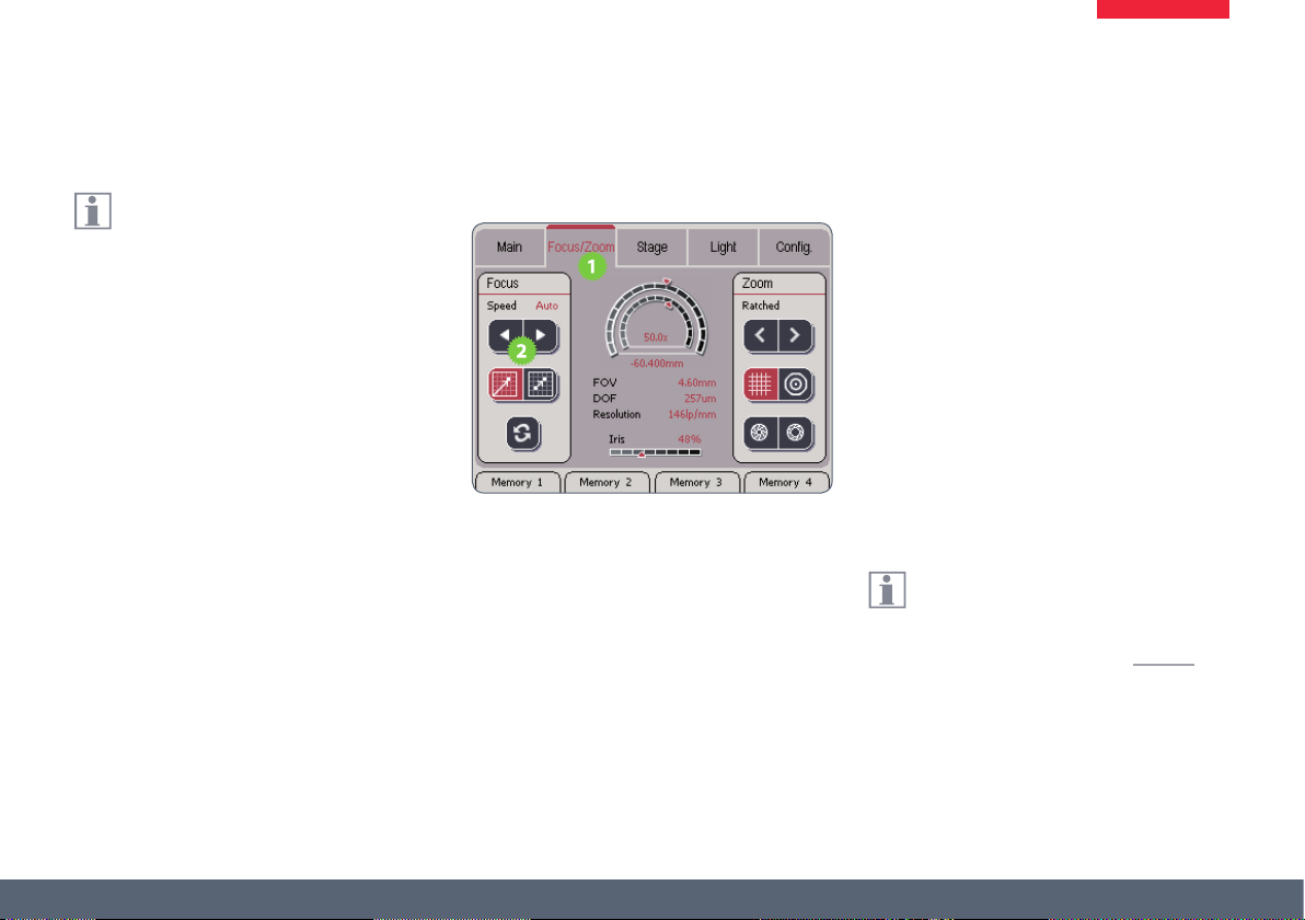
Focus Settings
The settings in the "Focus" area enable
you to adapt the behavior of the motor-
ized focus to your wishes and requirements.
Changing the speed of focusing
1. Touch the "Focus/Zoom" tab.
2. Touch the "Speed" buttons to change the
setting between "Slow", "Fast" and "Auto".
Ϙ The "Slow" setting changes the focus only
slowly. It is particularly suitable if you
usually work at a high magnication.
Ϙ The "Fast" setting changes the focus more
quickly. It is suitable if you usually work at a
low magnication.
Ϙ The "Auto" setting adapts the speed to the
respective magnication. It is particularly
suitable if you have to change magnication frequently. Note that: High magnication level = slow focus – Low magnication
level = fast focus.
(Continued on next page)
Before the Leica SmartTouch™ can
measure the distance between the
current and top position, you have to calibrate
the focus. For instructions, refer to page 33.
Leica SmartTouch™ Manual 38
Page 39

Focus Settings (cont'd.)
Changing the reference coordinates
1. Touch the "Absolute reference point"
symbol. The display shows the distance
between the current position and the
uppermost position that can be assumed
by the motorized focus.
2. Touch the "Relative reference point"
symbol. The display shows the distance
between the current position and the zero
point dened by the user.
(Continued on next page)
Manually dening the zero point
To measure the distance between two motorized focus positions, proceed as follows:
1. Move the motorized focus into the position
that is to be the zero point.
Leica SmartTouch™ Manual 39
Page 40
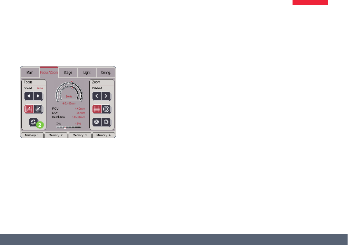
Focus Settings (cont'd.)
2. Touch the button with the double arrow to
dene this position as the zero point.
3. Move the motorized focus into the new
position. The display now shows the
distance to the manually set zero point.
Leica SmartTouch™ Manual 40
Page 41

Zoom Settings
In the "Zoom" area, you can congure the
settings for the ratchet stop, measure-
ment and the iris diaphragm.
Ratchet
1. The zoom position is controlled using the
"Ratchet" buttons. This changes the zoom
in predened increments ("ratchet stops").
This behavior corresponds to the ratchet
stops of manual microscopes.
Switching between measurement and eld
of view
1. Touch the grid key to reach the display of
the optical resolution.
(Continued on next page)
Leica SmartTouch™ Manual 41
Page 42
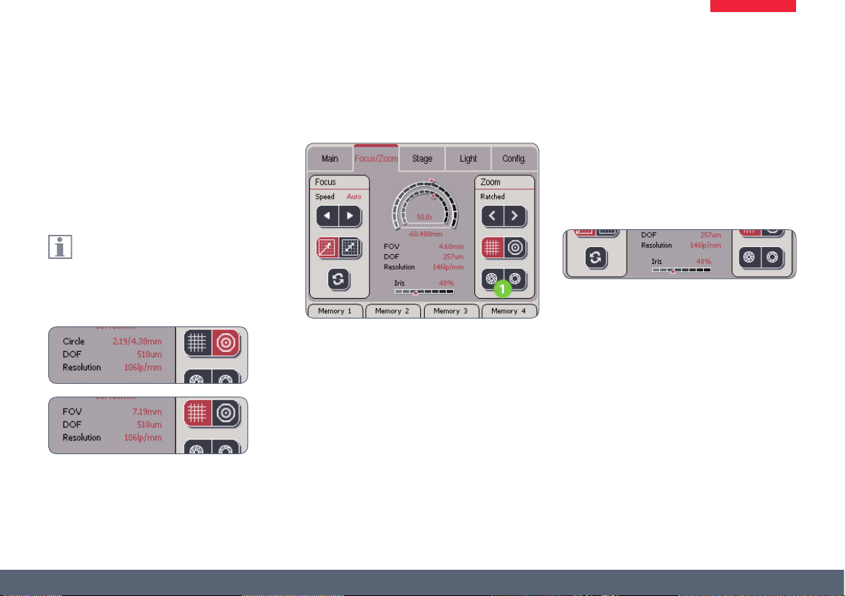
Zoom Settings (cont'd.)
2. Touch the circle key to use the area covered
by the optional graticule (Art. No. 10450054)
for the measurement. Use this measuring
method only if your microscope is equipped
with this graticule in the eyepiece.
The eects of the selected measur-
ing method are shown directly in the
display.
Iris diaphragm control
1. Use the iris diaphragm control keys to open
and close the iris diaphragm. The eects
on the depth of eld are shown on the
Leica SmartTouch™ under "DOF" (Depth Of
Field).
Leica SmartTouch™ Manual 42
Page 43

Measuring with the graticule
Using the optional graticule (Art. No.
10450054), you can carry out simple
measurements directly using the Leica SmartTouch™.
Measuring with the graticule
1. Insert the graticule into the eyepiece.
2. On the Leica SmartTouch™, touch the
"Focus/Zoom" tab.
3. Touch the symbol for the circular graticule.
4. Zoom in on the specimen to be measured
so that it lls in the small or large circle on
the graticule as accurately as possible.
5. Read the measured value on the Leica
SmartTouch™. The Leica SmartTouch™
shows you the measurement results of the
larger (left) and the smaller circle simultaneously. The values correspond to the radii
in the specimen plane.
Leica SmartTouch™ Manual 43
Page 44

Moving the Rotary Head
Using the Leica SmartTouch™, you
can bring the rotary head on the Leica
DVM5000 into the desired position.
Moving the rotary head
1. On the Leica SmartTouch™, touch the
"Focus/Zoom" tab.
2. Touch the upper arrow buttons to dene
the speed of rotation.
3. Click the lower arrow keys to rotate the
rotary head.
Leica SmartTouch™ Manual 44
Page 45

The "Stage" Tab
Leica SmartTouch™ Manual 45
Page 46
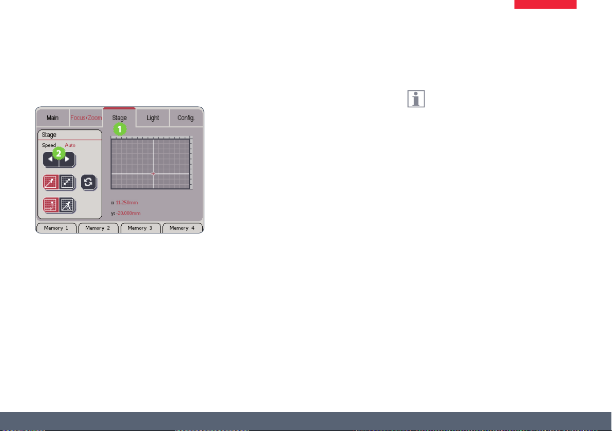
Modifying the travel path speed
Modifying the Travel Path Speed
1. Touch the "Stage" tab to call up the settings
for the motorized mechanical stage.
2. Touch the "Speed" buttons to change the
setting between "Slow", "Fast" and "Auto".
Ϙ The "Slow" setting moves the stage only
slowly. It is particularly suitable if you
usually work at a high magnication.
Ϙ The "Fast" setting moves the stage more
quickly. It is particularly suitable if you are
working at a low magnication or want to
move to a distant specimen quickly.
Ϙ The "Auto" setting adapts the speed to
the respective magnication. It is particularly suitable if you change magnication
frequently. Note that: High magnication
level = slow movement – Low magnication level = fast movement.
The stage surface can also be moved
using the double rotary actuator.
Leica SmartTouch™ Manual 46
Page 47
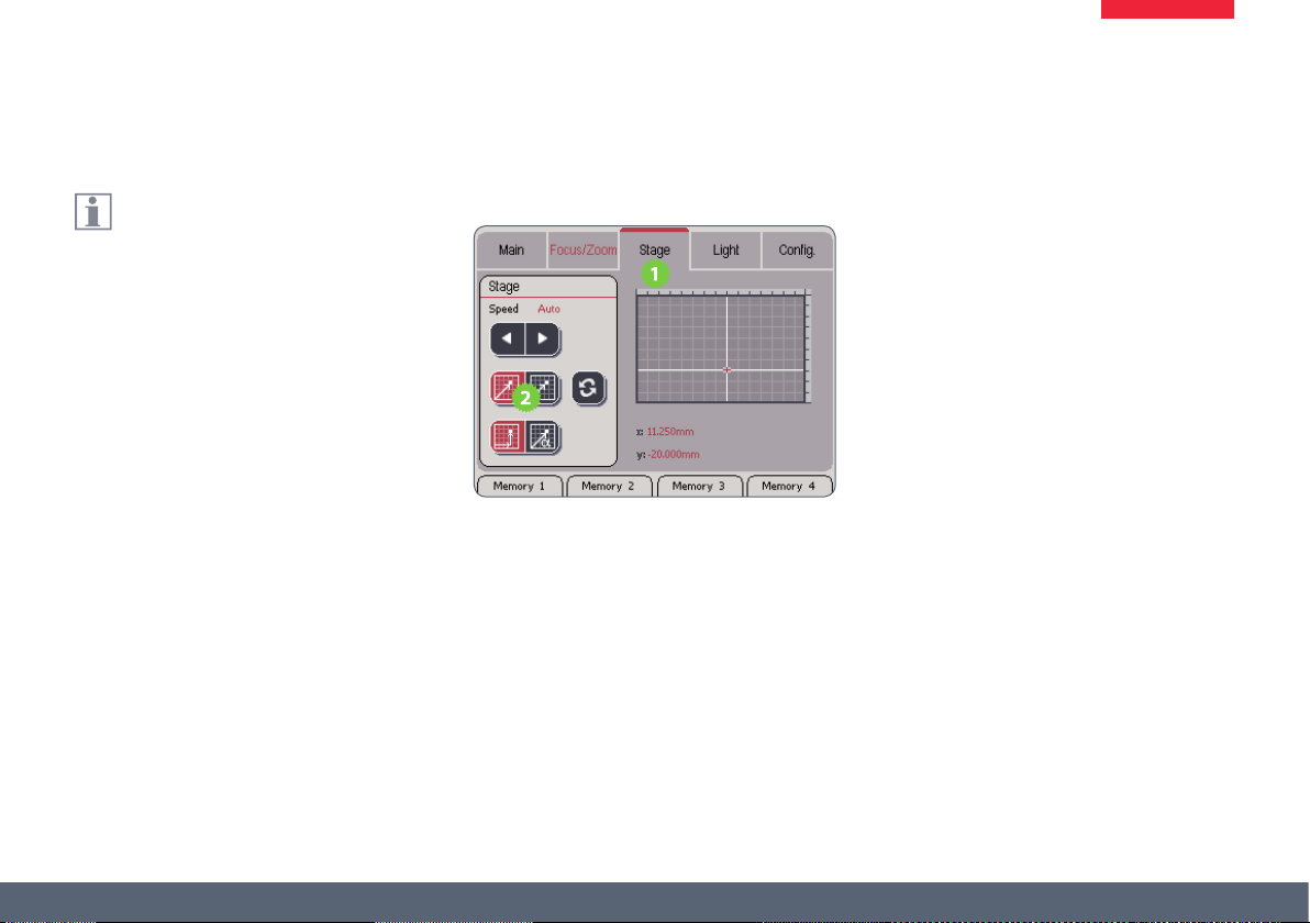
Changing the Reference Coordinates
The coordinates of the motorized
mechanical stage are based either on the
bottom left corner of the stage or a zero point
dened by the user.
Changing the reference coordinates
1. Touch the "Stage" tab.
2. Touch the desired measurement method:
Ϙ Absolute reference point (left symbol):
Shows the distance between the bottom
left corner and the current position.
Ϙ Relative reference point (right symbol):
Shows the distance between the current
position and the zero point dened by the
user.
(Continued on next page)
Leica SmartTouch™ Manual 47
Page 48

Changing the Reference Coordinates (cont'd)
Manually dening the zero point
To measure the distance between two positions, proceed as follows:
1. Move the "IsoPro" motorized mechanical
stage into the position that is to be the zero
point.
2. Touch the button with the double arrow to
dene this position as the zero point.
3. Move the mechanical stage into the new
position. The display now shows the
distance to the manually set zero point.
Leica SmartTouch™ Manual 48
Page 49
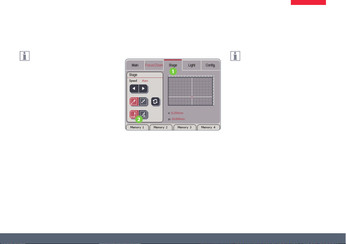
Changing the Coordinate System
You can toggle the coordinate system
between the Cartesian coordinate system
and the polar view.
Changing the coordinate system
1. Touch the "Stage" tab.
2. In the "Stage" area, touch the desired coordinate system:
Ϙ Cartesian coordinates (left symbol): Shows
the distance between the bottom left
corner and the current position based on
the X/Y-axes.
Ϙ Polar coordinates (right symbol): Displays
the distance based on the radius and
angle.
The display as polar coordinates can also
be used for simple distance measure-
ments.
Leica SmartTouch™ Manual 49
Page 50

Measuring via polar coordinates
You can also carry out simple distance
measurements using the polar view.
Measuring via polar coordinates
1. Switch the display to polar coordinates.
2. Move the Leica "IsoPro" motorized mechanical stage to the rst measurement position.
3. Set the reference point to "Zero" by touching the button with the double arrow.
4. Move the motorized mechanical stage to
the second measurement position.
You can now read the traveled distance on the
Leica SmartTouch™ under "Radius".
Leica SmartTouch™ Manual 50
Page 51

The "Light" Tab
Leica SmartTouch™ Manual 51
Page 52

Selecting the light source
Depending on the selected light source,
the lower area of the display changes
accordingly.
Only those light sources that are actually
connected are displayed.
Selecting the light source
1. Touch the "Light" tab.
2. Touch the desired light source in the upper
area.
Symbols for light sources
2
1
5
1. Fluorescence illumination
2. Transmitted Light Base RCI
3. LED5000 MCI
4. LED5000 RL-80/48
5. LED5000 CXI
6. LED3000 RL
7. LED3000 NVI
8. LED5000 HDI
3 4
6
7 8
Leica SmartTouch™ Manual 52
Page 53
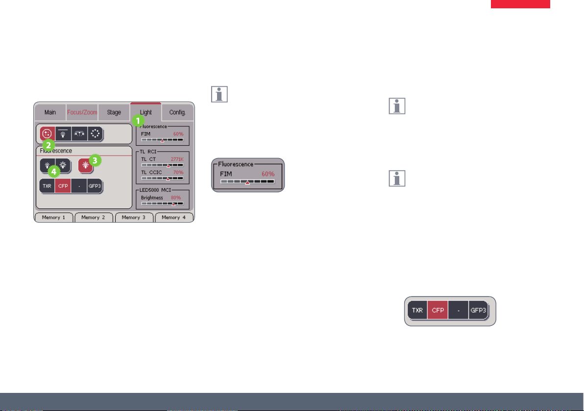
Control of the Leica Fluorescence Illumination
Adjusting the illumination
1. Touch the "Light" tab.
2. In the upper area, touch the symbol of the
uorescence light source.
3. Touch the symbol of the uorescence shutter to open the shutter.
4. Adjust the brightness.
The brightness is controlled by the FIM
(Fluorescence Intensity Manager). This is
a diaphragm that controls the quantity of light.
The aperture of the FIM is displayed on the
Leica SmartTouch™.
Changing the lter
The illuminator and the lter wheel can
be controlled using the Leica SmartTouch™. The lters are encoded so that the label
always corresponds to the actual inserted lter.
An empty lter insert is indicated by a line ( - ).
When using a Leica M165 FC stereomicro-
scope, you cannot change the lter and
shutter using the Leica SmartTouch™. However,
the type and position of the lter is detected
and displayed on the Leica SmartTouch™.
1. Touch the desired lter to swing it into the
beam path.
Leica SmartTouch™ Manual 53
Page 54
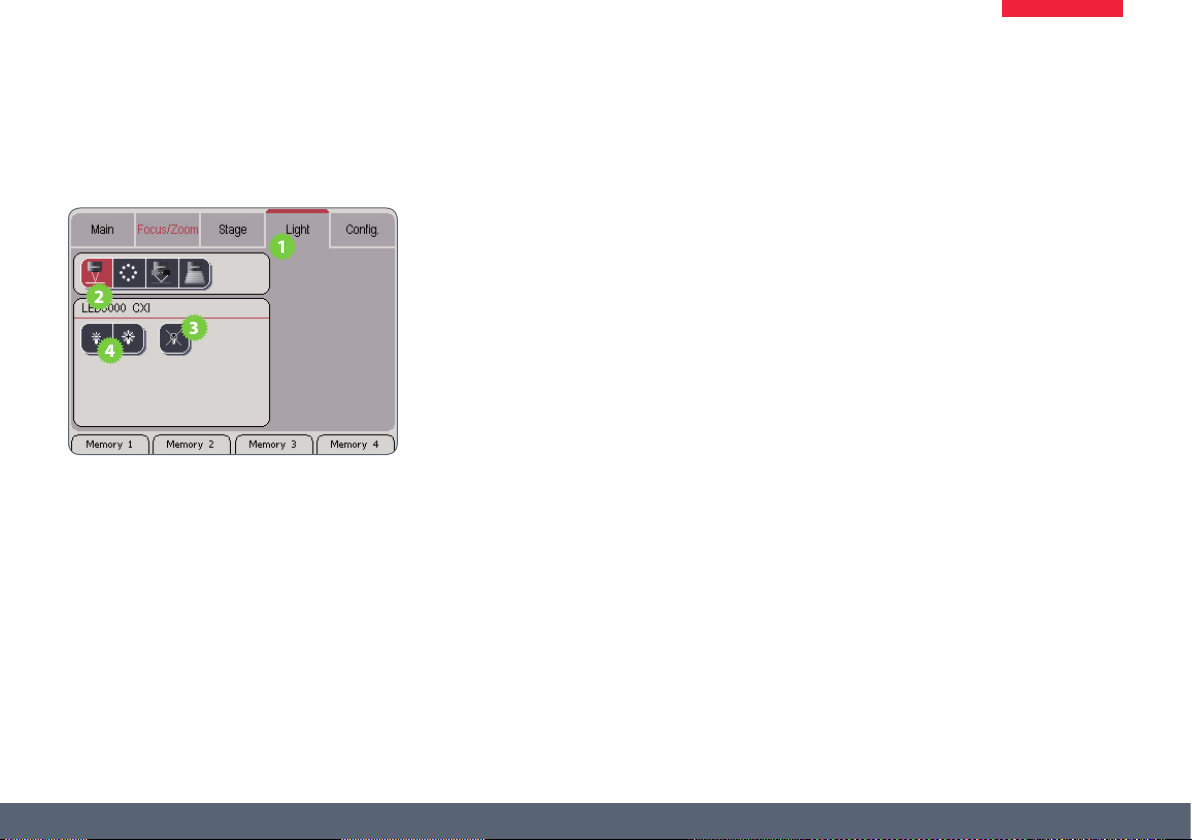
Control of the Leica LED5000 CXI
Adjusting the illumination
1. Touch the "Light" tab.
2. In the upper area, touch the symbol of the
Leica LED5000 CXI.
3. Switch on the illuminator.
4. Touch the lamp symbols to adjust the intensity of the light.
Leica SmartTouch™ Manual 54
Page 55

Control of the Leica LED3000 NVI
Adjusting the illumination
1. Touch the "Light" tab.
2. In the upper area, touch the symbol of the
Leica LED3000 NVI.
3. Switch on the illuminator.
4. Touch the lamp symbols to adjust the intensity of the light.
Leica SmartTouch™ Manual 55
Page 56
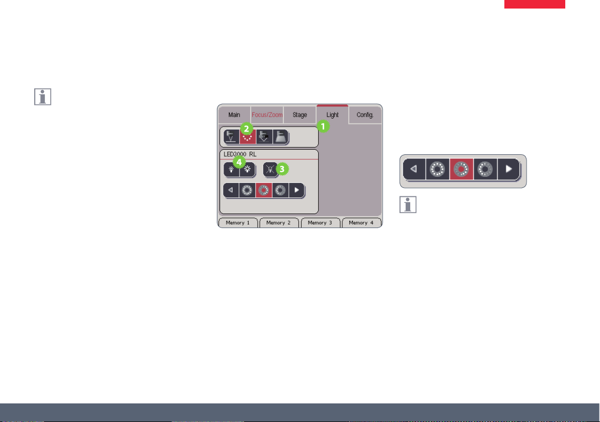
Control of the Leica LED5000 3000 Ring Illuminator
Using the Leica SmartTouch™, you can
control both the brightness and various
illumination scenarios for the Leica LED3000 RL
("Ring Light").
Adjusting the illumination
1. Touch the "Light" tab.
2. In the upper area, touch the symbol for the
Leica LED3000 RL.
3. Switch on the illuminator.
4. Touch the lamp symbols to adjust the intensity of the light.
5. Touch one of the symbols for the light
scenarios to adjust the lighting to your
needs.
You cannot modify the default illumina-
tion scenarios.
Leica SmartTouch™ Manual 56
Page 57
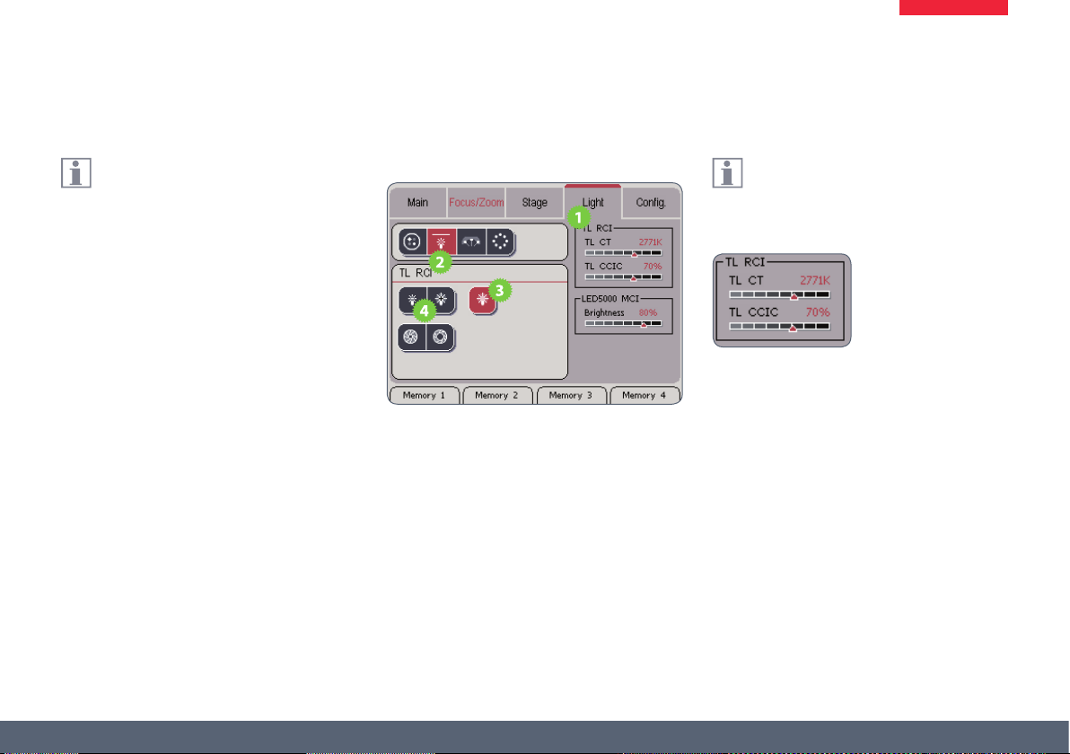
Control of the Leica TL RCI Transmitted Light Base
The quantity of light for the Leica "TL RCI"
transmitted light base can be adjusted in
two ways.
Ϙ If the brightness is controlled via the light
intensity, the color temperature changes
along with the brightness.
Ϙ If the brightness is controlled via the
mechanical diaphragm, the color temperature remains constant. When using a Leica
digital camera, no additional white balance
is necessary.
Adjusting the illumination
1. Touch the "Light" tab.
2. In the upper area, touch the symbol of the
transmitted light base.
3. Switch on the illuminator.
4. Touch the lamp symbols to adjust the intensity of the light.
The color temperature changes along
with the brightness. The current color
temperature is displayed on the Leica SmartTouch™.
(Continued on next page)
Leica SmartTouch™ Manual 57
Page 58

Control of the Leica TL RCI Transmitted Light Base (cont'd)
Changing the quantity of light
1. Switch on the illuminator.
2. Touch the symbols with the iris to adjust
the brightness via the diaphragm aperture.
The color temperature remains constant
at any brightness. The size of the
diaphragm aperture is displayed on the Leica
SmartTouch™ under "TL CCIC" ("Constant Color
Intensity Control").
Leica SmartTouch™ Manual 58
Page 59

Control of the Leica LED5000 MCI
Using the Leica SmartTouch™, you can
control both the brightness and various
illumination scenarios for the Leica LED5000
MCI ("Multi Contrast Illumination").
Adjusting the illumination
1. Touch the "Light" tab.
2. In the upper area, touch the symbol for the
Leica LED5000 MCI.
3. Switch on the illuminator.
4. Touch the lamp symbols to adjust the intensity of the light.
The selected brightness is shown on the
right side of the display.
5. Touch one of the symbols for the light
scenarios to adjust the lighting to your
needs.
You cannot modify the default illumina-
tion scenarios.
Leica SmartTouch™ Manual 59
Page 60
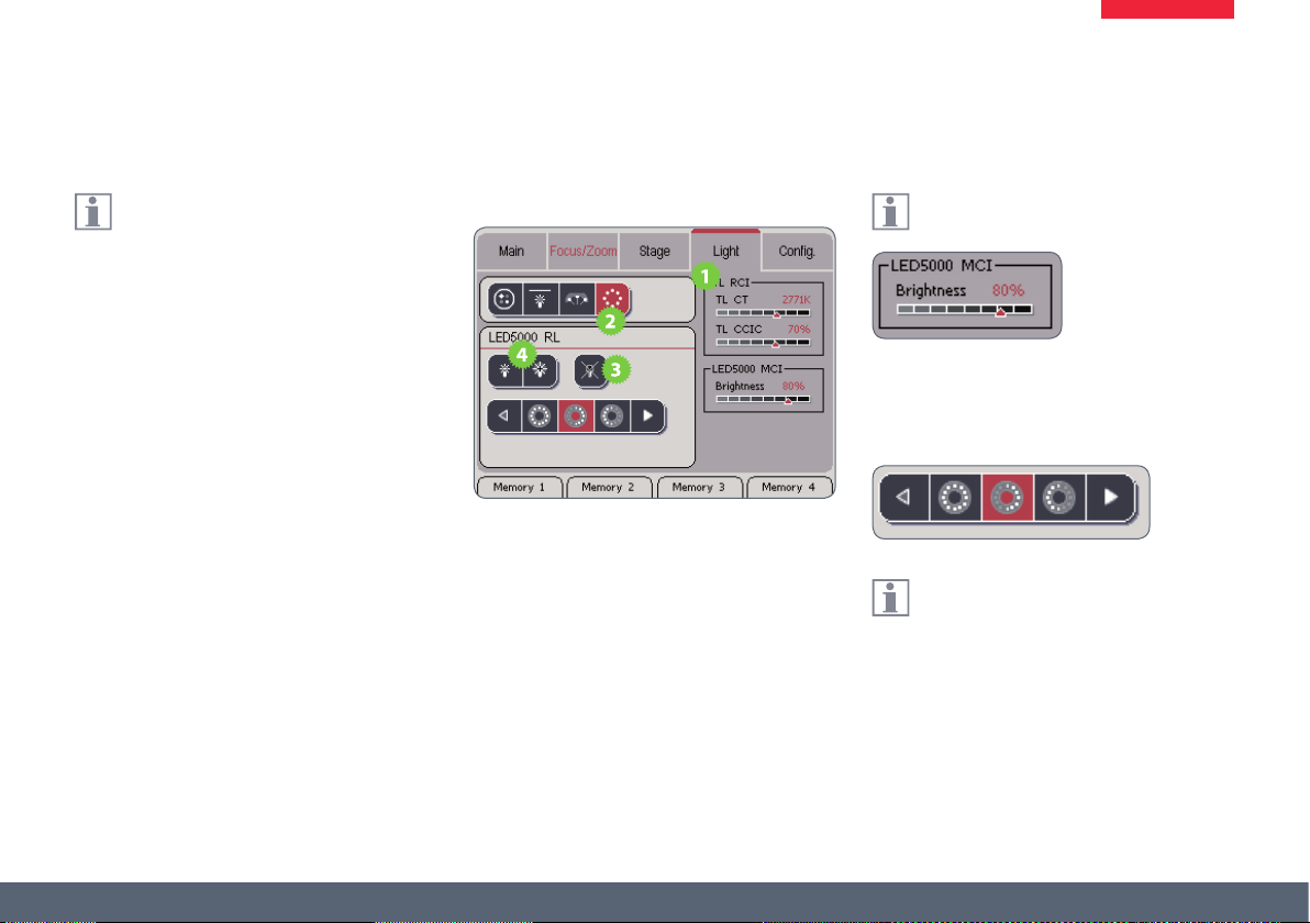
Control of the Leica LED5000 RL-80/48 Ring Illuminator
Using the Leica SmartTouch™, you can
control both the brightness and various
illumination scenarios for the Leica LED5000 RL
("Ring Light").
Adjusting the illumination
1. Touch the "Light" tab.
2. In the upper area, touch the symbol for the
Leica LED5000 RL.
3. Switch on the illuminator.
4. Touch the lamp symbols to adjust the intensity of the light.
The selected brightness is shown on the
right side of the display.
5. Touch one of the symbols for the light
scenarios to adjust the lighting to your
needs.
You cannot modify the default illumina-
tion scenarios.
Leica SmartTouch™ Manual 60
Page 61
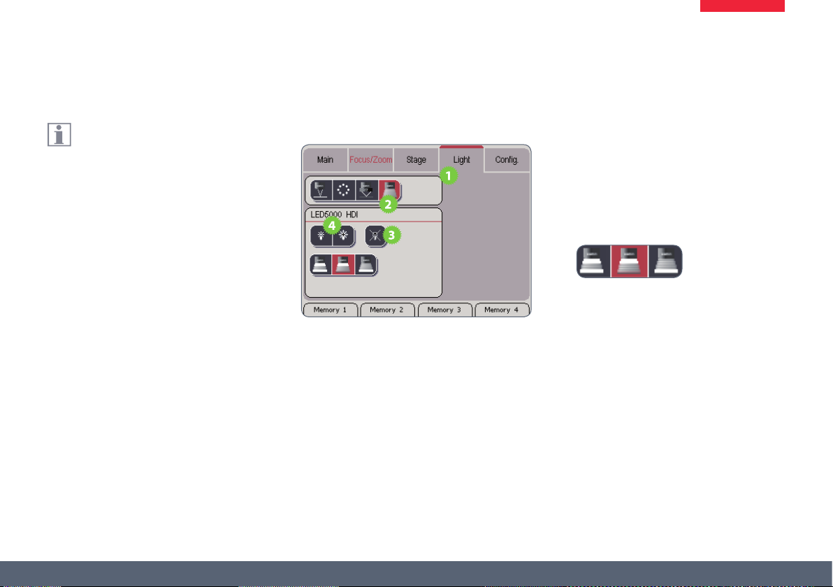
Control of the Leica LED5000 HDI
Using the Leica SmartTouch™, you can
control both the brightness and the various illumination scenarios for the Leica LED5000
RL ("Ring Light").
Adjusting the illumination
1. Touch the "Light" tab.
2. In the upper area, touch the symbol for the
Leica LED5000 HDI.
3. Switch on the illuminator.
4. Touch the lamp symbols to adjust the intensity of the light.
5. Touch one of the symbols for the light
settings to adjust the lighting to your
needs.
Leica SmartTouch™ Manual 61
Page 62

Memory Key Assignment
Leica SmartTouch™ Manual 62
Page 63

Information about the Memory Keys
The Leica SmartTouch™ has four hard-
ware keys that can be assigned almost
any function. The assigned function is displayed
on the bottom edge of the touchscreen.
Functional display
Corresponding
hardware key
Leica SmartTouch™ Manual 63
Page 64

Assigning Memory Keys
Each of the four keys can be assigned
any desired function of the Leica SmartTouch™.
Assigning a Memory key
1. Touch the "Cong." tab.
2. Touch the button for the memory key
assignment.
3. Touch the desired memory location (1 to
4).
4. Touch an instrument or category to view
the possible commands.
5. Touch the command you want to assign to
the selected button.
(Continued on next page)
Leica SmartTouch™ Manual 64
Page 65

Assigning Memory Keys (cont'd)
The key on the bottom end of the touch-
screen changes its designation to indi-
cate the current assignment.
6. To congure the next memory key, touch
the desired memory location and repeat
steps 3 to 5.
Quick assignment of a Memory Key
If you want to congure Memory Key 2 without
having to use the menus, for example, proceed
as follows:
1. On the touchscreen, press the key you want
to assign for 3 seconds. The Leica SmartTouch™ goes automatically to the key
settings.
2. Assign the desired function to the key as
described.
Leica SmartTouch™ Manual 65
Page 66

Memory Key Commands List
Zoom
Zoom in Enlarges the view (zoom)
Zoom out Reduces the view (zoom)
Ratchet + Switches to the next ratchet stop position
Ratchet - Switches to the previous ratchet stop position
Open iris Opens the iris (= smaller depth of eld, but more light)
Close iris Closes the iris (= greater depth of eld, but less light)
Focus
Focus up Moves the focusing column upwards in larger increments
Focus down Moves the focusing column downwards in larger increments
Focus fast Switches the focusing speed to "Fast"
Focus autom. Switches the focusing speed to "Auto"
Focus slow Switches the focusing speed to "Slow"
Focus abs./rel. Changes the focus display between "absolute" and "relative"
Focus ref. Sets the current focus position to the value "0"
Fine focus
Fine focus up Moves the focusing column upwards in small increments
Fine focus down Moves the focusing column downwards in small increments
Leica SmartTouch™ Manual 66
Page 67

Memory Key Commands List (cont'd)
X/Y stage
Stage X+ Moves the motorized mechanical stage towards the left
Stage X- Moves the motorized mechanical stage towards the right
Stage Y+ Moves the motorized mechanical stage towards the rear
Stage Y- Moves the motorized mechanical stage towards the front
Stage fast Switches the travel speed to "Fast"
Stage autom. Switches the travel speed to "Auto"
Stage slow Switches the travel speed to "Slow"
Stage abs./rel. Switches the coordinate display for the motorized mechanical stage between "absolute" and "relative"
Stage ref. Sets the current position of the motorized mechanical stage to the value "0"
Coord. stage Switches the coordinate display between the Cartesian and the polar display
LED5000 RL80/48
RL on/o Switches the LED5000 RL80/48 ring illuminator on and o
RL + Increases the brightness
RL - Decreases the brightness
RL #1-11 Scrolls through illumination scenarios 1 to 11
RL #1
…
RL #11
Activates illumination scenario 1 to 11 directly
Leica SmartTouch™ Manual 67
Page 68

Memory Key Commands List (cont'd)
LED5000 MCI
MCI on/o Switches the Leica LED5000 MCI Multi Contrast Illumination on and o
MCI + Increases the brightness
MCI - Decreases the brightness
MCI #1-5 Scrolls through illumination scenarios 1 to 5
MCI #1
…
MCI #5
CXI
CXI on/o Switches the Leica CXI coaxial illuminator on and o
CXI + Increases the brightness
CXI - Decreases the brightness
LED3000 NVI
NVI on/o Switches the Leica LED3000 NVI illuminator on and o
NVI + Increases the brightness
NVI - Decreases the brightness
Activates brightness scenario 1 to 5 directly
Leica SmartTouch™ Manual 68
Page 69

Memory Key Commands List (cont'd)
Transmitted light
TL shutter Switches the illuminator of the transmitted light base on and o
Toggle TL/FL Changes the status of the transmitted light and uorescence shutter
TL color temp + Increases the lamp voltage
TL color temp - Decreases the lamp voltage
TL brightness + Opens the CCIC diaphragm
TL brightness - Closes the CCIC diaphragm
Fluorescence
Filter 1
…
Filter 4
FL shutter Opens and closes the shutter of the uorescence illuminator
FIM + Increases the brightness by opening the FIM (Fluorescence Intensity Manager)
FIM - Reduces the brightness by closing the FIM
Filter left Replaces the current lter with the one to the left of it
Filter right Replaces the current lter with the one to the right of it
(Fluorescence) Rotates the lter wheel directly into lter position 1 to 4
Leica SmartTouch™ Manual 69
Page 70

Memory Key Commands List (cont'd)
Camera
Photo Takes a photograph using the connected Leica digital camera. (Leica Application Suite must be started for this purpose.)
Video
Memory
Memory + Memory positions are approached incrementally
Memory - Memory positions are approached decrementally
Memory 1 Memory position 1 is approached
Memory 2 Memory position 2 is approached
Memory 3 Memory position 3 is approached
Memory 4 Memory position 4 is approached
Memory 5 Memory position 5 is approached
Starts recording a lm sequence using the connected Leica digital camera. (For this purpose, the Leica Application Suite must
be loaded and the optional "Movie" expansion module must have been added.) To stop, press the button a second time.
Leica SmartTouch™ Manual 70
Page 71

Double Rotary Actuator Assignment
Leica SmartTouch™ Manual 71
Page 72

Information about the Double Rotary Actuator
The double rotary actuator consists
of two knobs, each of which can be
assigned two dierent functions. Thus a total
of four functions are available, which can be
assigned individually.
The toggle button is located at the top
end of the double rotary actuator. It is
used to toggle between the two assignments.
If the rotary actuators are not doubly assigned,
the toggle button can be assigned a function.
Bottom rotary actuator
Toggle button
Top rotary actuator
Double rotary actua-
tor
Leica SmartTouch™ Manual 72
Page 73

Assigning a Function to the Knobs
Each knob can be assigned two dierent
functions.
Assigning the rst function
1. Touch the "Cong." tab.
2. Touch the button for the double rotary
actuator assignment.
3. Touch one of these two symbols to select
the desired rotary actuator.
4. Touch the command you want to assign to
the selected rotary actuator.
(Continued on next page)
Leica SmartTouch™ Manual 73
Page 74

Assigning a Function to the Knobs (cont'd)
Assigning the second function
1. Touch one of the following two symbols to
select the desired rotary actuator.
2. Touch the command you want to assign to
the selected rotary actuator.
Toggling between the two assignments
1. Press the toggle button once briey to
switch from assignment 1 to assignment 2
(and vice versa).
Leica SmartTouch™ Manual 74
Page 75

Commands List: Rotary Knob
Name Function
Zoom Changes the magnication factor (zoom)
Iris Opens and closes the iris
Focus Controls the coarse focus
Fine focus Controls the ne focus
Stage X+ If the knob is moved clockwise, the motorized mechanical stage moves towards the left.
Stage Y+ If the knob is moved clockwise, the motorized mechanical stage moves towards the rear.
Stage X- If the knob is moved clockwise, the motorized mechanical stage moves towards the right.
Stage Y- If the knob is moved clockwise, the motorized mechanical stage moves towards the front.
TL CT Controls the brightness of the lamp in the transmitted light base
TL CCIC Controls the aperture of the shutter in the transmitted light base
FIM Controls the brightness of the uorescence illumination
LED5000 RL-80/48 Controls the brightness of the LED5000 RL-80/48 ring illuminator
LED5000 MCI Controls the brightness of the LED5000 MCI Multi Contrast Illumination
LED5000 CXI Controls the brightness of the coaxial illuminator
LED3000 NVI Controls the brightness of the LED5000 NVI (Near Vertical Illumination)
Leica SmartTouch™ Manual 75
Page 76
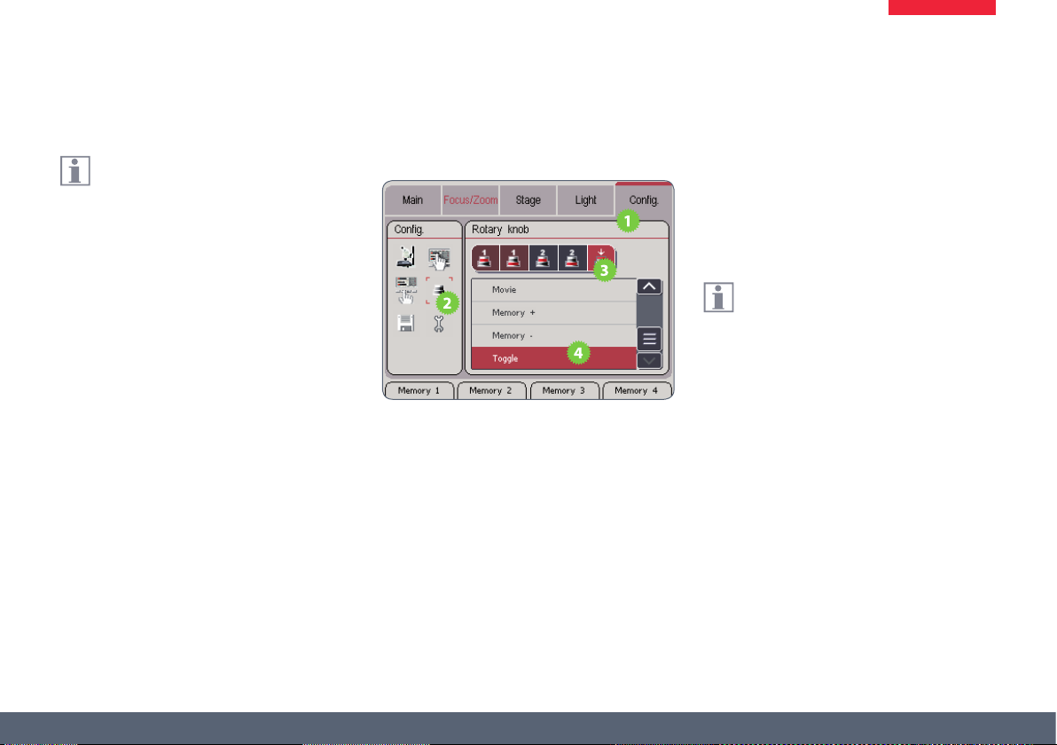
Assigning a Function to the Toggle Button
If you do not need the second level of
rotary actuators, you can assign the
toggle button on the double rotary actuator its
own function. Then, a total of three functions
are available to you:
Rotary actuator 1 + rotary actuator 2 + toggle
button
Assigning the toggle button
1. Touch the "Cong." tab.
2. Touch the button for the double rotary
actuator assignment.
3. Touch the symbol of the toggle button to
select it.
4. Touch the command you want to assign to
the toggle button.
If you want to go back to using the toggle
button for switching between the two
command levels, assign the "Toggle" command
to it.
Leica SmartTouch™ Manual 76
Page 77

Commands List: Toggle button
Name Function
Focusing speed Changes the focusing speed between "Fast", "Slow", and "Auto"
Focus abs./rel. Changes the focus display between "absolute" and "relative"
Focus ref. Sets the current focus position to the value "0"
Specimen stage speed Changes the travel speed of the motorized mechanical stage between "Fast", "Slow", and "Auto"
Stage abs./rel. Switches the coordinate display for the motorized mechanical stage between "absolute" and "relative"
Stage ref. Sets the current position of the motorized mechanical stage to the value "0"
Coord. stage Switches the coordinate display between the Cartesian and the polar display
RL on/o Switches the Leica LED5000 RL-80/48 ring illuminator on or o
RL #1-11 Switches between the various illumination scenarios of the Leica LED5000 RL-80/48 ring illuminator
MCI on/o Switches the Leica LED5000 MCI Multi Contrast Illumination on and o
MCI #1-5 Switches between the dierent illumination scenarios of the Leica LED5000 MCI Multi Contrast Illumination
CXI on/o Switches the Leica CXI coaxial illuminator on and o
NVI on/o Switches the Leica LED3000 NVI illuminator on and o
TL shutter Switches the illuminator of the transmitted light base on and o
Leica SmartTouch™ Manual 77
Page 78

Commands List: Toggle Button (cont'd)
Name Function
Toggle TL/FL Switches between the transmitted light shutter and the uorescence shutter – or vice versa.
FL shutter Opens and closes the shutter of the uorescence illuminator
Filter left Rotates the uorescence lter wheel one position to the left
Filter right Rotates the uorescence lter wheel one position to the right
Photo
Video
Memory + Switches to the next assigned memory position
Memory - Switches to the previous assigned memory position
Toggle Switches between the two command levels of the rotary actuator
Leica SmartTouch™ Manual 78
Takes a photograph using the connected Leica digital camera.
(Leica Application Suite must be loaded for this purpose.)
Starts recording a lm sequence using the connected Leica digital camera. (For this purpose, the Leica Application
Suite must be loaded and the optional "Movie" expansion module must have been added.) To stop, press the button
a second time.
Page 79

Calling Up and Saving Scenarios
Leica SmartTouch™ Manual 79
Page 80
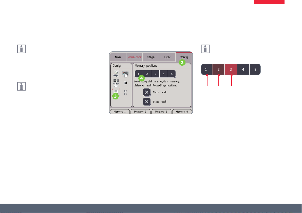
Saving Scenarios
The Leica SmartTouch™ can store up to
5 scenarios and reproduce them later at
the touch of a button. These include the focus,
the position of the stage, uorescence lter and
more.
If the iris and zoom are encoded, but not
automated, when calling up a scenario,
you are prompted to set the memory position
manually. For this purpose, the value of the
memory position and the current position are
displayed on the touchscreen.
Saving a scenario
1. Adjust the zoom, position of the stage,
lter wheel etc. to the positions you want
to save.
2. Touch the "Cong" tab.
3. Touch the symbol for assigning the memory
locations.
4. Press approx. 3 seconds on the memory
location you want to assign the current
scenario to.
The color-coding of a key indicates
whether a memory location has already
been assigned a scenario:
2
1
1. Available memory location
2. Assigned memory location
3. Assigned, active memory location
3
Leica SmartTouch™ Manual 80
Page 81

Calling Up Scenarios
Calling up using touchscreen
1. Touch the "Cong" tab.
2. Touch the symbol for assigning the memory
locations.
3. Touch the desired memory location.
Calling up using the hardware keys
The easiest way to call up frequently used
scenarios is using the hardware keys of
the Leica SmartTouch™.
1. Save a scenario as described on
page 80.
2. Touch the "Cong" tab.
3. Touch the symbol for conguring the operating buttons.
4. Touch the desired operating button.
5. Under "Memory", select the memory location that contains the desired scenario.
Leica SmartTouch™ Manual 81
Page 82

Safety Measures for Focus and Stage
The focus and/or the stage position can
be excluded when saving. In this way, you
can prevent the objective from colliding with a
specimen when you call up a memory location
that moves the objective far downwards. This
also prevents the motorized mechanical stage
from changing its position when a scenario is
called up.
Excluding the focus and/or stage
1. Touch the "Cong" tab.
2. Touch the symbol for assigning the memory
locations.
3. Touch the assigned memory location.
4. Touch "Focus recall" and/or "Stage recall" so
that these two components are no longer
controlled by the memory.
Leica SmartTouch™ Manual 82
 Loading...