

Page 1
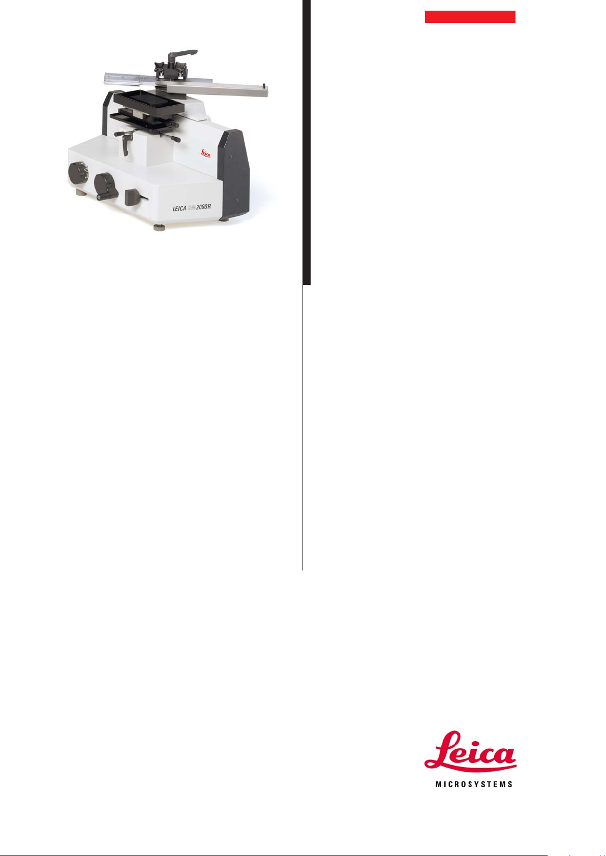
Leica SM2000 R
Sliding Microtome
Instruction Manual
Leica SM2000R – V2.1 English – 03/2004
Always keep this manual near the instrument!
Read carefully prior to operating the instrument!
Page 2

Page 3
1. Important information
Serial No. ...................................................................
Year of manufacture ................................................
Manufactured in: .. Federal Republic of Germany
The model, serial number and year of manufacture are
specified on the nameplate on the left of the instrument.
The information, numerical data, notes and value judgments contained in this manual represent the current
state of scientific knowledge and state-of-the-art technology as we understand it following thorough investigation in this field. We are under no obligation to update the present manual periodically and on an ongoing basis according to the latest technical developments, nor to provide our customers with additional
copies, updates etc. of this manual.
For erroneous statements, drawings, technical illustrations etc. contained in this manual we exclude liability as far as permissible according to the national
legal system applicable in each individual case. In particular, no liability whatsoever is accepted for any financial loss or consequential damage caused by or
related to compliance with statements or other information in this manual.
Statements, drawings, illustrations and other information as regards contents or technical details of the
present manual are not to be considered as warranted
characteristics of our products. These are determined
only by the contract provisions agreed between ourselves and our customers.
Leica reserves the right to change technical specifications as well as manufacturing processes without
prior notice. Only in this way is it possible to continuously improve the technology and manufacturing techniques used in our products.
This document is protected under copyright laws. Any
copyrights of this document are retained by Leica
Biosystems Nussloch GmbH.
Any reproduction of text and illustrations (or of any
parts thereof) by means of print, photocopy, microfiche,
web cam or other methods – including any electronic
systems and media – requires express prior permission in writing by Leica Biosystems Nussloch GmbH.
For the instrument serial number and year of manufacture, please refer to the name plate at the back of
the instrument.
© Leica Biosystems Nussloch GmbH
Leica Biosystems Nussloch GmbH
Heidelberger Str. 17-19
D-69226 Nussloch
Germany
Telephone: 0 62 24/143-0
Telefax: 0 62 24/143-200
eMail: histo_info@leica-microsystems.com
Homepage: http://www.histo-solutions.com
Leica SM2000 R – Sliding Microtome
3
Page 4

2. Table of contents
1. Important information ........................................................................................................................ 3
2. Table of contents ................................................................................................................................ 4
3. Safety instructions for handling the instrument........................................................................... 5
3.1 Safety devices ....................................................................................................................................... 5
4. Technical data..................................................................................................................................... 7
5. General description............................................................................................................................ 8
5.1 Leica SM2000R - Overview ................................................................................................................................ 8
5.2 General description...........................................................................................................................................10
5.3 Standard delivery ................................................................................................................................ 10
6. Unpacking and Setup....................................................................................................................... 11
6.1 Unpacking ........................................................................................................................................................... 11
6.2 Site requirements ..............................................................................................................................................11
6.3 Setup ...................................................................................................................................................................12
6.4 Mounting the accessories................................................................................................................. 13
7. Operating the instrument ................................................................................................................ 14
7.1 Mounting and orienting the specimen ...........................................................................................................14
7.2 Clearance angle adjustment on the knife holder .........................................................................................14
7.3 Inserting the knife or disposable blade holder ............................................................................................. 14
7.4 Trimming ............................................................................................................................................................. 15
7.5 Sectioning ............................................................................................................................................ 15
8. Trouble shooting ............................................................................................................................... 16
9. Cleaning and maintenance ............................................................................................................. 17
9.1 Cleaning .............................................................................................................................................................. 17
9.2 Maintenance........................................................................................................................................ 17
10. Accessories ....................................................................................................................................... 18
10.1 Disposable blade holder ...................................................................................................................................18
10.2 Section waste tray ............................................................................................................................................18
10.3 Distance plate for knife holder ......................................................................................................... 18
11. Ordering information ....................................................................................................................... 19
12. Warranty and service ...................................................................................................................... 20
4
Instruction manual V2.1 – 03/2004
Page 5
3. Safety instructions for handling the instrument
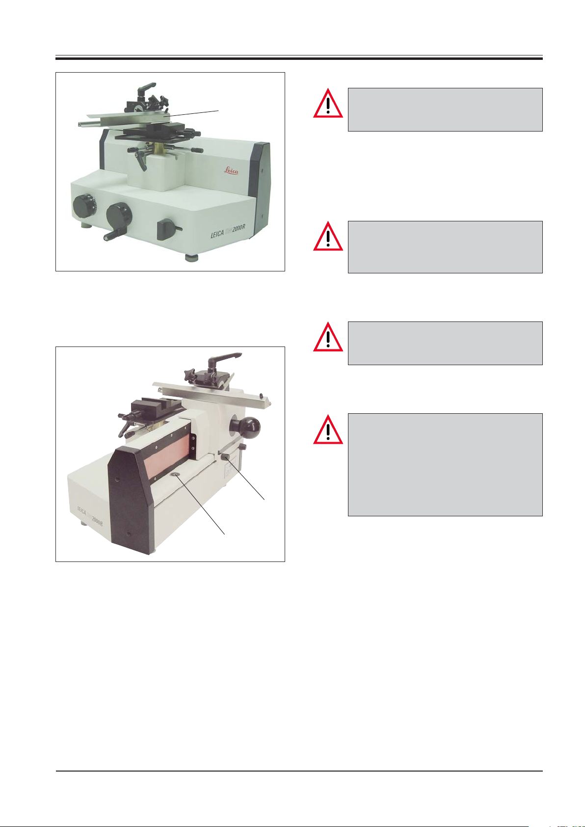
3.1 Safety devices
Fig. 5.1
14
The safety devices on the instrument and accessory equipment must not be removed or
modified!
The instrument incorporates the following safety devices: Knife guard (14) on the knife holder, knife sledge
locking knob (23) and magnetic knife sledge immobilizer (24).
Knife guard on the knife holder
Prior to manipulating the knife or specimen,
or changing the knife or specimen, and during breaks, always cover the cutting edge
with the knife guard (14)!
Knife sledge locking knob
Prior to changing the specimen or knife and
before transporting the instrument, lock the
knife sledge with the locking screw (23).
Fig. 5.2
24
23
Magnetic knife sledge immobilizer
Caution! The knife sledge movement is extremely smooth. It may occur that the sledge
moves during section removal.
To prevent the sledge from moving accidentally, pull it to the front limit of the slideway,
where it is held in position by the magnetic
knife sledge immobilizer (24), before removing the section.
Leica SM2000 R – Sliding Microtome
5
Page 6
3. Safety instructions for handling the instrument
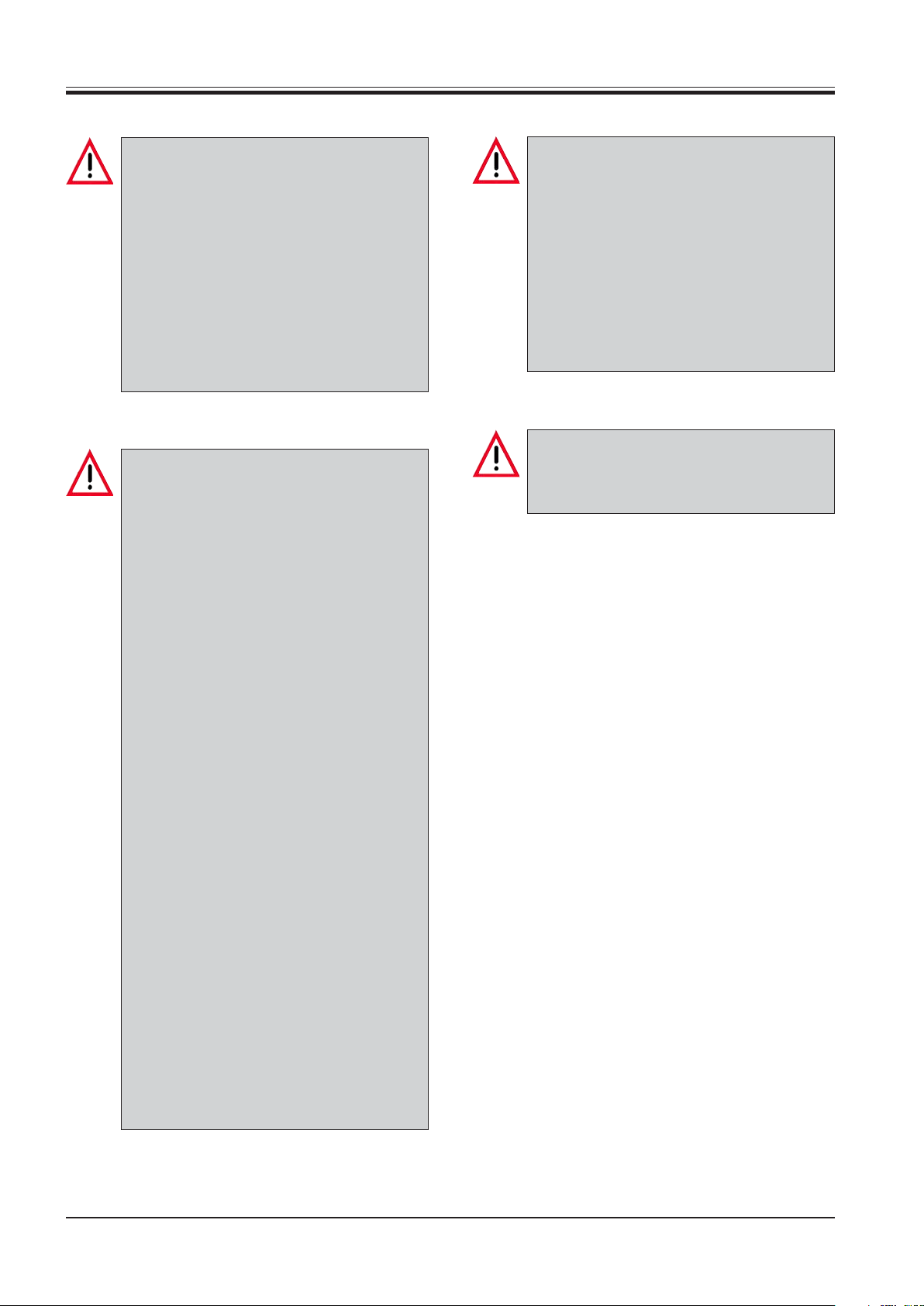
Transport and setup
• The instrument must be transported in an
upright position!
• Before transporting the instrument, the
knife sledge must be locked with the locking screw (23, Fig. 4.2)!
• Do not carry the instrument by holding it at
movable parts!
• The safety devices on the instrument and
accessory equipment must not be removed
or modified!
Operating the instrument
• Take care when handling microtome
knives and disposable blades!
The cutting edge is extremely sharp and
may cause severe injury!
• Never leave knives and knife holders with
a mounted knife or blade lying around! Always put the knives back into the knife
case when not in use!
Cleaning
• Before cleaning, remove the knife or disposable blade!
• Do not use solvents that contain acetone
or xylene!
• Ensure that no liquids enter the interior of
the instrument when cleaning!
• When using detergents, please comply
with the safety precautions of the manufacturer!
Maintenance
• Only qualified and authorized service personnel may access the internal components of the instrument for service and repair!
• Do not place a knife on a table with the
cutting edge facing upwards!
• Never try to catch a falling knife!
• Caution! The knife sledge movement is extremely smooth. It may occur that the
sledge moves during section removal.
To prevent the sledge from moving accidentally, pull it to the front limit of the
slideway, where it is held in position by
the magnetic knife sledge immobilizer (24),
before removing the section.
• Always clamp the specimen first clamping before the knife!
• Prior to manipulating the knife or specimen, or changing the specimen or knife,
and during breaks, always cover the cutting edge with knife guard and lock the
knife sledge with the locking knob!
• Always wear protective glasses when
sectioning brittle specimens!
Risk of splintering!
6
Instruction manual V2.1 – 03/2004
Page 7

Type SM 2000 R
Sliding microtome
Operating
temperature range: +10°C to +40°C
Section thickness
setting: 1-60 μm
0-2 μm in 0.5 μm increments
2-10 μm in 1 μm increments
10-20 μm in 2 μm increments
20-60 μm in 5 μm increments
Automatic
specimen advance: 0-30 μm
Overall feed: 40 mm
Dimensions and weight
Width: 300 mm
Depth: 440 mm
Height: 330 mm
4. Technical data
Weight
(incl. knife holder): 25.5 kg
Leica SM2000 R – Sliding Microtome
7
Page 8

5. General description
5.1 Leica SM2000R - Overview
Parts list
1 Section thickness adjusting knob
2 Coarse feed wheel
3 Manual feed
4 Mount for specimen clamp
5 Specimen cylinder
6 Universal cassette clamp
6a 2 attachment screws (universal cassette clamp) - see Fig. 13.1
7 Standard specimen clamp
7a 4 attachment screws (standard specimen clamp) - see Fig. 13.1
8 Locking lever for specimen orientation
9 Adjusting screw for specimen orientation - x-axis
10 Adjusting screw for specimen orientation - y-axis
11 Knife sledge
12 Grip for knife sledge movement
13 Knife holder
14 Knife guard
15 Disposable blade holder (optional accessory)
16 Knife clamping screw
17 Clamping lever for knife holder
18 4 holes in the knife sledge for mounting the knife holder (covered by the knife holder
in Fig. 7.1 and 7.2, see Fig 12.1)
19 Clamping screw for clearance angle adjustment
20 Adjusting lever for clearance angle
21 Clearance angle scale
22 Adjusting knob for automatic feed
23 Locking screw for knife sledge
24 Magnetic knife sledge immobilizer
25 Height adjustment screws
26 Section waste tray (optional accessory)
27 Distance plate for knife holder (optional accessory, Fig. 18.2)
8
Instruction manual V2.1 – 03/2004
Page 9

5. General description
17
15
16
14
6
4
9
8
5
1
2
3
Fig. 9.1
10
25
13
26
20
19
7
Fig. 9.2
21
11
12
22
23
24
Leica SM2000 R – Sliding Microtome
9
Page 10

5. General description
5.2 General description
5.3 Standard delivery
The Leica SM2000R is a manually operated sliding microtome.
The micrometer feed system is located in an enclosed housing. The microtome has
maintenance-free cross roller bearings. Lubricating is therefore not required.
The knife holder can be mounted in any of the four mounting positions on the knife
sledge. The knife holder is designed to accommodate both conventional microtome
knives or a disposable blade holder and has an integrated knife guard. The knife or
disposable blade holder does not need to be removed for clearance angle adjustment.
The microtome can be fitted with a standard specimen clamp for paraffin blocks or a
universal cassette clamp.
The Leica SM2000R was designed to conform with the directives of the European
Union and manufactured using most up-to-date quality control procedures certified
under DIN EN ISO 9001.
The Leica SM 2000 R is available in three configurations:
Leica SM 2000 R without specimen clamp
Leica SM 2000 R with universal cassette clamp
Leica SM 2000 R with fixed-jaw standard specimen clamp
The basic instrument includes the following:
1 Tool set:
-1 Allen key, size 3 14 0194 04764
-1 Single-ended open-jaw wrench, size 10 14 0330 04158
1 Dust cover 14 0212 18961
1 Section waste tray 14 0453 25167
1 Instruction manual Leica SM2000R- G/E/F/S 14 0453 80001
You will find these accessories as well as any further accessories that you may have
ordered, in the cardboard box of the instrument.
Compare the delivered components with the parts list and your order. Should you find
any discrepancies, please contact your Leica sales office without delay.
10
Page 11

6.1 Unpacking
6.2 Site requirements
6. Unpacking and Setup
First check the shipment for external damages upon arrival. If it is evident
that the shipment was damaged during transport, please make a claim to the
carrier immediately.
• Open the cardboard box.
• Remove all foam material.
• Take out all accessories and the instruction manual.
Do not carry the instrument holding it at movable parts!
• To lift the instrument from the box, hold it at the lower part of the housing and
place it on a stable, vibration-free laboratory table.
The installation site must meet the following requirements:
- Stable, plane surface
- Room temperature always between +10°C and +40°C
- Relative air humidity should not exceed 80 %.
11
Page 12

6. Unpacking and setup
6.3 Setup
11
Loosening the knife sledge locking screw
18
Screw (23) secures the knife sledge during
transport.
In daily operation it is also used lock the knife
sledge in place.
• Loosen the screw (23) at the rear of the instrument
to move the knife sledge (11).
25
Fig. 12.1
2
23
12
11
25
Testing the instrument functions
• To test the knife sledge movement hold the sledge
(11) at the grip (12) and move it repeatedly back and
forth over the entire length of the slideway.
• Test the object cylinder movement by turning the
coarse feed wheel (2).
Counterclockwise turning moves the object cylinder
(5) up.
Clockwise turning moves the object cylinder down.
When reaching the upper or lower limit, the wheel cannot be turned further.
Horizontal alignment
The microtome is horizontally aligned at the factory. If
a completely level or horizontal surface is not available at the installation site the instrument can be adjusted to the conditions.
• To horizontally align the instrument, adjust the
height adjustment screws (25) using a size 10 fork
wrench.
Fig. 12.2
12
Instruction manual V2.1 – 03/2004
Page 13

6.4 Mounting the accessories
7a
6a
6. Unpacking and setup
If there is no specimen clamp, mount the
specimen clamp now.
Mounting the specimen clamp
7
Fig. 13.1
6b
Two specimen clamps are available: the universal cassette clamp (6) and the standard specimen clamp (7)
with a fixed and movable jaw.
6
• Fix the universal cassette clamp (6) to the mount (4,
Fig. 7.1) with the two screws (6a) using an Allen key
size 3. The clamping lever (6b) should be directed
to the operator.
• Fix the standard specimen clamp (7) to the mount
(4, Fig. 7.1) with the four screws (7a) using an Allen
key size 3.
Mounting the knife holder
4 mounting positions are available for the
knife holder to meet different sectioning requirements. The knife holder can be mounted
in any of the 4 holes of the knife sledge.
The plastic grip of the clamping lever can be
repositioned as preferred by the user.
Pull the grip out of the lever, hold it in this position, and turn it to the desired position. It will
lock automatically when released.
13
Fig. 13.2
18
17
• Screw the clamping lever (17) for the knife holder
(13) down in one of the four holes (18, Fig. 10.1) of
the knife sledge (11).
• Push the base plate of the knife holder (13) against
the clamping lever (17) and fully screw the lever
down until the knife holder is securely fixed.
Oblique positioning of the knife holder
• Loosen the clamping lever (17) and position the knife
holder (13) as required.
• Retighten the clamping lever (17) to fix the knife
holder in position.
Leica SM2000 R – Sliding Microtome
13
Page 14

7. Operating the instrument
16
15
9
6
8
10
14
7.1 Mounting and orienting the specimen
Prior to manipulating the knife or specimen,
or changing the specimen or knife, and during breaks, always cover the cutting edge
with knife guard and lock the knife sledge
with the locking knob!
• Clamp an embedding cassette in the universal cassette clamp (6) or a paraffin block in the standard
specimen clamp (7).
• To orient the specimen surface towards the knife,
loosen the locking lever (8).
• Orient the sample by means of the adjusting screws
(9) and (10).
• Retighten the locking lever (8) after orienting.
Fig. 14.1
Fig. 14.2
21
16
20
19
7.2 Clearance angle adjustment on the knife
holder
• Loosen the clamping screw (19) and the knife
clamping screw (16).
• Select the desired angle with the adjusting lever (20)
on the clearance angle scale (21).
• Retighten the clamping screws (19) and (16) to fix
the angle setting.
7.3 Inserting the knife or disposable blade
holder
Take care when handling microtome knives
and disposable blades!
The cutting edge is extremely sharp and may
cause severe injury!
• Unscrew the knife clamping screw (16) on the knife
holder.
• Carefully insert the knife or disposable blade holder
(15, Fig. 14.1) with the blade into the knife holder
from the left and hold in place.
• To clamp turn the knife clamping screw (16) clockwise.
The screw does not need to be fully tightened. Good
sectioning results may be obtained when the screw
is tightened with a medium effort.
14
Instruction manual V2.1 – 03/2004
Page 15

7. Operating the instrument
7.4 Trimming
For trimming, the specimen feed can be disengaged
either by turning the coarse feed wheel (2) or by operating the manual feed lever (3).
1
2
Fig. 15.1
14
11
• Hold the knife sledge (11) at the grip (12) and place
the sledge behind the specimen.
• Pull the knife guard (14) of the knife holder to the
right.
• To feed the specimen towards the knife, turn the
coarse feed wheel (2) counterclockwise;
or
select the required section thickness with the section thickness adjusting knob (1) and pull the manual
feed lever to the front (3). Each lever activation
3
causes a specimen feed by the selected value. The
coarse feed wheel will turn at the same time.
• Move the knife sledge forth and back until the speci-
men surface is trimmed as required.
7.5 Sectioning
• Select the required section thickness with the sec-
tion thickness adjusting knob (1, Fig. 15.1).
When using the automatic advance feature,
make sure to move the knife sledge against
the limit stop position to disengage an automatic feed after each section.
Fig. 15.2
24
22
The position of the adjusting knob (22) determines the
point where the automatic feed takes place. The feed
should take place immediately before the specimen,
or behind the sample from the operator‘s view.
• To use the automatic feed feature, loosen the ad-
justing knob (22), place it in the required position,
and retighten the knob.
• To produce the section, pull the knife sledge over
the specimen at a constant speed.
Caution! The knife sledge movement is extremely smooth. It may occur that the sledge
moves during section removal.
To prevent the sledge from moving accidentally, pull it to the front limit of the slideway,
where it is held in position by the magnetic
knife sledge immobilizer (24), before removing the section.
• Carefully remove the section with a small brush.
Leica SM2000 R – Sliding Microtome
15
Page 16

8. Trouble shooting
Possible causeProblem Correction
Thick/thin sections
The section thickness varies from one
section to another. In extreme cases,
sections are skipped meaning that a
section is not obtained.
Compressed sections
The sections are extremely compressed, wrinkled or jammed together.
- Insufficient knife/blade inclination;
consequently the clearance angle is
too small.
- Insufficient clamping of specimen
and/or knife.
- Blunt knife/blade.
- Blunt knife/blade.
- Specimen too warm.
- Clearance angle too big.
Systematically try several clearance
angle adjustments, until the optimum
angle is found.
- Check if all levers are locked and
screws are tightened on the specimen and knife holder systems. Retighten the levers and screws if necessary.
- Use a different part of the knife or
blade edge or use a new knife/blade.
- Use a different part of the knife or
blade edge or use a new knife/blade.
- Precool the specimen on a cold
plate.
- Cool the specimen in iced water immediately before sectioning.
- Systematically decrease the clearance angle until the optimum adjustment is obtained.
Sections exhibit scratches and chatter
marks.
No specimen feed takes place. No section obtained.
- Clearance angle too big.
- Inappropriate knife profile.
- Insufficient clamping of specimen
and/or knife.
- Upper feed limit reached.
- Systematically decrease the clearance angle until the optimum adjustment is obtained.
- Use knife with different profile.
- Check if all levers are locked and
screws are tightened on the specimen and knife holder systems. Retighten the levers and screws if necessary.
- Turn the coarse feed wheel clockwise to lower the specimen.
16
Instruction manual V2.1 – 03/2004
Page 17

9.1 Cleaning
9.2 Maintenance
9. Cleaning and maintenance
The painted surfaces are not resistant against acetone or xylene.
Only use mild commercial detergents or soap solution for cleaning!
Ensure that no liquids enter the interior of the instrument when cleaning!
Before cleaning, remove the knife or disposable blade!
• Clean the painted surfaces with commercial detergents or soap solution.
Standard lacquer cleaners are recommended for the lacquer finish.
• Anodized parts such as specimen clamps may be cleaned with solvent.
Only qualified and authorized service personnel may access the internal components of the instrument for service and repair!
The microtome is virtually maintenance-free. To ensure a smooth operation of the
instrument over several years we recommend the following:
• Have the instrument inspected once a year by a qualified service engineer authorized by Leica.
• Enter into a service contract at the end of the warranty period.
For further information, please contact your local Leica service center.
• Clean the instrument every day.
• Lubricate the object cylinder (5, Fig. 7.1), and knife holder (13) with the oil No. 405
from time to time.
Leica SM2000 R – Sliding Microtome
17
Page 18

10. Accessories
10.1 Disposable blade holder
Fig. 18.1
15a
16
15
26
Instead of a conventional microtome knife, a disposable blade holder (15) can be inserted in the knife
holder.
• To clamp the disposable blade, loosen the three
screws (15a), carefully insert the blade, and retighten the screws evenly.
• To insert the disposable blade holder into the knife
holder, unscrew the knife clamping screw (16) sufficiently, and insert the disposable blade holder
between the jaws of knife holder from the left, and
retighten the clamping screw (16).
• Select the appropriate clearance angle (see 7.2).
10.2 Section waste tray
The section waste tray (26) protects the microtome
housing against paraffin debris. With the section waste
tray section debris is collected can be disposed of rapidly and easily.
• Place the section waste tray (26) on the horizontal
surface of the microtome from the left.
Fig. 18.2
13
27
27a
27a
10.3 Distance plate for knife holder
When sectioning very high blocks, the mounting position of the knife holder can be increased by using a
distance plate (27). The distance plate is delivered with
an overlength clamping lever (27a).
• Carefully remove the knife or disposable blade
holder from the knife holder.
• Remove the knife holder from the knife sledge.
• Screw the clamping lever (27a) in any of the four
holes (18, Fig. 10.1) of the knife sledge.
• Place the distance plate (27) and knife holder (13)
on the knife sledge, push the slot against the clamping lever (27a), and screw the clamping lever (27a)
down until knife holder and distance plate are firmly
secured.
27
Fig. 18.3
18
Instruction manual V2.1 – 03/2004
Page 19

11. Ordering information
SM2000R sliding microtome - Basic instrument ............................................................................................. 14 0453 25122
SM2000R sliding microtome - Basic instrument with universal cassette clamp .......................................14 0453 25120
SM2000R sliding microtome - Basic instrument with standard specimen clamp .....................................14 0453 25121
Accessories
Universal cassette clamp ....................................................................................................................................14 0413 24198
Standard specimen clamp ..................................................................................................................................14 0413 18850
Disposable blade holder EC 240 H for high profile blades including
dispenser of 50 disposable blades, 2 clamping plates, fixing screws and tools ........................................ 14 0368 26456
Disposable blade holder EC 240 L for low profile blades including
dispenser of 50 disposable blades, 2 clamping plates, fixing screws and tools ........................................ 14 0368 26457
Distance plate for knife holder including overlength clamping lever .......................................................... 14 0413 18967
Section waste tray................................................................................................................................................14 0453 25167
Dust cover ..............................................................................................................................................................14 0212 18961
Consumables
Dispenser of 50 disposable blades - high profile.............................................................................................14 0358 12881
Dispenser of 50 disposable blades - low profile ..............................................................................................14 0358 13583
Leica SM2000 R – Sliding Microtome
19
Page 20

12. Warranty and service
Warranty
Leica Biosystems Nussloch GmbH guarantees that the contractual product delivered
has been subjected to a comprehensive quality control procedure based on the Leica
in-house testing standards, and that the product is faultless and complies with all
technical specifications and/or agreed characteristics warranted.
The scope of the warranty is based on the content of the concluded agreement. The
warranty terms of your Leica sales organization or the organization from which you
have purchased the contractual product shall apply exclusively.
Technical service information
If you require technical service or replacement parts, please contact your Leica sales
representative or dealer who sold the product.
Please provide the following information:
• Model name and serial number of the instrument.
• Location of the instrument and name of the person to contact.
• Reason for the service call.
• Date of delivery.
Decommissioning and disposal
The instrument or parts of the instrument must be disposed of in compliance with the
local laws.
20
Instruction manual V2.1 – 03/2004
Page 21

13. EC Declaration of Conformity
EC Declaration of Conformity
We herewith declare, in exclusive responsibility, that the instrument
Leica SM2000 R – Sliding Microtome
was developed, designed and manufactured to conform with the
• Directive 2006/42/EC of the European Parliament and of the Council on machinery
The following harmonized standards were applied:
• DIN EN ISO 12100-1: 2003
Safety of machinery.
Basic concepts, general principles for design.
Part 1: Basic terminology, methodology
• DIN EN ISO 12100-2: 2003
Safety of machinery.
Basic concepts, general principles for design.
Part 2: Technical principles and specifications.
In addition, the following in-house standards were applied:
• DIN EN ISO 9001: 2000.
Quality management systems - Requirements
Leica Biosystems Nussloch GmbH
Heidelberger Str. 17-19
D-69226 Nussloch
May 14, 2008
Leica SM2000 R – Sliding Microtome
. . . . . . . . . . . . . . . . . . . . . . . . . . . . . . . . . .
Anne De Greef-Safft
President Biosystems Devision
21
Page 22

22
Instruction manual V2.1 – 03/2004
 Loading...