


Version 1.1
English
Leica HDS6000
User Manual

Introduction
Introduction
Purchase Congratulations on the purchase of a HDS6000 instrument.
This manual contains important safety directions as well as instructions for setting
up the product and operating it. Refer to "6 Safety Directions" for further information.
Read carefully through the User Manual before you switch on the product.
2HDS6000
Product
identification
The type and the serial number of your product are indicated on the type plate.
Enter the model and serial number in your manual and always refer to this information when you need to contact your agency or Leica Geosystems authorized service
workshop.
Type: _______________
Serial No.: _______________
Network Address: _______________
IP Address: _______________

Symbols The symbols used in this manual have the following meanings:
Type Description
Danger Indicates an imminently hazardous situation which, if not
Warning Indicates a potentially hazardous situation or an unintended
Caution Indicates a potentially hazardous situation or an unintended
)
Trademarks • Windows is a registered trademark of Microsoft Corporation
• Bluetooth is a registered trademark of Bluetooth SIG, Inc
All other trademarks are the property of their respective owners.
Introduction HDS6000 3
avoided, will result in death or serious injury.
use which, if not avoided, could result in death or serious injury.
use which, if not avoided, may result in minor or moderate
injury and/or appreciable material, financial and environmental
damage.
Important paragraphs which must be adhered to in practice as
they enable the product to be used in a technically correct and
efficient manner.

Table of Contents
Table of Contents
In this manual Chapter Page
1 Description of the System 7
1.1 Instrument Components 7
1.2 Cabling 14
1.2.1 Operate the HDS6000 with the Battery 14
1.2.2 Operate the HDS6000 with the Battery Charger
1.2.3 Operate the HDS6000 with the External Battery 22
1.3 Field of View (FOV) 27
1.4 HDS
2 Setting Up the Instrument 31
2.1 General Information 31
2.2 Scanner Setup on Tripod 32
2.3 Setup the HDS6000 Over a Benchmark 34
2.4 Instrument Height 37
2.5 Setting Up the Instrument with the Dolly 38
3 Preparing to Scan 41
3.1 Switch On/Off the System 41
3.2 Preparations 42
(AC power supply) 20
Cyclone
Software Suite 28
4HDS6000

3.3 Ambient Conditions 46
3.4 HDS6000 Controls 49
3.4.1 HDS6000 Control Buttons 49
3.4.2 Menu Control 50
3.5 Scanning 57
3.6 Data Management 63
3.7 Settings 64
3.8 Updating the Firmware 70
3.9 Connections 71
3.10 Network 72
3.10.1 Connecting the HDS6000 by Cable to the Network 73
3.10.2 Connecting the HDS6000 to a Notebook 75
3.11 Operating the HDS6000 using a Web Browser 77
3.12 HDS6000 and WLAN Connection 82
4 Troubleshooting 84
5 Care and Transport 87
5.1 Check & Adjust 87
5.2 Transport 88
5.3 Storage 89
5.4 Cleaning and Drying 90
5.5 Window Cleaning Procedure 91
5.6 Adjustment of the Circular Level 93
5.7 Service of the Tripod 95
Table of Contents HDS6000 5

Table of Contents
6HDS6000
6 Safety Directions 96
6.1 General Description 96
6.2 Intended Use 97
6.3 Limits of Use 99
6.4 Responsibilities 100
6.5 International Warranty, Software Licence Agreement 101
6.6 Hazards of Use 103
6.7 Laser Classification Scanner, Visible Laser 111
6.8 Electromagnetic Compatibility EMC 117
6.9 FCC Statement, Applicable in U.S. 120
7 Technical Data 126
7.1 General Technical Data of the Instrument 126
7.2 System Performance 127
7.3 Laser Scanning System 129
7.4 Electrical 132
7.5 Environmental 133
7.6 Physical 135
7.7 Accessories 135
7.8 WLAN 140
7.9 Conformity to National Regulations 141
1 Description of the System
24V
6,3
AM
i
j
k
l
m
n
a
b
c
d
f
e
g
h
HDS6000_001
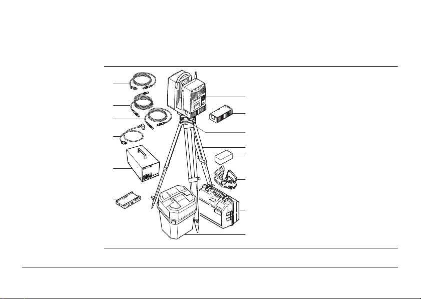
1.1 Instrument Components
Overall system
a) HDS6000
b) Rechargeable internal battery
("battery" will be used)
c) Tribach
d) Tripod
e) Cleaning kit
f) Carrying straps
g) Transport box for power supply
h) Transport box for HDS6000
i) Ethernet cable
j) HDS6000 power supply cable
k) Charging cable (optional)
l) Battery charger power cable
m) KNL-24 battery charger/AC power
supply
("battery charger" will be used)
n) Charging cradle
Description of the System HDS6000 7
Description of the System
24V
6,3 AM
HDS6000_007
d
e
a
b
c
f
Hardware options • External Battery TRAPP-15-24
• HDS6000 scan targets and target accessories
• Dolly
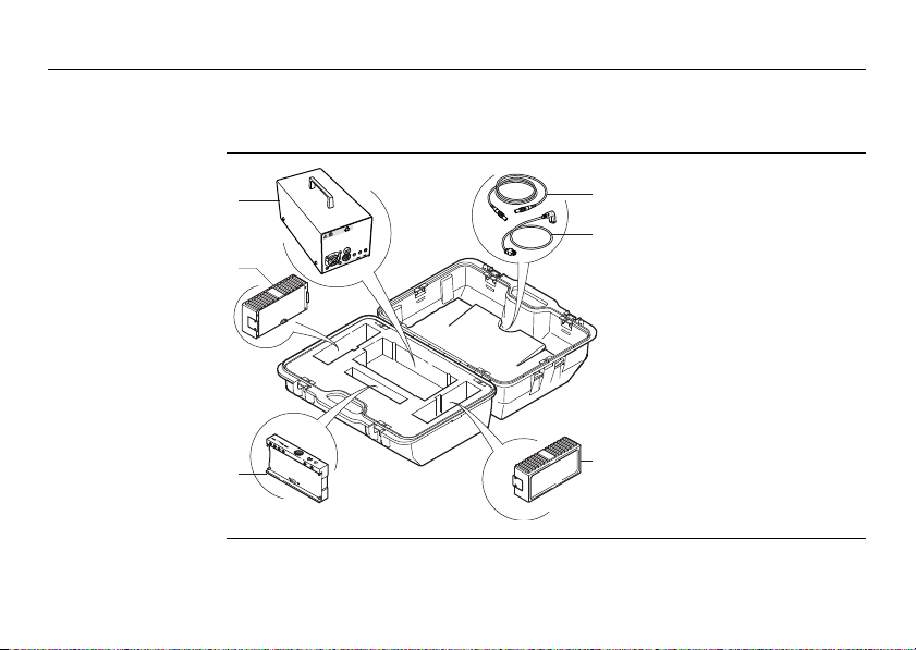
Transport box for
power supply
8HDS6000
a) Battery charger
b) Battery
c) Charging cradle
d) Charging cable
e) Battery charger power
cable; three different types
delivered
f) Battery
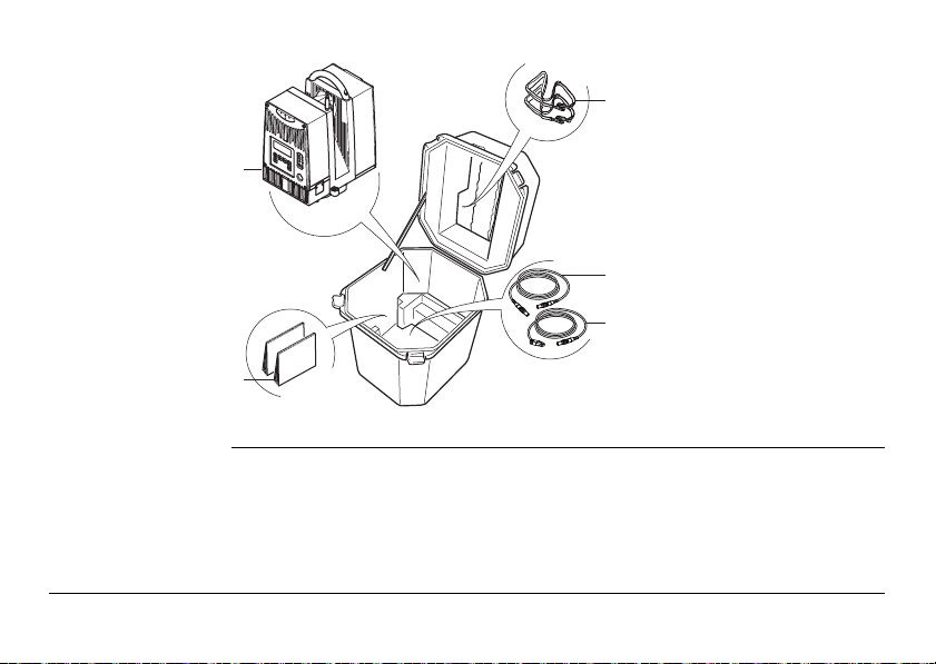
Transport box for
HDS6000
c
a
d
a) HDS6000
e
b) Manuals
b
c) Carrying straps
d) HDS6000 power supply
cable
HDS6000_007a
e) Ethernet cable
Description of the System HDS6000 9
Description of the System
a
b
c
e
d
g
h
j
k
l
i
f
HDS6000_002
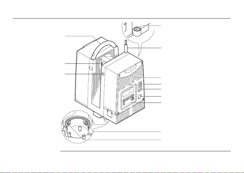
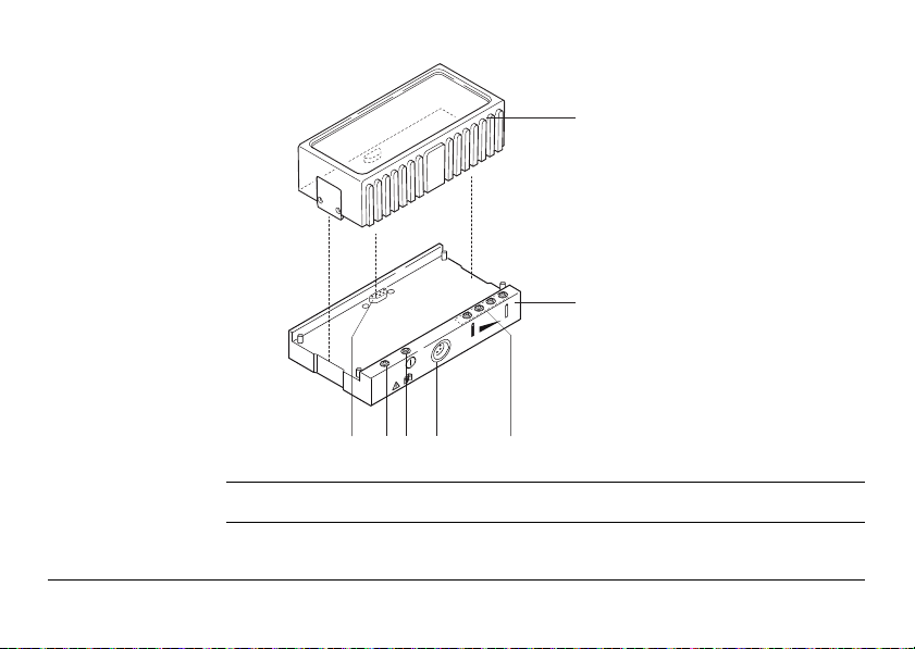
HDS6000
10HDS6000
a) Handle
b) Mirror (Laser exit)
c) Laser active light, flashes
while scanning
d) Circular level
e) Antenna
f) Display
g) USB Connectors, P1, P2
h) Lemo Connectors (not
supported), P3, P4
i) ON/OFF button
j) Keyboard
k) Ethernet connector
l) Connector for power
supply
Battery and
a
b
cdefg
HDS6000_003
ERR
charging cradle
)
Description of the System HDS6000 11
Use the SupD-9 plug only for connecting to the battery.
a) Battery
b) Charging cradle
c) Battery status indicators
d) Connector for power supply
e) Power indicator LED
f) Error LED
g) SupD-9 plug; connects
battery and charging cradle
Description of the System
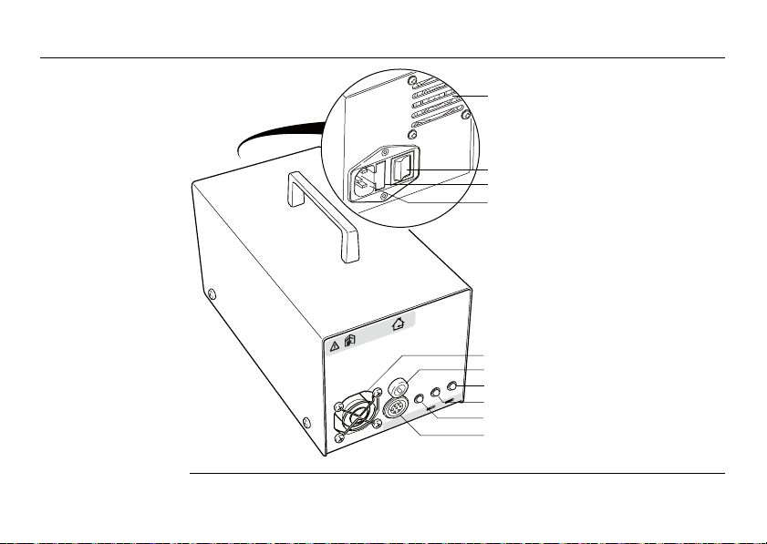
Battery charger
HDS6000_066
12HDS6000
a
b
c
d
a) Air inlet
b) Mains switch
c) Fuse
d) Mains plug
e) Fan
e
f) Fuse
f
g) Green LED, showing battery
g
is fully charged
24V
6,3 AM
h
h) Yellow LED
i
i) Power indicator LED
j
j) Power output
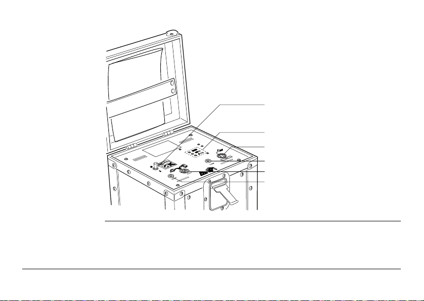
External battery
HDS6000_067
b
a
e
f
d
c
TRAPP-15-24
a) Main switch
b) Battery status indicators
c) Output additional voltage,
not used
d) Fuse for additional voltage,
3.15 AM
e) Main output
f) Fuse for main output,
6.3 AFF
Description of the System HDS6000 13
Description of the System
HDS6000_021
1
1
2
1.2 Cabling
1.2.1 Operate the HDS6000 with the Battery
14HDS6000
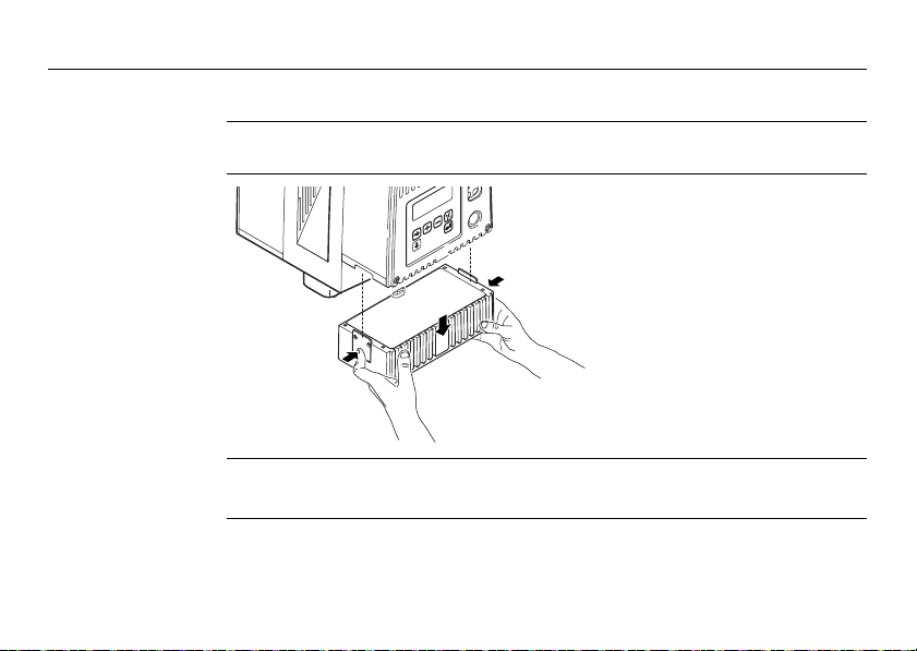
Change the battery
)
1. Hold the battery with both
hands and press the fixing
clips.
2. Pull the battery carefully
downwards.
A battery should always be attached to ensure the optimum weight balance for the
HDS6000.

)
Never remove the battery while the HDS6000 is switched on.
Precautions:
• Switch off the HDS6000 beforehand or
• use the external power supply
)
Description of the System HDS6000 15
Primary use/charging
• The battery must be charged prior to using it for the first time because it is delivered with an energy content as low as possible.
• For new batteries or batteries that have been stored for a long time (> three
months), it is effectual to make only one charge/discharge cycle.
• For Li-Ion batteries, a single discharging and charging cycle is sufficient. We
recommend carrying out the process when the battery capacity indicated on the
charger or on a Leica Geosystems product deviates significantly from the actual
battery capacity available.
• The permissible temperature range for charging is between 0°C to 40°C / +32°F
to +104°F. For best results the recommended temperature range for charging is
between +10°C and +20°C.
• It is normal for the battery to become warm during charging. Using the chargers
recommended by Leica Geosystems, it is not possible to charge the battery if the
temperature is too high.

Description of the System
Operation/Discharging
• The batteries can be operated from 0°C to 40°C / +32°F to °104°F.
• Low operating temperatures reduce the capacity that can be drawn; very high
16HDS6000
operating temperatures reduce the service life of the battery.
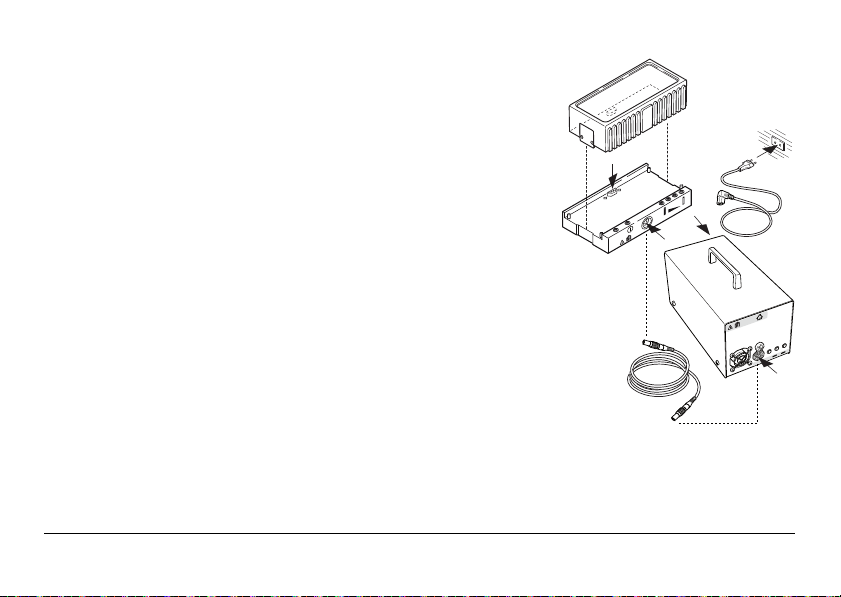
Charging the
battery
1. Turn off the battery charger.
2. Plug the power cable into the battery charger
and into an A/C plug.
3. Using the charging cable connect the
charging cradle and the battery charger.
4. Place the battery onto the charging cradle.
5. Turn on the battery charger. Its power indicator LED switches on.
6. After 30sec initialization, the charging
cradle’s battery status indicators will indicate
the current battery charging status.
7. After charging the battery, turn off the
battery charger.
8. Disconnect the cables.
HDS6000_004
4
2
2
3
ERR
V
4
2
M
A
3
,
6
3
)
Charging of the battery takes approximately 1.5 hours.
Description of the System HDS6000 17
Description of the System
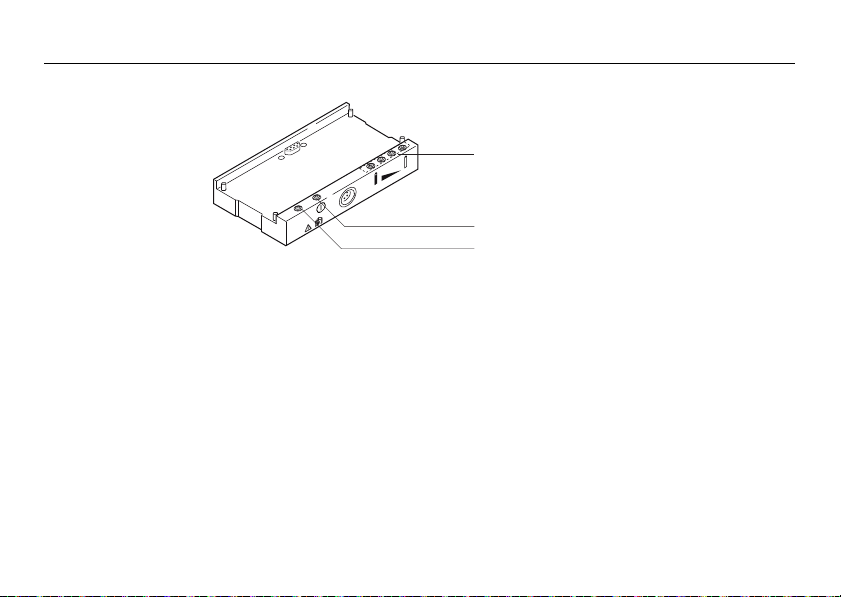
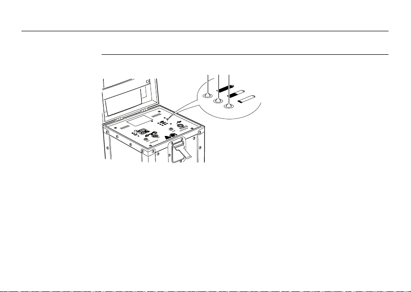
Understand the charging cradle’s LEDs:
18HDS6000
a
ERR
HDS6000_006
Battery status
indicators
b
c
a) Battery status indicators
b) Power indicator LED
c) Error LED
• If all four LEDs flash continuously then there is no battery in
the charging cradle.
• The overall charging capacity of the battery is divided into
quarters. Each LED corresponds to a quarter:
• If the battery charge state is low the appropriate LED
flashes slowly.
• The LED flashes faster as the charge state improves.
• If an LED illuminates constantly the battery has reached
the appropriate level of charge.
• When all four LEDs illuminate constantly the battery is
100% charged.
Error LED The red LED illuminates if there is a fault in the electricity supply.
Power indicator
LED
Danger To avoid electrical shock, outdoor use of the battery charger is not permitted.
Danger Death or serious injury can occur if product is not connected to ground.
Description of the System HDS6000 19
Precautions:
Use the battery charger in dry indoor environments only.
Precautions:
To avoid electric shock power cable and power outlet must be grounded.
Please refer to "HDS6000 Battery" in "4 Trouble-shooting".
The green power indicator LED illuminates if the charging cradle
is under voltage.
Laite on liitettävä suojamaadoituskoskettimilla varustettuun
pistorasiaan.
Apparatet må tillkoples jordet stikkontakt.
Apparaten skall anslutas till jordat uttag.
Description of the System
20HDS6000
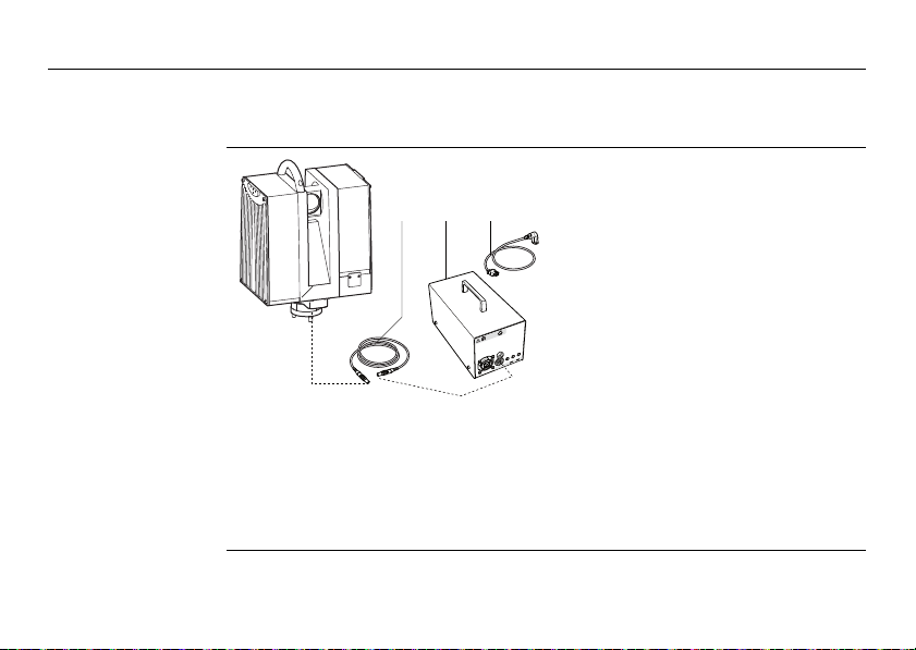
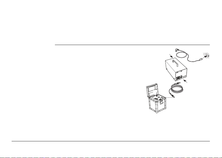
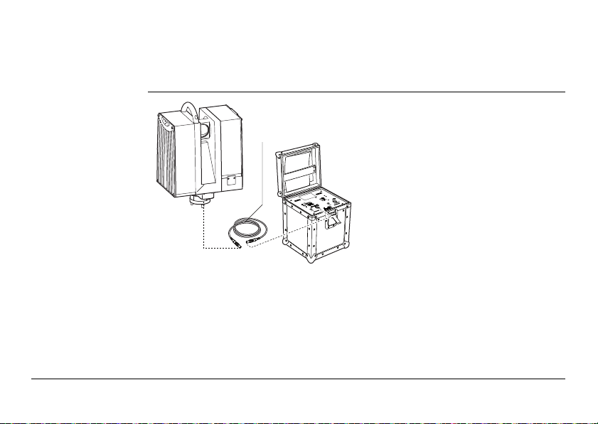
1.2.2 Operate the HDS6000 with the Battery Charger (AC power supply)
Operate the
HDS6000 with the
battery charger
cba
a) HDS6000 power supply cable
b) Battery charger
c) Battery charger power cable
HDS6000_005
V
4
2
M
A
3
,
6
1. Verify that the battery charger is off.
2. Connect the battery charger power cable.
3. Connect the HDS6000 and the battery charger with the HDS6000 power supply
cable.
4. Turn on the battery charger.
Caution To avoid connector damage, turn off the battery charger before connecting it to the
Danger To avoid electrical shock, outdoor use of the battery charger is not permitted.
Danger Death or serious injury can occur if product is not connected to ground.
Description of the System HDS6000 21
HDS6000.
Precautions:
Use the battery charger in dry indoor environments only.
Precautions:
To avoid electric shock power cable and power outlet must be grounded.
Laite on liitettävä suojamaadoituskoskettimilla varustettuun
pistorasiaan.
Apparatet må tillkoples jordet stikkontakt.
Apparaten skall anslutas till jordat uttag.
Description of the System
1.2.3 Operate the HDS6000 with the External Battery
22HDS6000
Understand the
external battery
condition indicators
a b c
a) Green LED
b) Yellow LED
HDS6000_068
c) Red LED
If the external battery is turned on and not connected to the scanner:
Green LED External battery is fully charged and ready to use.
Yellow LED External battery is empty and must be recharged before use.
Red LED External battery is completely empty and must be recharged
immediately to avoid battery damage.
If the external battery is turned on and connected to the scanner:
HDS6000_063
2
4
V
6
,
3
A
M
2
2
4
3
Green LED External battery is fully charged.
Yellow LED External battery is half empty.
Red LED External battery is empty and must be charged to avoid auto-
matic shut down of the scanner.
Charge the
external battery
1. Turn off the external battery and the battery
charger.
2. Connect the battery charger power cable.
3. Connect the charging cable to the Main
Output of the external battery.
4. Connect the charging cable to the output of
the battery charger.
5. Turn on the battery charger.
6. A yellow battery charger LED means that the
battery is being charged.
7. A green battery charger LED means that the
battery is fully charged.
8. After charging the battery, turn off the
battery charger.
9. Disconnect the charging cable.
Description of the System HDS6000 23
Description of the System
Danger To avoid electrical shock, outdoor use of the battery charger is not permitted.
Danger Death or serious injury can occur if product is not connected to ground.
Precautions:
Use the battery charger in dry indoor environments only.
Precautions:
To avoid electric shock power cable and power outlet must be grounded.
Laite on liitettävä suojamaadoituskoskettimilla varustettuun
pistorasiaan.
Apparatet må tillkoples jordet stikkontakt.
Apparaten skall anslutas till jordat uttag.
24HDS6000
Period of use, life
span of the
external battery
Understand the external batteries period of use and life span:
• The period of use ranges from 2.5 to 6 hours and depends on the electrical load,
temperature, and usage cycles.
• After 200 to 300 cycles, consider contacting Leica Geosystems or your distributor
to replace the battery.
Before storing the external battery for a longer period of time, recharge it to
HDS6000_069
a
)
avoid shortening the life span.
Before storage, turn off the external battery.
Operate the
HDS6000 with the
external battery
a) HDS6000 power supply cable
To avoid connector damage, turn off the external battery before connecting it to the
)
Description of the System HDS6000 25
HDS6000.
Precautions:
1. Verify that the external battery is off.
2. Connect the HDS6000 power supply cable to the HDS6000 and the external
battery.

Description of the System
3. Turn on the external battery.
4. To turn on the external battery after it has automatically turned off, turn the
)
26HDS6000
• A red external battery LED means that the external battery is empty and must
be recharged immediately after finishing the current scan. If the external
battery is further discharged, it turns off automatically without further
warning. If the power is turned off while scanning, the software can fail and
you can lose data.
switch from the "On" position to the "Off" position and back again to the "On"
position.
In addition to the battery indicator of the external battery, the remaining
power is also displayed by the software when connected. This display is an
approximation and can differ from the status shown by the external battery.
In this case, the display of the external battery is valid.
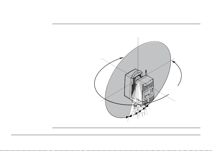
1.3 Field of View (FOV)
HDS6000_008
25°
25°
310°
360°
Field of view The HDS6000 has a rotating mirror system that covers a 360 x 310 degree field of
view.
Description of the System HDS6000 27

Description of the System
1.4 HDS
Cyclone
28HDS6000
Software Suite
General Leica Geosystems HDS
widest set of work process options for 3D laser scanning projects in engineering,
surveying, construction and related applications.
The Software consist of five packages:
•
Cyclone
-Scan:
allows the user to control the Scanner.
•
Cyclone
-Register:
allows the user to register multiple Scans together or to Geo-reference the point
cloud.
•
Cyclone
-Survey:
gives the user basic functionality to extract and measure information from the
rich point cloud.
•
Cyclone
-Model:
gives the user the full functionality of
measure features and to create a 3D Model out of the PointCloud.
•
Cyclone
-PUBLISHER:
allows users to publish point cloud data to a panoramic viewing format which can
be posted to the Web. Users can then view this data with the Internet Explorer
plug-in Leica TruView.
Cyclone
software modules provide point cloud users with the
Cyclone
. The user is able to extract and

)
• For more information on
http://www.leica-geosystems.com/hds/en/lgs_3490.htm
•
Cyclone
Software has also an online help available, which can be accessed
through the F1 key on your keyboard.
Cyclone
Software Suite, please visit:
General Operating
Principles
Description of the System HDS6000 29
• Download:
Cyclone
Software, as well as important Support documentation, can be downloaded from the Leica Geosystems HDS Website
(http://www.leica-geosystems.com/hds/en/lgs_27048.htm).
The User must create an account before the download section is accessible.
• Installation:
You must use a Windows account with administrator privileges to install or
upgrade
Plant® Review.
Cyclone
, CloudWorx for AutoCAD, or CloudWorx for Intergraph Smart-

Description of the System
Windows 2000 users:
)
If
Cyclone
Plant® Review fails to launch with an "entry point HeapSetInformation"
error message after installing or upgrading,
A) install Windows 2000 Service Pack 3 or Service Pack 4 with all avail-
B) install the Microsoft hotfix for KB816542 (download and unzip the
, CloudWorx for AutoCAD, or CloudWorx for Intergraph Smart-
able security updates (recommended), or
file, then run "Windows2000-KB816542-x86-ENU.exe" to install the
hotfix).
30HDS6000
1. Download the
2. Run the Installation file.
3. Follow the onscreen instructions and select the software you wish to
4. Go to the License Request Page.
• Language:
Cyclone
's operating Language is English.
install.
Cyclone
Installshield from the website specified above.
 Loading...