


DM4000M

Leica DM4000 B
Leica DM4000 M
Leica DM5000 B
Operating Manual
1

Published 2003 by:
Leica Microsystems Wetzlar GmbH
Ernst-Leitz-Straße
D-35578 Wetzlar (Germany)
Responsible for contents:
Katja Peter, Karin Schwab
Marketing CM, Compound Microscopy, Product Management
In case of questions, please contact:
2
Phone +49(0)6441-292261
Fax +49(0)6441-292255
E-mail: MQM-Hotline@leica-microsystems.com
Leica DM4000 B
Leica DM4000 M
Leica DM5000 B
Operating Manual
3

Copyrights
Copyrights
All rights to this documentation are held by Leica
Microsystems Wetzlar GmbH. Reproduction of
text or illustrations (in whole or in part) by print,
photocopy, microfilm or other methods (including electronic systems) is not allowed without
express written permission from Leica
Microsystems Wetzlar GmbH.
The term "Windows" can be used in the following
text without further identification. It is a
registered trademark of the Microsoft
Corporation. Otherwise, no inference with
regard to the free usability of product names
may be drawn from the use of those names.
The instructions contained in the following documentation reflect state-of-the-art techno-logy
and knowledge standards. We have compiled
the texts and illustrations as accurately as
possible. Nevertheless, no liability of any kind
may be assumed for the accuracy of this manual’s contents. Still, we are always grateful for
comments and suggestions regarding potential
mistakes within this documentation.
The information in this manual is subject to modification at any time and without notification.
4

Contents
Contents
1. Important Notes about this Manual ..... 7
2. Safety Notes .............................................. 8
2.1. General Safety Notes ............................... 8
2.2. Electrical Safety ........................................ 8
3. Overview of the Instrument .................... 10
4. Unpacking the Microscope .................... 14
5. Assembling the Microscope .................. 16
5.1 Stage ........................................................... 17
5.2 Condenser .................................................. 18
5.3 Tube and Eyepieces ................................. 19
5.4 Objectives .................................................. 19
5.5 Light Sources for the
Transmitted Light Axis ............................. 20
5.6 Light Sources for the
Incident Light Axis .................................... 21
5.7 Equipping the
Incident Light filter turret ........................ 26
5.8 Polarizer and Analyzer ............................. 27
5.9 DIC Prisms .................................................. 28
5.10 Optional Accessories ............................... 29
5.11 Connection to the Power Supply............ 30
5.12 Connection to the
CTR5000 Electronics Box ......................... 30
6. Startup ........................................................ 31
6.1 Functional Principle.................................. 31
6.2 Switching on the Microscope ................ 34
6.3 The Display
(Leica DM4000 B/DM4000 M) ................. 35
6.4 The Function Keys .................................... 36
6.5 Köhler Illumination .................................... 37
6.6. Checking Phase Contrast Rings ............. 39
6.7 Adjusting the Light Sources .................... 40
7. Operation ................................................... 46
7.1 Switching on the Microscope ................ 46
7.2 Stages and Specimen Displacement .... 46
7.3 Focusing ..................................................... 47
7.4 Tubes...........................................................
48
7.5 Eyepieces ................................................... 49
7.6 Objectives .................................................. 50
7.7 Magnification Changer ............................ 51
7.8 Light Sources ............................................. 52
7.9 Aperture Diaphragm and
Field Diaphragm ........................................ 52
8. Imaging Procedure for
Leica DM4000 B/Leica DM5000 B ......... 53
8.1 Transmitted Light ...................................... 53
8.1.1 Bright Field ...................................... 53
8.1.2 Phase Contrast ............................... 53
8.1.3 Dark Field......................................... 54
8.1.4 Polarization ..................................... 55
8.1.5 Differential
Interference Contrast .................... 56
5

Contents
8.2 Fluorescence ............................................. 57
9. Imaging Procedure for
Leica DM4000 M ....................................... 58
9.1 Incident Light ............................................. 58
9.1.1 Bright Field ...................................... 58
9.1.2 Dark Field......................................... 58
9.1.3 Polarization ..................................... 59
9.1.4 Interference Contrast .................... 60
9.2 Transmitted Light ...................................... 60
9.2.1 Bright Field ...................................... 60
10. Trouble Shooting ...................................... 61
11. Care of the Microscope ........................... 64
11.1 Dust Cover .................................................. 64
11.2 Cleaning ...................................................... 64
11.3 Handling Acids and Bases ...................... 65
12. Essential
Wear and Spare Parts ............................. 66
13. Abbreviations and Pictograms .............. 67
14. Index ........................................................... 68
15. EU Declaration of Conformity ................ 69
6
1. Important Notes about this Manual
1. Important Notes about this Manual
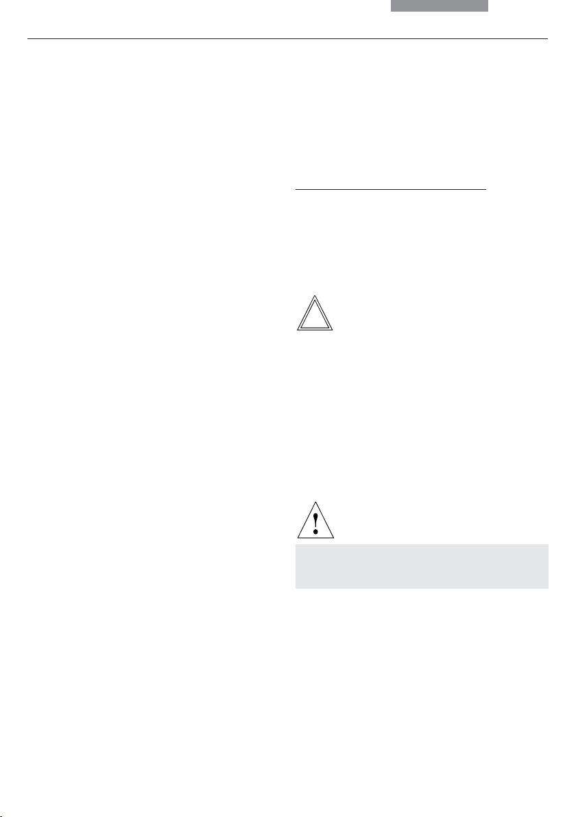
Caution!
This operating manual is an essential component of the microscope, and must be read
carefully before the microscope is put into
operation or used.
Text symbols and their meanings:
(1.2)
→ p. 20
!
This operating manual contains important instructions and information for the operational
safety and maintenance of the microscope and
accessories. Therefore, it must be kept and
taken care of.
Numbers in parentheses, such as "(1.2)", correspond to illustrations (in the example, Figure 1,
Item 2).
Numbers with pointer arrows (for example
→ p.20), point to a certain page of this manual.
Special safety instructions are indicated
with the triangle symbol shown here, and
have a gray background.
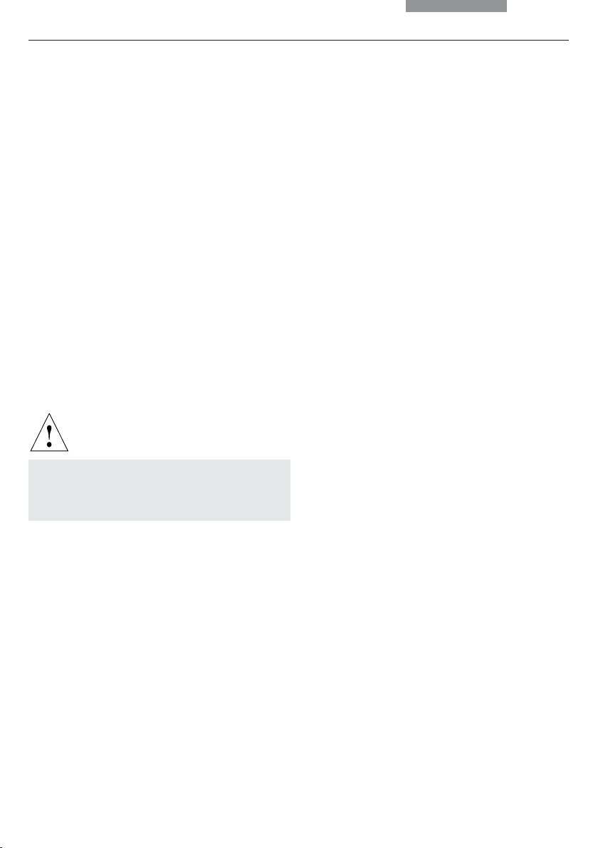
Caution! The microscope and accessories can
be damaged when operated incorrectly.
Explanatory note.
*
Item not contained in all configurations.
7
2. Safety Notes
2. Safety Notes
2.1 General Safety Notes
This safety class 1 device is constructed and
tested in accordance with EN 61010-1/IEC 1010-1,
safety regulations for electrical measuring, control, and laboratory devices.
Caution!
In order to maintain this condition and to ensure safe operation, the user must follow the
instructions and warnings contained in this
operating manual.
Caution!
The devices and accessories described in
this operating manual have been tested for
safety and potential hazards.
The responsible Leica affiliate or the main
plant in Wetzlar must be consulted whenever the device is altered, modified or used
in conjunction with non-Leica components
that are outside of the scope of this manual.
Unauthorized alterations to the device or
noncompliant use shall void all rights to any
warranty claims!
2.2 Electrical Safety
General specifications
Leica CTR5000 electronics box (for DM5000 B)
For indoor use only.
Supply voltage:
Frequency:
Power input:
Fuses:
Ambient temperature:
Relative humidity:
Overvoltage category:
Pollution degree:
Microscope
For indoor use only.
Supply voltage:
Frequency:
Power input:
DM4000
DM5000
Fuses:
DM4000
DM5000
Ambient temperature:
Relative humidity:
Overvoltage category:
Pollution degree:
90-250 V~
50-60 Hz
max. 290 VA
T6,3 A
(IEC 60127-2/3)
15-35°C
max. 80% to 30°C
II
2
90-250 V~
50-60 Hz
max. 180 VA
max. 290 VA
T6,3 A
(IEC 60127-2/3)
See CTR5000
15-35°C
max. 80% to 30°C
II
2
8

Supply unit ebq 100
For indoor use only.
Supply voltage:
Frequency:
Power input:
Fuses:
Ambient temperature:
Relative humidity:
Overvoltage category:
Pollution degree:
(see enclosed manual)
Caution!
90-250 V~
50-60 Hz
max. 155 VA
2xT2A (IEC 127)
15-35°C
max. 80% to 30°C
II
2
2. Safety Notes
Caution!
Never use any fuses as replacements other
than those of the types and the current ratings listed here. Using patched fuses or
bridging the fuse holder is not permitted.
Caution!
The microscope’s electrical accessory components are not protected against water.
Water can cause electric shock.
The power plug may only be plugged into an
outlet equipped with a grounding contact.
Do not interfere with the grounding function
by using an extension cord without a ground
wire. Any interruption of the ground wire inside or outside of the device, or release of
the ground wire connection, can cause the
device to become hazardous. Intentional
ground interruption is not permitted!
Caution!
Through connection to the grounding connection, ancillary equipment with its own
and/or extra power supply may be brought to
the same ground wire potential. For
connections without a ground connector,
Leica Service must be consulted.
Caution!
Protect the microscope from excessive temperature fluctuations. Such fluctuations can
lead to the accumulation of condensation,
which can damage the electrical and optical
components.
Ambient temperature: 15-35°C.
Caution!
Before exchanging the fuses or lamps, be
absolutely certain to switch-off the main
power switch and remove the power cable.
9

3. Overview of the Instrument
3. Overview of the Instrument
Specification
Imaging Procedure
Transmitted Light Axis
Incident Light Axis
Z Pinion
Leica DM4000 B / DM5000 B
• transmitted light: BF, DF, PH,
Pol (DM5000 B also ICT)
• incident light: fluorescence
• automatic Illumination Manager
(motorized aperture diaphragm and field diaphragm,
motorized intensity control)
• automatic Constant Color Intensity Control (CCIC)
• motorized shutter
• integrated into the stand
• motorized 5x filter turret
(DM5000 B 8x optional)
• with FIM (Fluorescence
Intensity Managemer) for decreasing light intensity in 5
stages
• mechanical “Booster Lens”
for increasing fluorescence
intensity
• motorized shutter
• manual
Leica DM4000 M
• transmitted BF, DF, PH
light: ICT, Pol
• incident light: BF, DF, ICR, Pol
• integrated into the stand
• motorized 4x filter turret
• automatic Illumination
Manager
• motorized shutter
Objective nosepiece
X/Y Stage
Tube
10
• manual
• absolute coded
• 6x with M25 thread
(DM5000 B: 7x; mot. DIC
objective prism turret with 4
positions optional)
• manual
• replaceable specimen stage
• coaxial pinion length: 155 mm
• manual or motorized
• optionally with two camera outputs
• manual
• absolute encoded
• 6x with M32 thread
• slot for DIC prisms
and Pol compensators
(optional)
• manual
• replaceable specimen stage
• coaxial pinion length: 140 mm

3. Overview of the Instrument
Specification
Condenser
Magnification Changer
Control Panels
Computer Interface
Software Tools
Leica DM4000 B / DM5000 B
• motorized condenser head
• motorized condenser turret for light rings,
DF stop, DIC prisms
• optional polarizer integrated and motorized
• automatic Köhler Illumination
• manual
• absolute coded
• 1x; 1.25x; 1.6x
• operating buttons for all motorized microscope functions
• additional variable function keys
• focusing knobs
• LC display
• DM5000 B with LeicaScreen (touchscreen)
• RS232C
• Leica DMControl for Windows
• with plugins for:
• customitsation
• DM Operation
(remote control)
• basic Image Viewer
Leica DM4000 M
• manual
• absolute coded
• 1x; 1.5x; 2x
TM
2000, XP, NT;
CTR5000
Electronics Box
For Leica DM5000 B only:
Separate control unit with
power supply for 100W halogen
lamp
see p. 8 (electrical safety)
11
3. Overview of the Instrument
14
1
2
3
4
5
6
8910111213
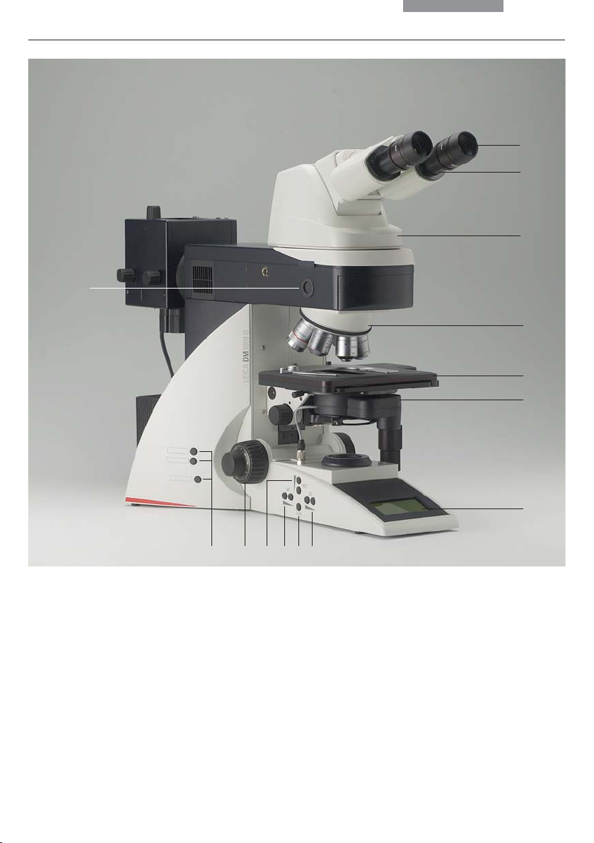
Fig. 1 Leica DM4000 M left side of the stand with AET22 advanced ergotube
1 Eyepiece
2 Eyepiece tube
3 Tube
4 Objective nosepiece with objectives
5 Specimen stage with specimen holder
6 Condenser
7 LC display
8 Function keys field diaphragm
9 Transmitted light/incident light switch
10 Function keys aperture diaphragm
11 Function keys: Light intensity
12 Focus dial with coarse and fine adjustment
13 Variable function keys (factory pre-assigned)
14 Lamp adjustment window
12
7

22
3. Overview of the Instrument
15
16
21 20 19 18 17
Fig. 2 Leica DM4000 B right side of the stand with Advanced Ergotube AET22
15 Lamp housing for incident light
16 Lamp housing for transmitted light
17 Transmitted light filter, optional
18 Transmitted light filter, optional
19 Variable function keys (factory pre-assigned)
20 X/Y coaxial drive, height adjustable
21 Focus fine adjustment
22 Motorized filter cube exchanger
13
4. Unpacking the Microscope
4. Unpacking the Microscope
The device is delivered in two boxes.
The stand box contains the following compo-
nents:
• Stand with integrated incident light axis and
objective nosepiece
• Specimen stage with stage bracket
• Power cable and PC connecting cable
• CD with Leica software package
• Instructions and list of microscope default
settings (“Identification Sheet”)
The system box contains the microscope acces-
sories:
• Tube
• Eyepieces
• Objectives
The external ebq 100 supply unit* is delivered in
separate packaging.
For the Leica DM5000 B microscope:
The CTR5000 electronics box is also delivered in
separate packaging.
First, carefully remove all components from the
transportation and packaging materials.
Note:
Avoid touching the lens surfaces of the
objectives. If fingerprints do appear on the glass
surfaces, remove them with a soft leather or
linen cloth. Even small traces of finger
perspiration can damage the surfaces of optical
surfaces in a short time. See the chapter, "Care
of the microscope" →
structions.
Caution!
p. 64, for additional in-
• Condenser
• Lamp housings with accessories
• Fitting tool
• Depending on configuration, additional microscope accessories such as filter cubes, etc.
14
Do not yet connect the microscope and peripherals to the power supply at this point!
4. Unpacking the Microscope
Installation location
Work with the microscope should be performed
in a dust-free room, which is free of oil vapors
and other chemical vapors, as well as extreme
humidity. At the workplace, large temperature
fluctuations, direct sunlight and vibrations
should be avoided. These conditions can distort
measurements and micrographic images.
Allowable ambient conditions
Temperature 15-35°C
Relative humidity maximum 80% up to 30°C
Microscopes in warm and warm-damp climatic
zones require special care in order to prevent
the build up of fungus.
See the chapter, "Care of the microscope" →
for additional instructions.
Caution:
Electrical components must be assembled at
least 10 cm from the wall and away from
flammable substances.
p. 64,
Transport
For shipping or transporting the microscope
and its accessory components, the original
packaging should be used.
As a precaution to prevent damage from vibrations, the following components should be disassembled and packaged separately:
• Unscrew the objectives.
• Remove the condenser.
• Remove the stage.
• Remove the lamp housings.
• Disassemble the burner of 106 z lamp housing.
• Remove all moving or loose parts.
15

5. Assembly
5. Assembling the Microscope
The microscope components are logically assembled in this order:
• Stage
• Condenser
• Tube
• Eyepieces
• Objectives
• Light sources
• Filter cubes/reflectors*
Only a few commonly used screwdrivers and
keys are necessary for assembly, which are included in the delivery package.
When using intermediate systems and optical
accessories, the sequence may vary.
In this case, read Chapter,
"5.10 Optional accessories" → p. 29
16
5. Assembly
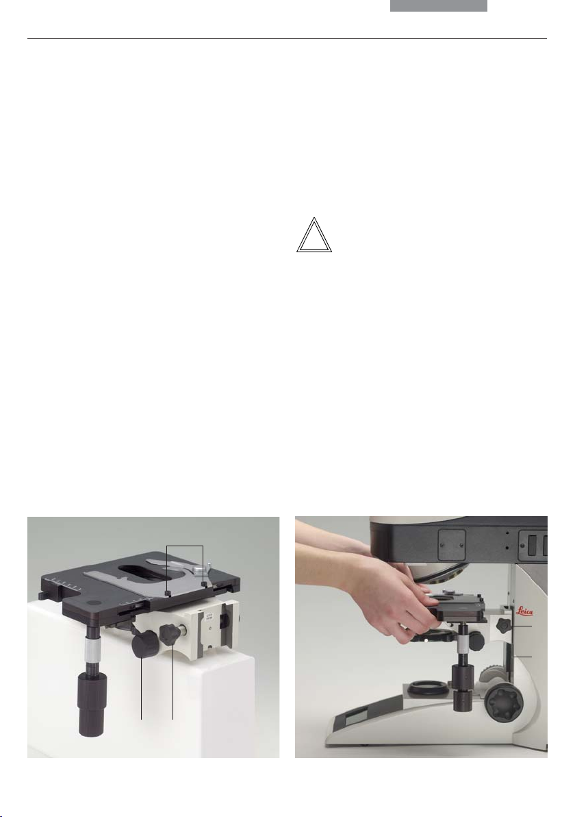
5.1 Stage
Caution:
!
Before assembling the stage, make sure no objectives are installed!
• Place the specimen holder on the stage and
fasten it with the two screws (3.1).
• Using the condenser height adjuster (3.2), turn
the condenser holder completely upwards, i.e.
as close to the stage as possible.
• Loosen the stage clamp (3.3) slightly.
Fig. 3 Mechanical object stage
1 Locking screws for specimen holder
2 Condenser height adjuster
3 Stage clamp
• From above, set the stage clamp onto the
dovetail guide (4.2) and push the stage downwards until the upper end of the dovetail guide
is tightly fastened to the upper end of the
stage clamp.
• Firmly tighten the stage clamp (4.1).
Note:
For thicker specimens (Leica DM4000 M) the
stage can be set to a correspondingly lower
level.
Fig. 4 Assembling the stage
1 Stage clamp
2 Dovetail guide
1
23
1
2
17

5. Assembly
5.2 Condenser
• Using the condenser height adjuster (5.4), turn
the condenser holder (5.1) completely downwards.
• Unscrew the clamping screw for the condenser (5.3) far enough so that the condenser
can be inserted from the front.
• From the front, insert the condenser into the
condenser holder as far as it will go. On the
underside of the condenser, there is an orientation pin (6.1), which must be located in the
guiding notch (7.1).
• Pull the condenser’s clamping screw (5.3) so
that the condenser is locked in place.
• Connect the condenser over the connection
(8.1) with the stand.
Note:
The condenser must be centered before using
the microscope.
Köhler illumination p. 37.
→
Fig. 6
Underside of condenser
1 Orientation pin
Fig. 7 Condenser holder
1 Guiding notch
1
1
Fig. 5 Condenser holder
1 Condenser holder
2 Condenser centering
3 Clamping screw for condenser
4 Condenser height adjuster
1
23 4
18
Fig. 8 Condenser connector
1 Condenser cable socket
1
5. Assembly
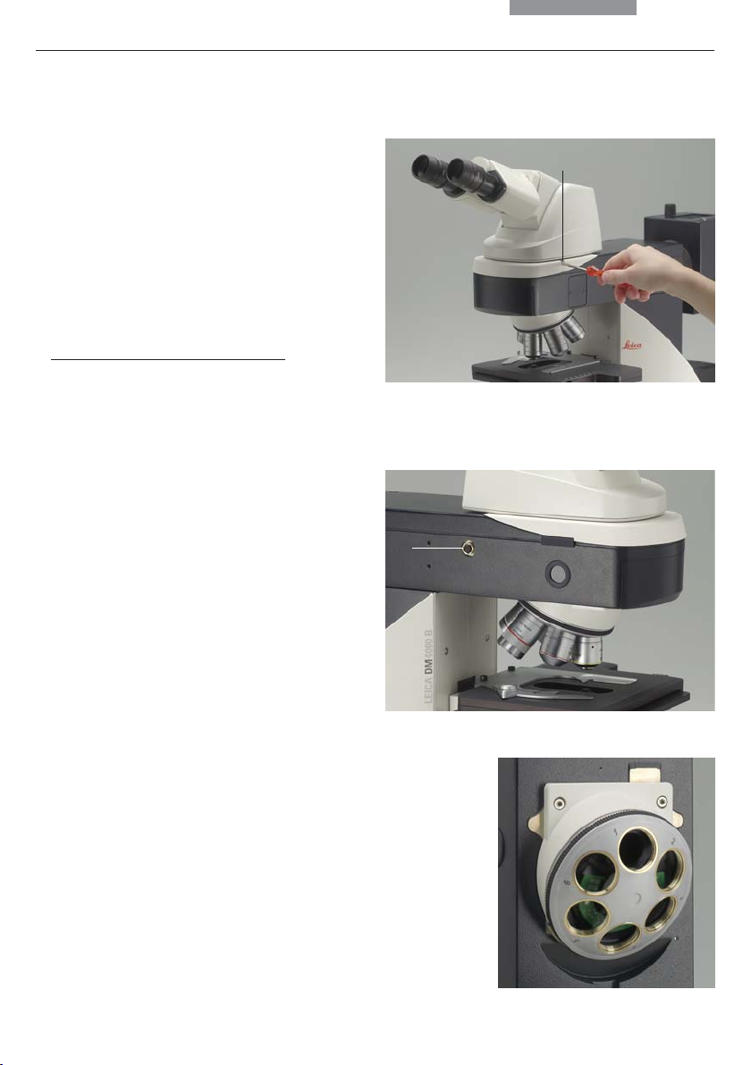
5.3 Tube and Eyepieces
The tube is mounted to the stand either directly or
with the use of intermediate modules. It is fastened
in place with the side clamping screw (9.1).
• Loosen the clamping screw (9.1).
• Insert the tube in the circular receptacle
(dovetail ring).
• Retighten the clamping screw (9.1).
Only for the MBDT motorized tube:
•
Connect the tube to the stand with the connector socket (10.1).
• The eyepieces are inserted into the eyepiece
tubes on the tube.
6.4 Objectives
The receptacles on the objective turrets are
numbered (Fig. 11). The individual objectives
have already pre-assigned positions at the
factory according to their configuration.
A list of the exact objective positions is provided
in shipment. (“Identification Sheet”)
Fig. 9 Fastening the tube
1 Clamping screw
1
Fig. 10 Motorized tube connection
1 Connector socket
1
Caution:
!
Cover unoccupied threads on the turret with
dust protector caps!
Fig. 11
Objective turret
with labeled
objective
receptacles
19
5. Assembly
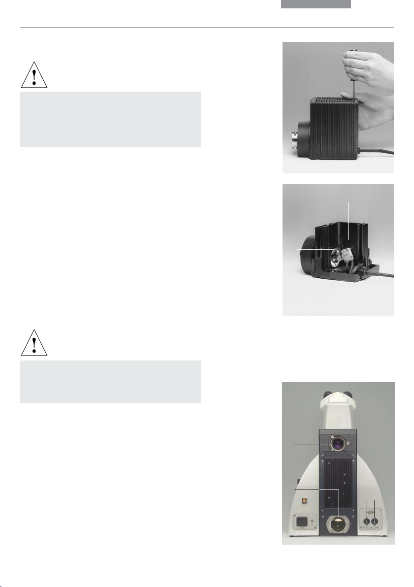
5.5 Light Sources for the Transmitted Light Axis
Caution:
Be sure that the lamp housing is disconnected from the power supply. Unplug the
power plug and the power supply during assembly.
107/2 Lamp Housing
This lamp housing is used with a 12V 100W halogen lamp, which is already mounted.
In case the lamp has to be removed:
• Remove the fastener screw on the housing
(Fig. 12).
• Remove the housing by pulling it upwards.
• Remove the lamp
• Insert the new 12V 100W lamp (13.1) with dust
cover straight into the socket until it stops. Be
sure that the lamp is inserted straight.
• Remove the lamp’s dust cover.
Caution:
Do not remove the lamp’s dust cover until
you have installed the lamp. Avoid
fingerprints on the lamp.
Fig. 12
Lamp housing 107/2
Releasing the
fastening screw
Fig. 13
Lamp housing 107/2,
opened
1 Mount with
halogen lamp
2 Collector
1
2
Fig. 14 Rear side of stand
1 Incident light lamp housing receptacle
2 Transmitted light lamp housing receptacle
3 12 V 100 W connection for transmitted light (symbol: )
4 12 V 100 W connection for incident light (symbol: )
• Replace the housing and fasten it in place using the fastening screw.
• Place the lamp housing in the transmitted light
lamp housing receptacle (14.2) and fasten it
with the clamping screw on the side.
• Connect the lamp housing to the power
supplyfor transmitted light (symbol: ) (14.3).
20
1
2
34
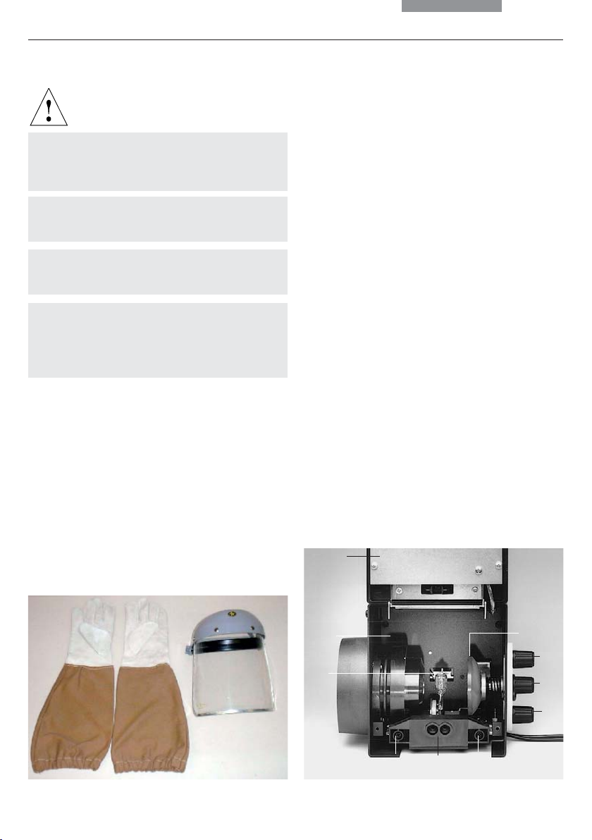
5. Assembly
5.6 Light Sources for the Incident Light Axis
Caution:
During assembly, always unplug the power
supply unit of the 106 z lamp housing from its
socket.
Never touch the glass parts of the burner
with bare hands.
Never look directly into the beam path (blinding hazard).
During assembly work on xenon burners, always wear the supplied protective gloves and
face protection (Fig. 15) (risk of explosion).
106 z lamp housing
Fig. 15
Protective gloves and mask
This lamp housing is used with a 12V 100W halogen lamp or various gas discharge lamps.
Inserting the 12V 100W halogen lamp into the
106 z lamp housing
• Unscrew the fastening screws of the cover
and lift up the cover (16.1).
• Unscrew the fastening screws of the lamp
mount (16.8) and pull out the mount (Fig. 17).
Fig. 16 106 z lamp housing (on the side, open)
1 Cover raised
2 Collector
3 12 V 100 W lamp or
gas discharge lamp in mount
4 Reflector (mirror)
5, 6, 7 Adjusting screw for x-y reflector
8 Fastening screw for lamp mount
9 Socket for contact plug
1
2
4
5
3
6
7
898
21
 Loading...