

Leica Builder T, Builder RM, Builder RM power, Builder M power, Builder R User Manual

Version 4.0
English
Leica Builder
User Manual

Introduction
Introduction
Purchase Congratulations on the purchase of a Builder series instrument.
This manual contains important safety directions as well as instructions for setting
up the product and operating it. Refer to "16 Safety Directions" for further information.
Read carefully through the User Manual before you switch on the product.
2Builder
Product
identification
The type and the serial number of your product are indicated on the type plate.
Enter the type and serial number in your manual and always refer to this information
when you need to contact your agency or Leica Geosystems authorized service workshop.
Type: _______________
Serial No.: _______________

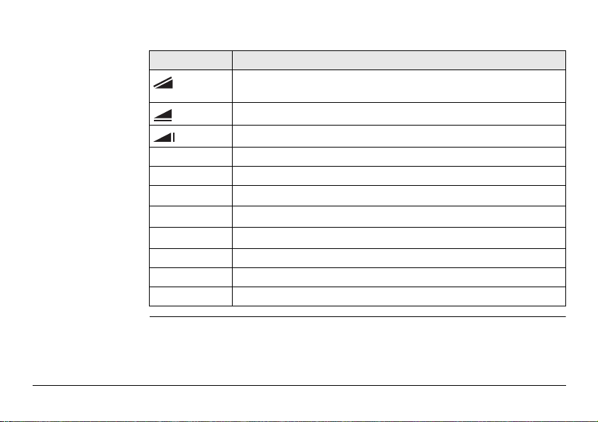
Symbols The symbols used in this manual have the following meanings:
Type Description
Danger Indicates an imminently hazardous situation which, if not
Warning Indicates a potentially hazardous situation or an unintended
Caution Indicates a potentially hazardous situation or an unintended
)
Trademarks • Windows is a registered trademark of Microsoft Corporation
All other trademarks are the property of their respective owners.
Introduction Builder 3
avoided, will result in death or serious injury.
use which, if not avoided, could result in death or serious
injury.
use which, if not avoided, may result in minor or moderate
injury and/or appreciable material, financial and environmental damage.
Important paragraphs which must be adhered to in practice
as they enable the product to be used in a technically
correct and efficient manner.
Introduction
Validity of this
manual
4Builder
Description
General This manual applies to all Builder instruments. Where there are
differences between the various models they are clearly described.
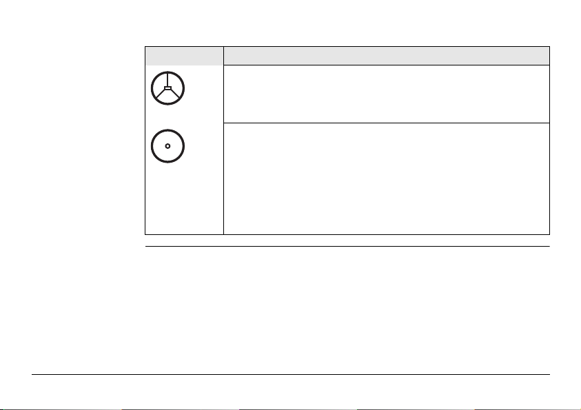
Telescope In regard to the instrument EDM, a Builder instrument may be
equipped with one of two types of telescopes, which offer the
same performance but differ in some technical details. The two
different types can be distinguished by a rectangular (telescope
type 1) or round (telescope type 2) shaped element, which is
visible in the centre of the objective lens. Where there are technical
differences between the two telescope types they are marked by
the following pictograms, referring to the first or second type
described above:
Description
Telescope Type 1
• Builder R and RM allow only measurements without prisms.
When using this EDM type a narrow visible red laser beam is
used to measure distances.
Telescope Type 2
• When measuring distances to a reflector with EDM type "fine"
or "fast" this telescope type uses a wide visible red laser beam,
which emerges coaxially from the telescope's objective. Only
possible with the Builder M power and RM power.
• Builder RM power can measure distances without prisms.
When using the EDM type "red dot" a narrow visible red laser
beam is used to measure distances.
Introduction Builder 5

Table of Contents
Table of Contents
In this manual Chapter Page
1 How to Use this Manual 12
2 Technical Terms and Abbreviations 14
3 Description of the System 20
3.1 Instrument Models 20
3.2 Set Contents 21
3.3 Instrument Components 23
3.4 Power Supply 25
3.5 Software Concept 26
4 User Interface 28
4.1 Keyboard 28
4.2 Screen 32
4.3 Tab Bar 34
4.4 Icons 35
4.5 Symbols 36
6Builder

5 Operation 38
5.1 Selection of Language 38
5.2 Instrument Setup 39
5.3 Instrument Battery 47
5.4 Distance Measurement 50
5.4.1 General 50
5.4.2 Measurement with Red Dot 51
5.4.3 Measurement with Fine or Fast 53
5.5 CPR105 Flat Prism 54
5.6 CPR111 BUILDER Prism, True-Zero Offset 55
6 Configuration Mode 56
6.1 Overview 56
6.2 Accessing 57
6.3 How to Make a Setting 68
7 Theodolite Mode 70
7.1 Overview 70
7.2 Accessing 71
7.3 How to Set Horizontal Angle to 0.000 73
7.4 How to Set Any Horizontal Angle 74
7.5 Quick Setting of Horizontal Angle and Vertical Angle Direction
Measurement 75
Table of Contents Builder 7

Table of Contents
8Builder
8 Program Mode, for Builder R, RM, M power and RM power 78
8.1 Overview 78
8.2 Accessing 79
8.3 Pointsearch 80
8.4 Measure and Record 82
9 Station Setup, for Builder R, RM, M power and RM power 84
9.1 Overview 84
9.2 Setup Option 1: Establish Control Line 86
9.2.1 General 86
9.2.2 Establish Control Line - Over 1st Point 87
9.2.3 Establish Control Line - Anywhere 88
9.3 Setup Option 2: Establish Coordinates 91
9.3.1 General 91
9.3.2 Establish Coordinates - Over Known Point 92
9.3.3 Establish Coordinates - Anywhere 94
9.4 Setup Option 3: Establish Height 96
9.4.1 General 96
9.4.2 Height Transfer 97

10 Application Programs, for Builder R, RM, M power and RM power 98
10.1 Overview 98
10.2 Layout 100
10.3 As Built 104
10.4 Angle & Distance 107
10.5 Tie Distance 109
10.6 Area plane (tilt) & Volume 112
10.7 Hidden Point (optional) 115
10.8 COGO (optional) 119
10.9 Layout Line/Arc/Spiral (optional) 128
10.10 Measure & Descriptor 134
11 Data Management Mode, for Builder RM, M power and RM power 136
11.1 Overview 136
11.2 Accessing 137
11.3 Jobs 139
11.4 Fixpoints 141
11.5 Measurements 144
11.6 Result 146
11.7 Communication Parameters 147
11.8 Data Transfer 150
11.9 Pin Assignment 151
Table of Contents Builder 9

Table of Contents
10Builder
12 EDM Settings 152
12.1 EDM 152
12.2 PPM 156
13 System Info and Instrument Protection 158
13.1 System Info 158
13.2 Instrument Protection (PIN) 161
14 Check & Adjust 164
14.1 Overview 164
14.2 Preparation 166
14.3 Combined Adjustment of Hz Collimation (c), Vertical Index (i) and
Compensator Index (l, t) Errors 167
14.4 Adjustment of the Circular Level 172
14.5 Adjustment of the Laser Plummet 174
14.6 Service of the Tripod 177
14.7 Inspection of the Red Laser Beam, for Builder R-, RM- and
RM power 178
14.8 Adjustment of the Vertical Line of the Reticule, for Builder T 180
15 Care and Transport 182
15.1 Transport 182
15.2 Storage 184
15.3 Cleaning and Drying 185

16 Safety Directions 186
16.1 General 186
16.2 Intended Use 187
16.3 Limits of Use 189
16.4 Responsibilities 190
16.5 Hazards of Use 191
16.6 Laser Classification 197
16.6.1 Integrated Distancer, Measurements with Red Dot
16.6.2 Integrated Distancer, Measurements with Fine/Fast
16.6.3 Integrated Distancer, Visible Laser (only Builder R and RM)204
16.6.4 Laser Plummet 206
16.7 Electromagnetic Compatibility EMC 209
16.8 FCC Statement, Applicable in U.S. 211
17 Technical Data 214
17.1 Angle Measurement 214
17.2 Distance Measurement 215
17.3 General Technical Data of the Instrument 220
18 International Limited Warranty, Software License Agreement 226
Index 228
Table of Contents Builder 11
(only for Builder RM power) 198
(only Builder M power and RM power) 202
How to Use this Manual
1 How to Use this Manual
12Builder
)
Index The index is at the back of the manual.
)
Validity of this
manual
Available documentation
It is recommended to set-up the instrument while reading through this manual.
Keys, fields and options on the screens which are considered as self-explanatory are
not explained.
This manual applies to all Builder instruments. Differences between the various
models are marked and described.
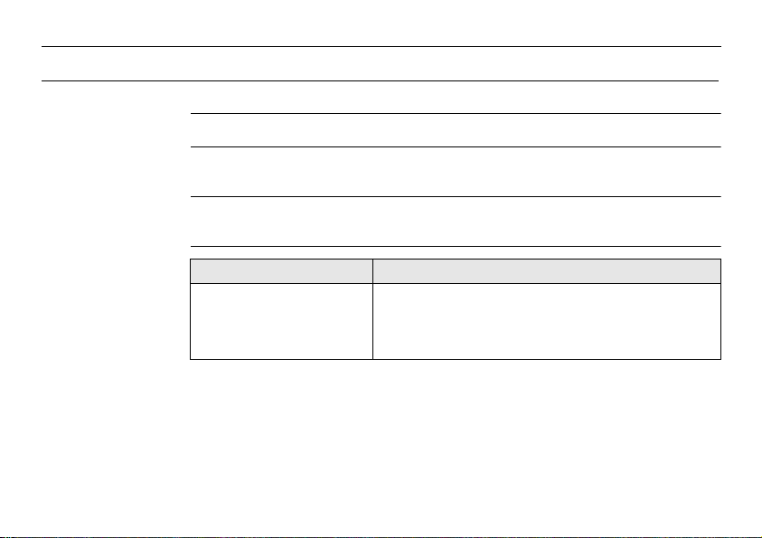
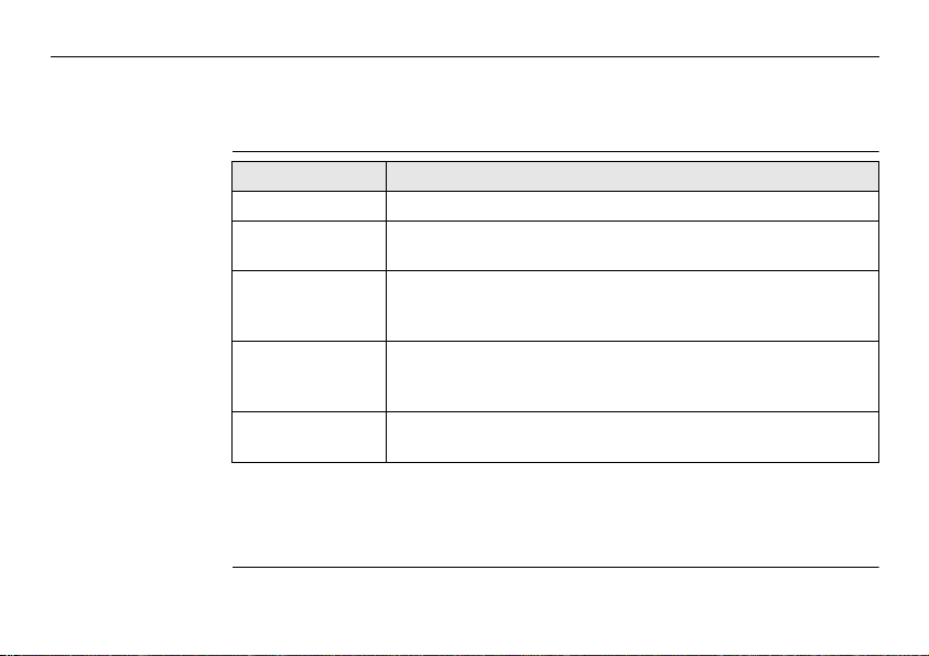
Name of documentation Description
Builder User Manual All instructions required in order to operate the
instrument to a basic level are contained in this User
Manual. Provides an overview of the instrument
together with technical data and safety directions.
Name of documentation Description
Builder Construction made
faster
Builder Quickguide Describes the onboard application programs step-by-
Describes the basic principle of construction measurement in combination with Builder functionality.
step. Intended as a quick reference field guide.
Format of the
documentation
How to Use this Manual Builder 13
The Builder CD contains the entire documentation in electronic format. It is also available in printed form.

Technical Terms and Abbreviations
b
c
c
d
e
f
g
b
c
b
b
a
a
2 Technical Terms and Abbreviations
Terminology
14Builder
Term Description
Line of sight / collimation axis Telescope axis = line from the reticle to the
a)
b) Standing axis Vertical rotation axis of the instrument.
c) Tilting axis Horizontal rotation axis of the telescope.
d) Vertical angle / zenith angle
Vertical circle With coded circular division for reading the
e)
f) Horizontal angle
Horizontal circle With coded circular division for reading the
g)
Technical Terms and Abbreviations Builder 15
centre of the objective.
vertical angle.
horizontal angle.
Technical Terms and Abbreviations
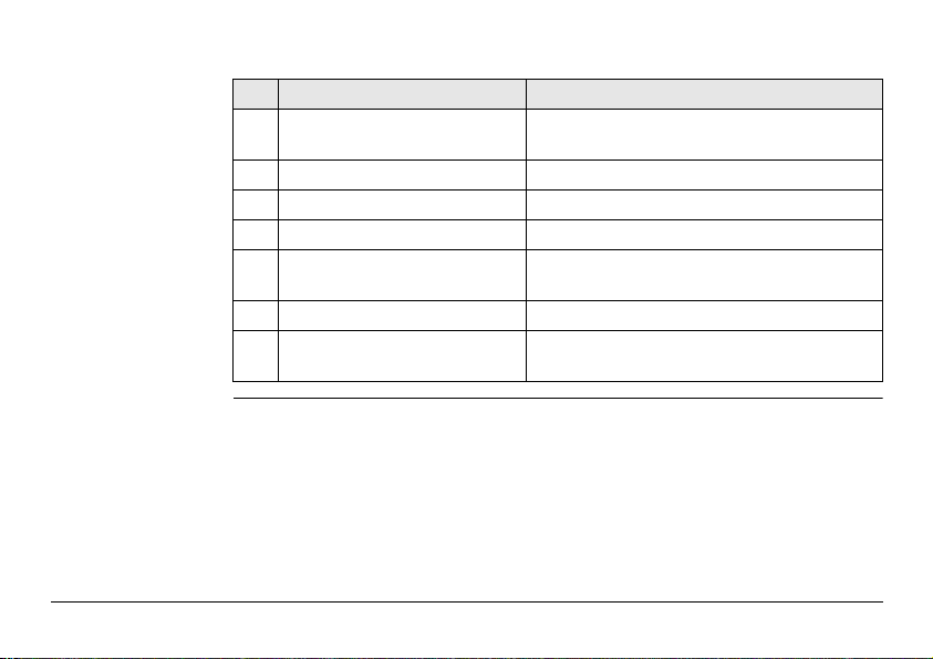
Plumb line /
Compensator
16Builder
Direction of gravity. The compensator defines the plumb
line within the instrument
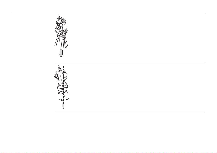
Standing axis inclination
Angle between plumb line and standing axis.
Standing axis tilt is not an instrument error and is not
eliminated by measuring in both faces. Any possible influence it may have on the horizontal direction resp. vertical
angle is eliminated by the dual axis compensator.
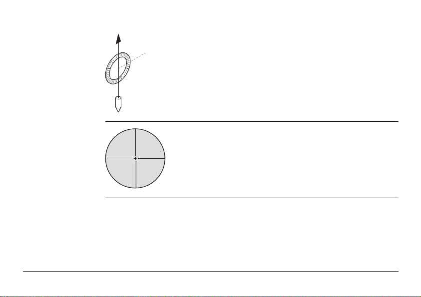
Zenith
Point on the plumb line above the observer.
Reticle
Technical Terms and Abbreviations Builder 17
Glass plate within the telescope with reticle.
Technical Terms and Abbreviations
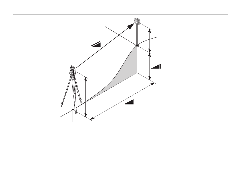
Explanation of
displayed data
E0, N0, H
0
18Builder
E, N, H
hr
hi
Abbreviation Description
Indicated meteorological corrected slope distance between instrument tilting axis and centre of prism/laser dot.
Indicated meteorological corrected horizontal distance.
Height difference between station and target point.
hr Reflector height above ground
hi Instrument height above ground
E
0
N
0
H
0
Easting of Station
Northing of Station
Height of Station
E Easting of target point
N Northing of target point
H Height of target point
Technical Terms and Abbreviations Builder 19
Description of the System
3 Description of the System
3.1 Instrument Models
20Builder
Instrument models
)
Model Description
Builder T Electronic theodolite.
Builder R Electronic theodolite with distance measurement capability and
construction software.
Builder RM Same as Builder R, additionally with RS232 interface and
internal memory to store and manage data and an extended
application menu.
Builder RM power* Same as Builder RM, additionally with 10-digits keypad,
distance measurement with reflectors (fine/fast mode), LED
that shows used EDM mode and an extended application menu.
Builder M power* Same as Builder RM power but only distance measurements
with reflectors (fine/fast mode).
Builder T, R and RM are available as Builder 100 and 200.
Builder RM power is available as Builder 100, 200 and 300.
Builder M power is available as Builder 100 and 200.
*) The term "power" can be abbreviated as "p", for example Builder R300Mp.
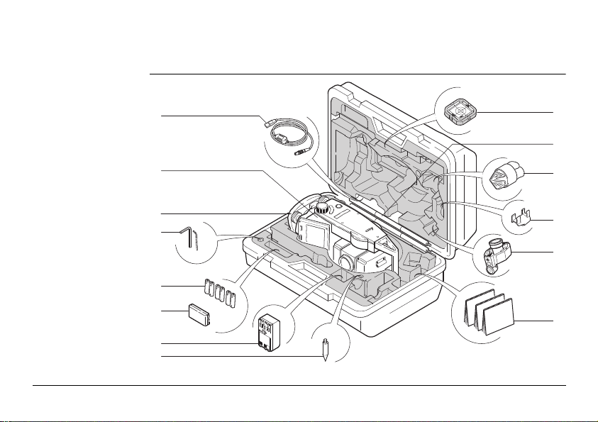
3.2 Set Contents
k
Set contents
a
b
c
d
e
f
g
h
Description of the System Builder 21
i
j
l
m
n

Description of the System
a) GEV189 USB Data transfer cable (for Builder RM)
b) Builder instrument with keyboard
c) CTB101 Tribrach w/o optical plummet, black
d) One Allen key, one Adjusting pin
e) Alkaline batteries, 3x Twinpack, Size AA
f) GEB111 Battery
g) GAD39 battery adapter for Alkaline batteries, Size AA
h) Tip for GLS115
i) CPR105 Double-sided flat prism
j) GLS115 Mini reflector pole set
k) Protective cover / Lens hood
l) GLI115 Clip-on bubble for GLS115
m) CPR111 BUILDER Prism, True-Zero Offset
n) User Manual, CD Rom, Booklet "Construction made faster"
22Builder
)
The content depends on the chosen Builder model.
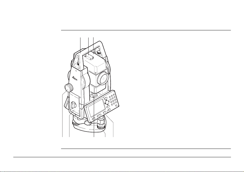
3.3 Instrument Components
abc
edfgh
Instrument components, part 1 of 2
a) Detachable carrying handle with
mounting screws
b) Alignment sight
c) Telescope (with integrated Distance
Meter for R, RM, M power and
RM power)
d) Vertical drive
e) Battery holder for
GAD39/GEB111/GEB121
f) Circular level
g) Tribrach
h) Serial interface RS232 (for Builder RM,
M power and RM power)
Description of the System Builder 23
Description of the System
jikl
onp rqms
Instrument components, part 2 of 2
24Builder
i) Telescope focusing ring
j) Eyepiece
k) Battery GEB111 (optional)
l) Battery stand for GEB111
m) Horizontal drive
n) Foot screw
o) Display
p) Tribrach securing screw
q) Keypad (Keypad depends on model.
Refer to chapter "4.1 Keyboard".)
r) Battery adapter GAD39 for 6 single
cells, Size AA
s) Battery GEB121 (optional)

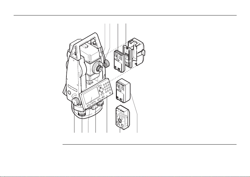
3.4 Power Supply
ab c
Instrument Power for the instrument can be supplied either internally or externally.
Internal battery • Six single cells, Size AA in the battery adapter GAD39,
• or one GEB111 battery,
• or one GEB121 battery
fitted into the battery compartment.
External battery • One GEB171 battery,
• or one GEB70 battery
connected via cable.
Batteries
a) Single cells, Size AA
in the battery
adapter GAD39
b) GEB111
c) GEB121
)
Description of the System Builder 25
Use the Leica Geosystems batteries, chargers and accessories or accessories recommended by Leica Geosystems to ensure the correct functionality of the instrument.
Description of the System
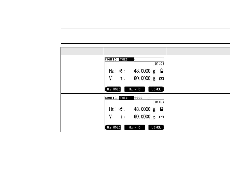
3.5 Software Concept
26Builder
Description All instrument types use the same software concept. The software has different
Software Concept
modes depending on the instrument type.
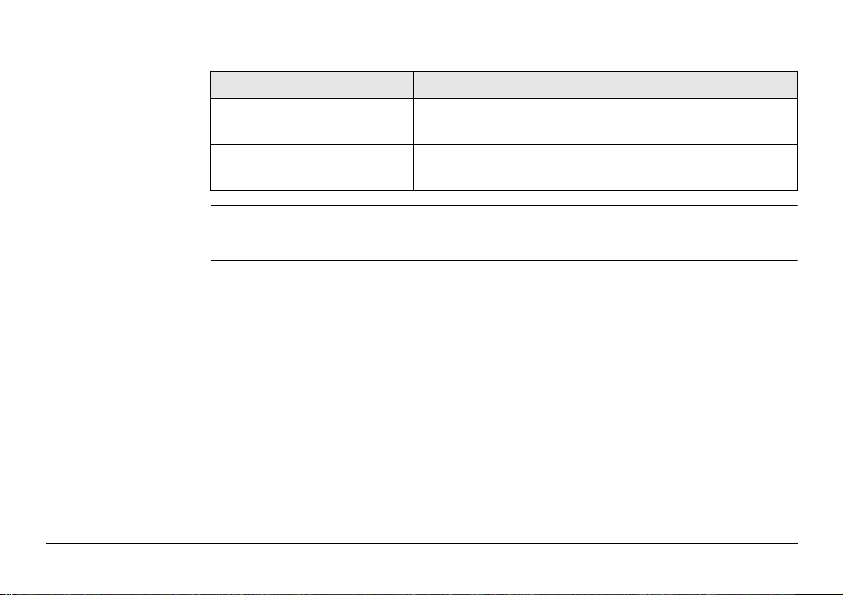
Model Screen Available Modes
Builder T • Configuration Mode
• Theodolite Mode
Builder R • Configuration Mode
• Theodolite Mode
• Programs Mode
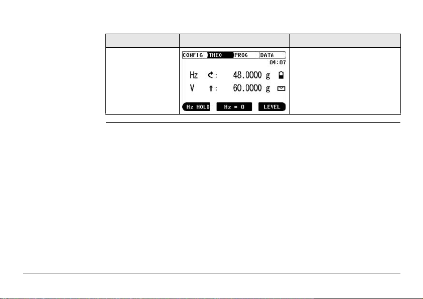
Model Screen Available Modes
Builder RM,
M power and
RM power
Description of the System Builder 27
• Configuration Mode
• Theodolite Mode
• Programs Mode
• Data Management Mode
User Interface
4 User Interface
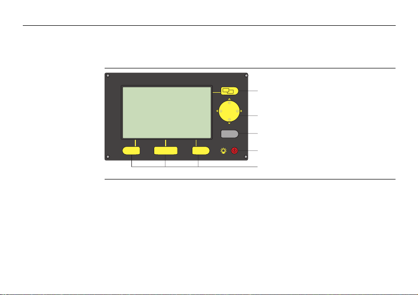
4.1 Keyboard
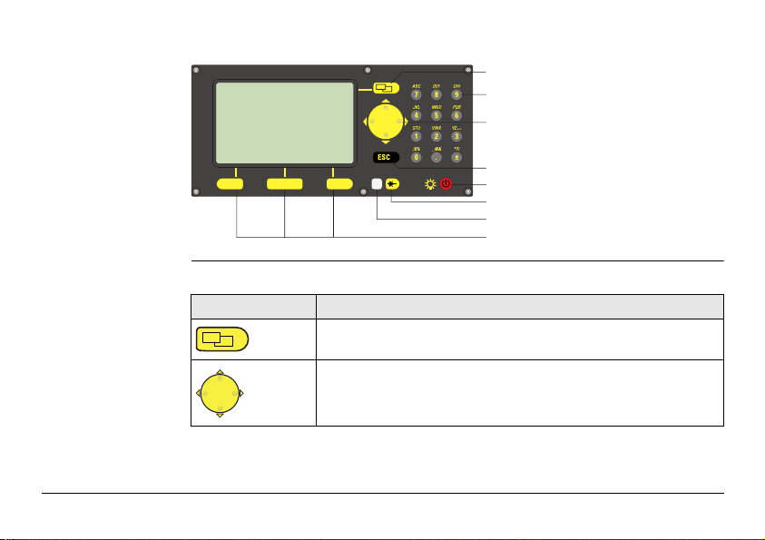
Keyboard
Builder T, R and RM
ESC
a
b
a) Page key
c
b) Navigation keys
c) ESC
d
d) On/Off, Light
e
e) Function keys
28Builder
Keyboard Builder
M power and
RM power
Keys All Builder models:
Key Description
Changes tab in the tab bar.
• Move the focus on the screen
• Start the edit mode for edit fields
• Control the input bar in edit and input mode
User Interface Builder 29
a
b
a) Page key
c
b) 10-digits keypad
c) Navigation keys
d
d) ESC
e
e) On/Off, Light
f
f) EDM key
g
g) LED
h
h) Function keys
User Interface
30Builder
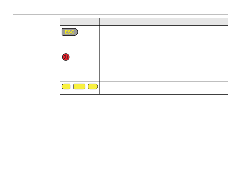
Key Description
• Leaves the current menu or dialog without storing changes
made.
•If THEO mode is active: press approx. 5 seconds to access
System Info.
• If the instrument is off: to turn instrument on
• If the instrument is on:
• press at any time to turn on and off the display light incl.
reticle illumination
• and press approx. 5 seconds to turn off the instrument
Correspond to the three softkeys that appear on the bottom of
the screen when the screen is activated.
 Loading...