

Page 1
INSTRUCTION/INSTALLATION SHEET
V
Speaker Level / Impedance Matching
301 Fulling Mill Road, Suite G
Middletown, PA 17057
Phone (800) 321-2343 / Fax (717) 702-2546
www.onqlegrand.com
olume Control
IS-1507094 REV. O
1. Introduction
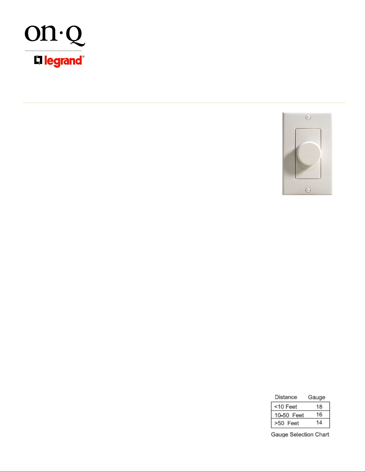
The On-Q/Legrand Speaker Level / Impedance Matching Volume Control, P/N
AU0100-WHDM-V1/AU0100-WHLA-V1 (see Figure 1), is meant to be used in a
multiple speaker distributed sound systems. These volume controls enable more pairs
of speakers to be connected to an amplifier than the amplifier could normally
accommodate (due to impedance matching ability). The impedance matching volume
controls mate perfectly with parallel audio distribution devices such as the On-Q 4 Zone
Audio Distribution Outlet (P/N 364741-xx-V1). The volume control also has a nonimpedance matching (speaker level), (1x) option to accommodate a single pair of
speakers. When used in this fashion optimum fidelity will be achieved with a single pair
of speakers.
2. Description
The On-Q Speaker Level / Impedance Matching Volume Control occupies a single gang of an electrical box and
is offered in white, almond, and light almond in an attractive decorator style. It has wiring blocks that disconnect
for easy wiring and offer impedance matching selection via jumpers labeled 1x, 2x, 4x, and 8x, (1x=nonimpedance matching), located on the circuit board. It is recommended to be installed in a low voltage bracket
such as the On-Q Single Gang Retrofit Low Voltage Bracket (F9060-01-V9), or an electrical box that is 20 cubic
inches or greater in volume.
Figure 1
3. Installation
Installation of the On-Q Speaker Level / Impedance Matching Volume Control is easily accomplished at multiple
times during new construction, at “Rough-in” before the drywall is installed, and at “Trim-out” after the drywall is
installed and painted or at any time following similar procedures for a retrofit opportunity.
NOTE: Before connecting the volume control: Make sure that power is not connected to the
receiver/amplifier that will be driving audio signals to the volume controls. For instructions on pre-wiring
and installing other components of any On-Q Audio System, please see the Instruction Sheets included
with those components.
A. “Rough-in” steps:
1) A single 16/4 speaker wire should be run from the location of the audio distribution device (such as the 4
Zone Audio Distribution Outlet) to a single gang outlet box or low voltage bracket at each Volume Control
location.
Note: It is recommended that a minimum of 16 gauge 4 conductor
wire be run for most applications from the audio distribution device
to the volume control. Different gauge wire can, and should, be
used based upon the distance of the intended run or quality of
installation (see Figure 2) . It is recommended that wire gauge not
be less than 18 gauge. The impedance matching volume control can
Figure 2
Page 1 of 3
©Copyright 2009 by On-Q/Legrand All Rights Reserved.
Page 2
INSTRUCTION/INSTALLATION SHEET
V
Speaker Level / Impedance Matching
301 Fulling Mill Road, Suite G
Middletown, PA 17057
Phone (800) 321-2343 / Fax (717) 702-2546
www.onqlegrand.com
olume Control
accommodate up to 14 gauge wire.
2) A single 16/2 speaker wire should be run from each speaker location to the outlet box or low voltage
bracket at the volume control location.
B. “Trim-out” steps:
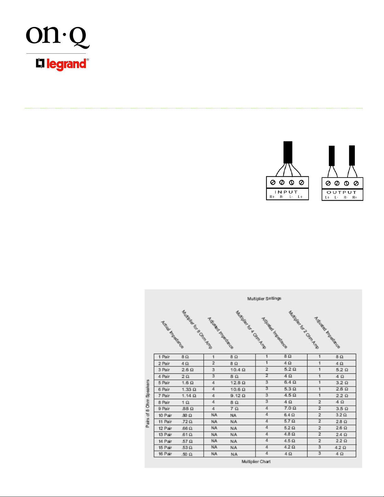
1) Strip 3/16ths of an inch from all conductors (feed from distribution and
runs to speakers) and insert the wires into the wiring blocks (see
Figure 3) of the volume control.
2) Tighten screws onto wire and give them a tug to insure they are
properly fastened.
NOTE: BE SURE NOT TO REVERSE THE AMPLIFIER OR SPEAKER
CONNECTIONS OR DAMAGE TO THE AMPLIFIER COULD RESULT!
3) Install the volume control into the low voltage bracket/electrical box.
4) Determine how many pairs of speakers will be powered by the same amplifier (in parallel).
5) Determine the speaker output impedance or ohm capability of the amplifier (typically 8 ohms, 4 ohms or 2
ohms). This will be listed in the specification of the amplifier. It yields how "low" of a load the amplifier can
safely run before damage or over heating occurs.
NOTE: Impedance varies with
frequency, so in actuality, no
load is seen as a constantly
stable (8, 4 or 2 ohms), it
varies as frequency varies.
(This is why some of the
higher selections were made
in the Multiplier chart.),(see
Figure 4).
NOTE: This chart refers to 8
ohm speakers. If the Speakers
being used are some other
impedance, you must
calculate the parallel
impedance and multiply it by
the appropriate multiplier (X2,
X4 or X8), see Figure 4, to
match the load to the
amplifier’s capabilities. Nonimpedance matching=X1 (see
Figure 5 for the formula to
calculate impedance).
IS-1507094 REV. O
Figure 3
Figure 4
Page 2 of 3
©Copyright 2009 by On-Q/Legrand All Rights Reserved.
Page 3
INSTRUCTION/INSTALLATION SHEET
V
Speaker Level / Impedance Matching
301 Fulling Mill Road, Suite G
Middletown, PA 17057
Phone (800) 321-2343 / Fax (717) 702-2546
www.onqlegrand.com
olume Control
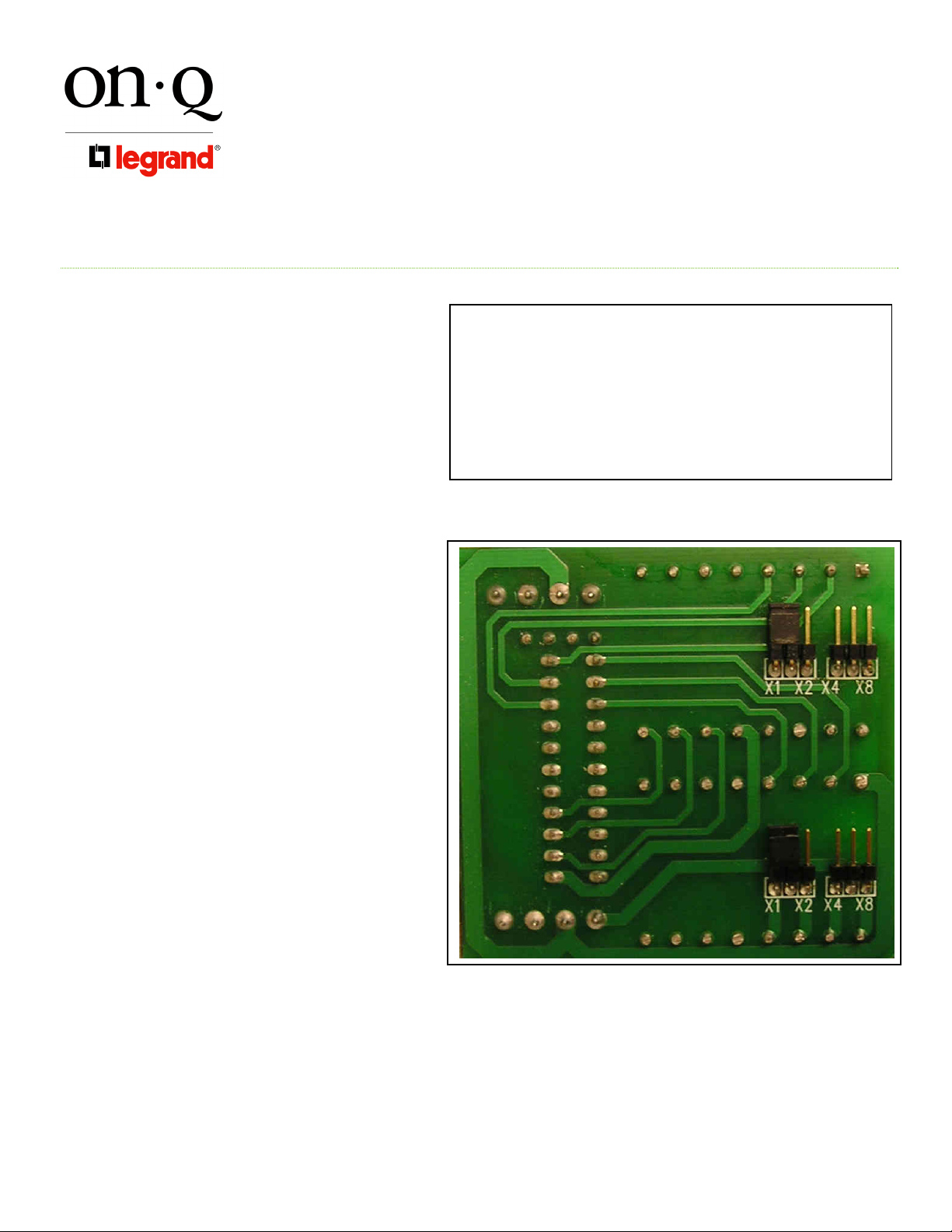
6) After load capacity is determined, refer
to Figure 4 to determine the proper
multiplier setting for all the volume
controls.
NOTE: Multiplier setting #1 refers to
jumper position X1, multiplier setting #2
refers to jumper position X2, multiplier
setting #3 refers to jumper position X4
and multiplier setting 4 refers to jumper
position X8 (see Figure 6).
7) Position the jumper plug on the two
pins relating to the appropriate
multiplier setting (X1, X2, X4, or X8)
see Figure 6).
NOTE: Although there are jumpers for
each speaker’s output, in most cases
they will be set exactly the same.
NOTE: Rotating the volume control fully
counter clockwise will yield no power
going to the speakers (off).
C. To change color:
1) Pull off knob.
2) Unscrew coverplate.
3) Unsnap inner cover.
4) Snap on new inner cover.
5) Screw on new coverplate.
6) Push on new knob.
IS-1507094 REV. O
Formula for calculating impedance of parallel speakers:
1/x ohms + 1/x ohms = 1/y impedance
1/8 ohms + 1/8 ohms = 2/8 ohms or 1/ 4 ohms
(2 - 8 ohm speakers in parallel exhibit 4 ohms of impedance)
NOTE: Speakers wired in series exhibit purely additive
impedance (8+8 + 16).
Figure 5
Figure 6
Page 3 of 3
©Copyright 2009 by On-Q/Legrand All Rights Reserved.
Page 4

FEUILLET D’INSTRUCTION ET
D’INSTALLATION
Commande de volume adaptant l’impédance et le
301 Fulling Mill Road, Suite G
Middletown, PA 17057
Téléphone (800) 321-2343/Télécopieur (717) 702-2546
www.onqlegrand.com
1. Présentation
La commande pour haut-parleurs On-Q/Legrand adaptant le niveau sonore et l’impédance,
numéro de pièce AU0100-WHDM-V1/AU0100-WHLA-V1 (voir Figure 1) est conçue pour être
utilisée avec des chaînes stéréophoniques à plusieurs haut-parleurs. Ces commandes de
volume permettent de brancher plus de haut-parleurs sur un amplificateur qu’il ne serait
normalement possible de le faire (en raison de la capacité à adapter l’impédance). Les
commandes de volume adaptant l’impédance conviennent parfaitement à des appareils de
distribution audio parallèles comme les prises de distribution audio On-Q 4 Zone (numéro de
pièce 364741-xx-V1). La commande sonore est également dotée d’un réglage non adapté à
l'impédance (niveau sonore du haut-parleur), (1x) qui peut servir lorsqu'une seule paire de hautparleurs est utilisée. Une restitution sonore optimale peut alors être obtenue.
2. Description
La commande pour haut-parleurs On-Q/Legrand adaptant le niveau sonore et l’impédance occupe une seule prise
de la boîte électrique. Elle est offerte en blanc, amande et amande claire dans un style décoratif attrayant. Elle est
dotée de blocs de connexion qui peuvent être débranchés pour faciliter le câblage. Elle offre également une
sélection d’adaptation d’impédance grâce à des cavaliers identifiés par les symboles 1x, 2x, 4x et 8x, (1x
correspondant à l’absence d’adaptation de l’impédance), située sur la carte de circuits imprimés. Il est recommandé
d’installer un support basse tension comme un support basse tension à prise unique On-Q à installation après coup
(F9060-01-V9), ou une boîte électrique dont le volume cubique est d’au moins 20 pouces (327 cm).
3. Installation
Il est facile d’installer la commande pour haut-parleurs On-Q adaptant le niveau sonore et l’impédance à plusieurs
moments lors d’une nouvelle construction. Il est notamment possible de le faire lors de la pose de la charpenterie
brute avant que les cloisons sèches ne soient installées et lors des travaux de menuiserie de finition une fois les
cloisons sèches posées et peintes ou à tout autre moment pour une pose après coup.
REMARQUE : Avant le branchement de la commande de réglage du volume : Assurez-vous que le
récepteur/amplificateur qui transmet les signaux audio aux commandes sonores n'est pas alimenté en
courant. Pour des directives sur le précâblage et l’installation d’autres composants d’un système On-Q
Audio, veuillez consulter la notice accompagnant ces pièces.
A. Étapes à suivre (si la commande est posée lors des travaux de charpenterie brute) :
1) Un fil pour haut-parleur simple 16/4 doit être acheminé de l’endroit où se trouve l’appareil de distribution
audio (comme une prise de distribution audio à quatre zones) jusqu’à une prise simple d'une boîte
électrique ou un support basse tension pour chaque emplacement de commande de volume.
Remarque : Il est recommandé d'utiliser un fil conducteur de calibre 16 à
quatre brins utilisé pour la plupart des applications. Ce fil doit relier l'appareil
de distribution audio à la commande de réglage du volume. Des fils de
différents calibres peuvent et doivent être utilisés. La distance parcourue par
le fil et la qualité de l'installation sont des facteurs à considérer lors du choix
de fil (voir Figure 2). Un fil d’un calibre inférieur à 18 ne devrait pas être utilisé.
La commande de volume à adaptation de l’impédance peut accueillir des fils
niveau sonore
IS-1507094 RÉV. O
Figure 1
Figure 2
Page 1 of 3
©Copyright 2009 by On-Q/Legrand All Rights Reserved.
Page 5

FEUILLET D’INSTRUCTION ET
D’INSTALLATION
Commande de volume adaptant l’impédance et le
301 Fulling Mill Road, Suite G
Middletown, PA 17057
Téléphone (800) 321-2343/Télécopieur (717) 702-2546
www.onqlegrand.com
d'un calibre maximal de 14.
2) Un fil de haut-parleur 16/2 doit être acheminé des endroits où se trouvent les haut-parleurs jusqu’à la boîte
de branchement ou jusqu’au support basse tension de la commande de volume.
B. Étapes à suivre (si la commande est posée lors des travaux de menuiserie de finition) :
1) Dénudez 3/16 de pouce de tous les conducteurs (partant de l’appareil de
distribution jusqu’aux haut-parleurs) et insérez les fils dans les blocs de
câblage de la commande du volume (voir la Figure 3).
2) Serrez les vis sur le fil et vérifiez le serrage pour vous assurer qu'ils sont
correctement fixés.
REMARQUE : ASSUREZ-VOUS DE NE PAS INVERSER LES CONNEXIONS DE L’AMPLIFICATEUR ET DU
HAUT-PARLEUR SANS QUOI DES DOMMAGES POURRAIENT SURVENIR!
3) Installez la commande de volume sur le support basse tension/dans la boîte électrique.
4) Déterminez combien de paires de haut-parleurs seront alimentées par le même amplificateur (en parallèle).
5) Déterminez l'impédance de sortie du haut-parleur ou la capacité en ohms de l'amplificateur (généralement
8 ohms, 4 ohms ou 2 ohms). Cette information se trouve dans les spécifications de l’amplificateur. Elle
indique la charge minimale qu’un amplificateur peut supporter sans risque de dommages ou de surchauffe.
REMARQUE : L'impédance varie en
fonction de la fréquence. Par
conséquent, aucune charge n'est
toujours stable (8, 4 ou 2 ohms). Elle
varie proportionnellement à la
fréquence. (Voilà pourquoi certaines
des sélections supérieures ont été
placées dans le tableau de
multiplication.), (voir la Figure 4).
REMARQUE : Ce tableau se base sur
des haut-parleurs de 8 ohms. Si les
haut-parleurs utilisés ont une autre
impédance, vous devez calculer
l’impédance parallèle et la multiplier
par le multiplicateur approprié (X2,
X4 ou X8), voir la Figure 4, pour
adapter l’impédance aux capacités de
l’amplificateur. Réglage non adapté à
l’impédance = X1 (reportez-vous à la
Figure 5 pour trouver la formule
servant à calculer l’impédance.)
niveau sonore
IS-1507094 RÉV. O
Figure 3
Figure 4
Page 2 of 3
©Copyright 2009 by On-Q/Legrand All Rights Reserved.
Page 6

FEUILLET D’INSTRUCTION ET
D’INSTALLATION
Commande de volume adaptant l’impédance et le
301 Fulling Mill Road, Suite G
Middletown, PA 17057
Téléphone (800) 321-2343/Télécopieur (717) 702-2546
www.onqlegrand.com
6) Après avoir déterminé la capacité de la
charge, reportez-vous à la Figure 4
pour trouver le réglage multiplicateur
convenant à toutes les commandes de
volume.
REMARQUE : Le réglage du
multiplicateur n
cavalier X1, le réglage du multiplier n
désigne la position du cavalier X2, le
réglage du multiplicateur n
position du cavalier X4 et le réglage du
multiplicateur n
cavalier X8 (voir la Figure 6).
7) (Placez la fiche de cavalier sur les
deux tiges appropriées correspondant
au réglage de multiplicateur approprié
— x1, x2, x4, x8 ou x16 — qui identifie
la mise à l’échelle verticale de la
courbe.
REMARQUE : Bien que chaque sortie de
haut-parleur comporte un cavalier
propre, tous les cavaliers sont
habituellement placés au même réglage.
REMARQUE : Le fait de tourner
complètement la commande de volume
dans le sens contraire aux aiguilles d'une
montre coupe le courant alimentant les
haut-parleurs (hors fonction).
C. Pour changer la couleur :
1) Retirez le bouton.
2) Dévissez le coverplate.
3) Unsnap la couverture intérieure.
4) Rupture sur la nouvelle couverture intérieure.
5) Vis sur le nouveau coverplate.
6) Poussez sur le nouveau bouton.
niveau sonore
o
1 désigne la position du
o
3 désigne la
o
4 désigne la position du
IS-1507094 RÉV. O
Formule servant à calculer l'impédance de haut-parleurs
parallèles :
1/x ohm + 1/x ohm = 1/y impédance
1/8 ohm + 1/8 ohm = 2/8 ohm ou 1/ 4 ohm
(Haut-parleurs de 2 à 8 ohms en parallèle présentant une
impédance de 4 ohms)
o
2
REMARQUE : Les haut-parleurs câblés en série
présentent une impédance purement additive (8+8 +16).
Figure 5
Figure 6
Page 3 of 3
©Copyright 2009 by On-Q/Legrand All Rights Reserved.
Page 7

HOJA DE INSTALACIÓN E INSTRUCCIONES
Control de volumen para la adaptación de
impedancia y el nivel del altavoz
301 Fulling Mill Road, Suite G
Middletown, PA 17057
Teléfono (800) 321-2343 / Fax (717) 702-2546
www.onqlegrand.com
1. Introducción
El control de volumen para la adaptación de impedancia y el nivel del altavoz OnQ/Legrand P/N AU0100-WHDM-V1/AU0100-WHLA-V1 (ver Figura 1) está diseñado
para sistemas de sonido distribuidos en altavoces múltiples. Estos controles de
volumen permiten la conexión de más pares de altavoces a un amplificador que la que
se puede establecer normalmente (debido a la capacidad de adaptación de
impedancia). Los controles de volumen para la adaptación de impedancia coinciden
perfectamente con los dispositivos paralelos de distribución de audio como la salida de
distribución de audio On-Q Zona 4 (P/N 364741-xx-V1). El control de volumen también
ofrece la opción de no adaptación de impedancia (1x) (nivel del altavoz) que se adapta
a un solo par de altavoces. Cuando se lo utiliza de este modo, se alcanza una fidelidad
óptima con un solo par de altavoces.
2. Descripción
El control de volumen para la adaptación de impedancia y el nivel del altavoz ocupa una salida simple de la caja
eléctrica y se encuentra disponible en blanco, almendra y almendra claro en un atractivo estilo decorativo.
Contiene bloques de cableado que se desconectan para realizar un cableado fácilmente y permite la selección
de la adaptación de impedancia por medio de puentes de conexión etiquetados 1x, 2x, 4x y 8x (1x=no adaptación
de impedancia) ubicados en el tablero de circuito. Se recomienda que se instale a un soporte de bajo voltaje
como el soporte de montaje ajustable de bajo voltaje y salida simple (F9060-01-V9) o una caja eléctrica de 20
pulgadas cúbicas o de mayor volumen.
3. Instalación
La instalación del control de volumen para la adaptación de impedancia y el nivel del altavoz se lleva a cabo
fácilmente en varias etapas durante la construcción nueva en la etapa de “preparación”, antes de que se instale el
panel de yeso y en la etapa de “pulido”, luego de que se instale y se pinte o en cualquier momento después de
que se realice la readaptación en procedimientos similares.
NOTA: Antes de conectar el control de volumen: asegúrese de que la electricidad no esté conectada al
receptor/amplificador que envía señales de audio a los controles de volumen. Para realizar el
precableado y la instalación de otros componentes en todos los sistemas de audio On-Q, consulte las
hojas de instrucciones incluidas en esos componentes.
A. Pasos de “preparación”:
1) El cable simple de 16/4 del altavoz debe ir desde el lugar donde se encuentra el dispositivo de distribución
de audio (como la salida de distribución de audio de Zona 4) hasta una caja de distribución de salida
simple o hasta el soporte de montaje de bajo voltaje en cada lugar donde se encuentra el control de
volumen.
Nota: se recomienda que se pase un cable calibre 16/4 mínimo para
la mayoría de las aplicaciones desde el dispositivo de distribución
de audio hasta el control de volumen. Se puede y se debe utilizar
IS-1507094 REV. O
Figura 1
Página 1 de 3
©Copyright 2009 por On-Q/Legrand Todos los derechos reservados.
Figura 2
Page 8

HOJA DE INSTALACIÓN E INSTRUCCIONES
Control de volumen para la adaptación de
impedancia y el nivel del altavoz
301 Fulling Mill Road, Suite G
Middletown, PA 17057
Teléfono (800) 321-2343 / Fax (717) 702-2546
www.onqlegrand.com
un cable de diferente calibre según la distancia del tramo previsto o
de la calidad de la instalación (ver Figura 2). Se recomienda que el
calibre del cable no sea menor de 18. Para el control de volumen
para la adaptación de impedancia se puede utilizar hasta un cable
de calibre 14.
2) El cable simple de 16/2 del altavoz debe ir desde el lugar donde se encuentra cada altavoz hasta la caja
de distribución o hasta el soporte de bajo voltaje donde se encuentra el control de volumen.
B. Pasos de “pulido”:
1) Retire 0,5 cm de todos los conductores (conecte desde la distribución
hasta los altavoces) e inserte los cables en los bloques de cableado
(ver Figura 3) del control de volumen.
2) Ajuste los tornillos al cable y déles un tirón para asegurarse de que
estén correctamente sujetados.
NOTA: ASEGÚRESE DE NO INVERTIR LAS CONEXIONES DEL AMPLIFICADOR Y DEL ALTAVOZ
PORQUE PODRÍA DAÑAR EL AMPLIFICADOR.
3) Instale el control de volumen en el soporte de bajo voltaje o en la caja eléctrica.
4) Determine cuántos pares de altavoces se enchufarán al mismo amplificador (de forma paralela).
5) Determine la capacidad de ohmios o de impedancia de salida de los altavoces del amplificador
(normalmente 8 ohmios, 4 ohmios o 2 ohmios). Esto estará indicado en las especificaciones del
amplificador. Es necesario saber cuál es la menor carga que el amplificador puede resistir antes de que
se produzca algún daño o sobre calentamiento.
NOTA: La impedancia varía con la
frecuencia así que en realidad,
ninguna carga es constantemente
estable (8, 4 ó 2 ohmios). Esta varía
según varíe la frecuencia. (Es por
esto que en el cuadro multiplicador
se hicieron algunas de las
selecciones más altas. Ver Figura 4).
NOTA: Este cuadro hace referencia a
altavoces de 8 ohmios. Si los
altavoces que se utilizan tienen otra
impedancia, debe calcular la
impedancia paralela y multiplicarla
por el multiplicador correspondiente
(X2, X4 o X8) (ver Figura 4) para que
coincida la carga con la capacidad
del amplificador. No adaptación a
IS-1507094 REV. O
Figura 3
Figure 4
Página 2 de 3
©Copyright 2009 por On-Q/Legrand Todos los derechos reservados.
Page 9

HOJA DE INSTALACIÓN E INSTRUCCIONES
Control de volumen para la adaptación de
impedancia y el nivel del altavoz
301 Fulling Mill Road, Suite G
Middletown, PA 17057
Teléfono (800) 321-2343 / Fax (717) 702-2546
www.onqlegrand.com
impedancia=X1 (consulte la Figura 5
para calcular la impedancia).
6) Luego de que se determinó la
capacidad de carga, consulte la Figura
4 para determinar el ajuste correcto de
los multiplicadores para todos los
controles de volumen.
NOTA: El ajuste del multiplicador Nº 1
hace referencia a la ubicación del
conector X1, el ajuste del multiplicador
Nº 2 hace referencia a la ubicación del
conector X2, el ajuste del multiplicador
Nº 3 hace referencia a la ubicación del
conector X4 y el ajuste del multiplicador
Nº 4 hace referencia a la ubicación del
conector X8 (ver Figura 6).
7) Coloque el enchufe del puente de
conexión en las dos clavijas teniendo
en cuenta el ajuste apropiado del
multiplicador (X1, X2, X4 o X8) (ver
Figura 6).
NOTA: Aunque hay puentes de conexión
para cada salida de los altavoces, en la
mayoría de los casos serán exactamente
los mismos.
NOTA: Si se gira el control de volumen
completamente en sentido antihorario no
llegará electricidad a los altavoces
(apagado).
C. Para cambiar color:
1) Arranque la perilla.
2) Desatornille el coverplate.
3) Unsnap la cubierta interna.
4) Broche de presión en la nueva cubierta interna.
5) Tornillo en nuevo coverplate.
6) Empuje en nueva perilla.
IS-1507094 REV. O
Fórmula para calcular la impedancia de los parlantes
paralelos:
1/x ohmios + 1/x ohmios = 1/y de impedancia
1/8 ohmios + 1/8 ohmios = 2/8 ohmios o 1/ 4 ohmios
(Los altavoces de 2 - 8 ohmios en paralelo presentan 4
ohmios de impedancia)
Figura 5
Figura 6
Página 3 de 3
©Copyright 2009 por On-Q/Legrand Todos los derechos reservados.
 Loading...