

Page 1
Radio system
on ZigBee
®
technology
ARTEOR TECHNICAL GUIDE
RADIO SYSTEM ON ZigBee
®
TECHNOLOGY
Page 2
Radio system
on ZigBee
®
technology
General features ........................................ IV-02
Wiring diagrams ......................................... IV-26
Page 3
IV-2
RADIO SYSTEM ON ZigBee® TECHNOLOGY
GENERAL FEATURES
Introduction to the Radio system
on ZigBee
®
technology
The Radio system is particularly suitable for medium-sized
installations and for refurbishments.
Making the system does not involve special masonry work
and allows future expansions.
The Radio Legrand ZigBee
®
System uses the ZigBee®
transmission technology based on the IEEE 802.15.4 standard
for Wireless personal area network (WPAN).
This international communication standard works on the
frequency of 2.4 GHz.
The ZigBee
®
protocol is particularly suitable for HOME
AUTOMATION applications because it features simplicity of
management and safety for the people using it.
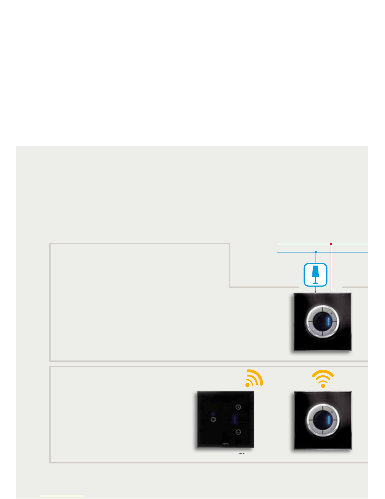
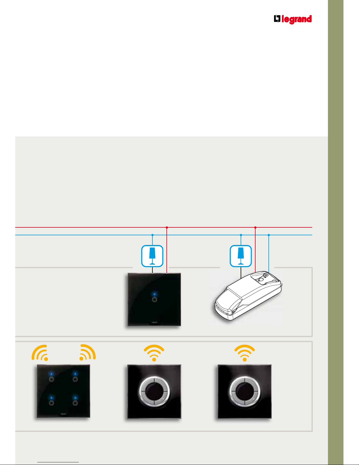
ACTUATORS
RADIO CONTROLS
Connected to the load and the electrical mains
(receiving and transmitting devices).
Battery power supplies
(transmitting devices).
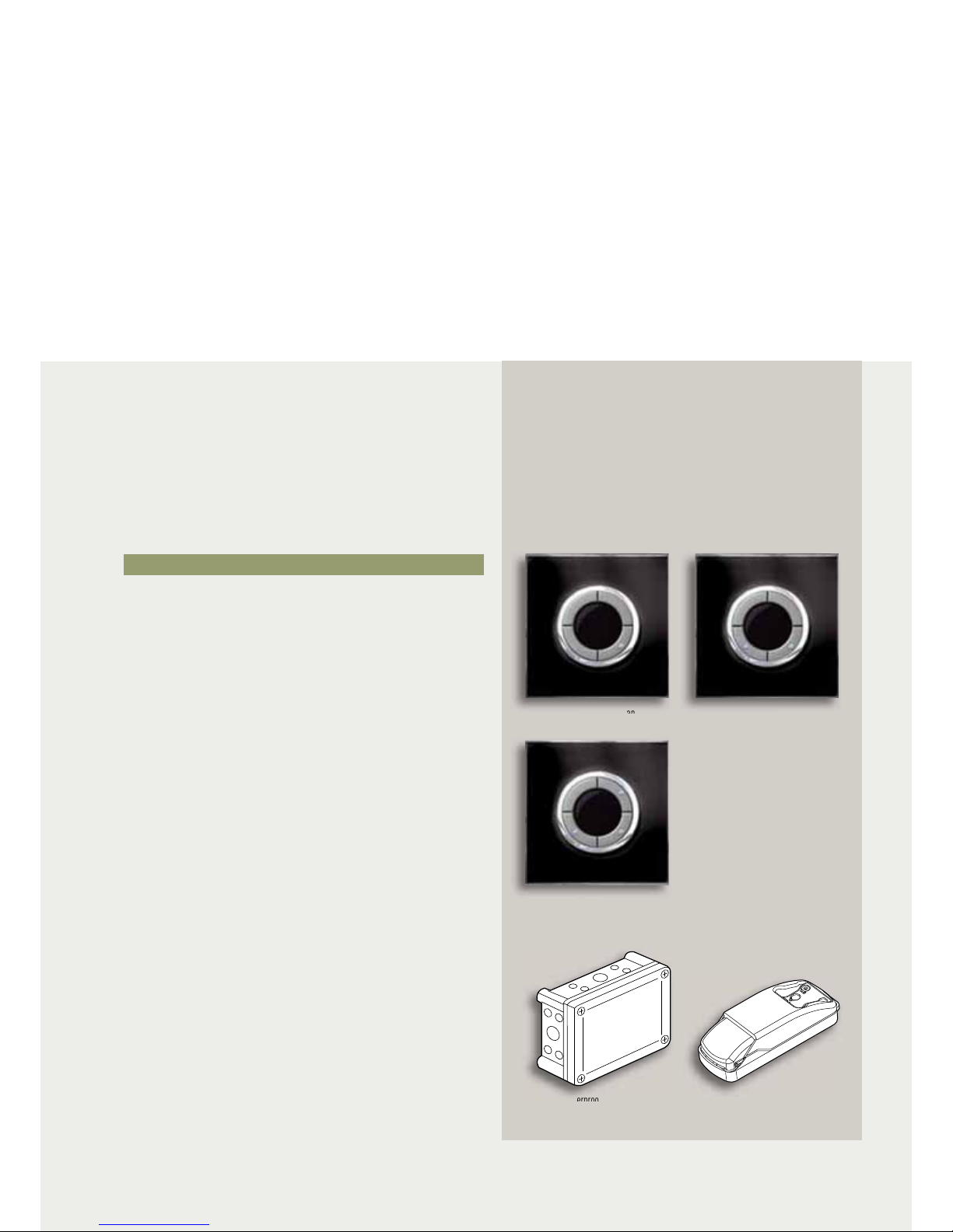
Dimmer control
with touch plate
Dimmer control
Dimmer
B
D
Dimmer
Page 4
IV-3
ARTEOR TECHNICAL GUIDE
RADIO SYSTEM ON ZigBee
®
TECHNOLOGY
The advantages of the installation of the Radio system on
ZigBee
®
technology:
PLUG and PLAY installation
No dedicated wiring (can use already existing wiring)
No specific software
“Intelligence” integrated in the device
Configuration with PUSH and LEARN procedure directly on
the device
4 Scenarios control Switch control Switch control
Switch
Integration module
L
E
R
A
NE
Page 5
IV-4
RADIO SYSTEM ON ZigBee® TECHNOLOGY
GENERAL FEATURES
Inside the Radio system Legrand ZigBee® System there are
two types of device:
Devices connected to the load or switch
Control-only devices
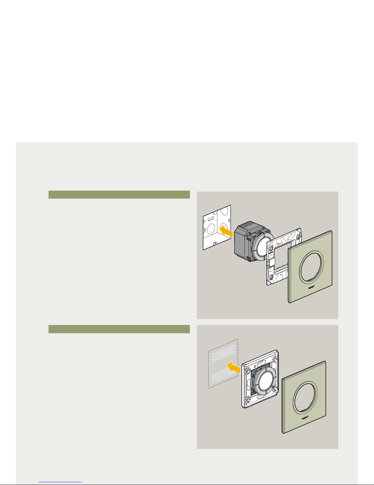
DEVICES CONNECTED TO THE LOAD
The devices connected to the load must be installed in flushmounted boxes and connected to the 240 V a.c. electrical
mains and to the load to be controlled.
These devices receive the commands sent to them and send
the commands to other devices.
CONTROL-ONLY DEVICES
These devices are installed on the wall in any point of the
home or office. They are battery supplied and send the
commands to the “connected to the load” devices associated
to them.
Wall installation without masonry work
Installation in flush-mounted boxes
Introduction to the Radio system
on ZigBee
®
technology
Page 6
IV-5
ARTEOR TECHNICAL GUIDE
RADIO SYSTEM ON ZigBee
®
TECHNOLOGY
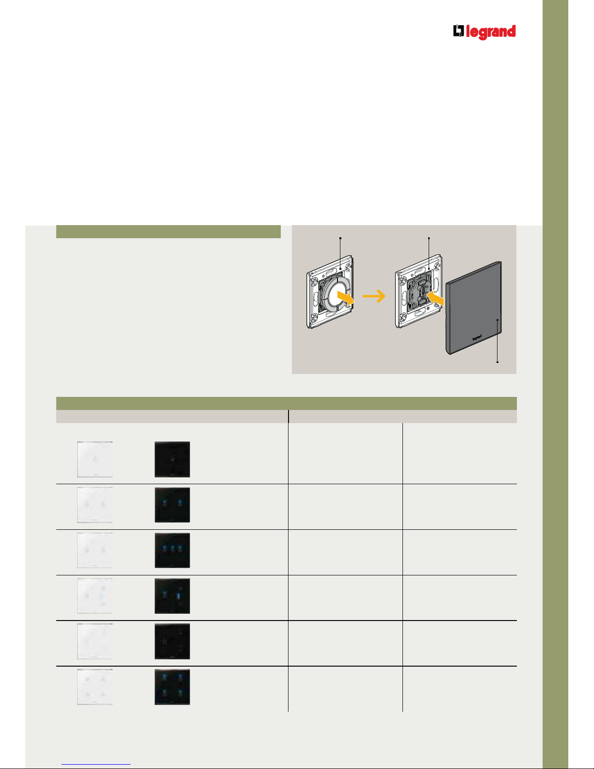
Customisation
with touch plates
Touch plates can be installed to customise the switches and
radio controls. They must replace the control keys already on
the devices.
DEDICATED DEVICE COVERS
Touch plate – radio device association table
Touch plate Switch Radio controls
White Black
For 1-CHANNEL
switches
xx
For 2-CHANNEL
switches
xx
For 3-CHANNEL
switches
x-
For 1-CHANNEL
dimmers
xx
For shutters
xx
For scenarios
-x
Touch plate
Radio control
Remove the
control keys
Install the
touch plate
Radio control
Page 7
IV-6
RADIO SYSTEM ON ZigBee® TECHNOLOGY
GENERAL FEATURES
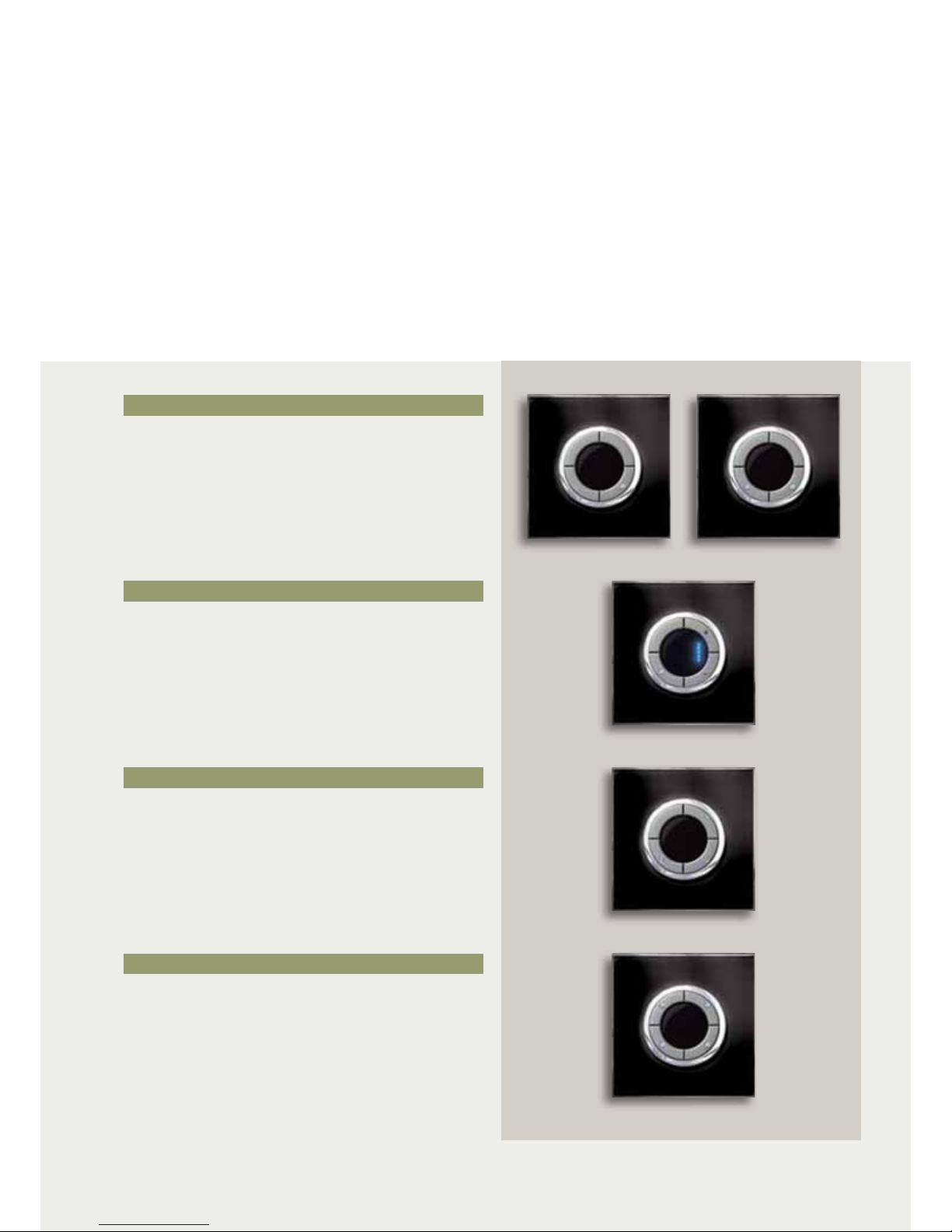
These devices can:
Control the switches associated to them
Devices to manage 4-scenarios.
CONTROL SWITCHES
Dimming control 1 gang
4-scenario control
-
Controls
The following belong to this category:
1 or 2-channel devices to control the switching ON/OFF
of loads.
1-channel devices to control the switching ON/OFF and adjust
the brightness of luminous loads.
DIMMING CONTROL
SHUTTER CONTROL
The radio controls are not directly connected to the load.
4-SCENARIO CONTROL
1-channel devices to control the shutters.
Can call the PRESET position saved in the Shutter switch
associated to it.
Switch control 1 gang
Switch control 2 gang
Shutter control
Page 8
IV-7
ARTEOR TECHNICAL GUIDE
RADIO SYSTEM ON ZigBee
®
TECHNOLOGY
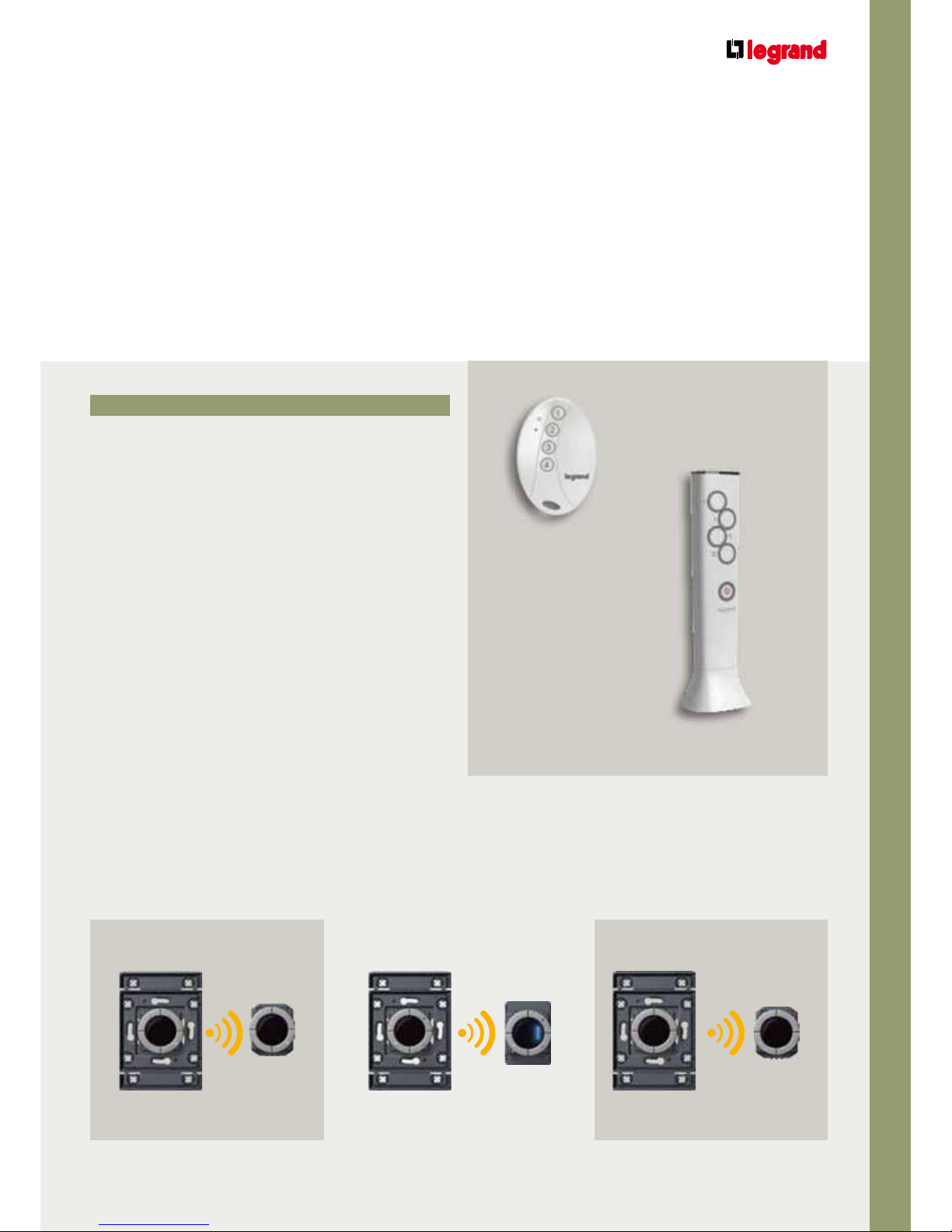
REMOTE CONTROLS
The radio commands must be associated to their switch with the “PUSH and LEARN” procedure.
Switch Dimmer Shutter
switch
Pocket remote control
To control 4 devices or call 4-scenarios.
Advanced RF and IR remote control
To call 5 scenarios and send general commands.
The remote control works both in RF and with IR transmission.
Pocket remote control
Advanced RF and IR remote control
Switch control Dimming control Shutter control
Page 9
IV-8
RADIO SYSTEM ON ZigBee® TECHNOLOGY
GENERAL FEATURES
Switches and dimmers
These devices can:
Control the load connected to them
Send commands to other devices associated to them
Receive commands from the controls and from other
switches and dimmers associated to them
Switches and dimmers are directly connected to the load to be controlled and to the 240 V a.c.
electrical mains.
Switches without neutral with LED status
Can control 100 – 240 V a.c. loads with max power 300 W.
Switches with neutral with LED status
Can control 100 – 240 V a.c. loads with max power 2500 W,
2 x 1000 W or 3 x 1000 W.
Waterproof switch
To control loads up to 1 x 2500 W or 2 x 2500 W.
Can be installed outside.
Integration module switch
To control loads up to 2500 W.
To be used for installations in ceilings.
SWITCHES
The following belong to this category:
Switch 300 W and 2500 W
Switch 2 x 1000 W
Switch 3 x 1000 W
L
E
R
A
NE
Waterproof switch 1 x 2500 W
and 2 x 2500 W
Integration module switch 2500 W
Page 10

IV-9
ARTEOR TECHNICAL GUIDE
RADIO SYSTEM ON ZigBee
®
TECHNOLOGY
DIMMERS
To the load dimmer without neutral with
bargraph LED
Can control and adjust 100 – 240 V a.c. loads with max power
300 W or 600 W.
Universal dimmer with neutral
Can control and adjust 100 – 240 V a.c. loads with max power
300 W.
Dimmer with bargraph LED
For 0 – 10 V ballast.
Integration module
To control loads up to 600 W or ballast.
To be used for installations in ceilings.
SHUTTERS SWITCH
LE
R
A
NE
LE
R
A
NE
Dimmer whit bargraphe LED
Universal dimmer
Shutter switch
To control shutters.
Integration module dimmer
600 W
Integration module dimmer
for ballast
Page 11

IV-10
RADIO SYSTEM ON ZigBee® TECHNOLOGY
GENERAL FEATURES
Interfaces
TRANSCEIVER for technical alarm
When a flooding or gas leak alarm is given it transmits a
technical alarm.
RELAY for technical alarm
When a technical alarm is received it closes a valve attached
to it and may activate a signal (audible/sound).
Transceiver for technical alarm
Relay for technical alarm
Relay for technical alarm
Transceiver for technical alarm
Technical
alarm
GAS leak or
flooding alarm
Closes
Activates sound
signalling
Page 12

IV-11
ARTEOR TECHNICAL GUIDE
RADIO SYSTEM ON ZigBee
®
TECHNOLOGY
SCS SYSTEM RADIO ZigBee® SYSTEM
SCS/ZIGBEE® GATEWAY
Gateway SCS/ZigBee
®
Power supply Actuator
P
ower su
pply
Gateway
SCS/ZigBee
®
G
atewa
y
With the function of integrating Radio ZigBee® (LED versions)
and SCS systems, the radio controls can control SCS devices.
Control
Radio control
Only LED with SCS LOGO
on the box
A
ctuato
r
Page 13

IV-12
RADIO SYSTEM ON ZigBee® TECHNOLOGY
GENERAL FEATURES
The ZigBee
®
network
The ZigBee® network uses the IEEE 802.15.4 standard for wireless personal area network.
The standard works on the frequencies from 2.4 to 2.4835 GHz. These frequencies, which are open throughout the world (with
transmission level limitation) are used for other transmission protocols (such as Bluetooth, Wi-fi...).
Three different types of device must be considered when creating a ZigBee
®
network.
ZigBee® End Device
Devices which only perform the basic
functions, dialoguing with Coordinator and
router and which cannot transmit data from
other devices.
The battery-supplied devices (switch control,
shutter switch control, dimming control,
4-scenario control, pocket and advanced
remote control).
ZigBee® Router
Devices which act as intermediate router
passing the data from and to other devices.
The devices connected to the electrical power
supply (switch, shutter switch, dimmer
integration module).
ZigBee® Coordinator
Forms the root of a ZigBee® network and can
work as bridge between several networks.
Each network can only have one Coordinator.
It can save information on the network to
which it belongs and can act as deposit for
the safety keys.
A device to be chosen from the ZigBee®
Routers. If the system has the SCS/ZigBee
®
gateway it must be the ZigBee
®
coordinator.
2 operations are necessary to make a system with the Radio system:
Creation of the network and integration of the devices
Association of the devices
Page 14

IV-13
ARTEOR TECHNICAL GUIDE
RADIO SYSTEM ON ZigBee
®
TECHNOLOGY
A network created in this way allows:
2-way communication between the devices
Increase of the communication distances between two bridges
Possibility of transmitting information even when devices are faulty or temporarily out of service
ZigBee® End Device
ZigBee
®
Router
ZigBee
®
Coordinator
End device link
Tree router link
Mesh link
Page 15

IV-14
RADIO SYSTEM ON ZigBee® TECHNOLOGY
GENERAL FEATURES
3 s
Creating the ZigBee® network
and associating the devices
CREATION
Before describing the procedure to create the network we
give a legend of the symbols used as LED status.
OFF
ON STEADY
SLOW FLASHING (1 s)
QUICK FLASHING (0.25 s)
FLASHING MODE (60 ms)
3 PULSE/3 s
1 Remove the keys or touch plates of the devices involved.
2 Identify the coordinator device and press the NETWORK
KEY for 3 seconds.
3 The NETWORK LED (yellow) shines steadily during the
network search, then changes to quick flashing.
4 Press the NETWORK KEY briefly. The NETWORK LED
(yellow) changes to 3 pulses/3s.
The first operation to perform to use the RADIO SYSTEM is to create the ZigBee® network.
Creating the network lets all the devices which form part of it receive the commands sent to other
devices and retransmit them.
Coordinator
Briefly
OR
NOTE:
Economic mode:
Switch off all blues LED of the product
1 Push during 4s on LEARN key
- Green LED pluse 3 times per 1s
Page 16

IV-15
ARTEOR TECHNICAL GUIDE
RADIO SYSTEM ON ZigBee
®
TECHNOLOGY
ASSOCIATION
To create the network the devices must be inserted in it.
1 Press the coordinator NETWORK KEY. The NETWORK LED
(yellow) starts to flash quickly.
3 Repeat the operation for all the devices to be inserted.
4 Press the coordinator NETWORK KEY briefly. The
coordinator NETWORK LED changes to 3 pulses/3s while
the NETWORK LED of all the devices switch off.
Device
Briefly
2 Press the NETWORK KEY of the first device to be inserted
briefly. The NETWORK LED (yellow) shines steadily during
the network search, then flashes slowly.
Briefly
Briefly
CHECK
To check the components belonging to the same network
press Briefly the NETWORK KEY on any component or on
the coordinator: the coordinator NETWORK LED (yellow)
starts to flash quickly, while the component NETWORK LED
(yellow) starts to flash slowly.
Device Device DeviceCoordinator
Briefly
Exit NETWORK:
1 Push briefly on NETWORK key's product (which you want
to exit) - Orange LED flash slowly
2 Push during 10s on NETWORK key
- Green LED enter in flashing mode
3 Product is not any more in the network
Page 17

IV-16
RADIO SYSTEM ON ZigBee® TECHNOLOGY
GENERAL FEATURES
After creating the ZigBee® network the devices in the system must be associated to it so that the loads
can be managed.
ASSOCIATING A CONTROL DEVICE TO A SWITCH (or integration module)
2 To associate a radio control press Briefly the LEARN KEY
on the radio control. The LEARN LED (green) starts to flash
slowly. After 1 minute LEARN LED switch OFF.
4 Press the LEARN KEY on the switch to be associated. The
LEARN LED (green) starts to flash slowly.
3 Press the ON KEY on the radio control. The LEARN LED
(green) changes to flash quickly.
Associating
the devices
5 Press the ON KEY on the switch. The load switches ON and
the LEARN LED (green) changes to flash quickly.
6 Press Briefly the LEARN KEY on the radio control. All the
LEARN LED (green) switch OFF.
1 Remove the keys or touch plates of the devices involved.
Briefly
Briefly
Page 18

IV-17
ARTEOR TECHNICAL GUIDE
RADIO SYSTEM ON ZigBee
®
TECHNOLOGY
7 The devices are now associated: press the OFF KEY on the radio control to check that the association is correct.
The same procedure can be used to associate one switch to another switch. In fact the switches, as well as controlling the load
associated to them (physical ON – OFF) can also control by radio the load connected to another switch.
Note: a switch switches the load connected to it ON and OFF, when the ON – OFF KEY is pressed, even if it is associated to
another switch.
Page 19

IV-18
RADIO SYSTEM ON ZigBee® TECHNOLOGY
GENERAL FEATURES
3 Press the radio control LEARN KEY. The LEARN LED
(green) starts to flash slowly.
4 Press the radio control ON KEY. The LEARN LED (green)
changes to flash quickly. All the LEARN LED (green) of
the switches already associated to it also change to
flash quickly.
2 Press the radio control ON KEY. The loads associated to it
switch ON.
ASSOCIATING A CONTROL DEVICE TO A NEW SWITCH (OR Integration Module)
1 Remove the keys and touch plates of the devices involved.
Associating
devices
6 Press the ON KEY on the switch (NEW). The LEARN LED
(green) starts to flash quickly.
5 Press the LEARN KEY of the new switch (NEW) to be
associated. The LEARN LED (green) starts to flash slowly.
New
Page 20

IV-19
ARTEOR TECHNICAL GUIDE
RADIO SYSTEM ON ZigBee
®
TECHNOLOGY
7 Press the LEARN KEY briefly on the radio control. All the
LEARN LED switch OFF.
The individual switch switches its load ON and OFF, while the radio control switches both loads ON and OFF.
8 Press the radio control ON KEY. The loads associated to it switch OFF.
Briefly
Page 21

IV-20
RADIO SYSTEM ON ZigBee® TECHNOLOGY
GENERAL FEATURES
4 Identify the switch to be disassociated and press the
LEARN KEY briefly. The LEARN LED (green) switches off.
5 Press LEARN KEY on the radio control, all the LEARN LED
switch OFF.
A radio control can be disassociated from a switch at any time.
1 Remove the keys and touch plates of the devices involved.
3 Press the radio control ON KEY, the LEARN LED (green)
change to flash quickly. The LEARN LED (green) of all
the loads associated to the radio control change to
flashing mode.
Disassociating
devices
DISASSOCIATING A CONTROL DEVICE FROM A SWITCH (OR Integration Module)
2 Press the radio control LEARN KEY. The LEARN LED
(green) starts to flash slowly.
Check that the radio control is disassociated from the switch.
Briefly
Page 22

IV-21
ARTEOR TECHNICAL GUIDE
RADIO SYSTEM ON ZigBee
®
TECHNOLOGY
4-scenario control
Programming for
self-learning
Dimmer
Shutter
Creating
a scenario
You want to control a light and a shutter from a 4-SCENARIO CONTROL with just one touch.
4-scenario control Dimmer Shutter
Page 23

IV-22
RADIO SYSTEM ON ZigBee® TECHNOLOGY
GENERAL FEATURES
Creating
a scenario
4 Press the LEARN KEY on the DIMMER.
5 Press ON KEY on the DIMMER.
6 Press the LEARN KEY on the SHUTTER SWITCH.
7 Press UP KEY on the SHUTTER SWITCH.
1 Remove the keys or touch plates of the three devices.
2 Press the LEARN KEY on the 4-SCENARIO CONTROL.
3 Press KEY 2 on the 4-SCENARIO CONTROL.
Page 24

IV-23
ARTEOR TECHNICAL GUIDE
RADIO SYSTEM ON ZigBee
®
TECHNOLOGY
8 Press the LEARN KEY on the 4-SCENARIO CONTROL.
Exit all SCENARIOS (or FACTORY MODE):
1 Push Briefly on LEARN key's product (which you want to exit)
- Green LED flash slowly
2 Push during 10s on LEARN key
- Green LED enter in flashing mode
3 Product is not any more in the scenarios
CHECK THAT THE SCENARIO JUST CREATED IS CORRECT
Page 25

IV-24
RADIO SYSTEM ON ZigBee® TECHNOLOGY
GENERAL FEATURES
The maximum number of devices is 65000.
This means that almost unlimited radio systems can be created and all the functions required can be managed, even in
large installations.
MAXIMUM NUMBER OF DEVICES
Maximum distances
and number of devices
The maximum distance between 2 devices is 150 metres in the open and 15 metres inside.
MAXIMUM DISTANCES
15 metres
Reinforced concrete
wall
150 metres
Switch control Switch
SwitchSwitch control
Page 26

IV-25
ARTEOR TECHNICAL GUIDE
RADIO SYSTEM ON ZigBee
®
TECHNOLOGY
The features of the ZigBee® network are used to control devices at a greater distance.
The devices connected to the electrical mains have a ZigBee
®
Router and thus receive the command and retransmit it to
other devices.
The shutter switch receives the command sent by the SWITCH CONTROL and sends it to the SWITCH.
If it does not manage to switch it on directly, a ZigBee
®
Router retransmits the signal.
A command can be retransmitted by max 30 ZigBee
®
Routers.
Switch control
Switch control
Switch
Switch
Shutter switch
Shutter switch
The radio control should switch ON a light 30 metres away in a closed room.
30 metres
15 metres max 15 metres max
Page 27

RADIO SYSTEM ON ZigBee® TECHNOLOGY
WIRING DIAGRAMS
IV-26
DIMMER RF FOR BALLASTS 0 – 10 V MAX 1000 W
SHUTTER SWITCH RF WITH PRESET FUNCTION
Installation
examples
UNIVERSAL SWITCH RF WITH NEUTRAL 2 X 1000 W
B
D
5738 24
5738 25
MAX 1000 W
Motorised shutter
B
D
M
D
B
'
B
(
5738 40
5738 41
Fluorescent lamp
MAX 1000 W
B
D
L
N
–
+
5738 32
5738 33
 Loading...