

LEGRAND Mosaic Manageable switch, Area box distribution switch Installation And Configuration Manual
Page 1
Manageable Mosaic switch Installation and User Guide
GIGABIT PoE
Manageable Mosaic switch
INSTALLATION AND CONFIGURATION GUIDE
Page 2
Manageable Mosaic switch Installation and User Guide
II
Important Notice
© 2012 by Legrand
This document provides the required information for the manageable Mosaic switch. It is intended for
network administrators who are responsible for installing and setting up network equipment.
This document contains confidential and proprietary information of Legrand and may not be copied,
transmitted, stored in a retrieval system or reproduced in any format or media, in whole or in part,
without the prior written consent of Legrand. Information contained in this document supersedes any
previous manuals, guides, specifications, data sheets or other information that may have been provided
or made available to the user. This document is provided for informational purposes only, and Legrand
does not guarantee the accuracy, adequacy, quality, validity or completeness of the information
contained in this document. Legrand reserves the right to make updates, improvements and
enhancements to this document and the products to which it relates at any time without prior notice to
the user. IN NO EVENT SHALL Legrand BE LIABLE FOR ANY INCIDENTAL, SPECIAL, INDIRECT,
OR CONSEQUENTIAL DAMAGES WHATSOEVER, INCLUDING BUT NOT LIMITED TO LOST
PROFITS, ARISING OUT OF OR RELATED TO THIS MANUAL OR THE INFORMATION CONTAINED
HEREIN, OR THE USE OF THE PRODUCT, EVEN IF Legrand HAS BEEN ADVISED OF, KNOWN,
OR SHOULD HAVE KNOWN, THE POSSIBILITY OF SUCH DAMAGES.
Trademark Acknowledgement
This document contains trademarks, trade names and service marks of Legrand and other
organizations, all of which are the property of their respective owners.
Warnings and Cautions
If equipped with a laser based SFP tranceiver
LASER WARNING
Fiber optic port of the 0 779 05 switch includes 1310/1550nm Class 1 laser components certified
according to IEC 60825-1 transmitting invisible laser radiation.
• DO NOT stare into the beam or view directly with optical instruments.
• Avoid direct exposure to beam.
• Do not remove the protective covers on the fiber optic connectors until you are
ready to connect the fiber optic cables.
• When dealing with fiber optic cables, please ensure that the TX at one end of the
link is connected to the RX at the other end of the F/O link.
ELECTRICAL WARNING
To avoid the possibility of severe and potentially fatal electric shock, never install electrical
devices in a wet location or during a lightning storm. Only a qualified electrician should connect
electrical devices.
Before configuring your device, please download the latest firmware from the following website
http://www.wifi.legrandelectric.com and update your device with this firmware.
Warning: for Telnet configuration please read chapter 8 “Telnet” before connecting.
Page 3

Manageable Mosaic switch Installation and User Guide
III
Table of Contents
1 Introduction ............................................................................................................................ 7
1.1 Overview ...............................................................................................................................................7
1.2 General Characteristics ........................................................................................................................8
1.3 Manageable Mosaic switch Shipped Components .............................................................................10
1.4 Front & Side panel components..........................................................................................................10
1.4.1 LED Indications.........................................................................................................................11
1.5 Remote Management Options............................................................................................................12
2 Hardware Installation ........................................................................................................... 13
2.1 Overview .............................................................................................................................................13
3 Device Management............................................................................................................. 14
3.1 Overview .............................................................................................................................................14
3.1.1 User Names / Access Levels and Passwords ..........................................................................14
3.1.2 Management Passwords Scheme ............................................................................................15
3.2 Launching the Embedded web interface Application via a Web Browser...........................................15
3.2.1 Using Radius Server Password Authentication ........................................................................16
3.3 Port Level Configuration .....................................................................................................................16
3.3.1 Port Details and Status .............................................................................................................17
3.3.2 Configuring the Port Name .......................................................................................................18
3.3.3 Factory Default Port Settings....................................................................................................18
3.3.4 Changing Port Settings.............................................................................................................19
3.3.5 Power over Ethernet (PoE).......................................................................................................22
3.3.6 MAC Security............................................................................................................................24
3.3.7 QoS...........................................................................................................................................26
3.4 Embedded web interface Menu system ..............................................................................................28
3.4.1 Port Indications.........................................................................................................................30
3.5 Device Configuration Menus...............................................................................................................32
3.5.1 System Device Information.......................................................................................................33
3.5.2 Inventory ...................................................................................................................................34
3.5.3 Power Supply............................................................................................................................34
3.5.4 Environment..............................................................................................................................34
3.5.5 Factory Defaults........................................................................................................................35
3.5.6 RADIUS Server.........................................................................................................................36
3.5.7 Remote Software Reset............................................................................................................36
3.6 Features Menus ..................................................................................................................................36
3.6.1 Global Configuration .................................................................................................................36
3.6.2 VLAN Mode ..............................................................................................................................37
3.6.3 802.1Q VLAN Membership Configuration ................................................................................38
3.6.4 802.1Q Port Settings ................................................................................................................39
3.6.5 Port Based VLAN......................................................................................................................41
3.6.6 Transparent VID .......................................................................................................................41
3.6.7 Rapid Spanning Tree Protocol (RSTP) Configuration .............................................................. 42
3.6.8 IGMP......................................................................................................................................... 44
4 Remote Device Configuration............................................................................................. 45
4.1 Configuration via the Terminal Emulation Application ........................................................................45
4.1.1 Configuring the IP and Community Parameters .......................................................................46
Page 4

Manageable Mosaic switch Installation and User Guide
IV
4.2 LAN Configuration via the LCS2 - FTTO Init Application.....................................................................51
4.2.1 Running the LCS2 - FTTO Init application ................................................................................ 51
4.2.2 Configuring the IP and Community Parameters ....................................................................... 52
4.2.3 Changing the Password ........................................................................................................... 52
4.3 Default Settings of the manageable Mosaic switch ............................................................................53
4.3.1 Restoring manageable Mosaic switch Default Settings............................................................53
4.3.2 Changing manageable Mosaic switch Factory Default Settings............................................... 54
4.3.3 Restoring manageable Mosaic switch Factory Default Settings...............................................55
4.3.4 Configuring Active Management Interfaces.............................................................................. 55
5 Device Security ....................................................................................................................57
5.1 Securing Management Access ........................................................................................................... 57
5.1.1 Community String / Passwords.................................................................................................58
5.1.2 User Access Levels..................................................................................................................58
5.1.3 Management Access List..........................................................................................................58
5.1.4 Management Interfaces............................................................................................................59
5.1.5 Management Access (Secure NMS) Path ................................................................................ 60
5.1.6 Securing Management Access via VLAN.................................................................................60
5.1.7 Web Management User’s Authentication .................................................................................61
5.2 Securing Network Access................................................................................................................... 61
5.2.1 MAC Access Security - Securing User Access to the Network ................................................61
5.2.2 802.1X Port Based Network Access Security...........................................................................63
5.2.3 Secure HTTP Protocol (HTTPS)...............................................................................................66
6 Monitoring and Analysis ..................................................................................................... 68
6.1 Configuring SNMP Trap Destinations.................................................................................................68
6.2 Device Level – Event Log ...................................................................................................................69
6.2.1 Viewing Recorded Events ........................................................................................................69
6.2.2 Event Filter................................................................................................................................70
6.3 Port Level Statistics and RMON Counters..........................................................................................71
6.4 Port Monitoring....................................................................................................................................72
7 Updating Firmware Versions .............................................................................................. 74
7.1 General ...............................................................................................................................................74
7.2 Local (CLI) Firmware Update.............................................................................................................. 74
7.3 Remote Firmware Update via LCS2 - FTTO Init .................................................................................75
7.4 Remote Firmware Update via Embedded web interface .................................................................... 76
7.5 LCS2 - FTTO Bulk Firmware Update ..................................................................................................77
7.6 Firmware Licensing (in order to activate optional features) ................................................................79
7.6.1 Activating the Special Add-on Feature(s) License Key ............................................................80
8 Telnet..................................................................................................................................... 82
8.1 General ...............................................................................................................................................82
8.2 Run Telnet ..........................................................................................................................................82
8.2.1 Invoking Telnet Help .................................................................................................................82
8.3 Selecting the static IP address of the device ......................................................................................83
8.4 Changing User Level Passwords via Telnet.......................................................................................84
8.4.1 Defining the Radius Server via Telnet ......................................................................................84
8.5 Changing MAC Security via Telnet.....................................................................................................85
Page 5

Manageable Mosaic switch Installation and User Guide
Page 5 of 87
Table of Figures!
Figure 1-1 manageable Mosaic switch ............................................................................... 7
Figure 1-2 manageable Mosaic switch Front view............................................................10
Figure 1-3 manageable Mosaic switch Side view.............................................................11
Figure 3-1 Login Window via the Web Browser................................................................16
Figure 3-2 Port configuration, Properties and Status tabs...............................................17
Figure 3-3 Administration tab, Copper Port Configuration...............................................19
Figure 3-4 Administration & SFP tabs, SFP Port Configuration ......................................21
Figure 3-5 Port View Window, PoE tab ...........................................................................22
Figure 3-6 Port View menu, MAC Security tab................................................................ 25
Figure 3-7 Port View menu, QoS tab...............................................................................26
Figure 3-8 manageable Mosaic switch Main Screen........................................................28
Figure 3-9 Close pop-up menu.......................................................................................32
Figure 3-10 Apply pop-up menu ...................................................................................... 32
Figure 3-11 Refresh pop-up menu....................................................................................32
Figure 3-12 System View menu, Properties tab ..............................................................33
Figure 3-13 System View menu, Inventory tab...............................................................34
Figure 3-14 System View menu, Power Supply tab .........................................................34
Figure 3-15 System View menu, Environment tab ...........................................................34
Figure 3-16 Thresholds window........................................................................................35
Figure 3-17 System View menu, Factory Defaults tab .....................................................35
Figure 3-18 System View menu, RADIUS Server tab ......................................................36
Figure 3-19 System menu, Commands tab.....................................................................36
Figure 3-20 Features menu, Global Configuration tab ................................................... 37
Figure 3-21 Features menu, VLAN Mode tab.................................................................37
Figure 3-22 Features menu, 802.1q VLAN Membership tab.......................................... 38
Figure 3-23 Features Menu, 802.1q Port Settings tab.....................................................39
Figure 3-24 Features Menu, Port Based VLAN tab......................................................... 41
Figure 3-25 Features Menu, Transparent VID tab...........................................................41
Figure 3-26 RSTP Settings tab......................................................................................... 43
Figure 3-27 RSTP Ports Configuration tab.......................................................................44
Figure 4-1 COM Properties Window................................................................................45
Figure 4-2 Hyper Terminal Boot Sequence ...................................................................... 46
Figure 4-3 LCS2 - FTTO Init Discovery screen ................................................................51
Figure 4-4 LCS2 - FTTO Init Discovery screen - Discovered Devices .............................51
Figure 4-5 LCS2 - FTTO Init Password prompt dialog .....................................................52
Figure 4-6 LCS2 - FTTO Init Main Screen ........................................................................ 52
Figure 4-7 Changing the LCS2 - FTTO Init password .......................................................53
Page 6

Manageable Mosaic switch Installation and User Guide
Page 6 of 87
Figure 4-8 Changing Factory Defaults via Embedded web interface ............................... 54
Figure 4-9 Restoring Factory Defaults via Embedded web interface............................... 55
Figure 4-10 Changing Management Interfaces................................................................ 56
Figure 4-11 Changing Management Interfaces-Services................................................. 56
Figure 5-1 Management menu, Access List tab.............................................................. 59
Figure 5-2 Changing Management Interfaces-Services................................................... 59
Figure 5-3 Changing the Secured NMS Path................................................................... 60
Figure 5-4 The Port View Window MAC Security tab...................................................... 62
Figure 5-5 802.1X Access Authentication Scheme......................................................... 64
Figure 5-6 Port View Window, 802.1X Tab ..................................................................... 65
Figure 5-7 802.1X Access Authentication Enabled icon ................................................. 66
Figure 5-8 HTTPS Enabled icon .....................................................................................67
Figure 6-1 Management menu, SNMP Traps tab ...........................................................68
Figure 6-2 Event Log window.......................................................................................... 69
Figure 6-3 Event log with the Event Filter window .......................................................... 70
Figure 6-4 Port Statistics and Counters .......................................................................... 72
Figure 6-5 Port View window, Monitor tab....................................................................... 73
Figure 7-1 LCS2 - FTTO Init screen, Firmware Update commands ................................75
Figure 7-2 File Operations Window ................................................................................. 76
Figure 7-3 LCS2 - FTTO Bulk Source screen .................................................................. 77
Figure 7-4 LCS2 - FTTO Bulk Targets screen ................................................................. 78
Figure 7-5 LCS2 - FTTO Bulk Schedule screen .............................................................. 78
Figure 7-6 LCS2 - FTTO Bulk Status screen ................................................................... 79
Figure 7-7 System Configuration window, General tab.................................................... 80
Figure 7-8 Firmware License Tab ...................................................................................80
Figure 8-1 Telnet Commands........................................................................................... 83
Figure 8-2 Telnet Help on specific command................................................................... 83
Page 7
Manageable Mosaic switch Installation and User Guide
Page 7 of 87
1
1
Introduction
Introduction
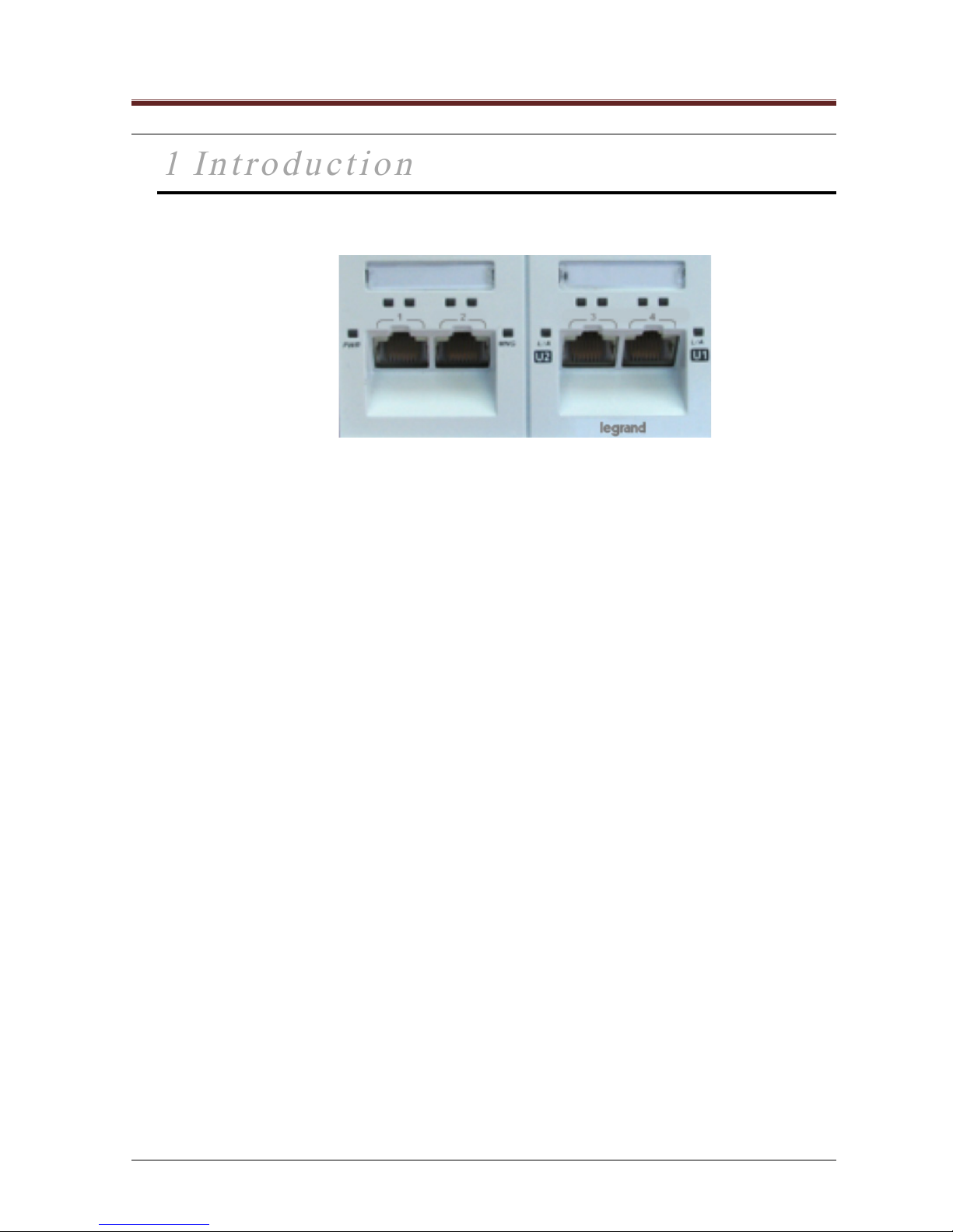
1.1 Overview
Figure 1-1 manageable Mosaic switch
The manageable Mosaic switch is a high end fully manageable six-port installation (duct) switch. It is
specifically designed for Fiber to the Office (FTTO) duct/trunk installations, floor tanks or hollow space
sockets.
The manageable Mosaic switch better suits networks requiring PoE functionality
Main Feature list:
• Four external 10/100/1000M RJ45 A/N auto MDI ports
• 1x Gigabit/100M SFP F/O uplink and 1xRJ45 10/100/1000M daisy chain/uplink ports
• Power over LAN (PoE) option supports IEEE 802.3at/af PDs (PoE+, PoE) on all four
RJ45 external ports
• High power embedded management providing SNMP agent, Web (full Java applet) and
Telnet
• Remote management via Legrand's enhanced Embedded web interface application,
Web browser and Telnet
• Highly secured in-band access via IP access list, secure NMS path, passwords and
optional HTTPS
• Low voltage (52VDC) operation via compact external power supply
• The uplink ports of the manageable Mosaic switch are used for the network/backbone
connections and support star, ring and daisy-chain topologies.
• The manageable Mosaic switch enables distributed network architecture. It provides
efficient use of cable infrastructure and bandwidth using bandwidth aggregation for
remote workgroups. The uplink ports enable connections to other workgroup switches
from which additional devices can be cascaded. Thus, allowing the number of ports in
the network center and cable infrastructure to be reduced for a simple installation and
maintenance process.
• The manageable Mosaic switch is an advanced, full-featured switch with sophisticated
attributes built-in. 802.1x per port access control & HTTPS support on embedded web
interface.
SUMMARY
Page 8

Manageable Mosaic switch Installation and User Guide
Page 8 of 87
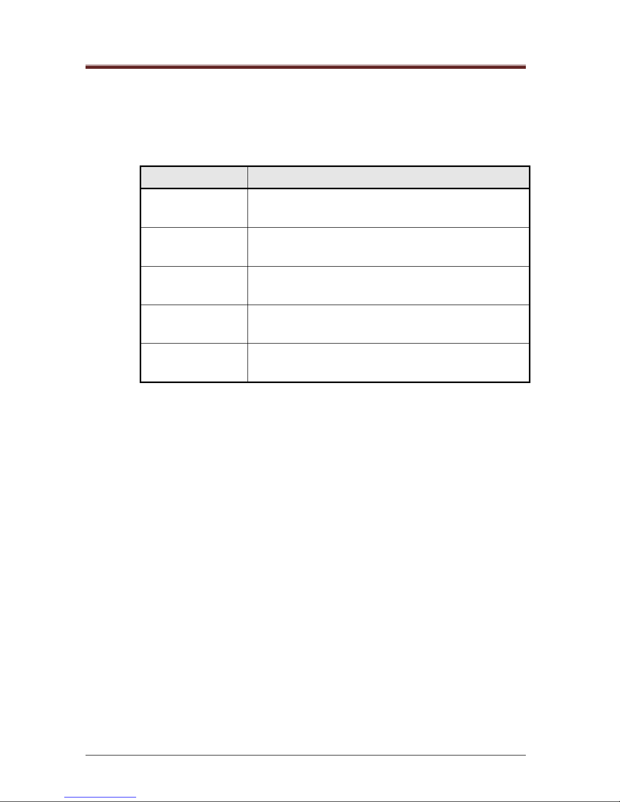
1.2 General Characteristics
Table 1-1 manageable Mosaic switch Characteristics
Ports 1 to 4
(external user
ports)
10/100/1000BaseT.
Auto-negotiate, auto MDI, and polarity
100 meter (330 Feet) distance over TP cables Cat5e and higher
F/O SFP Uplink
Port
Interface – fiber optic SFP transceiver
Provided with 1000 base-SX multimode (MM), 850/1310nm;
connectors: SFP (LC) SC
Accept also single-mode (SM) 1310/1550nm; connectors: SFP (LC) SC
Compatible with 1000 base-SX 1000 base-LX
RJ45
Uplink/daisy-chain
Port
10/100/1000BaseT.
Auto-negotiate, auto MDI, and polarity
100 meter (330 Feet) distance over TP cables Cat5e and higher
QoS and VLANs
QoS / CoS configuration with four traffic classes and prioritized packet
streams per port. QoS based on IEEE802.3ac or IP TOS (supporting
IPv4, IPv6).
802.1Q VLAN, support 64 VLANs, tag insertion and removal.
Double tag support, Transparent VID.
Access Security
(per port)
Port based MAC access security.
802.1Q VLAN, port based VLAN
802.1X Port based network access control.
Management
Management
Security
SNMP management agent with in-band connection supporting SNMP,
Telnet and Web
Manageable via Telnet (IP) and Web.
Three password protected access levels.
Get Community and Set Community passwords.
Management access list ("white" IP address list).
Management access path.
Management by specific VLAN.
Management user authentication through up to four Radius servers for
Web access.
Spanning Tree support
SUMMARY
Page 9

Manageable Mosaic switch Installation and User Guide
Page 9 of 87
Additional
Features
RSTP/STP Spanning Tree support
IGMP Snooping
Monitoring
Event logging, filtering and sorting, prioritization and trap management
(up to 8 trap destinations) with notification.
Port level RMON and statistics.
Port monitoring (mirroring) for data analysis / recording.
Global device
management
Internal voltage and temperature measurement, thresholds and events.
Control of switch learning and aging parameters.
User's name assignment on device and port levels.
Reset, configure and restore factory defaults via SNMP, Telnet and Web.
Software
download
Remote firmware updating capabilities.
Upload/download device configuration.
Special features key activation.
Set-up and testing
Secured remote initial set-up via LCS2 - FTTO Init (Legrand remote
device initialization application).
Power Supply
AC input voltage: 100–240 VAC, 50/60Hz
Manageable Mosaic switch Power Consumption:
- 8 Watts, without PoE
- 60 Watts max with PoE
SUMMARY
Page 10
Manageable Mosaic switch Installation and User Guide
Page 10 of 87
1.3 Manageable Mosaic switch Shipped Components
The manageable Mosaic switch is shipped with the following components:
• Manageable Mosaic switch
• Mosaic power supply.
1.4 Front & Side panel components
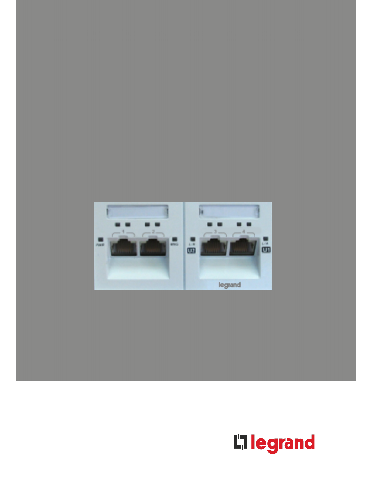
manageable Mosaic switch front panel contains LED indicators for Ports 1–4 as well as for the Uplink Ports
(Power, Management and the PoE LEDs are also located on the front panel.
Figure 1-2 manageable Mosaic switch Front view
(1) To press the Reset button user needs to remove first the user identification marking slide. Use
narrow tool such as needle to press the button. Keeping the button pressed for a long period
(few seconds) will force to unit to switch to the default factory settings.
Power LED
Port 1 L/A &
PoE LEDs
Port 2 L/A &
PoE LEDs
Port 3 L/A &
PoE LEDs
Port 4 L/A &
PoE LEDs
Management
LED
Uplink 2 L/A LED
Uplink 1 L/A LED
CLI Connector (reserved)
Uplink 1 RJ45 Port
Uplink 2 SFP Port
Main DC Power
Connector
User Identification
Marking Slides
Reset
(1)
Internal
Push button
SUMMARY
Page 11

Manageable Mosaic switch Installation and User Guide
Page 11 of 87
Figure 1-3 manageable Mosaic switch Side view
(2) The two RJ45 built-in LEDs, part of Uplink 1 RJ45 connector,
are not active in the manageable Mosaic switch
1.4.1 LED Indications
Table 1-2 lists the LED indicators and their description.
Table 1-2 manageable Mosaic switch LED Descriptions
LED Indicators
Description
Power
ON
– Main Power connected and power supply OK
Network Management
System (NMS)
OFF
ON
– Management startup/inoperable
– Management up and active
Uplink 1-2 L/A (Link
Activity)
OFF
ON
BLINKING
– no link
– link established on uplink port(s)
– activity detected (TX and / or RX) on the port(s)
PoE Ports 1-4
OFF
BLINKING
ON
– PoE / PSE disabled on the port
– PoE / PSE enabled, but PoE power not provided to
the port (PD device not detected on the port)
– PD detected, PoE / PSE power (52VDC) provided to
the port
Ports 1-4
OFF
ON
BLINKING
– no link
– link established
– activity detected (TX and / or RX) on the port(s)
Uplink 1 RJ45 Port
(2)
Uplink 2 SFP Port
Cooling Plate
Shield Terminal
Main DC Power Connector
Front Panel
Uplink 1 RJ 45 ethernet port
SUMMARY
Page 12

Manageable Mosaic switch Installation and User Guide
Page 12 of 87
1.5 Remote Management Options
The manageable Mosaic switch can be managed via any of the following two management
interfaces:
The Embedded web interface Web Management application - from any Web browser - as
an applet
• Telnet connection
Factory defaults configure all three management interfaces to be active. This configuration can
be changed so that the device can only be managed by one or a combination of two
management interfaces.
SUMMARY
Page 13

Manageable Mosaic switch Installation and User Guide
Page 13 of 87
2
2
Hardware
Hardware
Installation
Installation
2.1 Overview
The manageable Mosaic switch features a compact design with a low mounting depth that fits into
standard 45x90 or larger faceplates and ducts. Installation of the manageable Mosaic switch includes
the following recommended steps:
• Mount the manageable Mosaic switch external PS (Power Supply) in the duct and connect the
PS to the main power
• Connect the DC connector of the PS to the manageable Mosaic switch (the manageable
Mosaic switch should start booting)
• Performing initial IP configuration of the specific device:
a. Connecting a PC/laptop via LAN cable to any manageable Mosaic switch port and setting the
IP parameters via the LCS2 - FTTO Init application.
b. Connecting a PC/laptop via the manageable Mosaic switch special RS232 serial cable
(optional) to the CLI connector of the manageable Mosaic switch, performing manageable
Mosaic switch restart and following the options.
• After the IP parameters are set, connect the manageable Mosaic switch to the network (via the
F/O uplink and/or copper uplink/daisy-chain ports)
SUMMARY
Page 14
Manageable Mosaic switch Installation and User Guide
Page 14 of 87
3
3
Device Management
Device Management
3.1 Overview
The manageable Mosaic switch can be managed remotely through the Embedded web interface EMS
(Element Management System) application via any Web browser or via Telnet.
The Embedded web interface EMS application can be installed on any computer running a Windows 98
/ 2000 / XP / Vista / 7 platform, Linux or Solaris. This software requires prior installation of the Java
JRE1.6 minimum.
Remote management can also be conducted from any Web browser which has access to the Legrand
device network. The Web browser launches a complete Embedded web interface GUI using a Java
applet (see Section 3.2).
The device may also be managed via Telnet (see Section 8).
3.1.1 User Names / Access Levels and Passwords
Each Embedded web interface session, is accessed by logging in using one of three user names,
representing access levels, and its respective password. Factory default passwords are available for
each user name.
User Name / Access Level
Default Password
Guest
guest
Admin
admin
Technician
tech
Service Center
Not Available
CLI password
mypass
Table 3-1 User name access level and password
The four user names (access levels) are as follows:
• Guest– Allows only monitoring and viewing the configuration and status
information. Password, configuration and traps option are not accessible at this
level. Default password is guest.
• Admin– Allows access to all configuration options except for service options such
as power supply thresholds and Technician’s password (accessible by Technician
level). Default password is admin.
• Technician – Allows access to all configuration options and to service options such
as temperature and power supply thresholds. Also, login as a Technician to gain
access to the System Configuration window Firmware Update tab. A Technician
can change the password for all other user levels, and change default factory
settings. The default password is tech.
• Service Center – Not available in this version.
SUMMARY
Page 15

Manageable Mosaic switch Installation and User Guide
Page 15 of 87
3.1.2 Management Passwords Scheme
Legrand devices can be managed in several ways: with the Embedded web interface application,
through Web access or via Telnet. Each way has its own password scheme as follows:
• When using the Embedded web interface application all user access level
passwords are stored in the application and can be changed through it. Embedded
web interface allows access to all Legrand manageable devices.
• The passwords for Web access to manage Legrand devices are stored in each
individual device. They can also be stored in up to four Radius servers, allowing
central password management. Passwords stored in the device can be changed
via the Telnet command set http password (see Section 8) while passwords
stored on the Radius servers are changed in the Radius server itself. Upon logging
in to the device, the password is verified either according to what is stored in the
individual device or, if configured to the Radius server, is authenticated by one of
the Radius servers (see Section 3.2.1).
NOTE: In the case where multiple Radius servers are present, authentication begins at the
first Radius server in the Radius Server Index List. If that Radius server is not found,
authentication automatically proceeds to the next Radius Server in the list.
If a Radius Server is found, but does not authenticate the user, the authentication process
is ended and no further search takes place.
• The Telnet connection and the CLI access use the same password (mypass is the
factory default). This password can only be changed via the CLI connection, see
section 8.3. For security reasons, Telnet sessions are automatically terminated
after about 60 seconds of idle time and require reconnecting and login (see Section
8).
3.2 Launching the Embedded web interface Application via
a Web Browser
1. Verify that your computer is connected to the same network as that of the manageable
Mosaic switch unit to be managed.
NOTE: The Embedded web interface Web application is a Java-based application. In order
to use the Embedded web interface Web application, JRE (Java Runtime Environment) or
JVM (Java Virtual Machine) must already be installed on your computer. Java is freeware
and can be downloaded from: www.javasoft.com.
2. This software requires prior installation of the Java JRE 1.6 minimum.
Launch your Web browser. In the browser address bar type the IP address of the
manageable Mosaic switch unit to be accessed and press enter. It may take a few
seconds for the Java applet to load the Embedded web interface application GUI.
Once completed, the Login window appears as shown in Figure 3-1.
SUMMARY
Page 16

Manageable Mosaic switch Installation and User Guide
Page 16 of 87
Figure 3-1 Login Window via the Web Browser
3. Choose your user name according to the three user access levels available. (Guest,
Admin, or Technician). (User access levels are described in Section 3.1.1).
4. Enter the appropriate default password guest, admin or tech.
NOTE: User level passwords cannot be changed via the Web browser; they can only be
changed via Telnet (see Section 0) or controlled by a Radius server. (Section 3.2.1).
5. Be sure that the Get and Set Community strings match the Community parameters of
the target device, or change them accordingly. SNMP Get community – public
SNMP Set community – private (Community parameters are discussed in
Section 5.1.1).
6. Click Connect in order to see the Embedded web interface main screen. You can now
manage the device (see Section 3.3).
3.2.1 Using Radius Server Password Authentication
Legrand manageable devices can be configured to seek user level password authentication from a
central Radius server, such as from a Freeradius, Winradius or Radiator server, while logging in from a
Web browser. The advantage of storing user level passwords in the Radius server is that if the Web
management passwords are changed, they need to be changed only in the Radius server and not in
each individual device.
Telnet is used to direct a Legrand manageable device to seek password authentication from the Radius
server while logging in from a Web browser. (See Section 0)
3.3 Port Level Configuration
Port configuration is done via port view windows. To access the port view windows, in the Embedded
web interface main screen, click the port icon and the port’s view related window appears.
NOTE: The name of the port view window matches the type of port. For example, clicking
the Uplink port icon, will bring up the configuration window name is Uplink View; click Port
1, and the configuration window name is port 1 View, etc. The appearance of the
configuration windows, and the available configurable port parameter options differ for
copper and for F/O ports. When an option is not available for the selected port type, the tab
is not displayed.
SUMMARY
Page 17

Manageable Mosaic switch Installation and User Guide
Page 17 of 87
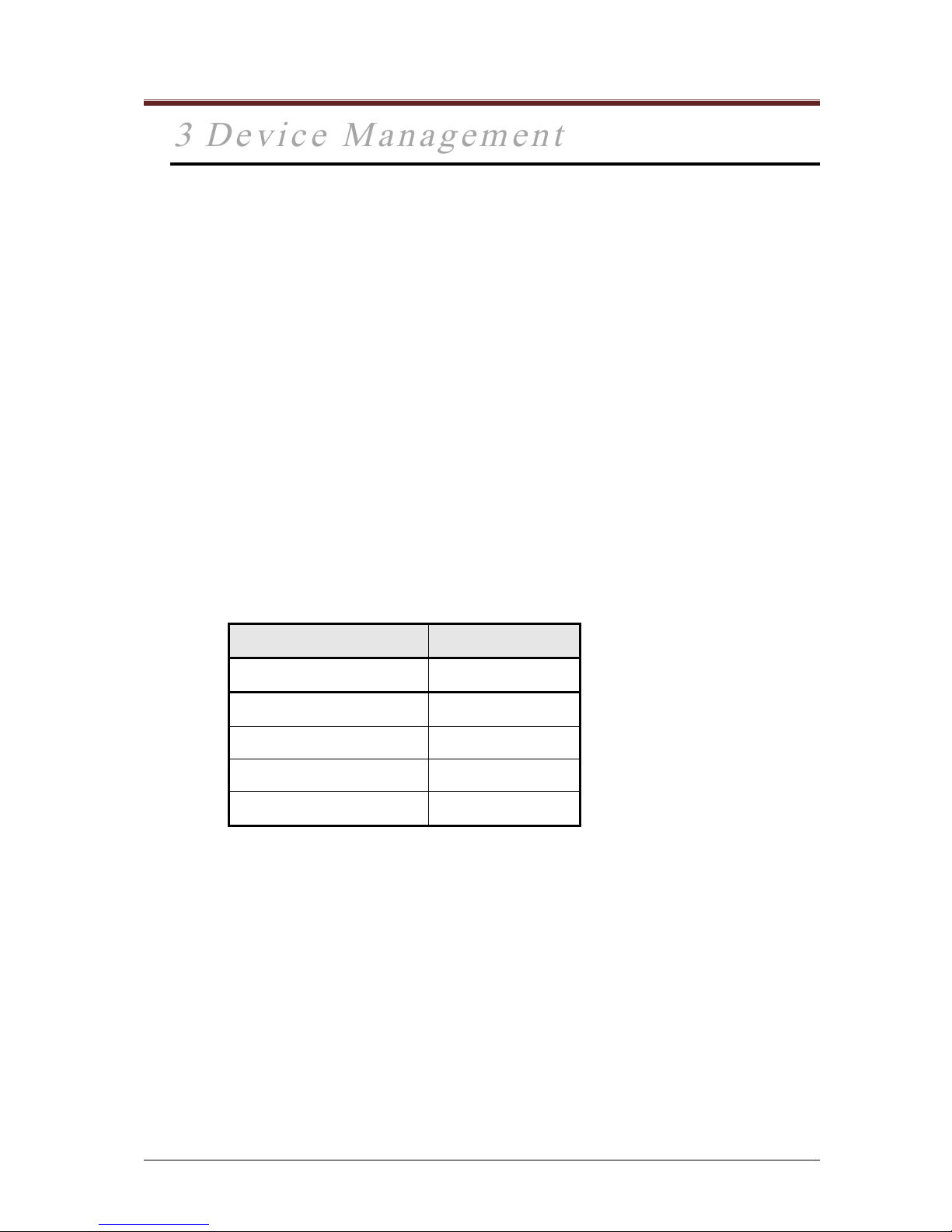
3.3.1 Port Details and Status
The Port View screen shows information about the port, connection type and status.
To view this information, click the Properties and Status tabs.
Figure 3-2 Port configuration, Properties and Status tabs
The Port View configuration window includes the following tabs, depending on port type.
Table 3-2 Port Configuration Options
Parameter
Description
Properties:
Displays port description and connection type.
Assigns a name to a specific port.
Status:
Provides visual indications of port status and activity.
The indicators include Link, Activity and Collision.
Administration:
Contains the port status, speed, duplex, negotiation
and flow control settings. Part of the parameters use
scroll bars, for the user to select between available
options
Monitor:
Allows port monitoring to be enabled or disabled.
PoE
Allows control of port’s output power. (Not available
for uplink ports
SUMMARY
Page 18

Manageable Mosaic switch Installation and User Guide
Page 18 of 87
Table 3-2 Port Configuration Options
Parameter
Description
MAC Security:
(Copper ports only)
Allows individual ports to be disabled.
QoS:
(Copper ports only)
Allows setting the Quality of Service parameters of
the port.
Statistics:
Displays various statistics regarding traffic, port
usage, and packets.
SFP: (SFP ports only)
Contains specific information concerning the type of
SFP connector in the port, including type, bit rate,
wavelength, vendor, model type and serial number
NOTE: On SFP ports, the connector type and other physical descriptions of the port are
found in the SFP tab only, and not in the Properties tab
3.3.2 Configuring the Port Name
Each port can be named in order to identify the user or device connected to that port. In the specific
Port View window, click the Name field to enter the new value and then click Apply.
3.3.3 Factory Default Port Settings
The device ports are factory preset with the following default values:
Table 3-3 Factory Default Port Configuration Values
Parameter
Description
10/100/1000BaseT copper ports:
Status – On
Auto Negotiate – Enabled
Speed – Depends on A/N results
Duplex – Depends on A/N results
MDI – Auto
Flow Control – Enabled
PoE – Disabled on external user ports
SUMMARY
Page 19
Manageable Mosaic switch Installation and User Guide
Page 19 of 87
Table 3-3 Factory Default Port Configuration Values
Parameter
Description
F/O SFP Uplink port:
Port Status – On
Auto Negotiate – Enabled
Speed – Depends on A/N results
Duplex – Depends on A/N results
Flow Control – Enabled
3.3.4 Changing Port Settings
Figure 3-3 Administration tab, Copper Port Configuration
To change the port settings
1. From Port View, expand the Administration tab.
2. Change the appropriate parameters with new values and click Apply.
The left side of the field consists of the parameter set by the user (Admin). The parameters on
the left side reflect the configuration identified by the operant (Oper)
SUMMARY
Page 20

Manageable Mosaic switch Installation and User Guide
Page 20 of 87
Table 3-4 Administration tab, Copper Port Parameters
Copper Port Parameters
Description
Status
Disables / Enables the port; Options: On, Off
Mode
Port speed and duplex setting.
--Auto-negotiate – the port is set to negotiate speed and
duplex mode with the link partner.
--Manual – speed and duplex are manually defined. Usually
used when connecting to devices which do not support
auto-negotiation or when link parameters must be forced.
Auto Neg. Type
Select the type of Auto Negotiation Preferred/Forced
Master/Slave
Speed
Applicable if auto-negotiation is set to Manual.
Options: 10M, 100M, 1000M.
Duplex
Applicable if auto-negotiation is set to Manual.
Options: Full duplex, Half duplex.
MDI/MDIX
--Auto Negotiate – Three advertise possibilities:
1) MDI and MDIX, 2) MDI, 3) MDIX
--Manual – Two possibilities: MDI or MDIX
Flow control
Enables / Disables flow control.
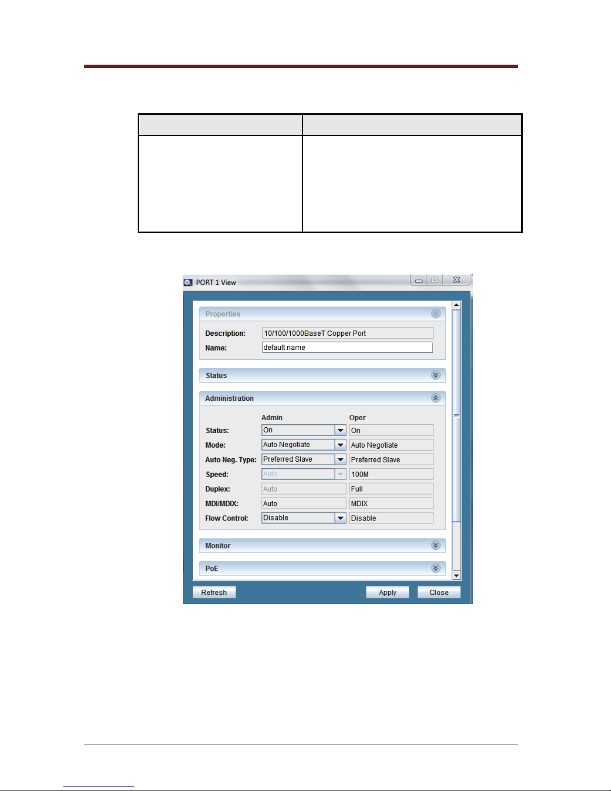
In case of SFP F/O port, the properties port description will be SFP 1000BaseX Fiber Port or SFP
100BaseFX Fiber Port. The following figure list the Administration and SFP tabs, for the SFP port
configuration
SUMMARY
Page 21
Manageable Mosaic switch Installation and User Guide
Page 21 of 87
Figure 3-4 Administration & SFP tabs, SFP Port Configuration
Table 3-5 Administration & SFP tabs, SFP Port Parameters
Administration & SFP
Port Parameters
Description
Status
Disables / Enables the port; Options: On, Off
Speed
Displays 1000M or 100M, in accordance with the SFP
plugged in transceiver. Otherwise, it is kept in Auto. Oper
field displays the actual speed value, once it is established
with the F/O link partner.
Duplex
When the system detects 100Mbit SFP it enables Full/Half
Duplex setting for the port. Otherwise, it is kept in Auto
Oper field displays the actual value, once it is established
with the F/O link partner.
Note; The following SFP Port Parameters are read from the plugged in SFP Transceiver
Connector
Identified type of connector
Bit Rate
Identified bit rate
Wavelength
Identified wavelength
Vendor Name
Model Type
Identified Vendor Name, Model Type and Serial Number
SUMMARY
Page 22
Manageable Mosaic switch Installation and User Guide
Page 22 of 87
Administration & SFP
Port Parameters
Description
Serial Number
Temperature
Monitored Transceiver internal temperature. (data available
only if the SFP transceiver supports DDM (Digital Diagnostic
Monitoring)
Tx Power
Monitored Transceiver Transmitted Power. (Data available
only if the SFP transceiver supports DDM (Digital Diagnostic
Monitoring)
Rx Power
Monitored Transceiver Received Power. (Data available only
if the SFP transceiver supports DDM (Digital Diagnostic
Monitoring)
3.3.5 Power over Ethernet (PoE)
On the main GUI main screen a PoE LED image appears above each PoE capable copper port. In
addition, in the Port View window a PoE tab appears.
The manageable Mosaic switch provides 802.3at/af (PoE+, PoE) Power Source Equipment (PSE)
capabilities with a total power capacity of up to 50 Watts on the ports. When an 802.3at/af PD device is
connected to the port, the port detects and classifies the device according to the 802.3at/af standard
and activates the PSE accordingly. If the PD device is not 802.3at/af complaint, it will not be recognized
and the port will not supply PoE power to the PD. The monitoring and management of the PoE
operation of the ports is done from the PoE tab in the Port View window.
3.3.5.1 PoE Management and Operation Tab
If a port is PoE Capable, the PoE tab of the Port View window appears (this tab is not
there in a non-PoE port). From this tab one can turn the PoE option on and off,
configure the disconnect mode, monitor general PoE characteristics and power
consumption, and reset the PoE.
Figure 3-5 Port View Window, PoE tab
SUMMARY
Page 23
Manageable Mosaic switch Installation and User Guide
Page 23 of 87
Table 3-6 PoE Parameters
Parameter
Description
Status
The left selection tab indicates that the port is open for PoE
connections (will supply power if a PD is connected). The
right field indicates whether or not power is being supplied to
the port. An ON indication appears when a PD is detected
and the PSE power is provided to that port. An OFF
indication is when PSE power is not provided to the port due
to several possible reasons: 1) if the Admin Status is OFF
(PoE is disabled on the port) 2) nothing is connected to the
port, 3) the device connected to the port is not an 802.3at/af
PD device.
Reset
Pressing this button disconnects the PSE Power for about 5
seconds and then automatically re-connects it providing
remote power reset to the PD device.
Disconnect
Select between AC Disconnect or DC Disconnect mode in
the port configuration window. Selecting DC Disconnect
enables detection only of DC PDs (the most common type of
PDs currently). Select AC Disconnect enables detection only
of AC type PDs (mostly old PDs). The default is DC
Disconnect.
Type/PD Class
Indicates the 802.3at/af power classifications of the device
connected to the manageable Mosaic switch port. The type is
indicated by dot3af or dot3at (meaning 802.3at/af) and
ClassX (to indicate which class is connected). In the above
example, no device is connected to the manageable Mosaic
switch, consequently the PD Device Type indicates Class-0
(Load Not Detected) which is the default indication. (See
following table.)
PoE
Class
802.3af
Min Power
Levels at
PSE
output
PoE+
Class
802.3at
Min Power
Levels at
PSE output
0
15.4 Watts
0 30.0 Watts
1
4.0 Watts
1 4.0 Watts
2
7.0 Watts
2 7.0 Watts
3
15.4 Watts
3 15.4 Watts
SUMMARY
Page 24
Manageable Mosaic switch Installation and User Guide
Page 24 of 87
Table 3-6 PoE Parameters
Parameter
Description
4
As Class 0
4 30.0 Watts
Consumption
Displays the actual power being consumed by the PD device
connected to the port.
Voltage
Displays the voltage supplied by the PoE Power Supply to
the manageable Mosaic switch.
3.3.5.2 PoE Power Capacities
The total power capacity of all four PoE ports combined cannot exceed 50 Watts.
Consequently, when connecting PD devices to the ports, the device detects its class
and provides PSE power to the port only if the device can allocate enough power to
that port within the total 50 Watt limitation.
3.3.5.3 manageable Mosaic switch PoE LED Indicators
The existence of the LED itself indicates that the port is PoE Capable. Ports with no
PoE capabilities have no PoE LEDs.
On a PoE capable switch there are three possible PoE LED indications: OFF,
BLINKING and ON (steady illumination).
A: PoE LED OFF: Indicates that PoE is administratively disabled on this port. This can
be changed through the PoE tab in the Port View window.
B: PoE LED BLINKING: Indicates that PoE is enabled on the port, but no PD is
connected.
C: PoE LED ON (steady illumination): A PD device is detected on the port(s) and PSE
power is provided to those port(s).
3.3.6 MAC Security
There are two modes of MAC security:
• MAC Access Security is locally authenticated according to the approved MAC
• The Approved MAC is authenticated by the Radius server before continuing with the
MAC Access Security process.
The MAC security mode is selected only through the Telnet application. See Section 8.5.
SUMMARY
Page 25
Manageable Mosaic switch Installation and User Guide
Page 25 of 87
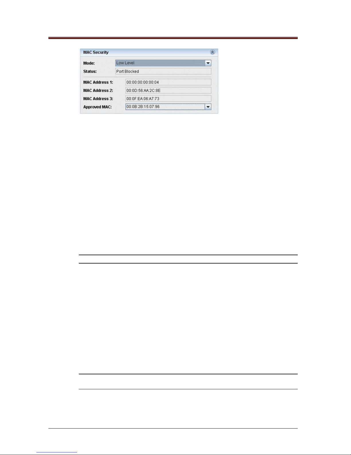
Figure 3-6 Port View menu, MAC Security tab
MAC Security Configuration Fields:
• MAC Address 1-3 list displays the MAC address entries belonging to that port in the
look-up table.
• Approved MAC field displays the specific MAC address to be secured (the MAC
address according to which the MAC security algorithm works).
• Mode field displays the MAC security operation mode (disabled, low security or high
security).
• Status field displays the port security status (disable, port forwarding, or port blocked).
When disabled appears in the Status field, this means that the MAC security is
disabled. When port forwarding or port blocked appears in the Status field, this
means that the MAC security is enabled and that specific port is either forwarding or
blocked in accordance to the MAC security algorithms.
NOTE: Port Monitoring, MAC security and 802.1X cannot be active at the same time.
1. In the Approved MAC list select the MAC address to be designated as the
approved MAC address.
2. Open the Mode list and set the mode according to the following parameter
descriptions:
• Disable – MAC security is not enabled.
• Low Security Level – The port is open (forwards data) for all devices as long as
the approved MAC address exists on the port's look-up table. When the designated
device is disconnected and its MAC address is removed from the port table, the
port blocks data communication to all devices.
• High Security Level – Only the designated approved MAC address can use the
port (i.e., only the approved MAC address exists on the port’s look-up table). If the
port receives frames from another device (other addresses in the look-up table),
then the port blocks all data transmission, even for the approved address.
NOTE: When a port is blocked through MAC Security it is detected as a major event and
an appropriate trap is sent to the authorized SNMP managers.
SUMMARY
Page 26
Manageable Mosaic switch Installation and User Guide
Page 26 of 87
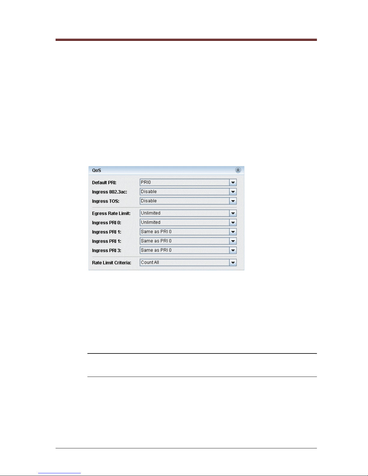
3.3.7 QoS
The packet flow through each port is defined by the Ingress / Egress Policy. manageable Mosaic switch
provides three criteria that determine the policy:
• QoS priority information
• Rate Limit
• 802.1Q based VLANs
3.3.7.1 QoS Priority Definitions
The manageable Mosaic switch uses an advanced non-blocking, four priority output port queue
architecture. Frames exit the switch using a weighted, fair queuing scheme in which 8, 4, 2, 1 is applied
to the four priority output queues: eight frames from priority 3 egress, followed by four frames from
priority 2, etc. Ingress frames are queued to the proper output queues according to their priority. The
frame priority is determined either in the 802.3ac tag or in the TOS field.
Figure 3-7 Port View menu, QoS tab
QoS priority definition criteria
• Default PRI (priority level) – Sets the priority level of ingressing frames arriving
without a priority level (four priority levels: 0-3).
• Ingress 802.3ac – Enables queuing of ingressing frames with 802.3ac tags
containing 802.1p priority information to be queued accordingly.
• Ingress TOS (Type of Service) - Enables queuing of ingressing frames with IPv4
TOS / DiffServ or IPv6 Traffic Class priority to be queued accordingly.
NOTE: If both Ingress IEEE 802.3ac and Ingress ToS are enabled, and a frame arrives
with both types of priorities set, the frame will be queued according to the IEEE 802.3ac
information.
3.3.7.2 Rate Limit Definitions
Frames enter (ingress) the port at the rate limit allocated to their identified priority level. Frames without
a priority level, enter the switch at the rate limit assigned to the port (default PRI parameter). All frames
exit (egress) the port at the Egress rate limit.
The manageable Mosaic switch support progressive Ingress rate limits for four priorities, where the rate
for each priority level is relative to the previous level. Only Priority-0 is assigned a value.
For example, if Priority 0 rate is set to 8 Mbps, then priority 1 rate may be the same or double that of
priority 0, priority 2 rate is the same or double that of priority 1, etc.
SUMMARY
Page 27
Manageable Mosaic switch Installation and User Guide
Page 27 of 87
To define QoS Rate Limits:
1. Click on the Ingress PRI0 field to set its value, or on Ingress PRI1 through Ingress
PRI3 to set their value according to PRI0.
Table 3-7 Rate Limit Parameters
Parameter
Available options
Egress rate:
Not limited or Limited to one of the defined rates between 128
Kbps to 8 Mbps (128K; 256K; 512K; 1M; 2M; 4M; 8M)
Ingress PRI 0:
Unlimited or in seven steps to a value between 128 Kbps to 8
Mbps (128K; 256K; 512K; 1M; 2M; 4M; 8Mbps).
Ingress PRI 1:
Same as PRI 0 or double (i.e. unlimited up to 16 Mbps
depending on PRI 0 settings).
Ingress PRI 2:
Same as PRI 1 or double (i.e. unlimited up to 32 Mbps
depending on PRI 0 & 1 settings).
Ingress PRI 3:
Same as PRI 2 or double (i.e. unlimited up to 64 Mbps
depending on PRI 0, 1 & 2 settings)
The manageable Mosaic switch also supports different Rate Limit Criteria when counting
packets. The switch can count all packets, broadcasts, multicasts and FUcasts in some
combinations.
To define the Rate Limit Criteria:
1. Click the Rate Limit Criteria field and select the appropriate value from the list.
SUMMARY
Page 28

Manageable Mosaic switch Installation and User Guide
Page 28 of 87
3.4 Embedded web interface Menu system
The Embedded web interface main screen provides all devices and port configuration screens plus a
summary of events and fault analysis options. The screen provides a graphic view of the manageable
Mosaic switch device including color indications on ports and LEDs to indicate status, as in Figure 3-8.
Manageable Mosaic switch module may be placed horizontal or rotated vertically, yet the screen
graphic will always appear as in Figure 3-8.
Figure 3-8 manageable Mosaic switch Main Screen
The top left side of the screen consists the device’s identifying information such as its IP address and
user's defined name, location and contact person. These names are only used to identify the device to
an administrator or technician. See Section 5.2 for information on how to change these fields.
Next, on the left side of the screen are the Device configuration icons: System, Features, Files, Users,
Management and Relogin which provide the following options:
Menu Option
Description
Provides access to the following tabs and fields :
❧ Properties – Description, Uptime, Name, Location,
Contact
❧ Inventory – FW Version, HW Revision, Loader Version,
MAC Address, Serial Number, PoE Module, Max. PoE
Pwr, Manuf. Date
❧ Power Supply – Type, Model, Nominal Power
❧ Environment – Temperature, Internal Voltage, access to
Thresholds settings
❧ Factory Defaults – User's Port Status (select On or
Off), Backbone VLAN (select Enable or Disable), access
to the Restore command
❧ RADIUS Server – Radius Server IP Addresses, Shared
Secrets, Auth. HTTP Users
❧ Commands – Provides access to the Reset Device
command
SUMMARY
Page 29

Manageable Mosaic switch Installation and User Guide
Page 29 of 87
Menu Option
Description
Provides access to the following tabs and fields:
❧ Global Configuration – Aging (16 Sec; 300 Sec; 1800
Sec; or No Aging), Learning (select Enable or Disable),
PONL (not available), Priority Policy (select Scheduled
8421 or Scheduled 1111).
❧ VLAN Mode – Select VLAN Disabled, 802.1q VLAN
Enabled, Port Based VLAN Enabled
❧ 802.1q VLAN Membership – Shows a list of VLAN
members, and provides a dialog to either Add or Delete
entries
❧ 802.1q Port Settings – Provides a table view for port
settings
❧ Port Based VLAN – Provides a table view of Port
based VLAN settings with option to select or clear all
❧ Transparent VID - Provides a table view of Port based
VLAN settings
❧ RSTP Settings – Priority, Designted Root, Root Cost,
Root Port, Bridge Max. Age, Bridge Hello Time, Bridge
Fwd. Delay
❧ RSTP Ports Configuration - Provides a table view of
the RSTP Ports Configuration
❧ IGMP Snooping Configuration – Status (Enable,
Disable), Join and leave Messages
❧ IGMP Snooping Discovered Configuration -
Provides a table view of the IGMP Snooping
discovered Ports Configuration
❧ Provides access to the following tabs and fields :Files –
List the Type, Name and Size of the file
❧ Operation – File name, Status, Progress and Command
bar to allow manual downloads of files from remote
servers, or uploading of a local config file
❧ File Server – FTP IP Address, User Name and
Password
Allows changing user passwords for Embedded web
interface (Only accessible through the Stand-Alone
program).
Includes the following management tools:
❧ Traps – IP Addresses of Trap Destinations
❧ Access List – IP Address access list
❧ Management Interfaces (Telnet/Web/SNMP)
❧ Secure NMS Path options
❧ License details (Features and Key)
❧ About – Embedded web interface Version iformation
Allows signing in as a different user and/or to a different
device, without completely restarting the program
(Accessible only through the Stand-Alone program).
Table 3-8 Device configuration options
SUMMARY
Page 30

Manageable Mosaic switch Installation and User Guide
Page 30 of 87
The device level configuration options are accessed by clicking the appropriate icon on the left side of
the screen. The port level configuration menus are accessed by clicking on the specific port in the
graphic view.
3.4.1 Port Indications
The manageable Mosaic switch main screen displays color-coded port management characteristics
through icons and LEDs that indicate the status of each port).
Note; Management of the device relates to port numbers, and not necessarily to the default visual
display.
Table 3-9 Color and icon Indications
Copper Port connector
Icons and Colors:
Grey – No connection / link
Green – Link without activity
Yellow – Link with activity (Normal operation)
Red – Collisions
Red X on the port icon (top left corner) – Port
administratively closed.
HTTPS icon (HTTPS enabled)
Fiber Port connector icons:
Four colors: grey, green, yellow and red to indicate port
status, same as for the copper port.. The F/O port uses
different icons to reflect connector type:
Duplex SC
Duplex ST
SFP Empty
SFP
MAC access and 802.1X
security icons on copper
ports:
A lock icon within a port icon indicates that either MAC or
802.1X Network Access Security is enabled.
Grey with Green lock – Security enabled on
SUMMARY
Page 31

Manageable Mosaic switch Installation and User Guide
Page 31 of 87
the port, port access is open
Green with Red lock – Port connected and
blocked by the activated security
NOTE: Red lock icon is used in case of two blocking events. First when 802.1x port is
enabled by manageable Mosaic switch but not yet authorized. Second is when MAC
security mode is enabled but the MAC address is not authorized. In the two case events,
once the port is authorized, the lock icon change from red color to green
The manageable Mosaic switch main screen provides also LED indication on manageable Mosaic
switch unit and port status. Table 3-10 lists the LED indication through the GUI:
Table 3-10 LED Indications
LED
ON
OFF
L/A (Link/Active)
Ports 1-4, Uplink
Ports U1, U2
Port connected (link established).
Port not connected.
PoE
Ports 1-4
PoE power provided to the port
(PoE enabled, and PD device
connected to the port).
LED blinking specifies PoE
enabled but no PD device
PoE power is NOT provided to
the port.(PoE disabled)
NMG
Managed device, management
agent active.
Unmanaged device or
management agent inactive.
Power
Power is being supplied to the
unit.
Power is not being supplied to
the unit.
SUMMARY
Page 32

Manageable Mosaic switch Installation and User Guide
Page 32 of 87
3.5 Device Configuration Menus
The icons on the left provide device level information and configuration options. Clicking the appropriate
icons will open the requested information/configuration window, to enable configuration of the
manageable Mosaic switch unit.
Each configuration page includes several tabs. Double click on tab will enable access to all
configuration parameters. Fields within the specific page contain bars with either information data (no
editing option), command line to type a required value or scroll bar to select between available options.
The following three bars are used in all menu pages:
• Close – Close page menu. Closing the page without save of the changes will pop up a menu for
the user to assure if the changes should be lost. Click Yes to ignore changes and leave page.
Click No to return back to page.
Figure 3-9 Close pop-up menu
• Apply – Save new setting parameters. In case changes in setting parameters, a popup menu
will verify if the user wants to save the changes. Click No to ignore changes or Yes to save
changes.
Figure 3-10 Apply pop-up menu
• Refresh – Used to refresh displayed page with the latest saved parameters. In case of any
change in setting parameters, a pop-up menu will verify if the user wants to keep or ignore
changes. Clock Yes to ignore changes or No to keep displayed changes
Figure 3-11 Refresh pop-up menu
SUMMARY
Page 33

Manageable Mosaic switch Installation and User Guide
Page 33 of 87
3.5.1 System Device Information
Figure 3-12 System View menu, Properties tab
The Properties tab of displays the device Description, Up Time and allows Name, Location and
Contact information to be assigned to the device. Assigning these device details helps the system
manager locate and identify devices in the network. It is recommended to assign such details to each
unit.
To define device information:
1. Click on the System icon and select the from the System View menu the Properties tab
Click on the Name field.
2. Edit the Name, Location and Contact fields.
3. Click Apply.
4. Text updated is displayed in Blue to indicate data is not send yet to the device. Once
the user clicks Apply, data is send to the device and field color data is changes to
black.
SUMMARY
Page 34

Manageable Mosaic switch Installation and User Guide
Page 34 of 87
3.5.2 Inventory
Figure 3-13 System View menu, Inventory tab
The Inventory tab displays information about the device hardware. Max PoE power specifies the
maximum power that may be sourced through the port’s PoE
3.5.3 Power Supply
Figure 3-14 System View menu, Power Supply tab
The Power Supply tab displays information about the power supply type, model and the nominal power
of the unit.
3.5.4 Environment
Figure 3-15 System View menu, Environment tab
The Environment tab displays the current operating temperature of the device, as measured on-board
voltage of the device. The temperature and voltage limits, set for the unit, define the alert thresholds.
The limits can be modified by a Technician level user at any time.
The temperature thresholds should only be changed if the installation/operation environment requires
that. The factory setup relates to operation in a 25°C environment.
• The default temperature threshold is 55° C.
• The default voltage threshold ranges between 3.15 V (low) and 3.45 V (high).
SUMMARY
Page 35

Manageable Mosaic switch Installation and User Guide
Page 35 of 87
NOTE: It is not recommended to change the default voltage thresholds. Threshold alerts
are only generated when the limits are crossed.
To change the Temperature or Voltage limits:
1. Enter the Management application at a Technician level.
2. Click on the System icon and select the from the System View menu the Environment
tab.
3. Click Thresholds bar at the Environment tab.
Figure 3-16 Thresholds window
4. In the Thresholds window, enter the new Temperature and/or Voltage thresholds and
click OK. Allowed values are:
• Temperature: 0°C - 90°C
• Low voltage minimal value: 3100
• High voltage maximal value: 3500
3.5.5 Factory Defaults
Figure 3-17 System View menu, Factory Defaults tab
The unit default parameters can be restored at any time.
NOTE: This can also be done through Telnet (see Section 8) and LCS2 - FTTO Init.
Restoring the factory default settings will not affect the IP configurations or the Get / Set
Community settings.
To reload the unit default parameters (from a Technician or Administrator level only):
1. Click on the System icon and select the Factory Defaults tab
2. Select desired values for User port status (On/Off), backbone VLAN (Enable/Disable)
and backbone VID. Click the Restore button. Verification prompt appears.
3. Click Yes to confirm.
4. Restart the device, either through the Remote reset option or through the LCS2 - FTTO
Init software. The new settings are applied after Reset.
SUMMARY
Page 36

Manageable Mosaic switch Installation and User Guide
Page 36 of 87
3.5.6 RADIUS Server
Figure 3-18 System View menu, RADIUS Server tab
The RADIUS Server tab displays the current RADIUS server details. RADIUS server details can be
edited from a Telnet connection. RADIUS authentication supported EAP-MD5 only.
3.5.7 Remote Software Reset
The unit may be remotely reset at any time. Reset is required, for example, after a new software version
is uploaded. (The unit may also be locally reset by disconnecting and reconnecting the power or
pressing the front panel Reset push button, located at the left corner of the right user identification
marking slide. For more details see Figure_12).
NOTE: Reset can also be done through Telnet (Section 8).
Figure 3-19 System menu, Commands tab
To reset the unit (from a Technician or Administrator level only):
1. From the Commands tab, click Reset Device. A confirmation window appears. Click
Yes to confirm.
3.6 Features Menus
3.6.1 Global Configuration
• Learning - Switch Learning is always enabled and cannot be configured in this device.
• Aging time –. Aging time can be set to 16 seconds, 300 seconds (5 minutes), 1800 seconds
(30 minutes) or No Aging. The Factory default aging settings is 300 sec.
NOTE: No Aging means the MAC addresses in the look-up table will not be removed
automatically
• Priority Policy – Set the desired priority to select between two options 8421 and 1111. In case
of 1111 there is equal priority in the queuing and forwarding frames. In case of 8421, a
weighted fair queuing scheme is applied to the four priority output queues: eight frames from
SUMMARY
Page 37

Manageable Mosaic switch Installation and User Guide
Page 37 of 87
priority 3 egress, followed by four frames from priority 2, followed by two frames from priority 1
and last one frame from priority 1. If level of forwarding is similar between the ports, it is
recommended to use priority option 1111. Otherwise, use 8421.
• PONL –Not relevant to this product.
It is for the user to set the right configuration of Aging time and Priority policy in order to enable the most
efficient network performances, according to the application that runs on the network and the type of
devices connected to the specific ports.
The switch maintains an updated MAC address look-up table by continuously learning and flooding. The
switch can be configured to remove unused addresses or those that are not used for a specified period
(via aging time) so that time is not wasted forwarding to an irrelevant port.
Each new look-up table entry is given a timestamp. Every time a packet is received from a node, the
timestamp is updated. The entry is erased from the look-up table; after the user configurable length of
aging time with no activity from that node (MAC address) has elapsed.
Setting a too short value for aging time may cause addresses to be removed prematurely from the
table. In this case, when the switch receives a packet for that destination, it floods the packet to all
ports. This unnecessary flooding can impact network performance. Setting too long an aging time can
cause the address table to be filled with unused addresses; it can cause delays in establishing
connectivity when a workstation is moved to a new port.
Address migration capabilities – when a device is moved to a differed port in the same switch, the move
is identified by the switch, after the first transmission from the device, and the MAC table immediately
updates without aging as soon as the connected device transmits signals.
Figure 3-20 Features menu, Global Configuration tab
3.6.2 VLAN Mode
The IS-2 supports 802.1Q VLANs and Port Based VLAN. Before a VLAN can be defined, the VLAN
type must be selected from the VLAN Mode tab.
Figure 3-21 Features menu, VLAN Mode tab
NOTE: Only one type of VLAN setting can be active at any given time. If 802.1q VLANs
are enabled, the Port Based VLAN (port forwarding table) is Disabled, and vice-versa.
Port-based VLAN is similar to private VLANs in Cisco terminology, where are 802.1q VLAN is close to
switchport access/trunk modes in Cisco terminology.
SUMMARY
Page 38

Manageable Mosaic switch Installation and User Guide
Page 38 of 87
3.6.3 802.1Q VLAN Membership Configuration
The 802.1Q VLAN Membership tab defines the VLAN IDs (VIDs) and the port membership for each of
the VLANs. For practical reasons, only up to 64 VLANs may be defined in the IS-2, with VIDs ranging
from 1 to 4095.
Before a VLAN can be used on the switch, its ID must first be defined in the VID list below, then all ports
that will participate in this VLAN will be checked against this VID. For an access port, only one VID
should be associated with a given port, for a trunk port, all VLANs carried over the trunk should be
associated with the trunk port.
Figure 3-22 Features menu, 802.1q VLAN Membership tab
To configure VLAN membership
1. Click on the Features icon and select from the Features menu the VLAN Mode
tab, Select 802.1q VLAN Enabled.
2. From the 802.1Q VLAN Membership tab, click Add. A prompt appears,
requesting a New VLAN ID number. Enter a number that is not currently used
by an existing VLAN, then click OK.
3. Now that the new VLAN appears on the 802.1Q VLAN Membership tab, check
all the ports to be included in the VLAN and click Apply.
To delete a VLAN:
• Select that VLAN from the list in the 802.1Q VLAN Membership tab and click
Delete. The VLAN is deleted without verification.
To edit a VLAN:
• Click on the ports to edit, set the required changes and click Apply.
SUMMARY
Page 39

Manageable Mosaic switch Installation and User Guide
Page 39 of 87
3.6.4 802.1Q Port Settings
The 802.1Q Port Settings tab should reflect the condition (tagged/untagged) of the traffic expected on
the associated port.
For an access port, the default VID for the port should match with the only VID associated with the port
in the previous tab (802.1Q VLAN Membership). Egress Tag remove should also be checked, and
Egress Tag Insert should be left unchecked.
Ingress Tag Remove can be checked if traffic might arrive with a VLAN tag on the port, in which case
the Default VID will not be used, and the VLAN ID for each tagged frame will be the one contained in
the frame.
For a trunk port, the default VID for the port should be the native VLAN ID. Egress Tag remove should
be left unchecked, and Egress Tag Insert should be checked. If VLAN can be carried over another
VLAN tag, Egress Double Tag Support can be checked.
Figure 3-23 Features Menu, 802.1q Port Settings tab
The 802.1Q Port Settings tab is used for the VLAN configuration of specific ports. Each port can be
configured for:
• A unique Default VLAN ID (VID)
• Tag-Insert / Tag-Remove functionality on egressing and ingressing frames, and
double Tag support
• VLAN filtering on ingressing frames
To Configure VLAN IDs and Tag Remove / Insert per port:
1. Click on the Features icon and select the from the Features menu the 802.1Q
Port Settings tab , Assign the Default VID (VLAN ID) for each port (any value
between 1 and 4095).
2. To set the tag operation for each port, select [v] the appropriate box.
NOTE: Only one of the options (Egr. Tag Remove or Egr. Tag Insert) can be assigned to a
port at any one time. The Tag settings are always operational, regardless of the VLAN
filtering setting.
SUMMARY
Page 40

Manageable Mosaic switch Installation and User Guide
Page 40 of 87
Table 3-11 802.1Q VLAN Tag Configuration
Selected [÷]
Deselected [ ]
Ing. Tag
Remove
Removes 802.3ac tag (or double tag) on tagged
ingressing frames.
Ingressing frames are
not modified.
Egr. Tag
Remove
Removes tag from egressing frames.
Frames are transmitted
unmodified.
Egr. Tag
Insert
Adds tag to untagged egressing frames (adds
the Default VLAN ID assigned to the port through
which the frame entered the switch). Tagged
frames are not modified.
Frames are transmitted
unmodified.
Egr. Dbl.
Tag
Sup.
Double Tag support on Egress. When Egr. Tag
Insert is selected, always adds a tag on egress.
Tag will be added to both untagged frames and
to tagged frames (double tag).
No double tag support
on egress.
VLAN
Filtering
Filters frames for the VLAN membership of the
marked port.
Frames are received
unfiltered.
NOTES:
VLAN filtering operates on the port’s incoming and outgoing frames. A port whose VLAN
Filtering is enabled will only forward a frame if it is a tagged frame of the VLAN that the port
is a member of. A non-VLAN frame will be treated as if having the default VID of its ingress
port.
To avoid VLAN lockout, it is necessary to configure the VLAN membership (via the 802.1Q
VLANs tab) before enabling the VLAN filtering.
Frames without VLAN Tag or frames which their Tags are removed on Ingress (Ing. Tag
Remove) will be filtered (if the VLAN filtering is enabled on both the switch and the specific
port) according to the Default VLAN ID (Default VID) assigned to the originating port.
SUMMARY
Page 41

Manageable Mosaic switch Installation and User Guide
Page 41 of 87
3.6.5 Port Based VLAN
Figure 3-24 Features Menu, Port Based VLAN tab
Port Based VLAN is a simple way to designate a specific VLAN association for each port by itself. This
option is useful in managing sensitive ports that should not be accessible to other ports, or limited ports
that should only be able to access the uplink port.
The default setting for the Port Based VLAN allows every port access to all other ports — basically,
normal switch operation.
To modify the Port Based VLAN,
1. Click on the Features icon and select from the Features menus. Port Based
VLAN and VLAN Mode tabs.
2. In the VLAN Mode tab, select Port Based VLAN Enabled.
3. In the Port Based VLAN tab, go to the port line you wish to modify (Horizontal
lines) and uncheck ports that the modified port should not be able to access.
4. Click Apply, and on the confirmation box click Yes.
NOTE: Port Based VLAN cannot be active when 802.1q VLANs are active. To select one
or the other, go to the VLAN Mode tab.
3.6.6 Transparent VID
Figure 3-25 Features Menu, Transparent VID tab
Transparent VID is a further enhancement to VLAN tag configuration. This function is useful to support
an application or device that does not accept tagged frames on an otherwise tagged network.
The Transparent VID function defines a unique "transparent" VID to selected trunk port(s). If the Egress
Tag Insert is selected on those trunk port(s) and Transparent VID is enabled, a tag will not be added
to frames bearing the "transparent" VID when egressing. Those frames will be transmitted untagged
while all other frames, bearing other VIDs, will be transmitted tagged.
SUMMARY
Page 42

Manageable Mosaic switch Installation and User Guide
Page 42 of 87
This is equivalent to the native VLAN in Cisco terminology.
To Configure Transparent VID:
1. Click on the Features icon and select the from the Features menu the
Transparent VID tab.
2. Check Enable to activate the Transparent VID feature.
3. Enter the VID and check the appropriate ports.
4. When finished, Click Apply, and on the confirmation box, click Yes.
3.6.7 Rapid Spanning Tree Protocol (RSTP) Configuration
The manageable Mosaic switch supports the Spanning Tree Protocol (IEEE 802.1D) and the Rapid
Spanning Tree Protocol (IEEE 802.1w), which prevent loops in the network while enabling path
redundancy links.
The Spanning Tree Protocol (STP) is a link layer network protocol that ensures a loop-free topology for
any bridged LAN. Spanning tree allows a network design to include spare (redundant) links to provide
automatic backup paths if an active link fails, without the danger of bridge loops, or the need for manual
enabling/disabling of these backup links.
NOTE: Bridge loops must be avoided because they result in flooding the network.
The STP creates a meshed network of connected Layer 2 bridges (typically Ethernet switches), and
disables those links that are not part of the tree, leaving a single active path between any two network
nodes.
The IEEE 802.1w introduced an evolution of the STP, known as Rapid Spanning Tree Protocol (RSTP).
RSTP provides faster spanning tree convergence after a topology change. Standard IEEE 802.1D now
incorporates RSTP, making STP obsolete.
While STP can take between 30 and 50 seconds to respond to a topology change, RSTP typically
responds to changes within 3*Hello, where the default is less than 10 seconds.
The RSTP provides rapid convergence of the spanning tree by assigning port roles. Using handshake
and based on the IEEE 802.1D STP, it selects the switch with the highest switch priority (lowest
numerical priority value) as the root switch and a root port - this port provides the best path (lowest cost)
when the switch forwards packets to the root switch.
The manageable Mosaic switch operates in RSTP with backwards compatibility to STP. It will change to
STP after receiving STP BPDUs.
Note: In the manageable Mosaic switch, the Spanning Tree disregards VLAN
configuration, i.e. loops are detected even between ports configured to different VLANs.
SUMMARY
Page 43

Manageable Mosaic switch Installation and User Guide
Page 43 of 87
To configure RSTP
• Click on the Features icon and select from the Features menu the RSTP
Settings tab. The following screen is displayed:
Figure 3-26 RSTP Settings tab
Note: The tab displays the factory default RSTP settings.
• Update the following fields as required:
• Priority: This is the user assigned switch priority that is used by the RSTP switches in
the network for selecting the root switch. Enter a value from 4096 – 61440, in
increments of 4096.
• Bridge Max. Age: Determines the amount of time protocol information received on a
port is stored by the switch. Enter a value between 2 – 60 seconds.
• Bridge Hello Time: Determines how often the switch broadcasts hello messages to
other network devices. Enter a value from between 2 – 60 seconds.
• Bridge Fwd. Delay: Determines how long each of the listening and learning states last
before the port begins forwarding. Enter a value between 2 – 60 seconds.
NOTE: According to the Spanning Tree IEEE802.1D protocol; a Bridge shall enforce the
following relationships:
2 X (Bridge_Forward_Delay - 1.0 seconds) >= Bridge_Max_Age
Bridge_Max_age >= 2 X(Bridge_Hello_Time +1.0 seconds)
After network stabilization the following read only fields will be updated
according to the RSTP results:
• Designated Root: The details (priority and MAC address) of network device that was
selected as the root switch.
• Root Cost: The sum of hop costs toward the root switch.
Root Port: The port through which traffic is forwarded towards the root switch. Expand the
RSTP Ports Configuration tab (see , set up the following parameters for each port
configured in the network topology:
SUMMARY
Page 44

Manageable Mosaic switch Installation and User Guide
Page 44 of 87
Figure 3-27 RSTP Ports Configuration tab
• Priority: Priority of the port for the spanning tree algorithm. A lower number is
regarded as higher priority. Enter a value between 16 – 240, in increments of 16.
• Enable: Activate or deactivate (Check/No Check) the port to participate in the
spanning tree algorithm.
• Path Cost: Cost of the port for spanning tree algorithm. The lower number is regarded
as a better path. Enter a value between 1 – 268,435,455.
After network stabilization the following read only fields are updated according to the RSTP results:
• State: The current state of the port as a spanning tree member port.
• Oper Edge: Detects whether the port is an edge port (usually connected to a user
host/device) or a network port. A network port will receive BPDU frames whereas an
edge port will never receive BPDU frames.
• Click Apply to activate and save the RSTP settings.
Note: When Apply is clicked, the system checks the validity of the parameters. An error
window, indicating the correct range, appears in case of incorrect parameter settings.
3.6.8 IGMP
To configure IGMP
• Click on the Features icon and select the from the Features menu the IGMP Snooping
Configuration tab.
• Configure Status (Enable, Disable), Join and leave Messages
••
Click IGMP Snooping Discovered Configuration to get a table view of the IGMP
Snooping discovered Ports Configuration
SUMMARY
Page 45

Manageable Mosaic switch Installation and User Guide
Page 45 of 87
4
4
Remote Device Configuration
Remote Device Configuration
Before configuring an IP entity on the network, and in order to remotely manage and monitor a device,
the IP parameters of the device must be defined. In manageable Mosaic switch this is done by running
an application on the PC. The application performs auto discovery of all connected devices.
In manageable Mosaic switch, the RS232 CLI (command-line interface) serial cable is required to
perform remote IP configuration of local devices.
The manageable Mosaic switch is supplied without the CLI serial cable. To remotely manage and
monitor a device without the CLI serial cable, the Legrand LCS2 - FTTO Init application must be
installed. To configure the IP parameters, the user must first connect the CLI cable, run the Terminal
Emulation application to log on to the manageable Mosaic switch unit, and then configure the network
IP parameters.
4.1 Configuration via the Terminal Emulation Application
NOTE: This section describes the procedure for running the HyperTerminal emulation
application. The procedure may vary for other applications.
To set up the HyperTerminal application:
1. Start HyperTerminal application used by PC. (Legrand recommends Tara Term)
2. Connect the CLI serial cable acquired from Legrand between the switch CLI port and a
serial port on your computer. (if used Serial to USB adaptor, connect cable to one of
the computer USB ports)
3. From computer, Device manager, identify the port (COM) used for the CLI cable and
confirm the setting of port to follow the setting as in next figure.
Figure 4-1 COM Properties Window
4. Reset the power on the manageable Mosaic switch switch by pressing the reset push
button (, or carefully disconnect and reconnect the power cable if it was already
connected). The current definitions will appear as shown in the boot sequence below.
SUMMARY
Page 46
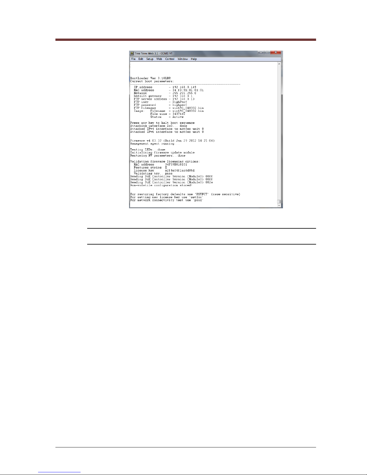
Manageable Mosaic switch Installation and User Guide
Page 46 of 87
Figure 4-2 Hyper Terminal Boot Sequence
NOTE: The actual appearance or values may differ from version to version or per system
configuration
4.1.1 Configuring the IP and Community Parameters
The manageable Mosaic switch unit is shipped with the following defaults:
• DHCP Disabled
• IP Address 192.168.0.100
• Netmask 255.255.255.0
• Default Gateway 192.168.0.1
• TFTP Server Address 192.168.0.7
• Get Community Public
• Set Community Private
• Default password – mypass (case sensitive; Telnet password).
SUMMARY
Page 47

Manageable Mosaic switch Installation and User Guide
Page 47 of 87
1. Enter a Terminal Emulation application as described in previous section.
2. To change password, one need to halt the boot sequence Press any key within the five
second countdown period, in order to enter the configuration mode. The password
prompt appears.
NOTE: If you do not press any key within the five second count down, the firmware loading
will continue and the management agent will start running. In this case, you will need to
start the process again by restart of the manageable Mosaic switch unit.
3. Enter the default password mypass (case sensitive). The prompt Change Password
appears, enabling you to change the default password.
Please enter CLI password - mypass
Change password? [Y/N] – Y
4. Change the password (recommended) by entering Y.
5. Enter a new password (up-to 12 alphanumeric characters). It is recommended to use a
combination of upper and lower case characters.
NOTE: You will be prompted if the password is not within the required format. This
password is also used for Telnet access.
6. Next, the prompt Please enter IP parameters appears, enabling you to configure the
following IP parameters for the SNMP agent: DHCP, IP Address, Netmask and Default
Gateway.
NOTE: Current settings are displayed between squared brackets [ ]. Pressing enter keeps
the current setting and move on to the next line. In order to modify a line, enter the
appropriate information. At the end of this configuration session, the user can choose to
continue by typing C, or to return in order to modify one or more of the previous entries by
typing M.
Please enter IP parameters
IP address [192.168.0.100] -
Netmask [255.255.255.0] -
Default gateway [192.168.0.1] -
Modify the above or continue? [M/C] - C
7. The next configuration session is for boot parameters.
SUMMARY
Page 48

Manageable Mosaic switch Installation and User Guide
Page 48 of 87
Please enter new boot parameters
SNMP get community [public] -
SNMP set community [private] -
TFTP server address [192.168.0.13] -
FTP user [HighPerf] -
FTP password [highperf] -
TFTP filename [wp68x_040104.bin] –
Boot operation [1: Download, 2: Run] – 2
Modify the above or continue? [M/C] - c
You will be prompted to change the SNMP Community String.
The community string is part of any SNMP packet. The SNMP agent does not respond to SNMP
packets whose community string does not match its internal community string. The community string is
an alphanumeric string of up to 15 alphanumeric characters.
SNMP defines different community strings for Get and Set commands. The factory default community
settings of the device are:
• SNMP Get community - public
• SNMP Set community - private
The TFTP prompt appears, enabling to change the TFTP parameters which refer to firmware upgrades.
This is usually necessary at this stage. Consequently, press enter at each of the following prompts.
Refer to Section 7.2 for complete instructions on local and remote firmware upgrade.
Three Boot operation possibilities are available. Option 1 refers to firmware upgrades using TFTP as
described in Section 7. Option 2 allows restart of the unit with the new parameters.
The next step of this final configuration session continues by typing C, or to return in order to modify
one or more of the previous entries by typing M.
The unit restarts with the updated parameters displayed on the screen as follows:
SUMMARY
Page 49

Manageable Mosaic switch Installation and User Guide
Page 49 of 87
Boot operation [1: Download, 2: Run] - 2
Modify the above or continue? [M/C] - c
(Updated parameters appear here)
Storing updated boot record . . . done
Initializing bootloader telnet interface
Copy image to RAM . . . . . . . . . . . . . . . . . . . . . . done
XXX Firmware V2.90.01 (Build Date and time)
Management agent running. . .
Validating firmware licensing options:
MAC address (MAC address)
Features string (add-on features letter(s), such as
“X” for 802.1X))
License key (License key)
Validating key...pass
For restoring factory defaults use ‘RSTFCT’ (case sensitive)
For setting new license key use ‘setlic’
For network connectivity test use ‘ping’
In addition to the updated parameters, the MAC address of the management agent also appears, as
well as the special features and the licensing key for such features, if relevant. Also displayed are three
additional commands: RSTFCT, setlic and ping. These commands, described below, are available any
time via the CLI connection.
4.1.1.1 The RSTFCT Command
The RSTFCT command (reset to factory defaults) is used to restore factory defaults. The command is
case sensitive.
1. Type RSTFCT to reset values to their factory defaults then press enter.
2. The unit restarts according to factory default values.
4.1.1.2 The SETLIC Command
The setlic command is used to activate special features by entering the letter(s) which represents each
feature as well as the appropriate license key. Each feature is identified by a specific letter, and the
SUMMARY
Page 50

Manageable Mosaic switch Installation and User Guide
Page 50 of 87
license is acquired according to the feature string (one license is issued for a string representing
individual or multiple features).
1. Type setlic then press enter.
2. When prompted to enter the features string, type the upper case letter(s)
representing the feature string. For example, X (case sensitive) which is for the
802.1X protocol and then press enter.
3. When prompted, type the License key you received from Legrand then press
enter.
4. When prompted to Modify or Continue, type C to continue.
5. The system will inform you that new license information is being stored. The
manageable Mosaic switch device must be restarted to activate the special
feature. The management application (WizView or Web management) must
also be re-started in order to view and manage the special feature.
4.1.1.3 The PING Command
When connecting the manageable Mosaic switch to the network, or whenever network connectivity
needs to be tested, the integrated ping command can be used.
The network connectivity is tested by typing ping xxx.xxx.xxx.xxx where xxx.xxx.xxx.xxx is the IP
address of the server / device on the network with which connectivity is verified.
It is recommended to run this test at the end of the installation process when the unit is initially
connected to the network.
SUMMARY
Page 51

Manageable Mosaic switch Installation and User Guide
Page 51 of 87
4.2 LAN Configuration via the LCS2 - FTTO Init
Application
4.2.1 Running the LCS2 - FTTO Init application
N order to run the LCS2 - FTTO Init application, double click the program icon to invoke the application.
The following screen is displayed.
Figure 4-3 LCS2 - FTTO Init Discovery screen
Click Start to begin the discovery process.
When the process is complete, the list of discovered devices is displayed.
Figure 4-4 LCS2 - FTTO Init Discovery screen - Discovered Devices
Select the device you wish to configure remotely. The LCS2 - FTTO Init Password prompt
dialog is displayed.
SUMMARY
Page 52

Manageable Mosaic switch Installation and User Guide
Page 52 of 87
Figure 4-5 LCS2 - FTTO Init Password prompt dialog
Type in the default Legrand password: “mypass” and click OK. The LCS2 - FTTO Init
screen is displayed.
Figure 4-6 LCS2 - FTTO Init Main Screen
4.2.2 Configuring the IP and Community Parameters
The manageable Mosaic switch unit is shipped with the following defaults, which can all be changed:
• IP Address 192.168.0.100
• Default Gateway 192.168.0.1
• Subnetmask 255.255.255.0
• DHCP Disabled
• Get Community Public
• Set Community Private
• FTP Server Address 192.168.0.7
• Default password – mypass (The mypass password is case sensitive and applies
to all configuration tools — LCS2 - FTTO Init and Telnet.)
4.2.3 Changing the Password
Change the password used to access a device via LCS2 - FTTO Init as follows:
SUMMARY
Page 53

Manageable Mosaic switch Installation and User Guide
Page 53 of 87
1. On the LCS2 - FTTO Init screen, click the File menu, and choose Change
Password. The following dialog tab is displayed.
Figure 4-7 Changing the LCS2 - FTTO Init password
2. In the Password field, enter your current password. (The default password is
“mypass”).
3. In the New Password and Verify Password fields, enter your new password.
4.3 Default Settings of the manageable Mosaic switch
4.3.1 Restoring manageable Mosaic switch Default Settings
User may restore default parameters at any time through the following ways:
• From Telnet (see Section 8) by typing the Restore Factory command.
From the Web management. (Click the System icon and select the Factory Defaults. Press
the Restore bar).
• Using the LCS2 - FTTO Init application, click the Commands menu and choose
Reset.
• Using the CLI connection, type the RSTFCT command (case sensitive).
The following parameters that may be configured through the CLI won’t be affected
by the restore factory default commands:
• CLI password, IP address, Netmask, Default gateway, SNMP get community,
SNMP set community
• TFTP server address, TFTP filename, Features string, License key. (These
parameters may be configured by CLI and remote management)
SUMMARY
Page 54

Manageable Mosaic switch Installation and User Guide
Page 54 of 87
4.3.2 Changing manageable Mosaic switch Factory Default Settings
The manageable Mosaic switch factory default settings provide the basic switch configuration of port
status and management, in which all ports and management are open and accessible. The factory
default settings may be changed only by technicians (user level: Technician), in cases higher level of
security is required.
The factory default settings can be changed to assign a specific VLAN for management access, and/or
to close all user ports as the factory default, if you choose to enable VLAN secured access through the
uplink port option.
You can change the factory defaults via the Embedded web interface application, or via the LCS2 -
FTTO Init application.
Change factory defaults via Embedded web interface as follows:
1. Log in to the Embedded web interface application as Technician.
2. From the Embedded web interface application menu, click System Config., and
then click the Configuration tab on the System Configuration screen.
Figure 4-8 Changing Factory Defaults via Embedded web interface
• Port Status may be changed from All Open to Uplink Only. If you choose Uplink
Only, the switch and it’s management will only be accessible from the uplink port.
• Mgmt. VLAN is used to disable/enable VLAN filtering to management access
(Default is Disabled), and Mgmt. VID is used to select the management VLAN ID.
SUMMARY
Page 55

Manageable Mosaic switch Installation and User Guide
Page 55 of 87
3. The new factory defaults will be activated after the next Restore Factory Default
command.
4.3.3 Restoring manageable Mosaic switch Factory Default Settings
1. Log in to the LCS2 - FTTO Init application.
2. From the LCS2 - FTTO Init application menu, click Commands, and choose Restore
Factory Defaults. The following prompt is displayed.
Figure 4-9 Restoring Factory Defaults via Embedded web interface
3. Click Yes to restore the device’s factory defaults.
4.3.4 Configuring Active Management Interfaces
Factory defaults configure all three management interfaces (SNMP, Web and Telnet) to be active. This
configuration can be changed for the device to be only managed by one or a combination of two
management interfaces
To configure the management interfaces proceed as follows:
1. From the Embedded web interface main screen, click System Config. The System
Configuration window appears.
2. Click the Config tab of the System Configuration window. The following screen is
displayed.
SUMMARY
Page 56

Manageable Mosaic switch Installation and User Guide
Page 56 of 87
Figure 4-10 Changing Management Interfaces
3. Under Management Interfaces, make another selection from the Services field drop
down list.
Figure 4-11 Changing Management Interfaces-Services
SUMMARY
Page 57

Manageable Mosaic switch Installation and User Guide
Page 57 of 87
5
5
Device Security
Device Security
5.1 Securing Management Access
There are three ways to remotely manage the manageable Mosaic switch device: from the Embedded
web interface application, via any Web browser or Telnet. The manageable Mosaic switch provides
various advanced methods for securing the remote management access. The management access
security features, provided for the different management applications, are listed in the table, below,
Table 5-1 Remote Management Access Security
Methods of Security Management
Embedded
web
interface
Application
Web
Management
Telnet
Community Strings (SNMP)
Get Community and Set Community
strings.
Yes
Yes
--
User Access Levels
Three password protected user access
levels.
Yes
Yes
Yes
(Single level)
Management Access List
Restricts access only to managers whose
IP address is defined on this list (white list).
Yes
Yes
Yes
Management Access Path
Restricts access through either the user or
backbone ports.
Yes
Yes
Yes
VLAN Secured Management
Assigns specific VLAN for management in
order to isolate and secure management
traffic and avoid management flooding by
irrelevant traffic.
Yes
Yes
Yes
Web Management User's Authentication
Authentication of Web management
access via a Radius server (see Section
5.1.7).
-- Yes
--
SUMMARY
Page 58

Manageable Mosaic switch Installation and User Guide
Page 58 of 87
5.1.1 Community String / Passwords
The community string is part of the SNMP packet. The SNMP agent will not respond to SNMP packets
whose community string does not match its internal community string. The community string is an
alphanumeric string of up to 15 alphanumeric characters.
SNMP defines different community strings for Get and Set commands. The factory default community
settings of the device are:
SNMP Get community – public SNMP Set community – private
These community strings may be modified through the CLI or via the Telnet commands: set get
community and set set community (see Section 8).
5.1.2 User Access Levels
The manageable Mosaic switch defines three user access levels: Guest, Administrator and
Technician. For details, see Section 3.1.1 and Section 3.1.2.
5.1.3 Management Access List
The management access list restricts management access only to managers whose IP address is listed
in the device Access List. Up to eight entries can be defined.
When the access list is enabled, the device may be reached only by remote manager(s) whose IP
address is listed in the access list. When the access list is disabled, the device may be reached from
any IP address.
NOTES
The access list may also be managed through Telnet "show/add/delete acl entry"
command (see Section 8).
The access list security cannot be enabled unless the IP address of the active manager
exists on the list.
The IP address of the active manager cannot be deleted as long as the Enable access list
is check-marked.
To define the Management Access List:
1. From the Embedded web interface main screen, click Management and expand the
Access List tab.
SUMMARY
Page 59

Manageable Mosaic switch Installation and User Guide
Page 59 of 87
Figure 5-1 Management menu, Access List tab
2. Click Add, type the IP address of the remote manager’s workstation from which access
will be allowed in the new window and click OK. Repeat for each additional IP address
to be added (up to eight).
3. Verify that the IP address of the active manager (issuing the command) is on the
Access List.
4. From the Enable/Disable list, select Enable.
5. Click Apply and then click Yes in the verification window.
To delete an address select the address from the list and click Delete.
5.1.4 Management Interfaces
Factory defaults configure all three management interfaces (SNMP, Web and Telnet) to be active. This
configuration can be changed so that the device can only be managed by one or a combination of two
management interfaces. To configure the management interfaces proceed as follows:
1. From the Management menu click the Management Interfaces tab to make a
selection from the Services field drop down list.
2. Click Apply
Figure 5-2 Changing Management Interfaces-Services
SUMMARY
Page 60

Manageable Mosaic switch Installation and User Guide
Page 60 of 87
5.1.5 Management Access (Secure NMS) Path
The in-band management path can be secured by limiting the remote access through either user ports,
backbone ports or all ports.
By default, the NMS path is not secured, allowing access from all ports.
To change the Secure NMS Path:
1. From the Embedded web interface main screen, click Management and expand the
Secure NMS Path tab
2. Select the required option from the Path list. The following options are available
• User Ports Only – access is allowed only through the user ports (ports 1-4).
• Backbone Port(s) Only – access is allowed only through the backbone ports (uplink
ports 1-2).
• All Ports – Secure NMS Path option is disabled and access is allowed through all
ports.
NOTE: MGMT VLAN filtering overrules NMS access path.
Figure 5-3 Changing the Secured NMS Path
3. Click Apply.
5.1.6 Securing Management Access via VLAN
Securing management access via VLAN is used to isolate and secure management traffic and avoid
management flooding by irrelevant traffic.
The manageable Mosaic switch enables assigning a dedicated VLAN to the internal management port.
Only frames belonging to that specific VLAN, received from ports belonging to the same VLAN
membership group, can communicate with the management agent.
This type of VLAN configuration provides an additional level of security to the management access.
Assuming the switch operates in 802.1Q VLAN (i.e. the "802.1Q VLAN filtering enable" is checked
(selected), and the "VLAN filtering" is checked (selected) on all the ports) management access will only
be available for the following frames:
• VLAN frames, with VID=4095, arriving from the uplink port.
• Non-VLAN frames arriving from the uplink port (only if the default VID of the uplink port
is also configured to 4095).
If the frame arrives without a VLAN, and the VLAN filtering of this port is selected, the filtering is
according to the configured default VID of the port (4095 in our example)
Any other frame, whether VLAN (with other VID number) or non-VLAN arriving on ports other than the
uplink port, will be filtered, and will not be forwarded to the management agent.
Response frames, transmitted from the internal management agent to the remote manager, are VLAN
frames with VID=4095.
SUMMARY
Page 61

Manageable Mosaic switch Installation and User Guide
Page 61 of 87
5.1.7 Web Management User’s Authentication
Legrand manageable devices can be configured to seek user level password authentication from a
central Radius server, such as from a Freeradius, Winradius or Radiator server, while logging in from a
Web browser. The advantage of storing user level passwords in the Radius server is that if / when the
Web management passwords are changed, they need be changed only in the Radius server and not in
each individual device.
Activating the Web management user authentication, via a Radius server, is described in Section 3.2.1.
5.2 Securing Network Access
The manageable Mosaic switch provides enhanced network security features by introducing advanced
port based network access control. The manageable Mosaic switch supports port based MAC access
security as well as 802.1X port based network access security (optional).
5.2.1 MAC Access Security - Securing User Access to the Network
The MAC access security protects the network from unauthorized "guests" attempting to access the
network through the user ports of the device.
MAC security takes advantage of the automatic learning and aging time of the access switch to
provide MAC level network access security. MAC security operates on active devices, devices that send
out frames to the network on a regular basis like any standard PC, notebook or other workstation. It is
not recommended to use MAC security for a passive device (for instance a printer) since passive
devices do not initiate frame transmissions and therefore are not “learned” automatically by the device.
The MAC security feature is configurable only from the administrator and technician levels. MAC
security has two operation modes, High Security Level and Low Security Level.
5.2.1.1 High Security Level
High security allows only one specific MAC address on the port look-up table. If the port learns
additional or different MAC addresses, the port will immediately be blocked. The port will re-open
automatically only when the permitted device is connected and the aging time has elapsed of all other
MAC addresses. High security ensures single device access to the port.
For example, the network manager can designate the MAC address of an employee's workstation to a
specific port as the only approved address for this port. In this way, the employee's PC has sole use of
that port. If another device connects to that port, the port will block all data transmission.
5.2.1.2 Low Security Level
Low security enables the access of multiple devices to one secured port (or a segment connected to
the port via an additional external switch / hub) as long as one of the devices connected to the port
bears a specified MAC address. When the designated device is connected to the port, the presence of
its specified MAC address on the look-up table of the port opens port access for all the devices on the
SUMMARY
Page 62

Manageable Mosaic switch Installation and User Guide
Page 62 of 87
segment. When that specific MAC address does not exist on the look-up table, the port is blocked to all
the devices.
An example of this is a researcher who has a number of LAN devices (a PC, a printer, a notebook,
testing equipment, etc.) hooked-up to a "local lab segment" connected to the organization's network
through manageable Mosaic switch secured access port. The researcher has assigned his notebook as
the approved address. When low security is enabled, all the devices on the lab segment cannot access
the network unless the researcher’s notebook is connected to the lab segment.
Another example is the company conference room that has a local segment. Visitors may plug into the
segment but it will stay isolated from the network unless a company authorized representative is
present and connected.
NOTE: The Low Security Level blocks data transmission through the port after the aging
time of the approved address has elapsed. It is important to keep this in mind when
configuring the aging time parameters.
5.2.1.3 To Configure MAC Access Security
There are two modes of MAC security:
• MAC Access Security is locally authenticated according to the approved MAC
• The Approved MAC is authenticated by the Radius server before continuing with the
MAC Access Security process.
The MAC security mode is selected only through the Telnet application. See Section 8.5.
Set a locally approved MAC address as follows:
1. In the Embedded web interface main screen, click on the required Port icon.
The Port View window appears. Expand the MAC Security tab.
Figure 5-4 The Port View Window MAC Security tab
MAC Security Configuration Fields:
• MAC Address 1-3 list displays the MAC address entries belonging to that port in the
look-up table.
• Approved MAC field displays the specific MAC address to be secured (the MAC
address according to which the MAC security algorithm works).
• Mode field displays the MAC security operation mode (disabled, low security or high
security).
SUMMARY
Page 63

Manageable Mosaic switch Installation and User Guide
Page 63 of 87
• Status field displays the port security status (disable, port forwarding, or port blocked).
When disabled appears in the Status field, this means that the MAC security is
disabled. When port forwarding or port blocked appears in the Status field, this
means that the MAC security is enabled and that specific port is either forwarding or
blocked in accordance to the MAC security algorithms.
NOTE: Port Monitoring, MAC security and 802.1X cannot be active at the same time.
2. In the Approved MAC list select the MAC address to be designated as the
approved MAC address.
3. Open the Mode list and set the mode according to the following parameter
descriptions:
• Disable – MAC security is not enabled.
• Low Security Level – The port is open (forwards data) for all devices as long as
the approved MAC address exists on the port's look-up table. When the designated
device is disconnected and its MAC address is removed from the port table, the
port blocks data communication to all devices.
• High Security Level – Only the designated approved MAC address can use the
port (i.e., only the approved MAC address exists on the port’s look-up table). If the
port receives frames from another device (other addresses in the look-up table),
then the port blocks all data transmission, even for the approved address.
NOTE: When a port is blocked through MAC Security it is detected as a major event and
an appropriate trap is sent to the authorized SNMP managers.
5.2.2 802.1X Port Based Network Access Security
5.2.2.1 General Description
Three components, illustrated in Figure 5-5, are required to create an access authentication scheme
based on 802.1X standards:
SUMMARY
Page 64

Manageable Mosaic switch Installation and User Guide
Page 64 of 87
Figure 5-5 802.1X Access Authentication Scheme
The 802.1X Supplicant workstation is the device that needs authentication in order to access the
network. This device must have operational 802.1X Supplicant service. Consult the network
administrator to assure that the 802.1X Supplicant is installed and properly configured on the
workstation(s).
Upon connecting the workstation to an 802.1X enabled port in the manageable Mosaic switch, the Local
Area Connection log-in window should appear to enable the user to log-in to the network. Devices
which do not have 802.1X Supplicant service will not be able to access the network.
The Authenticator (manageable Mosaic switch) is the device performing the 802.1 X port access
securities and controlling access to the network. The Authenticator invokes the 802.1X Supplicant on
the workstation and waits to receive the login information from the user. After receiving the login
information the Authenticator checks with the Authentication Server and performs the necessary action
(block or permit) based on the results received from the Authentication Server. The Authenticator uses
RADIUS (Remote Authentication Dial-in User Service) to communicate with the Authentication Server
(such as, Freeradius, Winradius or Radiator servers). The Authenticator (manageable Mosaic switch
should be configured with the Authentication Server address and shared password in order to enable
communication between them.
The Authentication Server is a central network device which maintains the login information of
permitted users. The Authentication Server validates the username and password information of the
client and instructs the Authenticator whether or not to block or permit network access to each specific
client.
5.2.2.2 Defining the Radius Server via Telnet
1. From the Windows Start Menu select Run and type Telnet then the IP address of the
manageable Mosaic switch device.
2. At the prompt, enter the default password, mypass (case sensitive) or the new Telnet
access password you may have defined.
802.1 X Supplicant clients
Authenticator
Authentication Server
SUMMARY
Page 65

Manageable Mosaic switch Installation and User Guide
Page 65 of 87
NOTE: If you type show radius the Server IP address will be displayed followed by the
Shared secret hidden by *** (three asterisks). The factory default for the Server IP address
is 1.2.3.4 and the Shared secret is *** (three asterisks).
1. At the prompt, type Set radius server [your radius server’s IP address].
2. At the prompt, type Set radius secret [your shared key password with the Radius
Server].
NOTE: You must enter your shared key password since there is no active default
password. The Radius server definitions are not maintained in the RSTFCT (restore factory
default) command.
3. Type Logoff.
NOTE: You can configure manageable Mosaic switch manageable devices to have their
Web access passwords authenticated by the Radius server. In order to do this, use the
Telnet command set http password radius (see Section 8).
5.2.2.3 Activating the 802.1X Authentication Security Protocol
Figure 5-6 Port View Window, 802.1X Tab
The 802.1X tab includes the following fields:
• Mode: Selection box that allows choosing between Enable and Disable.
• Supplicant Addr.: MAC Address of the device connected to the port.
• Status: Text description of the current 802.1X status of the port.
• User Name: Displays the Logon Domain followed by the User Name as entered by
the user on the supplicant device connected to the port.
• Pae State: States the current 802.1X machine status information.
• Backend State: States the current 802.1X machine status information.
• Restart: Restarts / Refreshes the authentication process on the authenticator and thus
also on the supplicant.
5.2.2.4 Enabling the 802.1X Authentication Security Protocol
Now that the Radius Server has been defined and the 802.1X Security Protocol has been installed and
can be managed, the next step is to enable the 802.1X port based network access on the desired
port(s). In the Embedded web interface main screen, click the desired Port to access the Port View
window.
SUMMARY
Page 66

Manageable Mosaic switch Installation and User Guide
Page 66 of 87
1. From the Port View window, expand the 802.1X tab.
2. Click the Mode list and select Enable.
3. Click Apply and in the confirmation window click Yes.
Repeat this procedure for each required port. The 802.1X Authentication Security Protocol is now
enabled on the desired port(s). The management application will show a “lock” icon on the secured
port(s).
Port 1 in Figure 5-7 marked with the red lock specifies that the port is already enabled but not yet
authorized by the Authentication Server. Once, Authentication Server authorized the port the lock
icon will change its color to green.
Figure 5-7 802.1X Access Authentication Enabled icon
5.2.3 Secure HTTP Protocol (HTTPS)
5.2.3.1 General Description
Hypertext Transfer Protocol Secure (HTTPS) is a combination of the Hypertext Transfer Protocol with
the SSL/TLS protocol to provide encryption and to secure identification of the server. HTTPS
connections are often used for sensitive transactions in corporate information systems. HTTPS aims to
create a secure channel over an insecure network. This ensures reasonable protection from
eavesdropping and man-in-the-middle attacks, provided that adequate cipher suites are used and that
the server certificate is verified and trusted.
The trust inherent in HTTPS is based on major certificate authorities that come pre-installed in the Web
browser software. This essentially permits a certificate authority (e.g. VeriSign, Microsoft, etc) to
determine trusted sources.
SUMMARY
Page 67

Manageable Mosaic switch Installation and User Guide
Page 67 of 87
5.2.3.2 Enabling HTTPS
Figure 5-8 HTTPS Enabled icon
SUMMARY
Page 68

Manageable Mosaic switch Installation and User Guide
Page 68 of 87
6
6
Monitoring and Analysis
Monitoring and Analysis
The manageable Mosaic switch provides monitoring and analysis functions on both device and port
level:
• Device level – The device stores the last 64 events. The event display can be filtered
according to user defined criteria. The system reports three levels of events: notify, minor and
major. Major events will have the words Major and the menu title Events marked in red. Events
may be acknowledged by an Administrator or Technician level user. Only events occurring on
the network ports of the device are recorded. Configuration changes that are initiated by the
network manager are not considered events. Events can also be transmitted, as SNMP Traps,
to additional managers by adding their IP address to the device’s SNMP Trap Destination list.
• Port level – Monitoring and analysis includes port specific RMON and statistics counters and
port monitoring (mirroring) viewing valid data of one port on another user defined port.
6.1 Configuring SNMP Trap Destinations
When a system event is detected, the device sends a trap to a list of authorized SNMP managers. The
list of managers is configured through the management application.
NOTE: The Trap destination list may be configured through Web, Telnet and Embedded
web interface. Only Administrator or Technician level are allowed in Embedded web
interface to configure te Trap destination table
To configure the SNMP Traps destination addresses:
1. .From the Embedded web interface main screen, click Management icon tab
2. Select the Trap Destination tab and click Add bar
3. In the IP Address box, enter the destination IP Address to which traps generated by this
device will be sent. Click OK. The address will appear in the IP Address list.
4. Repeat for each additional IP Address.
Figure 6-1 Management menu, SNMP Traps tab
NOTE: To remove a traps destination address, select the address and click Delete.
SUMMARY
Page 69

Manageable Mosaic switch Installation and User Guide
Page 69 of 87
6.2 Device Level – Event Log
6.2.1 Viewing Recorded Events
The last 64 events are stored in the device and are available for display at any time through the Event
Log window, located at the bottom of the Embedded web interface main screen. The Event list is
cleared when turning on or resetting the device.
When a management application is continuously managing the device, an unlimited number of events
are displayed for the currently managed device. If the management application disconnects from the
device and reconnects, only the last 64 events that are stored in the device are uploaded to the Event
Log.
Only events occurring on the network ports of the device are recorded. Configuration changes that are
initiated by the network manager are not considered events.
The viewed events may be acknowledged and filtered according to various user defined criteria. The
events recorded are:
Major Events:
• Device voltage: changes that exceed the thresholds and return to limits.
• Internal temperature of the device: changes that exceed the thresholds and return to
normal.
NOTE: Thresholds levels may be modified by technician level access.
• Port Locked due to security definitions: when an unauthorized MAC address connects
to a MAC Secured port.
Minor Events:
• There are currently no events defined as Minor in the manageable Mosaic switch.
Notify Events:
• Change in Port status: Link up, Link down.
• System startup
To get a full view of the Event Log window user need to click the arrow on its top right
corner.
Figure 6-2 Event Log window
SUMMARY
Page 70

Manageable Mosaic switch Installation and User Guide
Page 70 of 87
Each trap notification consists of:
• A unique index number
• Event date and time stamp
• Event description
• Event source
• Severity (notify, minor, major)
• Acknowledge (yes or no)
Event Levels and Color codes:
The record is colored according to its severity:
• Notify (cyan)
• Minor (yellow)
• Major (red)
To Sort information:
From the Event Log window, click any header to sort the information according to the
selected header in ascending or descending order.
To acknowledge events:
From the expanded Event Log window, select the requested event(s) in the table and
click the Ack on the bottom right.
NOTE: Only Administrator or Technician level users can acknowledge events.
6.2.2 Event Filter
Figure 6-3 Event log with the Event Filter window
SUMMARY
Page 71

Manageable Mosaic switch Installation and User Guide
Page 71 of 87
Events may be filtered according to different parameters and can help the network manager focus on
specific events.
The filter operates according to the following parameters: Dates, Time, Port Number, Severity and
Acknowledged / Unacknowledged events.
To filter the displayed events:
1. From the Embedded web interface main screen, click the arrow in the Event
Log to enlarge displayed data
From the Event Log window click Filter.
The Events Filter window appears as shown in Figure 6-3
Figure 6-3
2. Check the box for each parameter you wish to include in the filter (Date,
Severity and/or Source) and define the appropriate filter parameters.
NOTE: Unchecked Filters will result in displaying all the events related to that filter.
3. In the Acknowledgement area, select either Acknowledged or Not
Acknowledged to filter events according to the parameters as required.
NOTE: When neither check box in the acknowledge area is checked, both Acknowledged
and Not Acknowledged events are displayed.
4. Click OK to enable the filter definitions.
6.3 Port Level Statistics and RMON Counters
RMON (Remote Network Monitoring) provides standard information that can be used to monitor and
analyze port traffic from a central site.
The manageable Mosaic switch supports RMON RFC 2819 (which supersedes 1757 and 1217)
Ethernet statistics group.
SUMMARY
Page 72

Manageable Mosaic switch Installation and User Guide
Page 72 of 87
In addition to RMON information, statistics for RX packets and counters for TX packets can be
monitored for each port.
To display the port RMON information, RX statistics and TX counter:
1. From the Embedded web interface main screen, click the icon of the Port of interest.
The Port View window appears.
2. From the Port View window, select the Statistics tab.
NOTE: Click Reset to ZERO all counters.
Figure 6-4 Port Statistics and Counters
6.4 Port Monitoring
The port monitoring feature enables analyzing and recording valid data on a port by mirroring its traffic
to another, user allocated (monitoring destination) port. User may monitor the egressing, or both
ingressing and egressing data of any port. This feature can be used for network analysis as well as
recording port traffic.
More than one port can be monitored on a single monitoring destination port. To assure the integrity of
the monitored data and since the monitoring port bandwidth is limited to 100Mbps, flow control is
automatically activated on the monitored port(s) when the monitored traffic exceeds 100Mbps.
To configure port monitoring:
1. From the Embedded web interface main screen, click on the icon Port to be
monitored. The Port View window appears.
2. From the Port View window, click Monitor tab.
SUMMARY
Page 73

Manageable Mosaic switch Installation and User Guide
Page 73 of 87
Figure 6-5 Port View window, Monitor tab
3. Select the Port Monitoring Mode from the Mode list described in the following
table:
Table 6-1 Port Monitoring Mode Options
Option
Description
None
Port monitoring mode not enabled.
Egress Only
Only egress frames are copied to the destination port.
When the device is reset, the monitoring mode resets to
None.
Egress & Ingress
Egress and ingress frames are copied to the destination port.
When the device is reset, the monitoring mode resets to
None.
NV Egress Only
Only egress frames are copied to the destination port.
Mode remains on after system reset.
NV Egress & Ingress
Egress and Ingress frames are copied to the destination port.
Mode remains on after system reset.
4. Select the destination port from the Destination list and click Apply.
SUMMARY
Page 74

Manageable Mosaic switch Installation and User Guide
Page 74 of 87
7
7
Updating Firmware Versions
Updating Firmware Versions
7.1 General
The manageable Mosaic switch firmware comprises three elements, each updated separately:
• Image – SNMP Agent software
• Content – Java Applet (Web management interface)
• Configuration – Configuration file
The firmware may be updated as follows:
• Locally (CLI) through a serial connection (Section 7.2)
• Via the LCS2 - FTTO Init Remote Device Configuration application for devices supplied
without the CLI cable
• Remotely through the Embedded web interface Remote Firmware Update
7.2 Local (CLI) Firmware Update
Update the firmware locally through a serial connection as follows:
1. Launch a terminal emulation application.
2. Connect the CLI serial cable to the manageable Mosaic switch switch.
3. Modify the SNMP Get / Set Community parameters (if necessary).
4. Update the IP address of the TFTP server that will be used to download new TFTP
software versions to the device.
5. Update the TFTP filename of the new software version to be downloaded to the device.
6. The prompt Boot operation [1: Download image, 2: Download content, 3: Run] appears,
enabling to download a file to the device or to continue.
Enter 1: Download image to download / update the SNMP agent of the
manageable Mosaic switch file with a .bin extension (for example: w56x_290_01.bin).
Enter 2: Download content to download / update the Web management applet of the
manageable Mosaic switch file with a .con extension (for example: w5xx_282.con).
NOTE: Since each file downloads separately, after downloading one file, repeat steps 5
and 6 in order to download the other file.
7. After downloading / updating the image and content files (this may take a few minutes)
the user is prompted to enter new boot parameters. Enter new parameters or press
Enter to accept the existing parameters. At the Boot operation prompt, chose 3: Run in
order to reboot the system with the updated files.
Now the unit restarts operations according to the updated files and parameters.
SUMMARY
Page 75

Manageable Mosaic switch Installation and User Guide
Page 75 of 87
7.3 Remote Firmware Update via LCS2 - FTTO Init
1. Launch the LCS2 - FTTO Init application.
2. Modify the SNMP Get / Set Community parameters (if necessary).
3. Update the IP address of the TFTP server that will be used to download new TFTP
software versions to the device.
4. Update the TFTP filename of the new software version to be downloaded to the device.
5. From the File Command list, select the desired command (Download image or
Download content), and monitor the download/upload process in the Process and
Status fields.
Figure 7-1 LCS2 - FTTO Init screen, Firmware Update commands
SUMMARY
Page 76

Manageable Mosaic switch Installation and User Guide
Page 76 of 87
7.4 Remote Firmware Update via Embedded web interface
Figure 7-2 File Operations Window
1. From the Embedded web interface main screen, click on Files. The Files window
appears as shown in Figure 7-2.
2. In the File Server tab update the IP address of the File Server that will be used to
download new firmware versions to the device (The specified IP must have a running
TFTP server program).
3. In the Operation tab update the file name of the new firmware version to download to
the device.
4. Select the desired operation from the Command list. Be sure to match the file type with
the command (.bin with Download Image, .con with Download Content).
NOTE: In order to perform a download or upload operation, the Command being executed
must be colored blue, indicating a changed setting. Clicking apply without changing the
Command, even if it was set in advance to your desired setting, will not proceed with the
command.
5. While downloading / updating the image and content files (this may take several
minutes) the Status field will change depending on the current operation being
executed. At the end of the process, that field will update again to announce the
successful or failed update.
NOTE: Since each file downloads separately, after downloading one file, repeat steps 5
and 6 in order to download another file.
SUMMARY
Page 77

Manageable Mosaic switch Installation and User Guide
Page 77 of 87
7.5 LCS2 - FTTO Bulk Firmware Update
LCS2 - FTTO Bulk is a remote firmware update software that allows updating multiple
devices simultaneously, without the need to manually connect to each device.
Updating firmware using the LCS2 - FTTO Bulk software:
1. From the LCS2 - FTTO Bulk screen, click on the Source tab.
Figure 7-3 LCS2 - FTTO Bulk Source screen
2. In the File Server area, update the server IP address, the username and password
used to connect to the server and the maximum number of devices that may
connect to the server simultaneously (Max Parallel Sessions).
3. In the Download Commands area, check the types of files to be downloaded to the
devices (upload not available through LCS2 - FTTO Bulk) and list the file names to
be downloaded.
4. If a reset operation is required for each device, check the Reset checkbox to
automatically reset each device after a successful download.
5. Click the Targets tab.
SUMMARY
Page 78

Manageable Mosaic switch Installation and User Guide
Page 78 of 87
Figure 7-4 LCS2 - FTTO Bulk Targets screen
6. In the Auto Discovery area, enter a Start IP and End IP. The devices to be
updated must be in that IP range (For example, to update to update three devices
ending in 151, 152 and 153, set the Start IP as 151 and End IP as 153).
7. User need to make sure the GET Community and SET community fields match the
ones used by the user devices (The default GET Community is "public" and the
default SET Community is "private").
8. In the Targets area, select all the devices to be updated from the list. Use shift
click and ctrl click to select multiple devices.
9. Click on the Schedule tab
Figure 7-5 LCS2 - FTTO Bulk Schedule screen
10. In the Start Time area select immediately to begin the update process as soon as
possible, or select Delayed and set a date and time to delay the update until that
time.
SUMMARY
Page 79

Manageable Mosaic switch Installation and User Guide
Page 79 of 87
11. In the End Time area select as necessary to allow the update process to take as
long as needed to complete, or select Limited and set a date and time to stop the
abort the update process if it continues past that time.
12. Click the Status tab.
Figure 7-6 LCS2 - FTTO Bulk Status screen
13. To begin the update process (or wait until the Delay time has been reached), click
Start.
14. The Progress area displays information regarding which device is being updated
at the moment, update status, update progress, time at which the update started,
and an estimated time at which the specific update will complete.
15. When the update process is complete, if Reset is selected, each device will restart
itself automatically.
7.6 Firmware Licensing (in order to activate optional features)
Special add-on features can be purchased separately from Legrand. To activate the feature(s) you need
to acquire an activation key from Legrand and install it on the device through the Firmware licensing
tab.
Each add-on feature is represented by a single letter. Multiple features can operate simultaneously.
When a firmware license key code is assigned by Legrand, it will be a single code that covers all the
add-on features (existing ones as well as new features being added).
When the firmware license for a specialized feature is purchased, the feature is activated by inputting
the license key code. In order to generate the license key, the Legrand representative will require the
MAC address of the device, as well as previously purchased add-on features (if any).
The MAC address of the device is listed in the Inventory tab of the System View window.
SUMMARY
Page 80

Manageable Mosaic switch Installation and User Guide
Page 80 of 87
Figure 7-7 System Configuration window, General tab
1. From the Embedded web interface main screen, click System. The System View
window appears.
2. From the System View window Inventory tab find the MAC Address of your
device.
NOTE: Each feature is represented by a single letter which is case sensitive.
3. Supply Legrand Representative with the MAC Address exactly as it appears in the
Inventory tab and Feature(s) already installed on device, as well as the special
add-on feature(s), to be purchased.
4. Legrand Representative will supply with the feature letter(s) and a license key
code which activates the old feature(s) (if any) plus the new feature(s) being
purchased.
7.6.1 Activating the Special Add-on Feature(s) License Key
After receiving the feature letter(s) and licensing key from Legrand Representative (as explained in
the previous section) activate the feature(s) via the Embedded web interface or Web management
application as explained below:
1. Login to the Embedded web interface or Web management application as a
Technician or Admin.
2. From the Embedded web interface main screen, click Management. The
Management window appears.
3. From the Management window, License tab, Click on the Features field and type the
letter(s) for each licensed feature as given by Legrand representative.
NOTE: The letters are case sensitive and should be entered as a string without any
intervening spaces or punctuation.
4. Click on the Key field and enter the license key exactly as received it from Legrand
Representative (it is recommended to cut-and-paste the license key to avoid font and
case problems) then click Apply.
Figure 7-8 Firmware License Tab
SUMMARY
Page 81

Manageable Mosaic switch Installation and User Guide
Page 81 of 87
Both the manageable Mosaic switch device and the management application (Embedded web
interface or Web management) must be restarted to activate and manage the special add-on
feature(s).
Note: it is recommended to confirm that the new add-on feature(s) have been properly
activated, by referring to new tabs relevant to the new features through the management
applications. (Embedded web interface and Web management, following the restart step)
If the validation key indicates fail, then re-check the feature string and license key and re-start the key
activation process. If the validation key still does not pass, please contact the Legrand Representative.
SUMMARY
Page 82

Manageable Mosaic switch Installation and User Guide
Page 82 of 87
8
8
Telnet
Telnet
8.1 General
Telnet enables remote management of a single IS-2 unit as well as remote configuration of any number
of units by running Telnet script files created for that purpose.
8.2 Run Telnet
1. From the PC Start menu, type Run Telnet followed by a space and then the IP
address of the target device (exact syntax according to the operating system).
or
From a telnet client application, connect using telnet protocol to the IP address
of the target device (Note: when using PuTTY, the password can be rejected
even if entered correctly. In that case, please make sure to make the following
change in PuTTY configuration ➨ Terminal :
Local Echo: Off and Local line editing Off).
2. At the prompt, enter the current password (mypass is the factory default); the
password is case sensitive. If the password is rejected, please see the specific
note for PuTTY in 6.2, 1).
The device prompt, ‘>’ appears. The device is ready to receive Telnet
commands (see Figure 8-1).
Note: The Telnet password can only be changed through the local CLI (serial)
connection.
8.2.1 Invoking Telnet Help
• To view the list of available commands, type ? or help and press Enter.
• To invoke help on a specific command, type the command, followed by a space and ?
Figure 8-1 illustrates the list of available Telnet commands. Figure 8-2 illustrates an example of help on
specific command
SUMMARY
Page 83

Manageable Mosaic switch Installation and User Guide
Page 83 of 87
Figure 8-1 Telnet Commands
IS 2> set port ?
Usage:
set port port_num on|off|10|100|hdx|fdx|an|man
set port port_num flowcontrol on|off
set port port_num egtagins|egtagrem|ingtagrem on|off
set port port_num vlanfilter|egdoubletag on|off
set port port_num name new_name
set port port_num vid default_vid
Examples:
set port 2 fdx - change port 2 duplex mode to full-duplex
set port 1 egtagrem on - enable VLAN tag removal on port 1 egress
set port 2 egdoubletag on - enable double tagging on port 2 egress
set port 4 name Greg_laptop - change port 4 name to Greg_laptop
set port 3 vid 1160 - change default VID of port 3 to 1160
Figure 8-2 Telnet Help on specific command
8.3 Selecting the static IP address of the device
The static IP address used to manage the device cannot be updated using the web interface. In order to
perform this configuration change, it is necessary to connect to the device using telnet. For more
information about how to connect to the CLI using telnet, please refer to "6.2 Run Telnet" Once
connected to the CLI, you can select the IP parameters of the device by using the following command:
set ip params <ip_address> <netmask> <default_gw>
Once the configuration has been changed, it will be effective after the next reboot
SUMMARY
Page 84

Manageable Mosaic switch Installation and User Guide
Page 84 of 87
8.4 Changing User Level Passwords via Telnet
1. From the Start menu, type Run Telnet followed by a space then type the IP
address of the target device (exact syntax according to the operating system).
2. At the prompt, enter the current password (mypass is the factory default); the
password is case sensitive. The device prompt, > will appear. The device is
ready to receive Telnet commands (see Figure 8-1).
3. Type the command set http password followed by a space and any of the
user level access words to change (tech, admin, or guest) and then followed
by another space and the new password to assign to that user level, and then
press enter. A user level password has now been changed. Changing
passwords for one user level does not affect the other user level passwords.
For example, changing the password tech to tech1 will use the following
command: set http password tech tech1
NOTE: You can type show http password followed by a space and a question mark (?) in
order to see what the current user level passwords are.
For security reasons, the Telnet session will automatically terminate if there is no Telnet activity for
approximately 60 seconds.
8.4.1 Defining the Radius Server via Telnet
1. From the Start menu, type Run Telnet and click OK. At the Telnet prompt, connect to
the target device by typing its IP address (exact syntax according to the operating
system).
2. At the prompt, enter the current password (mypass is the factory default); the
password is case sensitive. The device prompt, > will appear. The device is ready to
receive Telnet commands.
3. Type the command set http password followed by the word radius. The response “User
authentication changed to Radius server interface” will appear. Proceed with the
following Telnet commands, as required:
• To display and verify the http password status you can type show http password.
• Using the show radius command, verify that the Radius server is properly configured (see Section
5.2.2.2).
• On the Radius server verify that the correct Radius secret is defined and that passwords are
assigned to the three user access levels.
For security reasons, the Telnet session will automatically terminate if there is no Telnet activity for
SUMMARY
Page 85

Manageable Mosaic switch Installation and User Guide
Page 85 of 87
approximately 60 seconds. To resume the Telnet session you must re-connect and log in again.
To redirect a Legrand manageable device to check management access passwords locally rather than
via the Radius server:
• Type the Telnet command set http password followed by any of the user level access words
(tech, admin, or guest) and then the new password (****) you want to assign to that user level.
This will change the password for that particular user level, as well as restore the last passwords
assigned to the other two user levels (see Section 0).
8.5 Changing MAC Security via Telnet
The following Telnet commands are used to set MAC security parameters:
• set http password radius — The login password is determined by Radius server
settings
• set http password radius mac — The Radius server checks that the approved
local MAC address is listed on the Radius Server
Use the following Telnet commands to return to the default settings:
• set http password Technician tech
• set http password Admin admin
SUMMARY
Page 86

Manageable Mosaic switch Installation and User Guide
Page 86 of 87
Index
802.1Q VLAN .................................................36
Membership................................................38
Port Configuration.......................................39
Setup ..........................................................37
802.1X ....................................61, 63–66, 63–66
Access List....................................................58
Address Migration...........................................37
Aging Time ...............................................61, 62
Authentication Server ...............................64, 66
Auto-Negotiation.............................................20
Boot Sequence .............................................46
Default
Change .................................................54, 55
Parameters ...........................................46, 52
Event Filter .....................................................70
Event Log .................................................68–71
HiView/B Main Screen....................................28
Color Indications.........................................30
HTTPS Protocol..............................................66
IEEE 802.1d Standard......................................8
Internet Protocol (IP) Address ........................45
Learning Time.................................................61
LEDs...............................................................28
MAC Access Security...................61–62, 61–62
Configuration ..............................................62
High Security Level.....................................61
Low Security Level .....................................61
Management
Remote Management Options ...................12
Management Access List ............................... 58
Management Access Path .............................60
Secure NMS Path....................................... 60
Monitoring and Analysis.................................68
Passwords
Community String...............46, 52, 58, 74, 75
User Name .................................................14
Platforms ........................................................ 14
Port
Port Monitoring...........................................72
Port Name ..................................................18
RMON ..................................................68, 71
Statistics.....................................................71
Power over Ethernet (PoE) ............................22
QOS ...............................................................26
Rate Limit ................................................... 27
Radius Server.........................15, 16, 61, 64, 84
Rate Limit ....................................................... 26
Remote Software Reset.................................36
RMON ......................................................68, 71
SNMP Trap.....................................................68
Software Update
Remote..................................... 74, 75, 76, 77
Spanning Tree................................................42
Telnet .......................................................82–83
VLAN
VLAN Secured NMS...................................60
Before configuring your device, please download the latest firmware from the following website
http://www.wifi.legrandelectric.com and update your device with this firmware.
Warning: for Telnet configuration please read chapter 8 “Telnet” before connecting.
SUMMARY
Page 87

Manageable Mosaic switch Installation and User Guide
Page 87 of 87
 Loading...