

Page 1
Archimod HE 240-480®
Installation and maintenance manual
Item LE09392AA-12/16-01 CT
Page 2
2
EN
ENGLISH 3
Archimod HE 240-480®
Page 3

Archimod HE 240-480®
3
Installation and maintenance manual
1 Introduction 5
1.1 Purpose of the manual 5
1.2 Symbols in the manual 5
1.3 Where and how to keep the manual 6
1.4 Update of the manual 6
1.5 Manufacturer’s liability and guarantee 6
1.5.1 Guarantee terms 7
1.6 Copyright 7
2 Safety Regulations 8
2.1 General notes 8
2.2 Denitions of “Skilled Technician” and “Operator” 8
2.2.1 Skilled Technician 8
2.2.2 Operator 8
2.3 Personal Protective Equipment 9
2.4 Hazard signs in the workplace 9
2.5 Signs on the equipment 10
2.6 General warnings 10
2.7 How to proceed in an emergency 12
2.7.1 First-aid procedures 12
2.7.2 Fire procedures 12
3 Models 13
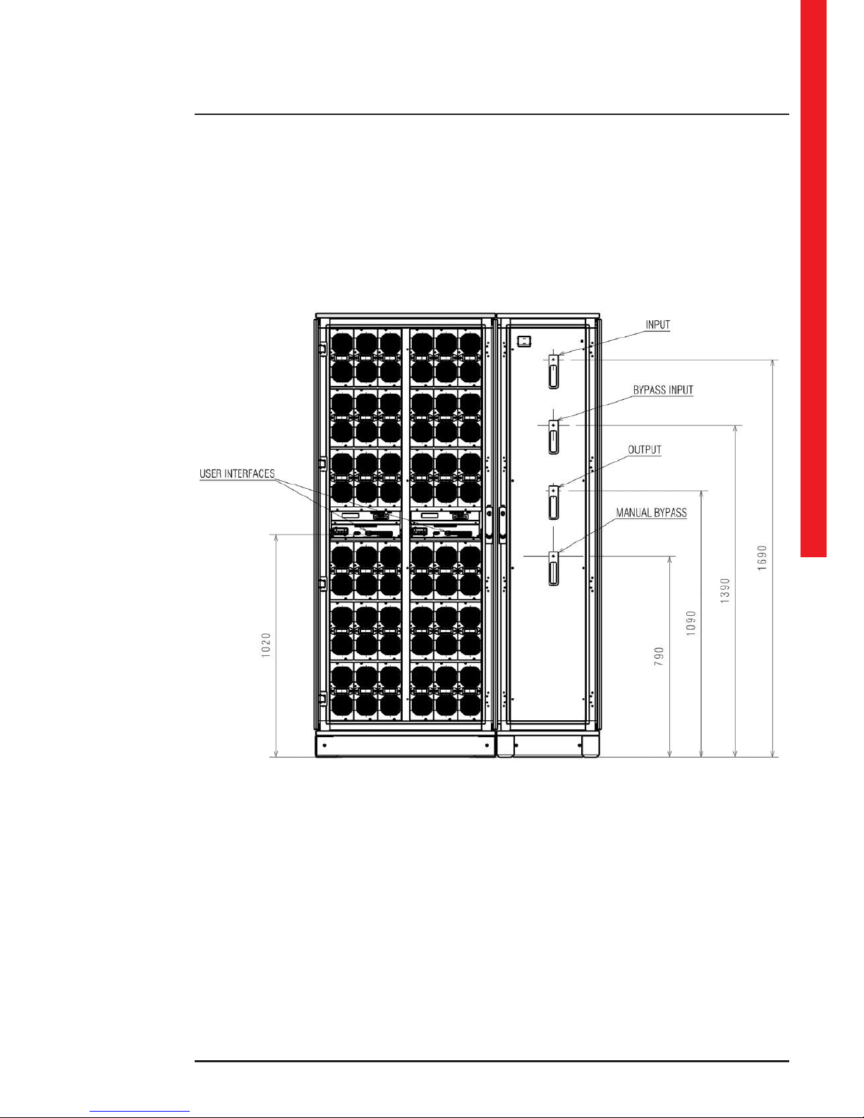
3.1 Archimod HE 240 13
3.2 Archimod HE 480 17
4 Installation 21
4.1 Safety Regulations 21
4.2 Electrical connections 21
4.2.1 Safety warnings 22
4.2.2 Preliminary operations 22
4.2.3 Connection of the cabinets Archimod HE480 22
4.2.4 Cabling 29
4.2.5 Earthing 30
4.2.6 Protective devices 30
4.2.7 Backfeed protection 30
4.2.8 External battery unit installation 32
4.2.9 Mains connection 35
4.2.10 Bypass input line connection 38
4.2.11 Output line connection 40
4.2.12 ARBC (Auxiliary Remote Bypass Contact) 43
4.3 Insertion of power modules 43
Contents
Page 4

4
4.4 Communication devices 44
4.4.1 Description 44
4.4.2 RS232 serial ports 45
4.4.3 Relay Interface 46
4.4.4 Emergency Power O (EPO) 47
4.4.5 Logic level interface 48
4.4.6 Network card (SNMP) slot 49
5 Configuration and Start-up 50
5.1 Introduction 50
5.2 Input configuration 50
5.3 Output conguration 50
5.4 Pre-start-up checks 50
5.5 Start-up procedure 52
5.6 ECO MODE setup 54
5.7 EMERGENCY POWER SYSTEM (EPS) MODE setup 54
6 Maintenance 55
6.1 Introduction 55
6.2 Preventive maintenance 55
6.3 Periodical checks 55
6.4 Ordinary maintenance 56
6.4.1 Power module hot-swap replacement or inclusion of new modules 56
6..4.2 Maintenance procedure for the UPS in maintenance bypass mode 59
6.4.3 Maintenance procedure with UPS off 61
6.5 Replacing the fuses and surge arrester (DIN busbar) 61
6.6 Requirements for external battery units 62
6.7 Extraordinary maintenance 62
7 Warehousing 63
7.1 UPS 63
7.2 Batteries 63
8 Dismantling 64
8.1 Batteries disposal 64
8.2 UPS dismantling 64
8.3 Electronic component dismantling 64
9 Technical data 65
10. Tables 69
Contents
Page 5

Archimod HE 240-480®
Installation and maintenance manual
5
1. Introduction
CAUTION
The instructions in this manual are intended for a SKILLED TECHNICIAN (paragraph 2.2.1).
1.1 Purpose of the manual
The purpose of this manual is to provide the skilled technician with instructions for safely installing the ARCHIMOD HE
240-480 UPS, also called “equipment” in the rest of the manual, and carry out ordinary maintenance procedures.
Extraordinary maintenance operations are not dealt with in this manual because they are the sole preserve of LEGRAND’s
Technical Support Service.
The reading of this manual is essential but does not substitute the skill of the technician who must have received adequate
preliminary training.
The intended use and configurations envisaged for the equipment and shown in this manual are the only ones allowed
by the Manufacturer. The equipment must not be installed differently from the instructions provided.
Any other use or configuration must be previously agreed with the Manufacturer in writing and, in this case, the written
agreement will be attached to the installation and user manual.
This manual also makes reference to laws, directives and standards that the skilled technician is required to be aware of
and consult.
The original text of this publication, drafted in Italian, is the only reference for the resolution of disputes of interpretation
linked to translations into other languages.
1.2 Symbols in the manual
Some operations are shown in graphic symbols that draw the attention of the reader to the danger or the importance
they imply:
DANGER
This indication shows a danger entailing a high degree of risk that, if not avoided, will lead to death or serious injury or
considerable damage to the equipment and the things around it.
WARNING
This indication shows a danger entailing a medium degree of risk that, if not avoided, could lead to death or serious injury
or considerable damage to the equipment and the things around it.
CAUTION
This indication shows a danger entailing a low level of risk that, if not avoided, could lead to minor or moderate injury or
material damage to the equipment and the things around it.
INDICATION
This text includes important information which should be read carefully.
Page 6

6
1.3 Where and how to keep the manual
This manual must be kept in a safe, dry place and must always be available for consultation exclusively by the skilled
technician.
It is recommended to make a copy of it and file it away.
If information is exchanged with the Manufacturer or the authorised assistance personnel, it is essential to refer to the
equipment’s rating plate data and serial number.
INDICATION
The manuals provided are an integral part of the equipment and must therefore be kept for its entire lifetime.
In case of need (for example in the case of damage that even partially compromise its consultation) the skilled technician
is required to get a new copy from the Manufacturer, quoting the publication code on the cover.
1.4 Update of the manual
The manual reflects the state of the art when the equipment was put onto the market. The publication conforms with the
standards current on that date. The manual cannot be considered inadequate when new standards come into force or
modifications are made to the equipment.
Any addition to the manual the Manufacturer considers appropriate to send to the users, must be kept together with the
manual of which they will become an integral part.
The version of the manual updated to its latest release is available on the Internet at http://www.ups.legrand.com
1.5 Manufacturer’s liability and guarantee
The skilled technician and the operator shall scrupulously comply with the precautions indicated in the manuals. In
particular they must:
- always work within the operating limits of the equipment;
- always carry out constant and careful maintenance through a skilled technician who complies with all the procedures
indicated in the maintenance section.
The Manufacturer declines all indirect or direct responsibility arising from:
- failure to observe the installation, maintenance instructions and use of the equipment which differs from the
specifications in the user manual;
- use by personnel who have not read and thoroughly understood the content of the user manual;
- use that does not comply with the specific standards used in the country where the equipment is installed;
- modifications made to the equipment, software, functioning logic unless they have been authorised by the Manufacturer
in writing;
- repairs that have not been authorised by the LEGRAND Technical Support Service;
- damage caused intentionally, through negligence, by acts of God, natural phenomena, fire or liquid infiltration.
Transfer of the equipment to others also requires the handing over of all the manuals. Failure to hand over the manuals
shall automatically nullify any right of the buyer, including the terms of the guarantee where applicable.
If the equipment is sold to another party in a country where a dierent language is spoken, the original owner shall be
responsible for providing a faithful translation of this manual in the language of the country where the equipment will
be used.
1. Introduction
Page 7

Archimod HE 240-480®
Installation and maintenance manual
7
1.5.1 Guarantee terms
The terms of the guarantee may vary depending on the country where Archimod HE is sold. Check the validity and
duration with LEGRAND’s local sale representative.
If there should be a fault in the product, contact the LEGRAND Technical Support Service which will provide all the
instructions on what to do.
Do not send anything back without LEGRAND’s prior authorization.
The guarantee becomes void if the UPS has not been brought into service by a properly trained skilled technician
(see paragraph 2.2.1).
If during the guarantee period the UPS does not conform with the characteristics and performance laid down in this
manual, LEGRAND at its discretion will repair or replace the UPS and relative parts.
All the repaired or replaced parts will remain LEGRAND’s property.
LEGRAND is not responsible for costs such as:
- losses of profits or earnings;
- losses of equipment, data or software;
- claims by third parties;
- any damage to persons or things due to improper use, unauthorized technical alterations or modifications;
- any damage to persons or things due to installations where the full compliance with the standard regulating the specific
usage applications have not been guaranteed.
1.6 Copyright
The information contained in the manual cannot be disclosed to third parties. Any partial or total duplication of the
manual which is not authorised in writing by the Manufacturer, by photocopying or other systems, including by electronic
scanning, violates copyright conditions and may lead to prosecution.
LEGRAND reserves the copyright of this publication and prohibits its reproduction wholly or in part without
previous written authorisation.
Page 8
8
2. Safety Regulations
DANGER
Before carrying out any operation on the equipment, it is necessary to read the entire manual carefully, especially
this chapter.
Look after this manual carefully and consult it repeatedly during installation and maintenance by a skilled
technician.
2.1 General notes
The equipment has been made for the applications given in the manuals. It may not be used for purposes other than
those for which it has been designed or differently from those specified in the manuals.
The various operations must be carried out according to the criteria and the chronology described in the installation
manual.
2.2 Definitions of “Skilled Technician” and “Operator”
2.2.1 Skilled Technician
The professional figure who will carry out the installation, start up and ordinary maintenance is called “Skilled Technician”.
This definition refers to people who have specific technical qualification and are aware of the method of installing,
assembling, repairing, bringing online and using the equipment safely.
In addition to the requirements listed in the paragraph below for a general operator, the Skilled Technician has received
instruction on the precautions to take in presence of dangerous electrical voltage and uses the personal protective
equipment listed in paragraph 2.3 for all the operations indicated in the installation and maintenance manual.
WARNING
The safety manager is responsible for protection and company risks prevention according to what is indicated in the
European directives 2007/30/EC and 89/391/EEC regarding safety in the workplace.
The safety manager must ensure that all the people working on the equipment have received all the instructions
concerning them in the manual with particular reference to those contained in this chapter.
2.2.2 Operator
The professional figure assigned to the equipment for normal use is called “Operator”.
This definition refers to people who know how to operate the equipment as defined in the user manual and have the
following requisites:
1. technical education, which enables them to operate according to safety standards in relation to the dangers linked to
the presence of electric current;
2. training on the use of personal protective equipment and basic first aid interventions.
The company safety manager, in choosing the person (operator) who uses the equipment, must consider:
- the person’s work fitness according to the laws in force;
- the physical aspect (not disabled in any way);
- the psychological aspect (mental stability, sense of responsibility);
- the educational background, training and experience;
- the knowledge of the standards, regulations and measures for accident prevention.
He shall also provide training in such a way as to provide thorough knowledge of the equipment and its component parts.
The operator shall consult the user manual at any time. He shall also follow the requirements provided to achieve
maximum safety for himself and others during all operating phases.
Some typical activities the operator is expected to carry out are:
- the use of the equipment in its normal functioning state and restoring it to working order after it shuts down;
- adoption of the necessary provisions for maintaining the quality performance of the UPS;
- cleaning the equipment;
- working with people responsible for ordinary maintenance activities (skilled technicians).
Page 9
Archimod HE 240-480®
Installation and maintenance manual
9
2.3 Personal Protective Equipment
DANGER
The UPS poses a considerable risk of electric shock and a high short circuit current. During use and maintenance
operations, the equipment mentioned in this paragraph must be used.
People responsible for operating this equipment and/or passing close to it must not wear garments with flowing sleeves,
nor may laces, belts, bracelets or other metal pieces that might cause a danger be worn.
The following sum up the Personal Protective Equipment to wear at all times:
Anti-accident and non-sparking shoes
with rubber sole and reinforced toe
Waterproof rubber gloves
Protective garments
Protective glasses
2.4 Hazard signs in the workplace
The following signs must be exhibited at all points of access to the room where the equipment is installed.
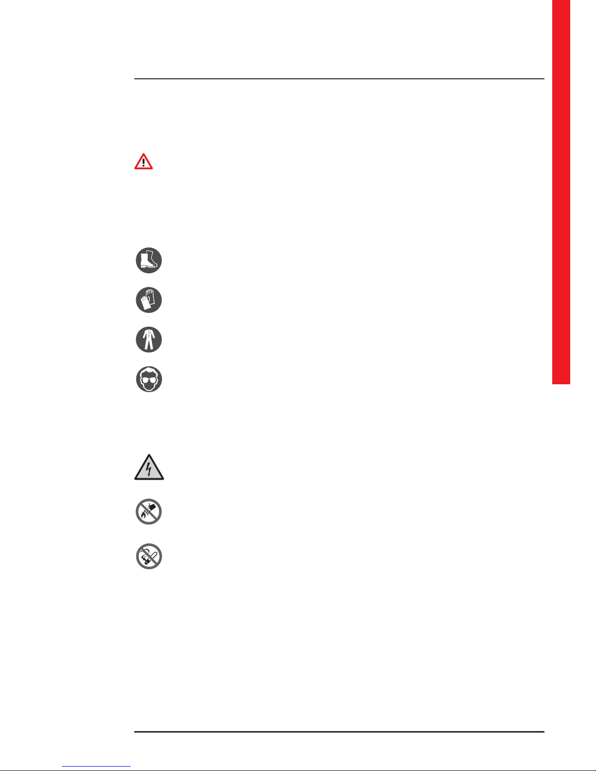
Electric current
It indicates the electrical live parts.
Emergency interventions
Do not use water to quench res but just the extinguishers specially designed for putting out res in electrical
equipments.
No smoking
It indicates that smoking is not allowed.
Page 10
10
2.5 Signs on the equipment
Displayed on the UPS are explanatory plates that can vary depending on the country the equipment is intended for and
constructional standards applied.
Make sure the instructions are adhered to. Removing these plates and working in a way that differs from what is written
there is strictly prohibited.
The plates must always be clearly read and they must be cleaned periodically.
If a plate deteriorates and/or it is no longer legible, even partially, the Manufacturer must be contacted for a replacement.
CAUTION
The plates must not be removed or covered. No other plates may be affixed to the equipment without the Manufacturer’s
prior written authorisation.
WARNING
Potential risks can be drastically reduced by wearing the Personal Protective Equipment listed in this chapter that are
considered indispensable. Always operate with due care around dangerous areas marked by the appropriate warning
notices on the equipment.
2.6 General warnings
DANGER
The UPS works with dangerous voltages. SKILLED TECHNICIANS shall perform the installation and ordinary
maintenance operations. No part of the UPS can be repaired by the operator.
Extraordinary maintenance operations must be carried out by LEGRAND Technical Support Service personnel.
DANGER
Before beginning any installation and/or maintenance operation, make sure that all the DC and AC power sources are
disconnected.
The UPS must be installed with an earth connection to avoid high leakage currents. First connect the earthing cable.
Check during each installation and/or maintenance operation the continuity of the earthing system.
DANGER
The UPS is powered by its own direct current energy source (batteries). The output terminals may have a dangerous
voltage even if the UPS is not connected to the power network in alternate current.
Disconnect all external battery units before performing any installation and/or maintenance operation.
2. Safety Regulations
Page 11

Archimod HE 240-480®
Installation and maintenance manual
11
WARNING
A battery can present a risk of electrical shock and high short circuit current. The following precautions should be
observed when working on batteries:
a) remove watches, rings or other metal objects.
b) use tools with insulated handles.
c) wear rubber gloves and boots.
d) do not lay tools or metal parts on top of batteries.
e) disconnect the charging source prior to connecting or disconnecting battery terminals.
f ) determine if battery is inadvertently grounded. If inadvertently grounded, remove source from ground. Contact with
any part of a grounded battery can result in electrical shock. The likelihood of such shock can be reduced if such
grounds are removed during installation and maintenance (applicable to equipment and remote battery supplies not
having a grounded supply circuit).
Do not dispose of batteries in a fire. The batteries may explode.
Do not open or mutilate batteries. Released electrolyte is harmful to the skin and eyes. It may be toxic. The batteries
installed inside the cabinet must be disposed of correctly. For the disposal requirements refer to local laws and relevant
standards.
CAUTION
The UPS functions with TT and TN systems. It has a pass-through neutral architecture: the status of the neutral on
output is the same as the neutral on input.
When the output load needs a different neutral status from the input status, it is necessary to place downstream of the
UPS a suitably scaled isolation transformer protected in compliance with the standards in force.
CAUTION
Do not open the battery fuse holders of the external battery units while the UPS is powering the loads in stored energy
mode.
WARNING
To reduce the risk of fire or electric shock, the UPS must work in closed, clean environments with controlled temperature
and humidity. It must be kept away from inflammable liquids and corrosive substances. The room temperature must not be
above +40°C (+104°F) and the relative humidity must be a maximum of 95% not condensing.
CAUTION
The equipment generates, uses and can radiate radio frequency energy, If it is not installed and used in accordance with
the instructions, it may cause harmful interference with radio communications.
Archimod HE 240-480 is a category C3 UPS according to the standard EN62040-2.
The UPS can be used in commercial and industrial environments; nevertheless restrictions or adequate countermeasures
might be necessary to avoid radio interference.
The qualified technician must also perform the following installation:
- Archimod HE 240: pass the input and output cable connections through two toroidal cores N30 material R 202 x 153 x
25 mm.
- Archimod HE 480: pass the input and output cable connections through four toroidal cores N30 material R 202 x 153 x
25 mm.
Page 12
12
CAUTION
- The equipment must be maintained and used according to the instructions of the manuals.
- The departmental manager must instruct the operating and maintenance personnel on the safe use and maintenance
of the equipment.
- Only specifically-trained, highly skilled personnel are allowed access to the equipment in order to perform maintenance.
While the maintenance operation is being carried out, signs saying “Maintenance work in progress” must be affixed in
the department in such a way that they can be easily seen from any access area.
- The connection of the equipment (and of any accessory devices) must always be perfectly grounded to discharge short-
circuit currents and electrostatic voltages. The input voltage must correspond with the value shown on the rating plate.
Current adapters must not be used under any circumstances. Pay attention to polarity when connecting.
- Any intervention on the equipment must be done only after it has been disconnected from the power supply network
by means of a switch disconnector and must be locked with an appropriate padlock.
- The UPS must not be turned on if liquid is leaking from the batteries.
- The equipment used for any maintenance operations (pliers, screwdrivers etc.) must be electrically insulated.
- Depositing flammable material near the equipment is strictly forbidden. The equipment should always be locked, and
only specifically trained personnel are allowed access to it.
- Do not disable any safety, notification or warning device and do not ignore any alarm, warning message or notice, no
matter whether they are generated automatically or represented by plates fixed to the equipment.
- Do not run the equipment with fixed protections not installed (panels etc.).
- In case of breaking, buckling or malfunctioning of the equipment or parts of it, repair or replace immediately.
- For no reason can the structure of the equipment, the devices mounted on it, the operation sequence etc, be modified,
manipulated or tampered with in any way, without prior consultation with the Manufacturer.
- Keep a register and enter therein the date, time, type, performer’s name and any other useful information about each
and any routine and extraordinary maintenance operation.
- Do not use oils or chemical products for cleaning because they could scratch, corrode or damage certain parts of the
equipment.
- The equipment and workplace must be kept completely clean.
- Upon completion of the maintenance operations, before connecting the power supply, carefully check that no tools
and/or material of any kind have been left next to the equipment.
CAUTION
The skilled technician must not leave at the disposal of the operator:
- the keys for opening the UPS door;
- the installation and maintenance manual.
2.7 How to proceed in an emergency
The following information are general.
For the specific interventions consult the regulations in force in the country where the equipment is installed.
2.7.1 First-aid procedures
When administering first aid, adhere to the company rules and the usual procedures.
2.7.2 Fire procedures
Do not use water to quench fires but just the extinguishers specially designed for putting out fires on electrical equipments.
2. Safety Regulations
Page 13
Archimod HE 240-480®
Installation and maintenance manual
13
3. Models
The UPSs Archimod HE 240-480 are sold without power modules. It is necessary to buy them separately.
The model 3 108 74 is the only one admitted for installation.
3.1 Archimod HE 240
(all dimensions are in mm)
Page 14

14
3. Models
Page 15
Archimod HE 240-480®
Installation and maintenance manual
15
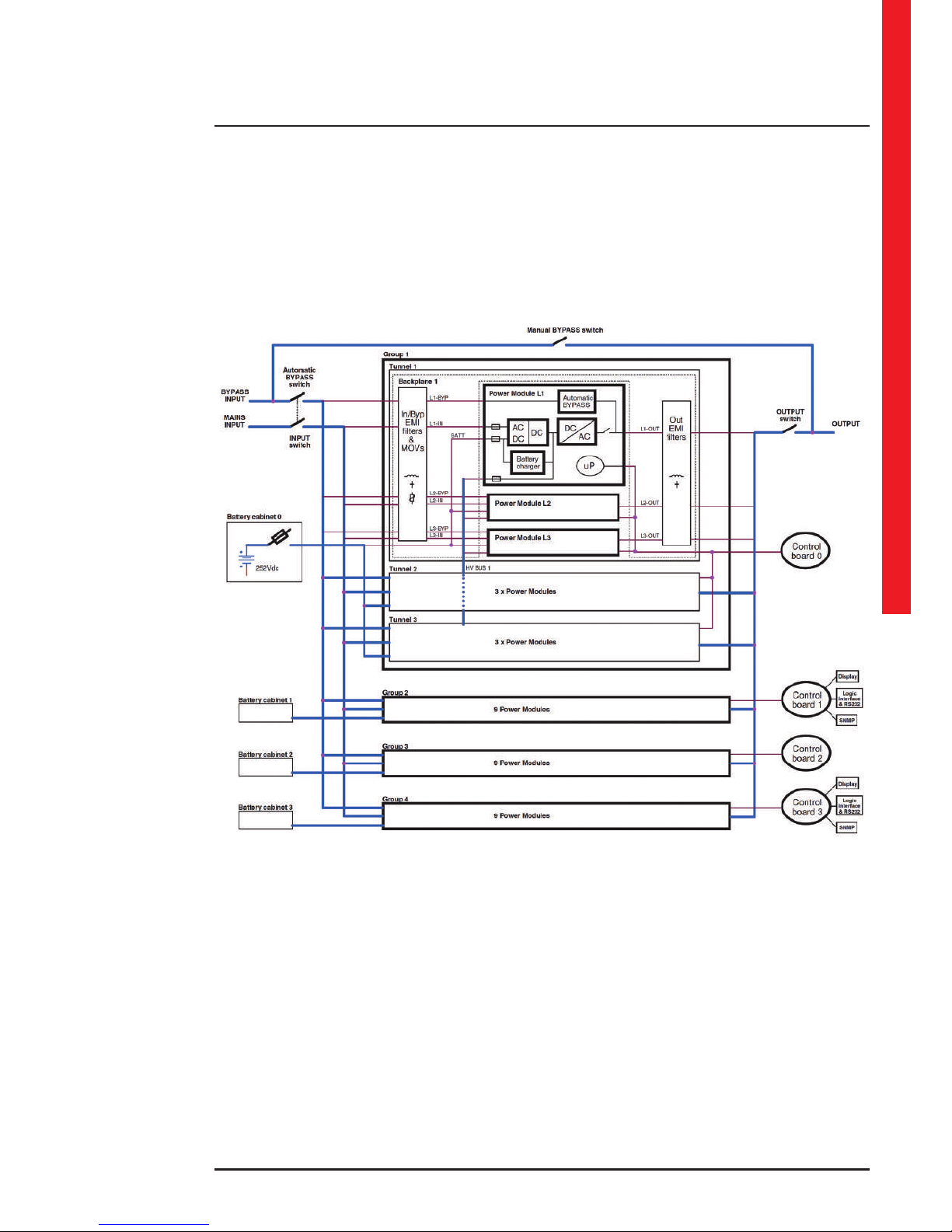
Block diagram
Page 16
16
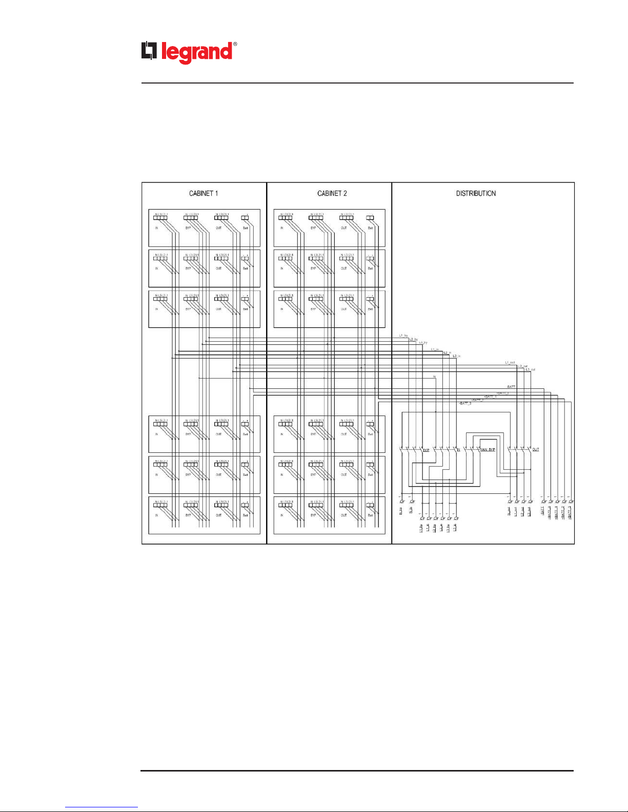
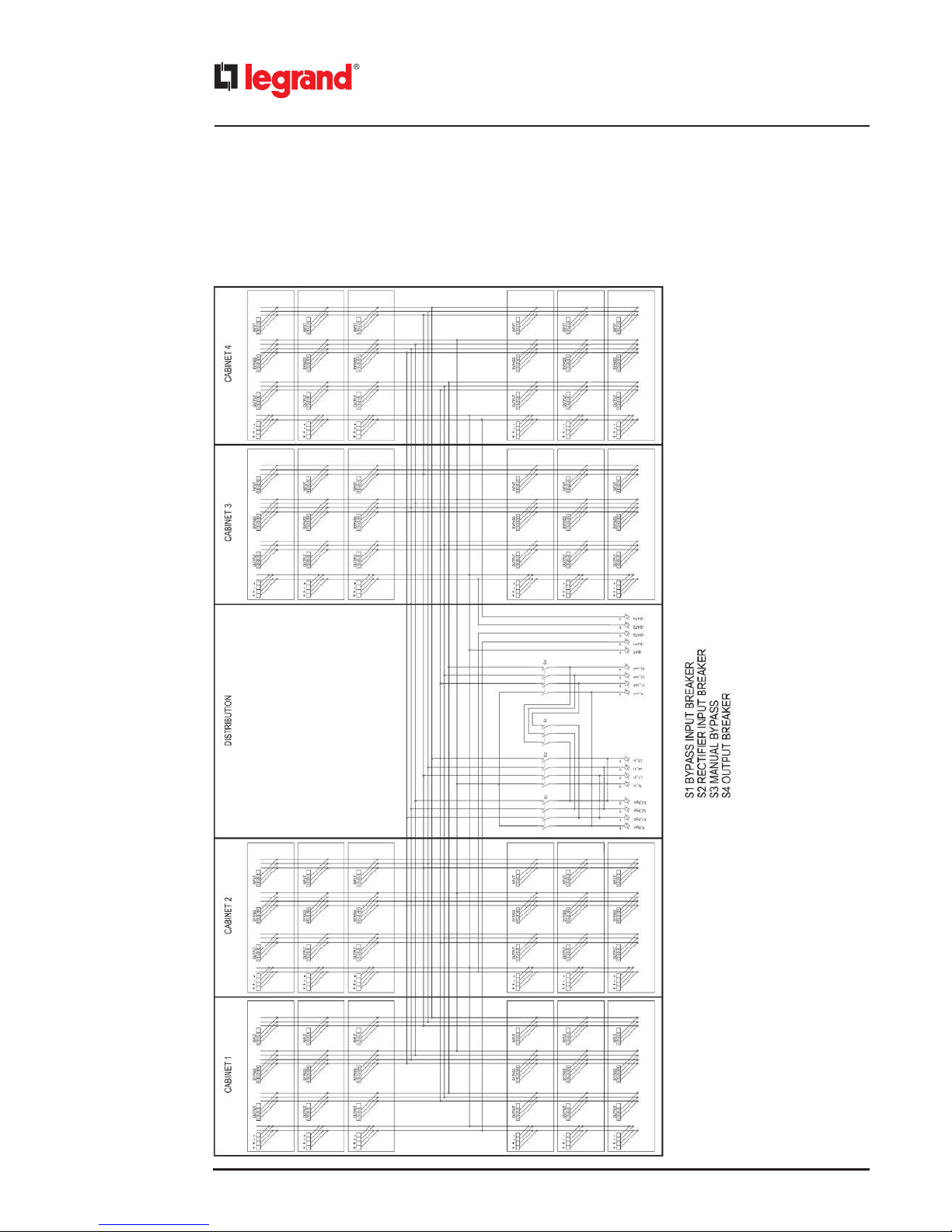
Block diagram of interconnections and distributions
The bypass input terminals are represented according to the factory configuration (bypass input line in common).
3. Models
Page 17
Archimod HE 240-480®
Installation and maintenance manual
17
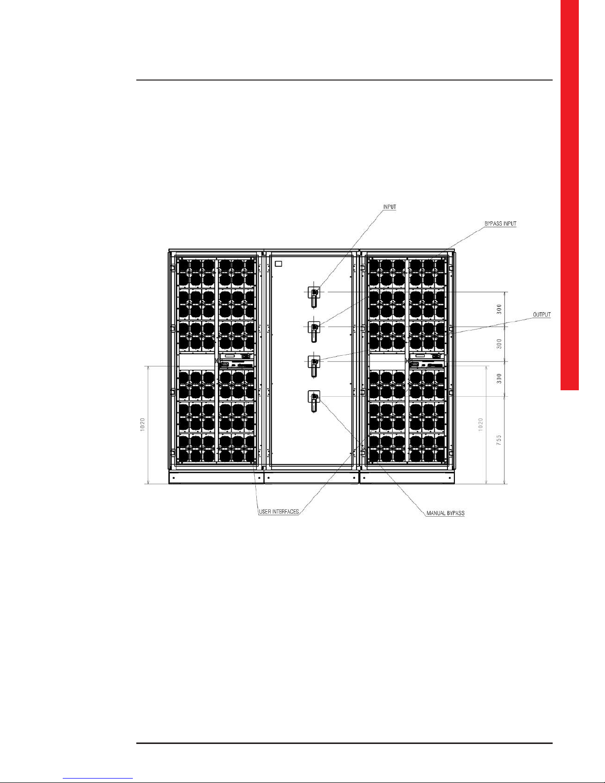
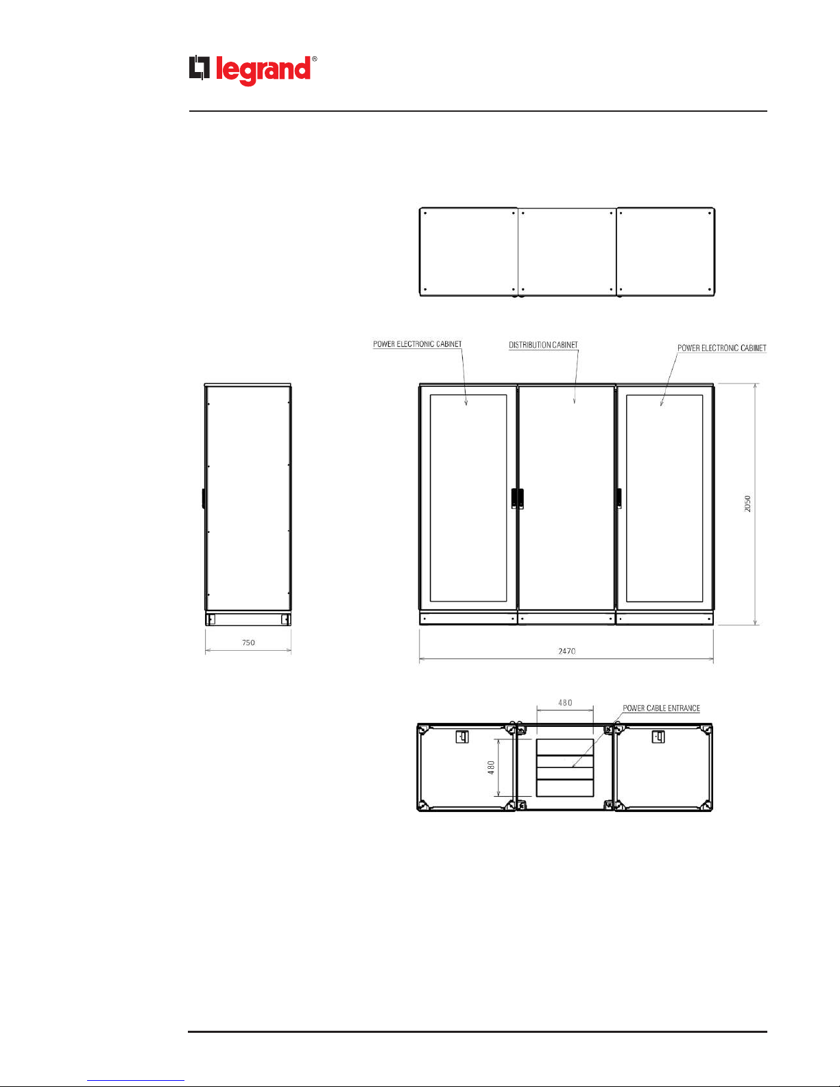
3.2 Archimod HE 480
(all dimensions are in mm)
Page 18
18
3. Models
Page 19
Archimod HE 240-480®
Installation and maintenance manual
19
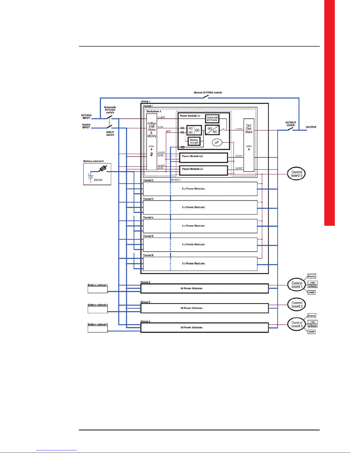
Block diagram
Page 20
20
Block diagram of interconnections and distributions
The bypass input terminals are represented according to the factory configuration (bypass input line in common).
3. Models
Page 21
Archimod HE 240-480®
Installation and maintenance manual
21
DANGER
The UPS installation operations must be carried out exclusively by a SKILLED TECHNICIAN (paragraph 2.2.1).
4.1 Safety regulations
CAUTION
Before carrying out any installation operation you must read and apply the following:
1. The UPS has a high leakage current. It is essential to make the earth connection before connecting the power supply.
It is necessary to make sure that the switchgear has a safe connection with the earth circuit and adequate protection
as required by the installation standards.
2. The UPS must only be installed in a xed way with a thermal-magnetic circuit breaker placed upstream of it. Connection
of the unit to the mains by means of a traditional plug is not allowed.
3. A protection circuit against voltage backfeed made as in the diagrams shown in paragraph 4.2.6 must be provided
outside the UPS.
4. The switchgear or the disconnector must be installed near the equipment and must be easily accessible.
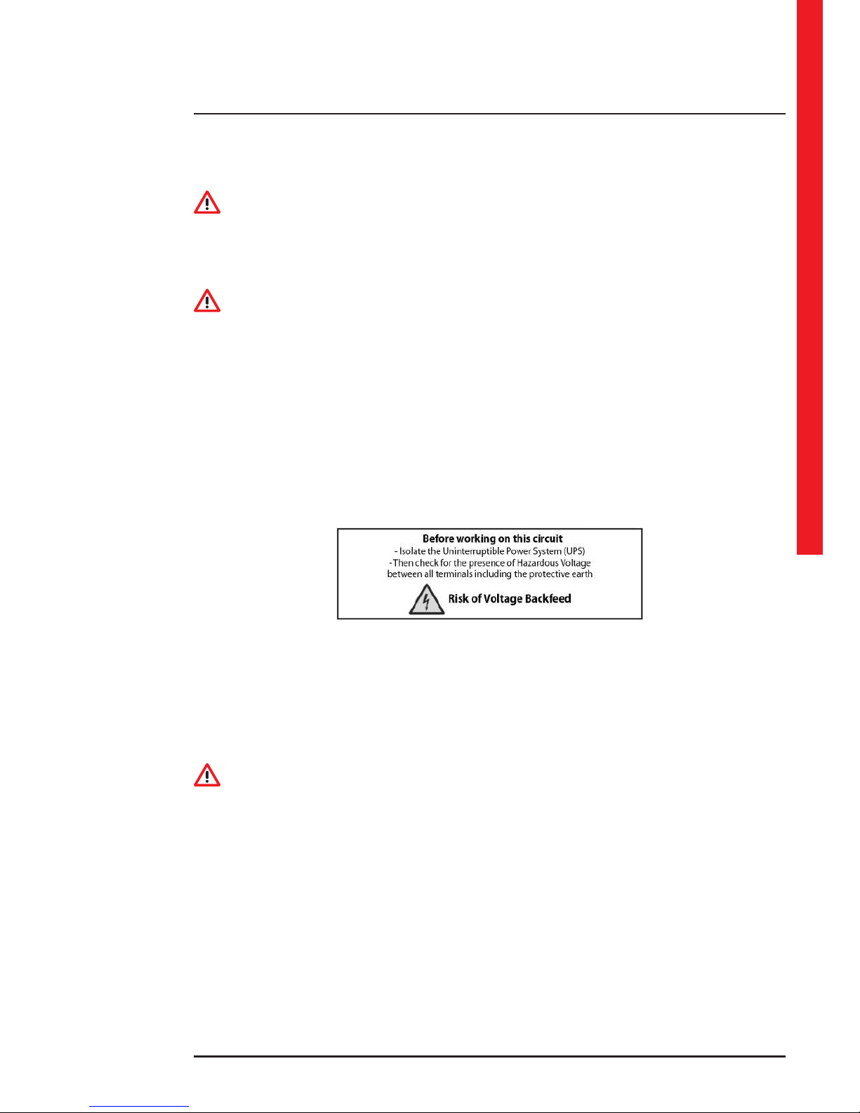
5. A warning label must be placed on all the mains disconnector switches installed away from the area of the UPS for the
purpose of reminding the assistance personnel of the fact that the circuit is connected to a UPS. The label must bear
the following text (or the equivalent):
4.2 Electrical connections
The electrical hook-up of the UPS to the switchgear is part of the installation that is not normally performed by the UPS
manufacturer; for this reason, the indications that follow are to be considered approximate and it is recommended that
the electrical connections are made on the basis of local installation standards.
After removing the UPS from the packaging and positioning it in its denitive place, the skilled technician can begin to
make the electrical connections.
CAUTION
The choice of cable type and their cross sections depending on the current they carry and their installations must be
made as indicated by the installation standards in force and it is a responsibility of the skilled technician.
The input current and the output power of the UPS are indicated in chapter 9 and the battery current in table 4 of chapter
10.
INDICATION
Chapter 10 shows the instructions for sizing cables, fuses and automatic and dierential switches.
4. Installation
Page 22

22
4.2.1 Safety warnings
DANGER
Before proceeding with the operations it is necessary to read and apply what is reported below. Proceeding with the
operations if one or more of the following conditions have not been met is prohibited.
• Do not carry out the installation if there is water or humidity around.
• Only open the UPS panels for the electrical connections. After making the connections, close and x all the panels.
• Check there is no mains voltage on the equipment.
• Check that the loads are o and disconnected from the UPS.
• Check the UPS is o and no voltage is present.
• Check that the battery disconnectors of the external battery units are open (OFF position).
4.2.2 Preliminary operations
Before connecting the UPS, check that:
• the mains input voltage and frequency correspond with the values indicated in the technical data on the UPS rating
plate;
• the earthing has been carried out in compliance with IEC (International Electrotechnical Commission) standards or local
regulations;
• the electrical system has been tted with the necessary residual-current and thermal-magnetic protections upline from
the UPS input.
4.2.3 Connection of the cabinets Archimod HE480
The following drawings indicate how to connect together the cabinets 3 104 76 and 3 104 77.
4. Installation
Page 23

Archimod HE 240-480®
Installation and maintenance manual
23
Page 24

24
4. Installation
Page 25

Archimod HE 240-480®
Installation and maintenance manual
25
Page 26

26
4. Installation
Page 27

Archimod HE 240-480®
Installation and maintenance manual
27
Page 28

28
4. Installation
Page 29

Archimod HE 240-480®
Installation and maintenance manual
29
4.2.4 Cabling
Archimod HE 240-480 has openings in the base for the passage of cables and fastening points for the cables themselves.
The cables must be tightly xed to the fastening points after they have been connected to the equipment.
Archimod HE 240
Archimod HE 480
Page 30

30
4.2.5 Earthing
Before carrying out any other installation operation, connect the earthing wire from the low voltage switchgear panel to
the earthing terminal on the base of the UPS cabinet where there are the connection busbars.
Archimod HE 240
Archimod HE 480
4.2.6 Protective devices
Adequate protection must be used at electrical system level to ensure the correct operation of the UPS and protect it
against overloads or output short circuits.
Install automatic dierential and thermal-magnetic circuit breakers upstream of the UPS on both the mains input line and the
bypass input line (if separate). The circuit breakers must be sized according to the indications of the tables in Chapter 10.
4.2.7 Backfeed protection
Archimod HE has integrated backfeed protection for TN systems and an auxiliary contact to activate the external circuit
by means of contactor for TT systems.
This auxiliary contact is available on the three-pole NO/C/NC terminal in the DIN rail in the cabinet where there are the
UPS connection busbars, as can be seen in the following picture:
4. Installation
Page 31

Archimod HE 240-480®
Installation and maintenance manual
31
If the UPS detects a voltage backfeed, the bypass input line disconnector switches o automatically and the backfeed
control contact changes status.
When the protection operates the cause must be checked.
To switch the UPS bypass input circuit disconnector on again reset it by turning it anticlockwise, then switch it on.
The auxiliary contact characteristics are:
• Maximum applicable voltage: 250Vac.
• Maximum applicable current: 5A, cosφ = 1
INDICATION
If during operation the UPS signals that the backfeed protection has been actuated, contact the LEGRAND Technical
Support Service.
TT distribution system and and backfeed protection circuit connection diagram with bypass line in common at
the mains input
S10: thermal-magnetic/dierential circuit isolation switch specied for the input line
S13: mains input line neutral opening contactor
S11: isolation switch in parallel to the S13 contactor coil
S12: two-pole isolation switch in series to the line to the EC9 connector of the relay interface card
Page 32

32
TT distribution system and and backfeed protection circuit connection diagram with a separate bypass line at the
mains input
S10-S14: thermal-magnetic/dierential isolation switches specied for the input line and the bypass line
S13: bypass line neutral opening contactor
S15: mains input line neutral opening contactor
S11: isolation switch in parallel to the S13 contactor coil
S12: two-pole isolation switch in series to the line to the EC9 connector of the relay interface card
INDICATION
By making the external backfeed protection as shown in the diagram, it is possible to isolate the line from the outside
and make it safe.
First switch on the S11 isolation switch in parallel to the contact coil and then switch o the S12 two-pole isolation switch
in series to the line to the EC9 connector.
4.2.8 External battery unit installation
Archimod HE 240-480 is set up to work both with strings of batteries in common or independent strings of batteries.
4. Installation
Page 33

Archimod HE 240-480®
Installation and maintenance manual
33
Archimod HE 240
Page 34

34
Archimod HE 480
The UPS negative pole battery busbars are in common and must always remain in this status.
The UPS positive pole battery busbars are connected in parallel by means of a plate. The factory connection has strings
of batteries in common.
To install independent strings of batteries remove the plate and make the conguration from the control panel to the end
of the UPS installation as described in the paragraph 5.5.
The positive pole battery busbars are marked as follows:
- +0: connected to the power modules controlled by the CM0 command board;
- +1: connected to the power modules controlled by the CM1 command board;
- +2: connected to the power modules controlled by the CM2 command board;
- +3: connected to the power modules controlled by the CM3 command board.
4. Installation
Page 35

Archimod HE 240-480®
Installation and maintenance manual
35
CAUTION
Table 4 of Chapter 10 gives the indications on the sizing of the cables to connect the UPS to the external battery units
according to the current output.
Supposing that there are n identical external battery units, each cable must bear the current indicated in the table divided
by n.
Use connection cables with the same cross section and similar lengths for the various external battery units.
INDICATION
Only batteries of the same type can be connected in parallel.
The connection must be made according to the passages indicated below:
1. Check that all the fuse-holder isolation switches of each external battery unit are o.
2. Loosen the screws that hold the UPS distribution panels and the external battery units closed.
3. Connect the UPS to the external battery units installed using the earthing cables (yellow-green).
4. Connect the positive and negative terminals of the UPS with those of the external battery units.
5. Close the external battery unit distribution panels. The UPS cabinet having the connection busbars can stay open to
make the next connections.
4.2.9 Mains connection
Before connecting the input power supply cables, make sure that all the UPS disconnectors are in the OFF position.
INDICATION
Chapter 10 gives indications on the sizing of the cables, fuses and automatic/dierential circuit breakers.
The default conguration is THREE PHASE INPUT and THREE PHASE 120° OUTPUT.
For dierent congurations, it is necessary to consult chapter 5.
Page 36

36
Archimod HE 240
4. Installation
Page 37

Archimod HE 240-480®
Installation and maintenance manual
37
Archimod HE 480
The connection must be made according to the passages indicated below:
- Before beginning to connect the mains, check that the available mains power is more than or the same as the nominal
UPS input power.
- Check that the cables to connect to the UPS are isolated upstream and no voltage is present.
- Check that the earthing cable from the low voltage switchgear panel is connected to the busbar xed on the UPS base.
- Connect the mains input neutral cable to the respective Nin mains busbar using a crimp terminal.
- Connect cables L1, L2 and L3 of the mains input line to the L1in, L2in and L3in busbars, using crimp terminals and being
careful to observe the phase sequence (L1, L2 and L3).
WARNING
The neutral input cable must ALWAYS be connected otherwise the UPS may be damaged irreparably once powered from
the mains.
Page 38

38
4.2.10 Bypass input line connection
The default conguration has the bypass line in common to the mains input.
Archimod HE 240
4. Installation
Page 39

Archimod HE 240-480®
Installation and maintenance manual
39
Archimod HE 480
A separate bypass line can only be connected if the bypass and mains input neutral conductors are in common (same
potential) and the two supply lines must always have a single dierential circuit breaker, if provided. The UPS has the
mains, bypass and output passing neutral and they are connected internally to each other.
INDICATION
Chapter 10 shows the instructions for sizing cables, fuses and automatic/residual current breakers.
The connection must be made according to the passages indicated below:
- Before beginning to connect the bypass line, check that the available mains power is more than or the same as the
nominal UPS input power.
- Check that the cables to connect to the UPS are isolated upstream and no voltage is present.
- Check that the bypass line earthing cable is connected to the busbar xed to the UPS base.
- Connect the bypass line neutral wire to the Nbyp busbar using a crimp terminal.
- Remove the three metal jumpers linking terminals L1in, L2in, L3in and L1byp, L2byp, L3byp.
- Connect the L1, L2 and L3 cables of the bypass input line to the L1byp, L2byp and L3byp busbars, using crimp terminals
and being careful to observe the phase sequence (L1, L2 and L3).
Page 40

40
WARNING
The separate bypass neutral cable must ALWAYS be connected, otherwise the UPS may be damaged irreparably once
powered from the mains.
4.2.11 Output line connection
Before beginning to connect the loads, check that the nominal power of the UPS indicated on the rating plate is more
than or the same as the total sum of the load powers.
The choice of the type and section of the connecting cables depending on their design current and installation must be
done as indicated in the current standards.
INDICATION
Chapter 10 shows the instructions for sizing the output cables.
Provide a separate switchgear for the load. It is advisable to use switches or automatic breakers in line with IEC standards
to protect the lines that originate from the switchgear.
Indicate the values reported below on the system switchgear by means of stickers or similar:
- maximum nominal power of the total load;
- maximum nominal power of the load at the load outlets;
- if a common switchgear is used (mains and UPS power outlets), make sure that there is an indication of the relative power
source on every power outlet (“Mains” or “UPS”).
The default conguration is THREE PHASE 120° OUTPUT.
For dierent congurations, it is necessary to consult chapter 5.
4. Installation
Page 41

Archimod HE 240-480®
Installation and maintenance manual
41
Archimod HE 240
Page 42

42
Archimod HE 480
The connection must be made according to the passages indicated below:
- Before beginning to connect the output, check that the UPS is o and that the output terminals are not live.
- Connect the output line earthing cables to the busbar xed to the UPS base using a crimp terminal.
- Connect the output line neutral cable to the Nout busbar using a crimp terminal.
- Connect the L1, L2 and L3 cables of the output line to the L1out, L2out and L3out busbars, using crimp terminals and
being careful to observe the phase sequence (L1, L2 and L3).
4. Installation
Page 43

Archimod HE 240-480®
Installation and maintenance manual
43
4.2.12 ARBC (Auxiliary Remote Bypass Contact)
The Archimod HE 240-480 makes it possible to enable forced bypass operation of the UPS without performing any
operation from the control panel but simply by means of a normally open external contact.
The external bypass contact terminal is found on the DIN rail at the top left in the UPS cabinet having the connection busbars.
For the correct connection of the external contact, the following requirements must be adhered to:
- use a double-insulation cable of up to 10 meters in length;
- make sure that the switch used is galvanically isolated.
The electric characteristics of the auxiliary remote bypass contact are the following:
- voltage with open contacts: less than 100 V
- current with closed contacts: less than100 mA
The gure below shows how the external bypass contact must be connected:
4.3 Insertion of power modules
Once all the electrical connections have been made, all the UPS panels can be screwed up again and the power modules
can be inserted in the UPS.
Insert the power modules one at a time checking that they abut. Fix them to the frame with the two screws provided with
each module , making sure that they are tightly xed. Use the SHC M4x20 screws (hex socket head). The two xing screws
also act as the module’s earth connection and must both be xed for safety purposes.
If one or more power modules is not installed, the free slots must be covered by putting the plastic cover of the kit
3 108 66 in each of them. The cover must be xed with two TCEI M4x20 screws.
Page 44

44
4.4 Communication devices
4.4.1 Description
The Archimod HE 240-480 UPS have two RS232 serial ports, a relay interface, an output at logic level on female DB15
connector and an SNMP slot for each of the control panels.
The communication interfaces can be found in the front part of the UPS which is only accessible to a skilled technician
who has the key to open the doors.
CAUTION
For the operator’s safety it is essential the interfaces are connected in such a way that:
- the maximum voltage between any two wires connected to the interface and between any one of these wires and the
earth is less than 42Vpk or less than 60Vdc;
- the isolation voltage between any wire connected to the interface and the earth is at least 1500Vac.
4. Installation
Page 45

Archimod HE 240-480®
Installation and maintenance manual
45
4.4.2 RS232 serial ports
The first of the two RS232 serial ports is called “maintenance RS232”. This port is dedicated exclusively to diagnostic functions
and to update the equipment firmware.
The second serial port is called “smart port (serial RS232)”. Through a computer this port makes it possible to access a set
of data relative to the functioning of the UPS as well as controlling the unmanned shutting down of the operating system.
The pinout of the RS232 interface is the following:
PIN FUNCTION
2 RX
3 TX
5 GND
1 - 4 - 6 connected together
7 - 8 connected together
Page 46

46
4.4.3 Relay interface
The notifications available through this interface are:
• battery mode functioning
• autonomy reserve
• generic alarm
• overload
• UPS in bypass mode
The contacts of the relay interface are programmed in default mode as normally open (NO) and with specific signalling
functions. These settings can however be changed by means of the control panel (see paragraph 6.4.2 - path UPS Setup
Dry contacts).
The contacts are available through 8 and 6 pole connectors.
The electric characteristics of the contact interface are the following:
- V
MAX
= 250 Vac / 30 Vdc.
- I
MAX
= 5 A.
The pinout is the following:
CONNECTOR A (8 poles)
PIN FUNCTION
1 - 2
Contact 1
default: battery mode functioning
3 - 4
Contact 2
default: autonomy reserve
5 - 6
Contact 3
Default: generic alarm
7 - 8
Contact 4
default: overload
CONNECTOR B (6 poles)
PIN
FUNCTION
1 - 2
Contact 5
default: UPS in bypass mode
3 - 4 EPO (see paragraph 4.4.4)
5 - 6 -
4. Installation
Page 47

Archimod HE 240-480®
Installation and maintenance manual
47
4.4.4 Emergency Power Off (EPO)
The UPS has an external normally closed contact (NC) that can be opened to activate the immediate stop of the equipment.
The EPO terminal is found on pins 3 and 4 of the 6-pole connector on the contact interface of each control panel.
The connection must be made as indicated below:
- connect the two EPO terminals of the control panels in parallel (connect pin 3 of the first terminal to pin 3 of the second
terminal and pin 4 of the first terminal to pin 4 of the second terminal);
- close the parallel on the normally closed (NC) external contact.
For the correct connection of the EPO, the following requirements must be adhered to:
- use a double-insulation cable of up to 10 meters in length;
- check that the switch used is galvanically isolated.
INDICATION
It is not possible to connect the EPO circuits of different UPSs in parallel. If necessary, use contacts on the EPO emergency
pushbutton isolated from each other.
The electric characteristics of the EPO interface are:
- voltage between terminals 3 and 4 with open circuit: 12Vdc.
- current between terminals 3 and 4 with closed circuit: 5mA.
The connection diagram is the following:
Page 48

48
4.4.5 Logic level interface
The logic level interface is available on connector DB15 and makes it possible to connect the UPS in remote control mode
with the aim of monitoring its functioning status. The following control signals are available:
• Mains/battery functioning
• Autonomy reserve
• UPS fault
• Overload
• UPS in bypass mode
• ON/OFF input
The electric characteristics of the logic level interface are:
- Logical output: V
MAX
= 12 Vdc , impedance on output: 2.2 kΩ in series
- Power supply: 12 Vdc , I
MAX
= 700 mA , not regulated.
- Open collector outputs: 30 Vdc , I
MAX
= 100 mA.
The pinout is the following:
PIN FUNCTION
1 GND
2 Mains / Battery (output, active high)
3
Autonomy reserve
(output, active high)
4 Power supply
7
Overload
(open collector, active low)
12
UPS in battery mode
(open collector, active low)
13
UPS in bypass mode
(open collector, active low)
14
Autonomy reserve
(open collector, active low)
15
Alarm
(open collector, active low)
5 - 6 - 8 - 9 - 10 - 11
do not connect
4. Installation
Page 49

Archimod HE 240-480®
Installation and maintenance manual
49
An example of open collector outputs is given below:
4.4.6 Network card (SNMP) slot
On each control panel there is a slot for the SNMP card (optional). By means of a network card it is possible to access to a
series of UPS operation data.
The current taken from the SNMP slot for the functioning of the network card must be in total less than 700mA.
Page 50

50
DANGER
All the congurations and start-up operations may only be done by a SKILLED TECHNICIAN (paragraph 2.2.1).
5.1 Introduction
This chapter contains all the information necessary for a correct conguration of the Archimod HE 240-480 HE UPS and
for its subsequent startup.
The factory conguration provides for THREE PHASE INPUT and 120° THREE PHASE OUTPUT.
5.2 Input configuration
The Archimod HE 240-480 automatically recognises the voltage, frequency and number of phases on input. No further
conguration by means of the control panel is therefore necessary.
CAUTION
Make sure the neutral wire is always connected.
5.3 Output configuration
During the start-up, select from the control panel the type of output voltage according to the applied load.
The default conguration for the Archimod HE 240-480 is 120° three phase 400 Vac.
Two dierent settings can be selected to manage the three phases:
- THREE PHASES 120°: this is the default setting and is usually used if three phase loads are applied on the UPS output
(e.g. three phase electrical motors) or if there are both three phase and single phase loads. The UPS manages the three
output phases protecting the three phase load. For example, if an excessive load is applied to one of the three output
lines, the automatic bypass switches all three lines on output.
- THREE SINGLE PHASE OUTPUTS: this setting is necessary if three single phase output lines with the neutral in common
have been created. The UPS manages the three outputs completely independently of each other. For example, if an
excessive load is applied to one of the three output lines, the bypass only cuts in on the overloaded line while the power
supply continues to be guaranteed on the other two by the UPS.
For the correct selection of the output conguration, follow the instructions given in paragraph 5.5.
5.4 Pre-start-up checks
Before powering the equipment, carry out the following checks:
1. Check that the mains input disconnector of the UPS is open (OFF position).
2. Check that the bypass input disconnector of the UPS is open (OFF position).
3. Check that the battery disconnectors of the external battery units are open.
4. Check that the maintenance bypass disconnector and the output disconnectors of the UPS are open (OFF position).
5. Check that the input and output wiring has been done and that all the connections have been tightened up properly.
6. Check the correct phase sequence of the mains input and bypass line (if separate).
7. Check that the parameters (voltage and frequency) of the mains input are compatible with those shown on the UPS
rating plate.
8. Check that all the power modules are inserted properly and that the xing screws of the power modules are present
and screwed up to abut the relative slots (use SHC M4x20 screws with hex socket head).
5. Conguration and Start-up
Page 51

Archimod HE 240-480®
Installation and maintenance manual
51
CAUTION
If fewer power modules are inserted than the maximum, protect the empty slots with the plastic covers of the kit 3 108 66.
Archimod HE 240
Page 52

52
Archimod HE 480
5.5 Start-up procedure
1. Insert the battery fuses into the appropriate fuse breakers of the external battery units.
2. Close the battery fuse breakers of the external battery units.
CAUTION
Before turning on the UPS it is necessary to select the right output conguration (Three Phases 120° / Three independent
phases). In order to do so, the rest of the procedure must be applied.
3. With the UPS o, press the ENTER key on the control panel and keep it held down until the text “Language” appears.
Using the ARROW UP and ARROW DOWN keys, select the language you require and conrm your choice with the ENTER
key.
4. Press the ESC key to leave the Language page. The text “Service Mode” appears on the display.
For further information about Service mode and how the control panel works, consult the user manual.
CAUTION
Archimod HE 240-480 is able to recognise the presence of non aligned rmware among the power modules and therefore
prevent the start-up. In Service Mode the status indicator ashes orange rapidly and the texts “Service Mode” and “PM FW
not updated!”
Follow the path Power Modules PM SW update to update the power module rmware (see paragraph 7.4.3). It is
possible to choose Update all PM to check and if necessary update all the power modules, while with the option Single
PM SW update you can select the specic power module to update.
5. Conguration and Start-up
Page 53

Archimod HE 240-480®
Installation and maintenance manual
53
5. Press the ENTER key to enter the menu. Using the ARROW UP and ARROW DOWN keys, it is possible to move the
selection on the display; the ENTER key is used to conrm the choice and the ESC key is used to cancel the choice.
Follow this path UPS Setup Output Inverter
Select “Three Phases 120°” or “Three Phases indep.” in accordance with the type of load and distribution downline of the
UPS.
CAUTION
Never select the “Single Phase” option because it is not supported.
CAUTION
Wrong connections or incorrect output congurations may cause injury and/or damage.
6. Follow the path UPS Setup Output Voltage and UPS Setup Output Frequency to check that the voltage
and the frequency set are the ones required.
CAUTION
Archimod HE 240-480 is congured as default with strings of batteries in common.
When installing with independent strings of batteries (separate for each command board), contact the LEGRAND Technical
Support Service to obtain the installer password and the conguration instructions.
The type of battery installation is congured following the path UPS Setup Batteries Common battery after
entering the password supplied by the LEGRAND Technical Support Service.
7. Follow the path UPS Setup Batteries Total KB to select the correct number of KB (Battery Kits) installed.
INDICATION
1 KB (Battery Kit) represents a string of 21 batteries in series.
Each external battery unit with a string of 21 batteries represents 1 KB.
When installing with independent strings of batteries, the KB value must be entered for each command board.
Example: if an Archimod HE 240 is connected to four external battery units in common, each containing 21 94Ah batteries,
a value of 4 KB must be set. If the four external battery units are independent, set the value of 1 KB for each of the
command board addresses.
8. Follow the path UPS Setup Batteries Capacity to select the correct value of the capacity in Ah of the individual
KB.
INDICATION
The UPS calculates the total battery capacity as produced by the total KB * Capacity.
When the conguration is with independent strings of batteries, the capacity value must be entered for each command
board.
Example: if an Archimod HE 240 is connected to four external battery units in common, each containing 21 94Ah batteries,
a value of 94Ah must be set. If the four external battery units are independent, set the value of 94Ah for each of the
command board addresses.
9. Leave the Service Mode pressing the ON/OFF key.
10. Provide the power supply to the UPS and close the UPS mains input disconnector and bypass input disconnector (ON
position).
INDICATION
If the “Standby Charge” function is enabled, when the UPS is powered a battery charge cycle is started automatically. Press
the ESC key to interrupt the standby charge and procede with the start-up procedure of the UPS Archimod HE 240-480
as described below.
11. Press the ON/OFF key to turn on the UPS. When the display shows the text “<ENTER> to conrm UPS turn ON”, press
the ENTER key.
CAUTION
If the rmware of the power modules is out of alignment, the status indicator ashes red rapidly and the display shows
the text “Invalid PM SW: to execute update”.
Page 54

54
Press the ENTER key to update the modules and complete the start up phase. Press the ESC key to interrupt the update
and start-up procedures.
If no operation is carried out within 30 seconds, the UPS turns o.
12. Wait for the backlit status indicator on the control panel to show a steady green light.
13. Check that the output voltage and frequency values set correspond with the requirements of the applied load. If this
is not the case, insert the values necessary (see the user manual).
14. Close the output disconnector (position ON) of the UPS. At this point, the load is powered by the UPS.
15. Close the UPS doors and remove the key.
INDICATION
If during the installation phase it is necessary to check the proper functioning of the UPS in stored energy mode, remove
the mains by means of the breaker placed upstream of the UPS.
CAUTION
Do not remove the power modules during the functioning of the UPS without rst having activate the proper hot-swap
procedure (described in paragraph 6.4). The removal of one or more power modules without the proper use of the hotswap procedure could damage the equipment.
CAUTION
The keys for opening the UPS doors must not be left at the operator’s disposal.
WARNING
The installation and maintenance manual must not be left at the disposal of the operator.
5.6 ECO MODE setup
The Archimod HE 240-480 has a functioning mode called “eco mode”, in which the load is supplied directly from the
electrical mains through the automatic bypass circuit inside the power modules.
If the output voltage leaves the window of tolerance (-20% / +15% of the voltage set on output), the UPS actuates its
inverter stage and supplies the load with energy stored in the batteries.
When the input mains are back within the tolerance values, the UPS is automatically taken back to the eco mode. It is
possible to change the functioning mode between on-line and o-line mode (and vice versa) both with UPS on and with
the UPS o (through the “Service Mode” function menu).
To activate the eco mode, enter the main menu and follow the path UPS Setup Bypass O-line Mode. Select
“Enabled” and press the ENTER key to conrm the choice.
To return to the on-line mode, enter the main menu and follow the path UPS Setup Bypass O-line Mode. Select
“Disabled” and press the ENTER key to conrm the choice.
INDICATION
If the load needs to be supplied with a voltage without disturbances or with a voltage regulated in amplitude and/or
frequency it is necessary to use the UPS in double conversion on-line mode.
5.7 EMERGENCY POWER SYSTEM (EPS) MODE setup
The Archimod HE 240-480 has an “emergency power system” functioning mode that is useful for example to power an
emergency lighting system.
When there is input from the mains, the UPS output is disabled. If the mains input is missing, the output is supplied by
the UPS functioning with batteries.
It is possible to enable or disable the EPS function only in Service Mode (with the UPS o ).
The path to follow is UPS Setup Options EPS mode. Select “Enabled” of “Disabled” and press the ENTER key to
conrm the choice.
5. Conguration and Start-up
Page 55

Archimod HE 240-480®
Installation and maintenance manual
55
6. Maintenance
DANGER
The ORDINARY MAINTENANCE operations may only be done by SKILLED TECHNICIANS (paragraph 2.2.1). The
EXTRAORDINARY MAINTENANCE operations may only be done by the LEGRAND TECHNICAL SUPPORT SERVICE.
6.1 Introduction
This chapter contains all the information necessary to a skilled technician for a correct maintenance of the Archimod HE
240-480 UPS.
DANGER
The operator is not authorised to perform the operations contained in this chapter.
LEGRAND declines all liability for any injury or damage caused by activities carried out dierently from the instructions
in this manual or by a skilled technician who does not observe the requirements laid down in the installation and
maintenance manual.
6.2 Preventive maintenance
The UPS does not contain parts for preventative maintenance by the operator.
The operator must regularly perform:
- a general external cleaning;
- the check of the lack of alarms on the display;
- the check that the ventilating fans on each power module are working correctly.
During a preventive maintenance inspection the skilled technician must carry out the following checks:
- no alarm presence;
- list of the memorised events;
- correct function of the static and maintenance bypass;
- integrity of the electrical installation;
- ow of cold air;
- battery status;
- characteristics of the applied load;
- conditions of the installation location.
After the rst year of UPS life, check the batteries every six months through the “battery calibration” function to guarantee
the optimal operation and continuous protection of the connected load. With this function, the UPS detects the discharge
curve of the batteries.
To activate the operation, enter the main menu and follow the path Tools Batteries Batt. Calibration.
Press the ENTER key to conrm the choice.
Contact the LEGRAND Technical Support Service in case of problems.
6.3 Periodical checks
The correct functioning of the UPS must be guaranteed by periodical maintenance inspections. These are essential to
safeguard the reliability of the UPS.
DANGER
The periodical checks involve operations inside the UPS where there are dangerous voltages. Only people who are trained
by LEGRAND are authorized to work.
Page 56

56
6.4 Ordinary maintenance
6.4.1 Power module hot-swap replacement or inclusion of new modules
Archimod HE 240-480 allows the hot-swap replacement of the power modules if they fail or if new modules are inserted.
The load is always protected by the UPS without being supplied by the bypass line.
The procedure requires the turning o of the modules that are managed by the same command board. The load is
powered by the remaining power modules.
INDICATION
To use the hot-swap function, it is necessary to have sized the UPS properly. If the percentage of the load does not allow
the hot-swap without overload, perform the manual bypass mode maintenance procedure.
The command boards (CM) and the power modules (PM) are identied by a unique address inside the system, as shown
below:
Archimod HE 240
CM 0
PM 0 PM 1 PM 2
PM 3 PM 4 PM 5
PM 6 PM 7 PM 8
control panel
PM 9 PM 10 PM 11
PM 12 PM 13 PM 14
PM 15 PM 16 PM 17
CM 1
CM 2
PM 18 PM 19 PM 20
PM 21 PM 22 PM 23
PM 24 PM 25 PM 26
control panel
PM 27 PM 28 PM 29
PM 30 PM 31 PM 32
PM 33 PM 34 PM 35
CM 3
6. Maintenance
Page 57

Archimod HE 240-480®
Installation and maintenance manual
57
Archimod HE 480
CM 0 CM 1
PM 0 PM 1 PM 2 PM 18 PM 19 PM 20
PM 3 PM 4 PM 5 PM 21 PM 22 PM 23
PM 6 PM 7 PM 8 PM 24 PM 25 PM 26
control panel
PM 9 PM 10 PM 11 PM 27 PM 28 PM 29
PM 12 PM 13 PM 14 PM 30 PM 31 PM 32
PM 15 PM 16 PM 17 PM 33 PM 34 PM 35
CM 2 CM 3
PM 36 PM 37 PM 38 PM 54 PM 55 PM 56
PM 39 PM 40 PM 41 PM 57 PM 58 PM 59
PM 42 PM 43 PM 44 PM 60 PM 61 PM 62
control panel
PM 45 PM 46 PM 47 PM 63 PM 64 PM 65
PM 48 PM 49 PM 50 PM 66 PM 67 PM 68
PM 51 PM 52 PM 53 PM 69 PM 70 PM 71
In the Archimod HE 240 UPS there are four command boards. Each of them controls nine power modules.
In the Archimod HE 480 UPS there are four command boards. Each of them controls eighteen power modules.
To change or add a power module, all modules belonging to one command board are switched o. The maximum power
available becomes 75% of the nominal power for both UPS models.
Do the following to replace one or more faulty modules:
1. Check that the load percentage applied to the UPS allows the hot-swap replacement without overloading the UPS.
2. Open the doors of the UPS and identify the command board that controls the power module you want to replace.
3. Press the ON/OFF key briey (less than 0.5 seconds).
Page 58

58
INDICATION
A continuous pressing of the ON/OFF key for more than 2 seconds brings up the question “Turn o the UPS?” on the
display. If this occurs, press the ESC key.
4. Press the ENTER key to access the Hot swap submenu. Using the ARROW UP/DOWN keys, choose the command board
(CM) on which to perform the hot-swap. The group of associated power modules that are turned o are identied by
the fast ashing of the front LED in red.
5. Press the ENTER key. The command board selected turns o all the associated power modules and stays in standby
mode.
6. Await the complete shutdown of the power modules (front LED o and fans still).
7. Undo the xing screws of the power modules that you intend to replace and conserve them.
8. Take the power modules you intend to replace out one at a time.
9. Check that the two LEDs visible through the two holes in the side cover are o on all the new power modules. If they
are on, wait till they turn o.
10. Insert the new modules one at a time making sure that they are in abutment and x them using the screws removed
previously. The two xing screws allow the module’s earthing and must both be xed for safety purposes.
11. Press the ON/OFF key briey (less than 0.5 seconds).
INDICATION
A continuous pressing of the ON/OFF key for more than 2 seconds brings up the question “Turn o the UPS?” on the
display. If this occurs, press the ESC key.
12. Press the ENTER key to access the Hot swap submenu. Using the ARROW UP/DOWN keys, choose the command board
(CM) indicated as being OFF and press the ENTER key. The command board automatically restarts all the associated
power modules.
13. The progress bar (“CM initialize”) makes it possible to monitor the completion of the operation. At the end of the
operations, the UPS returns to operate with all the power modules.
14. Close the UPS doors (the keys must not be left at the operator’s disposal).
INDICATION
The procedure to add power modules is similar to the previous one. At point 7 remove the plastic covers of the kit
3 108 66 which protect the empty slots where new power modules are to be added.
CAUTION
Archimod HE 240-480 is able to recognise the presence of non aligned rmware among the power modules and therefore
prevent the start-up.
If the rmware of the power modules is out of alignment, the status indicator ashes red rapidly and the display shows
the text “Invalid PM SW Versions: to execute update”.
Press the ENTER key to update the power modules and complete the exit from the hot-swap mode.
Press the ESC key or do not carry out any operation for thirty seconds to interrupt the exit procedure from the hot-swap
mode. In this case the “Modules turned OFF” and “PM FW not updated!” texts alternate on the display and the status
indicator ashes intermittent orange. To update the power modules, go into the Hot swap submenu and turn on the
command board that is o.
INDICATION
If one or more screws are lost, only use M4x20 SHC screws (socket hex head screws) to x the power modules.
WARNING
Do not touch the backplane of the tunnel left uncovered for the removal of the power modules because there are
dangerous live parts.
On the cover of the power module there are two holes from which it is possible to see two LEDs that signal the presence of
dangerous voltage on the rear connection. Before performing any operation on the power module, make sure that these
LEDs are o. If they are on, wait for them to turn o.
If one or more power modules are not installed, the free slots must be protected by using the plastic cover of the kit 3 108
66 in each of them. The cover must be xed with two SHC M4X20 screws.
6. Maintenance
Page 59

Archimod HE 240-480®
Installation and maintenance manual
59
6.4.2 Maintenance procedure for the UPS in maintenance bypass mode
If the power module hot-swap replacement procedure (paragraph 6.4.1) is not applicable, the replacement or the addition
can be made with the UPS in maintenance bypass mode.
This mode is also necessary to perform maintenance or replace parts such as command boards, backplanes, update the
UPS rmware, etc.
CAUTION
During forced and maintenance bypass operations, the load is not protected because it is supplied from the bypass input
line.
CAUTION
The power modules must not be replaced in this mode without adhering scrupulously to the instructions below.
Accessing the manual maintenance bypass mode
1. Open the Archimod HE 240-480 UPS doors.
2. Enable the UPS in forced bypass mode. Enter the main menu and follow the path UPS Setup Bypass Forced
Mode.
Set the value of the parameter to “Enable” with the ARROW UP/DOWN keys. Press the ENTER key to conrm.
In this condition the power modules are excluded and the load is powered directly from the mains. The display shows
the text “Forced on Bypass”. When the equipment is in forced bypass mode, the status indicator ashes quickly. The
LEDs on the power modules ash quickly as well.
3. Close the maintenance manual bypass disconnector by bringing it to the ON position. The load is powered directly from
the mains. The display shows the text “Maintenance Bypass”.
4. Open the output disconnector bringing it to the OFF position.
5. Shutdown the UPS by holding the ON/OFF key down for a few seconds. When the display shows the text “Turn o the
UPS?”, press the ENTER key.
6. Open the mains input disconnector and bypass input disconnector by bringing them to the OFF position.
7. Open the battery disconnectors of all the external battery units.
8. Press the ON/OFF key to discharge any internal capacity. It is now possible to proceed with the maintenance operations.
WARNING
Inside the drawer where the command cards and the relay interface card are located there could be dangerous voltage
due to the connection of the external backfeed control line.
Be careful of connector EC9 of the relay interface card to which the backfeed line is connected.
Note: by making the external backfeed protection as per the diagram in paragraph 4.2.6, it is possible to isolate the line
from the outside and make it safe.
Page 60

60
Power module replacement or inclusion of new modules
1. Check that the procedure for placing in maintenance bypass mode described above has been applied.
2. Extract the power module after undoing the two xing screws.
CAUTION
On the cover of the power module there are two holes from which it is possible to see two LEDs that signal the presence of
dangerous voltage on the rear connection. Before performing any operation on the power module, make sure that these
LEDs are o. If they are on, wait for them to turn o.
3. Check that the two LEDs visible through the two holes in the side cover of the new power module are o. If they are on,
wait for them to turn o.
4. Insert the new power module in the same slot where the previous one was located.
5. Fix the new power module to the UPS frame with the two screws provided along with the power module, making sure
they abut. Use SHC M4x20 screws (hex socket head). The two xing screws allow the module’s earthing and must both
be xed for safety purposes.
The procedure described does not need further manual settings from the control panel. The UPS automatically recognises
the new power module and it is congured automatically.
INDICATION
The procedure to add power modules is similar to the previous one. At point 2 remove the plastic covers of kit 3 108 66
which protect the empty slots where new power modules are to be added.
Exit from maintenance manual bypass mode
To transfer the UPS from the maintenance bypass mode to the online mode, do the following:
1. Check that the output disconnector is open (OFF position).
2. Close all battery disconnectors of the external battery units.
3. Close the mains input disconnector and bypass input disconnector by bringing them to the ON position.
4. Press the ON/OFF key to turn on the UPS. When the display shows the text “<ENTER> to conrm UPS turn ON”, press
the ENTER key.
CAUTION
Archimod HE 240-480 is able to recognise the presence of non aligned rmware among the power modules and therefore
prevent the start-up.
If the rmware of the power modules is out of alignment, the status indicator ashes red rapidly and the display shows
the text “Invalid PM SW Versions: to execute update”.
Press the ENTER key to update the power modules and complete the start up phase of the UPS.
Press the ESC key to interrupt the update and start-up procedures.
If no operation is carried out within 30 seconds, the UPS turns o.
5. Wait for the power-on procedure to be completed. The main screen is shown on the display. In this condition the
load is supplied directly by the bypass line. The display shows the text “Manual Bypass” and “Forced on Bypass”.
The backlit status indicator becomes orange.
6. Open the output disconnector by bringing it to the ON position.
7. Open the maintenance manual bypass disconnector by bringing it to the OFF position.
8. Enable the UPS in inverter (on-line) mode. Enter the main menu and follow the path UPS Setup Bypass Forced
Mode.
Set the value of the parameter to “Disabled” with the ARROW UP/DOWN keys. Press the ENTER key to conrm.
9. At the end of the procedure the load is powered by the UPS. Under these conditions the backlit indicator shines green.
10. Close the UPS doors (the keys must not be left at the operator’s disposal).
6. Maintenance
Page 61

Archimod HE 240-480®
Installation and maintenance manual
61
6.4.3 Maintenance procedure with UPS off
CAUTION
The shutdown procedure must be applied only if the load is o or does not need to be powered by the UPS.
1. Keep the ON/OFF key pressed for at least two seconds.
2. When the display shows the text “Turn o the UPS?”, press the ENTER key.
3. Wait for the shutdown operations to complete.
4. Open the output disconnector by bringing it to the OFF position.
5. Open the mains input disconnector and bypass input disconnector by bringing them to the OFF position.
6. Open the battery disconnectors of the external battery units.
7. Press the ON/OFF key to discharge any internal capacity.
8. Open the circuit breaker upstream of the UPS which supplies power from the mains. If these operations are performed
correctly, there will be no voltage to the UPS. It is now possible to proceed with the maintenance operations.
WARNING
Inside the drawer where the command boards and the relay interface card are located there could be dangerous voltage
due to the connection of the external backfeed control line.
Be careful of connector EC9 of the relay interface card to which the backfeed line is connected.
Note: by making the external backfeed protection as per the diagram in paragraph 4.2.6, it is possible to isolate the line
from outside and make it safe.
6.5 Replacing the fuses and surge arrester (DIN rail)
A surge arrester and two fuse holders can be found in the DIN rail inside the cabinet with the UPS connection busbars.
The rst fuse holder, containing a 16 A fuse, is in series to the surge arrester. The second fuse holder, containing a 2 A fuse,
is in series to the input bypass disconnector release coil.
Page 62

62
If necessary replace the fuses and the surge arrester as indicated in the following picture:
6.6 Requirements for external battery units
When performing maintenance on the external battery units with the UPS in normal mode the latter must be placed in
manual maintenance bypass mode.
CAUTION
During operation in manual maintenance bypass mode, the load is not protected because it is supplied by the bypass
input line.
INDICATION
If the installation/removal procedure changes the total number of KB installed, it is necessary to update this setting from
the control panel.
After concluding the installation/replacement operations, calibrate the batteries from the control panel to get precise
indications regarding the total autonomy of the UPS. To activate the function, enter the main menu and follow the path
Tools Batteries Batt. Calibration.
Press the ENTER key to conrm the choice.
6.7 Extraordinary maintenance
Contact the LEGRAND Technical Support Service if faults have occurred which require access to internal parts of the UPS.
6. Maintenance
Page 63

Archimod HE 240-480®
Installation and maintenance manual
63
7. Warehousing
DANGER
All storage operations may only be done by a SKILLED TECHNICIAN (paragraph 2.2.1).
DANGER
A SKILLED TECHNICIAN must check that there is no voltage present before disconnecting the cables. All the
battery isolator switches on the external battery units must be open.
7.1 UPS
The UPS must be stored in an environment with a room temperature between -20°C (-4°F) and +50°C (+122°F) and humidity
less than 90% (not condensing).
7.2 Batteries
It is possible to store VRLA batteries without recharging them in the following conditions:
- up to 6 months at +20°C (+68°F);
- up to 3 months at +30°C (+86°F);
- up to 2 months at +35°C (+95°F).
Contact a skilled technician if the batteries must be recharged.
CAUTION
The external battery units must never be stored if the batteries are partially or totally discharged.
LEGRAND is not liable for any damage or bad functioning caused to the UPS by wrong warehousing.
Page 64

64
8. Dismantling
DANGER
Dismantling and disposal operations may only be done by a SKILLED TECHNICIAN (paragraph 2.2.1)
The instructions in this chapter are to be considered indicative: in every country there are dierent regulations with
regard to the disposal of electronic or hazardous waste such as batteries. It is necessary to strictly adhere to the
standards in force in the country where the equipment is used.
Do not throw any component of the equipment in the ordinary rubbish.
8.1 Batteries disposal
Batteries must be disposed of in a site intended for the recovery of toxic waste. Disposal in the traditional rubbish is not
allowed.
Apply to the competent agencies in your countries for the proper procedure.
Pb
WARNING
A battery may constitute a risk of an electric shock and high short-circuit current.
When working on batteries, the prescriptions indicated in chapter 2 must be adhered to.
8.2 UPS dismantling
The dismantling of the UPS must occur after the dismantling of the various parts it consists of.
For the dismantling operations, it is necessary to wear the Personal Protective Equipment mentioned in paragraph 2.3
and to consult the instructions and diagrams in the installation and maintenance manual.
Sub-divide the components separating the metal from the plastic, from the copper and so on according to the type of
selective waste disposal in the country where the machine is dismantled.
If the dismantled components must be stored waiting to be taken to the dump, be careful to keep them in a safe place
protected from atmospheric agents to avoid soil and groundwater contamination.
8.3 Electronic component dismantling
For the disposal of electronic waste like the control panel or the command boards it is necessary to refer to the relevant
standards.
Page 65

Archimod HE 240-480®
Installation and maintenance manual
65
MAIN FEATURES
3 104 75 3 104 76 + 3 104 77
Nominal power 240 kVA 480 kVA
Active Power 240 kW 480 kW
Technology
online, double conversion
Classication according to EN62040-3: VFI-SS-111
IN/OUT Conguration Three-phase / Three-phase
Neutral system Passing system
Dual Input Available on all the models
Power columns 2 4
Command boards 4
UPS architecture
Modular with power modules PM7 3 108 73 of 6,700 VA (PF=1)
Expandable, redundant N+X
Waveform in
normal mode
Pure sine
Waveform in stored
energy mode
Pure sine
Bypass
Automatic (static and electromechanical)
Manual (for maintenance)
Transfer time 0 ms
INPUT ELECTRICAL CHARACTERISTICS
3 104 75 3 104 76 + 3 104 77
Maximum input current
(with minimum input
voltage and battery
charger active)
462 A 924 A
Nominal input voltage
400 V + 15% - 20% (Three-phase)
(neutral line indispensable)
Input frequency
50 / 60 Hz ± 5 Hz
autosensing
Power factor on input PF > 0.99
Total harmonic distortion
of the input current
THDi < 3%
9. Technical data
Page 66

66
ELECTRICAL OUTPUT CHARACTERISTICS (NORMAL MODE)
3 104 75 3 104 76 + 3 104 77
Maximum output current 347 A 694 A
Nominal output voltage 400 V ± 1% (Three-phase)
Nominal output frequency
50 / 60 Hz
(autosensing and/or selectable by the user)
Tolerance on the
output frequency
synchronised to the bypass line with range from ± 0.5 Hz to ± 7 Hz
adjustable from the control panel
Crest factor admitted on
the output current
3:1
Total harmonic distortion
of output voltage on
linear nominal load
< 0.5%
Total harmonic distortion
of output voltage on non-
linear nominal load
< 1%
Eciency in Normal Mode up to 96%
Eciency in Eco Mode 99% max
Overload admitted
115% for 10 minutes without automatic bypass intervention
135% for 60 seconds without automatic bypass intervention
ELECTRICAL OUTPUT CHARACTERISTICS (STORED ENERGY MODE)
3 104 75 3 104 76 + 3 104 77
Nominal output voltage 400 V ± 1% (Three-phase)
Output frequency 50 / 60 Hz ± 1%
Total harmonic distortion
of output voltage on
linear nominal load
< 0.5%
Total harmonic distortion
of output voltage on
non-linear nominal load
< 1%
Overload admitted
115% for 2 minutes
135% for 30 seconds
9. Technical data
Page 67

Archimod HE 240-480®
Installation and maintenance manual
67
BATTERIES AND BATTERY CHARGER CHARACTERISTICS
3 104 75 3 104 76 + 3 104 77
Nominal battery
voltage UPS
252 Vdc (21 x 12 Vdc batteries in series)
External battery unit
Type of battery charger High performance PWM, one for each power module
Recharge curve Smart Charge, advanced three-stage cycle
Nominal recharge current
battery charger
2.5 A max for every power module installed
FEATURES
3 104 75 3 104 76 + 3 104 77
Signals and alarms
Large four line alphanumeric screen, multicolour status indicator,
acoustic notication
Communications ports two RS 232 ports, two relay interfaces, two contact ports, two SMNP module slots
Software
Free software for Windows and Linux environments is available to
implement the following functions:
- displaying all the functioning and diagnostic data in case of problems;
- setup of special functions;
- automatic shutdown of all the computers supplied by the UPS
(if connected to TCP/IP network).
Visit us at http://www.ups.legrand.com to download a copy of the software free of
charge.
Protections
Electronics against overloads, short-circuit and excessive battery discharge
Block of functions due to the end of autonomy
In-rush limiter on start up
E.P.O. contact
Auxiliary contact for backfeed protection
MECHANICAL CHARACTERISTICS
3 104 75 3 104 76 + 3 104 77
Net weight
(empty cabinet)
440 kg 256 kg + 610 kg
Dimensions (mm)
(w x h x d)
1,350 x 2,050 x 750 820 x 2,050 x 750 + 1,650 x 2,050 x 750
Power modules 6,700VA
(PM7) 3 108 73 installable
up to 36 up to 72
Net power module weight 8.5 kg
Page 68

68
ENVIRONMENTAL CONDITIONS
3 104 75 3 104 76 + 3 104 77
Operating temperature 0 °C ÷ 40 °C
Relative humidity
during operation
0% ÷ 95% non condensing
Storage temperature -20 °C ÷ 50 °C (excluding batteries)
Noise level at 1 metre < 80 dBA
IP code IP 21
Operating height up to 1000 metres above sea level without derating
Heat dissipation with
full load
43,092 BTU/h 86,184 BTU/h
Archimod HE 3 108 51 BATTERY CHARGER MODULE (BCM) TECHNICAL SPECIFICATIONS
Nominal input voltage 230 Vac + 15% - 20%
Nominal input current 19.3 A
Input power factor PF > 0.99
Total harmonic distortion
of the input current
THDi < 3%
Nominal output voltage 240/252 Vdc
Output voltage in
maintenance phase
13.75 Vdc per battery
Nominal output voltage 15 Adc max
AC/DC eciency >93% at max rated output current
Functioning status
indications
(signalled by
multicoloured LED on the
module and indications
on the UPS display)
Yellow LED, fast ashing: recharge phase f1
Green LED, slow ashing: recharge phase and maintenance f2
Green LED steady: standby
Red LED: fault status
REFERENCE DIRECTIVES AND STANDARDS
Safety
2014/35/EU Directive
EN 62040-1
EMC
2014/30/EU Directive
EN 62040-2
Performance and
test requirements
EN 62040-3
9. Technical data
Page 69

Archimod HE 240-480®
Installation and maintenance manual
69
CAUTION
The choice of the type and section of the connecting wires depending on their voltage, usage current and installation
must be done as indicated in the present standards in the country where the UPS is installed and it is the responsibility
of the installation engineer.
The following tables give an indication of the breakers and the wires cross sections to use (unipolar PVC cables with single
insulation).
TABLE 1
Minimum wire cross sections recommended for Archimod HE 240-480
POWER INPUT CABLE
BYPASS CABLE
(in case of separate
bypass line)
OUTPUT CABLE
240 kVA
4 x 2 x 120 mm
2
or
4 x 240 mm
2
4 x 2 x 120 mm
2
or
4 x 240 mm
2
4 x 2 x 120 mm
2
or
4 x 240 mm
2
480 kVA 4 x 2 x 240 mm
2
4 x 2 x 240 mm
2
4 x 2 x 240 mm
2
TABLE 2
Automatic breaker recommended for mains input and bypass line
POWER AUTOMATIC CIRCUIT BREAKER RECOMMENDED
240 kVA 400A, C curve
480 kVA 800A, C curve
TABLE 3
Residual current breaker recommended for mains input and bypass line
POWER
RESIDUAL CURRENT BREAKER
RESIDUAL CURRENT (I∆n)
240 kVA
≥ 500mA, B type
480 kVA
TABLE 4
Maximum current absorbed by the batteries at full load and minimum wire cross sections recommended for
connecting the UPS to the external battery units
POWER MAXIMUM BATTERY CURRENT
MINIMUM WIRE CROSS SECTION
RECOMMENDED
240 kVA 1050 A 4 x 2 x 120 mm
2
480 kVA 2100 A 4 x 2 x 240 mm
2
10. Tables
Page 70

70
Page 71

Archimod HE 240-480®
Installation and maintenance manual
71
Page 72

LEGRAND
Pro and Consumer Service
BP 30076 - 87002
LIMOGES CEDEX FRANCE
www.legrand.com
Legrand reserves at any time the right to modify the contents of this booklet and to communicate,
in any form and modality, the changes brought to the same.
Installer stamp
 Loading...