

Page 1
USER´S MANUAL
BEDIENUNGSANLEITUNG
MANUEL D`UTILISATION
MANUAL DE USUARIO
INSTRUKCJA OBSŁUGI
MANUALE D‘ USO
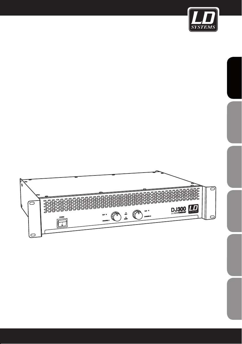
LD DJ SERIES
PA POWER AMPLIFIER
LDDJ300 / LDDJ500 / LDDJ800
Page 2
ENGLISHDEUTSCHFRANCAIS
Thank you for choosing LD Systems!
We have designed this product to operate reliably over many years. Therefore LD Systems guarantees for high
quality products with its name and many years of experience as a producer.
Please take a few moments to read these instructions carefully, as we want you to enjoy your new LD Systems
products quickly and to the fullest.
For information about LD Systems check out our website WWW.LD-SYSTEMS.COM
Introduction
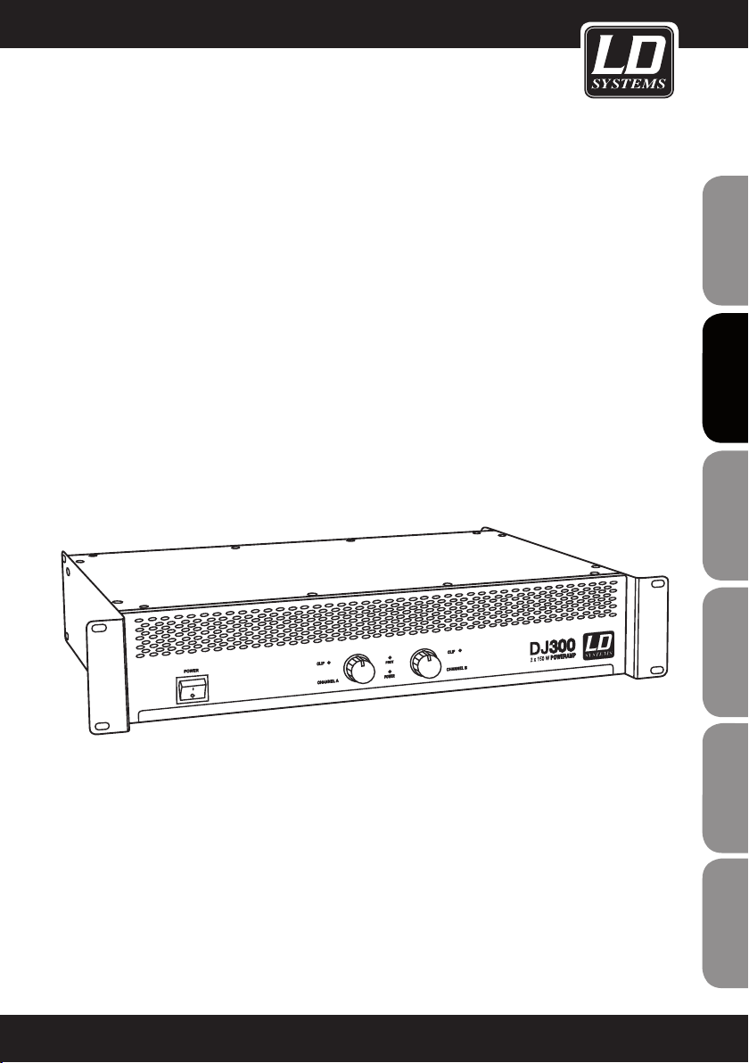
With the models of its DJ series, which represent a new design from the ground up, LD Systems is unveiling
three straightforward power amps with absolutely impressive operational reliability, rugged construction, and
ESPAÑOLPOLSKIITALIANO
outstanding value for money. The compact lightweights in 2HU rack format have output ratings of 150W to 400W
with a 4-ohm load per channel and can be used flexibly in all mobile applications and permanent installations.
This makes them an outstanding choice not only for DJs.
The DJ300, DJ500, and DJ800 model variants with the time-tested Class AB design have a frequency range of
20Hz-20kHz with high dynamics and impulse fidelity. They incorporate a thoroughly professional set of features:
the inputs are XLR and stereo TRS sockets that accept both balanced and unbalanced signals. Speakers can be
FRANCAISFRANCAIS
FRANCAISFRANCAIS
connected via Speakon-compatible outputs and sturdy screw terminals that also accept banana plugs.
The LD Systems DJ power amps are protected against short circuiting, DC, overheating, and overloading, and
have a power-on delay. A low-noise fan keeps them cool. LEDs on the front panel between the easy-grip level
controls clearly indicate power, clipping, activation of the protection circuit with various colours. The mains fuse
is integrated in the IEC socket. The features of the DJ series are rounded out by recessed switches for bridge
mode and ground lift to eliminate ground loop hum.
2
Page 3
LD DJ SERIES
FRANCAIS
FRANCAIS
ENGLISH
PA POWER AMPLIFIER
LDDJ300 / LDDJ500 / LDDJ800
DEUTSCH
FRANCAIS
FRANCAIS
FRANCAIS
ESPAÑOL
POLSKI
ITALIANO
3
Page 4

PREVENTIVE MEASURES:
1. Please read this information carefully.
2. Keep all information and instructions in a safe place.
3. Please follow the instructions.
ENGLISHDEUTSCHFRANCAIS
4. Please observe all warnings. Don‘t remove safety instructions or any other information located on the device.
5. Use the device only in the intended manner.
6. Use only stable and appropriate stands and/or mounts when the device is permanently installed. Make certain
that wall brackets are firmly secured. Make certain that the unit is installed securely and cannot fall down.
7. When installing please observe the corresponding safety standards for your country.
8. Do not install the device near radiators, heat accumulators, ovens or other sources of heat. Make certain that
the device is always installed so that is cooled sufficiently and cannot overheat.
9. Do not place open sources of ignition, e.g., burning candles, on the device.
10. Do not cover ventilation slots.
11. Do not operate the device in the immediate vicinity of water. Do not expose this equipment to combustible
materials, liquids or gases.
12. Please make certain that dripping or splashing water cannot get inside the device. Do not put objects filled
with fluids, such as vases or drinking vessels, on top of the device.
13. Make certain that objects cannot fall into the device.
14. Use the device only with accessories with which the manufacturer intends the device to be used.
15. CAUTION: If this device has a mains connector equipped with protective earth, it must be connected to a
mains socket with a protective ground connection. Never disable the function of the protective ground connection
of the included power cord.
16. Do not turn on the device immediately if it was exposed to strong temperature fluctuations (for example after
transportation). Moisture and condensation may damage the device. Leave the device switched off until it has
reached room temperature.
17. Do not open the device and do not make any changes to the device.
18. Before connecting to mains power, make certain that the mains voltage and the mains frequency are the
ESPAÑOLPOLSKIITALIANO
same as the operating values of the device (see type label). If the device is equipped with a supply voltage selector switch, make certain that the values of the device match the values of the mains power before connecting.
If the plug on the included cord does not fit your mains outlet, contact your electrician.
19. Make certain that the power cord is not stepped on. Protect the power cord against pinching, especially at
the device plug and the power plug.
20. In order to prevent damage or accidents, for example, due to tripping hazards, check all connections once
you have connected the device.
FRANCAISFRANCAIS
FRANCAISFRANCAIS
21. When connecting the device, make certain that the power plug remains readily accessible.
Always pull out the power plug when the device is not in use or when you clean the device. Disconnect the
power cord by pulling the plug not the cable. Never touch the power cable and power adapter with wet hands.
22. Avoid switching the device on and off at short intervals, because it may shorten the durability of the device.
23. IMPORTANT: Replace fuse only by fuse of same type and rating! If fuse blows repeatedly please contact
authorized service center!
24. In order to disconnect the device completely from the mains voltage, the power plug must be unplugged.
25. If your device is equipped with a Volex power connector, the matching Volex device plug must be unlocked
in order to disconnect it. This also means that a tug on the power cord can pull the device out of place, thus
causing personal injuries and/or property damage. Thus please make certain to route your cables carefully.
4
Page 5
PREVENTIVE MEASURES:
26. If there is a risk of lightning strike or during extended periods of disuse, unplug the power plug.
27. During transport, make certain that the equipment being transported cannot fall down and possibly
cause personal injuries and/or property damage.
28. If your device no longer works properly, if it has been exposed to liquids or an object has fallen inside it or
if it has been damaged in some other manner, turn the device off immediately und unplug the power plug. This
device should be repaired only by authorized experts.
29. Use only a dry cloth to clean the device.
30. Comply with all of the disposal laws that are applicable in your country. During disposal, please separate
plastic and paper/cardboard.
31. Plastic bags must be kept out of the reach of children.
FRANCAIS
FRANCAIS
ENGLISHENGLISH
DEUTSCH
FRANCAIS
FRANCAIS
CAUTION
RISK OF ELECTRIC SHOCK
DO NOT OPEN
CAUTION:
To reduce the risk of electric shock, do not remove cover (or back). No user serviceable parts inside. Refer
servicing to qualified personnel.
The lightning flash with arrowhead symbol within an equilateral triangle is intended to alert the
user to the presence of uninsulated “dangerous voltage” within the product´s enclosure that may be
of sufficient magnitude to constitute a risk to persons.
The exclamation mark within an equilateral triangle is intended to alert the user to the presence of
important operating and maintenance (servicing) instructions in the literature accompanying the
appliance.
CAUTION! HIGH VOLUME!
This product is designed for professional use. Therefore the commercial use of this equipment is liable to the
rules and regulations of the Accident Prevention & Insurance Association of your industry sector. Adam Hall as a
manufacturer is bound to inform you formally about the existence of eventual sanitary risks.
Risk of hearing damage due to prolonged exposure to excessive volumes: When using this product high sound
pressure levels (SPL) can be generated, sufficient to cause permanent hearing damage to performers, production
crew and audience members. Caution should be taken to avoid prolonged exposure SPL in excess of 90 dB.
FRANCAIS
ESPAÑOL
POLSKI
ITALIANO
5
Page 6
PREVENTIVE MEASURES:
DANGER AT THE SPEAKER OUTPUT!
Power amplifiers are capable of producing dangerously high voltages at the output. To avoid electrical shock,
ENGLISHDEUTSCHFRANCAIS
never touch bare speaker wires or terminal posts while the power amplifier is in operation.
INSTALLATION AND CONNECTION
For trouble-free operation, during setup and rack installation, make certain that the air intake and ventilation of
the power amplifier is not hampered (ventilation slits on the front panel, fan on the rear panel).
We recommend the use of high-quality balanced cables(with two conductors for the audio signal plus separate
shielding mesh) with XLR-type connectors for connecting the signal source (e.g., mixing desk) to the power
amplifier. While it is also possible to connect unbalanced cables to the power amplifier inputs, for reasons of
interference immunity, using balanced cables is always preferable.
In order to reduce power losses, speakers should always be connected using twinaxial speaker cable with a
sufficiently large cross-section.
ESPAÑOLPOLSKIITALIANO
FRANCAISFRANCAIS
FRANCAISFRANCAIS
6
Page 7
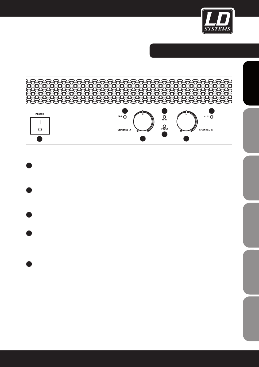
FRONT / CONTROLS:
FRANCAIS
FRANCAIS
ENGLISH
5
1
1
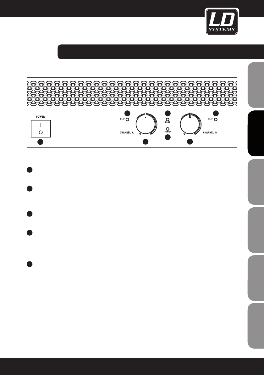
POWER SWITCH
Always turn the volume down to zero on both channels before turning the amplifier on and off (knobs all the
way to the left).
2
VOLUME CONTROLS CHANNEL A AND B
Turning the knob to the right increases and turning it to the left decreases the volume.
In bridge mode (BTL), the volume of the power amplifier is controlled by the volume control for Channel A.
3
POWER LED
Lights up if the speaker system is switched on and properly connected to the power mains.
4
CLIP LED CHANNEL A AND B
Lights up if the power amplifier is operating in the clipping range. This should be avoided by reducing the
input level, because otherwise distortion may result which can both have a negative effect on the resulting
sound and cause damage to the connected speakers.
5
PROTECT LED
Lights up after power-on as long as the power-on delay is active. After the Protect LED goes out, the power
amplifier is ready for operation.
The Protect LED lights up when one of the power amplifier protection circuits is active. To protect the power
amplifiers and the connected speakers, the speaker outputs are deactivated in protect mode. Once the
source of the trouble has been eliminated (e.g., overloading or a short circuit at the speaker output), after a
short time, the power amplifier returns to normal status, the Protect LED goes out, and the speaker outputs
are reactivated.
If the Protect LED does not go out after a short time even if all inputs and outputs have been disconnected,
there is an internal fault. In this case, turn off the power amplifier, disconnect it from the power mains, and
hand it over to an authorised service centre.
2 2
3
44
DEUTSCH
FRANCAIS
FRANCAIS
FRANCAIS
ESPAÑOL
POLSKI
ITALIANO
7
Page 8
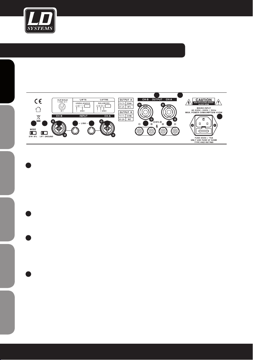
REAR PANEL / CONNECTORS & CONTROLS:
PICTURED: LDDJ300
ENGLISHDEUTSCHFRANCAIS
1
2
ESPAÑOLPOLSKIITALIANO
3
FRANCAISFRANCAIS
FRANCAISFRANCAIS
4
4 4
1
67
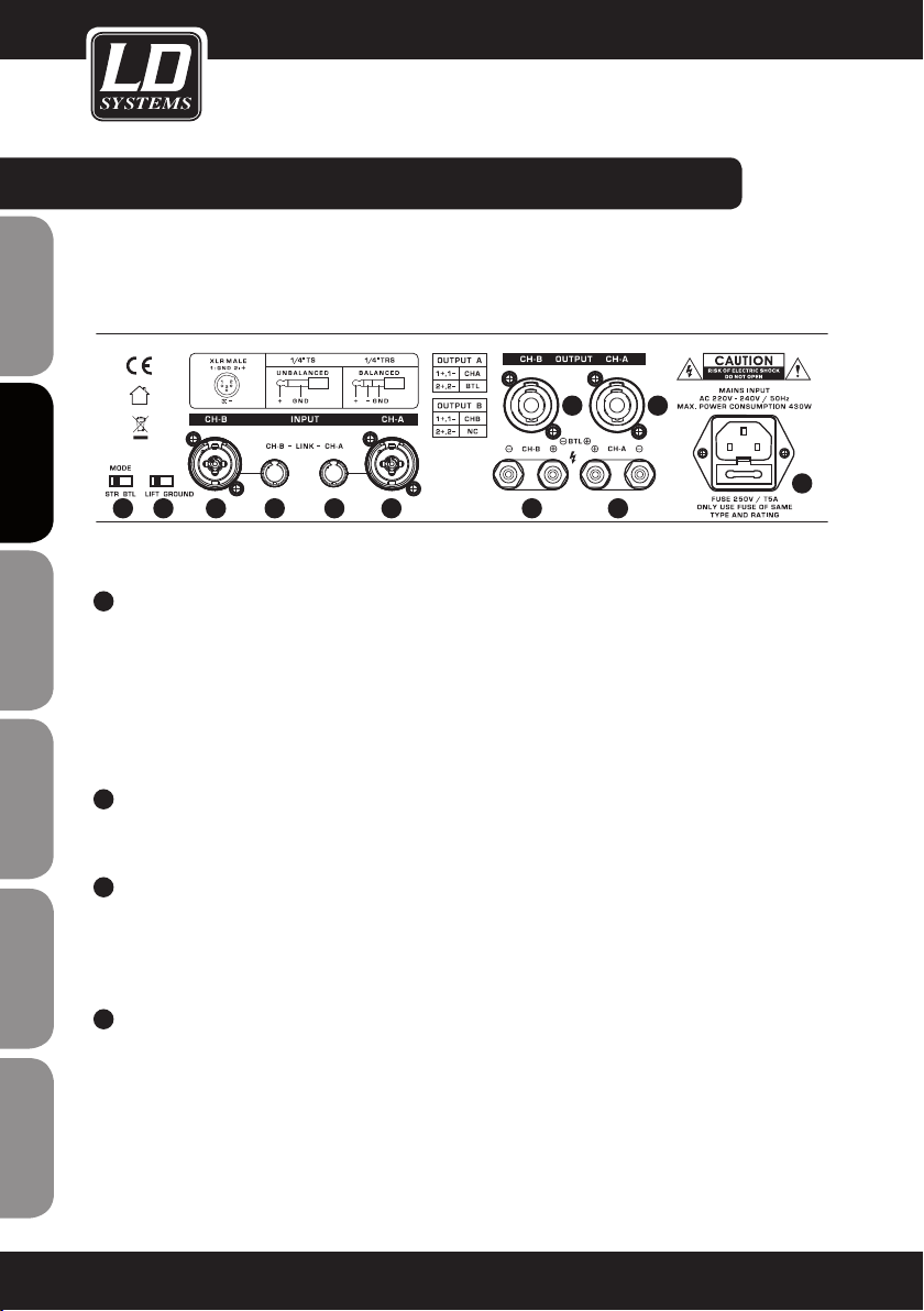
POWER CONNECTOR WITH FUSE HOLDER
Always make certain that the operating voltage of the power amplifier (printed on the rear panel of the power
amplifier) matches the mains voltage in your region. An appropriate mains cord is included in the package.
Always disconnect the power amplifier from the mains power during installation.
IMPORTANT INFORMATION: Always replace the fuse only with a fuse of the same type with the same rating
(printed on the rear panel of the power amplifier). If the fuse blows repeatedly, please contact an authorised
service centre.
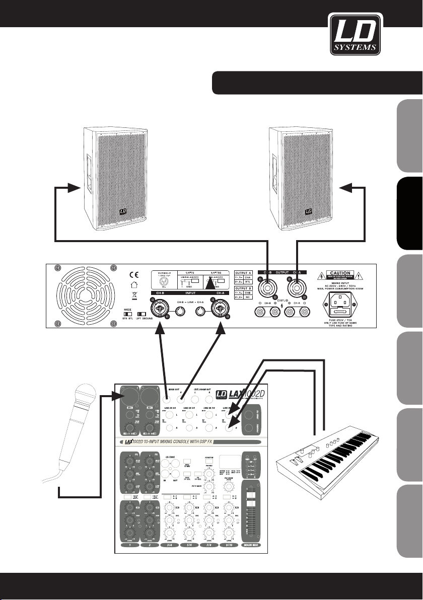
BALANCED XLR-INPUT CHANNEL A AND B
The XLR input sockets are used to connect to a mixing desk or another signal source.
In bridge mode BTL (bridge tied load), Channel A must be used as the input.
BALANCED JACK INPUT / LINK OUPUT
These 6.3 mm TRS sockets can be used as an audio input or to loop through the signals from the XLR
input sockets. Unbalanced instrument cables can also be used, but when looping through the signal with
unbalanced instrument cables, it is important to remember that this automatically makes the input signal of
the power amplifier unbalanced.
SPEAKON-COMPATIBLE SPEAKER OUTPUTS CHANNEL A AND B
Connection of speakers or speaker systems with a total impedance of at least 4 ohms per channel.
In bridge mode BTL (bridge tied load), the Channel A output socket must be used, whereby it must be ensured that pin 2+ and 2- of the Speakon-compatible sockets are used.
IMPORTANT: In bridge mode, the total impedance of the connected speaker system must not be less than 8
ohms.
33 5 522
8
Page 9
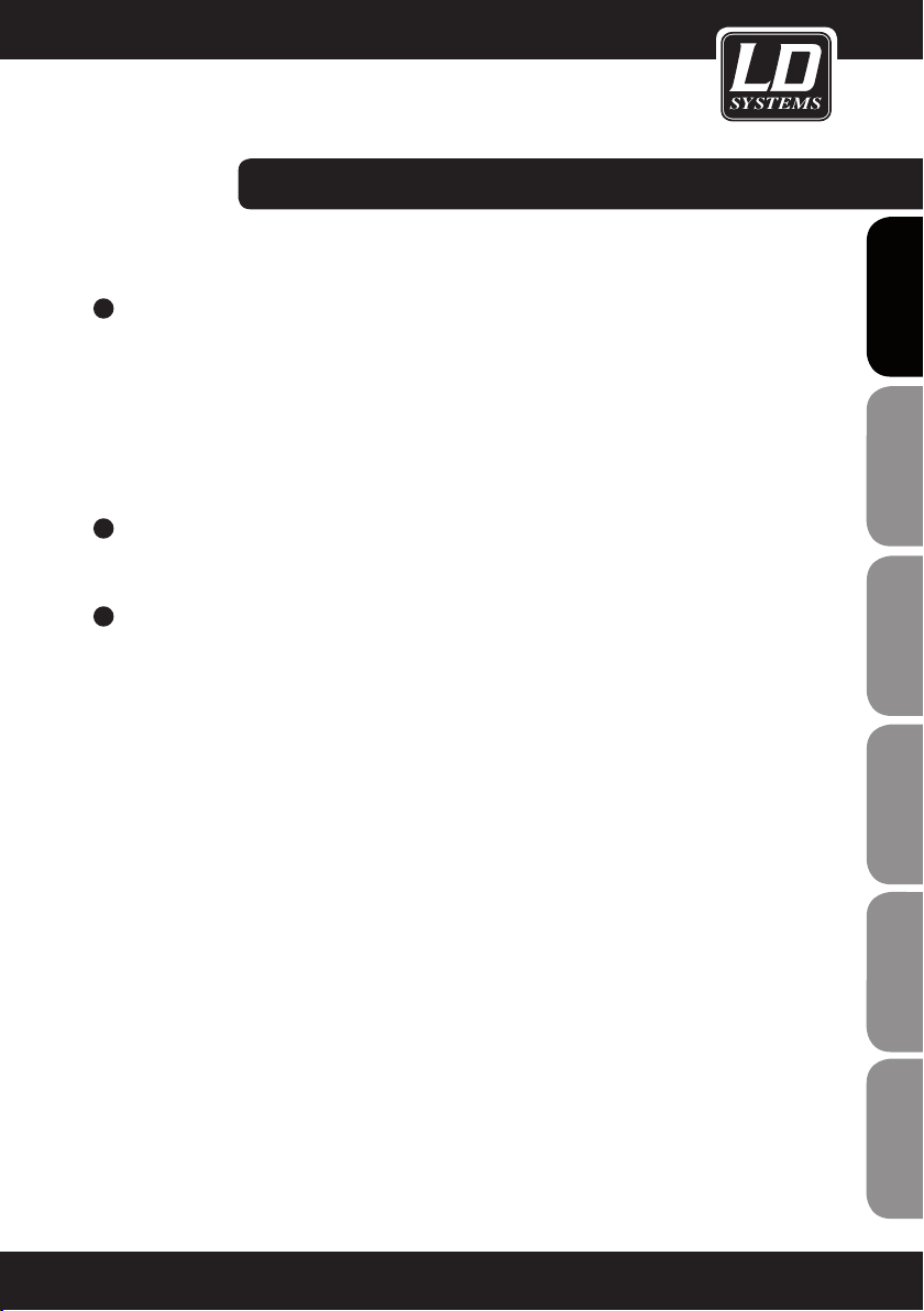
REAR PANEL / CONNECTORS & CONTROLS:
5
SPEAKER TERMINAL CLAMPS CHANNEL A AND B
Connection of speakers or speaker systems with a total impedance of at least 4 ohms per channel.
Connect the positive pole (+) of the speaker cable to the red terminal clamp (+) and the negative pole (-) of
the speaker cable to the black terminal clamp (-) of the respective channel. Optionally, speaker cables with
banana plugs can also be used.
In bridge mode BTL (bridge tied load), the red Channel A terminal clamp must used as the positive pole (+)
and the red Channel B terminal clamp must be used as the negative pole (-).
IMPORTANT: In bridge mode, the total impedance of the connected speaker system must not be less than 8
ohms.
6
GROUND-LIFT SWITCH
Used to avoid ground loops. In LIFT position, the connection between the housing and the signal ground is
interrupted.
7
MODE SWITCH
In STR position (stereo mode), output stages A and B operate independently. Both stereo signals and entirely
different signals can be amplified via Channel A and B.
In BTL position (bridge mode), output stages A and B are connected to a more powerful mono output stage.
IMPORTANT: In bridge mode, the total impedance of the connected speaker system must not be less than 8
ohms.
FRANCAIS
FRANCAIS
ENGLISH
DEUTSCH
FRANCAIS
FRANCAIS
FRANCAIS
ESPAÑOL
POLSKI
ITALIANO
9
Page 10
)elamef( RLX)elam( RLX
Sleeve
Tip
+
Tip
Ring
Sleeve
+
-
Tip
Ring
Sleeve
+
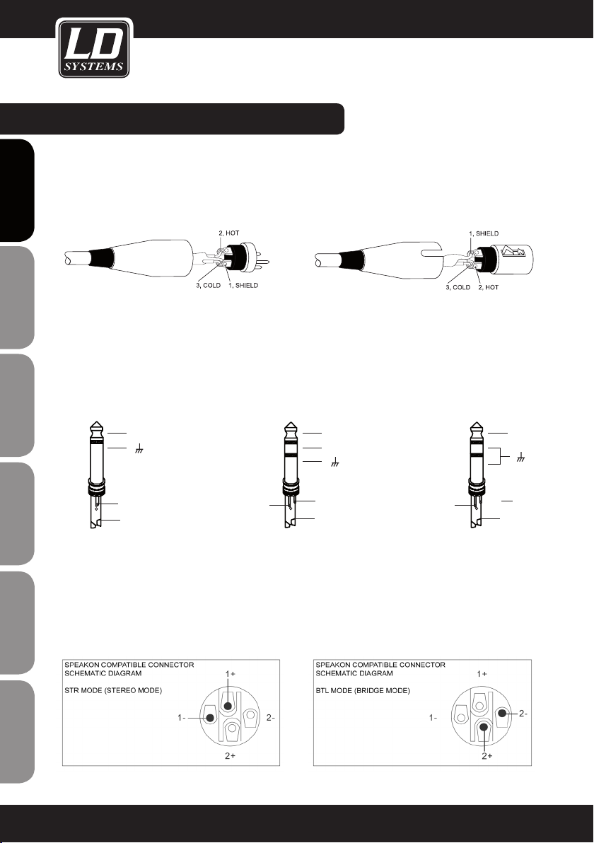
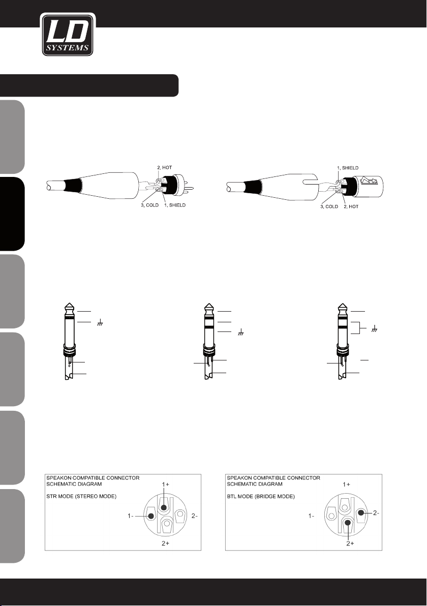
CONNECTOR PIN ASSIGNMENTS:
XLR-TYPE CONNECTOR PIN ASSIGNMENTS
ENGLISHDEUTSCHFRANCAIS
TRS CONNECTOR PIN ASSIGNMENTS
UNBALANCED BALANCED UNBALANCED
ESPAÑOLPOLSKIITALIANO
SPEAKON-COMPATIBLE CONNECTOR PIN ASSIGNMENTS
FRANCAISFRANCAIS
FRANCAISFRANCAIS
STR POSITION (STEREO MODE) BTL POSITION (BRIDGE MODE)
10
Page 11
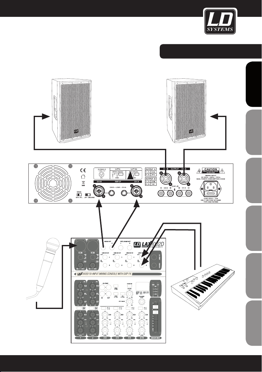
WIRING EXAMPLE:
FRANCAIS
FRANCAIS
ENGLISH
DEUTSCH
FRANCAIS
FRANCAIS
FRANCAIS
ESPAÑOL
POLSKI
ITALIANO
11
Page 12
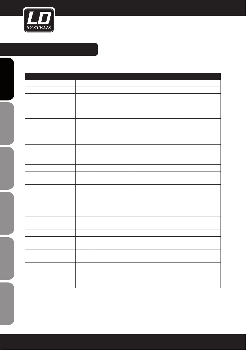
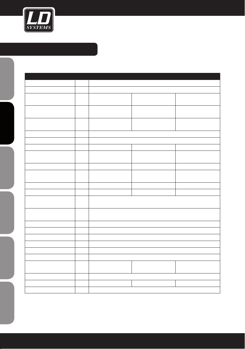
SPECIFICATIONS:
LDDJ300 LDDJ500 LDDJ800
Product type: Power amplifier
ENGLISHDEUTSCHFRANCAIS
Type: 2-channel
Output power (1 kHz @ 4
ohms):
Output power (1 kHz @ 8
ohms):
Output power (1 kHz @ 8
ohms, bridged mode):
Circuit concept: Class A/B
Frequency response: Hz 20 - 20.000
THD: 0,03% 0,04% 0,04%
S/N ratio: dB 74 88 98
Crosstalk: dB 70 71 72
Voltage gain: dB 28 30 32
Input sensitivity: V 1 1 1
Input impedance: kOhms 32 32 32
Protection: DC, overheating, short-circuit, overcurrent,
Controls: Power switch, Channel A volume, Channel B volume, ground lift,
Indicators: Power, Clip A, Clip B, Protect
Line in- / outputs: 2 x XLR, 2 x 6.3 mm jack
ESPAÑOLPOLSKIITALIANO
Speaker outputs: 2 x Speakon-compatible, 2 x terminal posts
Cooling system: low-noise fan
Power supply: transformer
Operating voltage: V 220 - 240 V AC, 50 Hz
Power consumption (at
full load):
FRANCAISFRANCAIS
FRANCAISFRANCAIS
Dimensions (W x H x D): mm 482 x 88 x 298
Weight: kg 8,5 9 10,1
Accessories included in
package:
W 2 x 150 2 x 250 2 x 400
W 2 x 100 2 x 150 2 x 240
W 250 500 800
power-on delay
bridge / stereo mode
W 430 690 1100
power cable, user manual
12
Page 13

MANUFACTURER´S DECLARATIONS:
LIMITED WARRANTY
This Limited Warranty applies to the Adam Hall, LD Systems, Defender, Palmer, Cameo and Eminence branded
products.
The statutory warranty rights towards the seller are not affected by this guarantee. In fact, it justifies, additional
independent warranty claims towards Adam Hall.
Adam Hall warrants that the Adam Hall product you have purchased from Adam Hall or from an Adam Hall authorized reseller is free from defects in materials or workmanship under normal use for a period of 2 or 3 years from
the date of purchase.
The Limited Warranty Period starts on the date of purchase. In order to receive warranty services you are required to provide proof of the purchase date. Your dated sales or delivery receipt, showing the date of purchase,
is your proof of the purchase date. Should products of the brands named above be in need of repair within the
limited warranty period, you are entitled to warranty services according to the terms and conditions stated in this
document.
This Limited Warranty extends only to the original purchaser of this Adam Hall branded product and is not transferable to anyone who obtains ownership of the Adam Hall branded product from the original purchaser. During
the Limited Warranty Period, Adam Hall will repair or replace the defective component parts or the product. All
component parts or hardware products removed under this Limited Warranty become the property of Adam Hall.
FRANCAIS
FRANCAIS
ENGLISH
DEUTSCH
FRANCAIS
FRANCAIS
FRANCAIS
In the unlikely event that your Adam Hall product has a recurring failure, Adam Hall, at its discretion, may elect to
provide you with a replacement unit of Adam Hall´s choice that is at least equivalent to your Adam Hall branded
product in hardware performance.
Adam Hall does not warrant that the operation of this product will be uninterrupted or error-free. Adam Hall is not
responsible for damage that occurs as a result of your failure to follow the instructions included with the Adam
Hall branded product.
This Limited Warranty does not apply,
- to wear parts (e.g. accumulator)
- to any product from which the serial number has been removed or that has been damaged or rendered defective as the result of an accident
- in case of, misuse, abuse, or other external causes
- by operation outside the usage parameters stated in the user´s documentation shipped with the product by use
of spare parts not manufactured or sold by Adam Hall
- by modification or service by anyone other than Adam Hall
These terms and conditions constitute the complete and exclusive warranty agreement between you and Adam
Hall regarding the Adam Hall branded product you have purchased.
ESPAÑOL
POLSKI
ITALIANO
13
Page 14
MANUFACTURER´S DECLARATIONS:
LIMITATION OF LIABILITY
If your Adam Hall branded hardware product fails to work as warranted above, your sole and exclusive remedy
shall be repair or replacement. Adam Halls’ maximum liability under this limited warranty is expressly limited
ENGLISHDEUTSCHFRANCAIS
to the lesser of the price you have paid for the product or the cost of repair or replacement of any hardware
components that malfunction in conditions of normal use.
Adam Hall is not liable for any damages caused by the product or the failure of the product, including any lost
profits or savings or special, incidental, or consequential damages. Adam Hall is not liable for any claim made by
a third party or made by you for a third party.
This limitation of liability applies whether damages are sought, or claims are made, under this Limited Warranty
or as a tort claim (including negligence and strict product liability), a contract claim, or any other claim. This limitation of liability cannot be waived or amended by any person. This limitation of liability will be effective even if
you have advised Adam Hall of an authorized representative of Adam Hall of the possibility of any such damages.
This limitation of liability however, will not apply to claims for personal injury.
This Limited Warranty gives you specific legal rights. You may also have other rights that may vary from state to
state or from country to country. You are advised to consult applicable state or country laws for a full determination of your rights.
REQUESTING WARRANTY-SERVICE
To request warranty service for the product, contact Adam Hall or the Adam Hall authorized reseller from which
you purchased the product.
EC DECLARATION OF CONFORMITY
ESPAÑOLPOLSKIITALIANO
These devices meet the essential requirements and further relevant specifications of Directives 2004/108/EC
(EMC) and 2006/95/EC (LVD). For more information, see www.adamhall.com.
CORRECT DISPOSAL OF THIS PRODUCT (ELECTRICAL WASTE)
(Applicable in the European Union and other European countries with separate collection systems)
This marking shown on the product or its literature, indicates that it should not be disposed with other household
wastes at the end of its working life. To prevent possible harm to the environment or human health from uncon-
FRANCAISFRANCAIS
FRANCAISFRANCAIS
trolled waste disposal, please separate this from other types of wastes and recycle it responsibly to promote the
sustainable reuse of material resources.
Household users should contact either the retailer where they purchased this product, or their local government
office, for details on where and how they can recycle this item in an enviromentally friendly manner.
Business users should contact their supplier and check the terms and conditions of the purchase contract. This
product should not be mixed with other commercial wastes for disposal.
14
Page 15
MANUFACTURER´S DECLARATIONS:
WEEE-DECLARATION
Your LD-Systems product was developed and manufactured with high quality materials and components wich
can be recycled and/or reused. This symbol indicates that electrical and electronic equipment must be disposed
of separately from normal waste at the end of its operational lifetime.
Please dispose of this product by bringing it to your local collection point or recycling centre for such equipment.
This will help to protect the environment in which we all live.
BATTERIES AND ACCUMULATORS
The supplied batteries or rechargeable batteries can be recycled. Please dispose of them as special waste or
return them to your specialist dealer. In order to protect the environment, only dispose exhausted batteries.
ECOLOGY AND ENERGY SAVING
Saving electric energy helps to protect the environment. Please turn off all electrical equipment when it is not in
use. To avoid power consuption in idle mode, disconnect all electrical equipment from mains when not in use.
FRANCAIS
FRANCAIS
ENGLISH
DEUTSCH
FRANCAIS
FRANCAIS
FRANCAIS
ESPAÑOL
Adam Hall GmbH, all rights reserved. The technical data and the functional product characteristics can be subject
to modifications. The photocopying, the translation, and all other forms of copying of fragments or of the integrality of this user’s manual is prohibited.
POLSKI
ITALIANO
15
Page 16
ENGLISHDEUTSCHFRANCAIS
Sie haben die richtige Wahl getroffen!
Diese LD Systems Produkte werden Sie lange Jahre durch Zuverlässigkeit, Wirtschaftlichkeit und einfaches
Handling überzeugen. Dafür garantiert LD Systems mit seinem Namen und seiner in vielen Jahren erworbenen
Kompetenz als Hersteller hochwertiger Geräte.
Nehmen Sie sich nun ein paar Minuten Zeit, diese Anleitung zu lesen. Wir möchten, dass Sie einfach
und schnell in den Genuss dieser Technik kommen.
Mehr Informationen zu LD SYSTEMS finden Sie auf unserer Internetseite WWW.LD-SYSTEMS.COM
Einführung
Mit den von Grund auf neu konzipierten Modellen der DJ-Serie stellt LD Systems drei schnörkellose Endstufen
vor, die mit zuverlässigem Betrieb, solider Konstruktion und einem hervorragenden Preis-Leistungs-Verhältnis
ESPAÑOLPOLSKIITALIANO
absolut überzeugen. Die kompakten Leichtgewichte im 2HE Rackformat warten mit Leistungen von 150W bis
400W an 4 Ohm pro Kanal auf und lassen sich flexibel in allen mobilen Anwendungen und Festinstallationen
einsetzen. Sie sind damit nicht nur für DJs eine ausgezeichnete Wahl.
Die Modellvarianten DJ300, DJ500 und DJ800 im bewährten Class AB-Design besitzen einen Übertragungsbereich von 20Hz – 20kHz mit hoher Dynamik und Impulstreue. Sie sind rundum professionell ausgestattet: die
Eingänge sind als XLR- und Stereo-Klinkenbuchsen ausgeführt, die sowohl symmetrisch als auch unsymmet-
FRANCAISFRANCAIS
FRANCAISFRANCAIS
risch belegt werden können. Zum Anschluß der Lautsprecher dienen Speakon-kompatible Ausgänge und kräftige
Schraubklemmen, die auch Bananenstecker aufnehmen.
16
Die LD Systems DJ-Endstufen sind gegen Kurzschluß, Gleichstrom, Überhitzung und Überlast geschützt und
verfügen über eine Einschaltverzögerung. Ein geräuscharmer Lüfter sorgt für Kühlung. Neben den griffigen
Pegelstellern zeigen LEDs auf der Front die Netzversorgung, Übersteuern und Ansprechen der Schutzschaltung
in unterschiedlichen Farben deutlich an. Die Netzsicherung ist in die IEC-Buchse integriert, versenkt montierte
Schalter für Brückenbetrieb und Ground Lift zur Beseitigung von Erdschleifen runden die Ausstattung der DJSerie ab.
Page 17
LD DJ SERIE
FRANCAIS
FRANCAIS
ENGLISH
PA ENDSTUFE
LDDJ300 / LDDJ500 / LDDJ800
DEUTSCH
FRANCAIS
FRANCAIS
FRANCAIS
ESPAÑOL
POLSKI
ITALIANO
17
Page 18
SICHERHEITSHINWEISE:
1. Lesen Sie diese Anleitung bitte sorgfältig durch.
2. Bewahren Sie alle Informationen und Anleitungen an einem sicheren Ort auf.
3. Befolgen Sie die Anweisungen.
ENGLISHDEUTSCHFRANCAIS
4. Beachten Sie alle Warnhinweise. Entfernen Sie keine Sicherheitshinweise oder andere Informationen vom Gerät.
5. Verwenden Sie das Gerät nur in der vorgesehenen Art und Weise.
6. Verwenden Sie ausschließlich stabile und passende Stative bzw. Befestigungen (bei Festinstallationen). Stellen
Sie sicher, dass Wandhalterungen ordnungsgemäß installiert und gesichert sind. Stellen Sie sicher, dass das
Gerät sicher installiert ist und nicht herunterfallen kann.
7. Beachten Sie bei der Installation die für Ihr Land geltenden Sicherheitsvorschriften.
8. Installieren und betreiben Sie das Gerät nicht in der Nähe von Heizkörpern, Wärmespeichern, Öfen oder
sonstigen Wärmequellen. Sorgen Sie dafür, dass das Gerät immer so installiert ist, dass es ausreichend gekühlt
wird und nicht überhitzen kann.
9. Platzieren Sie keine Zündquellen wie z.B. brennende Kerzen auf dem Gerät.
10. Lüftungsschlitze dürfen nicht blockiert werden.
11. Betreiben Sie das Gerät nicht in unmittelbarer Nähe von Wasser. Bringen Sie das Gerät nicht mit brennbaren
Materialien, Flüssigkeiten oder Gasen in Berührung.
12. Sorgen Sie dafür, dass kein Tropf- oder Spritzwasser in das Gerät eindringen kann. Stellen Sie keine mit
Flüssigkeit gefüllten Behältnisse wie Vasen oder Trinkgefäße auf das Gerät.
13. Sorgen Sie dafür, dass keine Gegenstände in das Gerät fallen können.
14. Betreiben Sie das Gerät nur mit dem vom Hersteller empfohlenen und vorgesehenen Zubehör.
15. ACHTUNG: Wenn das Netzkabel des Geräts mit einem Schutzkontakt ausgestattet ist, muss es an einer
Steckdose mit Schutzleiter angeschlossen werden. Deaktivieren Sie niemals den Schutzleiter eines Netzkabels.
16. Schalten Sie das Gerät nicht sofort ein, wenn es starken Temperaturschwankungen ausgesetzt war (beispielsweise nach dem Transport). Feuchtigkeit und Kondensat könnten das Gerät beschädigen. Schalten Sie das
Gerät erst ein, wenn es Zimmertemperatur erreicht hat.
17. Öffnen Sie das Gerät nicht und verändern Sie es nicht.
ESPAÑOLPOLSKIITALIANO
18. Bevor Sie das Gerät an die Steckdose anschließen, prüfen Sie zuerst, ob die Spannung und die Frequenz
des Stromnetzes mit den auf dem Gerät angegebenen Werten übereinstimmen. Verfügt das Gerät über einen
Spannungswahlschalter, schließen Sie das Gerät nur an die Steckdose an, wenn die Gerätewerte mit den Werten
des Stromnetzes übereinstimmen.
Wenn das mitgelieferte Netzkabel bzw. der mitgelieferte Netzadapter nicht in Ihre Netzsteckdose passt, wenden
Sie sich an Ihren Elektriker.
19. Treten Sie nicht auf das Netzkabel. Sorgen Sie dafür, dass spannungsführende Kabel speziell an der Netz-
FRANCAISFRANCAIS
FRANCAISFRANCAIS
buchse bzw. am Netzadapter und der Gerätebuchse nicht geknickt werden.
20. Überprüfen Sie nach dem Anschluss des Geräts alle Kabelwege, um Schäden oder Unfälle, z. B. durch
Stolperfallen zu vermeiden.
21. Achten Sie bei der Verkabelung des Geräts immer darauf, dass das Netzkabel bzw. der Netzadapter stets frei
zugänglich ist. Trennen Sie das Gerät stets von der Stromzuführung, wenn das Gerät nicht benutzt wird, oder Sie
das Gerät reinigen möchten.
Ziehen Sie Netzkabel und Netzadapter immer am Stecker bzw. am Adapter und nicht am Kabel aus der Steckdose. Berühren Sie Netzkabel und Netzadapter niemals mit nassen Händen.
22. Schalten Sie das Gerät möglichst nicht schnell hintereinander ein und aus, da sonst die Lebensdauer des
Geräts beeinträchtigt werden könnte.
18
Page 19

SICHERHEITSHINWEISE:
23. WICHTIGER HINWEIS: Ersetzen Sie Sicherungen ausschließlich durch Sicherungen des gleichen Typs
und Werten. Sollte eine Sicherung wiederholt auslösen, wenden Sie sich bitte an ein autorisiertes Servicezentrum.
24. Um das Gerät vollständig vom Stromnetz zu trennen, entfernen Sie das Netzkabel bzw. den Netzadapter aus
der Steckdose.
25. Wenn Ihr Gerät mit einem Volex-Netzanschluss bestückt ist, muss der passende Volex-Gerätestecker
entsperrt werden, bevor er entfernt werden kann. Das bedeutet aber auch, dass das Gerät durch eine Ziehen
am Netzkabel verrutschen und herunterfallen kann, wodurch Personen verletzt werden und/oder andere Schäden
auftreten können. Verlegen Sie Ihre Kabel daher immer sorgfältig.
26. Entfernen Sie Netzkabel und Netzadapter aus der Steckdose bei Gefahr eines Blitzschlags oder wenn Sie das
Gerät länger nicht verwenden.
27. Achten Sie beim Transport darauf, dass das Gerät nicht herunterfallen und dabei möglicherweise Sach- und
Personenschäden verursachen kann.
28. Wenn Ihr Gerät nicht mehr ordnungsgemäß funktioniert, Flüssigkeiten oder Gegenstände in das Geräteinnere gelangt sind, oder das Gerät anderweitig beschädigt wurde, schalten Sie es sofort aus und trennen es von
der Netzsteckdose. Dieses Gerät darf nur von autorisiertem Fachpersonal repariert werden.
29. Verwenden Sie zur Reinigung des Geräts ein trockenes Tuch.
30. Beachten Sie alle in Ihrem Land geltenden Entsorgungsgesetze. Trennen Sie bei der Entsorgung bitte Kunststoff und Papier bzw. Kartonagen voneinander.
31. Kunststoffbeutel müssen außer Reichweite von Kindern aufbewahrt werden.
CAUTION
RISK OF ELECTRIC SHOCK
ACHTUNG:
Entfernen Sie niemals die Abdeckung, da sonst das Risiko eines elektrischen Schlages besteht. Im Inneren des
Geräts befinden sich keine Teile, die vom Bediener repariert oder gewartet werden können. Lassen Sie Reparaturen ausschließlich von qualifiziertem Service-Personal durchführen.
DO NOT OPEN
FRANCAIS
FRANCAIS
ENGLISH
ENGLISH
DEUTSCH
FRANCAIS
FRANCAIS
FRANCAIS
ESPAÑOL
Das gleichschenkelige Dreieck mit dem Blitzsymbol kennzeichnet
nicht-isolierte, „gefährliche“ Spannungen im Gerät,
die einen für die Gesundheit gefährlichen Stromschlag verursachen können.
Das gleichschenkelige Dreieck mit dem Ausrufezeichen kennzeichnet wichtige Bedienungs- und
Wartungshinweise
ACHTUNG! HOHE LAUTSTÄRKEN!
Dieses Gerät ist für den professionellen Einsatz vorgesehen. Der kommerzielle Betrieb dieses Geräts unterliegt
den jeweils gültigen nationalen Vorschriften und Richtlinien zur Unfallverhütung. Als Hersteller ist Adam Hall
gesetzlich verpflichtet, Sie ausdrücklich auf mögliche Gesundheitsrisiken hinzuweisen.
Gehörschäden durch hohe Lautstärken und Dauerbelastung: Bei der Verwendung dieses Produkts können hohe
Schalldruckpegel (SPL) erzeugt werden, die bei Künstlern, Mitarbeitern und Zuschauern zu irreparablen Gehörschäden führen können. Vermeiden Sie länger anhaltende Belastung durch hohe Lautstärken über 90 dB.
POLSKI
ITALIANO
19
Page 20

SICHERHEITSHINWEISE:
GEFAHREN AM LAUTSPRECHERAUSGANG!
Endstufen sind in der Lage, gefährlich hohe Spannungen am Ausgang zu produzieren. Zur Vermeidung eines
ENGLISHDEUTSCHFRANCAIS
Stromschlags berühren Sie keinesfalls blanke Lautsprecherleitungen, oder Polklemmen während des Betriebs
der Endstufe.
INSTALLATION UND VERKABELUNG
Für einen störungsfreien Betrieb ist bei Aufstellung und Rackeinbau unbedingt darauf zu achten, dass die
Luftzufuhr und die Entlüftung der Endstufe nicht behindert wird (Lüftungsschlitze auf der Vorderseite, Lüfter auf
der Rückseite).
Wir empfehlen den Einsatz hochwertiger, symmetrischer NF-Kabel (mit zwei Leitern für das Audiosignal plus separater Abschirmung) mit XLR-Steckverbindern um die Signalquelle (z.B. Mischpult) mit der Endstufe zu verbinden.
Es ist zwar auch möglich, unsymmetrische Kabel an den Endstufeneingängen anzuschließen, aus Gründen der
Störfestigkeit sollte jedoch der Verwendung symmetrischer Kabel grundsätzlich der Vorzug gegeben werden.
Um Leistungsverluste zu minimieren, sind für die Verkabelung von Lautsprechern twinaxiale Lautsprecherkabel
mit ausreichend großem Querschnitt zu verwenden.
ESPAÑOLPOLSKIITALIANO
FRANCAISFRANCAIS
FRANCAISFRANCAIS
20
Page 21
FRONT / BEDIENELEMENTE:
FRANCAIS
FRANCAIS
ENGLISH
5
1
1
NETZSCHALTER
Vor dem Ein- und Ausschalten stets die Lautstärke beider Kanäle auf Null drehen (Regler auf Linksanschlag).
2
LAUTSTÄRKEREGLER KANAL A UND B
Nach rechts gedreht erhöht sich, nach links gedreht verringert sich die Lautstärke.
In der Bridge Betriebsart (BTL) wird die Lautstärke der Endstufe von Lautstärkeregler Kanal A kontrolliert.
3
POWER LED
Leuchtet auf, wenn die Endstufe eingeschaltet und korrekt am Stromnetz angeschlossen ist.
4
CLIP LED KANAL A UND B
Leuchtet auf, sobald die Endstufe im Grenzbereich betrieben wird. Das sollte durch Absenken des Eingangspegels vermieden werden, da sonst Verzerrungen entstehen, die zum einen das Klangergebnis negativ
beeinflussen und zum anderen Schäden an angeschlossenen Lautsprechern verursachen können.
5
PROTECT LED
Leuchtet nach dem Einschalten auf, solange die Einschaltverzögerung aktiv ist. Nach dem Erlöschen der Protect
LED ist die Endstufe betriebsbereit.
Die Protect LED leuchtet auf, wenn eine der Schutzschaltungen in der Endstufe aktiv ist. Um die Leistungsverstärker und angeschlossene Lautsprecher zu schützen, werden im Protect Modus die Lautsprecherausgänge
abgeschaltet. Wird die Fehlerquelle beseitigt (z.B. Überlast, oder Kurzschluss am Lautsprecherausgang), kehrt
die Endstufe nach kurzer Zeit in den Normalzustand zurück, die Protect LED erlischt und die Lautsprecherausgänge werden wieder eingeschaltet.
Erlischt die Protect LED nach kurzer Zeit selbst dann nicht, wenn sowohl eingangs- als auch ausgangsseitig alle
Verbindungen getrennt wurden, liegt ein interner Fehler vor. Die Endstufe ist in diesem Fall auszuschalten, vom
Netz zu nehmen und einem autorisierten Servicezentrum zu übergeben.
2 2
3
44
DEUTSCH
FRANCAIS
FRANCAIS
FRANCAIS
ESPAÑOL
POLSKI
ITALIANO
21
Page 22
RÜCKSEITE / ANSCHLÜSSE & BEDIENELEMENTE:
ABGEBILDET: LDDJ300
ENGLISHDEUTSCHFRANCAIS
4 4
33 5 522
ESPAÑOLPOLSKIITALIANO
67
1
NETZBUCHSE MIT SICHERUNGSHALTER
Vergewissern Sie sich stets, dass die Betriebsspannung der Endstufe (Aufdruck auf der Rückseite der Endstufe) der in Ihrer Region geltenden Netzspannung entspricht. Ein geeignetes Netzkabel ist im Lieferumfang
enthalten.
Trennen Sie die Endstufe während der Installation immer von der Netzversorgung.
WICHTIGER HINWEIS: Ersetzen Sie die Sicherung ausschließlich durch eine Sicherung des gleichen Typs und
mit gleichen Werten (Aufdruck auf der Rückseite der Endstufe). Sollte die Sicherung wiederholt durchbrennen, wenden Sie sich bitte an ein autorisiertes Servicezentrum.
2
SYMMETRISCHER XLR-EINGANG KANAL A UND B
Die XLR Eingangsbuchsen dienen der Verbindung mit einem Mischpult oder einer anderen Signalquelle.
Im Bridge Modus BTL (Bridge Tied Load) muss Kanal A als Eingang verwendet werden.
1
FRANCAISFRANCAIS
FRANCAISFRANCAIS
22
3
SYMMETRISCHER KLINKENEINGANG / LINK AUSGANG
Diese 6,3 mm Klinkenbuchsen können wahlweise als Audioeingang, oder zum Weiterschleifen der an den
XLR Eingangsbuchsen anliegenden Signale genutzt werden. Es können auch unsymmetrische Klinkenkabel
verwendet werden, wobei zu beachten ist, dass beim Weiterschleifen des Signals mit unsymmetrischen
Klinkenkabeln die Ansteuerung der Endstufe automatisch unsymmetrisch wird.
4
SPEAKON KOMPATIBLE LAUTSPRECHERAUSGÄNGE KANAL A UND B
Anschluss von Lautsprechern bzw. Lautsprechersystemen von mindestens 4 Ohm Gesamtimpedanz pro Kanal.
Im Bridge Modus BTL (Bridge Tied Load) muss Ausgangsbuchse Kanal A verwendet werden, wobei darauf zu
achten ist, dass Pin 2+ und 2- der Speakon kompatiblen Buchse belegt sind.
WICHTIG: Im Bridge Modus darf die Gesamtimpedanz des angeschlossenen Lautsprechersystems 8 Ohm
nicht unterschreiten.
Page 23
RÜCKSEITE / ANSCHLÜSSE & BEDIENELEMENTE:
5
LAUTSPRECHERKLEMMANSCHLUSS KANAL A UND B
Anschluss von Lautsprechern bzw. Lautsprechersystemen von mindestens 4 Ohm Gesamtimpedanz pro Kanal.
Verbinden Sie den Pluspol (+) des Lautsprecherkabels mit dem roten Klemmanschluss (+) und den Minuspol
(-) des Lautsprecherkabels mit dem schwarzen Klemmanschluss (-) des jeweiligen Kanals. Wahlweise können
auch Lautsprecherkabel mit Bananensteckern verwendet werden.
Im Bridge Modus BTL (Bridge Tied Load) müssen roter Klemmanschluss Kanal A als Pluspol (+) und roter
Klemmanschluss Kanal B als Minuspol (-) verwendet werden.
WICHTIG: Im Bridge Modus darf die Gesamtimpedanz des angeschlossenen Lautsprechersystems 8 Ohm nicht
unterschreiten.
6
GROUND-LIFT SCHALTER
Dient zur Vermeidung von Brummschleifen. In LIFT-Stellung ist die Verbindung der Gehäuse- und der Signalmasse getrennt.
7
MODE SCHALTER
In STR-Stellung (Stereo Modus) arbeiten Endstufen A und B unabhängig voneinander. Es können sowohl StereoSignale als auch völlig unterschiedliche Signale über Kanal A und B verstärkt werden.
In BTL-Stellung (Bridge Modus) werden Enstufen A und B zu einer leistungsstärkeren Mono-Endstufe verschaltet.
WICHTIG: Im Bridge Modus darf die Gesamtimpedanz des angeschlossenen Lautsprechersystems 8 Ohm nicht
unterschreiten.
FRANCAIS
FRANCAIS
ENGLISH
DEUTSCH
FRANCAIS
FRANCAIS
FRANCAIS
ESPAÑOL
POLSKI
ITALIANO
23
Page 24
)elamef( RLX)elam( RLX
Sleeve
Tip
+
Tip
Ring
Sleeve
+
-
Tip
Ring
Sleeve
+
STECKERBELEGUNG:
BELEGUNG XLR-STECKER
ENGLISHDEUTSCHFRANCAIS
BELEGUNG KLINKENSTECKER
UNSYMMETRISCH SYMMETRISCH UNSYMMETRISCH
ESPAÑOLPOLSKIITALIANO
BELEGUNG SPEAKON KOMPATIBLE ANSCHLÜSSE
FRANCAISFRANCAIS
FRANCAISFRANCAIS
STR STELLUNG (STEREO MODUS) BTL STELLUNG (BRIDGE MODUS)
24
Page 25
VERKABELUNGSBEISPIEL:
FRANCAIS
FRANCAIS
ENGLISH
DEUTSCH
FRANCAIS
FRANCAIS
FRANCAIS
ESPAÑOL
POLSKI
ITALIANO
25
Page 26
SPEZIFIKATIONEN:
LDDJ300 LDDJ500 LDDJ800
Produktart: Endstufe
ENGLISHDEUTSCHFRANCAIS
Typ: 2-Kanal
Ausgangsleistung (1 kHz
@ 4 Ohm):
Ausgangsleistung (1 kHz
@ 8 Ohm):
Ausgangsleistung (1 kHz
@ 8 Ohm, Bridge-Modus):
Schaltungskonzept: Class A/B
Frequenzgang: Hz 20 - 20.000
Klirrfaktor (THD): 0,03% 0,04% 0,04%
Geräuschspannungsab-
stand:
Übersprechen: dB 70 71 72
Spannungsverstärkung
(Gain):
Eingangsempfindlichkeit: V 1 1 1
Eingangsimpedanz: kOhm 32 32 32
Schutzschaltungen: Gleichspannung, Überhitzung, Kurzschluss, Überstrom,
Bedienelemente: Netzschalter, Lautstärke Kanal A, Lautstärke Kanal B, Ground lift,
ESPAÑOLPOLSKIITALIANO
Anzeigeelemente: Power, Clip A, Clip B, Protect
Line-Ein- / Ausgänge: 2 x XLR, 2 x 6,3 mm Klinke
Lautsprecherausgänge: 2 x Speakon kompatibel, 2 x Polklemmen
Kühlung: geräuscharmer Lüfter
Stromversorgung: Transformator
Betriebsspannung: V 220 - 240 V AC, 50 Hz
FRANCAISFRANCAIS
FRANCAISFRANCAIS
Leistungsaufnahme (bei
Volllast):
Abmessungen (B x H x T): mm 482 x 88 x 298
Gewicht: kg 8,5 9 10,1
Zubehör im Lieferumfang: Netzkabel, Bedienungsanleitung
W 2 x 150 2 x 250 2 x 400
W 2 x 100 2 x 150 2 x 240
W 250 500 800
dB 74 88 98
dB 28 30 32
Einschaltverzögerung
Bridge- / Stereo Modus
W 430 690 1100
26
Page 27

HERSTELLERERKLÄRUNGEN:
GARANTIEBESTIMMUNGEN
Diese Garantie erstreckt sich auf die Marken Adam Hall, LD Systems, LD Premium, Defender, Palmer, Cameo und
Eminence.
Die gesetzlichen Gewährleistungsrechte gegenüber dem Verkäufer werden von dieser Garantie nicht berührt. Vielmehr begründet diese Garantie zusätzliche selbständige Ansprüche gegenüber Adam Hall.
Mit dieser Garantie stellt Adam Hall sicher, dass das von Ihnen bei Adam Hall oder einem Adam Hall Partner
erworbene Produkt bei normalem Gebrauch während des Zeitraums von 2 bzw. 3 Jahren ab Kaufdatum frei von
Material- oder Verarbeitungsfehlern ist.
Der Garantiezeitraum beginnt mit dem Datum des Kaufs.
Der Geltendmachung eines Anspruchs auf Garantieleistungen erforderliche Nachweis des Kaufdatums, erfolgt
durch die mit dem Kaufdatum versehene Quittung oder den mit dem Kaufdatum versehenen Lieferschein. Sie haben Anspruch auf den Garantieservice zu den in diesem Dokument aufgeführten Bedingungen und Bestimmungen,
falls eine Reparatur der unter den oben genanten Marken vertriebenen Produkte innerhalb des Garantiezeitraums
erforderlich ist.
Diese Garantie gilt nur für den ursprünglichen Käufer des von Adam Hall vertriebenen Produkts und ist nicht an
Personen übertragbar, denen vom ursprünglichen Käufer das Eigentum am Adam Hall Produkt übertragen wird.
Innerhalb des Garantiezeitraums werden die fehlerhaften Komponenten oder das Produkt von Adam Hall repariert
oder ersetzt. Alle im Rahmen dieser Garantie entfernten Komponenten und Hardware-Produkte gehen in das Eigentum von Adam Hall über.
In dem unwahrscheinlichen Fall, dass bei dem von Ihnen erworbenen Adam Hall Produkt ein Fehler wiederholt auftritt, kann Adam Hall nach eigenem Ermessen entscheiden, Ihnen dieses Produkt durch ein vergleichbares Produkt
mit mindestens derselben Leistung zu ersetzen.
FRANCAIS
FRANCAIS
ENGLISH
DEUTSCH
FRANCAIS
FRANCAIS
FRANCAIS
ESPAÑOL
Adam Hall übernimmt keine Garantie für einen störungs- oder fehlerfreien Betrieb dieses Produkts. Adam Hall
übernimmt keine Verantwortung für auf eine inkorrekte Befolgung der im Lieferumfang des Adam Hall enthaltenen
Anweisungen zurückzuführenden Schäden.
Diese Garantie erstreckt sich nicht auf
-Verschleißteile (z.B. Akkumulator).
-Geräte deren Seriennummer entfernt wurde oder die beschädigt oder fehlerhaft wurden als folge eines Unfalls.
-nicht sachgerechter oder missbräuchlicher Verwendung oder anderer missbräuchlicher Verwendung oder anderer
äußerer Ursachen.
-Geräte die nicht entsprechend den Betriebsparametern betrieben wurden, die in den im Lieferumfang des Produkts enthaltenen Benutzerunterlagen festgelegt sind.
-Geräte die aufgrund der Verwendung nicht von Adam Hall hergestellter oder vertriebener Teile repariert wurden.
-Geräte die durch Änderung oder Wartung durch jemand anderen als Adam Hall getätigt wurde.
POLSKI
ITALIANO
27
Page 28

HERSTELLERERKLÄRUNGEN:
Diese Bestimmungen und Bedingungen stellen die vollständige und ausschließliche Garantievereinbarung zwischen Ihnen und Adam Hall für das von Ihnen erworbene Adam Hall Produkt dar.
ENGLISHDEUTSCHFRANCAIS
HAFTUNGSBESCHRÄNKUNG
Wenn das unter der Marke Adam Hall vertriebene Produkt nicht entsprechend der obigen Garantie funktioniert,
besteht Ihr alleiniger und ausschließlicher Anspruch aus dieser Garantie in der Reparatur oder dem Ersatz.
Weitergehende Gewährleistungsansprüche bleiben hiervon unberührt. Die maximale Haftung von Adam Hall im
Rahmen dieser Garantie ist ausdrückliche beschränkt auf den jeweils niedrigeren Betrag, der sich entweder aus
dem Kaufpreis für das Produkt oder aus den Reparatur- bzw. Ersatzkosten von Hardware-Komponenten, die bei
normalem Gebrauch nicht Ordnungsgemäß funktionieren, ergibt.
Adam Hall haftet aus dieser Garantie nicht für durch das Produkt oder sein versagen verursachte Schäden, einschließlich entgangener Gewinne, unterbliebener Einsparungen oder besonderer, indirekter oder Folgeschäden.
Adam Hall haftet zudem nicht für von Dritten oder von ihnen für Dritte geltend gemachte Ansprüche.
Diese Haftungsbeschränkung gilt unabhängig davon, ob Schäden gerichtlich verfolgt werden, ob Schadensersatzansprüche im Rahmen dieser Garantie oder aufgrund unerlaubter Handlungen (Einschließlich Fahrlässigkeit
und Gefährdungshaftung) oder aufgrund vertraglicher bzw. sonstiger Ansprüche gestellt werden. Diese Haftungsbeschränkung kann von keiner Person aufgehoben oder ergänzt werden. Diese Haftungsbeschränkung gilt auch
dann, wenn sie Adam Hall über die Möglichkeit derartiger Schäden informiert haben. Sie gilt jedoch nicht für
Ansprüche aus Personenschäden.
Aus dieser Garantie ergeben sich für Sie bestimmte Rechte. Möglicherweise haben Sie weitere Rechte, die Ihnen
von Staat zu Staat und von Land zu Land unterschiedlich sein können. Es ist ratsam, die entsprechenden Gesetze
des Staates bzw. Landes heranzuziehen, um Ihre Rechte umfassend zu ermitteln.
ESPAÑOLPOLSKIITALIANO
INANSPRUCHNAHME DES REPARATURSERVICE
Um den Garantieservice bzw. Reparaturservice für das Produkt in Anspruch zu nehmen, wenden Sie sich bitte an
Adam Hall oder an einen Adam Hall Partner, bei dem Sie das Produkt erworben haben.
EG-KONFORMITÄTSERKLÄRUNG
Diese Geräte entsprechen den grundlegenden Anforderungen und den weiteren Vorgaben der Richtlinien
FRANCAISFRANCAIS
FRANCAISFRANCAIS
2004/108/EC (EMC) und 2006/95/EC (LVD). Weitere Informationen finden Sie unter www.adamhall.com.
KORREKTE ENTSORGUNG DIESES PRODUKTES
(Gültig in der Europäischen Union)
Dieses Symbol (entweder auf dem Gerät oder dem dazugehörigen Handbuch) weist darauf hin, dass das Gerät
nicht mit dem normalen Hausmüll entsorgt werden darf. Um mögliche Schäden an der Umwelt und an Personen
zu verhindern, entsorgen Sie dieses Gerät bitte fachgerecht bei einer entsprechenden Stelle für Elektromüll.
Als Privatkunde Informieren Sie sich bitte beim Hersteller oder bei Ihrer Gemeinde über die Möglichkeiten der
korrekten Entsorgung.
28
Page 29

HERSTELLERERKLÄRUNGEN:
Als Geschäftskunde kontaktieren Sie bitte Ihren Lieferanten und prüfen Sie die Konditionen zur Entsorgung der
Geräte. Dieses Produkt sollte nicht mit anderem gewerblichen Abfall entsorgt werden.
WEEE-DEKLARATION
Ihr LD-Systems Produkt wurde unter der Verwendung hochwertiger Materialien und Komponenten die wiedeverwertet oder wieder verwendet werden können hergestellt. Dieses Symbol weist darauf hin, dass elektronische
Geräte nicht im normalen Hausmüll entsorgt werden dürfen. Entsorgen Sie dieses Gerät bitte fachgerecht bei
einer entsprechenden Stelle für Elektromüll und helfen Sie dabei unsere Umwelt zu schützen.
BATTERIEN UND AKKUS
Die mitgelieferten Batterien können wiederverwertet werden. Werfen Sie die Batterien daher nicht in den normalen Hausmüll sondern in gesonderte dafür vorgesehene Container. Helfen Sie, unsere Umwelt sauber zu halten.
UMWELTSCHUTZ UND ENERGIESPAREN
Energiesparen ist ein aktiver Beitrag zum Umweltschutz. Schalten Sie bitte alle nicht benötigten elektrischen
Geräte aus. Um zu verhindern, dass nicht benötigte Geräte im Standby-Modus Strom verbrauchen, ziehen Sie
den Netzstecker.
FRANCAIS
FRANCAIS
ENGLISH
DEUTSCH
FRANCAIS
FRANCAIS
FRANCAIS
ESPAÑOL
Adam Hall GmbH, alle Rechte vorbehalten. Die technischen Daten und die funktionalen Produkteigenschaften
können Änderungen und Irrtümer vorbehalten. Das Kopieren, die Übersetzung, und alle anderen Formen des
Kopierens von Fragmenten oder der Vollständigkeit dieser Bedienungsanleitung ist untersagt.
POLSKI
ITALIANO
29
Page 30

ENGLISHDEUTSCHFRANCAIS
Merci d’avoir choisi LD Systems!
Nous avons conçu ce produit afin de vous offrir un matériel fiable, qui vous accompagnera durant de longues
années. En achetant l’un des produits de la marque LD Systems vous bénéficiez de notre compétence reconnue et
de nos nombreuses années d’expérience en tant que fabricant. Notre nom est notre garantie.
Veuillez s’il-vous-plait prendre quelques minutes pour lire attentivement ces instructions d’utilisation car nous
souhaitons que vous puissiez profiter pleinement et au plus vite de votre matériel LD Systems.
Pour plus d’informations sur LD Systems venez visiter notre site WWW.LD-SYSTEMS.COM
Introduction
Avec les modèles de la série DJ, d'une toute nouvelle conception, LD Systems propose trois amplificateurs de
puissance sans fioritures, d'une grande fiabilité, d'une construction solide et d'un rapport qualité/prix exception-
ESPAÑOLPOLSKIITALIANO
nel. Compacts (2 U de rack) et légers, ils offrent des puissances comprises entre 150 et 400 Watts par canal (sur
4 Ohms), et s'utilisent aussi bien, grâce à leur flexibilité, dans des applications mobiles qu'en installation fixe. Ils
constituent donc un choix judicieux pour tous les DJ.
Les trois modèles (DJ300, DJ500 et DJ800) travaillent en Classe AB, une technologie éprouvée, et allient une
réponse en fréquence étendue (de 20 Hz à 20 kHz), une dynamique élevée et une réponse impulsionnelle impeccable. Ils possèdent des fonctionnalités professionnelles : entrées sur XLR et jack TRS, compatibles symétrique/
FRANCAISFRANCAIS
FRANCAISFRANCAIS
asymétrique. Le raccordement des enceintes acoustiques s'effectue sur des sorties équipées de connecteurs
compatibles Speakon et sur des borniers à vis de haute qualité, compatibles avec les fiches banane.
30
Les amplificateurs LD Systems de la série DJ sont protégés contre les courts-circuits, la composante continue,
la surchauffe et la surcharge, et disposent d'une temporisation à la mise sous tension. Le refroidissement est
assuré par un ventilateur silencieux. Des LED multicolores en face avant assurent une visualisation très claire
des niveaux et les statuts des différentes fonctions (surcharge, mise en action des circuits de protection). Le
fusible est intégré à l'embase secteur IEC ; le sélecteur de mode bridgé est implanté en retrait, tout comme celui
de levage de masse, évitant toute ronflette.
Page 31

LD DJ SERIE
FRANCAIS
FRANCAIS
ENGLISH
AMPLIFICATEURS POUR SONORISATION
LDDJ300 / LDDJ500 / LDDJ800
DEUTSCH
FRANCAIS
FRANCAIS
FRANCAIS
ESPAÑOL
POLSKI
ITALIANO
31
Page 32

MESURES PRÉVENTIVES :
1. Veuillez lire attentivement ces instructions.
2. Gardez ces instructions et informations en lieu sûr.
3. Veuillez suivre ces instructions.
ENGLISHDEUTSCHFRANCAIS
4. Veuillez respecter tous les avertissements. N'enlevez pas les instructions de sécurité ou toute autre information collée sur l'appareil.
5. N'utilisez l'appareil que conformément à l'usage auquel il est destiné.
6. Use only stable and appropriate stands and/or mounts when the device is permanently installed. Vérifiez bien
que les supports muraux sont solidement fixés. Vérifiez que l'appareil est installé de façon stable, et ne peut
tomber.
7. When installing please observe the corresponding safety standards for your country.
8. Do not install the device near radiators, heat accumulators, ovens or other sources of heat. Veillez à assurer un
refroidissement suffisant de l'appareil, afin d'éviter
9. 9. Ne posez aucune source de flamme nue sur l'appareil (bougie allumée, par exemple).
10. 10. N'obstruez pas les ouïes de ventilation.
11. Do not operate the device in the immediate vicinity of water. Do not expose this equipment to combustible
materials, liquids or gases.
12. Vérifiez qu'aucune éclaboussure ou infiltration d'eau n'est possible dans l'appareil. Do not put objects filled
with fluids, such as vases or drinking vessels, on top of the device.
13. Vérifiez qu'aucun objet ne peut tomber dans l'appareil.
14. N'utilisez l'appareil qu'avec des accessoires dont l'emploi a été prévu par le fabricant.
15. ATTENTION : If this device has a mains connector equipped with protective earth, it must be connected to a
mains socket with a protective ground connection. Ne désactivez jamais la fonction de protection par mise à la
terre du cordon secteur livré.
16. Do not turn on the device immediately if it was exposed to strong temperature fluctuations (for example after
transportation). Moisture and condensation may damage the device. Leave the device switched off until it has
reached room temperature.
ESPAÑOLPOLSKIITALIANO
17. Do not open the device and do not make any changes to the device.
18. Before connecting to mains power, make certain that the mains voltage and the mains frequency are the
same as the operating values of the device (see type label). If the device is equipped with a supply voltage selector switch, make certain that the values of the device match the values of the mains power before connecting.
If the plug on the included cord does not fit your mains outlet, contact your electrician.
19. Veillez à éviter tout piétinement du cordon secteur. Protégez le cordon secteur de toute flexion excessive, que
ce soit côté prise murale ou côté appareil.
FRANCAISFRANCAIS
FRANCAISFRANCAIS
20. Pour éviter tout dommage ou incident, par exemple si quelqu'un a trébuché sur le câble, vérifiez tous les
branchements une fois que vous avez branché l'appareil.
21. Lorsque vous branchez l'appareil, vérifiez que la prise murale reste facilement accessible.
Always pull out the power plug when the device is not in use or when you clean the device. Disconnect the
power cord by pulling the plug not the cable. Ne touchez pas le câble secteur ni l‘adaptateur à mains nues.
22. Avoid switching the device on and off at short intervals, because it may shorten the durability of the device.
23. IMPORTANT: Replace fuse only by fuse of same type and rating! If fuse blows repeatedly please contact
authorized service center!
24. Si vous désirez désolidariser complètement l'appareil de la tension secteur, il faut débrancher la prise
murale.
32
Page 33

MESURES PRÉVENTIVES :
25. If your device is equipped with a Volex power connector, the matching Volex device plug must be unlocked
in order to disconnect it. Du même coup, toute sollicitation sur le cordon secteur est susceptible de déplacer
l'appareil, ce qui peut provoquer des blessures et/ou des dégâts matériels. Il vaut donc mieux, par conséquent,
soigner les passages de câbles.
26. If there is a risk of lightning strike or during extended periods of disuse, unplug the power plug.
27. During transport, make certain that the equipment being transported cannot fall down and possibly cause
personal injuries and/or property damage.
28. Si votre appareil ne fonctionne plus correctement, s'il a été exposé à du liquide ou si un objet est tombé à
l'intérieur, ou en cas de dommage, quel qu'il soit, éteignez-le immédiatement et débranchez sa prise murale. Cet
appareil ne doit être réparé que par des experts autorisés.
29. Pour nettoyer l'appareil, utilisez exclusivement un chiffon sec
30. Respectez toutes les lois en vigueur dans votre pays pour jeter l'emballage. Veuillez séparer le plastique et le
papier/carton.
31. Mettez les films plastique hors de portée des enfants.
CAUTION
RISK OF ELECTRIC SHOCK
DO NOT OPEN
ATTENTION :
FRANCAIS
FRANCAIS
ENGLISH
ENGLISH
DEUTSCH
FRANCAIS
FRANCAIS
FRANCAIS
Pour éviter tout risque d'électrocution, ne démontez pas le capot (ou le panneau arrière). L'appareil ne contient
aucune pièce réparable par l'utilisateur. Veuillez confier la maintenance de l'appareil à un personnel qualifié.
Le pictogramme d'éclair, ou flèche dans un triangle équilatéral, est prévu pour alerter
l'utilisateur de la présence d'une "tension dangereuse" non protégée à l'intérieur du coffret de
l'appareil, d'une valeur suffisamment élevée pour constituer un risque pour l'organisme humain.
Le point d'exclamation à l'intérieur d'un triangle équilatéral sert à attirer l'attention de l'utilisateur sur
la présence d'instructions importantes, relatives à l'utilisation ou à la maintenance, dans la brochure
livrée avec l'appareil.
ATTENTION ! NIVEAUX SONORES ÉLEVÉS !
Cet appareil sera utilisé dans le cadre d‘applications professionnelles. Par conséquent, son utilisation commerciale est soumise aux lois et aux réglementations en vigueur dans votre secteur d‘activités. En tant que fabricant,
Adam Hall est tenu de vous informer formellement de l‘existence de certains risques sanitaires.
Dommages auditifs, exposition prolongée à des niveaux sonores excessifs : Le produit est capable de générer
des niveaux de pression sonore (SPL) suffisants pour causer des dommages auditifs irréversibles aux artistes,
aux équipes de production et au public. Attention à éviter toute exposition prolongée à des niveaux de pression
sonore supérieurs à 90 dB SPL.
ESPAÑOL
POLSKI
ITALIANO
33
Page 34

MESURES PRÉVENTIVES :
ATTENTION AUX SORTIES HAUT-PARLEUR !
Les amplificateurs de puissance sont susceptibles de générer des tensions élevées en sortie. Pour éviter tout
ENGLISHDEUTSCHFRANCAIS
choc électrique, ne touchez pas les extrémités dénudées des câbles des enceintes, ni les connecteurs euxmêmes, lorsque l'amplificateur fonctionne.
INSTALLATION ET CÂBLAGE :
Pour assurer un fonctionnement sans problème, que l'amplificateur soit placé ou non en rack, vérifiez que la
circulation de l'air n'est pas gênée par quoi que ce soit (prises d'air en façade, ventilateurs à l'arrière).
Nous recommandons l'utilisation de câbles audio de qualité, symétriques (deux conducteurs pour le signal
audio plus blindage séparé), doté de connecteurs XLR, pour relier la source de signal (par exemple, une table de
mixage) à l'amplificateur de puissance. Il est bien sûr possible d'utiliser un câble asymétrique sur les entrées de
l'amplificateur ; travailler en symétrique est toutefois préférable pour éviter les éventuels parasites présents sur
le parcours des câbles.
Pour réduire les pertes en ligne, utilisez pour les enceintes un câble spécial haut-parleur, doté de deux conducteurs de section suffisante.
ESPAÑOLPOLSKIITALIANO
FRANCAISFRANCAIS
FRANCAISFRANCAIS
34
Page 35

FAÇADE/ CONTRÔLES:
FRANCAIS
FRANCAIS
ENGLISH
5
1
1
INTERRUPTEUR SECTEUR
Avant extinction et allumage de l'amplificateur, pensez à régler à zéro le volume sur les deux canaux (potentiomètre tourné à fond à gauche).
2
POTENTIOMÈTRES DE VOLUME CANAL A ET B
Tournez le potentiomètre vers la droite pour augmenter le volume sonore, vers la gauche pour le baisser.
En mode Bridgé (BTL), le volume sonore de l'amplificateur se règle uniquement par le potentiomètre du
Canal A.
3
LED POWER
S'allume dès que l'amplificateur est correctement relié au secteur et mis sous tension.
4
LED ÉCRÊTAGE CANAL A ET B (CLIP)
S'allume dès que l'amplificateur arrive à ses limites de fonctionnement. À ce stade, il convient de réduire le
niveau du signal audio d'entrée, sous peine d'apparition de distorsion, source de dégradation de la qualité de
restitution sonore et cause possible de dommages, voire de destruction des enceintes acoustiques connectées.
5
LED PROTECT
S'allume lors de la mise sous tension de l'amplificateur, tant que la temporisation des étages de sortie est
active. Lorsque la LED Protect s'(éteint, l'amplificateur est prêt à l'utilisation.
La LED Protect s'allume également lorsque le circuit de protection des étages de sortie est activé. Dans ce
cas, afin de protéger les circuits de sortie et les enceintes connectées, les sorties haut-parleur sont coupées.
Lorsque la source du problème disparaît (par exemple, surcharge ou court-circuit au niveau des sorties
haut-parleur), l'amplificateur revient rapidement de lui-même à un mode de fonctionnement normal ; la LED
Protect s'éteint et les sorties haut-parleur sont rétablies.
Si la LED Protect se rallume, alors qu'après vérification, rien de suspect n'a été décelé au niveau des branchements de sortie, l'amplificateur est en panne. Dans ce cas, éteignez-le, débranchez-le puis confiez-le
pour réparation à un centre de SAV agréé.
2 2
3
44
DEUTSCH
FRANCAIS
FRANCAIS
FRANCAIS
ESPAÑOL
POLSKI
ITALIANO
35
Page 36

PANNEAU ARRIÈRE : / CONNECTEURS & CONTRÔLES :
MODÈLE REPRÉSENTÉ : LDDJ300
ENGLISHDEUTSCHFRANCAIS
4 4
33 5 522
ESPAÑOLPOLSKIITALIANO
67
1
EMBASE SECTEUR AVEC PORTE-FUSIBLE
Assurez-vous toujours que la valeur de tension d'alimentation sélectionnée sur l'amplificateur de puissance (le sélecteur se trouve sur le panneau arrière) correspond à celle disponible dans votre région.
L'amplificateur est livré avec un câble secteur dédié.
Pendant l'installation, débranchez toujours l'amplificateur du secteur.
CONSEIL IMPORTANT : Remplacez exclusivement le fusible par un fusible neuf du même format et du même
calibre (valeurs indiquées sur le panneau arrière de l'amplificateur). Si le fusible fond de façon répétée,
veuillez consulter un centre de réparations agréé.
2
ENTRÉES SYMÉTRIQUES SUR XLR, CANAUX A ET B
Les XLR d'entrée servent à la connexion d'une table de mixage ou de toute autre source de signal audio.
En mode Bridgé (BTL, Bridge Tied Load), il faut utiliser le Canal A comme entrée.
3
ENTRÉES SYMÉTRIQUES JACK / SORTIE LINK
Ces jacks 6,35 mm servent aussi bien d'entrée audio que de renvoi du signal arrivant sur les entrées XLR.
Elles sont compatibles avec les câbles asymétriques. Attention toutefois : en cas d'utilisation du renvoi du
signal avec des câbles asymétriques, l'interface de l'amplificateur devient automatiquement asymétrique.
1
FRANCAISFRANCAIS
FRANCAISFRANCAIS
36
4
SORTIES HAUT-PARLEUR SUR CONNECTEUR COMPATIBLE SPEAKON, CANAUX A ET B
Permettent le branchement d'une ou plusieurs enceintes par canal, tant que l'impédance résultante ne
descend pas en dessous de 4 Ohms.
En mode Bridge (BTL), il faut utiliser la sortie haut-parleur du Canal A, et bien veiller à utiliser les points 2+ et
2- du connecteur compatible Speakon.
IMPORTANT : En mode Bridge, l'impédance résultante des enceintes connectées ne doit pas être inférieure
à 8 Ohms.
Page 37

PANNEAU ARRIÈRE : CONNECTEURS & CONTRÔLES :
5
SORTIES HAUT-PARLEUR SUR BORNIER, CANAUX A ET B
Permettent le branchement d'une ou plusieurs enceintes par canal, tant que l'impédance résultante ne
descend pas en dessous de 4 Ohms.
Reliez le conducteur positif (+) du câble haut-parleur au bornier rouge (repéré +) et le conducteur le
conducteur négatif (-) du câble haut-parleur au bornier noir (repéré -) du canal de votre choix. Ces borniers
permettent également l'utilisation de câbles terminés par des fiches banane.
En mode Bridge (BTL), il faut brancher le conducteur positif (+) du câble haut-parleur sur le bornier rouge du
canal A et le conducteur négatif (-) sur le bornier rouge du canal B.
IMPORTANT En mode Bridge, l'impédance résultante des enceintes connectées ne doit pas descendre en
dessous de 8 Ohms.
6
SÉLECTEUR DE LEVAGE DE MASSE (GROUND-LIFT)
Sert à éviter les boucles de masse. En position LIFT, la liaison entre la masse du signal et le châssis est
coupée.
7
SÉLECTEUR MODE
En position STR (mode Stereo), les canaux d'amplification A et B travaillent de façon indépendante. Ils peuvent donc amplifier aussi bien un signal stéréophonique que deux signaux mono différents.
En position BTL (mode Bridge), les deux canaux d'amplification A et B sont jumelés, formant un seul canal de
grande puissance.
IMPORTANT !! En mode Bridge, l'impédance résultante des enceintes connectées ne doit pas descendre en
dessous de 8 Ohms.
FRANCAIS
FRANCAIS
ENGLISH
DEUTSCH
FRANCAIS
FRANCAIS
FRANCAIS
ESPAÑOL
POLSKI
ITALIANO
37
Page 38

)elamef( RLX)elam( RLX
Sleeve
Tip
+
Tip
Ring
Sleeve
+
-
Tip
Ring
Sleeve
+
BROCHAGE DES CONNECTEURS :
CORRESPONDANCE DES POINTS DES CONNECTEURS XLR :
ENGLISHDEUTSCHFRANCAIS
CORRESPONDANCE DES POINTS DES CONNECTEURS JACK :
ASYMÉTRIQUE SYMÉTRIQUE ASYMÉTRIQUE
ESPAÑOLPOLSKIITALIANO
BROCHAGE DES CONNECTEURS COMPATIBLES SPEAKON :
FRANCAISFRANCAIS
FRANCAISFRANCAIS
POSITION STR (MODE STEREO) POSITION BTL (MODE BRIDGE)
38
Page 39

EXEMPLE DE CÂBLAGE :
FRANCAIS
FRANCAIS
ENGLISH
DEUTSCH
FRANCAIS
FRANCAIS
FRANCAIS
ESPAÑOL
POLSKI
ITALIANO
39
Page 40

CARACTÉRISTIQUES :
LDDJ300 LDDJ500 LDDJ800
Type de produit : Amplificateur de puissance :
ENGLISHDEUTSCHFRANCAIS
Type : 2 canaux
Puissance de sortie (à 1
kHz, sur 4 Ohms) :
Puissance de sortie (à 1
kHz, sur 8 Ohms) :
Puissance de sortie (à 1
kHz, sur 8 Ohms, mode
Bridgé) :
Technologie
d'amplification :
Réponse en fréquence : Hz 20 - 20000
Taux de distorsion (THD) : 0,03% 0,04% 0,04%
Rapport signal/bruit : dB 74 88 98
Séparation des canaux dB 70 71 72
Amplification en tension
(gain) :
Sensibilité d'entrée : V 1 1 1
Impédance d'entrée: kohms 32 32 32
Fonctions de protection : composante continue, surchauffe, court-circuit, surintensité,
Contrôles et commandes : Interrupteur secteur, potentiomètre volume Canal A et Canal B, sélecteur
ESPAÑOLPOLSKIITALIANO
Indicateurs LED : Power, Clip A, Clip B, Protect
Entrées/sorties ligne : 2 x XLR, 2 x jack 6,35 mm
Sorties enceintes : 2 x compatibles Speakon, 2 x borniers à visser
Refroidissement : ventilateurs silencieux
Alimentation : Transformateur toroïdal
FRANCAISFRANCAIS
FRANCAISFRANCAIS
Tension secteur : V 220 - 240 Volts, 50 Hz
Consommation (à pleine
puissance) :
Dimensions (L x H x P): mm 482 x 88 x 298
Masse: kg 8,5 9 10,1
Accessoires livrés : Câble secteur, Manuel Utilisateur
W 2 x 150 2 x 250 2 x 400
W 2 x 100 2 x 150 2 x 240
W 250 500 800
Classe A/B
dB 28 30 32
temporisation à la mise sous tension
de levage de masse,
sélecteur mode Bridge/Stereo
W 430 690 1100
40
Page 41

DECLARATIONS DU FABRICANT :
GARANTIE LIMITÉE:
Cette garantie limitée s’applique aux produits de la marque Adam Hall, LD Systems, Defender, Palmer, Cameo et
Eminence.
Les droits inhérents à la garantie légale vis-à-vis du revendeur ne sont pas affectés par cette garantie. En fait elle
justifie d’une garantie supplémentaire indépendante auprès de la société Adam Hall.
FRANCAIS
FRANCAIS
ENGLISH
La société Adam Hall garantit que le produit que vous avez acheté Adam Hall ou à l’un de ses revendeurs officiels,
est exempt de défaut matériel et d’usinage pour une durée de 2 ans (ou 3 ans pour les produits Palmer) à partir de
la date d’achat, lorsqu’il est utilisé dans des conditions normales.
La période de garantie limitée débute le jour de l’achat du produit. Pour bénéficier de cette garantie vous devez
produire une preuve d’achat sur laquelle figure la date d’achat du produit (ex : ticket de caisse daté, bon de
livraison daté…). Si un produit d´une des marques citées ci-dessus venait à nécessiter une réparation durant la
période de garantie limitée, vous aurez alors le droit de bénéficier des services de la garantie selon les termes et
conditions mentionnés par ce document.
Cette garantie limitée ne s’applique qu’à l’acheteur initial de ce produit Adam Hall et ne peut être en aucun cas
transférée à un tiers devenu propriétaire du produit. Durant la période de garantie limitée, Adam Hall s‘engage
à réparer ou remplacer les pièces défectueuses du produit. Toutes les pièces ou éléments démontés lors d‘une
réparation par Adam Hall deviennent la propriété d‘Adam Hall.
Dans le cas improbable d´un défaut récurrent, Adam Hall peut, à sa discrétion, décider de vous fournir un produit
de remplacement de son choix, dont les capacités techniques sont au moins équivalentes à celles de votre produit
initial.
Adam Hall ne garantit pas que le fonctionnement de ce produit sera exempt d‘erreur ou ininterrompu. Adam Hall ne
peut pas être rendu responsable des dégâts résultant de votre manquement à suivre les instructions d‘utilisation
fournies avec votre produit.
Cette garantie limitée ne s‘applique pas,
- aux pièces d‘usure (ex: piles)
- aux produits dont le numéro de série a été effacé ou aux produits endommagés ou rendus défectueux par
accident
- dans le cas d‘une utilisation non conforme aux conditions normales d‘utilisation, dans le cas d‘abus ou
toute autre cause externe
- dans le cas d‘un usage du produit en dehors des paramètres d‘utilisation stipulés dans la documentation
fournie avec le produit
- dans le cas de l‘usage de pièces de remplacement n‘étant pas fabriquées ou vendues par Adam Hall
- dans le cas d‘une modification du produit ou d‘une réparation par quiconque autre qu‘Adam Hall
DEUTSCH
FRANCAIS
FRANCAIS
FRANCAIS
ESPAÑOL
POLSKI
ITALIANO
Ces termes et conditions constituent l‘accord de garantie complet et exclusif entre vous et Adam Hall concernant
le produit de la marque Adam Hall que vous vous êtes procuré.
41
Page 42

DECLARATIONS DU FABRICANT :
LIMITATION OF LIABILITY
Si votre produit Adam Hall devait ne pas fonctionner correctement, votre seul et unique dédommagement sera
la réparation du produit ou son remplacement. La responsabilité maximale imputable à Adam Hall dans le cadre
ENGLISHDEUTSCHFRANCAIS
de cette garantie limitée se limite au montant le plus bas. Ce montant découle du prix d’achat du produit ou
bien du coût de la réparation ou des pièces de remplacement qui sont tombés en panne dans des conditions
d’utilisation normales.
Adam Hall n’est pas responsable des dommages causés par le produit ou par un dysfonctionnement du produit,
y compris les pertes de profits, les pertes d’épargne, et les conséquences inhérentes à ces dommages. La
responsabilité d’Adam Hall ne peut pas être engagée dans le cas d’une réclamation par un tiers ou dans le cas
d’une réclamation émanant de l’acheteur initial pour le compte d’un tiers.
Cette limitation de responsabilité est valable indépendamment du fait que les dommages commis fassent l’objet
de poursuites judiciaires, qu’ils fassent l’objet de réclamation (y compris pour négligence), de réclamations
contractuelles ou tout autre réclamation. Cette limitation de responsabilité ne peut être amendée ou dérogée par
quiconque. Elle est effective même si vous aviez avisé Adam Hall ou l’un de ses représentants officiels de la possibilité d’un tel dommage. Toutefois cette limitation de responsabilité est sans effet dans le cas de réclamations
pour dommages corporels.
Cette garantie limitée vous confère des droits légaux spécifiques. Selon votre pays, ou l’État dans lequel vous
vous trouvez, il est possible que vous disposiez d’autres droits. Veuillez consulter les lois applicables dans votre
pays ou votre État pour déterminer l’ensemble de vos droits.
FAIRE FONCTIONNER LA GARANTIE
Pour faire fonctionner la garantie sur ce produit, veuillez contacter Adam Hall ou le revendeur agréé auquel vous
avez acheté le produit.
ESPAÑOLPOLSKIITALIANO
DECLARATION DE CONFORMITE CE
Ces appareils répondent aux exigences essentielles et aux autres dispositions pertinentes des directives
2004/108/EC (EMC) et 2006/95/EC (LVD). Pour plus d‘informations, consultez www.adamhall.com.
ELIMINATION CORRECTE DES DÉCHETS (DÉCHETS ÉLECTROMÉNAGERS)
(Applicable dans l’Union Européenne et dans les autres pays européens disposant d’un système de tri des déchets)
FRANCAISFRANCAIS
FRANCAISFRANCAIS
Ce signe figurant sur le produit, ou dans la brochure jointe au produit, indique qu’il ne doit pas être jeté dans le
même bac à ordures que les déchets ménagers classiques lorsqu’il arrive en fin de vie. Pour écarter les risques
de pollution de l’environnement ou les risques d’intoxication humaine dûes à un mauvais traitement des déchets,
veuillez séparer ce produit des autres types de déchets. Il sera ainsi inséré dans la boucle du recyclage et ces
composants pourront être traités puis éventuellement réutilisés.
Nous recommandons aux particuliers de contacter leur revendeur local ou les autorités locales pour s’informer
de la meilleure façon de traiter les déchets électroménagers.
Les professionnels doivent contacter leur fournisseur et examiner avec lui les termes et conditions de leur
contrat d’achat. Ce produit ne doit pas être mélangé aux déchets industriels.
42
Page 43

DECLARATIONS DU FABRICANT :
DECLARATION WEEE
Votre produit LD-Systems a été développé et fabriqué avec des matériaux et des composants de haute qualité,
qui peuvent être recyclés et/ou réutilisés. Ce symbole indique que les appareils électriques et électroniques, à la
fin de leur durée de vie opérationnelle, doivent être gérés séparément des déchets ordinaires.
Veuillez apporter ce produit au point de collecte ou centre de recyclage local prévu pour de tels appareils. Vous
contribuerez ainsi à la protection de l'environnement dans lequel nous vivons tous.
BATTERIES ET ACCUMULATEURS
Les piles ou batteries rechargeable livrées avec l'appareil sont recyclables. Veuillez les jeter dans un bac à déchets spécial, ou déposez-les chez votre revendeur spécialisé. Pour une meilleure protection de l'environnement,
ne jetez les piles que lorsqu'elles sont épuisées.
ÉCOLOGIE ET ÉCONOMIES D'ÉNERGIE :
Économiser l'électricité contribue à la protection de l'environnement. Pensez à éteindre les appareils électriques
dès que vous ne vous en servez pas. Pour éviter le gaspillage d'énergie en mode Standby (veille), débranchez le
cordon secteur de la prise murale lorsqu'un appareil n'est pas utilisé.
FRANCAIS
FRANCAIS
ENGLISH
DEUTSCH
FRANCAIS
FRANCAIS
FRANCAIS
ESPAÑOL
Adam Hall GmbH, tous droits réservés. Les caractéristiques techniques et les fonctions disponibles sur le produit
sont sujettes à modifications. La photocopie, la traduction et toute forme de copie, partielle ou intégrale, de ce
manuel utilisateur sont interdites.
POLSKI
ITALIANO
43
Page 44

ENGLISHDEUTSCHFRANCAIS
Gracias por elegir LD Systems!
Este producto se ha diseñado para ofrecer una fiabilidad y durabilidad óptima. Los productos de LD Systems se
caracterizan por su gran calidad, avalada por el prestigio de la marca y una dilatada experiencia como fabricante.
Le rogamos que lea atentamente estas instrucciones para familiarizarse rápidamente con este producto LD
Systems y aprovechar al máximo todas las funciones.
Si desea obtener información sobre LD Systems, visite nuestro sitio web WWW.LD-SYSTEMS.COM
Introducción
Con los modelos de la serie DJ, que han sido diseñados y construidos desde cero, LD Systems presenta tres
elegantes amplificadores que convencen absolutamente gracias a su sólido diseño, a su funcionamiento eficaz y
ESPAÑOLPOLSKIITALIANO
a la excelente relación calidad-precio. Ligeros y compactos (altura de 2U de rack), ofrecen potencias entre 150
W y 400 W a 4 ohmios por canal y, gracias a su flexibilidad, se pueden utilizar en cualquier tipo de instalación fija
o móvil. Por eso son la elección perfecta no solo para los DJs.
Los modelos DJ300, DJ500 y DJ800, de clase AB, poseen una respuesta en frecuencia de 20 Hz a 20 kHz, con
un amplio rango dinámico y una fiel respuesta al impulso. Llevan un equipamiento completamente profesional:
entradas con conectores XLR y jacks estéreo, para conexiones balanceadas y no balanceadas. Para conectar el
FRANCAISFRANCAIS
FRANCAISFRANCAIS
altavoz se utilizan salidas compatibles Speakon y bornes de conexión, que también admiten conectores banana.
44
Los amplificadores LD Systems serie DJ están protegidos contra cortocircuitos, nivel de continua, sobrecalentamiento y sobrecarga, y disponen de encendido retardado. Incluyen un ventilador de refrigeración poco
ruidoso. Entre los potenciómetros del frontal se sitúan varios LEDs de colores que sirven para indicar claramente
el encendido, la saturación y el funcionamiento de los circuitos de protección. El fusible integrado en la toma
eléctrica IEC, los conmutadores para el modo puente y el Ground-Lift para la eliminación de posibles bucles de
masa completan el equipamiento de la serie DJ.
Page 45

LD SERIE DJ
FRANCAIS
FRANCAIS
ENGLISH
AMPLIFICADOR DE PA
LDDJ300 / LDDJ500 / LDDJ800
DEUTSCH
FRANCAIS
FRANCAIS
FRANCAIS
ESPAÑOL
POLSKI
ITALIANO
45
Page 46

MEDIDAS DE SEGURIDAD:
1. Lea detenidamente este manual.
2. Guarde el manual para poder consultarlo en el futuro.
3. Siga las instrucciones del manual.
ENGLISHDEUTSCHFRANCAIS
4. Tenga en cuenta las advertencias de seguridad. No quite las instrucciones de seguridad ni cualquier otra
información indicada en el equipo.
5. Utilice el equipo únicamente según la finalidad prevista.
6. Emplee un soporte y/o sistema de fijación estables y adecuados cuando instale el equipo de forma permanente. Asegúrese de que los soportes para pared están firmemente fijados. Asegúrese de que el equipo está
instalado de forma segura y no se puede caer.
7. Al instalar el equipo, respete las normas de seguridad aplicables en su país.
8. Evite colocar el equipo cerca de radiadores, acumuladores de calor o cualquier otra fuente de calor. Asegúrese
de que el equipo dispone de la suficiente ventilación y de que no se sobrecalentará.
9. No coloque velas encendidas, ni otras fuentes de llama, sobre el equipo.
10. No tape las rejillas de ventilación.
11. No utilice el equipo cerca del agua. No exponga este equipo a materiales, líquidos o gases inflamables.
12. Asegúrese de que el equipo no quede expuesto a goteras o salpicaduras de agua. No coloque recipientes
llenos de líquido, como floreros o copas, sobre el equipo.
13. Asegúrese de que no se caiga ningún objeto sobre el equipo.
14. Emplee el equipo únicamente con los accesorios recomendados por el fabricante.
15. ADVERTENCIA: Si el equipo tiene un conector de tierra, deberá enchufarse a una toma eléctrica con conexión
de protección a tierra. No desactivar nunca esta conexión de protección a tierra del cable eléctrico.
16. Si el equipo ha estado expuesto a un cambio brusco de temperatura (por ejemplo, después del transporte),
no lo encienda inmediatamente. La condensación o la humedad podrían dañar el equipo. Deje el equipo apagado hasta que haya alcanzado la temperatura ambiente.
17. No abra el equipo ni intente modificarlo.
18. Antes de conectar el equipo a la red eléctrica, asegúrese de que la tensión y frecuencia son las mismas
ESPAÑOLPOLSKIITALIANO
que los valores indicados en el equipo (ver etiqueta de especificaciones). Si el equipo dispone de un selector de
tensión, antes de enchufarlo a la red eléctrica, asegúrese de que el valor seleccionado coincide con la tensión de
suministro.
Si el enchufe no encaja en la toma eléctrica, consulte a un electricista.
19. Asegúrese de que el cable eléctrico no está pinzado. Evite que el cable resulte pellizcado, sobre todo en los
extremos de conexión al equipo y en la toma eléctrica.
20. Para evitar accidentes y daños personales, compruebe que en toda la longitud del cableado no hay peligro de
FRANCAISFRANCAIS
FRANCAISFRANCAIS
que provoque una caída, por ejemplo.
21. Al conectar el equipo, asegúrese de que haya una toma eléctrica accesible.
Desenchufe el equipo de la toma eléctrica cuando no esté en uso o antes de limpiarlo. Para desenchufarlo
tire del enchufe, no del cable eléctrico. No tocar el cable eléctrico ni el adaptador de corriente con las manos
húmedas.
22. Evite encender y apagar el equipo en cortos intervalos de tiempo, ya que se reduce así la vida útil del equipo.
23. IMPORTANTE: Al sustituir los fusibles, utilice únicamente fusibles del mismo tipo y características. Si el
fusible se fundiera continuamente, póngase en contacto con un servicio técnico autorizado.
24. Para desconectar completamente el equipo de la tensión eléctrica, desenchúfelo de la toma eléctrica.
25. Si el equipo dispone de un enchufe eléctrico Volex, deberá desbloquearse el Volex del equipo para
46
Page 47

MEDIDAS DE SEGURIDAD:
desenchufarlo. Esto implica que un tirón en el cable eléctrico puede desplazar el equipo y provocar daños personales o materiales. Por tanto, asegúrese de instalar los cables con sumo cuidado.
26. Si es probable que caiga un rayo por una tormenta eléctrica o si no va a emplear el equipo durante mucho
tiempo, desenchufe el cable eléctrico.
27. Al transportar el equipo, para evitar daños personales o materiales, asegúrese de que no se pueda caer
accidentalmente.
28. Si el equipo no funciona correctamente, o si se ha vertido líquido sobre él, o si un objeto ha caído en su
interior o si ha sufrido algún desperfecto, apague inmediatamente el equipo y desenchufe el cable eléctrico.
Únicamente un técnico especialista debe reparar el equipo.
29. Emplee un paño seco para limpiar el equipo.
30. Siga las normas sobre reciclaje existentes en su país. Separe el plástico del papel y cartón.
31. No deje las bolsas de plástico al alcance de los niños.
FRANCAIS
FRANCAIS
ENGLISH
ENGLISH
ENGLISH
DEUTSCH
FRANCAIS
FRANCAIS
CAUTION
RISK OF ELECTRIC SHOCK
DO NOT OPEN
ADVERTENCIA:
Para evitar el riesgo de descarga eléctrica, no retire la tapa (o el panel posterior). Este equipo no contiene piezas
que puedan ser reparadas por el usuario. Para cualquier tarea de mantenimiento o reparación, acuda a un
técnico cualificado.
El símbolo de rayo dentro de un triángulo equilátero advierte al
usuario de la presencia de tensión peligrosa sin aislamiento dentro de la carcasa del producto que
pueden ser de magnitud suficiente como para suponer un riesgo para las personas.
El símbolo de exclamación dentro de un triángulo equilátero advierte al usuario de la existencia de
importantes instrucciones de funcionamiento y mantenimiento (reparaciones) en la documentación
adjunta con el equipo.
ADVERTENCIA: ¡ALTO VOLUMEN!
Este producto se destina a un uso profesional. Por consiguiente, si se aplica a un uso comercial, estará sujeto
a las normas y reglamentos de la Asociación para la prevención de accidentes de su sector profesional. Como
fabricante, Adam Hall tiene la obligación de informar formalmente a los usuarios de la existencia de posibles
riesgos para la salud.
Daños auditivos por exposición prolongada a un nivel SPL alto: el producto puede generar fácilmente un nivel de
presión sonora (SPL) lo suficientemente elevado como para causar daños auditivos permanentes a los artistas, el
personal de producción y el público. Deben tomarse precauciones para evitar la exposición prolongada a un SPL
de más de 90 dB.
FRANCAIS
ESPAÑOL
POLSKI
ITALIANO
47
47
Page 48

MEDIDAS DE SEGURIDAD:
¡PRECAUCIONES CON LA SALIDA DE ALTAVOZ!
En la salida de los amplificadores de potencia puede haber tensiones altas y peligrosas. Para evitar descargas
ENGLISHDEUTSCHFRANCAIS
eléctricas, no toque los cables de altavoz desnudos ni los bornes mientras el amplificador está funcionando.
INSTALACIÓN Y CONEXIÓN
Para un funcionamiento correcto, al instalar y montarlo en un rack, asegúrese de que las salidas de ventilación
del amplificador no queden obstruidas (rejillas de ventilación del panel frontal y ventilador del panel posterior).
Se recomienda emplear un cable de audio balanceado de alta calidad (dos conductores para la señal de audio y
otro más para la pantalla) con conectores XLR para conectar la fuente de señal (por ejemplo, una mesa de mezclas) al amplificador. Aunque también es posible conectar un cable no balanceado a la entrada del amplificador,
es mejor emplear cables balanceados para disminuir el ruido.
Para minimizar las pérdidas de energía, emplee cables paralelos de altavoz de la sección adecuada.
ESPAÑOLPOLSKIITALIANO
FRANCAISFRANCAIS
FRANCAISFRANCAIS
48
Page 49

PANEL FRONTAL Y CONTROLES:
FRANCAIS
FRANCAIS
ENGLISH
5
1
1
INTERRUPTOR DE ENCENDIDO
Antes de encender o apagar el equipo, ponga el volumen de ambos canales a cero (completamente girados
a la izquierda).
2
NIVEL DE VOLUMEN DE CANALES A Y B
Gire a la derecha para aumentar el volumen, o a la izquierda para disminuirlo.
En el modo Puente (BTL), el volumen del amplificador se controla con el control de volumen del canal A.
3
LED POWER
Se ilumina cuando el amplificador está encendido y enchufado correctamente a la red eléctrica.
4
LED CLIP DE LOS CANALES A Y B
Se ilumina cuando el amplificador se lleva al límite. Para evitar que se ilumine, disminuya el nivel de entrada,
de lo contrario aparecerán distorsiones que afectan negativamente a la calidad de sonido y, además, puede
dañar los altavoces conectados.
5
LED PROTECT
Se ilumina después del encendido, mientras está activado el encendido retardado. En cuanto el LED Protect
se apaga, el amplificador se pone en marcha.
El LED Protect se ilumina cuando se activa alguno de los circuitos de protección del amplificador. Para
proteger el amplificador de potencia y al altavoz conectado, en modo Protección se cortan las salidas de
altavoz. Cuando desaparece la causa del problema (por ejemplo, una sobrecarga o un cortocircuito en la
salida de altavoz), el amplificador volverá enseguida a funcionar normalmente, el LED Protect se apagará, y
se activarán de nuevo las salidas de altavoz.
Si el LED Protect no se apaga al cabo de un breve periodo de tiempo, incluso con las entradas y salidas desconectadas, es señal de que se ha producido un fallo interno de funcionamiento. En este caso, desenchufe
el amplificador de la red eléctrica y llévelo a un servicio técnico autorizado.
2 2
3
44
DEUTSCH
FRANCAIS
FRANCAIS
FRANCAIS
ESPAÑOL
POLSKI
ITALIANO
49
Page 50

PANEL POSTERIOR/CONEXIONES Y CONTROLES:
EN LA FIGURA: LDDJ300
ENGLISHDEUTSCHFRANCAIS
4 4
33 5 522
ESPAÑOLPOLSKIITALIANO
67
1
TOMA ELÉCTRICA CON PORTAFUSIBLES
Compruebe siempre que la tensión operativa del amplificador (serigrafiada en el panel posterior) coincide
con el suministro eléctrico existente. Se suministra el cable eléctrico.
Durante la instalación, tenga siempre desenchufado el amplificador de la red eléctrica.
NOTA IMPORTANTE: Sustituya el fusible únicamente por otro del mismo tipo y características (serigrafiadas
en la parte posterior del monitor). Si el fusible se fundiera continuamente, póngase en contacto con un
servicio técnico autorizado.
2
ENTRADAS XLR BALANCEADAS (CANALES A Y B)
Los conectores XLR sirven para conectar la fuente de señal, por ejemplo, una mesa de mezclas.
En modo Puente (BTL = Bridge Tied Load) debe emplearse el canal A como entrada.
3
ENTRADAS/SALIDAS EN PARALELO POR JACK BALANCEADAS
Estos jacks de 6,3 mm se pueden utilizar como entrada de audio o para sacar en paralelo las señales de las
entradas XLR. También se puede utilizar un cable no balanceado con jacks, teniendo en cuenta que cuando
se saca la señal en paralelo con cables no balanceados, el amplificador pasa automáticamente a modo No
balanceado.
1
FRANCAISFRANCAIS
FRANCAISFRANCAIS
50
4
SALIDAS DE ALTAVOZ COMPATIBLES SPEAKON (CANALES A Y B)
Conexión para altavoces o sistemas de altavoces de impedancia total por canal de 4 ohmios, como mínimo.
En el modo Puente (BTL, Bridge Tied Load) debe tomarse la salida del canal A. Asegúrese de utilizar los pines
2+ y 2- del conector Speakon compatible.
IMPORTANTE: En el modo Puente, la impedancia total del sistema conectado de altavoces debe ser superior
a 8 ohmios.
Page 51

PANEL POSTERIOR/CONEXIONES Y CONTROLES:
5
BORNES PARA ALTAVOZ (CANALES A Y B)
Conexión para altavoces o sistemas de altavoces de impedancia total por canal de 4 ohmios, como mínimo.
Conecte el conductor positivo (+) del cable de altavoz al borne rojo (+), y el conductor negativo (-) del cable
de altavoz al borne negro (-) del canal correspondiente. Opcionalmente, también puede emplear cables de
altavoz con conectores de banana.
En el modo Puente (BTL, Bridge Tied Load) debe conectarse el borne rojo del canal A como positivo (+) y el
borne rojo del canal B como negativo (-).
IMPORTANTE: En el modo Puente, la impedancia total del sistema conectado de altavoces debe ser superior
a 8 ohmios.
6
CONMUTADOR GROUND-LIFT
Sirve para eliminar bucles de masa. En la posición LIFT, la masa de la carcasa está separada de la masa de
la señal.
7
CONMUTADOR MODE
En la posición STR (modo Estéreo), los amplificadores A y B funcionan independientemente. En los canales A
y B se pueden amplificar tanto señales estéreo como señales totalmente independientes.
En la posición BTL (modo Puente), los amplificadores A y B se conectan para obtener un amplificador mono
más potente.
IMPORTANTE: En el modo Puente, la impedancia total del sistema conectado de altavoces debe ser superior
a 8 ohmios.
FRANCAIS
FRANCAIS
ENGLISH
DEUTSCH
FRANCAIS
FRANCAIS
FRANCAIS
ESPAÑOL
POLSKI
ITALIANO
51
Page 52

)elamef( RLX)elam( RLX
Sleeve
Tip
+
Tip
Ring
Sleeve
+
-
Tip
Ring
Sleeve
+
CONFIGURACIÓN DE CONECTORES:
CONFIGURACIÓN DE CONECTORES XLR
ENGLISHDEUTSCHFRANCAIS
CONFIGURACIÓN DE JACKS
NO BALANCEADO BALANCEADO NO BALANCEADO
ESPAÑOLPOLSKIITALIANO
CONFIGURACIÓN DE CONECTORES COMPATIBLE SPEAKON
FRANCAISFRANCAIS
FRANCAISFRANCAIS
POSICIÓN STR (MODO ESTÉREO) POSICIÓN BTL (MODO PUENTE)
52
Page 53

EJEMPLOS DE CABLEADO:
FRANCAIS
FRANCAIS
ENGLISH
DEUTSCH
FRANCAIS
FRANCAIS
FRANCAIS
ESPAÑOL
POLSKI
ITALIANO
53
Page 54

ESPECIFICACIONES:
LDDJ300 LDDJ500 LDDJ800
Tipo de producto: Amplificador
ENGLISHDEUTSCHFRANCAIS
Tipo: 2 canales
Potencia de salida (1 kHz a
4 ohmios):
Potencia de salida (1 kHz a
8 ohmios):
Potencia de salida (1 kHz a
8 ohmios, modo Puente):
Electrónica: Clase AB
Respuesta en frecuencia: Hz 20 a 20.000
Distorsión (THD): 0,03% 0,04% 0,04%
Relación señal/ruido: dB 74 88 98
Separación de canales: dB 70 71 72
Amplificación (ganancia): dB 28 30 32
Sensibilidad de entrada: V 1 1 1
Impedancia de entrada: Kohmios 32 32 32
Circuitos de protección: Nivel de continua, sobrecalentamiento, cortocircuitos, sobreintensidad,
Controles: Interruptor de encendido, canal A de altavoz, canal B de altavoz, con-
Indicadores: Power, Clip A, Clip B, Protect
Entradas y salidas de
ESPAÑOLPOLSKIITALIANO
línea:
Salidas de altavoz: 2 compatibles Speakon, 2 bornes
Sistema de refrigeración: Ventilador silencioso
Alimentación eléctrica: Transformador
Alimentación eléctrica: V 220 a 240 VAC, 50 Hz
Consumo (al 100%): W 430 690 1100
FRANCAISFRANCAIS
FRANCAISFRANCAIS
Dimensiones (An x Al x F): mm 482 x 88 x 298
Peso: kg 8,5 9 10,1
Accesorios suministrados: Cable eléctrico, manual de usuario
W 2 x 150 2 x 250 2 x 400
W 2 x 100 2 x 150 2 x 240
W 250 500 800
encendido retardado
mutador Ground-Lift, Conmutador de modos Puentes/Estéreo
2 XLR, 2 jacks de 6,3 mm
54
Page 55

DECLARACIÓN DEL FABRICANTE:
GARANTÍA LIMITADA
Esta garantía limitada se aplica a los productos de la marca Adam Hall, LD Systems, Defender, Palmer, Cameo y
Eminence.
FRANCAIS
FRANCAIS
ENGLISH
No afecta a los derechos de garantía legal que asume el vendedor. De hecho, le concede al usuario derechos
adicionales ante Adam Hall, independientes de la garantía legal.
Adam Hall garantiza que el producto que ha adquirido de Adam Hall o de cualquier distribuidor autorizado de
Adam Hall estará exento de defectos de material y mano de obra, en condiciones normales de uso, durante un
período de 2 o 3 años a partir de la fecha de compra.
La garantía limitada entra en vigor el día de la fecha de compra. Para tener derecho a esta garantía será
necesario presentar un justificante de compra válido en el que figure la fecha de compra del producto, por
ejemplo, la factura o el albarán de entrega. Si el producto que ha adquirido necesitara una reparación durante
la vigencia de la garantía limitada, tendrá derecho a obtener los servicios de garantía conforme a los términos y
condiciones establecidos en este documento.
Esta garantía limitada se aplica únicamente al comprador original de este producto de Adam Hall y no se puede
transferir a terceras personas a las que el comprador haya cedido la propiedad del producto. Durante el periodo
de garantía limitada, Adam Hall se compromete a reparar o sustituir las piezas defectuosas del producto. Todas
las piezas o componentes retirados durante la reparación pasarán a ser propiedad de Adam Hall.
En el caso poco probable de que se produzca un fallo recurrente en el producto adquirido, Adam Hall, a su
entera discreción, podrá optar por sustituir dicho producto por otro de similares características.
Adam Hall no garantiza el funcionamiento ininterrumpido y sin fallos de este producto. Adam Hall no se hace
responsable de los posibles daños ocasionados por no seguir las instrucciones de uso suministradas con el
producto Adam Hall.
Esta garantía limitada no se aplica:
- en caso de desgaste normal de los consumibles (baterías, etc.)
- a los productos cuyo número de serie ha sido borrado, o que han quedado dañados y defectuosos debido a un
accidente
- en caso de defectos ocasionados por una incorrecta utilización o manipulación, o cualquier otra causa ajena
- en caso de utilización del producto no conforme con los parámetros establecidos en la documentación facilitada con el producto
- en caso de utilización de piezas de repuesto no fabricadas o vendidas por Adam Hall
- si el producto ha sido modificado o reparado por personal no autorizado por Adam Hall
DEUTSCH
FRANCAIS
FRANCAIS
FRANCAIS
ESPAÑOL
POLSKI
ITALIANO
Estos términos y condiciones constituyen el acuerdo de garantía íntegro y exclusivo entre usted y Adam Hall en
relación con el producto Adam Hall que acaba de adquirir.
55
Page 56

DECLARACIÓN DEL FABRICANTE:
LIMITACIÓN DE RESPONSABILIDAD
Si su producto Adam Hall no funciona de acuerdo con las garantías mencionadas arriba, tendrá derecho exclusivamente a la reparación o sustitución del mismo. La responsabilidad máxima de Adam Hall en virtud de los términos de esta garantía está limitada al menor importe que resulte del precio de compra del producto, del coste
ENGLISHDEUTSCHFRANCAIS
de la reparación o la sustitución de las piezas que han dejado de funcionar en condiciones normales de uso.
Adam Hall no será responsable de cualquier daño causado por el producto o por el mal funcionamiento del
producto, incluidas la pérdida de ganancias, la pérdida de ahorros o cualquier consecuencia derivada de dichas
pérdidas. Adam Hall no se hará responsable de ninguna reclamación presentada por un tercero o por el comprador inicial en nombre de un tercero.
Esta limitación de responsabilidad se aplicará con independencia de que se solicite una indemnización por daños
y perjuicios, o se presenten reclamaciones por negligencia, contractuales o de cualquier otra índole, y no podrá
ser derogada o modificada. Esta limitación de responsabilidad será efectiva incluso en el caso de que el comprador hubiese avisado previamente a Adam Hall o a alguno de sus representantes de la posibilidad de reclamar
daños y perjuicios. No obstante, esta limitación de responsabilidad no tendrá efecto en caso de reclamación por
daños personales.
Esta garantía limitada le otorga derechos legales específicos. Puede que posea derechos adicionales conforme a
la legislación del país o Estado en el que se encuentre. Le recomendamos que consulte la legislación vigente en
su país o Estado para conocer el alcance de sus derechos.
APLICACIÓN DE LA GARANTÍA
Para solicitar asistencia técnica en relación con el producto en garantía, póngase en contacto con Adam Hall o
con el distribuidor autorizado donde adquirió el producto.
ESPAÑOLPOLSKIITALIANO
DECLARACIÓN CE DE CONFORMIDAD
Estos dispositivos cumplen con los requisitos esenciales y otras disposiciones pertinentes de las Directivas
2004/108/EC (EMC) y 2006/95/EC (LVD). Para más información, consulte www.adamhall.com.
ELIMINACIÓN CORRECTA DE ESTE PRODUCTO (DESECHOS ELÉCTRICOS)
(Aplicable en la Unión Europea y en los países europeos que dispongan de un sistema de recogida selectiva)
FRANCAISFRANCAIS
FRANCAISFRANCAIS
El símbolo que aparece sobre el producto o en la documentación adjunta indica que, al final de su vida útil,
no deberá desecharse con los demás residuos domésticos. Para evitar posibles efectos negativos en el medio
ambiente y en la salud humana debidos al vertido incontrolado de desechos, no mezcle este producto con los
demás residuos. La recogida selectiva ayuda a su posterior reciclaje y fomenta la reutilización sostenible de los
componentes de este equipo.
Si usted es un particular, deberá ponerse en contacto con el distribuidor donde adquirió este producto, o con el
ayuntamiento, para informarse sobre el reciclaje adecuado de este equipo.
Si usted es una empresa, deberá ponerse en contacto con su proveedor e informarse sobre los términos y condiciones de su contrato de compra-venta. Este producto no debe mezclarse con otros residuos industriales.
56
Page 57

DECLARACIÓN DEL FABRICANTE:
DECLARACIÓN SOBRE WEEE
Este producto LD-Systems se ha desarrollado y fabricado con materiales y componentes de alta calidad que se
pueden reciclar o reutilizar. Este símbolo indica que los equipos eléctricos y electrónicos deben separarse del
resto de residuos comunes al final de su vida útil.
Para desechar este producto, llévelo al punto de recogida municipal o al centro de reciclaje específico para este
tipo de equipos. De este modo, contribuirá a proteger el medioambiente.
FRANCAIS
FRANCAIS
ENGLISH
PILAS Y ACUMULADORES
Las pilas suministradas o las pilas recargables se pueden reciclar. Para desecharlas, deposítelas en un contenedor especial o entréguelas a su proveedor especializado. Para proteger el medioambiente, deseche sólo pilas
gastadas.
ECOLOGÍA Y AHORRO ENERGÉTICO
Ahorre energía eléctrica para proteger el medio ambiente. Para ello, apague todos los aparatos eléctricos
cuando no estén en uso. Además, para evitar el consumo de energía en modo inactivo, desconecte todo aparato
eléctrico de la toma de corriente cuando no esté en uso.
DEUTSCH
FRANCAIS
FRANCAIS
FRANCAIS
ESPAÑOL
POLSKI
Adam Hall GmbH. Todos los derechos reservados. Los datos técnicos y las características funcionales del producto están sujetos a modificaciones. Se prohíbe la fotocopia, traducción y cualquier otra forma de reproducción
parcial o total de este manual de usuario.
ITALIANO
57
Page 58

ENGLISHDEUTSCHFRANCAIS
Dziękujemy za wybór LD Systems!
Zaprojektowaliśmy ten produkt tak, aby działał sprawnie przez wiele lat. LD-Systems gwarantuje wysoką jakość
produktów swoją marką i wieloma latami doświadczenia jako producent.
Prosimy abyś zapoznał się dokładnie z niniejszą instrukcją, ponieważ chcemy abyś szybko mógł cieszyć się w
pełni swoim nowym produktem LD Systems.
Więcej informacji na temat LD Systems znajdziesz na naszej stronie internetowej: WWW.LD-SYSTEMS.COM
Wprowadzenie
Oferując stworzone w oparciu o całkowicie nową koncepcję modele serii DJ, firma LD Systems wprowadza trzy
proste końcówki mocy, które znakomicie się sprawdzają dzięki niezawodnej pracy, solidnej konstrukcji i rewela-
ESPAÑOLPOLSKIITALIANO
cyjnemu stosunkowi ceny do jakości. Kompaktowe i lekkie urządzenia w formacie rack 2HE oferują moc od 150
W do 400 W przy 4 omach na kanał i umożliwiają wszechstronne zastosowanie we wszystkich rozwiązaniach
mobilnych i stacjonarnych. Dzięki temu stanowią znakomity wybór nie tylko dla DJ-ów.
Zakres transmisji wariantów modeli DJ300, DJ500 i DJ800 w sprawdzonej konstrukcji klasy AB wynosi 20
Hz–20 kHz przy wysokiej dynamice i wierności impulsu. Urządzenia posiadają profesjonalne wyposażenie:
gniazda wejściowe XLR lub stereo jack do połączeń symetrycznych lub niesymetrycznych. Do podłączania
FRANCAISFRANCAIS
FRANCAISFRANCAIS
głośników służą wyjścia kompatybilne ze złączem Speakon i mocne zaciski śrubowe, pasujące także do wtyków
bananowych.
58
Końcówki mocy DJ marki LD Systems są zabezpieczone przed zwarciem, prądem stałym, przegrzaniem i
przeciążeniem, a także są wyposażone w system opóźnionego uruchamiania. Cichy wentylator zapewnia odpowiednie chłodzenie. Oprócz poręcznych regulatorów poziomu głośności na panelu przednim urządzenia znajdują
się także diody LED, które za pomocą różnych kolorów jednoznacznie sygnalizują podłączenie do źródła zasilania,
przesterowanie i uruchomienie wyłącznika ochronnego. Bezpiecznik sieciowy jest zintegrowany z gniazdem
IEC, a zamontowane przełączniki pracy mostkowej i Ground Lift do eliminacji pętli uziemienia uzupełniają
wyposażenie serii DJ.
Page 59

LD – SERIA DJ
FRANCAIS
FRANCAIS
ENGLISH
KOŃCÓWKA MOCY PA
LDDJ300/LDDJ500/LDDJ800
DEUTSCH
FRANCAIS
FRANCAIS
FRANCAIS
ESPAÑOL
POLSKI
ITALIANO
59
Page 60

ŚRODKI OSTROŻNOŚCI:
1. Uważnie przeczytaj poniższe informacje.
2. Przechowuj wszystkie informacje i instrukcje w bezpiecznym miejscu.
3. Postępuj zgodnie z instrukcją obsługi.
ENGLISHDEUTSCHFRANCAIS
4. Przestrzegaj wszystkich ostrzeżeń. Nie usuwaj instrukcji bezpieczeństwa ani żadnych innych informacji umieszczonych na urządzeniu.
5. Używaj urządzenia tylko zgodnie z jego przeznaczeniem.
6. Gdy urządzenie montowane jest na stałe, używaj wyłącznie stabilnych stojaków i/lub uchwytów ściennych,
odpowiednich dla danego urządzenia. Sprawdź, czy uchwyty ścienne są właściwie zamocowane. Upewnij się, że
urządzenie jest bezpiecznie zamocowane i nie występuje ryzyko jego upadku.
7. Podczas montowania przestrzegaj odpowiednich norm bezpieczeństwa obowiązujących w twoim kraju.
8. Nie montuj urządzenia w pobliżu kaloryferów, akumulatorów ciepła, pieców lub innych źródeł ciepła. Upewnij
się, ze urządzenie jest zamontowane w sposób, który umożliwia mu wystarczające chłodzenie i przy którym nie
istnieje możliwość jego przegrzania.
9. Nie umieszczaj otwartych źródeł zapłonu (np. płonących świec) na urządzeniu.
10. Nie przykrywaj otworów wentylacyjnych.
11. Nie korzystaj z urządzenia w bezpośrednim sąsiedztwie wody. Nie wystawiaj tego urządzenia na działanie
materiałów, płynów lub gazów palnych.
12. Upewnij się, że rozbryzgi lub krople wody nie dostają się do wnętrza urządzenia. Nie umieszczaj przedmiotów
wypełnionych płynami, takich jak wazy lub naczynia do picia, na urządzeniu.
13. Upewnij się, że żadne przedmioty nie mogą wpaść do wnętrza urządzenia.
14. Używaj urządzenia wyłącznie z akcesoriami przeznaczonymi do tego celu przez producenta.
15. UWAGA: Jeśli urządzenie to posiada złączkę zasilania sieciowego, wyposażoną w uziemienie ochronne,
musi ono być podłączone do gniazda zasilania sieciowego z obwodem uziemiającym. Nigdy nie omijaj obwodu
uziemiającego w dostarczonym przewodzie zasilającym.
16. Nie włączaj urządzenia natychmiast po narażeniu go na duże wahania temperatur (np. po transportowaniu
go). Wilgoć i skraplanie mogą uszkodzić urządzenie. Nie włączaj urządzenia do momentu, gdy osiągnie ono
ESPAÑOLPOLSKIITALIANO
temperaturę pokojową.
17. Nie otwieraj urządzenia i nie wprowadzaj do niego żadnych zmian.
18. Przed podłączeniem urządzenia do zasilania sieciowego, upewnij się, że napięcie i częstotliwość zasilania są
takie same, jak robocze wartości urządzenia (patrz: etykieta odnośnie typu). Jeśli urządzenie posiada przełącznik
wybierakowy napięcia zasilającego upewnij się, że wartości ustawione na urządzeniu odpowiadają wartościom
zasilania sieciowego, przed jego podłączeniem.
Jeśli wtyczka dołączonego przewodu nie pasuje do twojego gniazdka zasilania sieciowego, skontaktuj się z
FRANCAISFRANCAIS
FRANCAISFRANCAIS
elektrykiem.
19. Unikaj stawania na przewodzie zasilającym. Zapobiegaj ściskaniu przewodu zasilającego, zwłaszcza w
okolicach gniazda zasilania w urządzeniu i ściennego gniazda zasilania.
20. Aby zapobiec uszkodzeniu urządzenia i wypadkom spowodowanym, między innymi, potknięciem, sprawdzaj
wszystkie połączenia urządzenia po jego podłączeniu.
21. Przy podłączaniu urządzenia upewnij się, że gniazdo zasilania jest łatwo dostępne.
Gdy nie używasz urządzenia lub gdy je czyścisz zawsze odłączaj wtyczkę zasilania. Przewód zasilający odłączaj
przez pociągnięcie wtyczki, a nie kabla. Nie dotykać przewodu zasilającego i zasilacza mokrymi rękami!
22. Unikaj włączania i wyłączania urządzenia w krótkich odstępach czasu, ponieważ może to skrócić okres jego
użytkowania.
60
Page 61

ŚRODKI OSTROŻNOŚCI:
23. WAŻNE: Bezpiecznik wymieniaj wyłącznie na bezpiecznik tego samego rodzaju i o tej samej wartości znamionowej. Jeśli bezpiecznik wielokrotnie przepala się, należy skontaktować się z autoryzowanym serwisem.
24. Aby całkowicie odłączyć urządzenie od zasilania, należy wyciągnąć wtyk z gniazda zasilania.
25. Jeśli twoje urządzenie jest wyposażone w złącze zasilania Volex, odpowiadająca mu wtyczka urządzenia
Volex powinna być odblokowana, aby ją odłączyć. Oznacza to także, że pociągnięcie za przewód zasilający może
spowodować przesunięcie urządzenia, a w konsekwencji uszkodzenia ciała i mienia. Dołóż wszelkich starań w
celu odpowiedniego poprowadzenia przewodów zasilających.
26. Odłącz wtyczkę, jeśli istnieje ryzyko uderzenia piorunu lub podczas długich okresów nieużywania.
27. Podczas transportu upewnij się, że i nie istnieje możliwość przewrócenia się transportowanego sprzętu i
uszkodzenia ciała i mienia.
28. Jeśli urządzenie nie działa prawidłowo, zostało narażone na działanie płynów, przedmiot znalazł się we
wnętrzu obudowy lub nastąpiło innego rodzaju uszkodzenie urządzenia, niezwłocznie wyłącz urządzenie i odłącz
od źródła zasilania. Urządzenie może być naprawiane wyłącznie przez autoryzowanych specjalistów.
29. Czyść urządzenie wyłącznie za pomocą suchej szmatki.
30. Przestrzegaj wszystkich krajowych przepisów związanych z utylizacją odpadów. Podczas utylizacji oddziel
plastik od papieru/tektury.
31. Plastikowe torby należy przechowywać w miejscu niedostępnym dla dzieci.
CAUTION
RISK OF ELECTRIC SHOCK
UWAGA:
DO NOT OPEN
FRANCAIS
FRANCAIS
ENGLISH
DEUTSCH
FRANCAIS
FRANCAIS
FRANCAIS
Aby zmniejszyć zagrożenie porażeniem elektrycznym, nie zdejmuj pokrywy (lub tylnej części obudowy).
Wewnątrz nie znajdują się części, które użytkownik mógłby samodzielnie naprawić. Pozostaw obsługę serwisową
wykwalifikowanym fachowcom.
Symbol błyskawicy ze strzałką wpisany w trójkąt ostrzega
użytkownika przed obecnością nieizolowanego "niebezpiecznego napięcia" wytworzonego w obrębie
obudowy wyrobu, które może stanowić zagrożenie dla człowieka.
Znak wykrzyknika wewnątrz trójkąta równobocznego zwraca uwagę użytkownika na umieszczone w
dokumentach dostarczonych wraz zproduktem instrukcje zawierające ważne wskazówki odnośnie
obsługi lub konserwacji (serwisu) urządzenia.
OSTRZEŻENIE! WYSOKI POZIOM GŁOŚNOŚCI!
Produkt ten jest przeznaczony dozastosowań profesjonalnych. Wzwiązku ztym komercyjne użytkowanie tego
sprzętu podlega zasadom iprzepisom bezpieczeństwa, właściwym dla danego sektora działalności, wtym
regulacjom określonym przez towarzystwa ubezpieczeniowe. Przepisy nakładają na firmę Adam Hall, jako na
wytwórcę, obowiązek poinformowania użytkownika oistnieniu potencjalnych zagrożeń dlazdrowia.
Produkt mogą złatwością wygenerować wystarczający poziom ciśnienia akustycznego (SPL), by trwale
uszkodzić słuch artystów, członków ekipy produkcyjnej oraz publiczności. Należy podjąć stosowne środki
bezpieczeństwa, aby uniknąć długotrwałego działania ciśnienia akustycznego, przekraczającego poziom 90dB.
ESPAÑOL
POLSKI
ITALIANO
61
Page 62

ŚRODKI OSTROŻNOŚCI:
NIEBEZPIECZEŃSTWO NA WYJŚCIU GŁOŚNIKA!
Końcówki mocy mogą wytwarzać niebezpiecznie wysokie napięcie na wyjściu. Aby uniknąć porażenia prądem,
ENGLISHDEUTSCHFRANCAIS
w żadnym wypadku nie wolno dotykać nieizolowanych przewodów głośnika ani zacisków biegunowych, gdy
końcówka mocy jest włączona.
INSTALACJA IOKABLOWANIE
Aby zapewnić bezawaryjne działanie urządzenia, należy w przypadku zabudowy w szafie rack zwrócić
szczególną uwagę na zapewnienie odpowiedniego dopływu powietrza i wentylacji końcówki mocy (szczeliny
wentylacyjne z przodu, wentylatory z tyłu).
Do łączenia źródła sygnału (np. pulpitu mikserskiego) z końcówką mocy zalecamy stosowanie wysokogatunkowych, symetrycznych kabli NF (z dwoma przewodami dla sygnału audio i oddzielnym ekranowaniem) ze
złączem wtykowym XLR. Wprawdzie możliwe jest także podłączenie kabli niesymetrycznych do wejść końcówki
mocy, jednak ze względu na odporność na zakłócenia zasadniczo zaleca się stosowanie kabli symetrycznych.
Aby zminimalizować straty mocy, jako okablowanie głośników należy stosować dwuosiowe kable głośnikowe o
odpowiednio dużym przekroju.
ESPAÑOLPOLSKIITALIANO
FRANCAISFRANCAIS
FRANCAISFRANCAIS
62
Page 63

PRZÓD/ELEMENTY OBSŁUGI:
FRANCAIS
FRANCAIS
ENGLISH
5
1
1
WŁĄCZNIK SIECIOWY
Przed włączeniem i wyłączeniem urządzenia zawsze należy ustawić głośność obu kanałów na zero (regulator
w lewą stronę do oporu).
2
REGULATOR GŁOŚNOŚCI – KANAŁ A I B
Przekręcenie regulatora w prawo powoduje zwiększenie, a w lewo – zmniejszenie głośności.
W trybie pracy BTL kontrolowana jest głośność końcówki mocy regulatora głośności dla kanału A
3
POWER LED
Zapala się, gdy końcówka mocy jest włączona i prawidłowo podłączona do sieci elektrycznej.
4
CLIP LED – KANAŁ A I B
Zapala się, gdy końcówka mocy pracuje w zakresie granicznym. Należy unikać takiej sytuacji poprzez
obniżenie poziomu wejściowego, ponieważ w przeciwnym razie powstają zakłócenia, które z jednej strony
mają negatywny wpływ na brzmienie dźwięku, a z drugiej strony mogą doprowadzić do uszkodzenia
podłączonych głośników.
5
PROTECT LED
Zapala się po włączeniu urządzenia i świeci się, dopóki system opóźnionego uruchamiania jest aktywny. Gdy
dioda PROTECT LED zgaśnie, końcówka mocy jest gotowa do pracy.
Dioda PROTECT LED zapala się, gdy aktywny jest jeden z wyłączników ochronnych końcówki mocy. Aby
chronić wzmacniacze mocy i podłączone głośniki, wyjścia głośników w trybie PROTECT są wyłączone. Po
usunięciu źródła błędu (np. przeciążenie lub zwarcie na wyjściu głośnika) końcówka mocy po krótkim czasie
przełącza się na tryb standardowy, dioda PROTECT LED gaśnie, a wyjścia głośników zostają ponownie
włączone.
Jeśli dioda PROECT LED nie zgaśnie po krótkim czasie nawet wówczas, gdy zostaną odłączone wszystkie
połączenia, zarówno po stronie wejścia jak i wyjścia, oznacza to, że wystąpił błąd wewnętrzny. W takim
wypadku należy wyłączyć końcówkę mocy, odłączyć ją od sieci i przekazać do autoryzowanego punktu
serwisowego.
2 2
3
44
DEUTSCH
FRANCAIS
FRANCAIS
FRANCAIS
ESPAÑOL
POLSKI
ITALIANO
63
Page 64

TYLNA STRONA/PRZYŁĄCZA I ELEMENTY OBSŁUGI:
NA ILUSTRACJI: LDDJ300
ENGLISHDEUTSCHFRANCAIS
4 4
67
1
GNIAZDO SIECIOWE Z UCHWYTEM ZABEZPIECZAJĄCYM
Zawsze należy się upewnić, czy napięcie robocze końcówki mocy (nadruk na tylnej stronie końcówki mocy)
odpowiada obowiązującemu w danym obszarze napięciu sieciowemu. Do urządzenia dołączono odpowiedni
kabel sieciowy.
Podczas instalacji końcówka mocy powinna być zawsze odłączona od zasilania sieciowego.
WAŻNA INFORMACJA: bezpiecznik należy wymieniać wyłącznie na bezpiecznik tego samego typu i o takich
samych parametrach (nadruk na tylnej ścianie końcówki mocy). Jeśli bezpiecznik stale się przepala, należy
skontaktować się z autoryzowanym centrum serwisowym.
2
SYMETRYCZNE WEJŚCIE XLR – KANAŁ A I B
Gniazda wejściowe XLR służą do podłączania do pulpitu mikserskiego lub innego źródła sygnału.
W trybie pracy BTL (Bridge Tied Load) kanał A musi być używany jako wejście.
ESPAÑOLPOLSKIITALIANO
3
SYMETRYCZNE WEJŚCIE JACK/WYJŚCIE LEWE
Te gniazda jack 6,3 mm mogą być używane jako wyjście audio lub służyć do skierowania poprzez pętlę
zwrotną sygnałów przekazywanych do gniazda wejściowego XLR. Możliwe jest także podłączenie niesymetrycznych kabli jack, przy czym należy pamiętać, iż w przypadku skierowania sygnału poprzez pętlę
zwrotną przy zastosowaniu niesymetrycznych kabli jack sterowanie końcówki mocy automatycznie będzie
niesymetryczne.
FRANCAISFRANCAIS
FRANCAISFRANCAIS
4
WYJŚCIA GŁOŚNIKÓW KOMPATYBILNE ZE ZŁĄCZEM SPEAKON – KANAŁ A I B
Podłączanie głośników lub systemów głośników o łącznej impedancji co najmniej 4 omy na kanał.
W trybie BTL (Bridge Tied Load) należy użyć gniazda wyjściowego dla kanału A, przy czym należy pamiętać o
tym, aby podłączony był pin 2+ i 2- złącza kompatybilnego ze Speakon.
WAŻNE: w trybie BTL łączna impedancja podłączonego systemu głośników nie może być niższa niż 8 omów.
33 5 522
1
64
Page 65

TYLNA STRONA/PRZYŁĄCZA I ELEMENTY OBSŁUGI:
5
PRZYŁĄCZE ZACISKOWE DO GŁOŚNIKÓW – KANAŁ A I B
Podłączanie głośników lub systemów głośników o łącznej impedancji co najmniej 4 omy na kanał.
Biegun dodatni (+) kabla głośnika należy podłączyć do czerwonego przyłącza zaciskowego (+), a biegun
ujemny (-) kabla głośnika do czarnego przyłącza zaciskowego (-) danego kanału. Można zastosować również
kabel głośnikowy z wtykami bananowymi.
W trybie BTL (Bridge Tied Load) należy podłączyć czerwone przyłącze zaciskowe kanału A jako biegun
dodatni (+), a czerwone przyłącze zaciskowe kanału B jako biegun ujemny (-).
WAŻNE: w trybie BTL łączna impedancja podłączonego systemu głośników nie może być niższa niż 8 omów.
6
PRZEŁĄCZNIK GROUND LIFT
Przełącznik ten służy do zapobiegania powstawaniu pętli masy będących przyczyną powstawania
przydźwięków. W pozycji LIFT połączenie między obudową a masą sygnału jest przerwane.
7
PRZEŁĄCZNIK MODE
W pozycji STR (tryb stereo) końcówki mocy A i B działają niezależnie. Kanał A i B umożliwia wzmocnienie
zarówno sygnałów stereo, jak i całkowicie różnych sygnałów.
W pozycji BTL (tryb BTL) końcówki mocy A i B przełączane są na końcówkę mocy mono o większej mocy.
WAŻNE: w trybie BTL łączna impedancja podłączonego systemu głośników nie może być niższa niż 8 omów.
FRANCAIS
FRANCAIS
ENGLISH
DEUTSCH
FRANCAIS
FRANCAIS
FRANCAIS
ESPAÑOL
POLSKI
ITALIANO
65
Page 66

)elamef( RLX)elam( RLX
Sleeve
Tip
+
Tip
Ring
Sleeve
+
-
Tip
Ring
Sleeve
+
PRZYPORZĄDKOWANIE WTYCZEK:
PRZYPORZĄDKOWANIE WTYCZKI XLR
ENGLISHDEUTSCHFRANCAIS
PRZYPORZĄDKOWANIE WTYCZKI JACK
NIESYMETRYCZNE SYMETRYCZNE NIESYMETRYCZNE
ESPAÑOLPOLSKIITALIANO
PRZYPORZĄDKOWANIE PRZYŁĄCZY KOMPATYBILNYCH ZE ZŁĄCZEM SPEAKON
FRANCAISFRANCAIS
FRANCAISFRANCAIS
POZYCJA STR (TRYB STEREO) POZYCJA BTL (TRYB BTL)
66
Page 67

PRZYKŁADOWE OKABLOWANIE:
FRANCAIS
FRANCAIS
ENGLISH
DEUTSCH
FRANCAIS
FRANCAIS
FRANCAIS
ESPAÑOL
POLSKI
ITALIANO
67
Page 68

SPECYFIKACJA:
LDDJ300 LDDJ500 LDDJ800
Rodzaj produktu końcówka mocy
ENGLISHDEUTSCHFRANCAIS
Typ: 2-kanałowy
Moc wyjściowa (1 kHz @
4 omy):
Moc wyjściowa (1 kHz @
8 omów):
Moc wyjściowa (1 kHz @ 8
omów, tryb BTL):
Klasa wzmacniacza: klasa A/B
Charakterystyka
częstotliwościowa:
Współczynnik
zniekształceń (THD):
Stosunek sygnału do
szumu:
Przesłuch: dB 70 71 72
Wzmocnienie napięciowe
(Gain):
Czułość wejściowa: V 1 1 1
Impedancja wejściowa: ki-
Wyłączniki ochronne: napięcie stałe, przegrzanie, zwarcie, prąd przeciążeniowy,
ESPAÑOLPOLSKIITALIANO
Elementy obsługi: włącznik sieciowy, głośność – kanał A, głośność – kanał B, Ground Lift,
Wyświetlacze: Power, Clip A, Clip B, Protect
Wejścia/Wyjścia liniowe: 2 x XLR, 2 x jack 6,3 mm
Wyjścia głośnikowe: 2 x kompatybilne ze złączem Speakon, 2 x zaciski biegunowe
Chłodzenie: cichy wentylator
FRANCAISFRANCAIS
FRANCAISFRANCAIS
Zasilanie: transformator
Napięcie robocze: V 220–240 V AC, 50 Hz
Pobór mocy (przy pełnym
obciążeniu):
Wymiary (szer. x wys.
x gł.):
Waga: kg 8,5 9 10,1
Akcesoria w zestawie: kabel sieciowy, instrukcja obsługi
W 2 x 150 2 x 250 2 x 400
W 2 x 100 2 x 150 2 x 240
W 250 500 800
Hz 20–20.000
0,03% 0,04% 0,04%
dB 74 88 98
dB 28 30 32
32 32 32
loom
system opóźnionego uruchamiania
tryb BTL/tryb stereo
W 430 690 1100
mm 482 x 88 x 298
68
Page 69

OŚWIADCZENIE PRODUCENTA:
OGRANICZONA GWARANCJA
Ta Ograniczona Gwarancja dotyczy produktów marek Adam Hall, LD Systems, Defender, Palmer, Cameo oraz
Eminence.
Niniejsza gwarancja nie wpływa na prawa gwarancyjne wynikające z przepisów lokalnych. Jest to dodatkowa,
niezależna gwarancja ze strony firmy Adam Hall.
Adam Hall gwarantuje, że zakupiony produkt Adam Hall zakupiony od firmy Adam Hall lub autoryzowanego
przedstawiciela Adam Hall, pozostanie wolny od wad w materiałach i wykonaniu, przy normalnym użytkowaniu
przez okres 2 lub 3 lat od daty zakupu.
Okres gwarancyjny rozpoczyna się z dniem zakupu. Aby móc skorzystać z serwisu gwarancyjnego, kupujący
zobowiązany jest do przedstawienia dowodu zakupu opatrzonego datą. Dokumenty takie jak paragon, faktura
lub list przewozowy mogą być dowodem daty zakupu. Jeśli produkt wymienionych powyżej marek wymaga
naprawy w czasie trwania okresu gwarancyjnego, nabywcy przysługują gwarancyjne usługi serwisowe zgodne z
warunkami przedstawionymi w tym dokumencie.
Niniejsza gwarancja obejmuje wyłącznie oryginalnego nabywcę produktu marki Adam Hall i nie można jej przenieść
na inną osobę, która przejmie własność produktu od oryginalnego nabywcy. Podczas okresu gwarancyjnego, Adam
Hall zobowiązuje się do naprawy lub wymiany wadliwych komponentów produktu. Wszystkie części i elementy
wymontowane z urządzenia podczas działań serwisowych stają się własnością Adam Hall.
W mało prawdopodobnym przypadku powtarzania się wady produktu Adam Hall, Adam Hall może zdecydować
o dostarczeniu urządzenia zamiennego wybranego przez Adam Hall, które charakteryzuje się co najmniej takimi
samymi parametrami jak reklamowany produkt.
FRANCAIS
FRANCAIS
ENGLISH
DEUTSCH
FRANCAIS
FRANCAIS
FRANCAIS
ESPAÑOL
Adam Hall nie gwarantuje, że eksploatacja produktu będzie przebiegać bezbłędnie lub nieprzerwanie.
Adam Hall nie ponosi odpowiedzialności za uszkodzenia wynikające z niezastosowania się użytkownika do
instrukcji dołączonej do produktu Adam Hall.
Ta Ograniczona Gwarancja nie dotyczy,
- części podlegających normalnemu zużyciu (np. akumulator)
- produktów, których numer seryjny został usunięty, uszkodzony lub pozbawiony czytelnościw wyniku wypadku
- przypadków nieprawidłowego użycia, celowego uszkodzenia lub powodów zewnętrznych
- przekroczenia dopuszczalnych parametrów pracy określonych w dokumentacji dostarczonej z produktem
- użycia części zamiennych nie pochodzących od Adam Hall
- przez modyfikację lub serwis nieprzeprowadzony przez Adam Hall
Te warunki określają kompletną i wyłączną umowę gwarancyjną między Nabywcą i firmą Adam Hall odnośnie
zakupionego produktu markowego Adam Hall.
POLSKI
ITALIANO
69
Page 70

OŚWIADCZENIE PRODUCENTA:
OGRANICZENIE ODPOWIEDZIALNOŚCI
Jeśli Twój produkt Adam Hall nie działa prawidłowo, wskazanym i wyłącznym rozwiązaniem jest naprawa
lub wymiana. Maksymalna odpowiedzialność firmy Adam Hall w związku z niniejszą gwarancją ogranicza
się maksymalnie do kwoty równej cenie zakupu produktu lub kosztom naprawy lub wymiany komponentów
ENGLISHDEUTSCHFRANCAIS
sprzętowych, które uległy uszkodzeniu lub nie działają prawidłowo podczas normalnego użytkowania.
Adam Hall nie odpowiada za jakiekolwiek szkody spowodowane przez produkt lub awarię produktu, włącznie z
utratą zysków lub oszczędności, szczególnych, przypadkowych lub powiązanych szkód. Adam Hall nie ponosi
odpowiedzialności za zobowiązania użytkownika wobec stron trzecich lub zobowiązania stron trzecich wobec
użytkownika.
Ograniczenie odpowiedzialności ma zastosowanie w przypadku, gdy występują roszczenia odszkodowawcze lub
składane są reklamacje na podstawie niniejszej gwarancji lub jako roszczenie z tytułu czynu niedozwolonego
(włączając w to zaniedbanie oraz ścisłą odpowiedzialność za produkt), roszczenie z umowy lub jakiekolwiek inne
roszczenie. Żadna osoba nie może uchylić lub zmienić tych ograniczeń odpowiedzialności. Niniejsze ograniczenie
odpowiedzialności pozostaje w mocy nawet jeśli nabywca poinformował firmę Adam Hall lub jej autoryzowanego
przedstawiciela o możliwości wystąpienia takich szkód. Te ograniczenia odpowiedzialności nie dotyczą roszczeń
wynikających z wystąpienia obrażeń u osób.
Niniejsza Gwarancja daje Ci pewne specyficzne prawa. Mogą przysługiwać Ci również inne prawa, które
różnią się między sobą zależnie od państwa nadania. Radzimy zapoznanie się z prawem właściwym krajowi
zamieszkania, w celu uzyskania kompletnej wiedzy na temat przysługujących praw.
ŻĄDANIE OBSŁUGI GWARANCYJNEJ
Aby uzyskać obsługę gwarancyjną swojego produktu, skontaktuj się z firmą Adam Hall lub jej autoryzowanym
przedstawicielem od którego kupiłeś produkt.
DEKLARACJA ZGODNOŚCI WE
Urządzenia te odpowiadają podstawowym wymogom i innym wytycznym dyrektyw 2004/108/EC (EMC) i
2006/95/EC (LVD). Więcej informacji na stronie: www.adamhall.com.
ESPAÑOLPOLSKIITALIANO
PRAWIDŁOWE SKŁADOWANIE TEGO PRODUKTU
(ODPADY ELEKTRONICZNEI)
(Informacje mają zastosowanie w krajach członkowskich UE i innych krajach europejskich, w których obowiązuje segregacja odpadów)
Ten znak na produkcie lub dołączonej dokumentacji oznacza, że nie należy go wyrzucać wraz z domowymi
odpadkami po wycofaniu z użycia. Aby zapobiec możliwym szkodom dla środowiska i ludzkiego zdrowia
FRANCAISFRANCAIS
FRANCAISFRANCAIS
spowodowanym niekontrolowanym składowaniem odpadów, prosimy o oddzielenie tego produktu od innych
odpadów i odpowiedzialne poddanie go recyklingowi w celu promowania ciągłego odzyskiwania zasobów
materiałowych.
Użytkownicy domowi powinni skontaktować się ze sprzedawcą lub lokalnym urzędem, aby uzyskać informacje
na temat przyjaznej środowisku zbiórki odpadów elektronicznych.
Użytkownicy biznesowi powinni skontaktować się ze swoim dostawcą i sprawdzić warunki kontraktu nabycia.
Tego produktu nie należy mieszać z innymi odpadami komercyjnymi przy składowaniu.
70
Page 71

OŚWIADCZENIE PRODUCENTA:
DEKLARACJA-WEEE
Twój produkt LD Systems został zaprojektowany i wykonany z wysokiej jakości materiałów i komponentów,
które można poddać recyklingowi i/lub użyć ponownie. Ten symbol oznacza, że sprzęt elektryczny i elektroniczny
należy składować osobno od normalnych odpadów po zakończeniu użytkowania.
Prosimy, przekaż ten produkt do lokalnego punktu zbiórki lub centrum recyklingowego przeznaczonego dla tego
typu sprzętu. W ten sposób przyczynisz się do ochrony środowiska, w którym żyjemy.
BATERIE I AKUMULATORY
Dołączone baterie lub akumulatory można poddać recyklingowi. Prosimy, składuj je jako specjalne odpady lub
zwróć do punktu nabycia. W celu ochrony środowiska wyrzucaj wyłącznie zużyte baterie.
OCHRONA ŚRODOWISKA I OSZCZĘDNOŚĆ ENERGII:
Oszczędność energii elektrycznej pomaga chronić środowisko. Należy wyłączyć wszystkie urządzenia
elektryczne, jeśli nie są w użyciu. Aby uniknąć zużywania prądu w trybie bezczynności, należy odłączyć
wszystkie urządzenia elektryczne od sieci zasilającej, gdy nie są w użyciu.
FRANCAIS
FRANCAIS
ENGLISH
DEUTSCH
FRANCAIS
FRANCAIS
FRANCAIS
ESPAÑOL
Adam Hall GmbH, wszystkie prawa zastrzeżone. Dane techniczne i funkcjonalne produktu mogą podlegać
modyfikacjom. Kopiowanie, tłumaczenie i pozostałe formy reprodukcji fragmentów lub całości tej instrukcji
obsługi są zabronione.
POLSKI
ITALIANO
71
Page 72

ENGLISHDEUTSCHFRANCAIS
Acquistando un prodotto LD Systems avete fatto la scelta giusta!
Quest’apparecchio è stato sviluppato e prodotto secondo elevati standard qualitativi che garantiscono un funzionamento regolare per molti anni. Per questo motivo LD Systems, con il suo nome e la pluriennale esperienza,
rappresenta un’azienda produttrice di prodotti audio di qualità.
Leggete attentamente questo manuale d’uso per utilizzare al meglio il vostro nuovo amplificatore LD Systems.
Per ulteriori informazioni sui prodotti LD Systems consultate il nostro sito internet WWW.LD-SYSTEMS.COM
Introduzione
Con i modelli di nuovissima concezione della serie DJ, LD Systems presenta tre finali di potenza dalla linea
essenziale, che si distinguono per massima affidabilità, grande robustezza ed eccellente relazione qualità-prezzo.
ESPAÑOLPOLSKIITALIANO
Leggeri e compatti, di formato 2U rack, con potenze comprese tra 150 W e 400 W a 4 Ohm per canale, spiccano
per versatilità, che ne rende possibile l'impiego sia in applicazioni mobili sia in installazioni fisse di qualsiasi tipo:
una scelta perfetta, e non solo per i DJ.
I modelli DJ300, DJ500 e DJ800, realizzati secondo il comprovato design di classe AB, hanno una risposta in
frequenza che va da 20 Hz a 20 kHz, e sono caratterizzati da range dinamico e fedeltà degli impulsi elevati.
L'equipaggiamento, estremamente professionale, comprende ingressi con prese jack XLR e stereo, idonei per
FRANCAISFRANCAIS
FRANCAISFRANCAIS
configurazioni di tipo bilanciato e non bilanciato. Gli altoparlanti si collegano mediante uscite Speakon compatibili
e robusti morsetti a viti adatti anche per spine a banana.
72
I finali di potenza DJ di LD Systems sono dotati di protezione da cortocircuito, DC, surriscaldamento e sovraccarico e dispongono della funzione di accensione ritardata. Una ventola silenziosa assicura l'aerazione necessaria.
LED di diversi colori, posti sul pannello frontale accanto ai comodi regolatori di livello, provvedono a indicare con
chiarezza l'alimentazione di rete, la modulazione e la reazione del circuito di protezione. L'assetto della serie
DJ, infine, è completato dal fusibile di rete integrato nella presa IEC e dall'interruttore incassato, che consente il
funzionamento ponticellato e ground lift per eliminare circuiti di messa a terra.
Page 73

LD SERIE DJ
FRANCAIS
FRANCAIS
ENGLISH
FINALE DI POTENZA PA
LDDJ300 / LDDJ500 / LDDJ800
DEUTSCH
FRANCAIS
FRANCAIS
FRANCAIS
ESPAÑOL
POLSKI
ITALIANO
73
Page 74

MISURE PREVENTIVE:
1. Leggere attentamente queste informazioni.
2. Conservare le informazioni e istruzioni in un luogo sicuro.
3. Seguire le istruzioni.
ENGLISHDEUTSCHFRANCAIS
4. Osservare tutte le avvertenze. Non togliere le istruzioni di sicurezza o qualsiasi altra informazione che si trova
sul dispositivo.
5. Usare il dispositivo solo per lo scopo per cui è previsto.
6. Utilizzare unicamente dei supporti e/o sistemi di fissaggio stabili e adeguati per l'installazione permanente
del dispositivo. Assicurarsi che i supporti a parete siano saldi. Assicurarsi che il dispositivo sia installato in modo
sicuro e non possa cadere.
7. Quando si installa il dispositivo, osservare le norme di sicurezza del proprio paese.
8. Non installare il dispositivo vicino a radiatori, accumulatori di calore, forni o qualsiasi altra fonte di calore.
Assicurarsi che il dispositivo venga sempre installato in modo da garantire una ventilazione sufficiente affinché
non si surriscaldi.
9. Non collocare possibili fonti di incendio, ad es. candele accese, sul dispositivo.
10. Non coprire le griglie di ventilazione.
11. Non far funzionare il dispositivo in prossimità di acqua. Non esporre il dispositivo a materiali, liquidi o gas
infiammabili.
12. Assicurarsi che eventuali rovesciamenti o spruzzi d'acqua non possano entrare all'interno del dispositivo. Non
collocare oggetti pieni di fluido, come ad esempio bicchieri o coppe sopra il dispositivo.
13. Assicurarsi che non possa cadere nessun oggetto all'interno del dispositivo.
14. Usare il dispositivo unicamente con gli accessori consigliati dal fabbricante.
15. ATTENZIONE: Se il dispositivo ha un connettore dotato di presa di terra, dovrà essere collegato a una presa
di corrente con connessione alla presa di terra. Non disattivare mai la funzione della connessione di protezione a
terra del cavo di alimentazione.
16. Non accendere immediatamente il dispositivo se è stato esposto a un cambiamento brusco della temperatura (ad esempio dopo il trasporto). L'umidità e la condensazione potrebbero danneggiare il dispositivo. Lasciare
ESPAÑOLPOLSKIITALIANO
spento il dispositivo fino al raggiungimento della temperatura ambiente.
17. Non aprire il dispositivo e non cercare di modificarlo.
18. Prima di collegare il dispositivo alla corrente, assicurarsi che la tensione e la frequenza siano uguali ai valori
indicati nel dispositivo (vedi targhetta delle specifiche). Se il dispositivo è dotato di un selettore di tensione,
assicurarsi che i valori del dispositivo corrispondano con i valori della rete elettrica prima della connessione.
Se la spina del cavo di alimentazione fornito non entra nella presa, contattare un elettricista.
19. Controllare che il cavo di alimentazione non sia schiacciato. Assicurarsi che il cavo di alimentazione non
FRANCAISFRANCAIS
FRANCAISFRANCAIS
venga pizzicato, soprattutto alle estremità di connessione al dispositivo e alla presa di alimentazione.
20. Per evitare danni o infortuni, ad esempio per cadute, verificare tutte le connessioni una volta collegato il
dispositivo.
21. Quando si collega il dispositivo, assicurarsi che ci sia una presa elettrica comodamente accessibile.
Scollegare la spina dalla presa elettrica quando non si utilizza il dispositivo o durante la sua pulizia. Scollegare il
cavo di alimentazione tirando la spina, non il cavo. Non toccare mai il cavo di alimentazione e l’alimentatore con
le mani umide.
22. Evitare di accendere e spegnere il dispositivo a intervalli brevi, poiché potrebbe ridurre la vita utile dello
stesso.
23. IMPORTANTE: Sostituire il fusibile solo con fusibili dello stesso tipo e potenza nominale! Se il fusibile dovesse
74
Page 75

MISURE PREVENTIVE:
saltare ripetutamente, contattare un centro di assistenza autorizzato!
24. Per scollegare completamente il dispositivo dell'alimentazione, bisogna staccare il la spina.
25. Se il dispositivo è dotato di un connettore Volex, bisognerà sbloccare il Volex del dispositivo per poterlo
scollegare. Ciò significa anche che se si tira il cavo di alimentazione si può spostare il dispositivo causando danni
personali e/o materiali. Per questo bisogna assicurarsi di tirare i cavi con particolare attenzione.
26. Se esiste il rischio di caduta di fulmini o durante periodi di disuso prolungati, scollegare la spina.
27. Durante il trasporto, assicurarsi che il dispositivo non possa cadere e causare danni personali e/o materiali.
28. Se il dispositivo non funziona più correttamente, se è stato versato del liquido sullo stesso o è caduto un
oggetto al suo interno, o è stato danneggiato in qualsiasi altro modo, spegnerlo immediatamente e scollegare il
cavo di alimentazione. Questo dispositivo dovrà essere riparato solo da esperti autorizzati.
29. Utilizzare solo un panno asciutto per pulire il dispositivo.
30. Rispettare tutte le normative esistenti in termini di smaltimento dei rifiuti applicabili nel vostro paese. Separare la plastica e la carta/cartone.
31. I sacchetti di plastica devono essere tenuti lontani dalla portata dei bambini.
CAUTION
RISK OF ELECTRIC SHOCK
ATTENZIONE:
per ridurre il rischio di scosse elettriche, non rimuovere il coperchio (o il retro). All'interno del dispositivo non
sono presenti parti su cui l'utente può effettuare operazioni di manutenzione. Rivolgersi a personale qualificato
per effettuare le operazioni di manutenzione.
Il simbolo del fulmine con una freccia in punta all'interno di un triangolo equilatero avverte
l'utente della presenza di "tensione pericolosa" senza isolamento all'interno della carcassa del prodotto
che potrebbe essere di magnitudine sufficiente per rappresentare un rischio per le persone.
DO NOT OPEN
FRANCAIS
FRANCAIS
ENGLISH
DEUTSCH
FRANCAIS
FRANCAIS
FRANCAIS
ESPAÑOL
Il punto esclamativo all'interno di un triangolo equilatero avverte l'utente della presenza di importanti
istruzioni operative e relative alla manutenzione nella documentazione che accompagna
l'apparecchio.
ATTENZIONE! VOLUME ALTO!
Questo prodotto è stato progettato per scopi professionali, pertanto l‘uso commerciale dell‘attrezzatura è soggetto alle norme e ai regolamenti dell‘Istituto Nazionale per l‘Assicurazione contro gli Infortuni sul Lavoro relativi
al nostro settore industriale. Adam Hall, in qualità di produttore, è tenuto a fornire all‘utente informazioni formali
circa l‘esistenza di possibili rischi sanitari.
Danno all‘udito per esposizione prolungata a dei livelli di pressione sonora (SPL) eccessivi: il prodotto può
raggiungere facilmente dei livelli di pressione sonora sufficienti a causare danni permanenti all‘udito agli artisti,
al personale della produzione e al pubblico. Bisogna adottare le precauzioni necessarie per evitare l‘esposizione
prolungata a una SPL superiore a 90 dB.
POLSKI
ITALIANO
75
Page 76

MISURE PREVENTIVE:
ATTENZIONE ALL'USCITA DELL'ALTOPARLANTE!
In uscita, i finali di potenza possono produrre alte tensioni pericolose. Per evitare possibili scosse, quando il finale
ENGLISHDEUTSCHFRANCAIS
di potenza è in funzione non toccare mai cavi dell'altoparlante scoperti o espansioni polari.
INSTALLAZIONE E CABLAGGIO
Per garantire un funzionamento impeccabile, durante il montaggio e l'inserimento nel rack è assolutamente
necessario verificare che l'immissione d'aria e lo sfiato del finale di potenza non presentino ostruzioni (fessure di
areazione sul pannello frontale, ventole sul pannello posteriore).
Si consiglia di utilizzare cavi bilanciati di qualità, a bassa frequenza (a due fili, ovvero per il segnale audio e per la
schermatura) con connettori XLR separati per collegare la sorgente del segnale (ad esempio il mixer) al finale di
potenza. Benché agli ingressi dei finali di potenza si possano comunque collegare cavi non bilanciati, per motivi
di resistenza alle interferenze è tuttavia preferibile utilizzare cavi bilanciati.
Per ridurre al minimo le perdite di potenza, per il cablaggio degli altoparlanti utilizzare appositi cavi twin-assiali
di sezione sufficientemente grande.
ESPAÑOLPOLSKIITALIANO
FRANCAISFRANCAIS
FRANCAISFRANCAIS
76
Page 77

PANNELLO FRONTALE E DISPOSITIVI DI COMANDO:
FRANCAIS
FRANCAIS
ENGLISH
5
1
1
INTERRUTTORE DI ACCENSIONE
Prima di accendere/spegnere, posizionare sempre su zero il volume di entrambi i canali (regolatore completamente ruotato a sinistra).
2
REGOLATORE DEL VOLUME DEI CANALI A E B
Ruotando il pomolo verso destra si alza il volume, verso sinistra si abbassa.
Nella modalità di funzionamento ponticello (BTL), il volume del finale di potenza è controllato dal regolatore
del volume del canale A.
3
LED POWER
Si accende quando il finale di potenza viene acceso e collegato correttamente alla rete elettrica.
4
LED CLIP DEI CANALI A E B
Si accende non appena il finale di potenza raggiunge la gamma limite. È preferibile evitarne l'accensione
(semplicemente abbassando il livello di entrata) per non generare distorsioni, che oltre a influire negativamente sull'audio finale possono causare danni agli altoparlanti collegati.
5
LED PROTECT
Laddove la funzione di accensione ritardata è attiva, questo led si illumina dopo l'accensione. Quando il LED
Protect si spegne, il finale di potenza è pronto per il funzionamento.
Il LED Protect si accende se è attivo uno dei circuiti di protezione nel finale di potenza. Per proteggere gli
amplificatori di potenza e gli altoparlanti collegati, nella modalità Protect le uscite degli altoparlanti vengono
disattivate. Se si elimina l'origine dell'errore (che può essere un sovraccarico o un cortocircuito sull'uscita
dell'altoparlante), dopo poco il finale di potenza torna alla normalità, il LED Protect si spegne e le uscite
dell'altoparlante si riattivano.
Se dopo aver staccato tutti i collegamenti sia in entrata sia in uscita il LED Protect non si spegne da solo
in breve tempo, significa che sussiste un errore interno: in questo caso è necessario spegnere il finale di
potenza, staccarlo dalla rete e inviarlo a un centro assistenza autorizzato.
2 2
3
44
DEUTSCH
FRANCAIS
FRANCAIS
FRANCAIS
ESPAÑOL
POLSKI
ITALIANO
77
Page 78

PANNELLO POSTERIORE E CONNESSIONI ED ELEMENTI DI COMANDO:
IN FIGURA: LDDJ300
ENGLISHDEUTSCHFRANCAIS
67
1
PRESA DI ALIMENTAZIONE CON PORTAFUSIBILE
Verificare sempre che la tensione di esercizio del finale di potenza (stampata sul retro del dispositivo) corrisponda alla tensione di rete erogata nella propria area. Il cavo di alimentazione adatto è fornito in dotazione.
Durante l'installazione, staccare sempre il finale di potenza dall'alimentazione di rete.
NOTA IMPORTANTE Sostituire il fusibile unicamente con un fusibile dello stesso tipo e con gli stessi valori
(indicazione stampata sul retro del finale di potenza). Se il fusibile continua a saltare, rivolgersi a un centro di
assistenza autorizzato.
2
INGRESSO XLR BILANCIATO (CANALI A E B)
Le prese di ingresso XLR consentono di collegare un mixer o un'altra fonte di segnale.
Nella modalità ponticello BTL (Bridge Tied Load), come ingresso si deve utilizzato il canale A.
ESPAÑOLPOLSKIITALIANO
3
INGRESSO/USCITA IN PARALLELO PER JACK BILANCIATO
Queste prese jack da 6,3 mm si possono utilizzare, a scelta, come ingresso audio o per la trasmissione in
parallelo dei segnali presenti sulle prese di ingresso XLR. È anche possibile utilizzare cavi jack non bilanciati,
ricordando tuttavia che, in questo caso, all'inoltro del segnale in parallelo l'indirizzamento del finale di potenza passa automaticamente in modalità non bilanciata.
FRANCAISFRANCAIS
FRANCAISFRANCAIS
4
USCITE ALTOPARLANTE SPEAKON COMPATIBILI (CANALI A E B)
Collegamento degli altoparlanti o sistemi di altoparlanti da almeno 4 Ohm di impedenza complessiva per
canale.
Nella modalità ponticello BTL (Bridge Tied Load), la presa di uscita deve utilizzare il canale A; verificare che si
stiano utilizzando i pin 2+ e 2- del jack Speakon compatibile.
IMPORTANTE: nella modalità ponticello, l'impedenza complessiva del sistema di altoparlanti collegato non
deve superare gli 8 Ohm.
33 5 522
4 4
1
78
Page 79

5
ATTACCO A MORSETTO DELL'ALTOPARLANTE (CANALI A E B)
Collegamento degli altoparlanti o sistemi di altoparlanti da almeno 4 Ohm di impedenza complessiva per
canale.
Collegare il polo positivo (+) del cavo dell'altoparlante all'attacco rosso a morsetto (+) e il polo negativo
(-) del cavo dell'altoparlante all'attacco nero a morsetto (-) del rispettivo canale. A scelta è anche possibile
utilizzare il cavo dell'altoparlante con spina a banana.
Nella modalità ponticello BTL (Bridge Tied Load), l'attacco rosso del canale A funge da polo positivo (+) e
l'attacco rosso del canale B da polo negativo (-).
IMPORTANTE: nella modalità ponticello, l'impedenza complessiva del sistema di altoparlanti collegato non
deve superare gli 8 Ohm.
6
SELETTORE GROUND-LIFT
Serve ad evitare ritorni di terra. In posizione LIFT, il collegamento tra massa della cassa e del segnale è
separato.
7
SELETTORE MODE
In posizione STR (modalità stereo), i finali di potenza A e B funzionano in maniera indipendente l'uno
dall'altro. Con i canali A e B si possono amplificare sia segnali stereo sia segnali del tutto indipendenti.
In posizione BTL (modalità ponticello), i finali di potenza A e B vengono interconnessi a un finale di potenza
mono più potente.
IMPORTANTE: nella modalità ponticello, l'impedenza complessiva del sistema di altoparlanti collegato non
deve superare gli 8 Ohm.
FRANCAIS
FRANCAIS
ENGLISH
DEUTSCH
FRANCAIS
FRANCAIS
FRANCAIS
ESPAÑOL
POLSKI
ITALIANO
79
Page 80

)elamef( RLX)elam( RLX
Sleeve
Tip
+
Tip
Ring
Sleeve
+
-
Tip
Ring
Sleeve
+
CONFIGURAZIONESPINA:
CONFIGURAZIONE SPINE XLR
ENGLISHDEUTSCHFRANCAIS
CONFIGURAZIONE SPINE JACK
NON BILANCIATO BILANCIATO NON BILANCIATO
ESPAÑOLPOLSKIITALIANO
CONFIGURAZIONE DEGLI ATTACCHI SPEAKON COMPATIBILI
FRANCAISFRANCAIS
FRANCAISFRANCAIS
POSIZIONE STR (MODALITÀ STEREO) POSIZIONE BTL (MODALITÀ PONTICELLO)
80
Page 81

ESEMPIO DI CABLAGGIO:
FRANCAIS
FRANCAIS
ENGLISH
DEUTSCH
FRANCAIS
FRANCAIS
FRANCAIS
ESPAÑOL
POLSKI
ITALIANO
81
Page 82

SPECIFICHE:
LDDJ300 LDDJ500 LDDJ800
Tipo di prodotto: Finale di potenza
ENGLISHDEUTSCHFRANCAIS
Tipo: A due canali
Potenza in uscita (1 kHz a
4 Ohm):
Potenza in uscita (1 kHz a
8 Ohm):
Potenza in uscita (1
kHz a 8 Ohm, modalità
ponticello):
Concetto di collegamento: Classe AB
Risposta in frequenza: Hz 20 - 20.000
Fattore di distorsione
armonica (THD):
Rapporto segnale/rumore: dB 74 88 98
Diafonia: dB 70 71 72
Amplificazione (guadagno): dB 28 30 32
Sensibilità di ingresso: V 1 1 1
Impedenza di ingresso: kOhm 32 32 32
Protezioni: DC, surriscaldamento, cortocircuito, sovracorrente,
Dispositivi di comando: Interruttore di accensione, volume canale A, volume canale B, ground lift,
ESPAÑOLPOLSKIITALIANO
Indicatori: Power, Clip A, Clip B, Protect
Ingressi/uscite di linea: N. 2 XLR, n. 2 jack da 6,3 mm
Uscite altoparlante: N. 2 Speakon compatibili, n. 2 espansioni polari
Raffreddamento: Ventola silenziosa
Alimentazione: Trasformatore
Tensione di esercizio: V 220 - 240 V AC, 50 Hz
FRANCAISFRANCAIS
FRANCAISFRANCAIS
Potenza assorbita (a pieno
carico):
Dimensioni (L x H x P): mm 482 x 88 x 298
Peso: kg 8,5 9 10,1
Accessori forniti in
dotazione:
W 2 x 150 2 x 250 2 x 400
W 2 x 100 2 x 150 2 x 240
W 250 500 800
0,03% 0,04% 0,04%
funzione di accensione ritardata
Modalità ponticello/stereo
W 430 690 1100
Cavo di rete, manuale d'uso
82
Page 83

DICHIARAZIONI DEL PRODUTTORE:
GARANZIA DEL PRODUTTORE
Le seguenti condizioni di garanzia si applicano ai prodotti dei marchi Adam Hall, LD Systems, Defender, Palmer,
Cameo e Eminence.
La presente dichiarazione di garanzia non influisce sui diritti di garanzia del produttore previsti dalla legge, ma
estende ulteriormente tali diritti anche nei confronti della ditta Adam Hall.
Adam Hall garantisce per un periodo di due o tre anni dalla data di acquisto che questo prodotto Adam Hall
acquistato direttamente dall'azienda o attraverso un rivenditore autorizzato, se utilizzato correttamente, è privo
di difetti di materiale e manodopera.
Il periodo di garanzia ha inizio dalla data di acquisto del prodotto che, nel caso in cui si voglia usufruire della
garanzia, va adeguatamente documentata tramite la presentazione dello scontrino o della bolla di consegna con
la data di acquisto. Qualora, entro il periodo di garanzia, i prodotti di una delle marche sovraindicate necessitino di interventi di riparazione, l'utente ha diritto ad usufruire del servizio alle condizioni indicate nel presente
documento.
Questa garanzia del produttore è valida esclusivamente per il primo proprietario del prodotto Adam Hall e non
si può trasferire ad un eventuale proprietario successivo. Entro il periodo di garanzia, Adam Hall si fa carico
della riparazione o della sostituzione dei componenti o degli apparecchi difettosi. Tutti i componenti o i prodotti
sostituiti usufruendo della garanzia del produttore diventano di proprietà di Adam Hall.
FRANCAIS
FRANCAIS
ENGLISH
DEUTSCH
FRANCAIS
FRANCAIS
FRANCAIS
Nel caso improbabile che il prodotto acquistato presenti ripetuti malfunzionamenti, la ditta Adam Hall è autorizzata a sostituire a propria discrezione il prodotto difettoso con un altro, a patto che il nuovo prodotto sia di
uguale valore rispetto a quello vecchio per quanto riguarda le caratteristiche hardware.
Adam Hall non garantisce che il prodotto sia perfettamente funzionante e/o senza difetti. Inoltre, Adam Hall
non risponde di danni derivanti dall'inosservanza delle indicazioni riportate nelle istruzioni d'uso fornite con il
presente prodotto e in altra documentazione.
La garanzia del produttore non copre:
- parti soggette ad usura (es. accumulatori),
- apparecchi dai quali è stato rimosso il numero di serie o il cui numero di serie risulta illeggibile a causa di danneggiamenti causati dell'utente,
- danni derivanti da uso errato o improprio o altre cause esterne,
- danni ad apparecchi che non sono stati utilizzati secondo i parametri di funzionamento (parametri indicati nella
documentazione contenuta nella confezione),
- danni derivanti dall'utilizzo di componenti non prodotti o distribuiti da Adam Hall,
- danni derivanti da interventi, modifiche o riparazioni non effettuate da Adam Hall.
Le presenti condizioni costituiscono l'accordo di garanzia completo ed esclusivo tra l'acquirente e la Adam Hall
per il prodotto Adam Hall acquistato.
ESPAÑOL
POLSKI
ITALIANO
83
Page 84

DICHIARAZIONI DEL PRODUTTORE:DICHIARAZIONI DEL PRODUTTORE:
LIMITAZIONEDI RESPONSABILITÀ
Nel caso in cui, durante il periodo di garanzia, i prodotti hardware Adam Hall presentino difetti di materiale o di
lavorazione (in base alla dichiarazione di garanzia precedente), il solo ed unico diritto del cliente previsto dalla
ENGLISHDEUTSCHFRANCAIS
presente garanzia è quello di riparazione o sostituzione dell'apparecchio. La massima responsabilità di Adam
Hall è limitata, come espressamente indicato nella garanzia, al prezzo d'acquisto o ai costi per la riparazione o
la sostituzione (e in questo caso per l'importo minore) dei componenti hardware difettosi in caso di uso corretto
degli stessi.
Adam Hall non è responsabile per eventuali danni provocati dal prodotto o dal malfunzionamento dello stesso,
compresi mancati guadagni, perdite e danni speciali indiretti o conseguenti. Inoltre Adam Hall è indenne da
richieste avanzate da terzi o dal cliente in nome di terzi.
La presente limitazione di responsabilità vale indipendentemente dal fatto che i danni siano oggetto di procedimenti giudiziari o che siano oggetto di risarcimento danni ai sensi della presente garanzia o per atti illeciti
(incluse negligenza e responsabilità oggettiva) o per pretese contrattuali o di altra natura, e non può essere né
annullata né modificata. La presente limitazione di responsabilità è valida anche nel caso in cui l'utente abbia
avvisato Adam Hall o un rappresentante autorizzato di possibili danni. Tale limitazione non è però valida in caso
di richieste per risarcimento danni in relazione a danni a persone.
La garanzia del produttore permette di godere di determinati diritti. A seconda della giurisdizione competente
(dello stato o della regione in cui si risiede) è possibile ottenere ulteriori diritti. Si consiglia quindi di consultare le
leggi applicabili per determinare l'insieme dei diritti di cui si può godere.
RICORSO ALLA GARANZIA
Per usufruire della garanzia rivolgersi direttamente a Adam Hall o al rivenditore autorizzato Adam Hall, dal quale è
ESPAÑOLPOLSKIITALIANO
stato acquistato il prodotto.
CE DICHIARAZIONE DI CONFORMITA
Questi dispositivi soddisfano i requisiti essenziali e le altre disposizioni pertinenti delle direttive 2004/108/EC
(EMC) e 2006/95/EC (LVD). Per ulteriori informazioni, vedere www.adamhall.com.
CORRETTO SMALTIMENTO DEL PRODOTTO ("RIFIUTI ELETTRONICI")
FRANCAISFRANCAIS
FRANCAISFRANCAIS
(Valido nei paesi dell'Unione europea e in altri paesi con sistema di smaltimento differenziato dei rifiuti)
Questo simbolo sul prodotto o sui documenti relativi ad esso sta ad indicare che l'apparecchio alla fine del suo
ciclo di vita non deve essere smaltito insieme ai normali rifiuti domestici, in modo tale da evitare eventuali danni
ambientali e alle persone causati da uno smaltimento incontrollato dei rifiuti. Si prega di smaltire questo prodotto
separatamente da altri rifiuti e promuovere così lo sviluppo di cicli economici sostenibili con il riciclaggio.
I privati cittadini possono ricevere informazioni sulle possibilità di smaltimento sostenibile presso il venditore
dal quale è stato acquistato il prodotto o presso le autorità regionali competenti. I professionisti devono invece
contattare il loro fornitore di fiducia e controllare le eventuali condizioni contrattuali per lo smaltimento degli
apparecchi. Questo prodotto non deve essere smaltito assieme ad altri rifiuti industriali.
84
Page 85

DICHIARAZIONI DEL PRODUTTORE:
DICHIARAZIONE RAEE
Il prodotto LD Systems acquistato è stato realizzato tramite l'utilizzo di materiali e componenti di qualità che possono essere riciclati o riutilizzati. Questo simbolo indica che gli apparecchi elettronici non vanno smaltiti assieme
ai normali rifiuti domestici indifferenziati. Si prega di smaltire questo apparecchio a norma di legge presso un
punto di raccolta per rifiuti elettronici contribuendo così alla salvaguardia dell'ambiente.
BATTERIE E PILE
Le batterie incluse nella confezione possono essere riutilizzate. Non gettare quindi le batterie nei normali rifiuti
domestici, ma in contenitori appositi per la loro raccolta. Aiutate a mantenere pulito l'ambiente.
ECOLOGIA E RISPARMIO ENERGETICO:
Il risparmio dell'energia elettrica aiuta a proteggere l'ambiente. Spegnere tutti i dispositivi elettrici quando non
vengono utilizzati. Per evitare il consumo di energia, scollegare tutti i dispositivi elettrici dalla corrente quando
non vengono utilizzati.
FRANCAIS
FRANCAIS
ENGLISH
DEUTSCH
FRANCAIS
FRANCAIS
FRANCAIS
ESPAÑOL
Adam Hall GmbH, tutti i diritti riservati. I dati tecnici e le caratteristiche del prodotto possono essere soggetti a
modifiche. È vietata la copia, la traduzione e qualsiasi altra riproduzione delle presenti istruzioni d'uso o di parte
di esse senza previa autorizzazione.
POLSKI
ITALIANO
85
Page 86

WWW.LD-SYSTEMS.COM
Adam Hall GmbH | Daimlerstrasse 9 | 61267 Neu-Anspach | Germany
Tel. +49(0)6081/9419-0 | Fax +49(0)6081/9419-1000
web : www.adamhall.com | e-mail : mail@adamhall.com
 Loading...