


TECHNICAL INSTRUCTIONS
La San Marco Spa
EN ENGLISH
cod. 7770034 |
|
Edition |
March 2008 |
Page 1 of 62

INTRODUCTION AND GENERAL INSTRUCTIONS
Thoroughly read the instructions contained in this booklet because it gives important information regarding safety for installation, use and maintenance. Keep this booklet in a safe and accessible place for further consultation.
This machine must be used only for the purpose it was designed: dispensing coffee, cappuccino and pouring hot water
Any other use is to be considered inappropriate and therefore dangerous.
The manufacturer declines all responsibility for damage caused by any improper, incorrect and unreasonable use of the machine. The use of any electric appliance implies the observance of some fundamental rules.
More specifically:
-do not touch the appliance with your hands or feet wet or damp
-do not use the appliance with bare feet
-do not pull the power cord to disconnect the plug from the power socket
-do not leave the appliance exposed to the weather (rain, sun, frost)
-do not let children or untrained persons use the appliance.
Before carrying out any cleaning and maintenance, disconnect the appliance from the power supply, pulling the plug from the power socket and turning off the main switch.
In case of failure or malfunction turn the machine off and do not attempt to carry out any repairs or direct operations on the machine. All repairs must be carried out in a La San Marco S.p.A. Authorised Service Centre, using original spare parts only.
Failure to comply with the above recommendations will compromise the safety of the machine and the warranty conditions.
If this machine is no longer used, we recommend that it is made inoperative by disconnecting the power cord and water tube from the power supply, and all potentially dangerous parts are made harmless, especially to protect children who might use the machine for their games.
INSTRUCTIONS FOR INSTALLATION
Installation must be carried out according to the manufacturer’s instructions.
An incorrect installation can cause damage to persons, animals or things; the manufacturer declines all responsibility for such situation. After unpacking check that the machine is not damaged.
If in doubt, do not use the machine and contact a La San Marco S.p.A. Authorised Service Centre.
All packing materials (plastic wrapping, polystyrene, nails, etc.) are potentially dangerous and must be kept out of children’s reach and disposed of in a safe manner for the environment.
Before connecting the machine to the power supply make sure that the rating information of the machine correspond to that of the power supply: if the power socket is not compatible with the plug of the machine (if supplied), replace the socket with a proper one, ensuring that the size of the cable is suitable for the absorbed power of the machine. If you replace the power cord, use an H07RN-F cord again.
Make sure that the voltage rating of the machine corresponds to that of the power supply, and that the power supply is adequate to additional power absorption of the machine.
After installing the main switch and fuses (see annex), connect the power cord of the machine to the main switch according to the attached electrical diagram. The use of adapters, multiple power boards and extension cords is not recommended.
If it is absolutely necessary, then use only single or multiple adapters and extension cords which comply with current safety regulations, ensuring also that the electricity load capacity of the single adapters and extension cords and the maximum power rating of the multiple adapters is suitable.
The electrical safety of this machine can be guaranteed only if correctly connected to an efficient earth circuit as indicated by current electrical safety regulations.
It is necessary to check this fundamental safety prerequisite, and in case of doubt, ask a professionally qualified technician to check the circuit. The manufacturer declines all responsibility for any damage caused by failure to earth the machine.
In order to avoid any dangerous overheating, we recommend that the power cord be fully unwound. The power cord of this machine must not be replaced by the customer.
In case of damage to the cord, contact exclusively a La San Marco S.p.A. Authorised Service Centre. Do not leave the machine connected unnecessarily.
Turn off the main switch of the machine when not in use. Do not cover the ventilation openings of the machine.
Place the machine at an adequate distance from walls, objects, etc.
The machine must be connected to a system with a water pressure, which is not greater than 5 bar. (Kg/cm2). If the pressure is greater, a pressure reducer must be installed.
Install a water softener above the machine. ENVIRONMENTAL CONDITIONS TO USE THE MACHINE
Environmental temperature: |
5 – 45 °C (empty the hydraulic system in case of freezing) |
Maximum humidity: |
80% relative humidity |
Water hardness: |
5° eh, 7° dH, 13° Fh |
SPECIAL INSTRUCTIONS FOR USE AND MAINTENANCE
For a correct functioning of the machine it is fundamental to comply with the manufacturer’s instructions, having qualified personnel to carry out ordinary maintenance and to check all safety devices.
Avoid exposing hands or other parts of the body to the coffee dispensing spouts or to the hot water nozzle. The water from the nozzle is very hot and can cause severe burns.
The water nozzle is very hot and therefore must be handled with care, holding it in the appropriate point. Do not use the machine without water.
Do not leave the machine in rooms where the temperature is below zero °C or 32 °F without having first drained the boiler and the hydraulic circuit. A softener needs to be used where the water is very hard and where the calcareous scaling is particularly extensive.
In any case, regularly check the boiler even where the water is not very hard, and if necessary, have the resistors and tubing descaled by specialised technicians.
Failure to clean La San Marco S.p.A. machines daily, especially for brewing unit and milk frother, using approved cleaning products and following specified cleaning procedure will result in void warranty and service contract.
NOTE:
A)THE REGISTRATION AND TECHNICAL DATA PLATE OF THE MACHINE IS ON THE FRONT COVER MACHINE. B)THE EQUIPMENT SHALL BE INSTALLED IN COMPLIANCE WITH FEDERAL, STATE AND LOCAL REGULATIONS
Page 2 of 62

TABLE OF CONTENTS
INSTRUCTIONS FOR INSTALLATION.......................................................................................................................................................................... |
2 |
SPECIAL INSTRUCTIONS FOR USE AND MAINTENANCE...................................................................................................................................... |
2 |
CHARACTERISTICS.......................................................................................................................................................................................................... |
4 |
MACHINE KEYPAD........................................................................................................................................................................................................... |
5 |
ELECTRIC CONNECTION ............................................................................................................................................................................................... |
6 |
POSITION FOR ELECTRICAL – HYDRAYLIC CONNECTION AND DIRECT DISCHARGE.............................................................................. |
7 |
STARTING UP ..................................................................................................................................................................................................................... |
8 |
ACCESS THE MAIN SETTING MENUS WITH PASSWORD OR SMART-CARD.................................................................................................. |
12 |
PROGRAMMABLE PARAMETERS IN ACCORDING WITH PASSWORD OR SMART CARDS........................................................................ |
14 |
INFO-RESET...................................................................................................................................................................................................................... |
15 |
DOSES PROGRAMMING ................................................................................................................................................................................................ |
19 |
SHIFT DOSES PROGRAMMING ................................................................................................................................................................................... |
24 |
C ) SET SHIFT DOSE PRICE........................................................................................................................................................................................... |
27 |
SYSTEM MANAGER........................................................................................................................................................................................................ |
28 |
MACHINE PARAMETERS .............................................................................................................................................................................................. |
29 |
SYSTEM CLOCK SET-UP ............................................................................................................................................................................................... |
33 |
SERVICE ............................................................................................................................................................................................................................ |
34 |
SMART CARD MANAGER.............................................................................................................................................................................................. |
37 |
CHANGE PASSWORD ..................................................................................................................................................................................................... |
38 |
SET-UP ENCODER ........................................................................................................................................................................................................... |
39 |
TEST ACTUATORS .......................................................................................................................................................................................................... |
41 |
BOILER DRAINING ......................................................................................................................................................................................................... |
42 |
ALARM HISTORY............................................................................................................................................................................................................ |
43 |
UPDATE SET-UP/INFO BY USING THE CARDISK.................................................................................................................................................... |
44 |
PRESET PARAMETERS .................................................................................................................................................................................................. |
46 |
CLEANING PROCESS ABORT....................................................................................................................................................................................... |
47 |
SPECIAL FUNCTIONS FOR MACHINE CALIBRATION .......................................................................................................................................... |
55 |
RECOMMENDATIONS FOR A CORRECT PREVENTIVE MAINTENANCE ........................................................................................................ |
56 |
CONTROL UNIT LEGEND.............................................................................................................................................................................................. |
58 |
WATER FLOW DIAGRAM ............................................................................................................................................................................................. |
59 |
ELETTRICAL DIAGRAM ............................................................................................................................................................................................... |
60 |
ELETTRICAL CONNECTIONS DIAGRAM ................................................................................................................................................................. |
61 |
Page 3 of 62

CHARACTERISTICS
CHARACTERISTICS |
|
PLUS 10 |
Number of coffee dispensing groups |
1 |
|
Number of grinders |
|
2 |
Decaffeinated door |
|
1 |
Automatic cappuccino nozzle |
|
1 |
Hot water dispenser |
|
1 |
Maximum quantity of espresso dispensed per hour |
240 |
|
Maximum quantity of Large coffee dispensed per hour |
180 |
|
Maximum quantity of Cappuccino dispensed per hours |
180 |
|
Width (mm) |
|
548 |
Machine height (mm) |
|
610 |
Machine height with hopper (mm) |
840 |
|
Depth (mm) |
|
582 |
Net weight (Kg) |
|
53 |
Coffee boiler capacity (lt) |
|
1.8 |
Steam boiler capacity (lt) |
|
4.0 |
Boiler resistor (W) |
Coffee |
2000 (optional 2700) |
Boiler resistor (W) |
Steam |
3500 (optional 4500) |
Voltage (V) |
|
200V-1+N – 50/60Hz |
|
|
200V-3 – 50/60Hz |
|
|
230V-1+N – 50/60Hz |
|
|
230V-3 – 50/60Hz |
|
|
400V-3+N – 50/60Hz |
Brewer group resistor PTC (W) |
|
70 |
Materials used:
-Stain less steel for boiler.
-Copper for hydraulic tubes.
-Nickel-plated brass for connections.
-Reinforced silicone for the flexible feed tube.
-Aluminium with stainless steel lining for the brewing group.
-Aluminium for the grinder.
-Other accessories in food plastic which are in contact with the ground coffee or drink.
-Metal bodywork.
-Polyurethan for controls area.
-Stainless steel and polyurethan for working area and cups tray.
Page 4 of 62
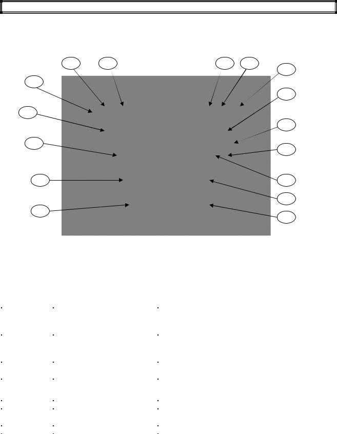
MACHINE KEYPAD
16 |
15 |
14 |
13 |
|
|
|
12 |
11 |
|
|
|
|
|
|
2 |
1 |
|
DISPLAY |
|
|
|
|
|
|
|
|
10 |
3 |
|
|
9 |
|
|
|
|
5 |
|
|
4 |
|
|
|
6 |
7
8
|
|
|
KEY |
PLUS 10 |
|
|
PLUS 10 |
PLUS 10 |
PLUS 10 |
|
|
|
REFERENCE |
LM |
|
|
COF |
SELF LM |
SELF COF |
|
COFFEE GROUP |
|
1 |
Espresso |
|
1 |
Espresso |
Espresso |
Espresso |
|
|
|
2 |
Espresso Macchiato |
2 |
Espresso |
Espresso Macchiato |
Coffee |
|
|
|
|
3 |
Coffee |
1 |
Coffee |
DISABLE |
DISABLE |
|
|
|
|
4 |
Cappuccino |
2 |
Coffee |
DISABLE |
DISABLE |
|
|
|
|
5 |
Large coffee |
|
1 |
Black Coffee |
Large coffee |
Large coffee |
|
|
|
6 |
Latte macchiato |
2 |
Black coffee |
Latte macchiato |
Black coffee |
|
|
|
|
7 |
Caffè Latte |
1 |
Americano |
DISABLE |
DISABLE |
|
|
|
|
8 |
Milk |
|
1 Jug |
DISABLE |
DISABLE |
|
|
|
|
9 |
Hot water |
|
Hot water |
Hot water |
Hot water |
|
|
|
|
10 |
Steam |
|
Steam |
Milk |
Americano |
|
|
SERVICES |
|
11 |
On-Off |
|
On-Off |
On-Off |
On-Off |
|
|
|
|
12 |
Clean / Shift / |
|
Clean / Shift / |
Clean / Shift |
Clean / Shift |
|
|
|
|
|
Continuos / Enter |
|
|
Continuos / Enter |
|
|
|
|
|
13 |
+ |
|
+ |
|
+ |
+ |
|
|
|
14 |
- |
|
- |
|
- |
- |
|
|
|
15 |
Scroll |
|
Scroll |
Scroll |
Scroll |
|
|
|
|
16 |
Esc |
|
Esc |
Esc |
Esc |
|
|
|
|
|
|
|
|
|
|
|
Page 5 of 62
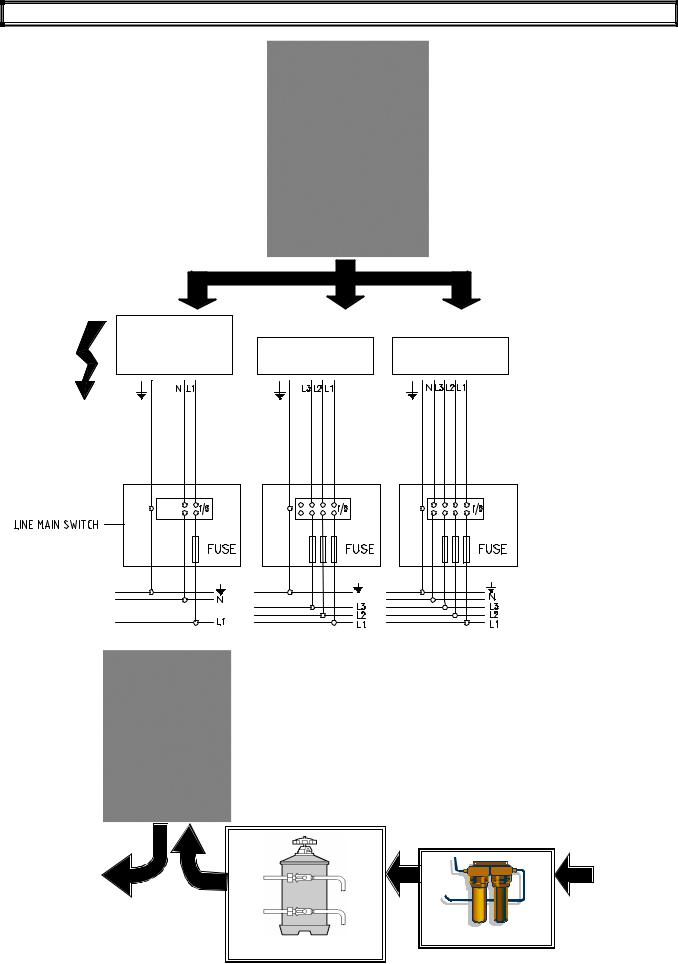
ELECTRIC CONNECTION
120V-1+N-50/60HZ
200V-1+N-50/60HZ |
200V-3 -50/60HZ |
400V-3+N-50/60HZ |
230V-1+N-50/60HZ 230V-3 -50/60HZ
|
|
H2O IN |
H2O OUT |
|
|
|
(1-5 Bar) |
|
|
|
|
|
|
|
WATER FILTRE
WATER SOFTNER
Page 6 of 62
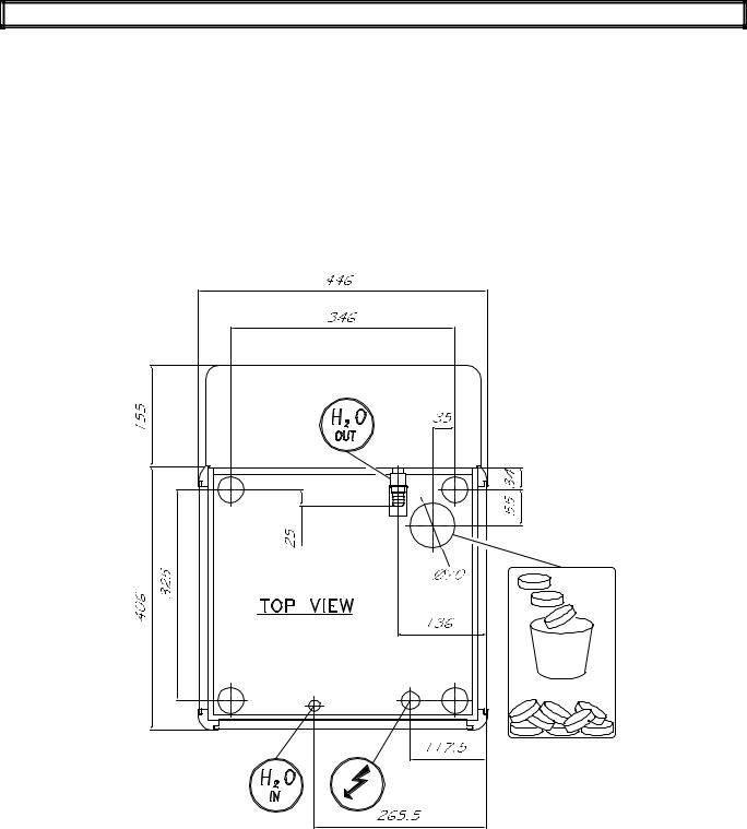
POSITION FOR ELECTRICAL – HYDRAYLIC CONNECTION AND DIRECT DISCHARGE
Page 7 of 62
STARTING UP
Please note :
For machines with modem/gsm , disconnect the power supplier before switch on the coffee machine. Only after insert the Remote control setting connect the modem/gsm power supplier.
Press ON/OFF key to switch the machine ON
La San Marco
ZZZZ ZZZ ZZZ
Rev. X.XXX
Enter
After a few seconds The display shows
Language
English
Enter
La San Marco:
 ZZZZ ZZZ ZZZ Indicate the installation date Rev.X.XXX : Indicate the Software release inserted
Use:
+/- : to select the language
Serial Number
000000
Enter
Installation date
--/ -- / ----
Enter
Installation date -- / -- / ----
Please confirm
Enter
OFF
Insert the Machine serial Number Use: +/- Keys to select the number  Press Enter to confirm the number
Insert the Installation Date
Use + / - Keys to select numbers
Press Enter to confirm the numbers
In case of wong data
Inserted please switch the machine
Off before confirm
WARNING:
If the language choice is not displayed keep the machine in OFF mode. It is absolutely necessary contact your technical service to carry out a PRESET CONFIGURATION DATA procedure .
Page 8 of 62

Press the key N°11( ON/OFF ), the display shows:
Filling - up steam boiler
During this stage the steam boiler is being filled up.
WARNING
In according to the machine configuration in this stage will be release the air inside the boiler by opening a steam nozzle, milker or hot water solenoid valve.
When the steam boiler has been filled up,the display shows:
Filling - up coffee boiler
Press T 1
When water exits
During this stage the coffee boiler is being filled up
WARNING:
The upper piston of the coffee group positions itself inside the brewing chamber, and the coffee boiler starts filling up. When the coffee spout starts dispensing water, press the key dose N° 1 to confirm that the filling up procedure has been carried out. When the coffee boiler has been filled up, the display shows:
Coffee  Steam
Steam
XXX C°  YYY C°
Where:
-XXX °C indicates the temperature of the coffee boiler
-YYY ° C indicates the temperature of the steam boiler
WARNING:
A)DURING THIS STAGE REMOVE ANY PITCHER WITH MILK OR ANY OTHER KIND OF LIQUID BY THE STEAM WAND.
B)DURING THIS STAGE THE STEAM NOZZLE SOLENOID VALVE FOR PLUS 10 COF VERSION AND THE MILK FROTHER SOLENOID VALVE FOR PLUS 10 LM WILL STAY OPEN UNTIL 95°C. THIS WILL RELEASE THE AIR FROM THE BOILER AND GENERATE STEAM.
c) WHEN THE BOILER TEMPERATURE OF 50°C ITS REACHED THE MACHINE CARRY-OUT A RINSING GROUP .THIS IS USEFULL TO RELEASE AIR FROM THE WATER COFFEE CIRCUIT;
The Display shows:
G.Auto cleaning
When the set-up temperature has been reached,
For machine configurations: Standard.
The display shows:
Select drink
For machine configurations: Self.
The display shows:
Select drink |
Position the cup |
Alternated with the message:
Page 9 of 62

For machine configurations: waiters’ card
The display shows:
Insert card
For machine configurations: Self +Credit card
The display shows:
Insert card
For machine configuration: Self with coin box
The display shows:
Select Drink
For machine configuration: Self with coin box + credit card.
The display shows:
Select Drink
WARNING:
For Self with coin box configuration the selections doses are enabled only when the set-up temperature of both boilers ( CoffeeSteam ) have been reached.
To switch ON/OFF the machine on every type of Self – configuration keep pressed for 5 sec. Key N° 11 (ON/OFF)
To turn the machine OFF, open the machine front door or insert the smart card and press the key N°11 (ON/OFF), or use the main external switch (see diagram).
In case of temporary voltage drop, the machine will be automatically turned back to the stage previous to the voltage drop.
If the display shows:
SELECT DRINK
Coffee not ready
The displayed message indicates that the set up heating temperature in the coffee boiler has not been reached yet, and therefore coffee based dispensing are not enabled
If the display shows:
SELECT DRINK
Steam not ready
The displayed message indicates that the set up heating temperature in the steam boiler has not been reached yet, and therefore milk based dispensing and hot water and steam dispensing are not enabled.
In both cases wait until the boiler has reached the set up heating temperature.
Page 10 of 62
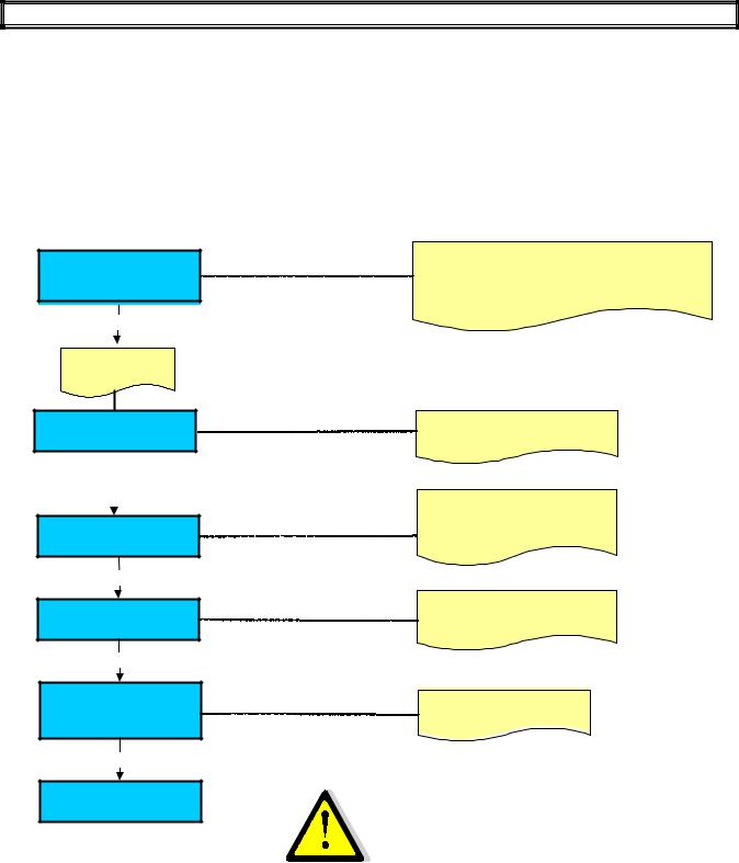
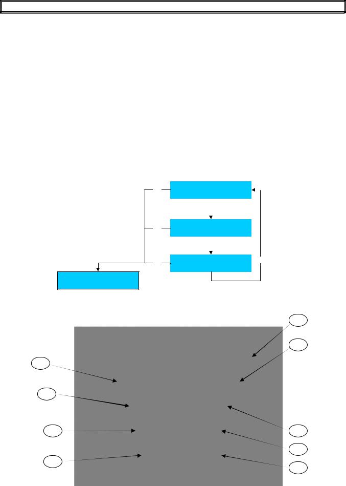
SCHEMATIC SUMMARY OF STEAM BOILER HEATING PHASE
|
Heating element On |
30” Pause |
|
|
Temperature sensor |
( Please Wait ) |
|
Heating element Off |
|
ON |
|
|
|
|
|
|
( Select Drink ) |
|
|
OFF |
|
110°C |
123 °C |
°C |
0 °C |
|
|||
Steam nozzle |
|
|
|
|
solenoid valve |
Solenoid valve open |
|
|
|
ON |
|
|
|
|
OFF |
|
|
Solenoid valve close |
°C |
0 °C |
|
95°C |
|
|
|
|
|
||
Milk frother |
|
|
|
|
solenoid valve |
Solenoid valve open |
|
|
|
ON |
|
|
|
|
OFF |
|
|
Solenoid valve close |
°C |
0 °C |
|
95°C |
|
|
Coffee group |
|
|
|
|
solenoid valve |
Rinsing phase |
|
|
|
ON |
50°C |
|
|
°C |
OFF |
|
|
|
|
Page 11 of 62
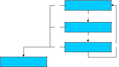
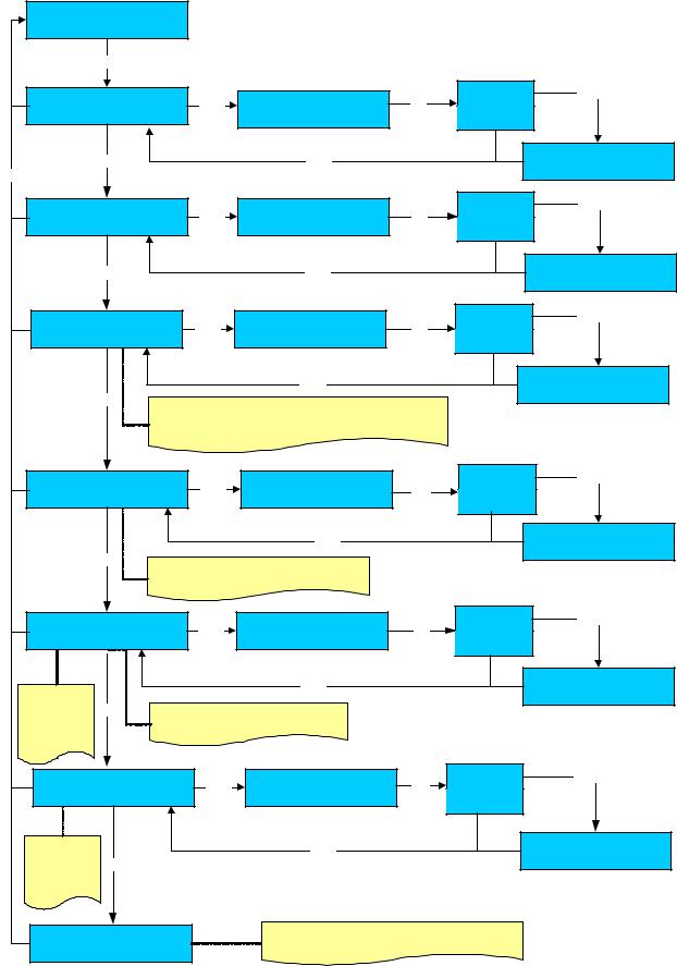
ACCESS THE MAIN SETTING MENUS WITH PASSWORD OR SMART-CARD
A) ACCESS THE MAIN SETTING MENUS WITH PASSWORD
To enter the programming environments, a password is required which define the access rights to the different environments.
The password must be composed with 5 numbers.
To insert the passwords proceed as follows:
-Turn the machine OFF
-Keep N°12 “Enter” key pressed and at the same time turn on he machine. The display shows:
|
|
|
Password |
|
|
|
|
- - - - - |
|
Enter one of the following passwords: |
||||
- |
Waiter |
_ _ _ _ _ ( _ = Clean / Enter ) |
||
- |
Roaster |
1_ _ _ _ |
|
|
- |
Owner |
2 2 2 2 2 |
|
|
- |
Service |
3 3 3 3 3 |
|
|
- |
Technician |
( for Technician password contact the La San Marco Technical Service ) |
||
After insert the password the display shows the main menu programming environments:
|
Esc |
Select |
|
|
|
|
|
Info - reset |
|
|
|
||
|
|
|
|
|
||
|
|
+ |
/ - |
|
|
|
|
|
|
|
|
|
|
|
|
|
|
|
|
|
|
Esc |
Select |
|
|
|
|
|
Dose programming |
|
|
|
||
|
|
|
|
|
||
|
|
|
|
|
|
|
|
|
+ |
/ - |
|
|
|
|
|
|
|
|
|
|
|
|
|
|
|
|
|
|
Esc |
Select |
+ / - |
|||
|
System manager |
|
|
|
||
|
|
|
|
|
||
|
|
|
|
|
|
|
Off
KEY REFERENCE FOR PASSWORD
0
2
DISPLAY
1
3
5 |
4 |
|
6 |
7
8
Page 12 of 62
B) ACCESS THE MAIN SETTING MENUS WITH SMART CARD
To enter the programming environments , insert one of the following smart cards into the proper slit with the machine in off: :
-WAIETR SMART CARD
-ROASTERSMART CARD
-OWNER SMART CARD
-SERVICE SMART CARD
-TECHNICIAN SMART CARD
Press the n°12 key, the display shows:
Esc
Esc
Esc
Select |
|
Info - reset |
|
+ / - |
|
Select |
|
Dose programming |
|
+ / - |
|
Select |
+ / - |
System manager |
|
Off
WARNING:
a)After insert the card, wait at least 2 seconds before removing the card from its proper slit; during this time the display shows a card icon. If the card is removed during this stage, the card might suffer irreparable damages.
b)If you use a card having a card code different from the machine code, the card can no longer be used after two failures.
Page 13 of 62

PROGRAMMABLE PARAMETERS IN ACCORDING WITH PASSWORD OR SMART CARDS
|
|
Password |
Password |
Password |
Password |
Password |
|
|
Smartcard |
Smartcard |
Smartcard |
Smartcard |
Smartcard |
|
|
Technician |
Service |
Owner |
Roaster |
Waiter |
Info - Reset |
Dose Data |
X |
X* |
X |
X* |
X* |
|
System Data |
X |
X |
|
|
|
|
Dose Slight Adj. |
X |
X |
X |
X |
X |
Dose Programming |
Dose Programming |
X |
X |
|
|
|
|
Calibration |
X |
X |
|
|
|
Machine Parameter |
Language |
X |
X |
|
|
|
|
M. Configuration |
X |
|
|
|
|
|
Serial |
X |
X |
X* |
|
|
|
Ground Numbers |
X |
X |
X |
X |
X |
|
Milker |
X |
|
|
|
|
|
Milker Rinsing |
X |
|
|
|
|
|
End Delivery |
X |
|
|
|
|
|
Waiting Time |
X |
|
|
|
|
|
Additional Milk |
X |
|
|
|
|
|
Cold Water Mixer |
X |
|
|
|
|
|
Decimal Price |
X |
|
|
|
|
|
Scale Factor |
X |
|
|
|
|
|
Alarm detail |
X |
|
|
|
|
|
Boiler controller |
X |
|
|
|
|
|
Temperature M.U. |
X |
|
|
|
|
|
Boiler Temperature |
X |
X |
X* |
X* |
X* |
|
Display Temperature |
X |
X |
X |
|
|
|
Steam Nozzle |
X |
|
|
|
|
|
Installation date |
X |
|
|
|
|
System Clock set up |
System Clock |
X |
X |
|
|
|
|
YY-MM-DD Day HH:MM |
X |
X |
X* |
X* |
X* |
|
Clock Display |
X |
X |
X |
|
|
|
Auto Start-up |
X |
X |
X |
|
|
|
ON - OFF |
X |
X |
X |
|
|
|
Day Off |
X |
X |
X |
|
|
Service - Clean/ Rinse |
Cleaning time |
X |
X |
X |
X |
X |
|
Group Cleaning |
X |
|
|
|
|
|
Group Rinsing |
X |
X |
X |
X |
X |
|
Milker Cleaning |
X |
|
|
|
|
|
Milker Rinsing |
X |
X |
X |
X |
|
|
Installation date |
X |
X |
|
|
|
Maintenance Set up |
Water Filter |
X |
X |
|
|
|
|
Machine Service |
X |
X |
|
|
|
|
Grinder Cycle |
X |
X |
|
|
|
|
Group Cycle |
X |
X |
|
|
|
Change Password |
Technician |
X |
|
|
|
|
|
Service |
X |
X |
|
|
|
|
Owner |
X |
X |
X |
|
|
|
Roaster |
X |
X |
X |
X |
|
|
Waiter |
X |
|
|
|
|
Set-Up Encoder |
M.H. M.E. M.L. |
X |
X |
|
|
|
|
Max High Motor Pulse |
X |
|
|
|
|
|
H.M. Stand by Pos Puls |
X |
|
|
|
|
|
H.M. Deliv. Pos Puls |
X |
|
|
|
|
|
Max Low Mot. Puls |
X |
|
|
|
|
|
L.M.Expell Pos Puls |
X |
|
|
|
|
|
L.M. Grind Pos Puls |
X |
|
|
|
|
Test Actuators |
Test Actuators 1 |
X |
X |
|
|
|
|
Test Actuators 2 |
X |
X |
|
|
|
Boiler Draining |
Boiler Draining |
X |
X |
|
|
|
Alarm History |
Alarm History |
X |
X |
X* |
X* |
X* |
File Manager |
Download |
X |
|
|
|
|
|
Load |
X |
|
|
|
|
Update Software |
Download |
X |
|
|
|
|
|
Load |
X |
|
|
|
|
Preset Config. Data Preset Configuration Data |
X |
X |
|
|
|
|
Where X indicate the available program and X* indicate the partial available program
N.B.:
A)The System Clock set up is available only with the optional clock and if the System Clock is set in ON position by the Technician
B)If the “PRESET CONFIGURATION DATA” is done with the Service smart card or password will be reseted only the service accessible parameters.
Page 14 of 62
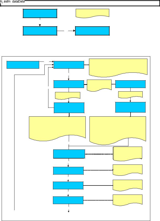
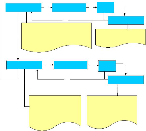
INFO-RESET
A) READ DOSES DATA
Info reset Read Doses Data
Enter |
Read Doses Data |
|||
|
||||
|
|
x |
|
|
|
|
Enter |
|
|
|
Read doses Data |
|||
|
Select button |
|
||
Esc |
|
|
|
|
Select a button between |
||||
|
T1 to T 10 |
|
|
|
|
Read doses Data |
|||
|
TX |
XXXXXX |
||
N° |
0- -i |
0 |
|
|
Press the + / - keys to select the count A or B.
Is possible read two counter A or B, which can be use one for the total number of the dispensed daily doses and another for the total number of the dispensed weekly or monthly doses .
Press twice the dose |
Read doses Data |
|
|
button to read the |
|
||
Select button |
|
||
SHIFT count |
|||
|
|
||
|
Select a button |
|
|
|
between T1 to T 10 |
||
Read doses Data TX XXXXXX
N° 0 - - i 0
TX Indicates the number of the key
XXXXX Indicates the name of the selected button N° 0 Indicates the number of cups dispensed
00 Indicates the number of decaffeinated dispensed drink.
Enter
TX |
Indicates the number of the key |
XXXXXIndicates the name of the SHIFT selected button
N° 0 Indicates the number of the SHIFT cups dispensed
00 Indicates the number of the SHIFT decaffeinated dispensed drink.
Total Dose
Total Dose Y
X
X
Enter
Extra milk
X
Enter
Group cleaning
X
Enter
Milker cleaning
X
Y: X:Indicatesthethecoutertotal doseA o B
Xdelivered: Indicatesfromthecountertotal dose
A or B delivered
X : Indicates the n° of Extra milk carried out
X : Indicates the n° of Group cleaning carried out
X : Indicates the n° of Milker cleaning carried out
Enter
Page 15 of 62
Displayed only with Self + coin box configuration
Enter
Total cashing x.xx
Enter
Total token cashing x.xx
Enter
Token A : |
XX |
Token B : |
XX |
Token C : |
XX |
Enter
Reset Doses Counter
+ / -
X
X.XX: Indicates the total cashing of the machine.
The total will be calculates if the selling price has been set for each dose.
X.XX: Indicates the total token cashing of the machine.
The total token will be calculates if the selling price of the token has been set for each dose.
XX : Indicates the n° of the token A-B-C inserted.
Press the + / - keys to select the count A or B.
Enter |
|
Enter |
|
|
|
Reset Doses Counter |
+ / - |
No |
Please confirm |
||
|
|
Yes |
WITH THIS OPERATION WE RESET ONLY THE DOSES COUNT – EXTRA MILK AND TOTAL CASHING
Enter
Reset Doses Counter
Page 16 of 62
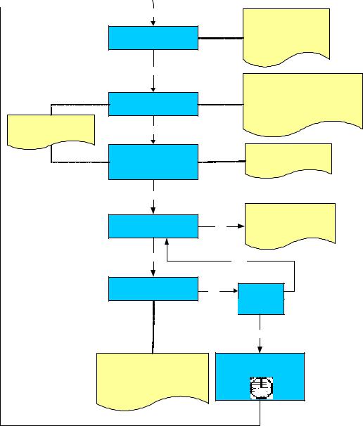
B) INFO RESET SYSTEM DATA |
|
|
|
|
||
Info Reset |
|
|
|
|
|
|
System data |
|
|
|
|
|
|
Enter |
|
|
|
|
|
|
Group cleaning |
XX |
|
Group cleaning |
Yes |
Enter |
|
Enter |
+/ - |
|
|
|||
|
|
|
Confirm reset |
No |
|
|
+ |
|
|
Enter |
|
Group cleaning |
0 |
Esc |
|
|
|
|
|
|
Milker cleaning |
XX |
|
Milker cleaning |
Yes |
Enter |
|
Enter |
+/ - |
|
|
|||
Confirm reset |
|
|
||||
|
|
|
No |
|
|
|
|
|
|
|
|
|
|
+ |
|
|
Enter |
|
Milker cleaning |
0 |
Grinder Cycles |
XX |
|
Grinder Cycles |
Yes |
Enter |
|
Enter |
+/ - |
|
|
|||
Confirm reset |
|
|
||||
|
|
|
No |
|
|
|
|
|
|
|
|
|
|
|
|
|
Enter |
|
Grinder Cycles |
0 |
+If the Machine Service has been set on the display will
show only the total n° grinder cycles but not the relative alarm
Water filter |
XX |
Enter |
Water filter |
Yes |
Enter |
|
||
+ / - |
|
|
||||||
Confirm reset |
|
|
||||||
|
|
|
|
|
|
|
||
|
|
|
|
|
|
No |
|
|
|
|
|
|
|
Enter |
|
Water filter |
0 |
|
+ |
|
Displayed only if |
the Service frequency for |
|
|
|
|
|
|
|
|
|
|
|||
|
|
|
|
water filter has been set off |
|
|
|
|
Group cycles |
XX |
|
Group cycles |
Yes |
Enter |
|
||
Enter |
+/ - |
|
|
|||||
Confirm reset |
|
|
||||||
|
|
|
|
|
No |
|
|
|
|
|
|
|
|
|
|
|
|
It indicates |
|
|
|
|
Enter |
|
Group cycles |
0 |
|
|
|
|
|
|
|
|
|
the N° of |
+ |
|
Displayed only if |
the Machine Service |
|
|
|
|
programmed |
|
|
|
|
||||
|
|
|
parameter has been set off |
|
|
|
||
cycles for |
|
|
|
|
|
|
||
|
|
|
|
|
|
|
|
|
service |
|
|
|
|
|
|
|
|
Total group cycles |
XX |
Enter |
Total group cycles |
Yes |
Enter |
|
||
Confirm reset |
+ / - |
|
|
|||||
|
|
|
|
|
No |
|
|
|
|
|
|
|
|
|
|
|
|
It indicates |
|
|
|
|
Enter |
|
Total group cycles |
|
the N° of total |
|
|
|
|
|
0 |
|
|
+ |
|
|
|
|
|
|
||
cycles of |
|
|
|
|
|
|
|
|
|
|
|
|
|
|
|
|
|
group life |
|
|
|
|
|
|
|
|
Tot. Machine Cycles |
XX |
|
It indicates the N° of total cycles of the machine. |
|
|
|||
|
It is not possible to reset the Total machine cycles |
|
|
|||||
Page 17 of 62
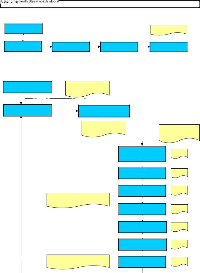
THE FOLLOWING INFO ARE DISPLAYED ONLY WHEN THE CLOCK IS PROGRAMMED
|
|
|
|
|
|
|
|
|
Yes |
|
|
|
|
|
Water filter |
Enter |
|
Water filter |
+ / - |
|
|
Enter |
|||
|
|
|
|
|
|
|
|
|||||
|
|
XXXX |
YY - ZZZZ |
|
Confirm reset |
|
No |
|
|
|
||
|
|
|
|
|
|
|
|
|
||||
|
|
|
|
|
|
|
|
|
|
|
|
|
Enter
XXXX : Indicates the n° of water filter liters left. If the programmed n° of of water filter liters exceed the display shows: ( - XXXX )
YY : Indicates the maintenance month
+ZZZZ : Indicates the maintenace year
If the water filter alarm elapses within one month or if the 90% of the set number of liters has reached, this parameter can be reset
Water filter
XXXXYY - ZZZZ
XXXX: Indicates the n° of water filter liters programmed.
YY : Indicates the next maintenance month ZZZZ : Indicates the next maintenace year
Machine service |
Enter |
Machine service |
Yes |
Enter |
||
XXXX |
YY - ZZZZ |
Confirm reset |
+ / - |
|||
|
|
|||||
|
|
|
|
No |
|
|
|
|
|
Enter |
Machine service |
||
|
|
|
XXXX |
YY - ZZZZ |
||
|
|
|
|
|||
XXXX : Indicates the n° of group cycles left. If the programmed n° of group cycles exceed the display shows: ( - XXXX )
YY : Indicates the maintenance month ZZZZ : Indicates the maintenace year
If the service alarm elapses within one month or if the 90% of the set number of group cycles has reached, this parameter can be reset
XXXX : Indicates the n° of group cycles programmed.
YY : Indicates the next maintenance month ZZZZ : Indicates the next maintenace year
N.B.: WITH THE MACHINE SERVICE RESET WILL BE ERASE ALSO THE CLEANING GROUP AND MILKER TOTAL NUMBER.
WARNING:
The owner’s card can only enter total dose reset environment and water softener alarm reset.
Environments: group cycles, M1 tools time, M2 tools time and water filter litres will be displayed only if values higher than 000 (zero) have been set during the programming stage.
Page 18 of 62
DOSES PROGRAMMING
PLEASE NOTE : TO ACCESS TO THE DOSES PROGRAMMING THE MACHINE MUST BE AT THE SET-UP TEMPERATURE.
A ) DOSES SLIGHT ADIUSTMENT
Page 19 of 62
 Loading...