

LAARS TL00-199 User Manual
Installation, Operation and Maintenance Instructions Document 2118A
Installation,
Operation and
Maintenance
Instructions for
™
Mighty-Stack
Gas-Fired
Water Heater
Model TL00-199
These instructions are to be stored next to the water heater for reference purposes.
FOR YOUR SAFETY: This product must be installed and serviced by a professional service technician,
qualified in hot water heater installation and maintenance. Improper installation and/or operation could
create carbon monoxide gas in flue gases which could cause serious injury, property damage, or death.
Improper installation and/or operation will void the warranty.
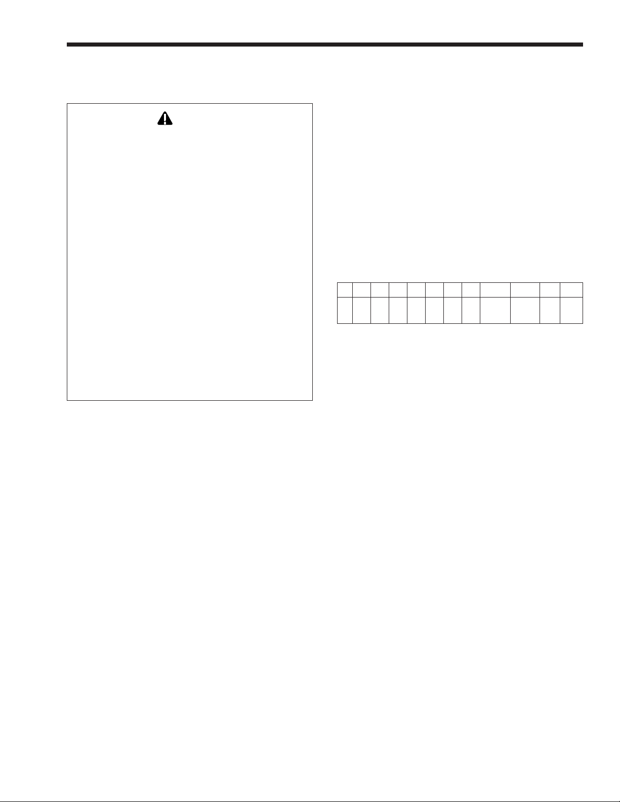
WARNING
If the information in this manual is not followed exactly, a fire or explosion may result
causing property damage, personal injury or loss of life.
Do not store or use gasoline or other flammable vapors and liquids in the vicinity of this or
any other appliance.
WHAT TO DO IF YOU SMELL GAS
• Do not try to light any appliance.
• Do not touch any electrical switch; do not use any phone in your building.
• Immediately call your gas supplier from a nearby phone. Follow the gas supplier's
instructions.
• If you cannot reach your gas supplier, call the fire department.
Installation and service must be performed by a qualified installer, service agency, or gas
supplier.
H2206000A
A subsidiary of BRADFORD WHITE Corporation

Page 2
LAARS HEATING SYSTEMS
TABLE OF CONTENTS
SECTION 1.
General Information
1A. Introduction...................................................3
1B. Warranty Information....................................3
1C. Unpacking ....................................................3
1D. Heater Identification ..................................... 3
1E. Dimensions...................................................3
1F. Identifying Important Components................ 3
1G. Placing the Water Heater ............................. 3
1H. Gas Supply Piping ........................................ 5
1I. Combustion Air Supply.................................6
1J. General Venting Instructions ........................7
1K. Vertical Venting — Category I ...................... 7
1L. Horizontal Venting — Category III................8
1M. Water Piping................................................. 9
1N. Electrical Wiring..........................................10
1P. Filling the Contractor Supplied
Storage Water Tank ................................... 11
1Q. Water Condition and Pump
Requirements ............................................. 11
SECTION 2.
Operating Instructions
2A. Starting the System ....................................14
2B. Starting the System After
Extended Shut-Down .................................15
2C. Shut-Down Procedure ................................ 15
2D. Extended Shut-Down —
Cold Weather Areas ................................... 15
SECTION 3.
Maintenance and Service
3A. Regular Maintenance ................................. 17
3B. Recommended Annual Inspection ............. 17
3C. Cleaning the Heat Exchanger ....................17
3D. Operating Sequence .................................. 17
3E. Cleaning the Pilot and Main Burners .......... 18
3F. Electrical Troubleshooting .......................... 19
3G. Parts Listing................................................21
Mighty Stack Water Heater
Page 3
SECTION 1.
General Information
WARNING
To install this unit correctly, you
procedures listed in this manual. If you do not do
this, the warranty offered by Laars will be voided.
Follow the requirements of the local jurisdiction
which has authority over the installation. In the
United States, also follow the latest edition of the
National Fuel Gas Code, ANSI Z223.1/NFPA54.
In Canada, the installation must conform with
the latest edition of CAN/CGA B149.1 or .2
installation codes for gas burning appliances,
and/or local codes.
Where the recommendations made in this
manual are different from the national or local
codes, the national or local codes should take
precedence.
Do not make any changes to the water heater, or
to its gas controls, gas orifices, wiring or draft
inducer. Any modifications may void the warranty. If
the unit must be modified because of special
conditions, talk with a factory representative before
beginning any changes.
1A. Introduction
This manual provides information necessary for
the installation, operation, and maintenance of the
Laars Mighty-Stack Model TL00 water heater. This
unit includes a blower for induced-draft venting, and
has an advanced hot-surface proven-pilot ignition
system.
The model designation is listed on the rating
plate, which is attached to the top of the water heater.
Please read all application and installation
procedures completely before doing the installation. If
you have any problems or questions regarding this
equipment, consult the Laars factory, or local factory
representative. Experience has shown that most
operating problems are caused by improper
installation.
must
follow the
installation date and the name of the installer. Shipping
costs are not included in the warranty coverage.
1C. Unpacking
Some accessory items are shipped in separate
packages. Check to be sure you have received all of
the packages which are listed on the packing slip.
Inspect each item for damage immediately upon
delivery. If there are any shortages or damage, tell the
carrier right away. Any claims should be filed with the
carrier. The carrier, not the shipper, is responsible for
shortages and damage to the shipment whether the
damage is visible or concealed.
1D. Heater Identification
To identify the unit, see the rating plate. Here is
an explanation of the coding system:
12345678 9 101112
TL00–199N or PS,HK X
or I
Table 1. Heater Identification.
1st to 4th characters – series name (TL00)
5th character – dash (–)
6th through 8th characters – input rate (BTU/hr) x 1000
9th character – fuel
N = natural gas
P = propane
10th character - altitude (feet)
S = 0-2000 for natural gas, 0-5000 for propane
H = 2001-5000 for natural gas
I = 5001-10,000 for natural gas and propane
11th character - Heat Exchanger Type
K = Copper
12th character - X
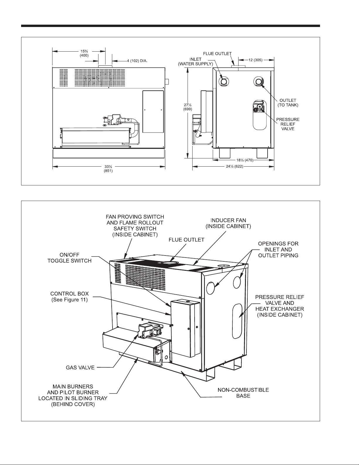
1E. Dimensions
Figure 1 shows the dimensions of this unit.
1F. Identifying Important Components
Figure 2 shows the switches and sensors on
this unit.
1B. Warranty Information
The Laars Mighty-Stack Model TL00 water
heater is covered by a limited warranty. A copy of the
warranty is printed on the back cover of this manual.
The owner should fill out the warranty registration
card and return it to Laars.
All warranty claims must be made to an
authorized Laars representative or directly to the
factory. Claims must include the serial number and
model of the unit. (This information is listed on the
rating plate.) The claim must also include the
1G. Placing the Water Heater
This water heater is designed for indoor use
only. The enclosure is not designed for outdoor
installation.
1. Choose a convenient indoor location. Be sure
that any leaking water from the connections will
not damage the area near the appliance. If the
unit must be installed on an upper floor of a
multistory structure, ensure that any leaking
water will not damage areas below the appliance.
If a suitable location can not be found, install a
Page 4
LAARS HEATING SYSTEMS
Dimensions shown in inches (mm)
Figure 1. Dimensions.
Figure 2. Component Locations.
Mighty Stack Water Heater
drain pan under the appliance. Make sure the
drain pan is properly piped to an adequate drain.
2. Place the water heater as close as possible to the
vent or chimney.
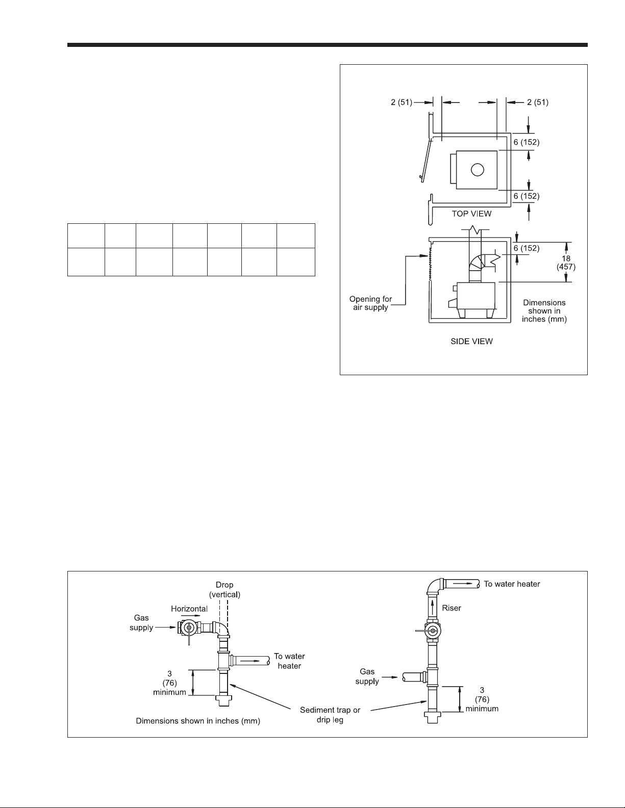
3. For minimum clearances around the water heater,
refer to Table 2. Maintain the minimum distances
from all combustible surfaces (see Figure 3). The
unit can be installed in a closet. Pay special
attention to the air supply opening to the closet.
It is recommended that at least 12 inches
(305mm) is allowed around the entire unit for
maintenance, inspection, and plumbing access.
Left Right
Side Side Rear Front Flue* Top
inches 6 6 2 2 6 18
mm 152 152 51 51 152 457
*One inch (25 mm) clearance using type B double wall vent pipe
when vented vertically.
Table 2. Minimum Clearances from
Combustible Surfaces.
Page 5
4. This product may be installed on combustible
flooring. Do not install directly on carpeting.
5. Be sure that the parts in the gas ignition system
are protected from water when the water heater is
operating or being served. Arrange water lines in
the area so that water cannot drip or spray onto
the water heater.
1H. Gas Supply Piping
Please review these instructions before installing
the water heater.
1. Check that the water heater is fitted for the
proper type of gas by checking the rating plate.
2. Laars water heaters are normally equipped to
operate below a 2000 foot altitude. Water heaters
Figure 3. Installation in Closet.
equipped to operate at higher altitudes have
appropriate information on the rating plate.
3. Use the figures in Table 3 to provide adequate
gas piping from the gas meter to the water heater.
4. A sediment trap (drip leg) must be provided
ahead of the gas controls (see Figure 4). A
manual gas shutoff valve must also be provided
for service, convenience and safety. This should
be installed about 5 feet (1.5 m) above the floor.
Check the local codes.
Figure 4. Gas Supply Piping.
Page 6
LAARS HEATING SYSTEMS
5. Turn off the water heater before you do any
pressure testing on the gas lines.
If you will be testing at a pressure greater than
1/2" psig (3.5 kPa) –
Disconnect the gas line before the water heater
and before the shutoff valve for the water heater.
If you will be testing at a pressure equal to or
less than 1/2" psig (3.5 kPa) –
Turn off the manual shut off valve ahead of the
water heater gas controls.
6. Provide gas to the water heater at the pressure
shown in Table 4. The regulator is preset at the
factory, and normally requires no further
adjustment.
Distance from Gas Meter Pipe Size
0' – 200'
NOTE: These figures are for Natural Gas (.65 Sp. Gr.), and are
based on 1/2" water column pressure drop. Check supply
pressure with a manometer, and local code requirements for variations. For LPG, reduce pipe diameter one size,
but maintain a 1/2" minimum diameter. A “normal” number of
Tees and elbows have been taken into allowance.
Minimum Supply
Maximum Supply
Manifold Gas
* Listed for purposes of inlet adjustment.
** The gas supply should not exceed this pressure.
0 – 60 m
Table 3. Gas Piping Size.
Water Column
Natural Gas Propane (LP)
i.w.c.
Pressure*
Pressure**
Pressure
Table 4. Gas Pressure Measurement.
10
kPa
1.5
6
2.5
1.0
4
1¼"
i.w.c.
11
14
9
kPa
2.7
3.4
2.2
Note: When measuring the inlet supply pressure, the
water heater and all other gas appliances sharing the
water heater gas supply line must be firing at
maximum capacity. Low gas pressure could be
caused by an undersized gas meter or an obstructed
gas supply line.
7. Before operating the water heater, the complete
gas supply system and all connections must be
tested for leaks using a soap solution.
Caution
Some solutions used for leak testing may cause
corrosion or stress cracking. (These include soap
and water.) To prevent this, rinse the piping with
water after testing.
1I. Combustion Air Supply
The water heater location must provide enough
air for proper combustion and ventilation of the
surrounding area. See the latest edition of ANSI
standard Z233.1 or in Canada, CAN/CGA-B149.1 or
.2, and any local codes that may be applicable.
In general, these requirements specify that if the
unit is installed in a confined space, there must be at
least two permanent air supply openings. One opening
should be within 12 inches (305mm) of the ceiling,
and the other should be within 12 inches (305mm) of
the floor.
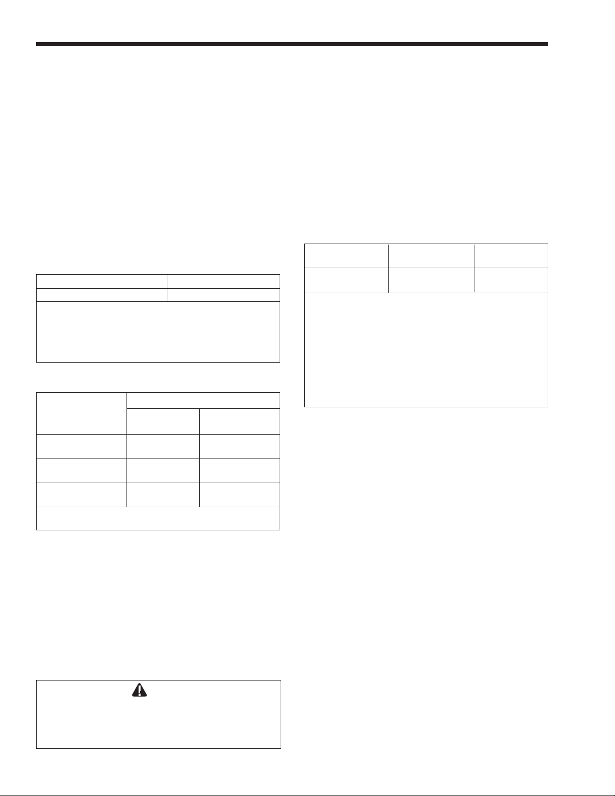
For installation in U.S.A.:
Water Heater Outside Air Inside Air
Size Area
199 50 sq in 199 sq in
323 sq cm 1284 sq cm
The area indicated is for one of two openings; one at floor
level and one at ceiling, so the total net free area would be
double the figures indicated. For special conditions, refer
to NFPA54 ANSI Z223.1.
†
Outside air supply – Combustion air is supplied directly
through an outside wall.
††
Inside air supply – Combustion air is supplied from inside
the building.
NOTE: Check with louver manufacturers for Net Free Area
of Louvers. Correct for screen resistance to the New Free
Area if a screen is used.
Table 5. Minimum Recommended Air Supply
to Water Heater Room.
Outside Air Supply: When combustion air is
supplied directly through an outside wall, each
opening should have a minimum free area of one
square inch per 4,000 BTUH input of the total input
rating of all appliances in the enclosed area.
Inside Air Supply: When combustion air is
supplied from inside the building, each opening
should have a minimum free area of one square inch
(6.5 sq cm) per 1,000 BTUH input of the total input
rating of all appliances in the enclosed area. These
openings should never be less than 100 square inches
(645 sq cm).
For installation in Canada:
NOTE: In Canada, follow Canadian Standard
CAN/CGA-B149 or local codes.
Exhaust Fans or Vents: Any equipment which
exhausts air from the room around the unit can deplete
the combustion air supply. Such equipment can also
reverse the action of the venting system. This could
cause flue products to accumulate in the space where
the water heater is installed. Additional air must be
supplied to compensate for any exhaust effect.
†
Area
††
Mighty Stack Water Heater
Page 7
The information in Table 5 is not applicable in
installations where exhaust fans or blowers of any
type are used. Such installations must be designed by
qualified engineers.
If a blower or fan is used to supply air to the
water heater room, the installer should make sure it
does not create drafts which could cause nuisance
shutdowns. If a blower is necessary to provide
adequate combustion air to the water heater, a switch
or equivalent must be wired into the water heater
control circuit to prevent the water heater from firing
unless the blower is operating.
The water heater must be protected from any
source of corrosive chemical fumes including those
emitted by trichlorethylene, perchlorethylene,
chlorine, etc.
1J. General Venting Instructions
WARNING
This water heater must be vented in accordance
with Part 7, Venting of Equipment, of the latest
edition of the National Fuel Gas code, ANSI Z223.1
and all applicable local building codes. In Canada,
follow CAN/CGA B149 Installation codes. Improper
venting of this appliance can result in excessive
levels of carbon monoxide which can result in
severe personal injury or death!
Here are some general rules to follow when
venting this unit:
• Place the water heater as close as possible to the
vent or chimney.
• The vent collar on the water heater must be
fastened directly to an unobstructed vent pipe.
Use rustproof sheet metal screws no longer than
1/2" (13 mm).
• Do not weld the vent pipe to the water heater
collar. The weight of the stack must not rest on
the water heater. The top of the water heater
must be easily removable for normal service and
inspection of the unit.
• Avoid using an oversized vent pipe or using
extremely long runs of the pipe. This may cause
excessive cooling and condensation of flue gases.
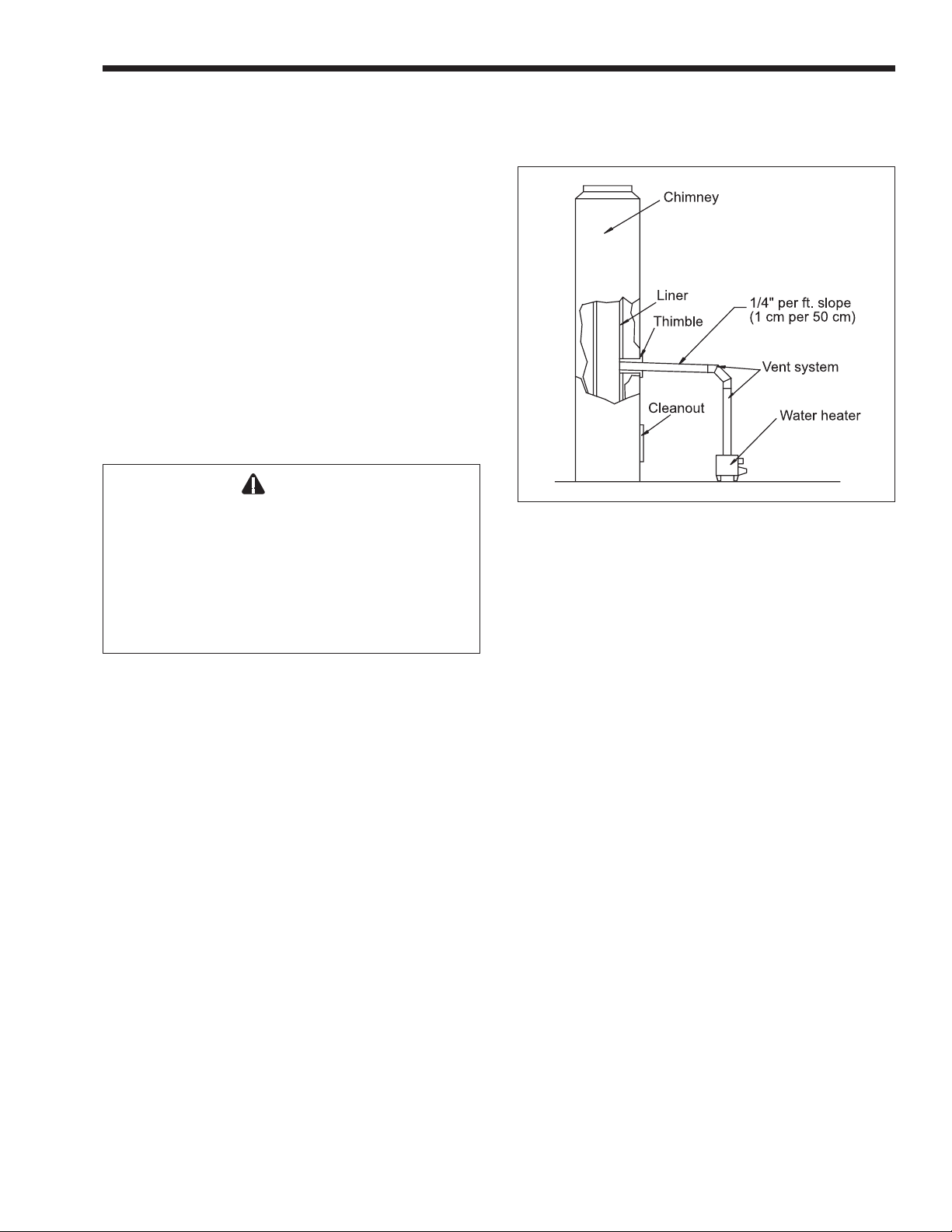
Figure 5. Chimney Venting.
1K. Vertical Venting – Category I
This unit can be vented into a masonry chimney,
provided several conditions are met (see Figure 5.)
• The chimney must have an appropriate tile
lining. The lining should be the correct size,
should be constructed correctly, and must be
clean.
• Check the chimney passage way to be sure that it
is clear and free of obstructions.
• If the chimney must be rebuilt, follow nationallyrecognized standards. (See the National Building
Code or ANSI/NFPA 211).
• When the water heater and a boiler are to be
connected to the same chimney, each unit must
have its own vent connector. The two connectors
must enter the chimney at least 6" (152 mm)
apart.
• The water heater vent must not be connected to a
fireplace, wood stove or other equipment which
burns solid fuel.
• Avoid terminating the water heater vent near any
air-conditioning or air-supply fans. These fans
can pick up the exhaust flue products from the
water heater and return them to the building.
This can create a health hazard.
(a) Vent Connections
Use type B double wall or type C single wall gas
vent pipe (26 gauge, minimum thickness) from the
water heater to the chimney. Laars recommends
installation of a riser with a minimum of 12" (305
mm) height above the water heater. The vent system
should be sloped up toward the chimney at a rate of 1/
4" per foot (1 mm per 50 mm). The vent connector
must be strong enough to support the weight of the
Page 8
LAARS HEATING SYSTEMS
material used. This will maintain the clearances and
prevent physical damage and separation of the joints.
NOTE: Always provide a minimum clearance of
6 inches between a Type C vent pipe and any
combustible materials.
Warning
Single-wall vent pipe must
interior walls, or through floors or ceilings! Failure to
comply with this warning could result in a fire,
causing property damage, personal injury, or death!
never
pass through
When installing the vent system, all applicable
national and local codes must be followed! If you
install thimbles, firestops or other protective devices,
and they penetrate any combustible or noncombustible
construction, be sure to follow all applicable national
and local codes.
If a vertical vent is installed, follow the code
requirements for Category 1, Fan Assisted Appliances.
Follow the requirements as indicated in the latest
edition of ANSI Z223.1/NFPA 54. See “Sizing of
Category I Venting Systems” and “Appendix G.” In
Canada, follow the instructions in the CAN/CGAB149 installation code.
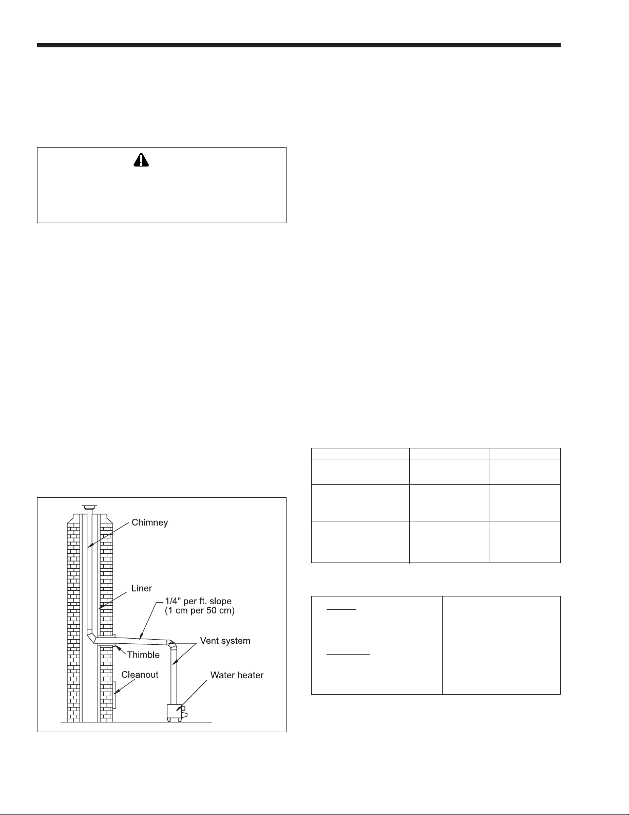
An unused chimney can be used as a raceway for
a single-wall vent pipe. (See Figure 6). Never run a
vent pipe through a flue that has another appliance
attached to it.
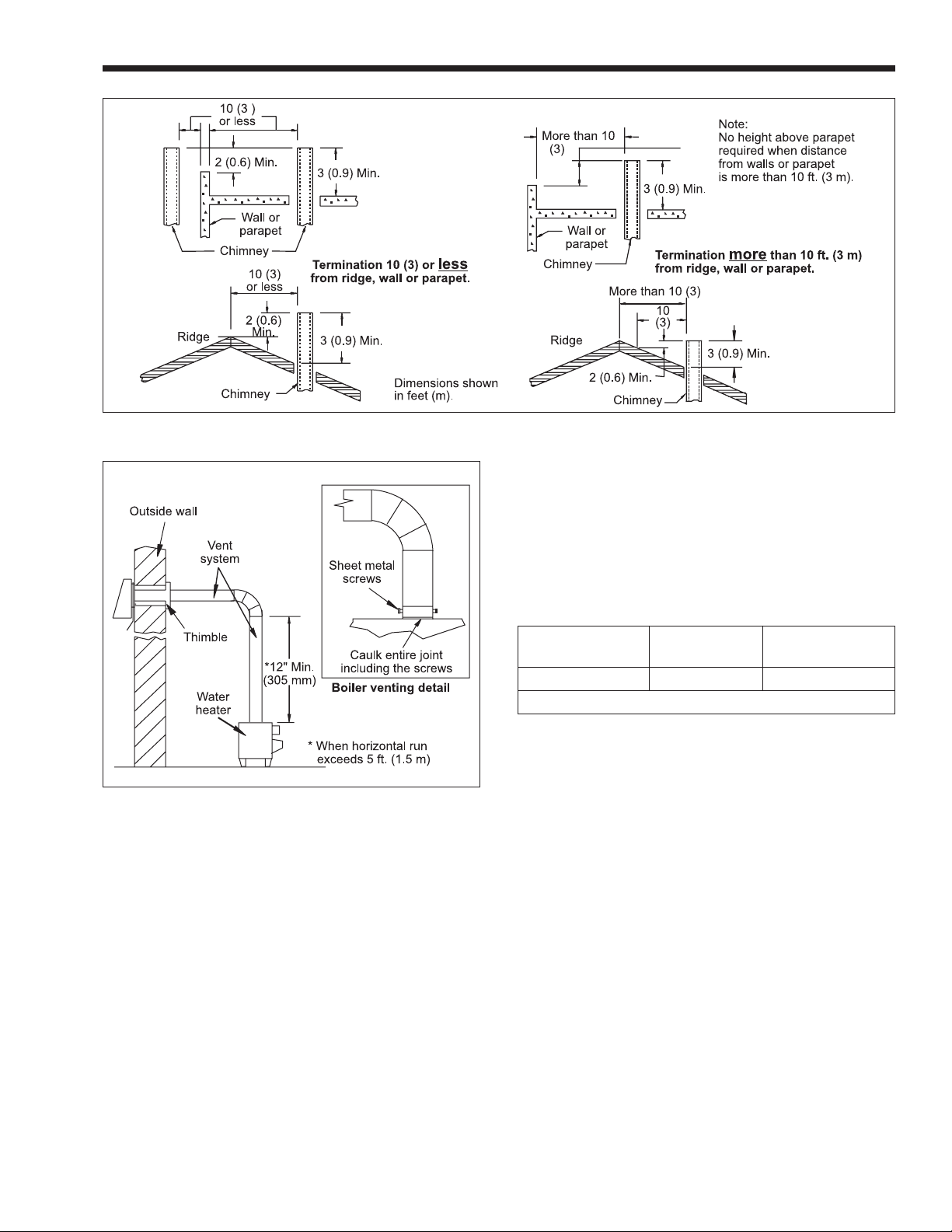
(b) Vent Termination
A listed vent terminal must complete the vertical
run where it exits the chimney. This must be designed
for the type of pipe being used. The vent pipe must
extend at least 3 feet (1 m) above the highest point
where it passes through the roof. In addition, the vent
cap must be at least 2 feet (0.6 m) higher than any part
of a building within a horizontal distance of 10 feet (3
m). Clearance to any combustible materials must be
maintained as listed. (See Figure 7).
1L. Horizontal Venting – Category III
When a vent system is horizontal or cannot meet
the requirements of Category I, it can develop positive
pressure. This type of system must be installed in
accordance with the instructions in this section, and
with the instructions supplied by the vent
manufacturer.
(a) Vent connections
The vent system must be gas tight. All seams
and joints must be sealed with silicone sealant or
adhesive tape having a minimum temperature rating of
400°F (204°C). (See Table 6 for a list of approved
sealing materials).
For best results, a horizontal vent system should
be as short and straight as possible. The materials used
in the vent connectors should be as listed in Table 7.
Description Manufacturer Product
High Temperature
RTV Dow Corning Trade Mate
2" (51 mm) wide
aluminum foil tape, Venture Product #3243
backed with adhesive
2" (51 mm) wide
aluminum foil tape 3M Product #433
backed with adhesive
Figure 6. Vertical Venting.
Table 6. Vent Sealing Material.
In USA: Up to a maximum of
Use UL type 304, 316 or 40 feet (12 m) of equiv29-4C stainless steel, alent pipe run (including
26 gauge minimum. required elbows).
In Canada:
Use “BH” vent type
complying with ULC
S-636 Standard.
Table 7. Vent Connector Materials.
Mighty Stack Water Heater
Figure 7. Vertical Vent Termination.
Page 9
• Support the vent run at 3-foot (1 m) intervals
with overhead hangers.
Figure 8. Horizontal Venting.
The water heater vent collar must be fastened to
vent pipe of the same diameter, with rustproof metal
screws no longer than 1/2" (13 mm) and sealed with
high temperature – 500°F (260°C) – silicone sealant.
For larger diameter vent pipes, use a sealed reducer
fastened directly to the water heater collar and seal all
joints as indicated in Figure 8. Allow the sealant to
cure for 24 hours before operating the water heater.
The entire vent system must not exceed the size
specified in Table 8.
The following criteria must be observed:
• Pitch down the vent run, toward the vent
terminal (hood), at a rate of 1/4 inch per foot
(1 cm per 50 cm).
• Do not locate any joint screws at the bottom of
the vent run.
No. of Horizontal Run
Diameter Elbows Length*
102 mm
4"
*For each elbow eliminated, add 5 feet (1.5 m) of allowable vent.
Table 8. Horizontal Venting Configuration.
(b) Vent Termination
4 20'
6 m
A side wall vent terminal (hood) must be used
when the water heater is vented through a side wall.
Use Laars Part Number D2004300, 4" (102 mm) dia.
The vent hood provides a means of installing vent pipe
through the building wall, and must be located in
accordance with ANSI Z223.1/NFPA 54, or in Canada
CAN/CGA-B149 and local applicable codes (see
Figure 9.)
Locate the vent terminal so that it cannot be
blocked by snow. Most codes require that the
termination be at least 12 inches (305 mm) above
grade, but the installer may determine it should be
higher depending on local conditions.
• Attach a vertical pipe at least 12 inches (305
mm) high to the water heater outlet before the
horizontal run if run exceeds 5 feet (1.5m)
(see Figure 8).
1M. Water Piping
1. To prevent damage to the unit, all soldering must
be done before making any connections to the
heater or the tank.
 Loading...