


Installation and Operation Instructions |
Document 1254B |
|
|
Installation and
Operation Instructions for
MINI-THERM
Residential
Gas-Fired
Hydronic Boilers
Models JVH, JVS
|
JVS |
Sizes 50-225 |
|
U.S. Patent No. 1,609,692 |
|
|
|
|
|
|
Canada Patent No. 383,318 |
JVH |
Vent damper is optional in some provinces of Canada.. |
|
These instructions are to be stored next to the boiler for reference purposes.
FOR YOUR SAFETY: This product must be installed and serviced by a professional service technician, qualified in hot water boiler installation and maintenance. Improper installation and/or operation could create carbon monoxide gas in flue gases which could cause serious injury, property damage, or death. Improper installation and/or operation will void the warranty.
 WARNING
If the information in this manual is not followed exactly, a fire or explosion may result causing
property damage, personal injury or loss of life.
Do not store or use gasoline or other flammable vapors and liquids in the vicinity of this or any
other appliance.
WHAT TO DO IF YOU SMELL GAS
•Do not try to light any appliance.
•Do not touch any electrical switch; do not use any phone in your building.
•Immediately call your gas supplier from a nearby phone. Follow the gas supplier's instructions.
•If you cannot reach your gas supplier, call the fire department.
Installation and service must be performed by a qualified installer, service agency, or gas supplier.
H2355800B
 AVERTISSEMENT Assurez-vous de bien suivres les instructions données dans cette notice pour réduire au minimum le risque d’incendie ou d’explosion ou pour éviter tout dommage matériel, toute blessure ou la mort.
Ne pas entreposer ni utiliser d’essence ni d’autres vapeurs ou liquides inflammables dans le voisinage de cet appareil ou de tout autre appareil.
QUE FAIRE SI VOUS SENTEZ UNE ODEUR DE GAZ:
•Ne pas tenter d’allumer d’appareils.
•Ne touchez à aucun interrupteur. Ne pas vous servir des téléphones dansle bâtiment où vous êtes.
•Appelez immédiatement votre fournisseur de gaz depuis un voisin. Suivez les instructions du fournisseur.
•Si vous ne pouvez rejoindre le fournisseur de gaz, appelez le sservice des incendies.
L’installation et l’entretien doivent être assurés par un installateur ou un service d’entretien qualifié ou par le fournisseur de gaz.
Page 2 |
LAARS Heating Systems |
|
|
|
|
TABLE OF CONTENTS
SECTION 1. |
|
|
General Information |
|
|
1A. |
Introduction.................................................... |
3 |
1B. |
Warranty......................................................... |
3 |
1C. |
Heater Identification....................................... |
4 |
SECTION 2. |
|
|
Boiler Assembly & Placement |
|
|
2A. |
Field Assembly............................................... |
4 |
2B. |
Boiler Placement............................................ |
5 |
2C. |
Flooring.......................................................... |
5 |
2D. |
Dimensional Information................................ |
6 |
2E. |
Clearance / Closet Installations...................... |
8 |
SECTION 3. |
|
|
Air and Venting |
|
|
3A. |
Combustion Air Supply................................... |
9 |
3B. |
Venting......................................................... |
10 |
3C. |
Vertical Venting - Category I......................... |
11 |
3D-1 |
Horizontal Venting - Category III.................. |
12 |
3D-2 |
Venting Connections.................................... |
12 |
3D-3 |
Vent Terminations......................................... |
13 |
3E. |
Common Venting System............................. |
13 |
SECTION 4. |
|
|
Gas Connections |
|
|
4A. |
Gas Supply and Piping................................. |
13 |
4B. |
Special Precautions for LP .......................... |
15 |
SECTION 5. |
|
|
Water Connections |
|
|
5A. |
Water Piping................................................. |
15 |
5B. |
By-pass Piping............................................. |
17 |
5C. |
Adjusting the bypass.................................... |
17 |
5D. |
Alternate Auto-Bypass Operation................. |
17 |
5E. |
Flow Requirements...................................... |
18 |
5F. |
Chilled Water Systems................................. |
18 |
5G. |
Oxygen Permeable Systems........................ |
18 |
5H. |
Anti-Freeze................................................... |
18 |
SECTION 6. |
|
|
6A. |
Electrical Wiring........................................... |
20 |
6B. |
Outdoor Reset.............................................. |
20 |
SECTION 7. |
|
|
7A. |
Filling the System......................................... |
25 |
SECTION 8. |
|
|
Operating Procedures |
|
|
8A. |
System Start-up........................................... |
26 |
8B. |
Sequence of Operation................................ |
26 |
8C. |
Operating Instructions, JVH......................... |
27 |
8D. |
Operating Instructions, JVS......................... |
28 |
8E. |
Operating Temperature Control.................... |
29 |
SECTION 9. |
|
|
9A. |
Maintenance................................................. |
31 |
9B. |
Electrical Troubleshooting............................ |
32 |
SECTION 10. Replacement Parts |
|
|
10A. |
Glossary of Terms........................................ |
35 |
10B. |
Parts List JVH.............................................. |
36 |
10C. |
Parts List JVS............................................... |
38 |

Mini-Therm JV |
Page 3 |
|
|
|
|
SECTION 1. General Information
1A. Introduction
This manual provides information necessary for the installation, operation, and maintenance of the Laars Model JV low pressure, copper tube hydronic boilers.
These boilers are available in two configurations; the JVH has a hot surface pilot ignition system and the JVS has an electronic intermittent ignition device (I.I.D.). Look for the model designation on the rating plate, which can be found on top of the boiler.
All application and installation procedures should be reviewed completely before proceeding with the installation. Consult the Laars factory, or local
factory representative, with any problems or questions regarding this equipment. Experience has shown that most operating problems are caused by improper installation.
 WARNING
This hydronic boiler must be installed in accordance with the procedures detailed in this manual, or the Laars warranty will be voided. The installation must conform to the requirements of the local jurisdiction having authority, and, in the United States, to the latest edition of the National
Fuel Gas Code, ANSI Z223.1. In Canada, the installation must conform with the latest edition of CAN/CGA B149.1 OR .2 installation codes for gas burning appliances, and/or local codes.
Any modifications to the boiler, its gas controls, gas orifices, wiring or draft inducer assembly may void the warranty. If field conditions require modifications, consult the factory representative before initiating such modifications.
 ATTENTION
L' eau chaude chaudière doit être installé en conformité avec les procédures détaillées dans ce manuel, ou le Laars garantie sera annulée. L'installation doit être conforme aux exigences de la juridiction locale ayant l'autorité, et, aux ÉTATS-UNIS , à la dernière édition du National gaz carburant Code, ANSI Z223.1. Au Canada, l'installation doit être conforme à la plus récente édition de la norme CAN/CGA B149.1 ou .2 codes d'installation gaz pour appareils de combustion et/
ou codes locaux.
1B. Warranty
The Laars Model JV boilers are covered by a limited warranty. The owner should fill out the warranty registration card and return it to Laars.
All warranty claims must be made to an authorized Laars representative or directly to the factory. Claims must include the boiler serial number and model (this information can be found on the
rating plate), installation date, and name of the installer. Shipping costs are not included in the warranty coverage.
Some accessory items are shipped in separate packages. Verify receipt of all packages listed on the packing slip. Inspect everything for damage immediately upon delivery, and advise the carrier of any shortages or damage. Any such claims should be filed with the carrier. The carrier, not the shipper, is responsible for shortages and damage to the shipment whether visible or concealed.
The warranty does not cover damage caused by improper assembly installation, operation or field modification.
Page 4 |
LAARS Heating Systems |
|
|
|
|
1C. Heater Identification
Consult the rating plate on the boiler. The following example simplifies the heater identification:
1 |
2 |
|
|
3 |
4 |
5 |
6 |
|
|
7 |
8 |
|
9 |
|
10 |
|
11 |
|
|
12 |
|
|||||||||||||||||||||
|
|
|
|
|
|
|
|
|
|
|
|
|
|
|
|
|
|
|
|
|
|
|
|
|
|
|
|
|
|
|
|
|
|
|
|
|
|
|
|
|
|
|
|
J |
V |
|
|
|
|
|
|
|
|
|
|
|
|
|
|
|
|
|
|
|
|
|
|
|
|
|
|
|
|
|
|
|
|
U |
|
|
2 |
|
|||
|
|
|
|
|
|
|
|
|
|
|
|
|
|
|
|
|
|
|
|
|
|
|
|
|
|
|
|
|
|
|
|
|
|
|
|
|
||||||
|
MODEL |
|
|
IGNIT |
|
|
|
SIZE |
|
|
|
FUEL |
|
|
FIRING |
|
CONST |
|
ALTITUDE |
|
COUNTRY |
|
REVISION |
|||||||||||||||||||
|
J |
V |
|
|
SYST |
|
|
0 |
5 |
|
0 |
|
|
N |
|
|
|
SYST |
|
OPTION |
|
|
|
S |
|
|
U |
|
2 |
|
||||||||||||
|
|
|
|
|
|
|
|
|
|
|
|
|
C |
|
|
S |
|
|
|
|
|
|
|
|||||||||||||||||||
|
|
|
|
|
S |
|
|
0 |
7 |
|
5 |
|
|
P |
|
|
|
|
|
|
|
|
I |
|
|
|
|
|
|
|
|
|
|
|||||||||
|
|
|
|
|
H |
|
|
1 |
0 |
|
0 |
|
|
|
|
|
|
|
D |
|
|
P |
|
|
|
J |
|
|
|
|
|
|
|
|
|
|
||||||
|
|
|
|
|
|
|
|
|
|
|
|
|
|
|
|
|
|
|
|
|
|
|
|
|
|
|
|
|
||||||||||||||
|
|
|
|
|
|
|
|
|
1 |
2 |
|
5 |
|
|
|
|
|
|
|
|
|
|
|
|
|
I |
|
|
|
|
|
|
|
|
|
|
|
|
|
|
|
|
|
|
|
|
|
|
|
|
|
|
|
|
|
|
|
|
|
|
|
|
|
|
|
|
|
|
|
|
|
|
|
|
|
|
|
|
|
||||||
|
|
|
|
|
|
|
|
|
|
|
|
|
|
|
|
|
|
|
|
|
|
|
|
|
|
|
|
|
|
|
|
|
|
|
|
|
||||||
|
|
|
|
|
|
|
|
1 |
6 |
|
0 |
|
|
|
|
|
|
|
|
|
|
|
|
J |
|
|
|
|
|
|
|
|
|
|
|
|
|
|
|
|||
|
|
|
|
|
|
|
|
2 |
2 |
|
5 |
|
|
|
|
|
|
|
|
|
|
|
|
|
|
|
|
|
|
|
|
|
|
|
|
|
|
|
|
|
|
|
|
|
|
|
|
|
|
|
|
|
|
|
|
|
|
|
|
|
|
|
|
|
|
|
|
|
|
|
|
|
|
|
|
|
|
|
|
|
|
|
|||
|
|
|
|
|
|
|
|
|
|
|
|
|
|
|
|
|
|
|
|
|
|
|
|
|
|
|
|
|
|
|
|
|
|
|
|
|
|
|
|
|
|
|
Table 1. Boiler Model Identification.
JVH
1st and 2nd Characters (Series Name) JV = Mini-Therm
3rd Character (Ignition System) H = Hot Surface Pilot
4th thru 6th Characters (Size)
Input MBTU / H
7th Character (fuel)
N = Natural Gas
P = Propane Gas
8th Character (Firing System)
C = On / Off
9th Character (Construction Option) S = Standard
10th Character (Altitude in Feet)
S = (0 - 2,000) Natural or (0 - 5,000) Propane I = (5,001 - 8,000) Natural and Propane
J = (8,001 - 10,000 Natural and Propane
11th Character (Country)
U = USA& Canada
12th Character (Revision)
2 = Second Revision
JVS
1st and 2nd Characters (Series Name) JV = Mini-Therm
3rd Character (Ignition System) S = Spark Ignition
4th thru 6th Characters (Size)
Input MBTU / H
7th Character (fuel)
N = Natural Gas
P = Propane Gas
8th Character (Firing System) D = on / off
9th Character (Construction Option) I = (Standard)
J = Pump (050-125 only)
10th Character (Altitude in Feet)
S = (0 - 2,000) Natural or (0 - 5,000) Propane I = (5,001 - 8,000) Natural and Propane
J = (8,001 - 10,000 Natural and Propane
11th Character (Country)
U = USA& Canada
12th Character (Revision)
2 = Second Revision
SECTION 2.
Boiler Assembly and Placement
2A. Field Assembly
These boilers are available in two configurations; the JVH has a hot surface ignition pilot and integral draft fan, and the JVS has an electronic intermittent ignition device (I.I.D.). Look for the model designation on the rating plate, which can be found on top of the boiler in the right rear corner.
The Laars automatic vent dampers are standard on all JVS models. The Laars side wall power venters can be used on JVS models. Special instructions for their installation are included in the vent damper and power venter package. Read them carefully before installation.

Mini-Therm JV |
Page 5 |
|
|
|
|
Vent Damper (JVS only):
1.Mini-Therm JVS boilers have built-in draft diverter for natural draft operation.
2.Find the vent damper box which is located in the boiler package.
3.Install the vent damper directly to the top of the draft diverter outlet with the damper operator facing to the front of the boiler, and with the flow direction arrow pointing upward. Use the vent damper wire harness provided with the boiler
to connect the vent damper to the boiler. The bracket end of the harness should be connected to the vent damper actuator.
4.For Model JVS only: Install the metal plug provided with the vent damper onto the damper plate hole.
5.Do not modify the automatic vent damper device. It is very important that no other vents are closed.
Provide at least six inches clearance between the automatic vent damper and combustible construction, and be sure to allow access for servicing the damper.
Temperature/Pressure Gauge: Install the temp/ pressure gauge provided in the parts box.
2B. Boiler Placement
1.The boiler must be placed to provide clearances on all sides for maintenance and inspection. There must also be minimum distances maintained from combustible surfaces. Avoid locations which can be damaged by water or moisture.
2.A minimum of 15" (381mm) access must be available in front of the boiler for burner tray removal. Consult local codes for clearances to hot water pipes and accessories.
3.If the boiler is to be installed in a garage, all burners and burner ignition devices must have a minimum 18" (457mm) clearance
above the floor.
4.Boilers can be installed in a closet as long as the minimum clearances shown in Table 2 are observed. Special attention should be paid to clearances between the front of the boiler and the closet door when it is closed (see Figure 2).
 WARNING
This boiler is intended for indoor installation only. Do not install this boiler in a location subject to negative pressure, or improper operation will occur.
 Avertissement
Cette chaudière est destiné pour une installation intérieure uniquement. Ne pas installer cette chaudière dans un endroit soumis à pression négative, ou fonctionnement incorrect se produira
2C. Flooring
JVS model boilers can only be installed on noncombustible flooring.
JVH model boilers are designed and certified for installation on a combustible floor.
All boilers must be installed on a level floor and must NEVER be installed on carpeting. NEVER store objects on or around the boiler.
Noncombustible flooring is defined as flooring material and surface finish not capable of being ignited and burning and with no combustible materials against the underside. Acceptable materials are those consisting entirely of a combination of steel, iron, brick, tile, concrete, slate, glass or plaster.
The JVS model boilers can be installed on a combustible floor if a noncombustible base assembly, available from Laars, is used. See the JVS Parts List at the back of this manual for the appropriate Noncombustible Base Kit part number.
Figure 1. Typical Combustible Floor Installation.
As an alternative to the Laars Noncombustible Base
Kit, in the United States the National Fuel Gas
Code allows a heater to be placed on a combustible surface when there is a platform under the heater made of hollow masonry no less than 4 inches (102 millimeters [mm]) thick, covered with sheet metal at least 24 gauge thick and extending beyond the full
 Caution
Do not force motor operation when operator is fastened to the damper by moving the damper blade, turning the shaft or by turning the position indicator.
 Attention
Ne pas tourner le registre manuellement avec ou sans courant électrique ou le moteur sera endommagé.
Page 6 |
JVH |
LAARS Heating Systems |
|
|
|
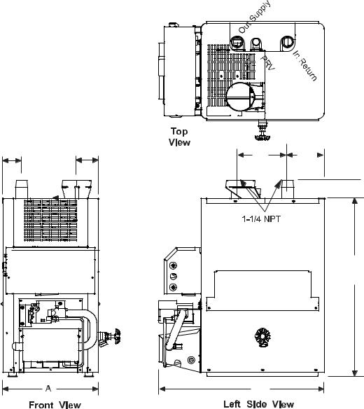
2D. JVH Dimensional Information
Dimensions in inches mm
C |
B |
7 |
6 |
180 |
152 |
|
2.4 |
|
61 |
|
25 |
|
635 |
24 |
|
610 |
|
Size |
A |
|
B |
|
|
C |
Water |
Gas |
|
|
in. |
mm |
in. |
mm |
in. |
|
mm |
Connection |
Connection |
|
|
|
|
|
|
|
|
|
|
50 |
13-3/8 |
340 |
3-1/8 |
79 |
2-7/8 |
|
73 |
1-1/4 |
1/2 |
75 |
13-3/8 |
340 |
2-1/4 |
57 |
2 |
|
51 |
1-1/4 |
1/2 |
100 |
16-7/8 |
429 |
5-3/4 |
146 |
2-7/8 |
|
73 |
1-1/4 |
1/2 |
125 |
16-7/8 |
429 |
5-1/2 |
140 |
2 |
|
51 |
1-1/4 |
1/2 |
160 |
20-3/8 |
518 |
7-1/4 |
184 |
2 |
|
51 |
1-1/4 |
1/2 |
225 |
25-5/8 |
651 |
10 |
254 |
2 |
|
51 |
1-1/4 |
3/4 |
|
|
|
|
|
|
|
|
|
|
JVH Dimensions
Mini-Therm JVJVS |
Page 7 |
|
|
|
|
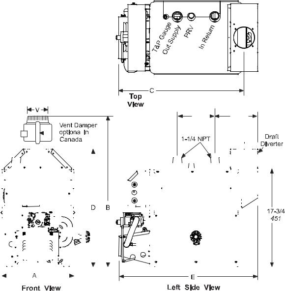
2D. JVS Dimensional Information
Dimensions in inches mm
7 |
9 -1/4 |
|
180 |
|
240 |
|
|
|
|
|
|
|
|
|
|
|
|
|
|
|
|
|
|
|
|
|
|
|
|
|
|
|
|
|
|
|
|
|
|
|
|
|
|
|
|
|
|
|
|
|
|
|
|
|
|
|
|
|
|
|
|
|
|
|
|
|
|
|
|
|
|
|
|
|
|
|
|
|
|
|
|
|
|
|
|
|
|
|
|
|
|
|
|
|
|
|
|
|
|
|
|
|
|
|
|
|
|
|
|
|
|
|
|
|
|
|
|
|
|
|
|
|
|
|
|
|
|
|
|
|
|
|
|
|
|
|
|
|
|
|
|
|
|
|
|
|
|
|
|
|
|
|
|
|
|
|
|
|
|
|
|
|
|
|
|
|
|
|
|
|
|
|
|
|
|
|
|
|
|
|
|
|
|
|
|
|
|
|
|
|
|
|
|
|
|
|
|
|
|
|
|
|
|
|
|
|
|
|
|
|
|
|
|
|
|
|
|
|
|
|
|
|
|
|
|
|
|
|
|
|
|
|
|
|
|
|
|
|
|
|
|
|
|
|
|
|
|
|
|
|
|
|
|
|
|
|
|
|
|
|
|
|
|
|
|
|
|
|
|
|
|
|
|
|
|
|
|
|
|
|
|
|
|
|
|
|
|
|
|
|
|
|
|
|
|
|
|
|
|
|
|
|
|
|
|
|
|
|
|
|
|
|
|
|
|
|
|
|
|
|
|
|
|
|
|
|
|
|
|
|
|
|
|
|
|
|
|
|
|
|
|
|
|
|
|
|
|
|
|
|
|
|
|
|
|
|
|
|
|
|
|
|
|
|
|
|
|
|
|
|
|
|
|
|
|
|
|
|
|
|
|
|
|
|
|
|
|
|
|
|
|
|
|
|
|
|
|
|
|
|
|
|
|
|
|
|
|
|
|
|
|
|
|
|
|
|
|
|
|
|
|
|
|
|
|
|
|
|
|
|
|
|
|
|
|
|
|
|
|
|
|
|
|
|
|
|
|
|
|
|
|
|
|
|
|
|
|
|
|
|
|
|
|
|
|
|
|
|
|
|
|
|
|
|
|
|
|
|
|
|
|
|
|
|
|
|
|
|
|
|
|
|
|
|
|
|
|
|
|
|
|
|
|
|
|
|
|
|
|
|
|
|
|
|
|
|
|
|
|
|
|
|
|
|
|
|
|
|
|
|
|
|
|
|
|
|
|
|
|
|
|
|
|
|
|
|
|
|
|
|
|
|
|
|
|
|
|
|
|
|
|
|
|
|
|
|
|
|
|
|
|
|
|
|
|
|
|
|
|
|
|
|
|
|
|
|
|
|
|
|
|
|
|
|
|
|
|
|
|
|
|
|
|
|
|
|
|
|
|
|
|
|
|
|
|
|
|
|
|
|
|
|
|
|
|
|
|
|
|
|
|
|
|
|
|
|
|
|
|
|
|
|
|
|
|
|
|
|
|
|
|
|
|
|
|
|
|
|
|
|
|
|
|
|
|
|
|
|
|
|
|
|
|
|
|
|
|
|
|
|
|
|
|
|
|
|
|
|
|
|
|
|
|
|
|
|
|
|
|
|
|
|
|
|
|
|
|
|
|
|
|
|
|
|
|
|
|
|
|
|
|
|
|
|
|
|
|
|
|
|
|
|
|
|
|
|
|
|
|
|
|
|
|
|
|
|
|
|
|
|
|
|
|
|
|
|
|
|
|
|
|
|
|
|
|
|
|
|
|
|
|
|
|
|
|
|
|
|
|
|
|
|
|
|
|
|
|
|
|
|
|
|
|
|
|
|
|
|
|
|
|
|
|
|
|
|
|
|
|
|
|
|
|
|
|
|
|
|
|
|
|
|
|
|
|
|
|
|
|
|
|
|
|
|
|
|
|
|
|
|
|
|
|
|
|
|
|
|
|
|
|
|
|
|
|
|
|
|
|
|
|
|
|
|
|
|
|
|
|
|
|
|
|
|
|
|
|
|
|
|
|
|
|
|
|
|
|
|
|
|
|
|
|
|
|
|
|
|
|
|
|
|
|
|
|
|
|
|
|
|
|
|
|
|
|
|
|
|
|
|
|
|
|
|
|
|
|
|
|
|
|
|
|
|
|
|
|
|
|
|
|
|
|
|
|
|
|
|
|
|
|
|
|
|
|
|
|
|
|
|
|
|
|
|
|
|
|
|
|
|
|
|
|
|
|
|
|
|
|
|
|
|
|
|
|
|
|
|
|
|
|
|
|
|
|
|
|
|
|
|
|
|
|
|
|
|
|
|
|
|
|
|
|
|
|
|
|
|
|
|
|
|
|
|
|
|
|
|
|
|
|
|
|
|
|
|
|
|
|
|
|
|
|
|
|
|
|
|
|
|
|
|
|
|
|
|
|
|
|
|
|
|
|
|
|
|
|
|
|
|
|
|
|
|
|
|
|
|
|
|
|
|
|
|
|
|
|
|
|
|
|
|
|
|
|
|
|
|
|
|
|
|
|
|
|
|
|
|
|
|
|
|
|
|
|
|
|
|
|
|
|
|
|
|
|
|
|
|
|
|
|
|
|
|
|
|
|
|
|
|
|
|
|
|
|
|
|
|
|
|
|
|
|
|
|
|
|
|
|
|
|
|
|
|
|
|
|
|
|
|
|
|
|
|
|
|
|
|
|
|
|
|
|
|
|
|
|
|
|
|
|
|
|
|
|
|
|
|
|
|
|
|
|
|
|
|
|
|
|
|
|
|
|
|
|
|
|
|
|
|
|
|
|
|
|
|
|
|
|
|
|
|
|
|
|
|
|
|
|
|
|
|
|
|
|
|
|
|
|
|
|
|
|
|
|
|
|
|
|
|
|
|
|
|
|
|
|
|
|
|
|
|
|
|
|
|
|
|
|
|
|
|
|
|
|
|
|
|
|
|
|
|
|
|
|
|
|
|
|
|
|
|
|
|
|
|
|
|
|
|
|
|
|
|
|
|
|
|
|
|
|
|
|
|
|
|
|
|
|
|
|
|
|
|
|
|
|
|
|
|
|
|
|
|
|
|
|
|
|
|
|
|
|
|
|
|
|
|
|
|
|
|
|
|
|
|
|
|
|
|
|
|
|
|
|
|
|
|
|
|
|
|
|
|
|
|
|
|
|
|
|
|
|
|
|
|
|
|
|
|
|
|
|
|
|
|
|
|
|
|
|
|
|
|
|
|
|
|
|
|
|
|
|
|
|
|
|
|
|
|
|
|
|
|
|
|
|
|
|
|
|
|
|
|
|
|
|
|
|
|
|
|
|
|
|
|
|
|
|
|
|
|
|
|
|
|
|
|
|
|
|
|
|
|
|
|
|
|
|
|
|
|
|
|
|
|
|
|
|
|
|
|
|
|
|
|
|
|
|
|
|
|
|
|
|
|
|
|
|
|
|
|
|
|
|
|
|
|
|
|
|
|
|
|
|
|
|
|
|
|
|
|
|
|
|
|
|
|
|
|
|
|
|
|
|
|
|
|
|
|
|
|
|
|
|
|
|
|
|
|
|
|
|
|
|
|
|
|
|
|
|
|
|
|
|
|
|
|
|
|
|
|
|
|
|
|
|
|
|
|
|
|
|
|
|
|
|
|
|
|
|
|
|
|
|
|
|
|
|
|
|
|
|
|
|
|
|
|
|
|
|
|
|
|
|
|
|
|
|
|
|
|
|
|
|
|
|
|
|
|
|
|
|
|
|
|
|
|
|
|
|
|
|
|
|
|
|
|
|
|
|
|
|
|
|
|
|
|
|
|
|
|
|
|
|
|
|
|
|
|
|
|
|
|
|
|
|
|
|
|
|
|
|
|
|
|
|
|
|
|
|
|
|
|
|
|
|
|
|
|
|
|
|
|
|
|
|
|
|
|
|
|
|
|
|
|
|
|
|
|
|
|
|
|
|
|
|
|
|
|
|
|
|
|
|
|
|
|
|
|
|
|
|
|
|
|
|
|
|
|
|
|
|
|
|
|
|
|
|
|
|
|
|
|
|
|
|
|
|
|
|
|
|
|
|
|
|
|
|
|
|
|
|
|
|
|
|
|
|
|
|
|
|
|
|
|
|
|
|
|
|
|
|
|
|
|
|
|
|
|
|
|
|
|
|
|
|
|
|
|
|
|
|
|
|
|
|
|
|
|
|
|
|
|
|
|
|
|
|
|
|
|
|
|
|
|
|
|
|
|
|
|
|
|
|
|
|
|
|
|
|
|
|
|
|
|
|
|
|
|
|
|
|
|
|
|
|
|
|
|
|
|
|
|
|
|
|
|
|
|
|
|
|
|
|
|
|
|
|
|
|
|
|
|
|
|
|
|
|
|
|
|
|
|
|
|
|
|
|
|
|
|
|
|
|
|
|
|
|
|
|
|
|
|
|
|
|
|
|
|
|
|
|
|
|
|
|
|
|
|
|
|
|
|
|
|
|
|
|
|
|
|
|
|
|
|
|
|
|
|
|
|
|
|
|
|
|
|
|
|
|
|
|
|
|
|
|
|
|
|
|
|
|
|
|
|
|
|
|
|
|
|
|
|
|
|
|
|
|
|
|
|
|
|
|
|
|
|
|
|
|
|
|
|
|
|
|
|
|
|
|
|
|
|
|
|
|
|
|
|
|
|
|
|
|
|
|
|
|
|
|
|
|
|
|
|
|
|
|
|
|
|
|
|
|
|
|
|
|
|
|
|
|
|
|
|
|
|
|
|
|
|
|
|
|
|
|
|
|
|
|
|
|
|
|
|
|
|
|
|
|
|
|
|
|
|
|
|
|
|
|
|
|
|
|
|
|
|
|
|
|
|
|
|
|
|
|
|
|
|
|
|
|
|
|
|
|
|
|
|
|
|
|
|
|
|
|
|
|
|
|
|
|
|
|
|
|
|
|
|
|
|
|
|
|
|
|
|
|
|
|
|
|
|
|
|
|
|
|
|
|
|
|
|
|
|
|
|
|
|
|
|
|
|
|
|
|
|
|
|
|
|
|
|
|
|
|
|
|
|
|
|
|
|
|
|
|
|
|
|
|
|
|
|
|
|
|
|
|
|
|
|
|
|
|
|
|
|
|
|
|
|
|
|
|
|
|
|
|
|
|
|
|
|
|
|
|
|
|
|
|
|
|
|
|
|
|
|
|
|
|
|
|
|
|
|
|
|
|
|
|
|
|
|
|
|
|
|
|
|
|
|
|
|
|
|
|
|
|
|
|
|
|
|
|
|
|
|
|
|
|
|
|
|
|
|
|
|
|
|
|
|
|
|
|
|
|
|
|
|
|
|
|
|
|
|
|
|
|
|
|
|
|
|
|
|
|
|
|
|
|
|
|
|
|
|
|
|
|
|
|
|
|
|
|
|
|
|
|
|
|
|
|
|
|
|
|
|
|
|
|
|
|
|
|
|
|
|
|
|
|
|
|
|
|
|
|
|
|
|
|
|
|
|
|
|
|
|
|
|
|
|
|
|
|
|
|
|
|
|
|
|
|
|
|
|
|
|
|
|
|
|
|
|
|
|
|
|
|
|
|
|
|
|
|
|
|
|
|
|
|
|
|
|
|
|
|
|
|
|
|
|
|
|
|
|
|
|
|
|
|
|
|
|
|
|
|
|
|
|
|
|
|
|
|
|
|
|
|
|
|
|
|
|
|
|
|
|
|
|
|
|
|
|
|
|
|
|
|
|
|
|
|
|
|
|
|
|
|
|
|
|
|
|
|
|
|
|
|
|
|
|
|
|
|
|
|
|
|
|
|
|
|
|
|
|
|
|
|
|
|
|
|
|
|
|
|
|
|
|
|
|
|
|
|
|
|
|
|
|
|
|
|
|
|
|
|
|
|
|
|
|
|
|
|
|
|
|
|
|
|
|
|
|
|
|
|
|
|
|
|
|
|
|
|
|
|
|
|
|
|
|
|
|
|
|
|
|
|
|
|
|
|
|
|
|
|
|
|
Water |
|
Gas |
|
|
|
|
|||||
|
|
|
Size |
|
|
|
|
|
|
|
|
|
|
|
A |
|
|
|
|
|
|
|
|
|
|
|
|
|
|
|
|
B |
|
|
|
|
|
|
|
|
|
|
|
|
|
C |
|
|
|
|
|
|
D |
|
|
|
|
|
|
|
|
|
|
E |
|
|
|
|
|
|
|
|
|
V |
Conn |
Conn |
|
|
|
|
|||||||||||||||||
|
|
|
|
|
|
|
|
|
|
|
in. |
|
mm |
|
|
in. |
mm |
|
|
in. |
mm |
|
in. |
|
mm |
|
in. |
mm |
|
|
in. |
|
|
mm |
1-1/4 |
1/2 |
|
|
|
|
|
|
|||||||||||||||||||||||||||||||||||||||||||||||||||||||
|
50 |
|
|
13-3/8 |
|
340 |
|
|
|
|
27-3/4 |
|
|
|
710 |
|
|
23-5/8 |
600 |
21-3/4 |
|
550 |
26-1/2 |
670 |
4 |
|
|
10 |
1-1/4 |
1/2 |
|
|
|
|
|
|
|||||||||||||||||||||||||||||||||||||||||||||||||||||||||||||
|
75 |
|
|
13-3/8 |
|
340 |
|
|
|
|
27-3/4 |
|
|
|
710 |
|
|
24-1/8 |
610 |
21-3/4 |
|
550 |
27-1/2 |
700 |
5 |
|
|
13 |
1-1/4 |
1/2 |
|
|
|
|
|
|
|||||||||||||||||||||||||||||||||||||||||||||||||||||||||||||
|
100 |
|
|
16-7/8 |
|
430 |
|
|
|
|
28-3/4 |
|
|
|
730 |
|
|
24-1/8 |
610 |
22-3/4 |
|
580 |
27-1/2 |
700 |
5 |
|
|
13 |
1-1/4 |
1/2 |
|
|
|
|
|
|
|||||||||||||||||||||||||||||||||||||||||||||||||||||||||||||
|
125 |
|
|
16-7/8 |
|
430 |
|
|
|
|
28-3/4 |
|
|
|
730 |
|
|
23-5/8 |
600 |
22-3/4 |
|
580 |
27-1/2 |
700 |
6 |
|
|
15 |
1-1/4 |
1/2 |
|
|
|
|
|
|
|||||||||||||||||||||||||||||||||||||||||||||||||||||||||||||
|
160 |
|
|
20-3/8 |
|
518 |
|
|
|
|
28-3/4 |
|
|
|
730 |
|
|
23-5/8 |
600 |
22-3/4 |
|
580 |
27-1/2 |
700 |
6 |
|
|
15 |
1-1/4 |
1/2 |
|
|
|
|
|
|
|||||||||||||||||||||||||||||||||||||||||||||||||||||||||||||
|
225 |
|
|
25-5/8 |
|
651 |
|
|
|
|
31-1/2 |
|
|
|
800 |
|
|
23-1/4 |
590 |
23-3/4 |
|
630 |
27-1/2 |
700 |
7 |
|
|
18 |
1-1/4 |
3/4 |
|
|
|
|
|
|
|||||||||||||||||||||||||||||||||||||||||||||||||||||||||||||
|
|
|
|
|
|
|
|
|
|
|
|
|
|
|
|
|
|
|
|
|
|
|
|
|
|
|
|
|
|
|
|
|
|
|
|
|
|
|
|
|
|
|
|
|
|
|
|
|
|
|
|
|
|
|
|
|
|
|
|
|
|
|
|
|
|
|
|
|
|
|
|
|
|
|
|
|
|
|
|
|
|
|
|
|
|
|
|
|
|
|
|
|
|
|
|
|
|
JVS Dimensions

Page 8 |
LAARS Heating Systems |
|
|
|
|
width and depth of the heater by at least 12 inches (305mm) in all directions. The masonry must be laid with ends unsealed, and joints matched to provide free circulation of air from side to side through the masonry (see Figure 1). If the boiler is installed in a carpeted alcove, the entire floor of the alcove must be covered by a noncombustible platform.
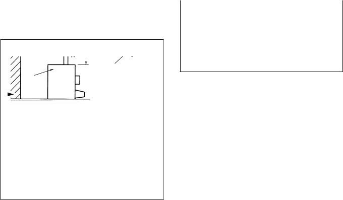
2E. Clearance / Closet Installations
All Mini-Therm JV's can be installed in a closet as long as the minimum clearances are observed.
See Table 2JVH and Figure 2JVH for clearances required for the Mini-Therm JVH.
See Table 2JVS and Figure 2JVS for clearances required for the Mini-Therm JVS
Boiler Sizes |
50 |
- 225 |
Clearances |
in |
cm |
|
|
|
Left side |
2 |
5 |
Right side |
5 |
15 |
|
|
|
Rear |
2 |
5 |
|
|
|
Front |
4 |
10 |
Flue (using B-vent) |
6 |
15 |
|
|
|
Top |
23 |
58 |
Table 2JVH Minimum Boiler Clearances
Special attention should be paid to clearances between the front of the boiler and the closet door when it is closed.
Consult the American National Standard Z21.13 for more information concerning closet installations. In
Canada, refer to the latest edition of CSA-B149.1.
Boiler Sizes |
50 |
- 125 |
160 |
- 225 |
Clearances |
in |
cm |
in |
cm |
|
|
|
|
|
Left side |
6 |
15 |
6 |
15 |
Right side |
6 |
15 |
6 |
15 |
|
|
|
|
|
Rear |
6 |
15 |
6 |
15 |
|
|
|
|
|
Front |
4 |
10 |
4 |
10 |
Flue |
6 |
15 |
6 |
15 |
|
|
|
|
|
Top |
23 |
58 |
36 |
91 |
Table 2JVS Minimum Boiler Clearances
Note: Clearances listed are manufacturer’s tested values. These are given as minimum values. Where local and national codes apply, and values are different than those listed use the greater value to ensure safe operation.
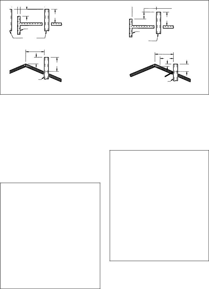
Minimum Boiler Clearances from Combustible Surfaces.
Dégagements Minimaux à Assurer Entre Ics Parois de L’appareil et leo Constructions Combustibles
A |
2 |
|
|
|
(51) |
2 |
|
|
|
|
|
|
|
(51) |
|
|
|
TOP |
6 15 |
|
|
|
|
|
|
VIEW |
|
|
|
4* |
6 15 |
|
|
|
|
|
|
10 |
|
|
|
5 |
|
|
|
(127) |
|
|
6 |
|
6 15 |
|
(152) |
|
|
6 |
|
|
|
|
Dimensions in inches cm. |
|
B |
SIDE |
|
|
|||
(152) |
|
|
|
|
|
|
|
VIEW |
*6" for models JV160 to JV225. |
||||
MIN |
|
|||||
|
||||||
|
|
|
|
|
|
|
Air |
Figure 2JVS. Closet Installation |
|
Openings |
|
|
|
|
Dimensions in |
|
|
inches (mm). |
|
|
|
Figure 2JVH. Closet Installation.

Mini-Therm JV |
Page 9 |
|
|
|
|
SECTION 3.
Air and Venting
3A. Combustion Air Supply
The boiler location must provide sufficient air supply for proper combustion, and ventilation of the surrounding area as outlined in the latest edition of U.S. ANSI standard Z223.1 or in Canada, CAN/ CGA-B149.1 or .2, and any local codes that may be applicable.
In general, these requirements specify that the boiler rooms which represent confined spaces should be provided with two permanent air supply openings; one within 12 inches (305mm) of the ceiling, the other within 12 inches (305mm) of the floor.
NOTE: In Canada, follow Canadian Standard,
CAN/CGA-B149 or local codes.
Outside Air Supply: When combustion air is supplied directly through an outside wall, each opening should have a minimum free area of one square inch per 4,000 BTU/h (6 sq. cm per 1.2 kW) input of the total input rating of all appliances in the enclosed area.
Inside Air Supply: When combustion is supplied from inside the building, each opening should have a minimum free area of one square inch per 1,000
BTU/h (6 sq. cm per 0.3 kW) input of the total input rating of all appliances in the enclosed area. These openings should never be less than 100 square inches (645 sq. cm).
Boiler Size |
Outside Air Area |
Inside Air Area |
||
|
sq. in |
sq. cm |
sq. in. |
sq. cm |
50 |
15 |
97 |
100 |
645 |
75 |
20 |
129 |
100 |
645 |
100 |
25 |
161 |
100 |
645 |
125 |
32 |
206 |
125 |
807 |
160 |
40 |
258 |
160 |
1032 |
225 |
60 |
387 |
225 |
1452 |
*Area indicated is for one of two openings: one at floor level and one at the ceiling, so the total net free area would be double the figures shown. For special conditions, refer to NFPA54 ANSI Z223.1. In Canada, refer to the National Standard CAN1-B149.1 or .2, which differs from this table. NOTE: Check with louver manufacturers for Net Free Area of Louvers. Correct for screen resistance to the Net Free Area if a screen is used.
Table 3. Minimum Recommended Air Supply to Boiler Room
Exhaust Fans or Vents: Any equipment which exhausts air from the boiler room can deplete the combustion air supply or reverse the natural draft action of venting system. This could cause flue products to accumulate in the boiler room. Additional air must be supplied to compensate for such exhaust.
The information in Table 3 is not applicable in installations where exhaust fans or blowers of any type are used. Such installations must be designed by qualified engineers.
If a blower or fan is used to supply air to the boiler room, the installer should make sure it does not create drafts which could cause nuisance shutdowns. If a blower is necessary to provide adequate combustion air to the boiler, a suitable switch or equivalent must
CHIMNEY
CHIMNEY
LINER |
1/4" |
LINER |
1/4" |
|
||||
PER FT. |
|
|||||||
|
|
|||||||
THIMBLE |
(20mm PER M) |
|
PER FT. |
|||||
|
SLOPE |
(20mm PER M) |
||||||
|
|
|
SLOPE |
|||||
|
VENT |
|
|
|
|
|
|
VENT |
|
SYSTEM |
|
|
|
|
|
|
|
|
THIMBLE |
|
|
|
|
|
SYSTEM |
|
|
|
|
|
|
|
|
||
|
|
|
|
|
|
|
(305mm) |
|
CLEANOUT |
|
CLEANOUT |
|
12" |
|
|||
BOILER |
|
|
|
|
|
BOILER |
||
|
|
|
|
|
|
|||
|
|
|
|
|
|
|
|
|
Figure 3. Chimney Venting. |
Figure 4. Vertical Venting. |
Page 10 |
LAARS Heating Systems |
|
|
|
|
10 (3.0) OR
LESS
|
2 (0.6) MIN. |
|
WALL OR |
|
PARAPET |
|
CHIMNEY |
|
10 (3.0) |
|
OR LESS |
|
2 (0.6) |
RIDGE |
MIN. |
|
CHIMNEY |
3 (0.9) MIN.
TERMINATION |
|
|
10 FT. (3.0m) |
|
|
OR LESS FROM RIDGE, |
NOTE: NO HEIGHT |
|
WALL OR PARAPET |
||
ABOVE PARAPET |
||
|
||
|
REQUIRED WHEN |
|
|
FROM WALLS OR |
|
|
PARAPET IS MORE |
|
3 (0.9) |
THAN 10 FT. (3.0m) |
|
|
||
MIN. |
|
Dimensions in feet (m).
MORE THAN 10
(3.0)
3 (0.9) MIN.
WALL OR
PARAPET
CHIMNEY
MORE THAN 10
(3.0)
|
10 (3.0) |
RIDGE |
3 (0.9) |
|
MIN. |
|
2 (0.6) |
|
MIN. |
|
CHIMNEY |
Figure 5. Vertical Vent Termination.
be wired into the boiler control circuit to prevent the boiler from firing unless the blower is operating.
The boiler must be completely isolated and protected from any source of corrosive chemical fumes such as those emitted by trichloroethylene, perchloroethylene, chlorine, etc.
3B. Venting
Vent Categories: Mini-Therm JVS is a natural draft appliance for Category I venting only. JVH is a fan-assisted product that can be vented vertically in a properly-designed Category I system, or can be vented horizontally as a Category III appliance, per this
installation manual.
 WARNING
This boiler must be vented in accordance with Part 7, Venting of Equipment, of the latest edition of the National Fuel Gas code, ANSI Z223.1 and all applicable local building codes. In Canada, follow CAN/CGA B149 Installation codes.
Improper venting of this appliance can result in excessive levels of carbon monoxide which can result in severe personal injury or death!
 AVERTISSEMENT
Cette chaudière doit être ventilé, conformément aux dispositions de la partie 7, de la ventilation de l'équipement, de la dernière édition du National gaz carburant code, ANSI Z223.1 et tous les codes du bâtiment locaux. Au Canada, CAN/ CGA B149 codes d'installation. Une mauvaise ventilation de cet appareil peut entraîner des niveaux excessifs de monoxyde de carbone qui peut entraîner de graves blessures ou la mort!
The boiler vent collar must be fastened directly to an unobstructed vent pipe with rustproof sheet metal screws no longer than 1/2” (13mm) and located to prevent interference with the inducer damper.
Do not weld the vent pipe to the boiler collar. The weight of the stack must not rest on the boiler. The boiler top must be easily removable for normal boiler service and inspection.
 IMPORTANT
Only JVH (induced draft) models may be side-wall vented per Section 3D without the addition of a properly sized and installed power venter.
JVS must be connected only using Category Type
I methods and materials per Section 3C. JVH may be connected per Category I or III (See Section 3D) methods and materials. See fuel gas code for more information regarding your venting application.
 IMPORTANT
Seulement JVH (induits projet) modèles peut être paroi ventilé par chapitre 3D sans l'addition de la bonne taille et de puissance installée venter. JVS doivent être connectés uniquement en utilisant Type de catégorie I méthodes et matériaux par Section 3C. JVH peut être connecté par catégorie
I ou III (voir section 3D) Les méthodes et les matériaux. Voir gaz combustible code pour plus d'informations concernant votre application d'aération.
Avoid terminating boiler vents near air conditioning or air supply fans. The fans can pick up exhaust
flue products from the boiler and return them to the building, creating a possible health hazard.
Avoid oversized vent pipe or extremely long runs
Mini-Therm JV |
Page 11 |
|
|
|
|
of the pipe, which may cause excessive cooling and condensation.
3C. Vertical Venting - Category I
(JVS and JVH)
All venting must comply with fuel gas code and
be installed by a licensed professional.
The Mini-Therm JVS or JVH series boiler can be vented into a masonry chimney, (see Figure 2) provided several conditions are met:
1.The chimney must have an appropriate tile lining that is clean, properly constructed and properly sized.
2.The chimney passage way shall be examined to ascertain that it is clear and free of obstructions.
3.If a chimney rebuild is required, it shall conform to nationally recognized standards (see National Building Code or ANSI/NFPA 211).
4.The boiler must not be connected to a fireplace, wood stove or other solid fuel burning equipment.
5.When the boiler and a hot water heater are to be connected to the same chimney, they must have their own vent connector and enter the chimney at least 6” (152mm) apart.
IMPORTANT NOTE: Always provide a minimum clearance of 6” (152mm) between Type C (single wall) vent pipe and any combustible materials.
 WARNING
Do not store any chemical, cleaners, or other corrosive material near combustion air openings or in the room. Avoid locating dryer vents in the vicinity of combustion air openings. Failure to prevent corrosive materials from mixing with combustion air can result in reduced boiler life and unsafe boiler operation.
 AVERTISSEMENT
N’entrepposer aucun produit chimique, produit nettoyant ou produit corrosif à proximité des bouches d’air de combustion ou dans la pièce.
Éviter de placer des tuyaux de ventilation pour sécheuse à proximité des bouches d’air de combustion. Le fait de laisser des maitières corrosives se mélanger à l’air de combustion risque de réduire le cycle de vie de l’appareil de chauffage et de compromettre son fonctionnement.
 WARNING
Single wall vent pipe must NEVER pass through interior walls or through floors or ceilings! Failure to comply with this warning could result in a fire causing property damage, personal injury, or death!
 AVERTISSEMENT
Paroi simple tuyau d'évent doit jamais passer par l'intérieur les murs ou par planchers ou plafonds ! Le non-respect de cet avertissement peut provoquer un incendie causant des dommages matériels ou corporels, ou de mort!
When installing the vent system, all applicable national and local codes must be followed! The use of thimbles, firestops and other protective devices, when penetrating combustible or noncombustible
construction, must be in accordance with all applicable national and local codes.
4 (1.2)
MIN. 4 (1.2) MIN.
VENT |
12 (3.7) |
TERMINAL |
|
|
MIN. |
Dimensions in feet (m).
|
|
SEAL ENTIRE |
|
|
|
CIRCUMFERENCE |
|
|
VENT TERMINAL |
OF JOINT |
|
|
|
|
|
|
|
CAULK JOINTS |
CAULK JOINTS |
|
ANCHORED |
||
|
ANCHORED |
||
VENT TERMINAL |
|
FASTENER |
|
|
|
FASTENER |
|
|
LESS THAN |
|
|
|
|
|
|
3 (0.9) |
10 |
|
EXHAUST |
MIN. |
(3.0) |
|
HOOD |
6 (1.8) MIN.
GRADE
FORCED
AIR INLET
THIMBLE
SHEET METAL
SCREWS
VENT TERMINAL DETAIL
Figure 6. Horizontal Vent Termination.
Page 12 |
LAARS Heating Systems |
|
|
|
|
Vertical vents of the induced draft JVH boilers must be installed in accordance with the code requirement for Category 1, Fan Assisted Appliances. Follow the requirements as indicated in the latest edition of ANSI
Z223.1/NFPA 54, sizing of Category I Venting System and Appendix G, or in Canada, follow the instruction of CAN/CGA-B149 installation code.
An unused lined chimney can be used as a raceway for single wall vent pipe, (see Figure 3). Never run vent pipe through a flue that has another appliance attached to it.
3D-1. Horizontal Venting - Category III
(JVH only)
When venting is horizontal, or cannot meet the requirements of Category I, it can develop positive pressure and must be installed in accordance with this section and the specific vent manufacturer’s instructions. Common venting is not allowed in Category III systems.
|
|
|
|
BOILER VENTING |
|
|
|
|
DETAIL |
|
OUTSIDE WALL |
|
|
|
|
|
VENT |
SHEET METAL |
|
|
|
SYSTEM |
||
|
|
SCREWS |
||
|
|
|
||
|
|
THIMBLE |
* |
12" (305mm) |
|
|
|||
|
|
|
|
MIN. |
|
|
|
|
CAULK ENTIRE |
|
|
BOILER |
|
JOINT, INCLUDING |
|
|
|
THE SCREWS |
|
|
|
|
|
|
|
|
VENT TERMINAL |
|
*WHEN HORIZONTAL RUN |
|
|
HOOD |
|
EXCEEDS 5 FT. (1.5m) |
Figure 7. Horizontal Venting.
3D-2. Vent Connections (JVH only)
The vent system must be gas tight. All seams and joints must be sealed with silicone sealant or adhesive tape having a minimum temperature rating of 400°F (204ºC). Use at least three corrosion resistant screws at each slip joint, when required.
For best results, horizontal vent systems should be as short and straight as possible. Material of vent connectors shall be as follows:
Description |
|
Manufacturer |
Product |
||
High Temperature |
|
Dow Corning |
|
Trade Mate |
|
RTV |
|
|
|||
|
|
|
|
|
|
2" (51mm) wide |
|
|
|
|
Product |
Aluminum foil tape |
|
Venture |
|
||
|
|
#3243 |
|||
- adhesively backed |
|
|
|
|
|
|
|
|
|
|
|
2" (51mm) wide |
|
|
|
|
|
Aluminum foil tape |
|
3M |
|
Product #433 |
|
- adhesively backed |
|
|
|
|
|
Vent |
Sealing Materials. |
|
|||
|
|
|
|
|
|
Materials |
|
|
|
Vent Length |
|
In U.S.A.: UL type 304, 316 or 294-C |
|
Up to a maximum |
|||
stainless steel or equal 26 gauge minimum. |
|
of 55' (17m) of |
|||
In Canada: Use "BH-Type" vent |
|
equivalent pipe run |
|||
material certified to ULD-S636 Class I |
|
(including required |
|||
(more than 135°C, but not more than 245°C |
|
elbows). |
|||
flue gas temperature), made of AL29-4C |
|
|
|
||
stainless steel or equal. |
|
|
|
|
|
|
|
|
|
|
|
Do not use plastic venting of any kind.
The boiler vent collar must be fastened to the vent pipe with rustproof metal screws no longer than 1/2” (13mm) and sealed with high temperature (500ºF / 260ºC) silicone sealant. For larger diameter vent pipes, use a sealed reducer fastened directly to the boiler collar and seal all joints as indicated in Figure 7.
Allow the sealant to cure for 24 hours before operating the boiler.
The entire vent system must not exceed the size specified in Table 4.
The following criteria must be observed:
1.Attach a vertical pipe at least 12” (305mm) high to the boiler outlet before the horizontal run if run exceeds 5 feet (see Figure 5).
2.Support the vent run at 3’(.9m) intervals with overhead hangers.
Size |
|
Diameter |
No. of |
Horizontal Run Length |
||
in. |
|
mm |
Elbows |
ft. |
m |
|
|
|
|||||
50 - 160 |
4 |
|
102 |
4 |
35 |
10.7 |
225 |
4 |
|
102 |
2 |
10 |
3.0 |
225 |
6 |
|
152 |
4 |
35 |
10.7 |
For each elbow eliminated, add 5’ (1.5m) of allowable vent.
Table 4. Horizontal Venting Configuration.
3.Pitch down the vent run, toward the vent terminal
(hood), 1/4” per foot (20mm per meter).
4.Do not locate any joint screws at the bottom of the vent run.
3D-3. Vent Termination (JVH only)
The side wall vent terminal (hood), Laars Part
 Loading...