

Page 1
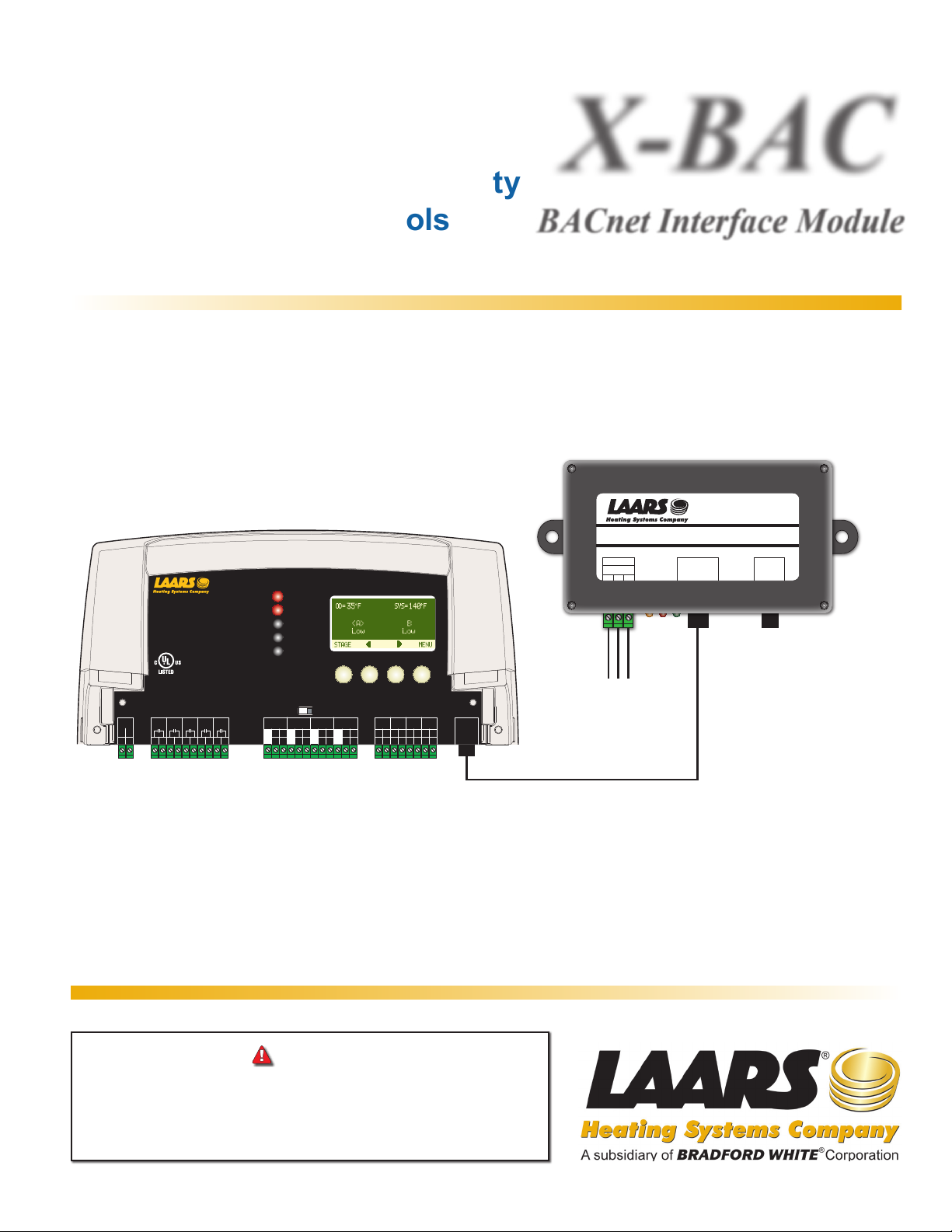
Installation and Operation Manual
Adds BACnet MSTP Capability
Document 4233
X-BAC
to Laars M4-LHS Controls
PWR
L
N
1
2
OUTPUT RATINGS:
120VAC, 6A RESISTIVE
1A PILOT DUTY, 15A TOTAL
FOR ALL CIRCUITS
INPUT RATINGS:
115VAC 60Hz , 30VA MAX
USE COPPER WIRE,
CLASS 1 WIRE ONLY.
ENCLOSED
ENERGY
MANAGEMENT
EQUIPMENT
99RA
CAUTION
: RISK OF ELECTRIC SHOCK
More than one disconnect switch may be required
to de-energize the equipment before servicing.
SYS
A
B
C
5
3
6
4
7
8
9
10
11
D
12
M4-LHS
A
B
C
D
A
B
CUR / VLT
CUR / VLT
GND
mA
VLT
GND
mA
-
-
+
+
+
13
15
16
14
17
RUNPROGRAM
C
CUR / VLT
VLT
GND
mA
-
+
+
18
19
20
HYBRID CONTROL
D
CUR / VLT
VLT
GND
mA
mA
VLT
-
+
+
+
+
23
21
22
24
DO NOT APPLY ANY VOLTAGE
TO INPUT TERMINALS
OUTDOOR
SYSTEM
PROVE
TEMP
TEMP
/DHW
T
O
T
O
O
25
26
28
29
27
30
SHUTDOWN
/TSTAT
/SETBACK
31
O
32
EXTENSION
MODULE
RS-485
BACnet Interface Module
X-BAC
BACnet Interface Module
MSTP
A GND B
1 2 3
B (-)
A (+)
Ground
To BACnet
MSTP
PRODUCT
COMM
RS485
WARNING
This control is strictly an operating control; it should never be
used as a primary limit or safety control. All equipment must have
its own certified limit and safety controls required by local codes.
The installer must verify proper operation and correct any safety
problems prior to the installation of this control.
RJ45 Communication Cable
HT# 059294-00 B
Page 2

CONTENT
Overview. . . . . . . . . . . . . . . . . . . . . . . . . . . . . . . . . . . . . . . . . . . . . . . . . . . . . . . . . 3
Item List . . . . . . . . . . . . . . . . . . . . . . . . . . . . . . . . . . . . . . . . . . . . . . . . . . . . . . . . . 3
Installation. . . . . . . . . . . . . . . . . . . . . . . . . . . . . . . . . . . . . . . . . . . . . . . . . . . . . . . . 3
Wiring . . . . . . . . . . . . . . . . . . . . . . . . . . . . . . . . . . . . . . . . . . . . . . . . . . . . . . . . . . 3
BACnet MS/TP Wiring . . . . . . . . . . . . . . . . . . . . . . . . . . . . . . . . . . . . . . . . . . . . . . . . . 3
Connecting to Control. . . . . . . . . . . . . . . . . . . . . . . . . . . . . . . . . . . . . . . . . . . . . . . . . 4
Connecting to Extension . . . . . . . . . . . . . . . . . . . . . . . . . . . . . . . . . . . . . . . . . . . . . . . 4
BACnet Startup Menu Setup . . . . . . . . . . . . . . . . . . . . . . . . . . . . . . . . . . . . . . . . . . . . . . 5
BACnet Mode . . . . . . . . . . . . . . . . . . . . . . . . . . . . . . . . . . . . . . . . . . . . . . . . . . . . . 5
BACnet Baud Rate. . . . . . . . . . . . . . . . . . . . . . . . . . . . . . . . . . . . . . . . . . . . . . . . . . . 5
MS/TP Address . . . . . . . . . . . . . . . . . . . . . . . . . . . . . . . . . . . . . . . . . . . . . . . . . . . . 5
BACnet ID . . . . . . . . . . . . . . . . . . . . . . . . . . . . . . . . . . . . . . . . . . . . . . . . . . . . . . . 5
LED . . . . . . . . . . . . . . . . . . . . . . . . . . . . . . . . . . . . . . . . . . . . . . . . . . . . . . . . . . . 5
Troubleshooting . . . . . . . . . . . . . . . . . . . . . . . . . . . . . . . . . . . . . . . . . . . . . . . . . . . . 6
No LED Lights . . . . . . . . . . . . . . . . . . . . . . . . . . . . . . . . . . . . . . . . . . . . . . . . . . . . . 6
No Communication. . . . . . . . . . . . . . . . . . . . . . . . . . . . . . . . . . . . . . . . . . . . . . . . . . . 6
Specication . . . . . . . . . . . . . . . . . . . . . . . . . . . . . . . . . . . . . . . . . . . . . . . . . . . . . . 6
Wiring to Control and Extension. . . . . . . . . . . . . . . . . . . . . . . . . . . . . . . . . . . . . . . . . . . . 7
HT# 059294-00 B
2
X-BAC BACnet Interface Module Installation and Conguration Manual
Page 3
OVERVIEW
BACnet Interface Module
PRODUCT
COMM
RS485
X-BAC
MSTP
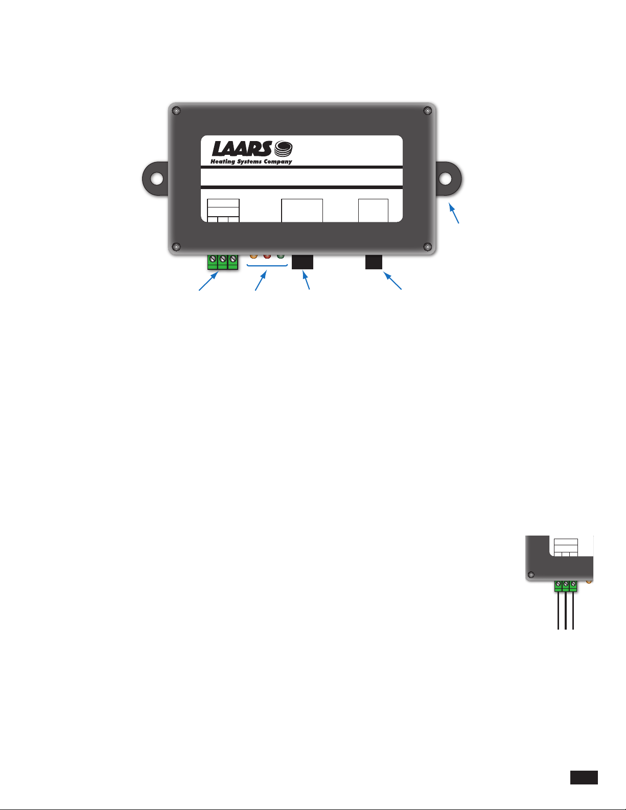
The BACnet Interface Module adds BACnet MS/TP communication capability to the M4-LHS control. It does that by connecting
to both, the control and the BACnet MS/TP network. All the BACnet settings are congured through the control. The BACnet
Interface Module has LEDs that can help in displaying communication status.
X-BAC
BACnet Interface Module
RS485
to EMS
MSTP
A GND B
1 2 3
Operation
LEDs
PRODUCT
COMM
RJ45
Communication
RS485
Mounting
Tab
RJ11
to Extension
to Control
ITEM LIST
• X-BAC BACnet Interface Module,
• RJ45 cables (Ethernet Cable),
INSTALLATION
The BACnet Interface Module communicates with the M4-LHS control using the RJ45 cable. Thus, it needs to be installed in close
proximity to the control.
• Mount the BACnet Interface Module on a at surface next to the control.
• The module can be mounted horizontally or vertically.
• Keep the module away from extreme heat, cold, or humidity.
• Screw the module to the at surface using the two side tabs with holes.
• No need to remove the BACnet Interface Module cover.
WIRING
• No power wiring is required for the BACnet Interface Module. It gets its power through the control's
RJ45 connection.
• The module's MS/TP terminals are of the removal type. That facilitates easy wiring. Just unscrew the
terminal block side screws to remove the full terminal block.
BACNET MS/TP WIRING
• Use 18# AWG Twisted Pair cable. The cable length must not exceed 3500 feet.
• Connect the MS/TP cable coming from the BACnet MS/TP network to the MS/TP terminals on the
BACnet Interface Module. Communication on the BACnet MS/TP network is polarity sensitive.
• The ground terminal (GND) MUST be connected to the BMS Ground.
X-BAC BACnet Interface Module Installation and Conguration Manual
MSTP
A GND B
1 2 3
B (-)
A (+)
Ground
To BACnet
HT# 059294-00 B
3
Page 4

CONNECTING TO CONTROL
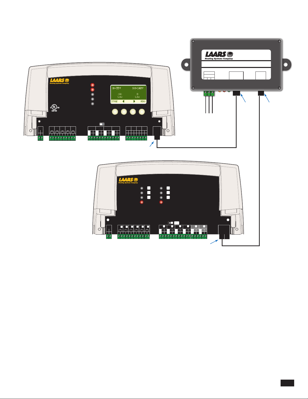
• The BACnet Interface Module communicates all of its information to the control using RJ45 cable (the cable is provided with the
module).
• Both the BACnet Interface Module and the control have RJ45 sockets.
CONNECTING TO EXTENSION
• Unlike the heating control, the extension has a RJ11 Socket. In addition, each extension is packaged with an RJ11 cable to connect
to the control. See "Wiring to Control and Extension" on page 7.
• If an extension is being used, use the RJ11 (RS485) socket on the BACnet module to connect to the extension. See "Item List" on
page 3.
HT# 059294-00 B
4
X-BAC BACnet Interface Module Installation and Conguration Manual
Page 5
BACNET STARTUP MENU SETUP
BACnet Interface Module
RS485
X-BAC
-------- SETTINGS ----
Season Winter
System Target 140
<System Settings>
<Maintenance>
<System Startup>
BACK ▲ ▼ SELECT
---- BACNET ID ----
o
F
477000
[ ]
BACK ▲ ▼ SAVE
-- ARE YOU SURE? --
No
Yes
BACK ▲ ▼ SAVE
----MS/TP ADDRESS----
1
[ ]
BACK ▲ ▼ SAVE
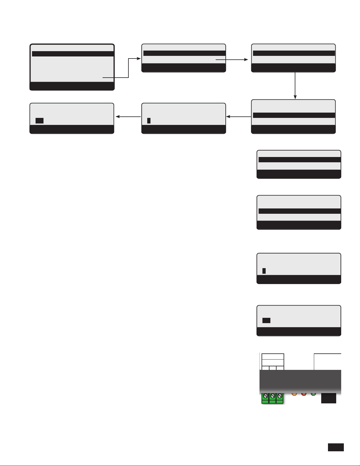
BACNET MODE
Enable, Disable Default: Disable
Button: MENU/<System Startup>/.... Sensor Fault/BACnet Mode
• This menu option enables or disables the BACnet MSTP capability. When enabled,
additional BACnet settings shall be available for further customizing.
BACNET BAUD RATE
9600, 19200, 38400 Default: 19200
Button: MENU/<System Startup>/.... Sensor Fault/BACnet Mode/BACnet Baudrate
• For the control to communicate over a BAcnet MS/TP network, it must use the same Baud
rate as the rest of the network. The control offers three Baud Rates.
• If communication was not successful, the baud rate could be the cause. Check with the
network administrator for the network baud rate. Then match it on the control.
--- BACNET MODE ---
Disable
Enable
BACK ▲ ▼ SAVE
- BACNET BAUDRATE -
9600
19200
38400
BACK ▲ ▼ SAVE
--- BACNET MODE ---
Disable
Enable
BACK ▲ ▼ SAVE
- BACNET BAUDRATE -
9600
19200
38400
BACK ▲ ▼ SAVE
MS/TP ADDRESS
1 to 127 Default: 64
Button: MENU/<System Startup>/.... /BACnet Mode/BACnet Baudrate/ MSTP Address
• Each device on the MS/TP network must have a unique address.
• This is the MS/TP address on a RS485 network. Its MS/TP range is 1 though 127.
• The MS/TP address must be provided by the Network Administrator.
BACNET ID
1 to 4,000,000 Default:
Button: MENU/<System Startup>/.... / MSTP Address / BACnet ID
• The BACnet ID is a unique 32 bit number that identies the control within the BACnet
network. No two ID shall be the same even if dealing across networks.
• It must be provided by the BACnet Network Administrator.
LED
Yellow LED Flashes on communication between the BACnet Interface Module and the
control.
Green LED Flashes on communication between the BACnet Interface Module and the
BACnet network.
Red LED Flashes steadily to indicate the BACnet Interface Module is operational.
----MS/TP ADDRESS----
1
[ ]
BACK ▲ ▼ SAVE
---- BACNET ID ----
[ ]
BACK ▲ ▼ SAVE
MSTP
A GND B
1 2 3
PRODUCT
COMM
X-BAC BACnet Interface Module Installation and Conguration Manual
HT# 059294-00 B
5
Page 6

TROUBLESHOOTING
NO LED LIGHTS
• The RJ45 connection to the control powers the BACnet Interface Module. If all LEDs are off, then check the cable connecting the
module to the control. The cable consist of 8 wires. Check each of the color-coded wires continuity in the cable using a continuity
meter.
NO COMMUNICATION
• Check the Yellow and Green LEDs. If the Yellow LED is continuously On or Off, then check the cable connecting the module to
the control.
• If the Green LED is continuously On or Off, then check the cable connecting the module to the BACnet network.
• Make sure that the control's Baud Rate and the BACnet Network's are the same. See "BACnet Baud Rate" on page 5.
SPECIFICATION
Control Communication . . . . . . . . . . . . . . . . . . . . . . . . . . RJ45 to control (Cable is provided)
BACnet MS/TP Communication . . . . . . . . . . . . . . . . . . . . . . . . . . . . . . . . . . . . 3-wire
Extension Communication. . . . . . . . . . . RS485 (RJ11) to Extension (Cable packaged with Extension)
LEDs . . . . . . . . . . . . . . . . . . . . . . . . . . . . . . . . . . . . . . . . . . Red, Yellow, and Green
Dimension . . . . . . . . . . . . . . . . . . . . . . . . . . . . . . . . . . . . . . . . . . .6-¾” x 3-⅝” x 1”
Weight . . . . . . . . . . . . . . . . . . . . . . . . . . . . . . . . . . . . . . . . . . . . . . . . . 1 Pound
HT# 059294-00 B
6
X-BAC BACnet Interface Module Installation and Conguration Manual
Page 7
WIRING TO CONTROL AND EXTENSION
PWR
L
N
1
2
OUTPUT RATINGS:
120VAC, 6A RESISTIVE
1A PILOT DUTY, 15A TOTAL
FOR ALL CIRCUITS
INPUT RATINGS:
115VAC 60Hz , 30VA MAX
USE COPPER WIRE,
CLASS 1 WIRE ONLY.
ENCLOSED
ENERGY
MANAGEMENT
EQUIPMENT
99RA
CAUTION
: RISK OF ELECTRIC SHOCK
More than one disconnect switch may be required
to de-energize the equipment before servicing.
SYS
A
B
C
5
3
6
4
7
8
9
10
11
D
12
M4-LHS
A
B
C
D
A
B
CUR / VLT
CUR / VLT
GND
mA
VLT
GND
mA
-
-
+
+
+
13
15
16
14
17
VLT
18
+
RUNPROGRAM
CUR / VLT
GND
-
19
20
C
mA
+
HYBRID CONTROL
D
CUR / VLT
VLT
GND
mA
mA
VLT
-
+
+
+
+
23
21
22
24
DO NOT APPLY ANY VOLTAGE
TO INPUT TERMINALS
OUTDOOR
SYSTEM
PROVE
TEMP
TEMP
/DHW
T
O
T
O
O
25
26
28
29
27
30
SHUTDOWN
/TSTAT
/SETBACK
31
EXTENSION
MODULE
RS-485
O
32
X-BAC
BACnet Interface Module
MSTP
A GND B
1 2 3
B (-)
A (+)
Ground
To BACnet
MSTP
PRODUCT
COMM
RJ45 RJ11
RJ45 Cable
RS485
PWR
L N
1 2
K M OL N P
E
3 4F5 6G7 8H9 10I11 12
RJ45
RJ45 Communication Cable
Extension
M4Ext
FULL MODULATION SEQUENCING EXTENSION
K
E
M
G
O
I
Comm
J
13 14
L
F
N
H
J
P
Power
CAUTION:
More than one disconnect switch may be required
to de-energize the equipment before servicing.
Ext A
Ext B
K ML N
E F G H
CUR / VLT
CUR / VLT
CUR / VLT
GND
VLTmA
VLTmAGND
GND
GND
21
1716
201916
15
18
VLTmAGND
232219
OUTPUT RATINGS:
120VAC, 6A RESISTIVE
1A PILOT DUTY, 15A TOTAL
FOR ALL CIRCUITS
INPUT RATINGS:
115VAC 60Hz, 12VA MAX
Use Copper Conductors Only.
Risk of Electric Shock.
O P
I J
CUR / VLT
CUR / VLT
CUR / VLT
VLTmAGND
VLTmA
GND
GND
24
GND
262522
2928
27
30
VLTmAGND
323116
EXTENSION
MODULE
RS-485
RJ11
RJ11 Extension Cable
X-BAC BACnet Interface Module Installation and Conguration Manual
HT# 059294-00 B
7
Page 8

HT# 059294-00 B
20 Industrial Way, Rochester, NH 03867 • 603.335.6300 • FAX 603.335.3355
1355 Kuehner Drive, Simi Valley, CA 93063 • 800.900.9267 • FAX 800.559.1583 (Sales, Service)
1869 Sismet Road, Mississauga, Ontario, Canada L4W 1W8 • 905.238.0100 • FAX 905.366.0130
www.laars.com Litho in U.S.A © Laars Heating Systems 0911 Document 4233
 Loading...