

Page 1
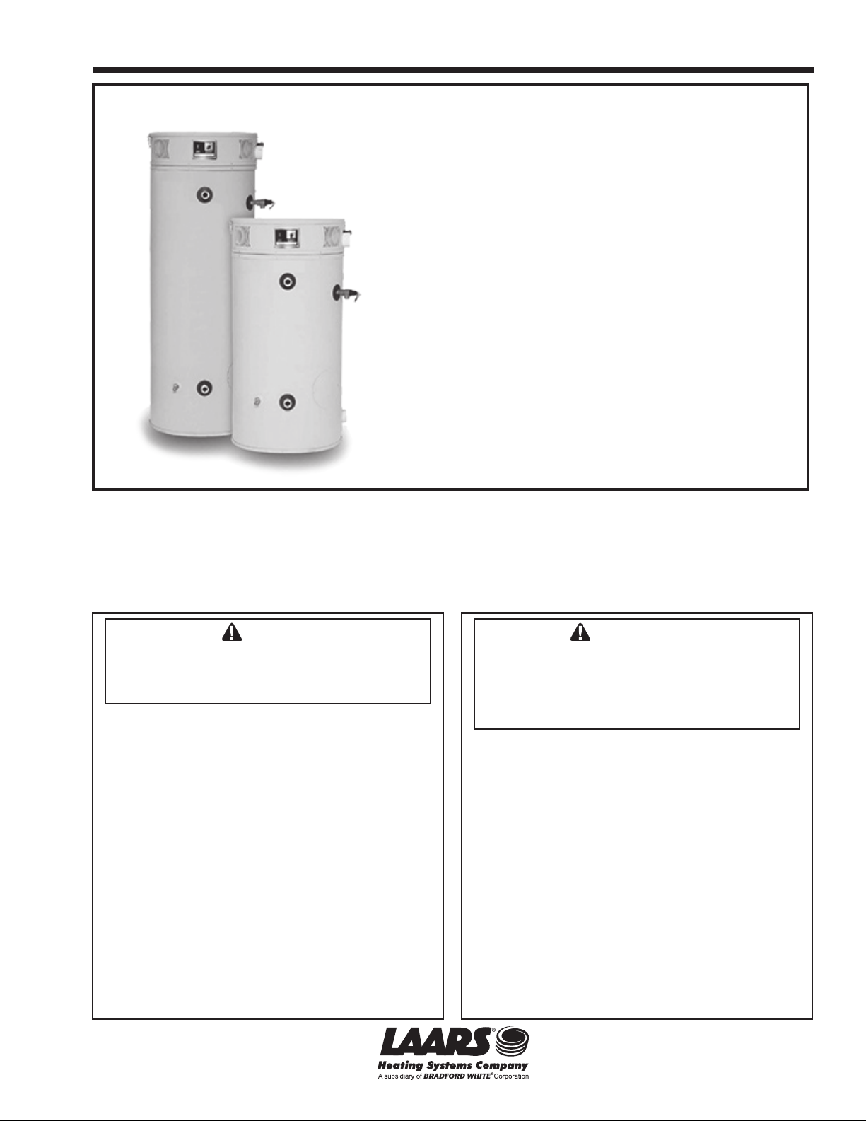
Service Manual Document 11019A
Service Manual for
U.H.E.
Ultra High Efciency
Water Heaters
UHE60T125E*(NA,XA)(2)
UHE60T150E*(NA,XA)(2)
UHE60T199E*(NA,XA)(2)
UHE100T150E*(NA,XA)(2)
UHE100T199E*(NA,XA)(2)
UHE100T250E*(NA,XA)(2)
UHE100T300E*(NA,XA)(2)
UHE100T399E*(NA,XA)(2)
(*) Denotes Warranty Years
Troubleshooting Guide and Instructions for Service
These instructions are to be stored next to the boiler for reference purposes.
FOR YOUR SAFETY: This product must be installed and serviced by a professional service technician,
qualied in hot water boiler installation and maintenance. Improper installation and/or operation could
create carbon monoxide gas in ue gases which could cause serious injury, property damage, or death.
Improper installation and/or operation will void the warranty.
WARNING
If the information in this manual is not followed
exactly, a re or explosion may result causing
property damage, personal injury or loss of life.
Do not store or use gasoline or other ammable
vapors and liquids in the vicinity of this or any
other appliance.
WHAT TO DO IF YOU SMELL GAS
• Do not try to light any appliance.
• Do not touch any electrical switch; do not use
any phone in your building.
• Immediately call your gas supplier from a
nearby phone. Follow the gas supplier's
instructions.
• If you cannot reach your gas supplier, call the
re department.
Installation and service must be performed by
a qualied installer, service agency, or gas
supplier.
Assurez-vous de bien suivres les instructions
données dans cette notice pour réduire au
minimum le risque d’incendie ou d’explosion
ou pour éviter tout dommage matériel, toute
blessure ou la mort.
Ne pas entreposer ni utiliser d’essence ni
d’autres vapeurs ou liquides inammables dans
le voisinage de cet appareil ou de tout autre
appareil.
QUE FAIRE SI VOUS SENTEZ UNE ODEUR DE GAZ:
• Ne pas tenter d’allumer d’appareils.
• Ne touchez à aucun interrupteur. Ne pas
vous servir des téléphones dansle bâtiment
où vous êtes.
• Appelez immédiatement votre fournisseur de
gaz depuis un voisin. Suivez les instructions
du fournisseur.
• Si vous ne pouvez rejoindre le fournisseur
de gaz, appelez le sservice des incendies.
L’installation et l’entretien doivent être assurés
par un installateur ou un service d’entretien
qualié ou par le fournisseur de gaz.
AVERTISSEMENT
Page 2
Page 2
LAARS Heating Systems
U.H.E. Series Commercial Gas
Ultra High Efciency Water Heaters
Table of Contents
Page U.H.E.
Service Procedure
Introduction 3 - - -
How to use this manual 4 - - -
Tool required for service 4 - - -
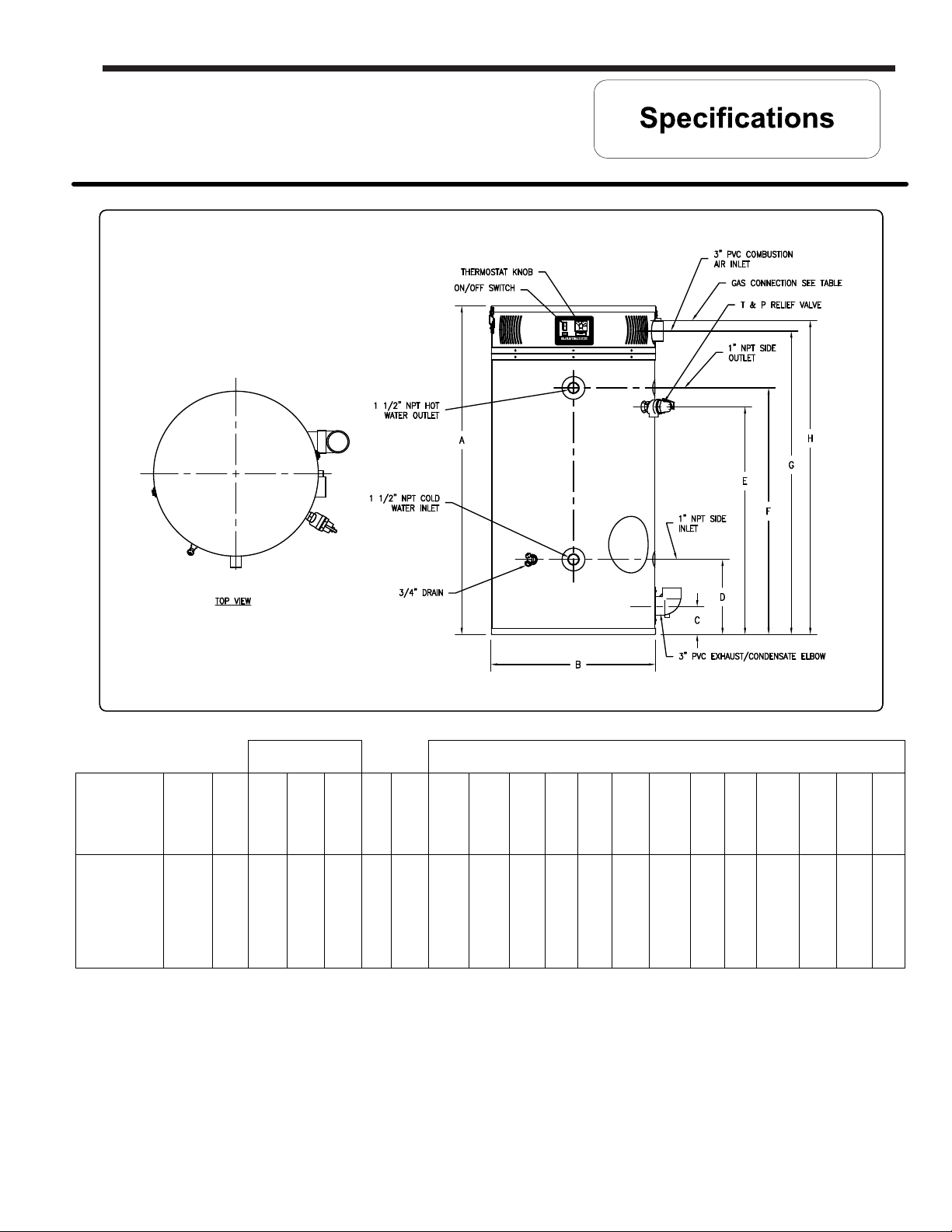
Specifications 5 - - -
Sequence of Operation 8 - - -
Troubleshooting 10 - - -
Thermostat Circuit, Testing & Replacement 12 I
Combustion System Testing and Replacement 18 II
Burner Tube Inspection & Replacement 22 III
Gas Valve Replacement 24 IV
Blower Testing and Replacement 25 V
Exhaust Pressure Switch Testing and Replacement 27 VI
Hot Surface Igniter Testing and Replacement 30 VII
Flame Sensor Testing and Replacement 32 VIII
TM
Ignition Module/Control Board Replacement 34 IX
Transformer Replacement 35 X
Vent Safety Switch Testing and Replacement 36 XI
Anode & Flue Baffle Inspection and Replacement 38 XII
Installation Check List 43 - - -
Heater Service Report 44 - - -
Parts List 45 - - -
Glossary of Terms 48 - - -
2
Page 3

U.H.E Service Manual
U.H.E. Series Commercial Gas
Ultra High Efciency Water Heaters
Introduction
The LAARS heating system Ultra High Efficiency Water Heater is designed to
deliver a remarkable thermal efficiency rating in a quiet running unit with venting
options that allow for installation flexibility. Several technologically advanced
design features are incorporated in the design that will require additional
knowledge on the part of the qualified service provider. The information in this
manual will instruct service and maintenance professionals on the function, proper
diagnosis and repair of LAARS Heating System Ultra High Efficiency Water
Heater.
Page 3
The LAARS heating system Ultra High Efficiency Water Heater uses a low Nox
premix power burner located at the top of the water heater to direct a turbulent
flame down into a submerged combustion chamber. This turbulence causes a
thorough mixing of gas and air for optimum combustion. The combustion gases
then travel through a three pass flue system keeping the gases moving at a high
velocity. The combination of high turbulence and velocity results in an optimum
transfer of heat from the flue gases into the water.
Burner operation is controlled using an electronic ignition module. The module
monitors the status of the electronic thermostat, vent temperature limit switch, vent
system pressure switches and a flame sensor to control output voltage to blower
motor, hot surface igniter and gas valve. The module contains programming which
determines the sequence of operation and timings for purge periods, trial for
ignition, flame sensing and lockout. The module will also provide diagnostic
information to help in determining the cause of system lockouts.
The contents in this manual are detailed informational tools to assist in the proper
diagnosis of the Ultra High Efficiency Water Heater operational faults. Please read
this service manual completely and provide as much information regarding the
Ultra High Efficiency Water Heater operation and installation specific concerns.
Page 4
Page 4
It is intended for this manual to be used by qualified service personal for the primary purpose
of troubleshooting analysis and repair of the LAARS heating system Ultra High Efficiency
Water Heater. Understanding the sequence of operation section of this manual will contribute
greatly to troubleshooting this product.
An “Installation Check List” is shown on page 43. Compare the installation against the
installation check list to confirm all requirements are met.
An “UHE Service Report” is shown on page 44. Completing this form will assist in the
troubleshooting efforts. Should you need to call for technical support, Please provide the
information shown on this form to the support technician to insure accurate troubleshooting.
Troubleshooting begins with “System Observation” to determine failure mode as indicated by
the LED status of the ignition module. Troubleshooting continues with “Failure Modes and
Probable cause” listed on page 10 directing the service provider to a series of test
procedures to determine root cause of failure. Component replacement procedures directly
follow the test procedures for a given component.
LAARS Heating Systems
In some difficult to diagnose conditions, it may be necessary to isolate the heater from the
vent system to determine root cause.
Contact Technical support immediately if diagnosis is not determined using the methods
described in this service manual.
Tools Required for Service
Manometer: Two types available, a liquid “U” tube type or a digital (magna-helic)
type. This device is used to measure gas and/or air pressures and
vacuum.
Multi-Meter: A digital type is strongly recommended. This device is used to measure
electrical values. The meter you select must have the capability to
measure volts AC, volts DC, Amps, micro-amps and ohms.
Thermometer: Used to measure water temperature. An accurate thermometer is
recommended.
Water Pressure Gage: Used to measure water supply pressure. Also used to determine tank
pressure by adapting to the drain valve of the heater.
Jumper Leads: A length of wire (12" min.) with alligator clip at both ends.
Various Hand Tools: Pipe wrench, channel locks, open end wrench set, 12" crescent wrench,
Allen wrench set, torx bit set, screw drivers (common & phillips), long
reach (12") magnetic tip phillips head screw driver #2 tip, ¼" nut driver,
pliers (common & needle nose), socket set including a 1-1/16 deep well
socket, wire cutters, wire strippers, wire crimpers, torpedo level, small
shop vac, step ladder, and flashlight.
4
Page 5
U.H.E Service Manual
Page 5
Model No
UHE60T125
UHE60T150
UHE60T199
UHE100T150
UHE100T199
UHE100T250
UHE100T300
UHE100T399
Input
Rate
BTU/h
125,000
150,000
199,999
150,000
199,999
250,000
300,000
399,999
1stHr
Del
Gal
@
100°F
Rise
187
211
265
250
309
364
405
521
363.6
422.7
557.6
450.5
597
734.8
836.4
1,127
Recovery GPH
at Degree Rise
145.5
169.1
223
180.2
238.8
293.9
334.5
451
140°F100°F40°F
103.9
120.8
158
129
171
210
239
322
Stg
Cap
U.S.
Gal
60
60
60
100
100
100
100
100
Therm
Eff
%
96.0
93.0
92.0
99.1
98.5
97.0
92.0
93.0
A
Ht
57
57
57
77 5/8
77 5/8
77 5/8
77 5/8
77 5/8
B
Dia
28 ¼
28 ¼
28 ¼
28 ¼
28 ¼
28 ¼
28 ¼
28 ¼
C
Flr
to
Vent
Outlet
5
5
5
5
5
5
5
5
D
Flr to
Inlet
Wtr
Conn
13
13
13
13
13
13
13
13
DIMENSIONS (INCHES)
F
E
Flr To
Flr to
Outlet
T&P
Wtr
Valve
Conn
Conn
40
42 ¼
40
42 ¼
40
42 ¼
60
62 ¼
60
62 ¼
60
62 ¼
60
62 ¼
¼
60
62
G
Flr. To
Air
Intake
52 ½
52 ½
52 ½
73 1/8
73 1/8
73 1/8
73 1/8
73 1/8
H
Flr to
Gas
Conn
53 ½
53 ½
53 ½
74 ¾
74 ¾
74 ¾
74 ¾
73 ¼
Front
Wtr
Conn
Dia
1 ½
1 ½
1 ½
1 ½
1 ½
1 ½
1 ½
1 ½
Space
Heating
Conn
Dia
1
1
1
1
1
1
1
1
Gas
Conn
Dia
(NPT)
¾
¾
¾
¾
¾
¾
¾
1
T&P
Valve
Open
(NPT)
5
Shpg
Wt
(lbs)
¾
570
¾
570
¾
570
¾
900
¾
900
¾
900
¾
900
1
950
Page 6
Page 6
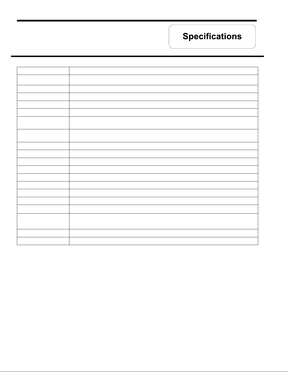
Power supply Dedicated 120 VAC, 60 Hz, 15A, GFI
Gas Supply
Approved Gas Type Natural or Propane. Unit must match gas type supplied.
Gas Pressure (Nat & L.P.) 14.0" W.C. maximum static, 4.5" W.C. minimum running (recommend 7.0" W.C. min running)
Venting System Power vent, balanced direct vent or unbalanced direct vent. See vent tables on page 7
Approved Vent Materials PVC, CPVC or ABS
Minimum Clearance
for Servicing
Maximum Water Supply
Pressure
Thermostat Sensor 11,900 Ohms @ 70°F, ECO opens @ 201°F Max., ECO close @ 100°F Min.
Temperature Dial Min. set point 5400-6600 ohms, Max set point 0-50 ohms.
Thermostat Board Max temp 180°F, Min temp 91°F, 24VAC, 60Hz max.
Ignition Module See page 9
Transformer 120VAC primary, 24VAC secondary, 40VA.
Hot Surface Igniter 120VAC, 30-120 ohms @ room temperature.
Flame Sensor Output Minimum 1 micro amp, Typical range 4 to 7 micro amps.
Gas Valve Negative regulation, 24 VAC, ½" PSI max., 4.5" W.C. Minimum running inlet.
Minimum 1" NPT for UHE100T399, all others ¾" NPT
(schedule 40 black iron pipe recommended)
18" from top, 24" from front, 4" sides and rear.
150 PSI
LAARS Heating Systems
Vent Safety Switch Normally closed, opens @ 350°F, manual reset.
Blocked Vent Pressure
Switch
Blower 120VAC, 60Hz, .6-1 amps, 6400 RPM.
Combustion Levels CO2: 10-11%, CO: less then 0.04 percent (400 PPM) air free
24VAC, normally closed, opens when pressure increases to +2.70 W.C.
6
Page 7
U.H.E Service Manual
Page 7
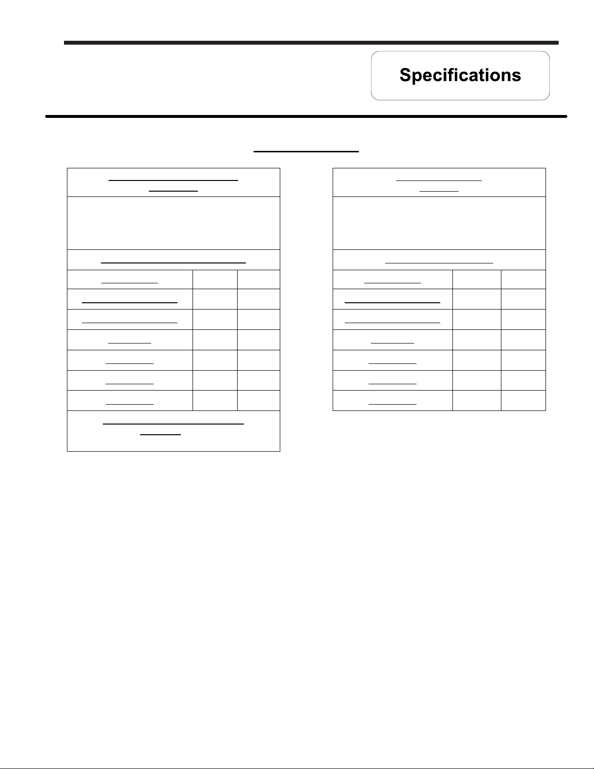
Vent Tables
Balanced Direct Vent Systems
PVC, CPVC
Total length of intake piping and exhaust piping
added together must not exceed “Maximum
Combined Length”
Shown below
Maximum Combined Length (feet)
Model Number 3"
UHE60T125, UHE100T150 120'
UHE60T150, UHE100T199
UHE60T199 80' 130'
UHE100T250
UHE100T300
UHE100T399 50' 100'
Unbalanced Direct Vent Systems
Air intake CAN NOT exceed exhaust
by more than 30 feet
100'
80'
60'
4"
170'
150'
130'
110'
Power Vented Systems
PVC, CPVC
Total length of exhaust piping must not exceed
“Maximum Vent Length”
Shown below
Maximum Vent Length (feet)
Model Number 3"
UHE60T125, UHE100T150 120'
UHE60T150, UHE100T199
UHE60T199
UHE100T250 80' 130'
UHE100T300
UHE100T399 50' 100'
100'
80'
60'
4"
170'
150'
130'
110'
Notes:
1) Multiply the total number of 90° elbows (intake and exhaust) by 5 feet. Do not include the
termination fittings or 3" condensate elbow.
2) Multiply the total number of 45° elbows (intake and exhaust) by 2 ½ feet.
3) Add this to the total length of straight pipe - intake and exhaust.
4) The sum total of all elbows and straight pipe - intake and exhaust must not exceed maximum
lengths from tables above.
Example: UHE100T199
A 3" Balanced Direct vent system has 30 feet of straight exhaust pipe and 30 feet of straight intake pipe.
It has 3- 90° elbows in the exhaust and 3- 90° elbows in the intake. It has 1- 45° elbow in the exhaust and
1- 45° elbow in the intake.
Therefore:
6- 90° elbows x 5 feet = 30 feet.
2- 45° elbows x 2½ feet = 5 feet.
60 feet of straight pipe + 30 feet + 5 feet = 95 feet.
System is within “Maximum Combined Length” from table above.
7
Page 8
Page 8
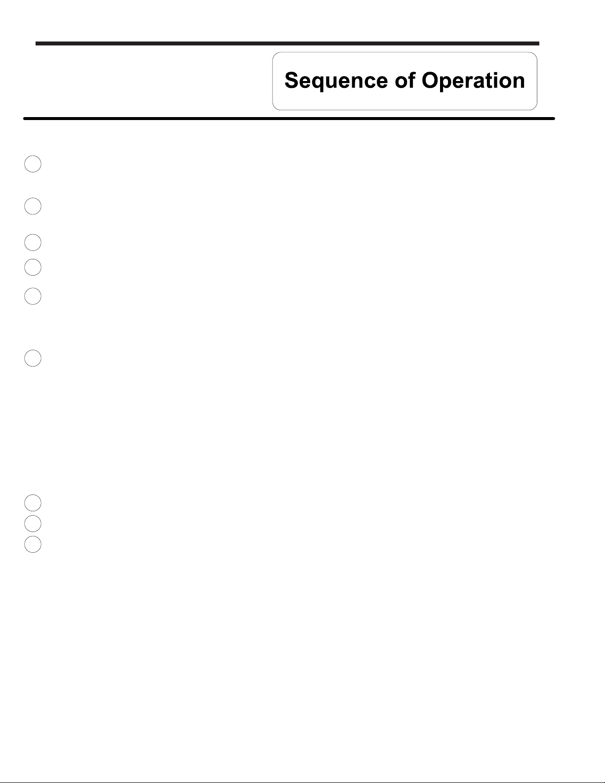
1
Thermostat calls for heat.
LAARS Heating Systems
Prior to energizing blower, ignition module checks to make sure the vent temperature switch is in the normally closed
position. If the vent temperature switch is open, the control waits indefinitely for the temperature switch to close.
2
Blower energizes, pressure switch contacts are normally closed. If the pressure switch contacts are open, blower operates for up to
5 minutes waiting for contacts to close, then blower stops and flashes red PURGE LED indicating lock-out condition.
3
Blower pre-purge period (5 seconds) indicated by PURGE LED on the module
4
Igniter warm up (18 seconds), indicated by the IGNITER LED on the module. Note: The blocked vent pressure switch
must be in the normally closed position for the ignition cycle to start.
5
Trial for Ignition (4 seconds, 3 trials).
a) Flame establishing period (2.5 seconds), gas valve and igniter on, indicated by the IGNITER and VALVE LED on the
module.
b) Burner on, flame proving period (1.5 seconds, looking for minimum of 1 micro amps), indicated by the FLAME &
VALVE LED on the module.
Steady state operation.
6
Ignition module monitors:
- Thermostat circuit.
- When thermostat opens, gas valve is shut down and post purge begins.
- Safety circuit.
- If vent temperature switch opens, gas valve is shut down, system will post purge and wait for switch to close
before attempting re-ignition.
- If the blocked vent pressure switch opens, indicating a blocked exhaust vent condition, the gas valve is shut
down, blower shuts down for 30 seconds and is re-energized and system attempts re-ignition if the pressure
switch is closed. Blower operates for 5 minutes to wait for pressure switch to close, then shuts off with purge
light flashing (lock-out). Will restart in 1 hour to attempt to close the switch and restart ignition sequence.
- Flame sensor circuit.
- If flame is lost, gas valve is shut down, system will post purge and system attempts re-ignition.
7
Thermostat satisfied.
8
Burner off.
9
Blower post purge (15 seconds).
8
Page 9
U.H.E Service Manual
Lockout Conditions
Lockout conditions:
The system will go into lock out mode for the following reasons:
Blocked vent pressure switch contacts open:
Check for obstruction in exhaust pipe and vent terminal.
Check for blocked condensate trap or drain line. In cold climates, make sure drain is not frozen.
No ignition after 3 attempts:
a) Check inlet and outlet gas pressures (pressure taps located on top of gas valve).
b) Igniter resistance too high (lower resistance preferred < 150 ohms).
c) Misadjusted veturi screw (should be 6.5 turns out from bottom).
d) Flame sense microamp not present (1.0 microamps minimum, should be 5 microamps or more). If burner lit,
check flame rod for deposits.
e) Check burner tube condition. Refer to section UHE-III for Burner Tube Inspection and Replacement.
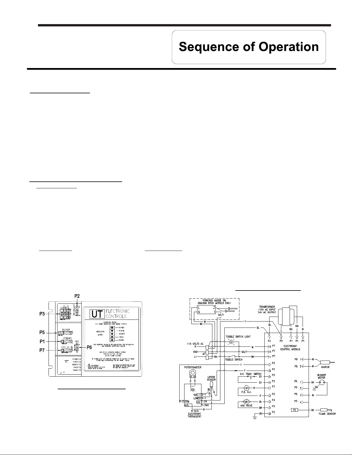
Ignition Module Specifications
Control Functions:
- Ignition & heating functions in response to thermostat.
- Hot surface ignition using a microprocessor to control timing, flame sensing using flame rectification & ignition
retries.
- Monitoring of system pressure switches and limit switches.
- Control of gas valve, inducer motor, and hot surface igniter element based on thermostat demand and status of
safety inputs.
- Diagnostic indicators to provide information on power to control and control status.
- Non-interchangeable polarized plug-in connectors for all interconnections.
Page 9
Control Inputs:
- Thermostat call for heat.
- Blocked vent pressure switch
(normally closed)
- Flame sensing.
- Low voltage supply.
- Line voltage supply.
IGNITION MODULE
Control Outputs:
- Inducer motor
- Hot surface igniter
- Gas valve
- Status indicator LEDs
Power - Green
Purge - Red
Igniter - Red
Valve - Red
Flame - Red
WIRING DIAGRAM
9
Page 10
Page 10
LAARS Heating Systems
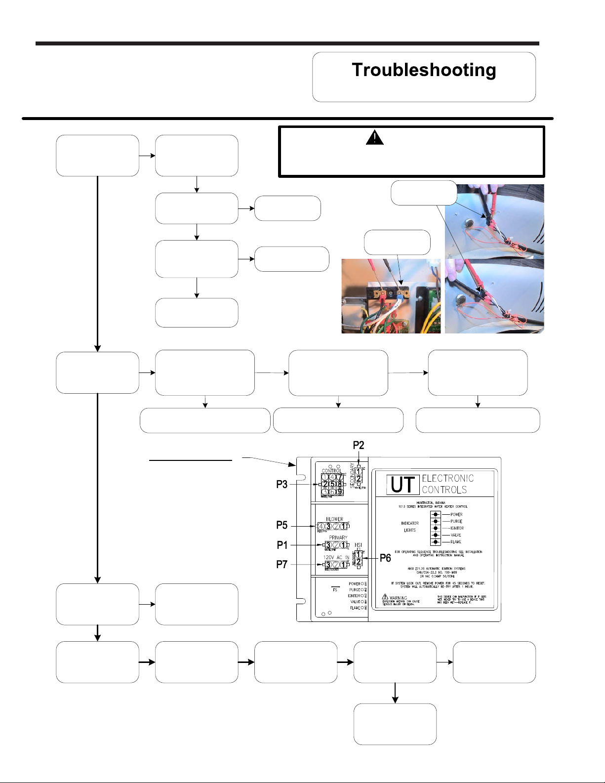
System Observation
Is front panel power
switch light on,
indicating power?
Y
Is ignition module
power light on?
Y
Position front panel
N
N
power switch to
“ON” position.
Is there 120VAC
across switch?
(see photo at right)
N
Is there 120VAC
across terminal block?
(see photo at right)
N
Determine power source
problem and correct.
Refer to ignition module
illustration, is there 120VAC
going to module at locations
P7(1) and P7(3)?
Replace ignition module.
(see page 24)
WARNING
120 volt potential exposure. Use caution
making voltage checks to avoid personal injury.
Power Switch
Light burned out,
Y
replace switch.
Terminal Block
Repair/replace wire
Y
harness to switch.
Y
N
Refer to ignition module
illustration, is there 120VAC
between P1(1) and P1(3)?
N
Replace ignition module.
(see page 24)
Y
Refer to ignition module
illustration, is there 24VAC
going to module at locations
P2(1) and P2(2)?
N
Replace transformer.
(see page 35)
Is ignition module
power and flame light
flashing?
N
Reset heater by
interrupting power.
IGNITION MODULE
Supply voltage polarity is
Y
incorrect.
Reestablish power and
Adjust thermostat to
call for heat,
tank must be cold.
Allow heater to run
through heating cycle.
Did heater complete
heating cycle and did
blower post purge?
Y
System is OK.
N
See next page
10
Page 11
U.H.E Service Manual
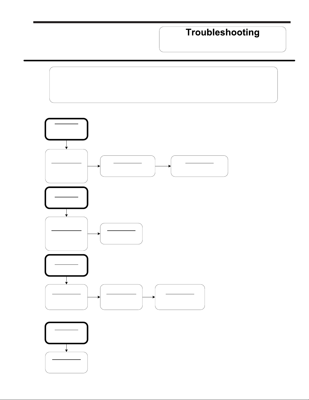
Determine failure mode by observing flashing LED status on ignition module.
* Denotes conditions that may require the water heater to be isolated from the vent
LED STATUS
Only power light
is on and water heater
will not function.
Page 11
LED status & probable cause
For models with Hot Surface Ignition
LED status and probable cause shown below.
system to determine root cause.
Probable Cause*
Exhaust pressure
switch. (see page 27)
LED STATUS
Purge light flashing.
Probable Cause*
Exhaust pressure
switch. (see page 27)
LED STATUS
Valve light flashing.
Probable Cause
Hot surface igniter.
(see page 30)
Probable Cause
Thermostat circuit.
(see page 12)
Probable Cause
Blower.
(see page 25)
Probable Cause*
Combustion system.
(see page 18)
Probable Cause
Vent safety switch.
(see page 36)
Probable Cause
Flame sensor.
(see page 32)
LED STATUS
Power & flame
light flashing.
Probable Cause
Supply voltage
polarity.
11
Page 12
Page 12
LAARS Heating Systems
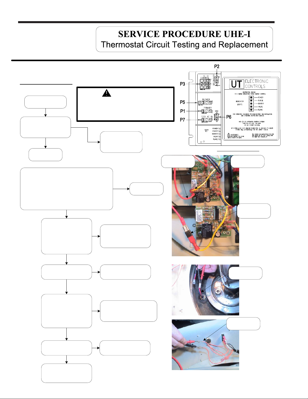
IMPORTANT NOTE: This procedure assumes a cool tank
WARNING
Rotate temperature
dial to highest setting.
120 volt potential exposure. Use
caution making voltage checks
to avoid personal injury.
Refer to ignition module
illustration, Is there 24VAC
between P3(7) and P3(8)?
N
Thermostat
not calling
Y
OK, thermostat is
calling for heat.
Red Wire
(N.O.)
IGNITION MODULE
Yellow Wire
(COM)
Disconnect YELLOW and RED wires from the
thermostat board at location N.O. and COM shown in
photo at right. Use a jumper to connect these two
Turn off power to heater.
wires together as shown in photo at right.
Restore power to heater.
Did heater cycle on?
Y
Check thermostat sensor
for proper resistance
(OHMS) across blue wires.
(See page 13)
Are readings correct?
(see photo at right)
Y
Check sensor harness
continuity.
Is there continuity?
Y
Check temperature dial for
proper resistance (OHMS)
(See Appendix B,
temperature dial resistance)
Are readings correct?
(see photo at right)
Y
N
N
N
N
Replace
thermostat sensor.
(see page 12)
Replace harness.
Replace temperature dial
(potentiometer).
(see page 16)
See page 14
Yellow & Red
wires shown
jumpered
Thermostat
Sensor
Temperature Dial
Check temperature dial
harness continuity.
Is there continuity?
Y
Replace thermostat
circuit board.
(see page 15)
N
Replace harness.
12
Page 13
U.H.E Service Manual
°F012345678 9
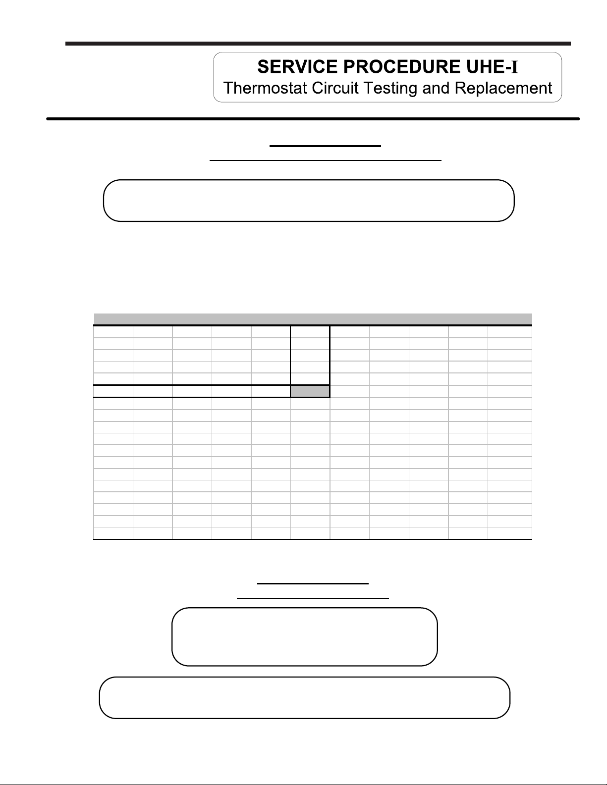
Example: If temperature of sensor is 84°F, then the resistance through the sensor would be 8449 (see shaded area).
Page 13
APPENDIX - A
Sensor Resistance at Various Temperatures
Be Careful When Making Voltage Measurements or Jumping Terminals
Not to Damage or Deform Connectors or Connector Pins.
Draw Water From The T&P Valve. Compare Temperature With
Temperature Ohms Chart Below.
NOTE: Sensor resistance increases as the temperature falls.
In Degrees F
40 26109 25400 24712 24045 23399 22771 22163 21573 21000 20445
50 19906 19383 18876 18383 17905 17440 16990 16553 16128 15715
60 15314 14925 14548 14180 13823 13477 13140 12812 12494 12185
70 11884 11592 11308 11032 10763 10502 10248 10000 9760 9526
80 9299 9078 8862 8653 8449 8250 8057 7869 7685 7507
90 7333 7165 7000 6839 6683 6531 6383 6238 6098 5961
100 5827 5697 5570 5446 5326 5208 5094 4982 4873 4767
110 4663 4562 4464 4368 4274 4183 4094 4006 3922 3839
120 3758 3679 3602 3527 3453 3382 3312 3244 3177 3112
130 3048 2986 2925 2866 2808 2752 2697 2643 2590 2538
140 2488 2439 2391 2344 2298 2253 2209 2166 2124 2083
150 2043 2004 1966 1928 1891 1856 1820 1786 1753 1720
160 1688 1656 1625 1595 1566 1537 1509 1481 1454 1427
170 1402 1376 1351 1327 1303 1280 1257 1235 1213 1191
180 1170 1150 1129 1110 1090 1071 1053 1035 1017 999
190 982 965 949 933 917 901 886 871 857 842
200 828 814 801 788 775 762 749 737 725 713
APPENDIX - B
Temperature Dial Resistance
Proper Readings Should Be 5400-6600 Ohms at Minimum Setting
And 0-50 Ohms at Maximum.
Be Careful When Making Voltage Measurements or Jumping Terminals
Not to Damage or Deform Connectors or Connector Pins.
13
Page 14
Page 14
LAARS Heating Systems
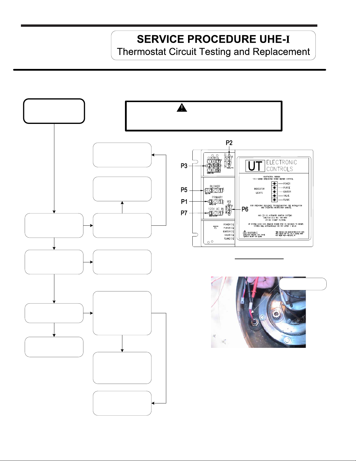
Thermostat circuit.
(continued from page 12)
Refer to ignition module
illustration, Is there 120VAC
between P1(1) and P1(3)?
Y
Refer to ignition module
illustration, Is there
22 - 27VAC between
P2(1) and P2(2)?
Y
Check AC source to
determine why there is no
N
illustration, Is there 120VAC
between P7(3) and P7(1)?
N
power.
Replace
ignition module.
(see page 34)
Y
Refer to ignition module
Replace transformer.
(see page 35)
WARNING
120 volt potential exposure. Use caution
making voltage checks to avoid personal injury.
N
IGNITION MODULE
Red Wires
(Temperature Sensor)
Refer to ignition module
illustration, Is there 24VAC
between P3(9) and P2(1).
N
Replace ignition module.
(see page 34)
Check continuity through
ECO, red wires of
Y
thermostat sensor.
Check at temperature
less than 160°F
Is there continuity?
(see photo at right)
Check wire harness
continuity. Replace
thermostat sensor or wire
harness as necessary.
(see page 17)
Replace thermostat
circuit board.
(see page 15)
Y
N
14
Page 15
U.H.E Service Manual
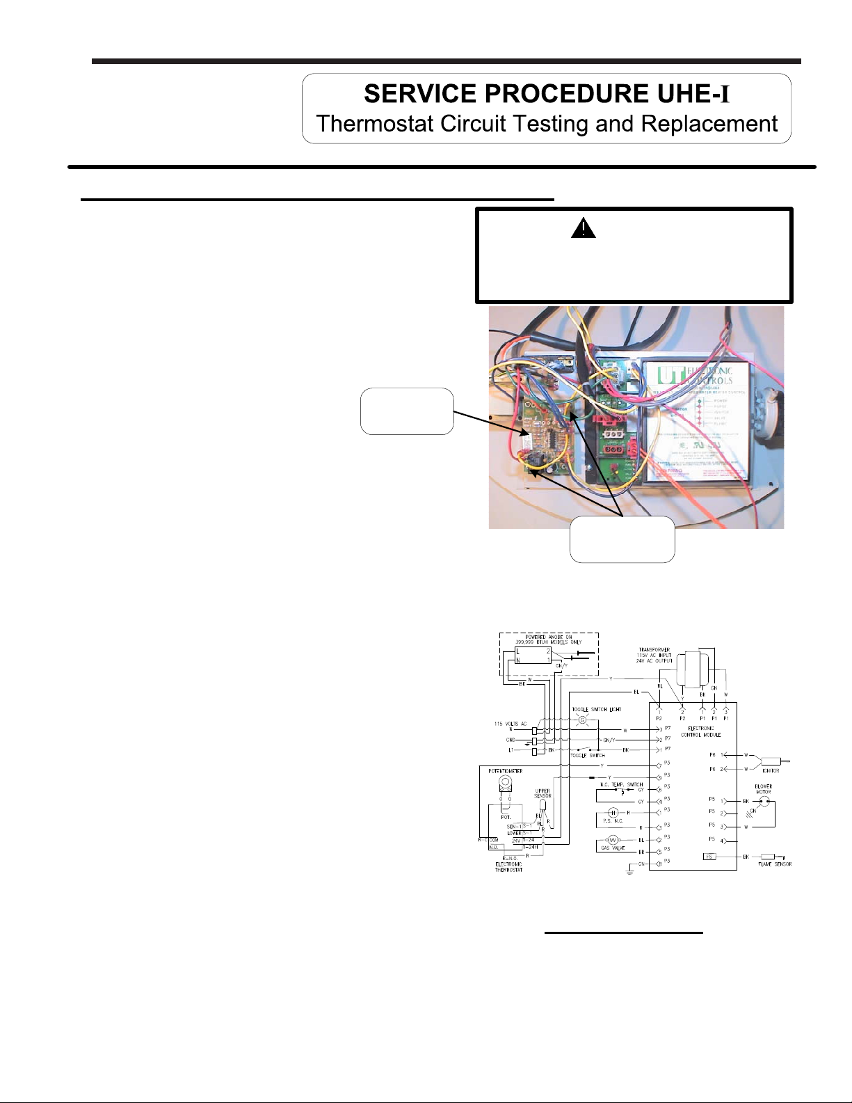
Thermostat Board Replacement Procedure
Page 15
Step 1. Position main power switch to “OFF”
Step 2. Disconnect (unplug) water heater from 120
volt power source.
Step 3. Un-latch and remove top surround cover
from top of heater.
Step 4. Locate thermostat board on control panel.
(see photo at right)
Thermostat
Board
Step 5. Carefully disconnect all wires from thermostat
board.
Note: it may be necessary to identify wires
for proper re-connection.
Step 6. Remove the two screws (Phillips head screw
driver) that secure thermostat board to
control panel.
Step 7. Install new thermostat board to control panel using
screws from step 6.
WARNING
120 volt potential exposure. Isolate the
appliance and reconfirm power is
disconnected using a multi-meter.
Mounting
screw locations
Step 8. Carefully reconnect wiring per the wire
diagram below. Reconfirm wire
connections are correct prior to putting
heater back in service
Step 9. Restore 120 volt power supply to water
heater and confirm proper operation following
the lighting instructions on the lighting
instruction label or the lighting instruction
located in the installation and operating
instruction manual.
Step 10. Replace surround cover on top of heater.
WIRING DIAGRAM
Page 16
Page 16
LAARS Heating Systems
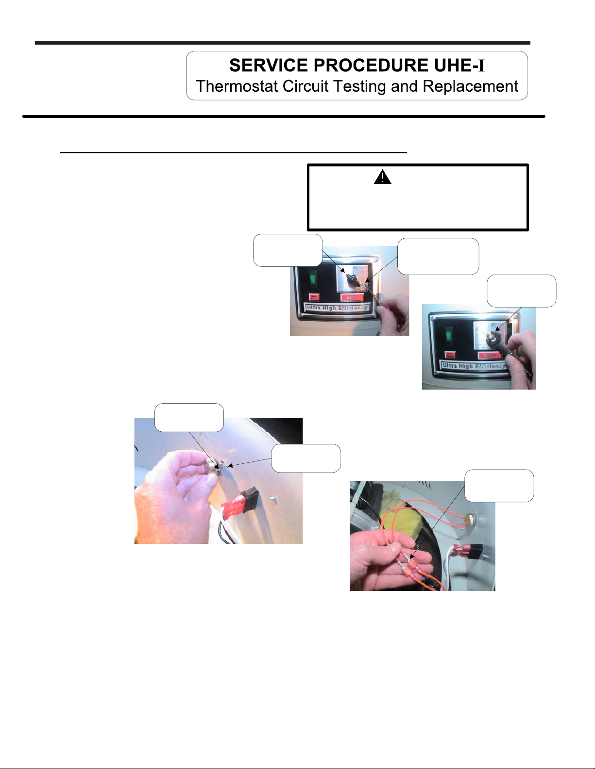
Thermostat Potentiometer Replacement Procedure
Step 1. Position main power switch to “OFF”
Step 2. Disconnect (unplug) water heater from
Step 3. Un-latch and remove top surround cover
Step 4. Loosen set screw of adjusting
Step 5. Remove retaining nut (½" wrench)
Step 6. From inside of surround area, remove potentiometer
120 volt power source.
from top of heater.
Temperature
Adjusting Knob
knob (small blade screw driver)
and remove adjusting knob
from potentiometer. (see photos at right)
and washer from potentiometer.
(see photos at right)
with gasket from side of surround. Notice how indexing
tab on potentiometer assembles into locating hole of
surround. (see photos below)
Indexing
Tab
Locating
WARNING
120 volt potential exposure. Isolate the
appliance and reconfirm power is
disconnected using a multi-meter.
Loosen set screw
with small blade
screw driver
Remove
retaining nut
Hole
Step 7. Disconnect potentiometer wire leads.
(see photo at right)
Step 8. Install new potentiometer with gasket into side of surround. Be sure to assemble with
indexing tab inserted into locating hole on side of surround (see photos above).
Step 9. Reconnect wires to potentiometer. Note: Wire leads are interchangeable with either wire.
Step 10. Restore 120 volt power supply to water heater and confirm proper operation following
the lighting instructions on the lighting instruction label or the lighting instruction located
in the installation and operating instruction manual.
Step 11. Replace surround cover on top of heater.
Potentiometer
Wire Leads
16
Page 17
U.H.E Service Manual
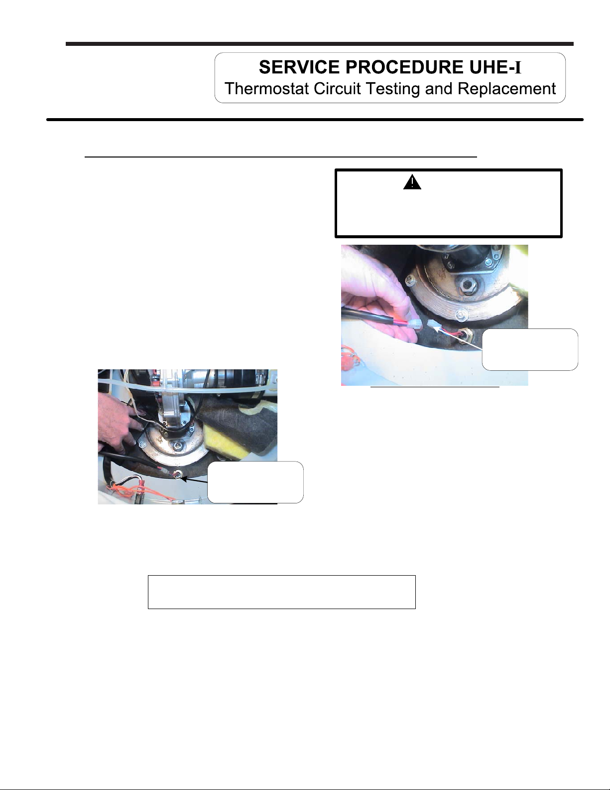
Thermostat Sensor (Thermistor) Replacement Procedure
Page 17
Step 1. Position main power switch to “OFF”
Step 2. Disconnect (unplug) water heater from
120 volt power source.
Step 3. Drain water heater down to a point below the
top of the tank.
Step 4. Un-latch and remove top surround cover
from top of heater.
Step 5. Fold back insulation just in front of burner to
expose temperature sensor (see photo below).
Step 6. Disconnect temperature sensor from
harness (see photos at right).
WARNING
120 volt potential exposure. Isolate the
appliance and reconfirm power is
disconnected using a multi-meter.
Disconnect sensor
from harness
Hot Surface Ignition Models
Insulation folded back
to expose temperature
sensor
Step 7. Remove temperature sensor (1-1/16" hex, deep well socket) from heater.
Note: Using a deep well socket will allow room inside socket
for sensor connector and wires.
Step 8. Apply thread sealing tape or applicable thread lubricant to threads of new sensor. Install new thermostat
Step 9. Fold insulation back into place. Be sure there are no wires in contact with burner.
Step 10. Restore 120 volt power supply and water supply to water heater, check and repair any
Step 11. Replace surround cover on top of heater.
sensor and Connect to wire harness from step 6.
leaks found. Confirm proper operation following the lighting instructions on the lighting
instruction label or the lighting instruction located in the installation and operating
instruction manual.
17
Page 18
Page 18
LAARS Heating Systems
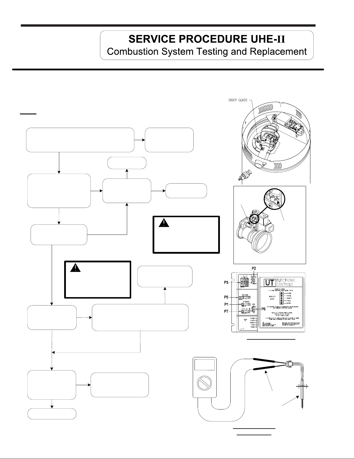
Observe burner operation through the sight glass located on the combustion insert mounting flange. Normal burner operation
should ignite smoothly, without evidence of coughing or huffing upon ignition. The burner flame should be a blue flame near the
burner surface in a uniform flame pattern. Occasional yellow or white streaks are normal.
Note: On higher input models using metal fiber mesh burner (serial
number “CK” and later) a red glow from the burner surface is normal.
Verify Minimum Gas Supply Piping Requirements of:
Minimum 1" NPT for UHE100T399, all others use ¾"
NPT. (Schedule 40 black Iron Pipe recommended).
Y
With manometer, check inlet
gas pressure. Is it stable
between 7" & 14" W.C. static?
(heater not running)
(see illustrations at right)
Y
Does inlet gas pressure
drop more than 2" W.C.
during burner ignition?
N
N
Y
Inadequately
sized regulator.
Is gas supply pressure
regulator adjustable to
maintain proper and
stable setting?
WARNING
120 volt potential
exposure. Use caution
making voltage checks to
avoid personal injury.
Do you see the igniter
glowing through burner
site glass during the
warm up period?
Y
N
Refer to ignition module illustration below,
is there 120VAC across terminals
P6(1) and P6(2)?
(Note: Igniter LED must be lit during this check).
N
N
Reconfigure gas
supply piping
Y
inlet gas pressure tap will
immediately allow gas to
Replace ignition module.
(see page 34)
Y
Adjust gas
supply regulator
WARNING
Removing screw from
flow from pressure tap.
N
Volt meter set to
OHM setting
Venturi
adjustment
Inlet gas
pressure tap
IGNITION MODULE
Is igniter resistance
less than 150 Ohms
(cold)?
(see check igniter
illustration)
Y
Proceed to next page
N
Replace
hot surface igniter.
(see page 30)
Meter probe
Hot surface
igniter
CHECK IGNITER
RESISTANCE
18
Page 19
U.H.E Service Manual
Page 19
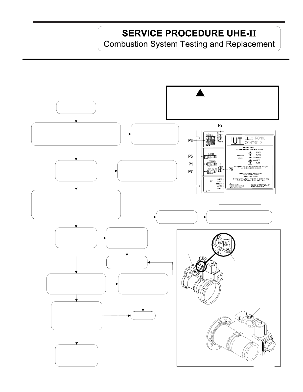
Observe burner operation through the sight glass located on the combustion insert mounting flange. Normal burner operation
should ignite smoothly, without evidence of coughing or huffing upon ignition. The burner flame should be a blue flame near the
burner surface in a uniform flame pattern. Occasional yellow or white streaks are normal.
WARNING
120 volt potential exposure. Isolate the
Continued from
previous page
appliance and reconfirm power is
disconnected using a multi-meter.
Refer to ignition module illustration below,
is there 24VAC between P3(2) and P3(5) (blue and
brown wires) during the flame establishing period?
(Note: Valve LED must be lit during this check)
Y
Can you hear or feel
gas valve energize?
Y
Turn VENTURI set screw clockwise until its
bottomed out. Turn screw counter-clockwise 6-½
turns from bottom (see illustration below). Note:
UHE100T399 models do not have a venturi screw.
The gas regulator setting should be 1 - 1 ¼ turns
out from bottom.
Y
Does burner light
smoothly, without
evidence of coughing
or huffing?
Y
N
Check for obstruction
at inlet of gas valve.
N
Call for technical
N
Replace Rectifier harness and/or
N
Is inlet free of
obstruction?
Y
support
Replace
ignition module.
(see page 34)
gas valve.
(see page 24)
Clear obstruction
adjustment
Venturi
IGNITION MODULE
N
Inspect burner tube, (see page 22)
Inlet gas
pressure tap
Does flame LED on the module
light and stay lit?
N
Check flame sensor,
Is there 1 to 5 micro amps
(min.) during 1.5 second
flame proving period?
(see page 32)
N
Replace flame sensor
(see page 32)
Y
Y
Does burner operate
normaly until thermostat is
satisfied?
Y
System OK
N
Gas valve
regulator
UHE100T399
Only
19
Page 20
Page 20
LAARS Heating Systems
WARNING
Heater components may be HOT when performing the following steps in this procedure.
Take necessary precaution to prevent personal injury.
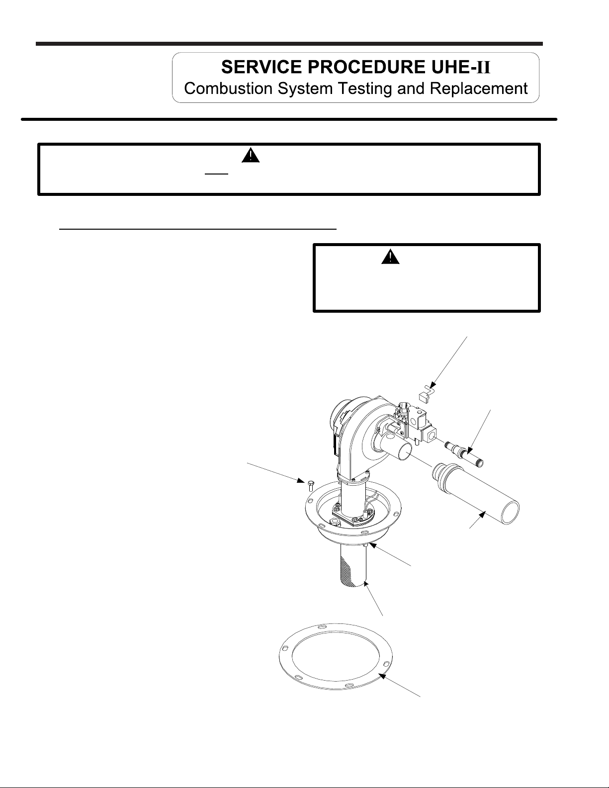
Combustion System Removal Procedure
Step 1. Position main power switch to “OFF”.
Step 2. Disconnect (unplug) water heater from
120 volt power source.
Step 3. Turn off gas supply to water heater.
Step 4. Un-latch and remove surround cover from top of
heater.
Step 5. From the gas valve, disconnect the gas
connection, PVC venting, Silicone tubing
and wire harness.
Step 6. Disconnect wire harnesses flame sensor and
Blower. Disconnect wire harness from hot surface
igniter.
Burner mounting
screw
(Total of 5)
WARNING
120 volt potential exposure. Isolate the
appliance and reconfirm power is
disconnected using a multi-meter.
Gas valve
wire harness
Gas
connection
PVC vent
connection
Step 7. Remove the 5 bolts (½" socket)
holding the burner mounting insert
in place.
Step 8. Carefully remove combustion assembly
with gasket from water heater.
Step 9. See next page for combustion system installation procedure.
Burner mounting
insert
Burner tube
Burner mounting
insert gasket
20
Page 21
U.H.E Service Manual
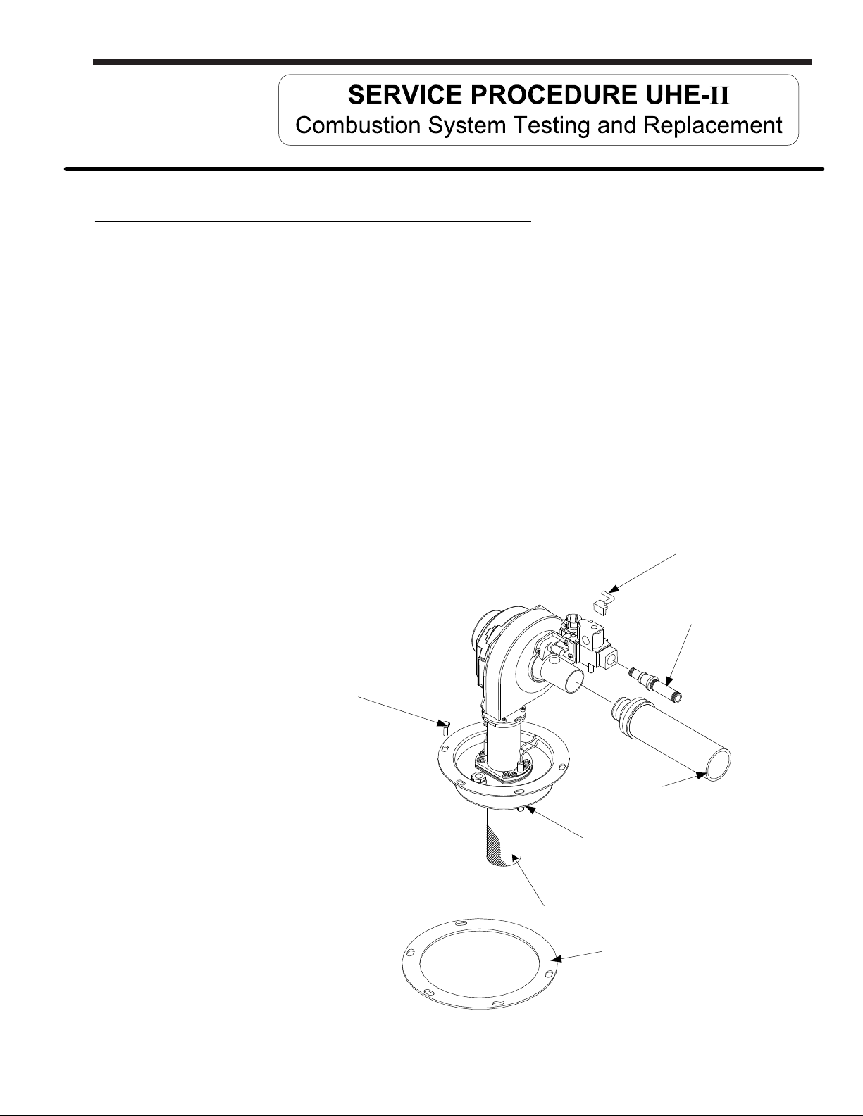
Combustion System Replacement Procedure
Step 1. Fully inspect burner mounting insert gasket for the following:
a) Tears d) Dirt or debris
b) Missing material e) Other imperfections that would inhibit proper seal
c) Cracks
If gasket is NOT affected by any of the above, gasket replacement is not required.
Step 2. Install combustion assembly using new gasket or fully inspected gasket from step 1.
Secure combustion assembly at the burner mounting insert using screws from step 6
on previous page. Tighten screws evenly.
Step 3. Reconnect wire harnesses to hot surface igniter, flame sensor, blower and gas valve.
Page 21
Step 4. Reconnect PVC venting, gas supply and silicone tubing to gas valve. Turn on gas
supply to heater and check for gas leaks, repair any gas leaks found.
Step 5. Restore 120 volt power supply to water heater and confirm proper operation following
the lighting instructions on the lighting instruction label or the lighting instruction located
in the installation and operating instruction manual.
Step 6. Replace surround cover on top of water heater.
Burner mounting
screw
(Total of 5)
PVC vent
connection
Burner mounting
insert
Gas valve
wire harness
Gas
connection
Burner tube
Burner mounting
insert gasket
21
Page 22
Page 22
LAARS Heating Systems
WARNING
Heater components may be HOT when performing the following steps in this procedure.
Take necessary precaution to prevent personal injury.
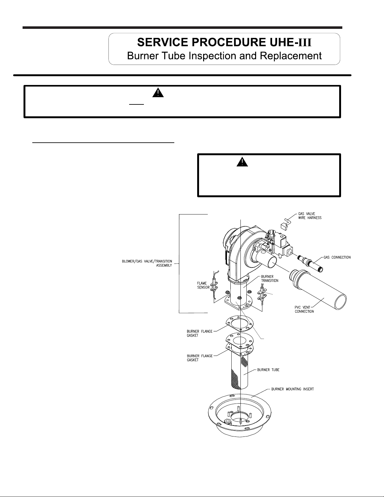
Burner Tube Removal Procedure
Step 1. Position main power switch to “OFF”.
Step 2. Disconnect (unplug) water heater from
120 volt power source.
Step 3. Turn off gas supply to water heater.
Step 4. Un-latch & remove surround cover from top of
heater.
Step 5. From the gas valve, disconnect
the gas connection, PVC venting,
wire harness and silicone tubing.
Step 6. Disconnect wire harness from
blower assembly.
Step 7. Remove the two screws holding
each the hot surface igniter and
flame sensor in place (long reach
magnetic Phillips screw driver).
Carefully remove hot surface igniter
and flame sensor from combustion
assembly.
WARNING
120 volt potential exposure. Isolate the
appliance and reconfirm power is
disconnected using a multi-meter.
HOT SURFACE
IGNITER/SPARK
ROD
BURNER TRANSITION
MOUNTING NUTS
Step 8. Remove the 4 nuts (7/16" wrench) holding
the burner transition in place. Lift the blower/gas
valve transition assembly from burner mounting
insert, remove gasket and set aside.
Step 9. Remove burner tube from burner
mounting insert. See next page for
burner tube inspection procedure.
22
Page 23
U.H.E Service Manual
WARNING
Heater components may be HOT when performing the following steps in this procedure.
Take necessary precaution to prevent personal injury.
Burner Tube Inspection
Page 23
Step 1. Inspect burner tube as follows (BSI ceramic fiber mesh burner, water heaters prior to
Step 2. If burner tube is affected by any of the above, replacement is required. Refer to burner
serial number “CK”) :
a) Visually inspect ceramic fiber mesh, mesh should be uniform in appearance without large
gaps, tears or fraying. Mesh should have uniform pattern allowing for unrestricted gas
flow.
b) Gently squeeze burner tube, Burner tube should feel firm without any soft areas
around the sides or at the bottom.
c) Visually inspect inside burner tube, Burner tube should be intact with no areas of
deterioration. Ports should be free of any debris.
Inspect burner tube as follows (Acotech metal fiber mesh burner, water heaters with
“CK” serial number or later).
a) Outer fiber mesh should be uniform with no tears or deterioration.
tube replacement procedure below.
Burner Tube Replacement Procedure
Note: New metal fiber mesh burner (Acotech) is the replacement burner for the BSI ceramic fiber sock burner. The length
of burner will not be the same as the previous BSI burner. Provide the model and serial number for the correct replacement
burner.
Step 1. Fully inspect burner flange gaskets, igniter and flame sensor gaskets for the following:
a) Tears d) Dirt or debris
b) Missing material e) Other imperfections that would inhibit proper seal
c) Cracks
If gaskets are NOT affected by any of the above, gasket replacement is not required.
Step 2. Install burner tube with gaskets into burner mounting insert. Be sure gasket surfaces are free
of debris.
Step 3. Reconnect the blower/gas valve/transition assembly to burner mounting insert. Secure using
nuts from step 8 on previous page.
Step 4. Carefully reinstall flame sensor with gasket and hot surface igniter with gasket and secure with
screws from step 7 on previous page. Reconnect wire harnesses to sensor and igniter.
Step 5. Reconnect wire harnesses to blower motor and to gas valve.
Step 6. Reconnect PVC venting, gas supply and silicone tubing to gas valve. Turn on gas to heater
and check for gas leaks, repair any gas leaks found.
Step 7. Restore 120 volt power supply to water heater and confirm proper operation following the
lighting instructions on the lighting instruction label or the lighting instruction located in the
installation and operating instruction manual.
Step 8. Replace surround cover on top of water heater.
23
Page 24
Page 24
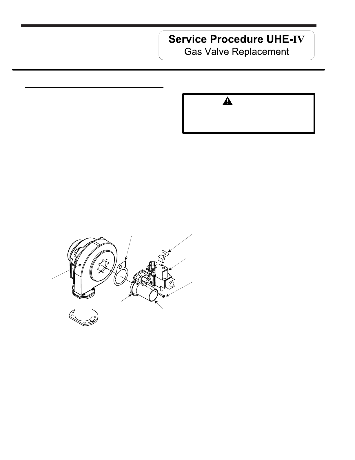
Gas Valve Replacement Procedure
Step 1. Position main power switch to “OFF”.
Step 2. Disconnect (unplug) water heater from
120 volt power source.
Step 3. Turn off gas supply to water heater.
LAARS Heating Systems
WARNING
120 volt potential exposure. Isolate the
appliance and reconfirm power is
disconnected using a multi-meter.
Step 4. Un-latch & remove surround cover from top of
Step 5. From the gas valve, disconnect
Step 6. Remove the 2 gas valve mounting screws (Torx bit) located at the
Step 7. Remove any residual gasket material from blower and venturi mounting flange.
heater.
the gas connection, PVC venting,
wire harness and silicone tubing.
11:00 O-clock & 5:00 O-clock position on the venturi mounting flange
and remove gas valve from water heater.
Blower / gas valve
gasket
Blower
Venturi
mounting flange
Venturi inlet
Gas valve
wire harness
Gas valve
assembly
Gas valve
mounting screws
(2 places)
Step 8. Install new gas valve with new gasket provided. Secure gas valve in place using
screws from step 6.
Step 9. Reconnect PVC venting, gas supply, silicone tubing & wire harness to gas valve. Turn
on gas supply to heater and check for gas leaks, repair any gas leaks found.
Step 10. Restore 120 volt power supply to water heater and confirm proper operation following
the lighting instructions on the lighting instruction label or the lighting instruction located
in the installation and operating instruction manual.
Step 11. Replace surround cover on top of
water heater.
24
Page 25
U.H.E Service Manual
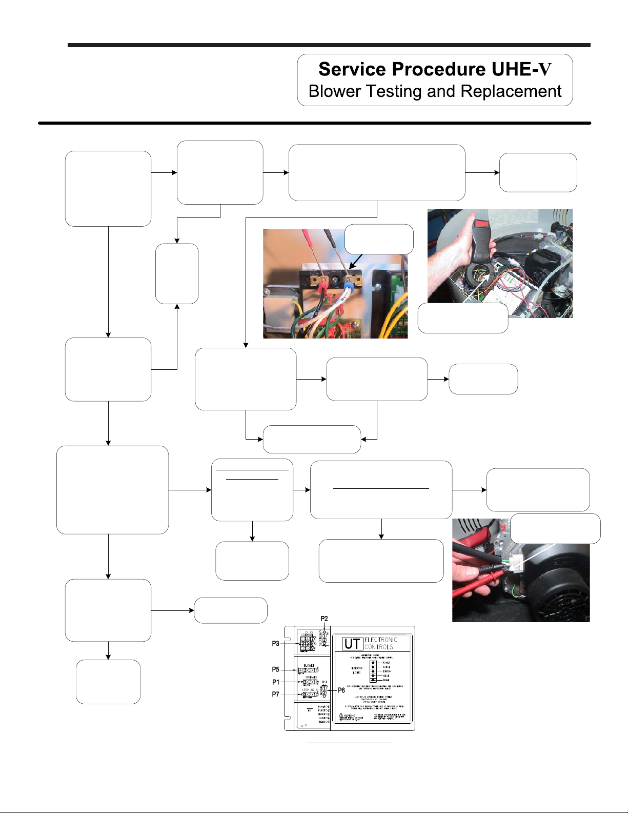
Y
Does blower
energize?
Is there 120VAC
across the white and
black wires at the
terminal block ?
(see photo at right)
N
Y
Refer to ignition module/control board
illustration. Is there 120VAC between P5(1) and
P5(3)?
Y
Page 25
N
Replace
ignition module/
control board.
N
Is there 120VAC
across the white and
black wires at the
terminal block ?
Y
Refer to ignition module/
control board illustration.
Is there 120VAC between
P5(1) and P5(3)?
Y
Determine
power
source
problem
and
correct
N
Check amp draw through
BLACK wire lead of blower
motor. Is there .6 to 3.0
amps?
Hot Surface Ignition
N
Models ONLY:
Refer to ignition
module, is there 24
VAC between P3(7)
and ground?
Thermostat not
calling for heat.
(see page 12)
Y
N
Replace blower.
(see “Blower Replacement
Procedure”)
Y
N
120VAC check at
Terminal Block
Black wire leading to
blower motor looped
through amprobe.
Is Blower wheel secured to
blower motor shaft?
N
Hot Surface Ignition Models:
Are safety circuits in normal position?
N
Correct safety circuit problem per
safety circuit trace
(see page 27).
Y
Call technical
support.
Y
Replace ignition module/
control board.
Checking for 120VAC
(Black & White Wires)
Is there 120VAC
across the white and
black wires at the
blower?
(see photo at right)
Y
Replace blower.
(see page 25)
N
Repair/replace
wire harness.
IGNITION MODULE
25
Page 26
Page 26
LAARS Heating Systems
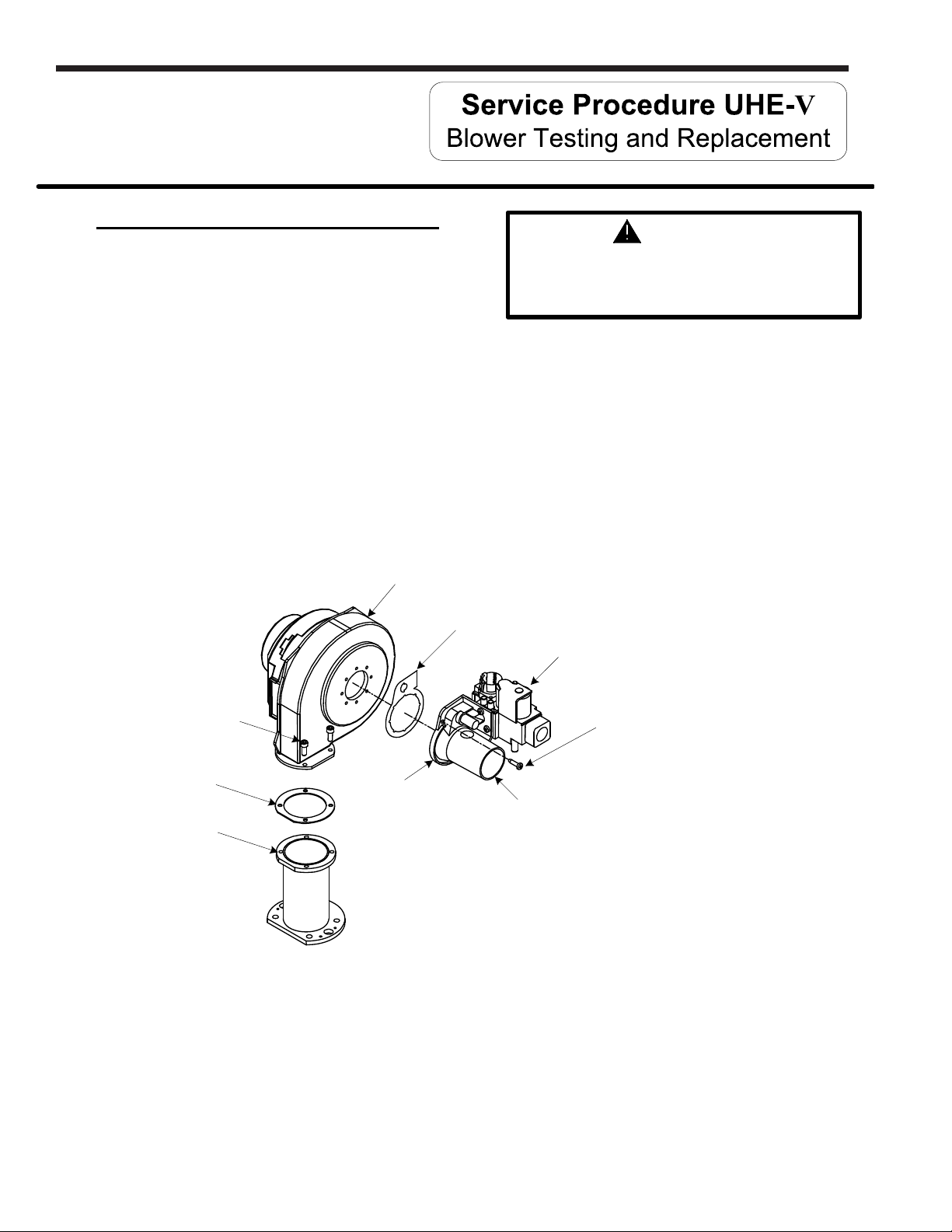
Blower Replacement Procedure
WARNING
Step 1. Position main power switch to “OFF”.
Step 2. Disconnect (unplug) water heater from
120 volt power source.
Step 3. Turn off gas supply to water heater.
Step 4. Un-latch & remove surround cover from top of
heater.
Step 5. Disconnect wire harness from blower.
Step 6. Disconnect intake vent and gas supply from gas valve assembly.
Step 7. Remove the 2 gas valve mounting screws (Torx bit) located at the
11:00 O-clock & 5:00 O-clock position on the venturi mounting flange.
Step 8. Remove The 4 blower flange mounting screws (5/32 Allen wrench) and remove blower
from transition flange.
Blower
Blower / gas valve
120 volt potential exposure. Isolate the
appliance and reconfirm power is
disconnected using a multi-meter.
gasket
Gas valve
assembly
Blower flange
mounting screws
Blower / transition
gasket
Transition
flange
Step 12. Reconnect intake vent and
gas line to gas valve assembly and
check for gas leaks repair any leaks found.
Step 13. Reconnect wire harness to blower assembly, restore 120 volt power supply & Gas supply
to water heater and confirm proper operation following the lighting instructions on the
lighting instruction label or the lighting instructions located in the installation and operating
instruction manual.
Step 14. Replace surround cover on top of
water heater.
Venturi
mounting flange
Venturi inlet
Step 9. Remove any residual gasket material
from venturi mounting flange and transition flange.
Step 10. Install new blower with new gasket
provided. Secure blower in place using
screws from step 8.
Step 11. Reconnect gas valve assembly to blower
with new gasket provided. Secure gas
valve in place using screws from step 7.
Gas valve
mounting screws
2 places.
26
Page 27
U.H.E Service Manual
Exhaust Pressure Switch Testing and Replacement
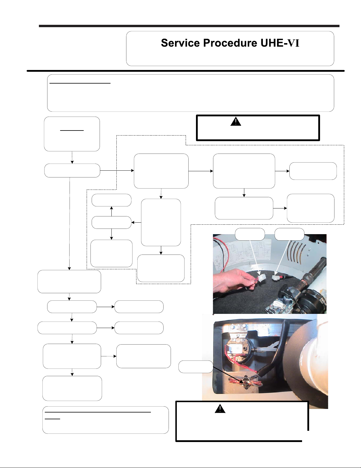
Sequence of operation:
The blocked vent pressure switch monitors the pressure in the exhaust tube. The switch contacts are normally closed and will
not open unless there is a blockage in the exhaust venting or terminal (snow, ice, debris). If the blocked vent pressure switch
contacts open after the thermostat initiates the blower, the blower will remain on for to 5 minutes waiting for the contacts to close.
If the contacts remain open, the blower will stop and the PURGE LED will flash for hot surface ignition models.
WARNING
LED Status
Only power LED is on, or
Purge LED flashing.
Safety Circuit Trace
120 volt potential exposure. Use caution
making voltage checks to avoid personal injury.
Page 27
Does blower
energize?
Y
Check PURGE LED status.
On within 5 minutes? Pressure switch is OK.
N
Flashing after 5 minutes?
Error code 29 again?
Y
N
Call technical
support.
N
Does heater
function?
Y
Verify proper
switch operation.
(see page 36)
Y
N
Call for technical
wire leads of heater side
Y
support.
Is there continuity
Through GREY
safety circuit harness?
(see photo below)
N
Depress reset
button on vent
safety switch. Is
there continuity
across high limit
switch?
(see photo below)
N
Replace vent safety
switch.
(see page 37)
Is there continuity
Y
through RED
wire leads of heater side
safety circuit harness?
(see photo below)
Y
Check PURGE LED status
on ignition module,
Flashing after 45 seconds?
Control side
harness
N
Y
Heater side
Safety Circuit OK,
(see page 36)
Replace exhaust
pressure switch (see
harness
page 29)
Check blower for proper
operation (see page 25)
Is blower OK?
Y
Refer to
“Check Collector Pressure”
(see next page)
N
Correct blower problem
(see page 25)
Note: HOT SURFACE IGNITION MODELS
ONLY - The blocked vent pressure switch
must be used with the revised ignition control,
identified with a yellow label.
Reset button
WARNING
Make sure exhaust collector compartment is not
overheating (350°F) before resetting vent safety
switch. If there is evidence the collector compartment
is overheating, CALL TECHNICAL SUPPORT.
27
Page 28
Page 28
Exhaust Pressure Switch Testing and Replacement
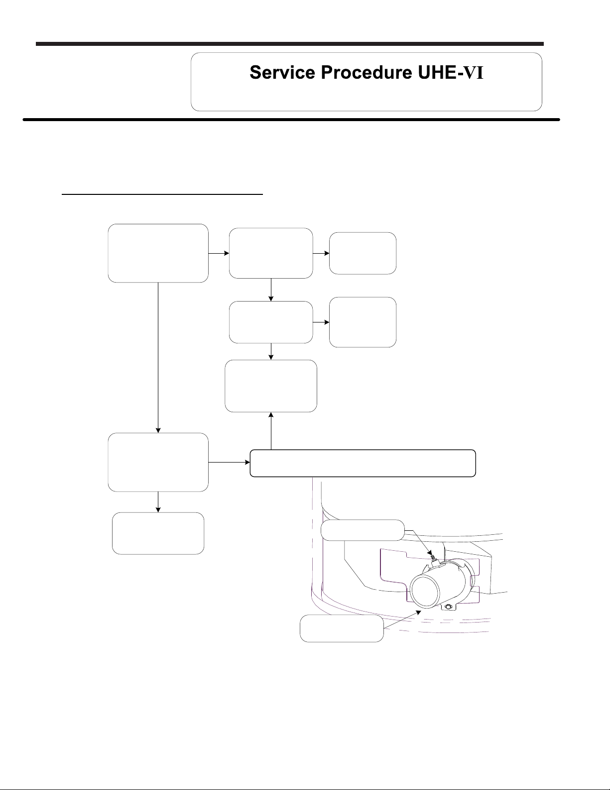
Check Exhaust Tube Pressure
LAARS Heating Systems
With monometer, take a
reading at the exhaust
tube pressure tap location.
Is value negative (-) or
slightly postitive
(see illustration below).
Y
With ohmmeter check
pressure switch for
continuity. Contacts should
be closed.
Y
Is exhaust venting
N
N
system blocked or
obstructed? Also
check condensate
elbow and drain.
Is vent system total
length compliant with
vent tables in the
instruction manual?
blocked vent switch.
Clear obstruction.
Y
Determine cause
and correct.
N
Reconfigure vent
system to be
N
compliant with
vent tables (see
Y
Replace
(see page 29)
Is pressure in exhaust tube near 2.7" w.c. or more? If so, correct
blockage (above). If exhaust pressure is low (0.40" or less), replace
“Specifications”).
pressure switch.
Pressure switch O.K.
Exhaust Tube
pressure tap location
Exhaust tube
at bottom of heater
28
Page 29
U.H.E Service Manual
Exhaust Pressure Switch Testing and Replacement
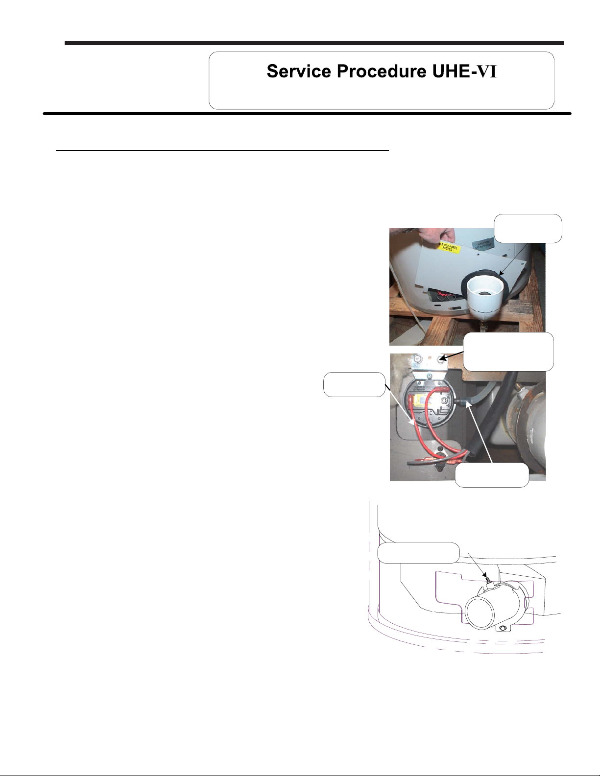
Exhaust Pressure Switch Replacement Procedure
Step 1. Position main power switch to “OFF” position.
Step 2. Loosen adhesive backed rubber escutcheon from service panel access cover
and slide escutcheon back along exhaust pipe to allow for removal of cover.
Step 3. Remove screws from service panel access cover
(¼" nut driver) and remove cover from heater.
(see photos at right)
Step 4. Disconnect silicone tubing and wire leads from
pressure switch. (see photos at right)
Page 29
Rubber
escutcheon
Step 5. Remove pressure switch mounting screws
(5/16" wrench) and remove pressure switch.
Step 6. Assemble new pressure switch to heater using
screws from step 5.
Step 7. Reconnect wire leads. Note: wire leads are
interchangeable with either terminal.
Step 8. Reconnect silicone tubing to pressure switch
as follows:
a) Exhaust pipe tubing connects to
single tap located on switch
Step 9. Restore 120 volt power supply to water heater
and confirm proper operation following the
lighting instructions on the lighting instruction
label or the lighting instructions located in the installation
and operating instruction manual.
Step 10. Reinstall service panel access cover and
rubber escutcheon.
Pressure switch
mounting screw
5/16 hex head
Wire leads
Silicone tubing
Exhaust Tube
pressure tap location
29
Page 30
Page 30
LAARS Heating Systems
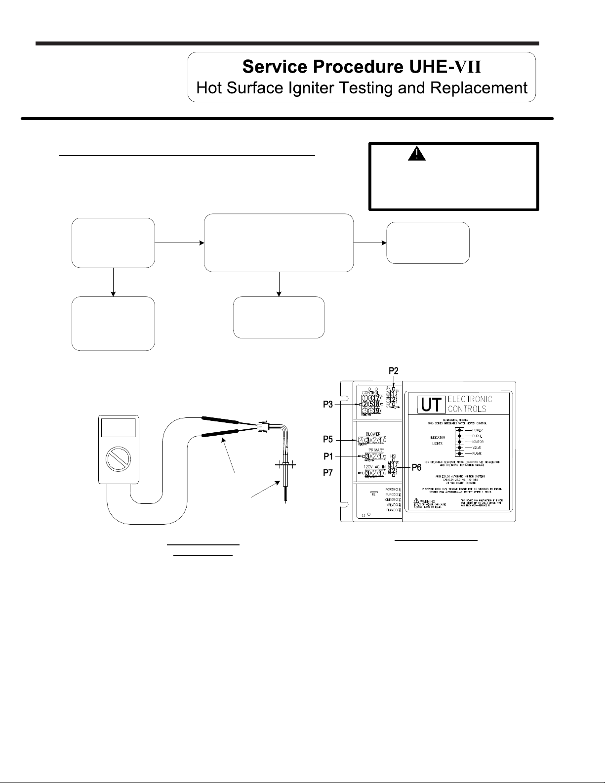
Hot surface Igniter Testing Procedure
Is igniter resistance
less than 150 Ohms
(cold)?
(see “check igniter
resistance” below)
N
Replace
hot surface igniter
(see page 30)
Volt meter set to
OHM setting
Y
Refer to ignition module illustration below,
is there 120VAC across terminals
P6(1) and P6(2)?
(Check during igniter warm up period,
indicated by the igniter LED glowing on the
ignition module).
N
Replace ignition module.
(see page 34)
WARNING
120 volt potential exposure. Use caution
making voltage checks to avoid
personal injury. Igniter may be too hot
to handle, take necessary precautions
Y
Check harness
connection from igniter
to ignition module.
Meter probe
Hot surface
igniter
CHECK IGNITER
RESISTANCE
IGNITION MODULE
30
Page 31
U.H.E Service Manual
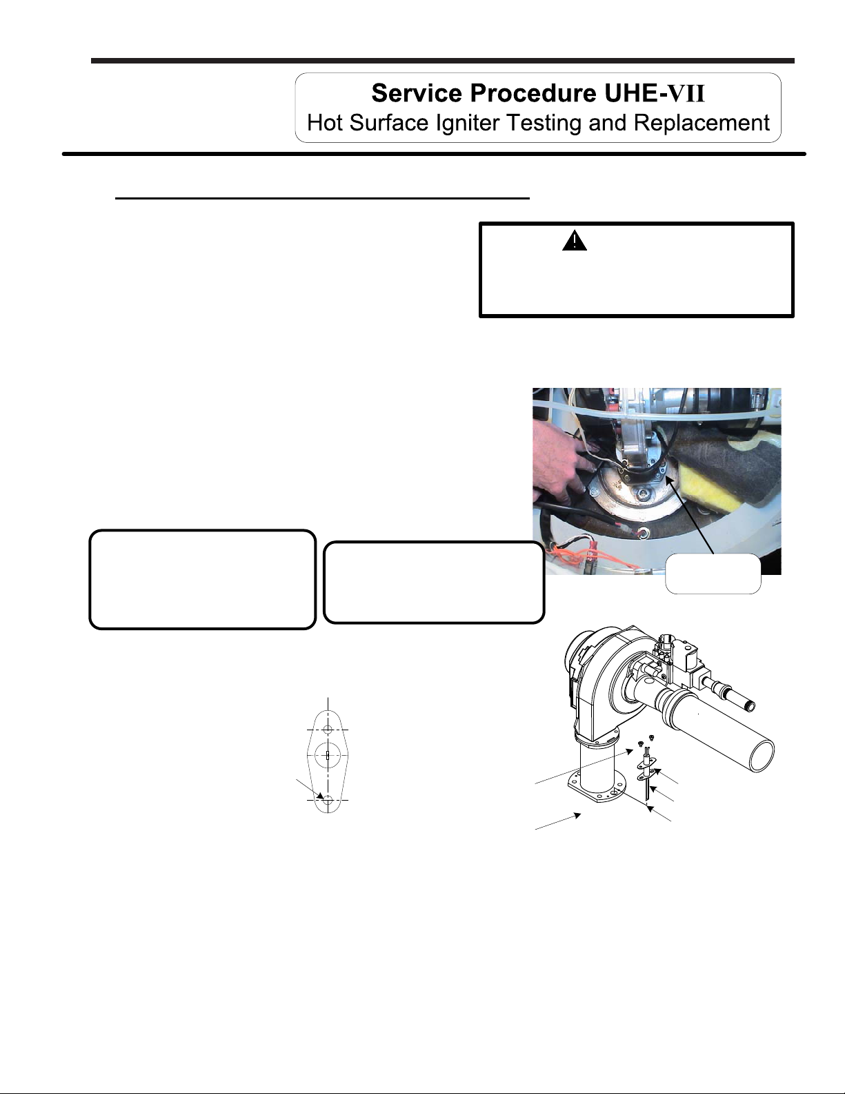
Hot surface Igniter Replacement Procedure
Page 31
Step 1. Position main power switch to “OFF”
Step 2. Disconnect (unplug) water heater
from 120 volt power source.
Step 3. Un-latch & remove surround cover
from top of heater.
Step 4. Fold back insulation in front of combustion assembly to expose hot surface igniter.
(see photo at right)
Step 5. Disconnect igniter wire leads from ignition module.
Step 6. Remove the 2 igniter mounting screws (magnetic
tip, long reach Phillips screw driver) and remove
igniter and gasket from transition base flange.
Step 7. Remove any residual gasket material from
transition base flange.
120 volt potential exposure. Isolate the
appliance and reconfirm power is
disconnected using a multi-meter.
Note:
New replacement igniter will
not have a shield over element.
Handle carefully to prevent
breakage.
Note:
Do not handle igniter element
or allow foreign material to
come in contact with element.
WARNING
Hot Surface
Igniter
Step 8. Install new igniter with new gasket provided using
screws from step 5. Arrange igniter flange with offcenter hole towards front of heater.
Off-center
mounting hole
Heater front
Step 9. Reconnect igniter wire harness.
Step 10. Fold insulation back into place. Be sure no wires are in contact with burner flange.
Step 11. Restore 120 volt power supply to water heater and confirm proper operation following the
lighting instructions on the lighting instruction label or the lighting instructions located in
the installation and operating instruction manual.
Step 12. Replace surround cover on top of
water heater.
Igniter mounting
screws
Transition
base flange
Igniter flange
Igniter gasket
Igniter filament
31
Page 32
Page 32
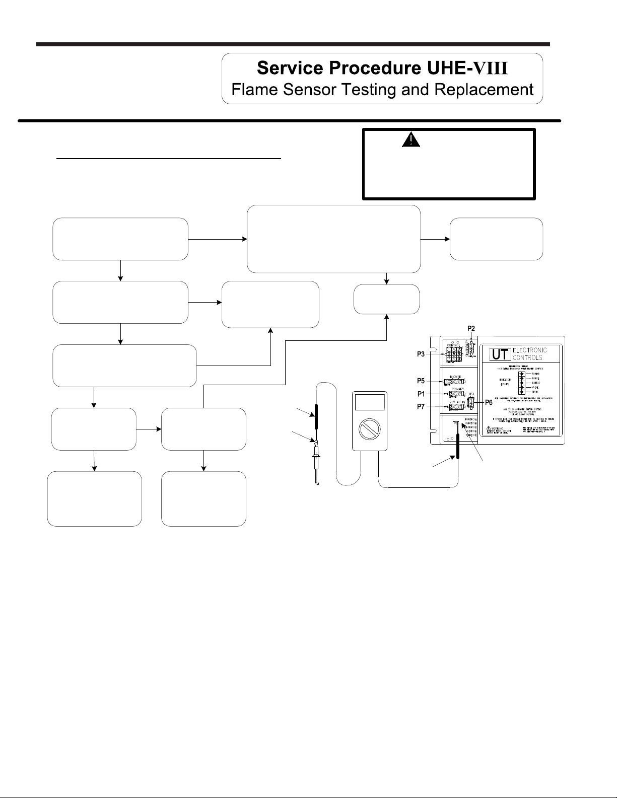
Flame Sensor Testing Procedure
LAARS Heating Systems
WARNING
120 volt potential exposure. Use caution
making voltage checks to avoid
personal injury. Flame sensor may be
too hot to handle, take necessary
precautions
Refer to illustration below, is there
a minimum of 1 micro amp during
1.5 second flame proving period?
N
With flame sensor Disconnected
from ignition module, check
continuity to ground.
Is there continuity to ground?
N
Remove flame sensor from water heater.
Check continuity from tip of flame sensor
Is flame sensor free
flame sensor with emery
cloth. (see page 33)
to end of wire lead.
Is there continuity?
Y
of oxidation?
N
Clean or replace
Y
Is ceramic of flame
sensor cracked?
Replace flame sensor.
(see page 33)
Refer to ignition module/control board
Y
Y
N
illustration.(24 volts should maintain beyond the
1.5 second flame proving period.)
Is there 24 volts AC at locations P3(2) & P3(5)?
Replace flame sensor with
gasket and/or wire lead.
(see page 33)
Volt meter set to
N
Call for
technical support
Y
Flame sensing circuit OK
Micro amps setting
(µA)
N
Meter
probe
Flame
Y
sensor
terminal
Meter
probe
Flame sensor
terminal on
ignition module.
32
Page 33
U.H.E Service Manual
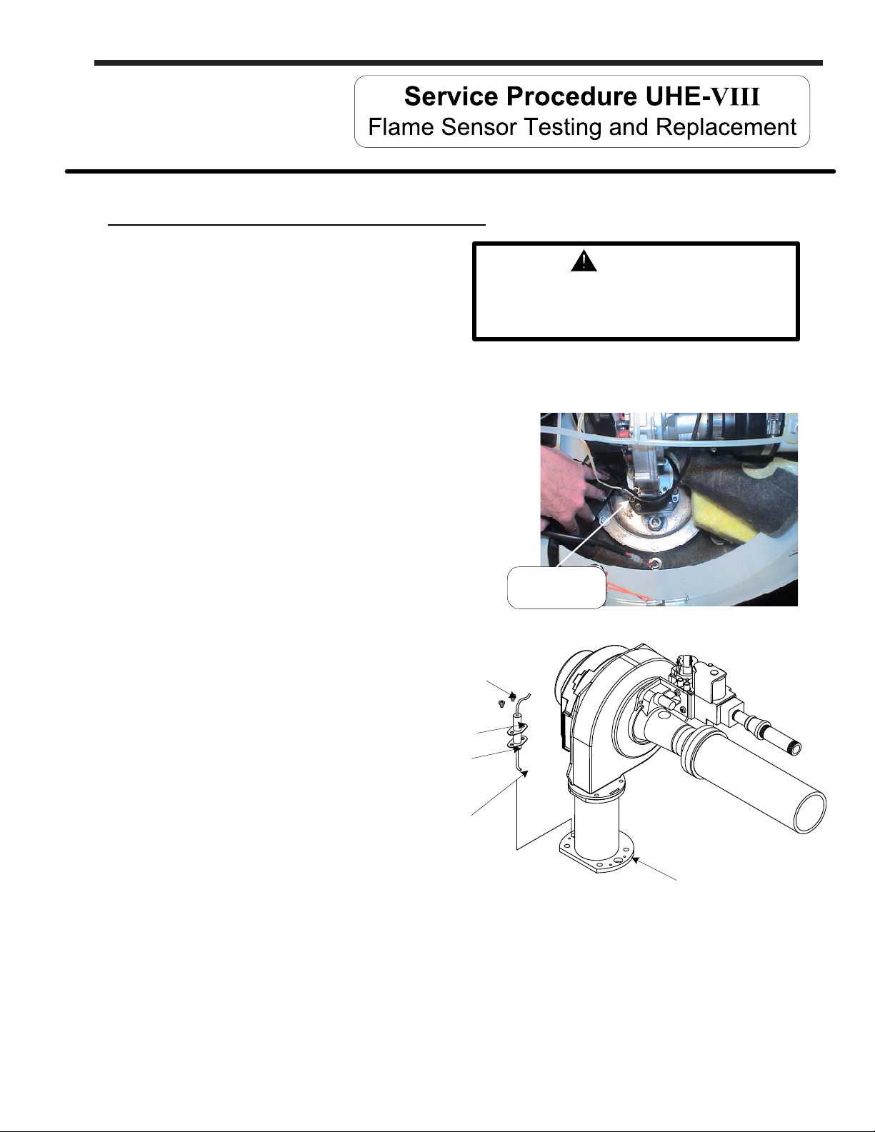
Flame Sensor Replacement Procedure
Page 33
Step 1. Position main power switch to “OFF”
Step 2. Disconnect (unplug) water heater
from 120 volt power source.
Step 3. Un-latch & remove surround cover
from top of heater.
Step 4. Fold back insulation in front of combustion assembly to expose flame sensor.
(see photo at right)
Step 5. Disconnect wire lead from flame sensor.
Step 6. Remove the 2 sensor mounting screws (magnetic
tip, long reach Phillips screw driver) and remove
flame sensor & gasket from transition base
flange.
Step 7. Remove any residual gasket material from
transition base flange.
Step 8. Install new flame sensor with new gasket provided
using screws from step 6. Arrange flame sensor with
hook towards burner.
Flame sensor
mounting screws
120 volt potential exposure. Isolate the
appliance and reconfirm power is
disconnected using a multi-meter.
Flame
sensor
WARNING
Flame sensor
Flame sensor
gasket
Arrange hook
of sensor
towards burner
Step 9. Reconnect flame sensor wire.
Step 10. Fold insulation back into place. Be sure no wires are in
contact with burner flange.
Step 11. Restore 120 volt power supply to water heater and confirm proper operation following the
lighting instructions on the lighting instruction label or the lighting instructions located in
the installation and operating instruction manual.
Step 12. Replace surround cover on top of
water heater.
base flange
Transition
33
Page 34
Page 34
LAARS Heating Systems
Ignition Module Replacement Procedure
Step 1. Position main power switch to “OFF”.
Step 2. Disconnect (Unplug) water heater
from 120 Volt power source.
Step 3. Un-latch & remove surround cover from top of water heater.
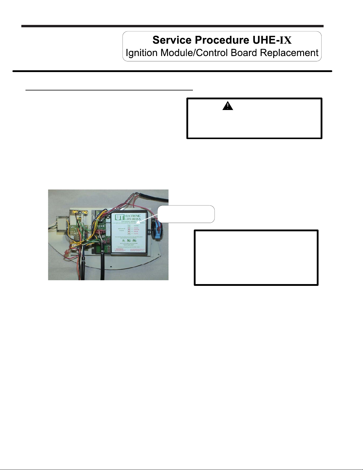
Step 4. Locate Ignition module on control panel inside surround area.
(see photo below)
Ignition Module
located on control panel
120 volt potential exposure. Isolate the
WARNING
appliance and reconfirm power is
disconnected using a multi-meter.
Note: Replacement hot surface
ignition module works on all UHE
models prior to and later than “CF”
serial numbers. Direct spark ignition
models use a different control board
(detailed in following section).
Step 5. Carefully disconnect all wire harness connection to ignition module. Connection are
non-interchangeable to insure proper reinstallation.
Step 6. Remove the 3 screws (Phillips screw driver) holding the ignition module in place and
remove ignition module from control panel.
Step 7. Install new ignition module and secure in place with screws from step 6.
Step 8. Carefully reconnect all wire harness connection to ignition module. Connection are
non-interchangeable to insure proper reinstallation.
Step 9. Restore 120 volt power supply to water heater and confirm proper operation following the
lighting instructions on the lighting instruction label or the lighting instruction located in
the installation and operating instruction manual.
Step 10. Replace surround cover on top of water heater.
34
Page 35
U.H.E Service Manual
Transformer Replacement Procedure
Page 35
Step 1. Position main power switch to “OFF”.
Step 2. Disconnect (Unplug) water heater
from 120 Volt power source.
Step 3. Un-latch & remove surround cover from
120 volt potential exposure. Isolate the
appliance and reconfirm power is
disconnected using a multi-meter.
WARNING
top of water heater.
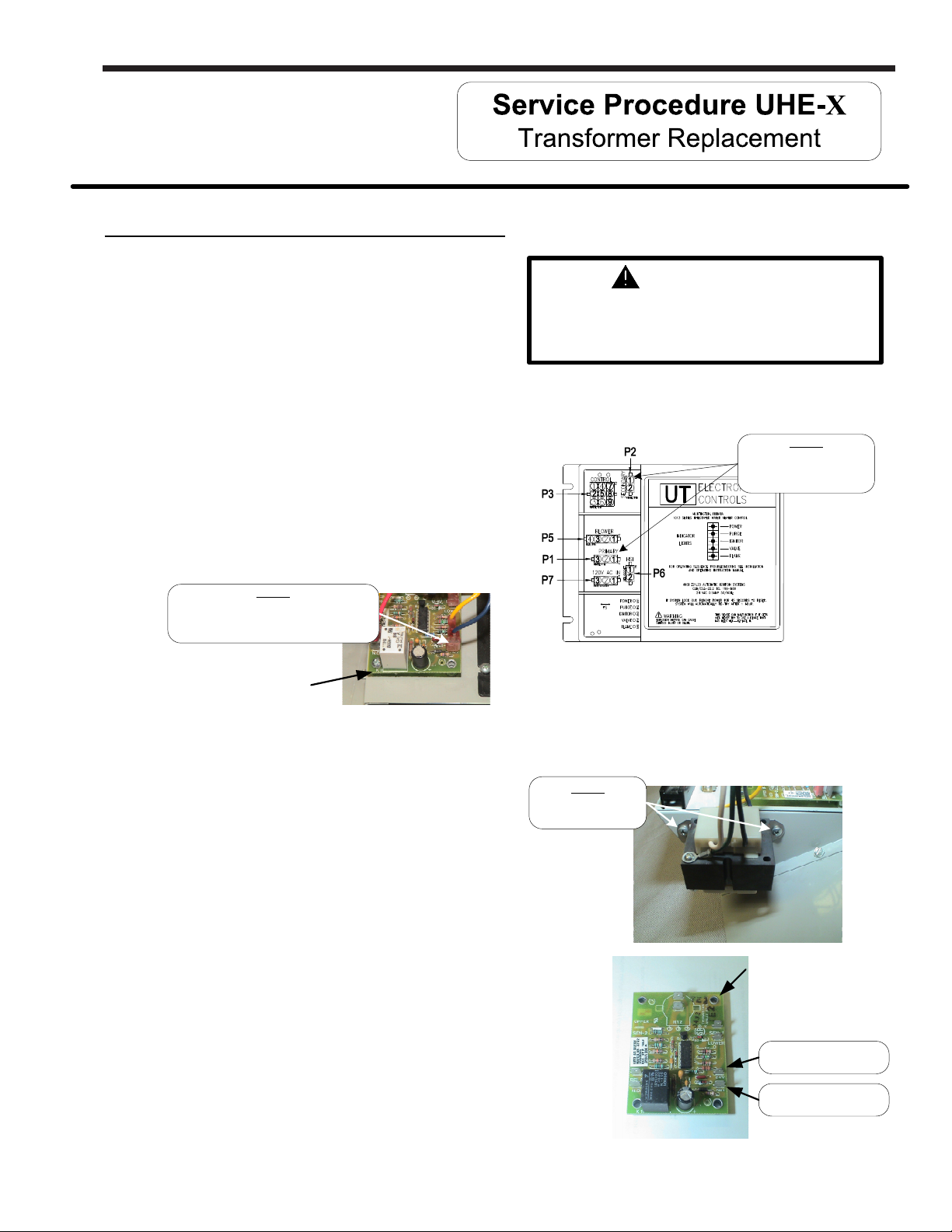
Step 4. For Hot Surface Ignition models, refer to ignition module illustration below, Disconnect wire harness
P1 labeled “PRIMARY” and P2 labeled “SECONDARY” from ignition module.
Step 3
Disconnect harness
Step 5. Disconnect secondary leads (blue &
yellow wire) from thermostat board.
“P1” & “P2”
from ignition module
Note the blue wire is connected to
24 volt “HOT” terminal. (see photo below)
Disconnect blue & yellow wire from
thermostat board. Note blue wire is
connected to 24 volt “HOT” terminal.
Step 5
Ignition module
Thermostat
board
Step 6. Remove the 2 screws ( short Phillips screw driver) holding the transformer in place and
remove transformer from control panel. (see photo below)
Step 7. Install new transformer and secure in
place with screws from step 6.
Step 6
Remove transformer
mounting screws
Step 8. Reconnect wire harness P1 & P2,
connections are non-interchangeable
to insure proper reconnection.
Step 9. Reconnect blue & yellow wire leading from the
P2 connection on ignition module to
thermostat board. Note the blue wire must connect to
the 24 volt “HOT” terminal. (see photo at right)
Step 10. Restore 120 volt power supply to water heater and
confirm proper operation following the lighting
instructions on the lighting instruction label or the
lighting instruction located in the installation and
operating instruction manual.
Step 11. Replace surround cover on top of water heater.
Thermostat
board
24 volt common,
yellow wire connection
24 volt Hot,
blue wire connection
35
Page 36
Page 36
LAARS Heating Systems
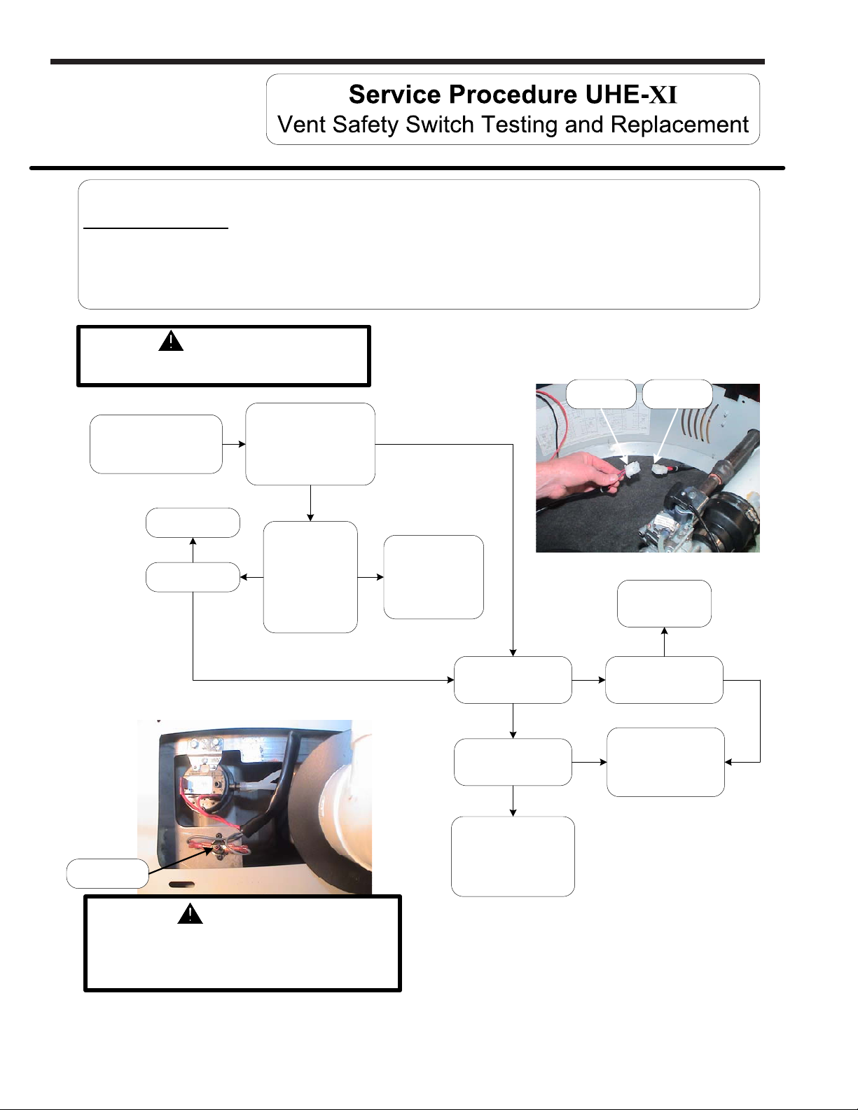
Sequence of operation:
With the thermostat calling for heat, prior to energizing blower, the ignition module checks the vent safety switch for normal
switch position of normally closed. If the vent safety switch contacts are open, (not in normal position), the ignition module waits
indefinitely for contact to close, The vent safety switch must be manually reset to close the switch contacts.
WARNING
120 volt potential exposure. Use caution
making voltage checks to avoid personal injury.
Heater side
harness
Locate harness
connection.
(see photo at right)
Is there continuity
Through GREY
Lead wires of heater side
harness?
(see photo at right)
Control side
harness
Y
Reset button
Call technical
support.
N
Does heater
function?
Y
Depress reset
button on high
limit switch. Is
Y
there continuity
across high limit
switch?
(see photo below)
N
N
Replace vent
safety switch
(see page 37)
Reset heater, observe
heating cycle. Does
switch open?
Y
Does switch open prior
to 350°F?
Y
Replace vent safety
switch
(see page 37)
N
Is temp over 350°F?
DO NOT OPERATE
N
System over heating,
immediately contact
System OK
N
Y
HEATER
technical support.
WARNING
Make sure exhaust collector compartment is not
overheating (350°F) before resetting vent safety
switch. If there is evidence the collector compartment
is overheating, CALL TECHNICAL SUPPORT.
36
Page 37
U.H.E Service Manual
Vent Safety Switch Replacement Procedure
Step 1. Position main power switch to “OFF”.
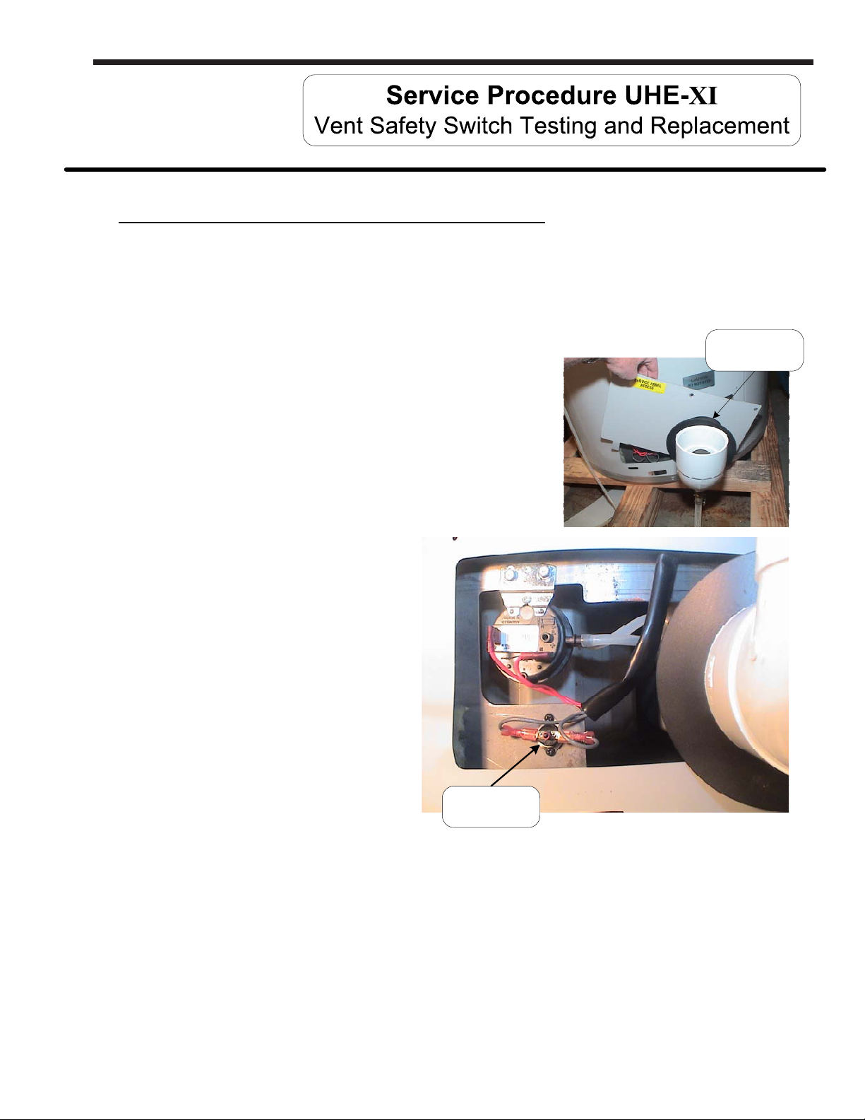
Step 2. Loosen adhesive backed rubber escutcheon from service panel access cover
and slide escutcheon back along exhaust pipe to allow for removal of cover
(see photos at right).
Step 3. Remove screws from service panel access cover
(¼" nut driver) and remove cover from heater
(see photos at right)
Page 37
Rubber
escutcheon
Step 4. Disconnect wire leads from vent
safety switch (see photo at right).
Step 5. Remove the 2 switch mounting
screws (Phillips screw driver)
and nuts (5/16 wrench) and
remove switch from heater.
Step 6. Install new switch using screws
from step 5.
Step 7. Reconnect wire leads.
Note: wire leads are
interchangeable with either
switch terminal.
Vent safety
switch
Step 8. Restore 120 volt power supply to water heater and confirm proper operation following the lighting
instructions on the lighting instruction label or the lighting instruction located in the installation and
operating instruction manual.
Step 9. Reinstall service panel access cover and
rubber escutcheon.
37
Page 38
Page 38
LAARS Heating Systems
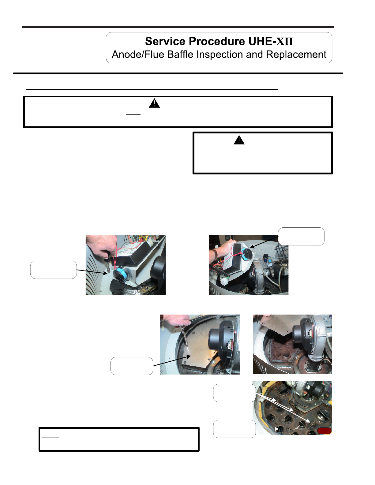
Disassembly Procedure for Access to Anodes & Flue Baffles
WARNING
Heater components may be HOT when performing the following steps in this procedure.
Take necessary precaution to prevent personal injury.
Step 1. Position main power switch to “OFF”.
Step 2. Disconnect (Unplug) water heater
from 120 Volt power source.
Step 3. Un-latch & remove surround cover from top of heater.
Step 4. Disconnect wire harnesses to allow for removal of control panel.
Note: Where ever possible, rather than disconnecting at the control panel, follow wire
harness away from control panel and disconnect at control component location.
Step 5. Remove the three control panel mounting screws (¼” nut driver) and remove control
panel from the water heater (see photos below).
Control Panel
Mounting Screw
Step 6. Completely remove insulation (two pieces) from top of heater to expose collector cover
120 volt potential exposure. Isolate the
appliance and reconfirm power is
disconnected using a multi-meter.
WARNING
Remove Control
Panel
Step 7. Remove all collector cover
screws (5/16" socket) and
remove collector cover
(see photos at right).
Collector
cover
Step 8. Photo 44 shows heater with collector cover removed allowing
access to anode rods and flue baffles.
a) for anode service, see page 39.
b) for flue baffle service, see page 40.
c) for powered anode service, see page 41.
Note: UHE100T399 models have only 1 anode
rod under the 2ndpass collector cover.
Anode
locations
Flue
baffles
38
Page 39
U.H.E Service Manual
Anode inspection and replacement
WARNING
Heater components and stored water may be HOT when performing the following steps in
this procedure. Take necessary precaution to prevent personal injury.
Step 1. Turn off water supply and drain water heater.
Step 2. Disassemble water heater per “Disassembly Procedure for Access to Andoes & Flue Baffles”.
Step 3. Locate and remove anode rods from heater (1-1/16 hex socket).
Step 4. Visually inspect anode rod. Anode rod should show signs of depletion, this is normal. If
the depletion is ½ of the original diameter (approximately ¾" diameter), replacement is
recommended. If any of the steel core of the anode is exposed, replacement is
recommended.
Page 39
Step 5. Upon completion of inspection or subsequent replacement, apply thread sealing tape or other
thread compound to threads of anode and reinstall into heater. Restore water supply
and check for and repair any leaks found.
Step 6. Reinstall collector cover per “Collector Cover Installation Procedure”.
Step 7. Reinstall collector insulation and control panel, reconnect control panel wire harnesses.
Step 8. Restore 120 volts to water heater and verify proper heater operation following the
instructions on the lighting instruction label or the lighting instruction located in the
installation and operating instruction manual.
Step 9. Replace surround cover on top of water heater.
39
Page 40
Page 40
LAARS Heating Systems
Flue baffle inspection and replacement
WARNING
Heater components may be HOT when performing the following steps in this procedure.
Take necessary precaution to prevent personal injury.
Step 1. Disassemble heater per “Disassembly Procedure for Access to Anodes & Flue Baffles”.
Step 2. Remove flue baffles from heater (pliers) (8 two inch baffles & 2 four inch baffles).
Step 3. Visually inspect flue baffles. Flue baffles should show signs of oxidation, this is normal.
If the oxidation has deteriorated any portion of the flue baffle, replacement is
recommended. If any restrictors are missing, replacement is recommended.
Step 4. Upon completion of inspection or subsequent replacement, reinstall flue baffles into
heater.
Step 5. Reinstall collector cover per “Collector Cover Installation Procedure” see page 42.
Step 6. Reinstall collector insulation and control panel, reconnect control panel wire harnesses.
Step 7. Restore 120 volts to water heater and verify proper heater operation following the
instructions on the lighting instruction label or the lighting instruction located in the
installation and operating instruction manual.
Step 8. Replace surround cover on top of water heater.
40
Page 41
U.H.E Service Manual
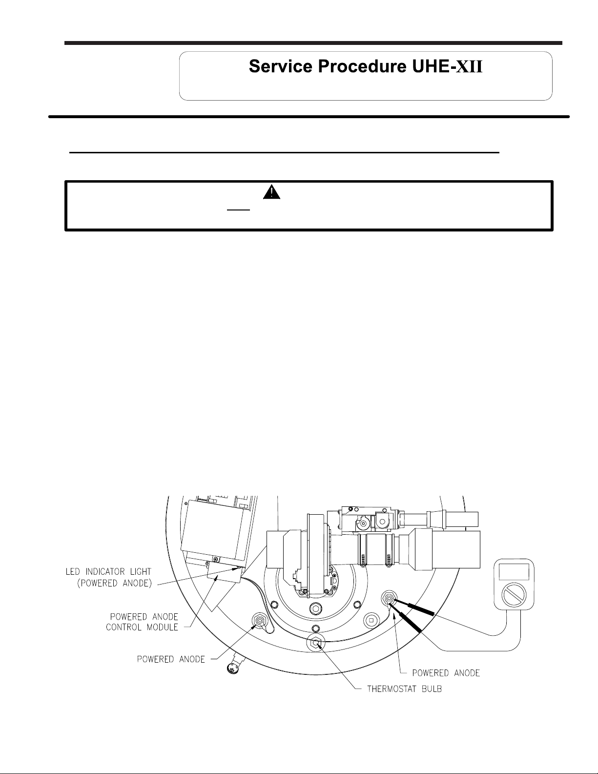
Powered Anode Replacement for UHE100T399 only
Powered Anode Replacement UHE100T399 models only
WARNING
Heater components may be HOT when performing the following steps in this procedure.
Take necessary precaution to prevent personal injury.
The powered anode control module is located on the right vertical side of the control panel inside the surround panel.
The control has a LED indicator light to show the status of operation. When the tank is filled with water and the power
supply is on to the water heater, the light should have a steady green glow to indicate that protection current is flowing
and operating normally. If the indicator light is not glowing, the power supply to the water heater or powered anode
system is disconnected.
Page 41
Step 1. Check the power supply or wire connections to the powered anode control.
Step 2. Indicator light diagnostic codes:
a) If the control is flashing red, then there is a malfunction with the powered anode system.
Make sure there are no bare spots in the wire insulation to the powered
anode rods.
Step 3. Check all electrical connections. The powered anode rods are insulated from the
water heater tank in the bushing.
a) With an ohmeter, check continuity between the powered anode terminal and the
bushing. There should not be continuity. If there is continuity, replace the powered
anode assembly.
Volt meter set
to OHM setting
41
Page 42
Page 42
LAARS Heating Systems
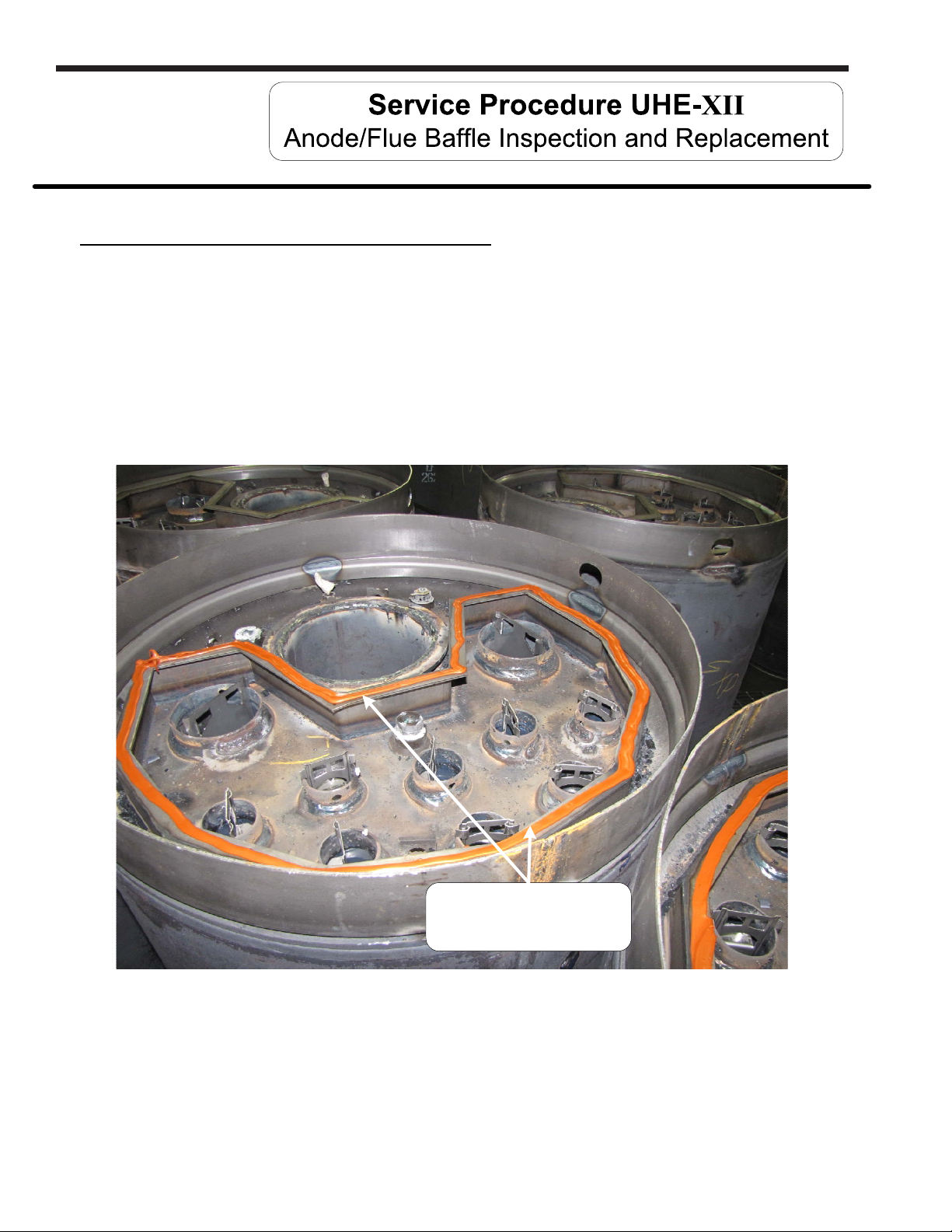
Collector Cover Installation Procedure
Step 1. Remove old silicone from top surface of collector flange and collector cover.
Step 2. Apply ¼" bead of Ultra Copper Silicone around entire collector flange surface. Allow
caulk to “cure” for 10 minutes.
Step 3. Carefully reinstall collector cover, tighten screws evenly.
Step 4. Allow a minimum of 6 hours before putting heater back in service.
Apply ¼" bead of Ultra Copper
Silicone around entire collector
flange surface
42
Page 43
U.H.E Service Manual
Product Handling - Carefully uncrate the heater. Move in place with a hand truck (Do not use the
venting pipes for handles).
Electrical Requirements - Make sure there is 120 volts line voltage. Line voltage must be properly
polarized. Adequate ground supplied to the heater.
Venting Requirements - All venting must stay within the required lengths and diameter (see table
below). Proper support of the venting pipe is a MUST (every 5ft vertical and 3ft horizontal).
Termination must be located to prevent re-circulation of flue gases. Medium to long sweep 90°
elbows or straight exhaust terminal coupling recommended.
Gas Requirements - Gas piping sized adequately, ¾" or larger to heater or 1" or larger for
UHE100T399 models. Install a properly sized regulator (if unknown, assure an adequate volume of
gas is available). 7" W.C. is required when the unit is running. Gas pressure must stay below 14"
W.C. static pressure. Pressure drops between static pressure and operating flow should be less
than 3" W.C.
Page 43
Condensate Requirements - Condensate line needs to slope to a drain at a minimum of ¼" per
foot. Make sure the condensate line does not have the potential to freeze. If using more than one
heater and using a common condensate line, make sure the condensate line is properly sized.
Service/Mechanical Room - Provide adequate space for servicing heater. Leave room to get to the
top and bottom pressure switches as well as enough overhead room to remove the anode rods for
servicing (18" min.).
Vent tables
Balanced Direct Vent Systems
PVC, CPVC
Total length of intake piping and exhaust piping
added together must not exceed “Maximum
Combined Length” Shown below
Maximum Combined Length (feet)
Model Number 3"
UHE60T125, UHE100T150 120'
UHE60T150, UHE100T199
UHE60T199 80' 130'
UHE100T250
100'
80'
4"
170'
150'
130'
Total length of exhaust piping must not exceed
Model Number 3"
UHE60T125, UHE100T150 120'
UHE60T150, UHE100T199
Power Vented Systems
PVC, CPVC
“Maximum Vent Length”
Shown below
Maximum Vent Length (feet)
4"
170'
100'
UHE60T199
UHE100T250 80' 130'
80'
150'
130'
UHE100T300
UHE100T399 50' 100'
Unbalanced Direct Vent Systems
Air intake CAN NOT exceed exhaust
by more than 30 feet
Note: each 3" & 4" 90° Elbow is equivalent to 5 feet of
straight pipe.
Note: each 3" & 4" 45° Elbow is equivalent to 2.5 feet of
straight pipe.
60'
110'
UHE100T300
UHE100T399 50' 100'
60'
110'
43
Page 44
Page 44
Date
LAARS Heating Systems
R
Service Provider
Phone Number
Venting (PVC, CPVC):
Vent size 3" or 4"
Intake 90's (qty)
Exhaust 90's (qty)
Gas Line:
Size & material
Distance from meter
to water heater
Electrical:
Line Voltage
Intake 45's (qty)
Exhaust 45's (qty)
Gas Pressure:
Static
Running Inlet
Manifold
Low Voltage
Model Number
Serial Number
Length of straight pipe
(intake)
Length of straight pipe
(exhaust)
Venturi:
Setting from Bottom in Turns
Polarity
Igniter Resistance:
LED Flashing Y or N Which One(s)
Error Codes on Control Display (Direct Spark Ignition System Only): __________________________________
Condensate Line:
Size & Material
Length
Is trap provided Y or N
Combustion:
CO2 CO
Installation Site Name & Address:
Flame Sense Micro -Amps:
Installation Site Contact Name & Phone
Spark Gap: ___________
Exhaust Collector Pressure:
Positive Inches W.C.
Number
44
Page 45
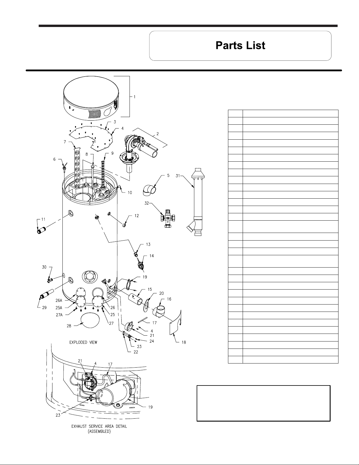
U.H.E Service Manual
Page 45
1 Combustion Surround Assy.
2 Burner Assy (specify model)
3 2ndPass Top Collector Cover
4 Screw 10-16 x 3/4
5 Vent Termination Elbow
6 Thermostat Sensor Probe
7 Baffle 4" Flue (specify model)
8a Anode Rod Assy
8b Powered Anode (for UHE100T399)
9 Baffle 2" Flue
10 Wire Harness Service Panel
11 Plastisert Nipple 1-½" NPT
12 Plug
13 Nipple
14 T&P Relief Valve
Exhaust Pipe (PVC) w/Hose Barb
15
(except UHE100T399)
16 Condensate Trap Elbow (specify model)
17 Silicone Hose
18 Outer Door Service Panel (specify model)
Vent Pipe Support Bracket (except
19
UHE100T399)
20 NSF Escutcheon
21 Exhaust Pressure Switch
22 Nuts
23 Collector Temperature Limit Switch
24 Screw 6-32x 3/8
25 Cleanout Access Cover
26 Cleanout Gasket
27 Screw 5/16-18 x ¾ HH Grade 5
28 Cleanout Cover
29 Cold Water Inlet (Hydrojet) Assy.
30 No Handle Brass Drain Valve
31 Concentric Vent System (optional)
32 ASSE Approved Mixing Valve (optional)
Customer must specify complete model
number and serial number when
ordering service parts.
45
Page 46
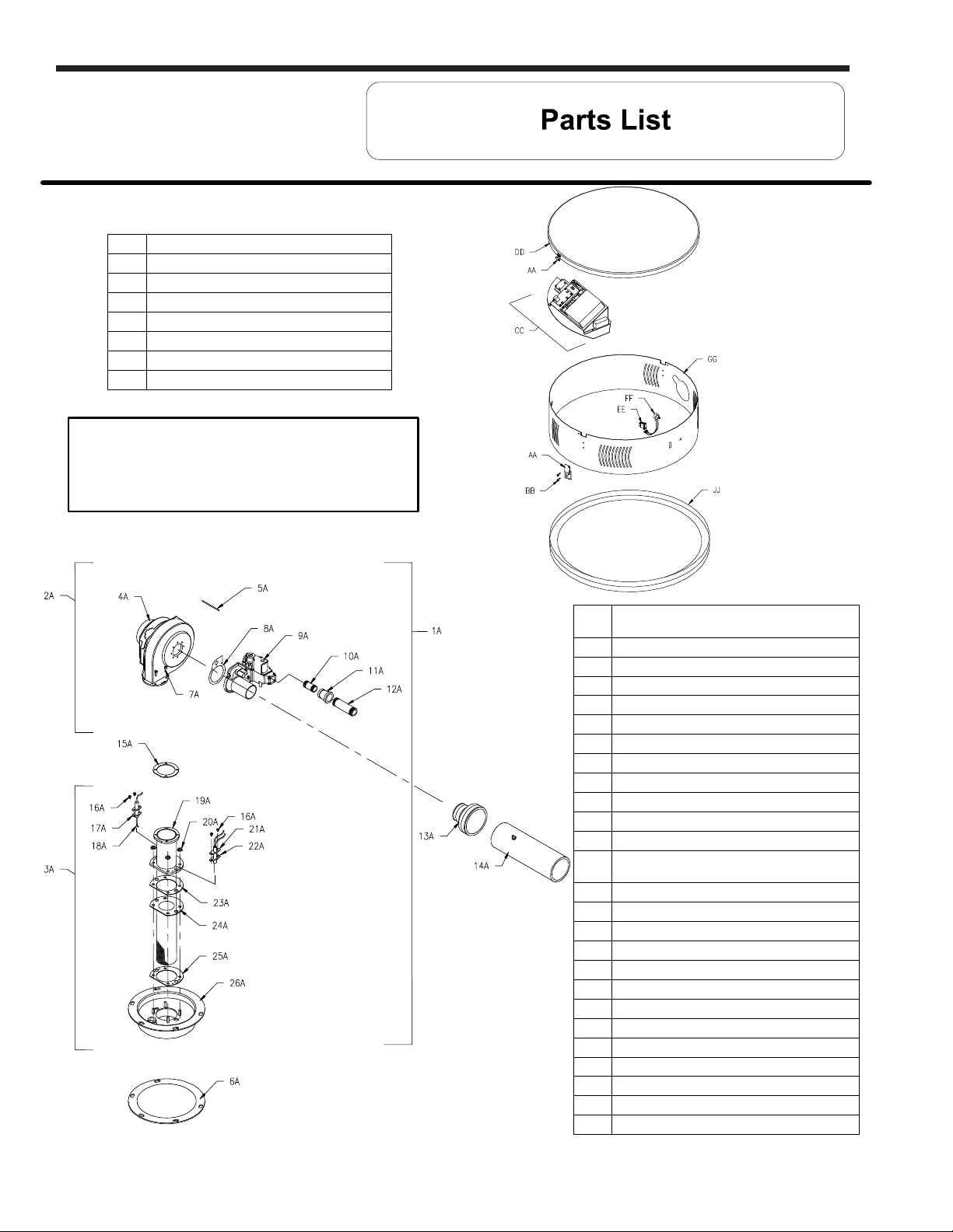
Page 46
AA Latch Assy
BB Screw 8-32 x ½ RHCR
CC Ignition Control Assy
DD Jacket Head
EE Main Power Switch
FF Potentiometer
GG Combustion Surround
JJ Surround Base
Customer must specify complete model
number and serial number when
ordering service parts.
LAARS Heating Systems
1A Combustion Surround Assy. (specify model)
2A Blower Gas Valve Assy (specify model)
3A Burner Assy (specify model)
4A Blower EBM (specify model)
5A Silicone Hose
6A Burner Mounting Insert Gasket
7A Screw 10-32 x3/4
8A Gasket & Screw
9A Gas Valve (specify model)
10A Nipple (specify model)
11A Reducer (specify model)
12A Nipple (specify model)
13A 2" dia. Flex Reducer (or PVC reducer for 399)
14A Inlet (PVC)
15A Gasket Blower Transition (specify model)
16A Screw 8-32 x ¼ RHCR
17A Gasket Flame Sensor
18A Flame Sensor
19A Transition Tube
20A Nut Hex Washer
21A Gasket Hot Surface Igniter
22A Hot Surface Igniter
23A Burner Mounting Gasket
24A Burner Tube
25A Burner Mounting Gasket
26A Burner Mounting Insert
46
Page 47
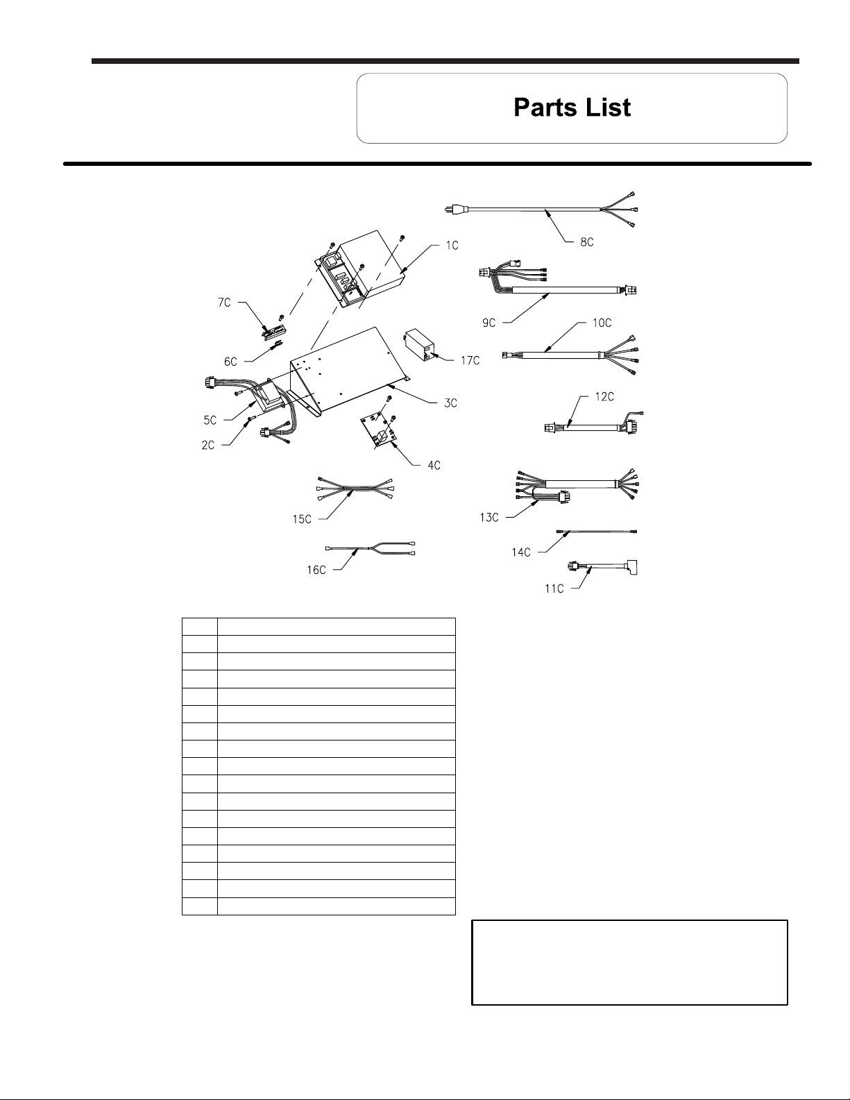
U.H.E Service Manual
Page 47
Electronic Control Module
1C
Screw 8-32 x 1/2
2C
Control Mounting Panel
3C
Thermostat PC Board
4C
Transformer 120VAC x 24VAC x 40VA
5C
Terminal
6C
Terminal Strip
7C
Power Cord
8C
Control Wire Harness
9C
Thermostat Wire Harness
10C
Rectifier Harness (specify model)
11C
Blower Wire Harness (specify model)
12C
Power Switch Wire Harness
13C
Flame Sensor Wire Harness
14C
Powered Anode Control Harness (399 only)
15C
Powered Anode Harness (399 only)
16C
Powered Anode Control (399 only)
17C
Customer must specify complete model
number and serial number when
ordering service parts.
47
Page 48
Page 48
LAARS Heating Systems
AC Alternating Current
BTU/H British Thermal Units
CO Carbon Monoxide
CO2 Carbon Dioxide
DC Direct Current
DSI Direct Spark Ignition
ECO Energy Cut Off
GFI Ground fault interrupt
GPM Gallons per Minute
HSI Hot Surface Igniter
Hz Hertz
LED Light Emitting Diode
NOx Oxides of Nitrogen
NPT National Pipe Thread
PSI Pounds per Square Inch
RPM Revolutions per Minute
VA Volt Amps
VAC Volts Alternating Current
W.C. Inches of Water Column
°C Degrees Centigrade
°F Degrees Fahrenheit
µA Micro Amp
NOTES
800.900.9276 • Fax 800.559.1583 (Customer Service, Service Advisors)
20 Industrial Way, Rochester, NH 03867 • 603.335.6300 • Fax 603.335.3355 (Applications Engineering)
1869 Sismet Road, Mississauga, Ontario, Canada L4W 1W8 • 905.238.0100 • Fax 905.366.0130
www.Laars.com Litho in U.S.A. © Laars Heating Systems 1302 Document 11019A
 Loading...