

Page 1
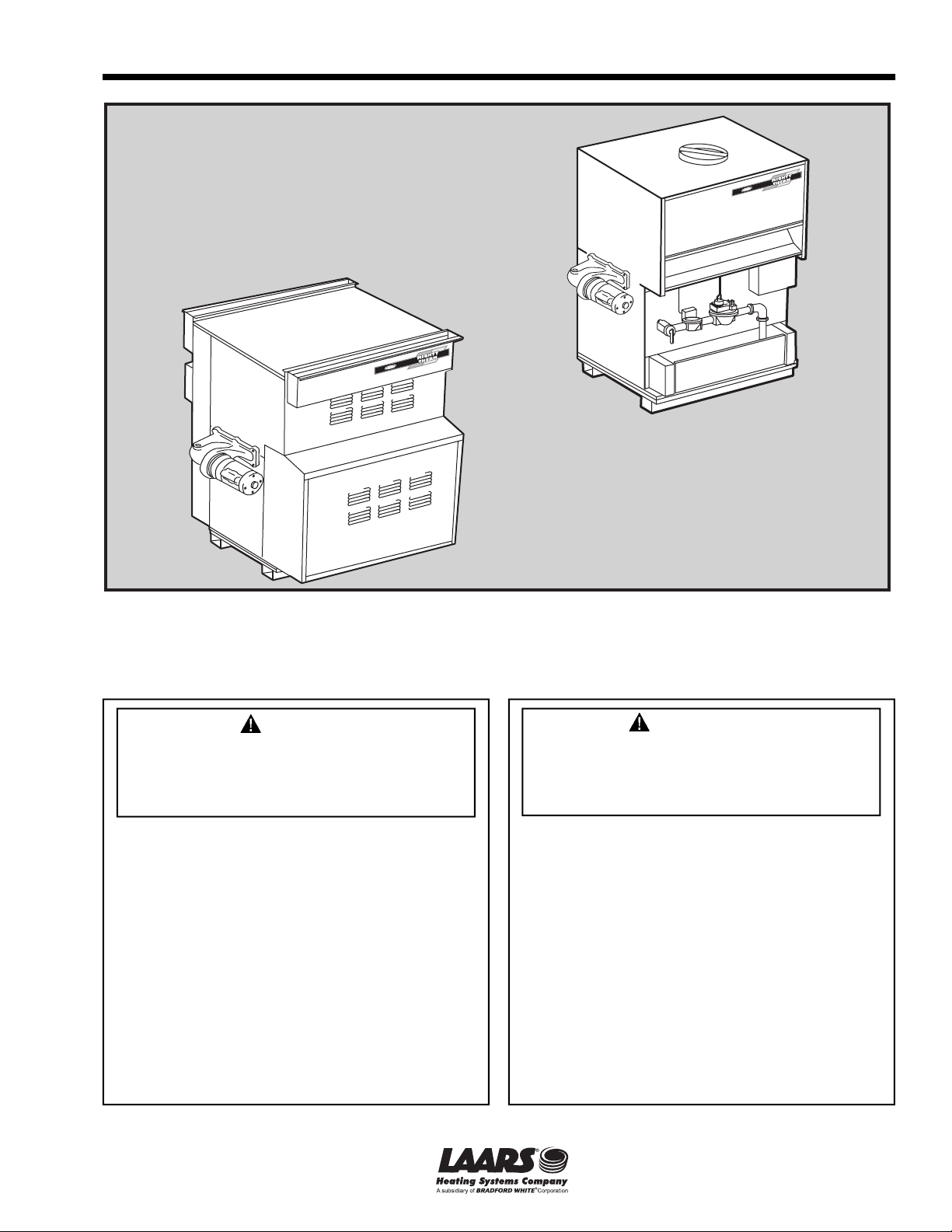
Installation and Operation Instructions Document 3006T
Installation and Operation
Instructions for
Mighty Therm
Pool Heating Boiler
Model AP
Sizes 500 - 1825
These instructions are to be stored in the
pocket provided on the heater.
FOR YOUR SAFETY: This product must be installed and serviced by a professional service technician,
qualifi ed in hot water heater installation and maintenance. Improper installation and/or operation could
create carbon monoxide gas in fl ue gases which could cause serious injury, property damage, or death.
Improper installation and/or operation will void the warranty.
WARNING
If the information in this manual is not
followed exactly, a fi re or explosion may
result causing property damage, personal
injury or loss of life.
Do not store or use gasoline or other
fl ammable vapors and liquids in the vicinity of
this or any other appliance.
WHAT TO DO IF YOU SMELL GAS
• Do not try to light any appliance.
• Do not touch any electrical switch; do not
use any phone in your building.
• Immediately call your gas supplier from a
nearby phone. Follow the gas supplier's
instructions.
• If you cannot reach your gas supplier, call
the fi re department.
Installation and service must be performed
by a qualifi ed installer, service agency, or gas
supplier.
Assurez-vous de bien suivres les instructions
données dans cette notice pour réduire au
minimum le risque d’incendie ou d’explosion ou
pour éviter tout dommage matériel, toute blessure
ou la mort.
Ne pas entreposer ni utiliser d’essence ni d’autres
vapeurs ou liquides infl ammables dans le voisinage
de cet appareil ou de tout autre appareil.
QUE FAIRE SI VOUS SENTEZ UNE ODEUR DE GAZ:
• Ne pas tenter d’allumer d’appareils.
• Ne touchez à aucun interrupteur. Ne pas vous
servir des téléphones dansle bâtiment où vous
vous trouvez.
• Appelez immédiatement votre fournisseur de
gaz depuis un voisin. Suivez les instructions du
fournisseur.
• Si vous ne pouvez rejoindre le fournisseur de
gaz, appelez le sservice des incendies.
L’installation et l’entretien doivent être assurés par un
installateur ou un service d’entretien qualifi é ou par le
fournisseur de gaz.
AVERTISSEMENT
H0067300T
Page 2

Page 2
LAARS Heating Systems
Table of Contents
Section 1
General Information
1.1 Introduction ....................................................3
1.2 Heater Identifi cation .......................................3
1.3 Primary/Secondary Pump and Piping ............3
1.4 Certifi cations ..................................................3
1.5 Engineering Assistance ................................. 3
Section 2
Installation
2.1 Heater Placement ..........................................4
2.2 Installation of Indoor Heaters ......................... 4
2.2.1 Combustion Air Supply ..................................4
2.2.2 Venting ...........................................................5
2.2.3 Common Venting System
Test Procedure ..............................................6
2.2.3 Instructions Relatives au Test des
Systèmes à Évent Commun ..........................6
2.3 Installation of Outdoor Heaters ......................7
2.4 Gas Supply and Piping ..................................7
2.5 Electrical Wiring .............................................8
2.6 General Piping Instructions ...........................9
2.7 Heater By-Pass Piping ..................................9
2.8 Temperature Sensor Placement
and Installation ..............................................9
2.9 Automatic Chlorinators ................................10
Section 3
Operation
3.1 Controls - General .......................................10
3.2 Initial Start-Up .............................................. 11
3.3 Safety Shutoff Component Checkout .......... 12
3.4 Inlet Temperature and
Temperature Rise Adjustment .....................13
3.5 Heater Shut Down ....................................... 13
3.6 Spring and Fall Operation
Stand-by Service .........................................13
3.7 Winter Operation Complete Shutdown ........ 14
3.8 Time Clock Operation ..................................14
3.9 Therapeutic Pools (Spas) ............................ 14
Section 4
Maintenance ..................................................... 15
Section 5
Troubleshooting
.............................................16
Section 6
Parts Description and Order Numbers ..18
Page 3
Mighty Therm Commercial Pool Heating Boiler
Page 3
Section 1
General Information
1.1 Introduction
This manual provides information for the installation
and operation of Laars Model AP pool heating boilers.
It is strongly recommended that all application and
installation procedures be reviewed completely before
proceeding with the installation. Consult the Laars
factory, or local factory representative, with any problems
or questions regarding this equipment. Experience has
shown that most problems are caused by improper
installation, not system design.
Some accessory items are shipped in separate packages.
Verify receipt of all packages listed on the packing slip.
Inspect everything for possible damage upon delivery,
and inform the carrier of any shortages or impairments.
Any such claims should be fi led with the carrier. The
carrier, not the shipper, is responsible for shortages and
damage to the shipment whether visible or concealed.
WARNING
The model AP commercial pool heater must
be used on potable water only. For heating
pools containing salt water, a specially
equipped heater must be used; consult your
distributor or factory representative. The
pool heater must be installed in accordance
with the procedures outlined in this manual.
The warranty does not apply to heaters not installed or
operated in accordance with these procedures. Consult
local building and safety codes before proceeding with
work. The installation must conform to the requirements
of the authority having jurisdiction or, in the absence of
such requirements, to the latest edition of the National
Fuel Gas Code; ANSI Z223.1, National Electrical Code
ANSI/NFPA 70. In Canada, the installation must conform
with the latest edition of CSA B149 requirements.
When required by the authority having jurisdiction,
the installation must conform to American Society of
Mechanical Engineers safety codes for controls and
safety devices for automatically fi red heaters No. CSD-1,
and in Canada CSA 3.3. Any modifi cation of the heater,
its gas controls, gas orifi ces, wiring or drafter diverter
may void the Laars warranty. If fi eld conditions require
such modifi cations, consult the factory.
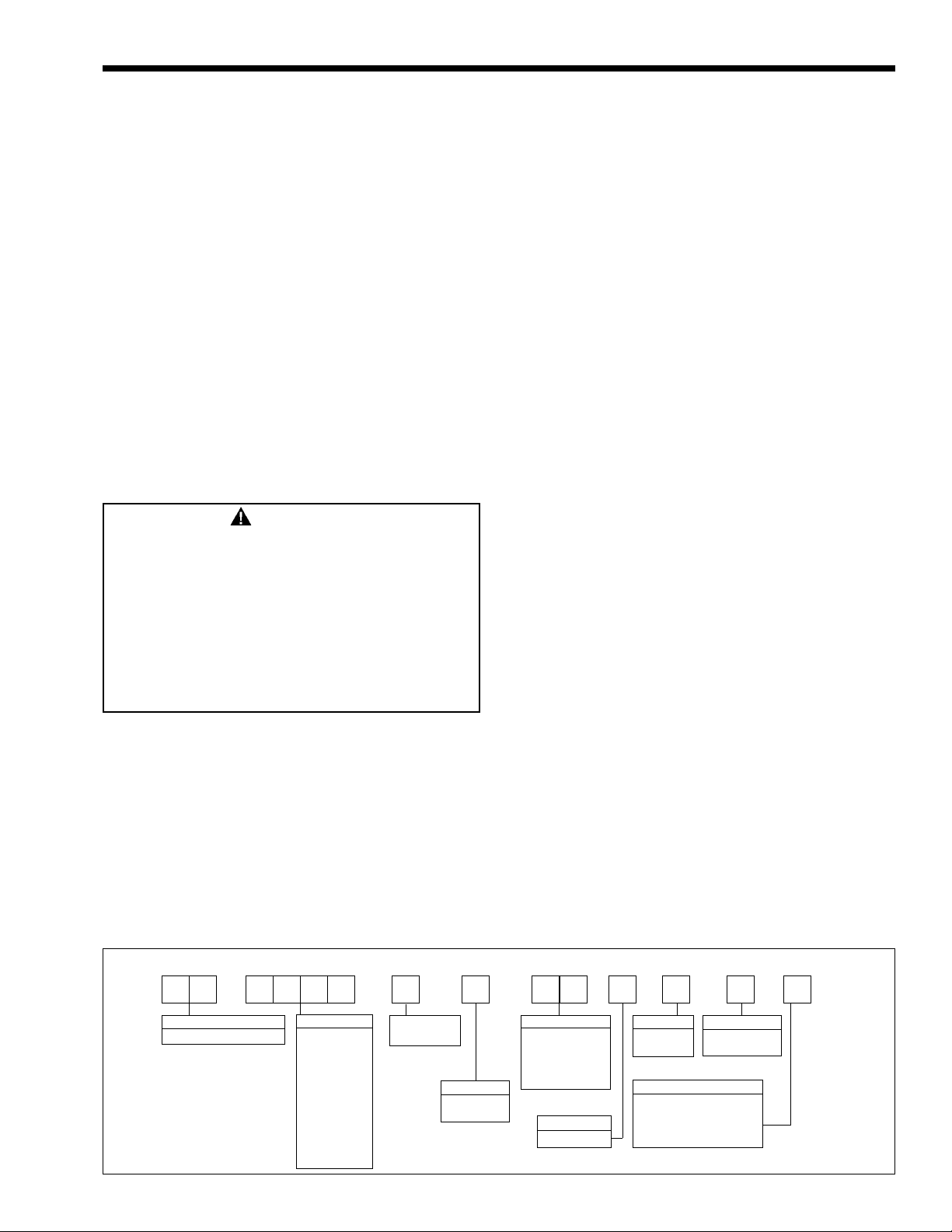
1.2 Heater Identifi cation
Consult rating plate on the heater. Shown below is a
breakdown of the model nomenclature. Laars commercial
pool heating boilers are available in two confi gurations:
an indoor version and an outdoor version. Outdoor
models are not available in Canada.
1.3 Primary/Secondary Pump and Piping
All models are supplied with integrally mounted pumps.
The 1825 models use a 3/4 HP pump and all other models
are supplied with 1/2 HP pumps. These pumps are sized
for the pressure drop through the heat exchanger and
through the bypass piping as shown in Figure 10.
Any deviations from the arrangement shown may
increase the head on the pump, reduce fl ow and hinder
performance (see Section 2.7). For spas see Section 3.9.
This piping arrangement and the integral pump allow hot
water to be recirculated to the heater inlet, thus raising
the inlet temperature and greatly reducing condensation.
1.4 Certifi cations
All models are design-certifi ed by CSA for natural or
propane gas and conform to ASME Code requirement for
160 PSI water pressure.
1.5 Engineering Assistance
Consult the factory or distributor regarding any questions
or problems which arise in the specifi cation, installation
or operation of Laars equipment. An experienced
engineering staff is ready to assist in assuring the proper
performance and application of Laars products.
1 2 3 4 5 6 7 8 9 10 11 12 13 14
MODEL
AP-POOL
Figure 1. Heater Identifi cation (Model Nomenclature)
SIZE
BTU/HR X 1000
0500
0600
0715
0850
0999
1010
1200
1430
1670
1825
I-INDOOR
E-OUTDOOR
FUEL
N-NATURAL
P-PROPANE
IGNITION
04-SPARK 110V
09-SPARK 24V
11-SPARK 24V
16-STND. PILOT
FIRING MODE
ON/OFF
C
VERSION
1 - 8 TUBE
B-10 TUBE
HEAT EXCHANGER
C-GLASS LINED/COPPER
N-GLASS LINES/CU-NI
K-BRONZE/COPPER
S-BRONZE/CU-NI
REVISION
P-PUMP (U.S.)
Q-PUMP (CAN)
Page 4
Page 4
LAARS Heating Systems
Section 2
Installation
2.1 Heater Placement
The pool heater must be placed to provide specifi c
clearances on all sides for maintenance and inspections.
There must also be minimum distances maintained from
combustible surfaces. These clearances also apply to
noncombustible materials because the pool heater requires
air circulation for proper operation.
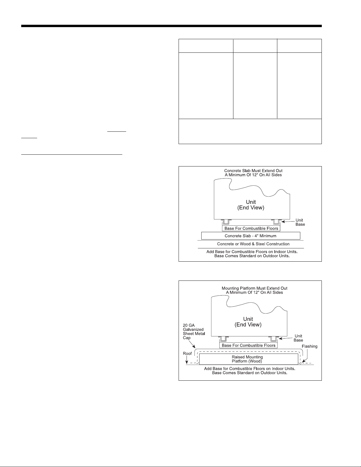
The pool heater should be mounted on a level surface. An
integral base for an installation on combustible fl ooring is
provided as standard equipment on outdoor models. For
indoor models, special base rails part number 10539000
must be used for combustible fl ooring.
Do not install a pool heater on carpeting.
Under the national Fuel Gas Code, ANSI Z223.1, it
is permissible to place the heater on fl oors other than
noncombustible when the installation complies with the
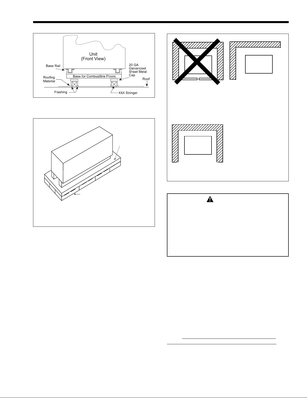
American Insurance Code. Figures 2, 3, 4 and 5 show
common installation on combustible fl ooring.
2.2 Installation of Indoor Heaters
Locate the pool heater to provide adequate clearance
for inspection and service on all sides. See Table 1. For
alcove installation, see Figure 6.
Install indoor heaters on a waterproof fl oor with an
adequate fl oor drain and a 6" (152mm) minimum curb on
all four sides to protect the building if heater repairs are
required. The manufacturer will not be held liable for
any water damage in connection with this heater.
2.2.1 Combustion Air Supply
The heater location must provide suffi cient air supply
for proper combustion and ventilation of the surrounding
area as outlined in the latest edition of ANSI standard
Z223.1, and any local codes that may be applicable. Inadequate combustion air supply may result in incomplete
combustion, sooting of the heat exchanger, and unsafe
operation of the heater.
Clearance Indoor Outdoor
from in. mm in. mm
Top 30 762 unobstructed
Water Conn. side 12* 305 24 610
Pump side 6* 152 24 610
Front Alcove* unobstructed
Rear 8 203 24 610
Vent pipe** 6 152 - - -
Hot water pipes per code per code
* Water connection and pump side clearances of 24"
(610mm) and front clearances of 48" (1219mm) will allow
easier service access.
** Using type B vent (refer to Manufacturer's Instructions).
Table 1 - Minimum Heater Clearances
from Adjacent Surfaces
Figure 2 - Typical Heater Installation on Concrete Slab
a. Conventional Ventilation
In the United States, the most common of these requirements specify that boiler rooms should be provided with
two permanent air supply openings communicating directly through the wall to outside air one within 12 inches
(305mm) of the ceiling, and the other within 12 inches
(305mm) of the fl oor. Each opening should have a minimum free area of one square inch (6.5 sq. cm) per 4,000
BTU/hr input of the total input rating of all appliances in
the enclosed area. See Table 2 for recommended air supply
for each model. An improperly ventilated equipment room
can get excessively hot and cause accelerated deterioration
of controls and electrical components.
Pool heaters installed in vaults (“pits”) must have
combustion air ducted to bottom of the vault, even if the top
is unobstructed. Ducting should be sized for a minimum of
one square inch (6.5 sq. cm) per 2,000 BTU/hr input of the
Figure 3 - Typical Heater Installation on Roof
Using Raised Platform (Wood)
total input rating of all appliances in the vault. Contact the
Service Department for more information.
In Canada, Table 2 does not apply. Consult local building
codes or, in the absence of such requirements, follow
CSA B149 standard.
Page 5
Mighty Therm Commercial Pool Heating Boiler
Page 5
Water
Heater
Figure 4 - Typical Heater Installation on Roof
Using 4x4 Stringer
Base must extend out
min. 12" (305mm) on
all sides of
heater frame.
Concrete blocks or tile min. 7" (178mm)
high with 3" (76mm) min. air openings.
Blocks must provide solid base and be braced so they
cannot slip out of place. Air openings in blocks must be
arranged to provide unobstructed opening through entire
width or length of base.
Figure 5 - Installation on Concrete Blocks or Tile
20 ga. min.
galvanized sheet
metal
under entire
heater.
b. Forced-Air Ventilation
In the United States: any equipment which exhausts air
from the boiler room can deplete the combustion air
supply or reverse the natural draft action of the venting
system. This could cause fl ue products to accumulate
in the boiler room. Additional air must be supplied to
compensate for such exhaust. The information in Table
2 is not applicable in installations where exhaust fans or
blowers of any type are used. Such installations must be
designed by qualifi ed engineers.
In Canada: follow Canadian standard, CSA B149 or local
codes.
If a blower or fan is used to supply air to the boiler room,
the installer should make sure it does not create drafts
which could cause nuisance shutdowns of the pilot. If a
blower is necessary to provide adequate combustion air
to the heater, a suitable switch or interlock must be wired
into the heater control circuit to prevent the heater from
fi ring unless the blower is operating.
The heater must be completely isolated and protected
from any source of corrosive chemical fumes such as
trichlorethylene, perchloroethylene, chlorine, etc.
CLOSET INSTALLATION
(UNACCEPTABLE)
A closet is any 4 sided enclosure
which is less than 16* times the total
volume of all the gas fired appliances
within the enclosure.
Water
Heater
* When the ceiling height exceeds 8 feet, you are only allowed to consider 8
feet when calculating the total volume of the enclosure.
Figure 6 - Alcove Installation
ROOM INSTALLATION
(ACCEPTABLE)
A room is any enclosure which is at
least 16* times greater than the total
volume of all the gas fired appliances
within the enclosure.
ALCOVE INSTALLATION
(ACCEPTABLE)
An alcove suitable for the installation
of a water heater is a restricted section
of a room not separated from the
room by a door or partition and which
meets the minimum clearances for
the specific model water heater listed
below.
WARNING
Chemicals stored in the equipment room may
cause corrosion. Sodium hypochlorite feeders,
vented tablet containers, pellet salt and other
chemicals may off-gas into the air in the room
and be drawn into the combustion and dilution
air, corroding the pool heater's metallic parts.
Corrosion damage is not covered under the
limited warranty.
2.2.2 Venting
Laars heaters have built-in draft diverters for natural draft
operation and must not be connected to any portion of a
mechanical draft system under positive pressure. The fl ue
outlet must be connected to a clear, unobstructed vent of
adequate capacity ending above the highest point of the
building with an approved vent cap. The venting system
should be installed according to the latest edition of
ANSI Z223.1 and/or, in Canada, CSA B149 and any local
codes having jurisdiction.
Do not weld or fasten the vent pipe to the heater
drafthood. The weight of the stack must not rest on the
heater. The drafthood and heater top must be easily
removable for normal heater service and inspection.
IMPORTANT NOTE: Do not use sheet metal screws at
the snap lock joints of Type B gas vents.
Avoid using long horizontal runs of the vent pipe, and too
many 90° elbows, reductions or restrictions. Horizontal
runs should have at least a 1/4" (6mm) rise per foot in the
Page 6

Page 6
LAARS Heating Systems
direction of fl ow. A vent connector should be supported
for the design and weight of the material used to maintain
clearances and prevent physical damage and separation
of joints.
Avoid terminating heater vents near air conditioning
or air supply fans. The fans can pick up exhausted fl ue
products from the heater and return them inside the
building creating a possible health hazard. A minimum
of 4 feet (1.2m), in Canada 6 feet (1.8m), horizontal
distance must be maintained from electrical meters, gas
meters, and relief equipment.
Always use double-wall or insulated vent pipe (Type B
or equivalent). In cold weather, uninsulated outside vents
can chill the rising fl ue products blocking the natural
draft action of the venting systems. This can create a
health hazard by spilling fl ue products in the boiler room.
When the installation of a draft fan is necessary
in connecting a venting system to a Laars heater,
the installation should be engineered by competent
personnel following good engineering practices. The
draft fan supplier should be consulted for correct size.
The installation should be in accordance with the latest
edition of ANSI Z223.1 and/or, in Canada, CSA B149
and any local codes having jurisdiction. When a draft
fan is installed, a suitable draft switch must be wired into
the heater control circuit at terminal designated "Field
Interlock" to prevent fi ring of the heater unless a positive
draft has been established.
2.2.3 Common Venting System
Test Procedure
At the time of the removal of an existing heater, the
following steps shall be followed with each appliance
remaining connected to the common venting system.
During the testing of each unit, the other appliances
remaining connected to the common venting system
should not be operated.
1. Seal any unused openings in the common venting
system.
2. Visually inspect the venting system for proper size
and horizontal pitch. Determine that there is no
blockage or restriction, leakage, corrosion, or other
defi ciencies which could cause an unsafe condition.
3. Insofar as it is practical, close all building doors and
windows. Also close all doors between the space
in which the appliances remaining connected to the
common venting system are located and the other
spaces of the building. Turn on any clothes dryer
and any appliance not connected to the common
venting system. Turn on any exhaust fans, in clud ing
range hoods and bath room ex hausts, so they will
operate at maximum speed. Do not operate a
summer exhaust fan. Close all fi replace dampers.
4. Place in operation the appliance being in spect ed.
Follow the lighting instructions for the unit.
Adjust the thermostat so the appliance will operate
continuously.
5. Test for spillage at the draft hood relief opening
after 5 minutes of main burner operation. Use
the fl ame of a match or candle, or smoke from a
cigarette, cigar, or pipe.
6. After it has been determined that each appliance
remaining connected to the common venting system
properly vents when tested as outlined above, return
doors, windows, exhaust fans, fi replace dampers and
any other gas-burning appliance to their previous
condition of use.
7. Any improper operation of the common venting
system should be corrected so the installation
conforms with the National Fuel Gas Code, ANSI
Z223.1 and/or CSA B149, Installation Codes. When
resizing any portion of the common venting system,
the common venting system should be resized to
approach the minimum size as determined using the
appropriate tables in Appendix G in the National
Fuel Gas Code, ANSI Z223.1 and/or CSA B149
Installation Codes.
2.2.3 Instructions Relatives au Test des Systèmes à
Évent Commun
Au moment du restrait dʼune chaudière existante, les
mesures suivantes doivent être prises pour chaque
appareil toujours reccordé au système dʼévacuation ne
fonctionnet pas:
1. Sceller toutes les ouvertures non utilisées du
systèmes dʼévacuation.
2. Inspecter de façon visuelle le système dʼévacuation
pour déterminer la grosseur et lʼinclinaison
horizontale qui conviennent et sʼassurer que le
système est exempt dʼobstruction, dʼétranglement,
de fuite, de corrosion et autres défaillances qui
pourraient présenter des risques.
3. Dans la mesure du possible, fermer toutes les portes
et les fenêtres du bâtiment et toutes les portes entre
lʼespace où les appareils toujours raccordés au
système dʼévacuation sont installés et les autres
espaces du bâtiment. Mettre en marche les sécheuses, tous les appareils non raccordés au système
dʼévacuation common et tous les ventilateurs
dʼextraction comme les hottes de cuisinière et les
ventilateurs des salles de bain. Sʼassurer que ces
ventilateurs fonctionnent à la vitesse maximale. Ne
pas faire fonctionner les ventilateurs dʼété. Fermer
les registres des cheminées.
4. Mettre lʼappareil inspecté en marche. Suivre les
instructions dʼallumage. Régler le thermostat de
façon que lʼappareil fonctionne de façon continue.
5. Faire fonctionner le brûleur principal pendant 5 min
ensuite, déterminer si le coupe-tirage déborde à louverture
de décharge. Utiliser la fl amme dʼune chandelle ou la
fumée dʼune cigarette, dʼune cigare ou dʼune pipe.
6. Une fois quʼil a été déterminé, selon la méthode
indiquée ci-dessus, que chaque appareil raccordé
au systéme dʼévacuation est mis à lʼair libre de
façon adéquate. Remettre les portes et les fenêtres,
les ventilateurs, les registres de cheminées et les
appareils au gaz à leur position originale.
Page 7
Mighty Therm Commercial Pool Heating Boiler
Page 7
7. Tout mauvais fonctionnement du systéme
dʼévacuation commun devrait être corrigé de façon
que lʼinstallation soit conforme au National Fuel Gas
Code, ANSI.Z223.1 et (ou) aux Codes dʼInstallation
CSA B149. Si la grosseur dʼune section du système
dʼévacuation doit être modifi ée, le système devrait
être modifi é pour respecter les valeurs minimales des
tableaux pertinents de lʼappendice G du National
Fuel Gas Code, ANSI Z2231.1 et (ou) des Codes
dʼInstallation CSA B149.
2.3 Installation of Outdoor Heaters
1. Locate the heater to provide the clearances as listed
in Table 1, “Minimum Heater Clearances.”
2. Do not place the heater in an enclosure or wall
recess. Avoid locations where wind defl ection off
structures might cause downdraft. When such wind
conditions are possible, place the heater at least 3
feet (0.9m) from the structures.
3. If the heater must be installed in a four sided
enclosure with an open top, such as when
equipment is surrounded by block walls, provision
for combustion air at the bottom of the enclosure
must be provided even if the enclosure is large.
Openings with a minimum of 1 square inch (6.5
sq. cm) per 4,000 BTU/hr input of all appliances
contained in the enclosure must be located in the
walls within 12” of the fl oor to provide enough
combustion air for the pool heater.
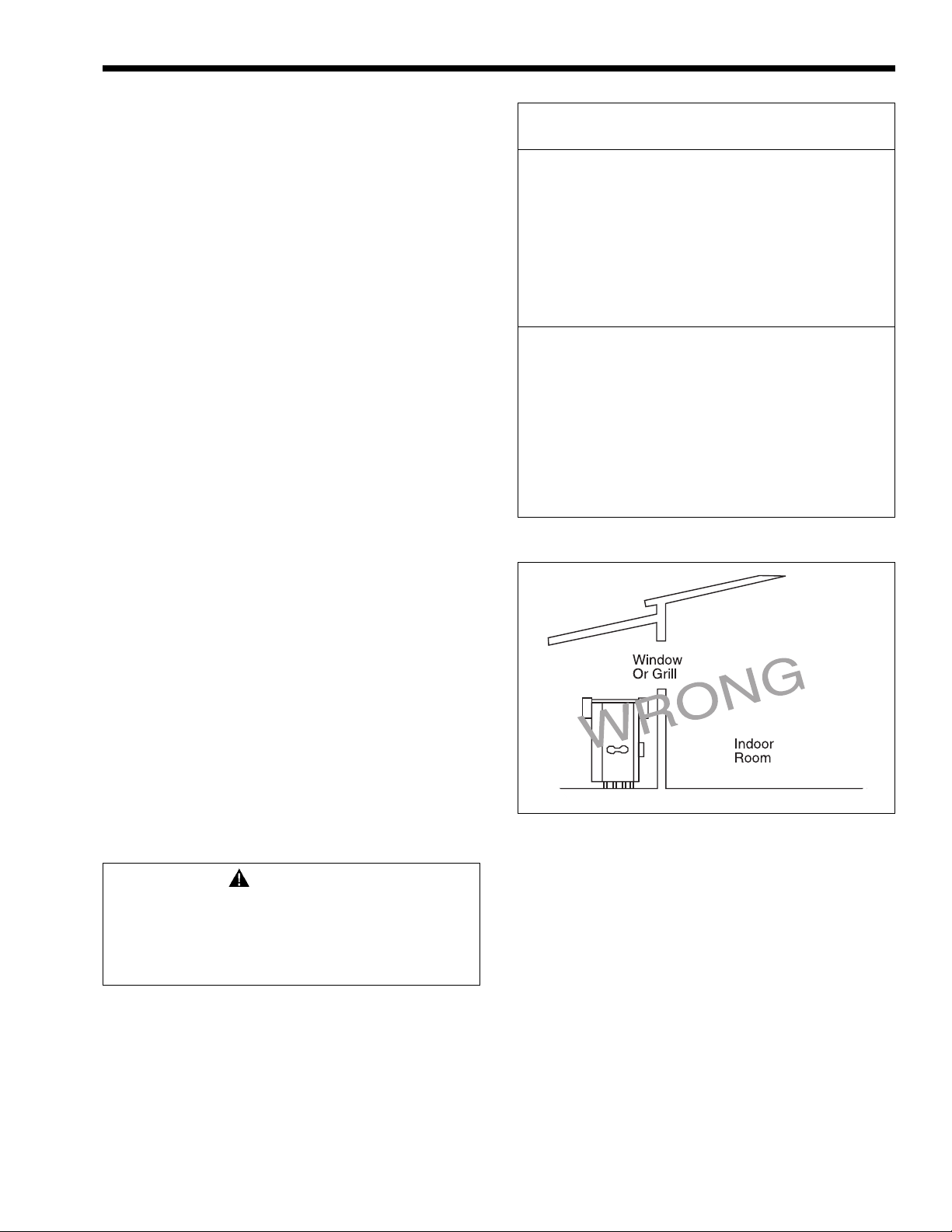
4. Never install the heater under any kind of roof
overhang. Do not place the heater below or adjacent
to any doors, windows, louvers, grills, etc., which
connect in any way with an inhabited area of a
building. This includes other structures such as
garages or utility rooms (see Figure 7).
5. Although these models are CSA design certifi ed
for outdoor installations, such installations are not
recommended in areas where the danger of freezing
exists unless proper precautions are taken for freeze
protection.
Outdoor installations are not recommended in areas
where the danger of snow blockage exists.
WARNING
Liquefi ed petroleum gas is heavier than air.
Therefore, the pool heater should not be
installed in pits or other locations where gas
could accumulate.
The heater should be located a safe distance from
Propane gas storage and fi lling equipment. Consult local
codes and fi re protection authorities for advice on specifi c
installation restrictions.
2.4 Gas Supply and Piping
Review the following instructions before proceeding with
the installation.
1. Verify that the heater is fi tted for the proper type of gas
by checking the rating plate. Laars heaters are normally
Heater Each Opening*
Size square inches square cm
500 125 806.5
600 150 967.8
715 179 1154.9
850 213 1374.3
1010 253 1632.4
1200 300 1935.6
1430 358 2309.8
1670 418 2696.9
1825 457 2948.6
Net Free Area.
*
Check with louver manufacturers for net free area of louvers.
Correct for screen resistance to the net free area if a screen is
installed. Check all local codes applicable to combustion air.
Area indicated is for one of two openings: one at fl oor level and
one at the ceiling, so the total net free area could be double the
fi gures indicated. For special conditions refer to the latest edition
of ANSI Z223.1.
Consult factory if openings do not communicate directly through
the walls with the outdoors.
Table 2 - Minimum Recommended Air Supply to Heater
Figure 7 - Incorrect Outdoor Installation
equipped to operate below a 2000 foot (609.6m)
altitude. Heaters equipped to operate at higher altitudes
have appropriate stickers or tags attached, also printed
information on rating plate.
2. Use the fi gures in Table 3 to provide adequate gas
piping from the gas meter to the heater.
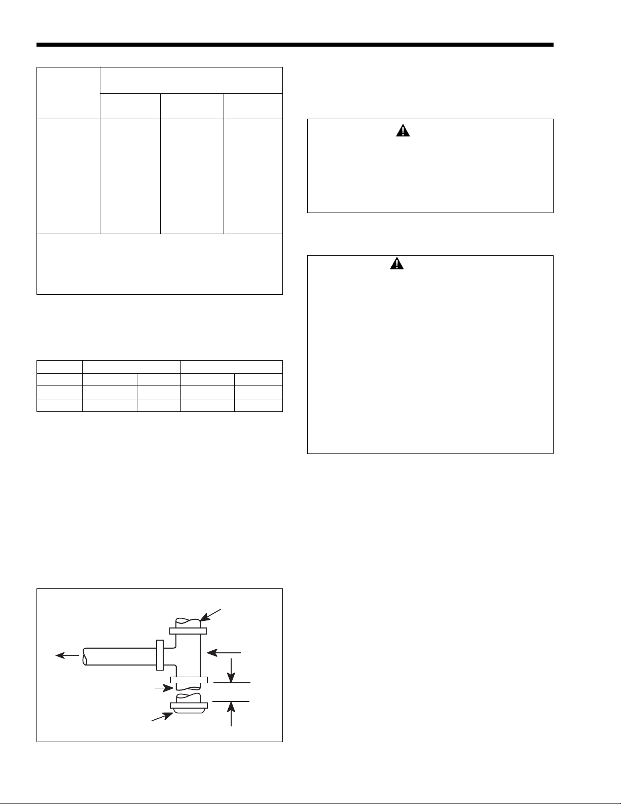
3. A sediment trap (drip leg) must be provided ahead
of the gas controls (see Figure 8). A manual gas
shutoff valve must also be provided for service
convenience and safety. Check the local codes.
4. The heater and its individual shutoff valve must be
disconnected from the gas supply piping system
during any pressure testing of that system at test
pressures in excess of 1/2 psig (3.5kPa). The heater
must be isolated from the gas supply piping system
by closing its individual manual gas shutoff valve
during any pressure testing of the piping system at
test pressures equal to or less than 1/2 psig (3.5kPa).
Page 8
Page 8
LAARS Heating Systems
Distance from Gas Meter
Heater or Last Stage Regulator
Size
0-30.5m 30.5-61m 61-91.4m
500 1½" 2" 2"
600 1½" 2" 2½"
715 2" 2" 2½"
850 2" 2½" 2½"
1010 2" 2½" 3"
1200 2½" 3" 3"
1430 2½" 3" 3"
1670 2½" 3" 3
1825 2½" 3" 3½"
NOTE: These fi gures are for Natural Gas (.65 Sp. Gr.), and are
based on 1/2" water column pressure drop. Check supply pressure
with a manometer, and local code requirements for variations. For
Propane Gas, reduce pipe diameter one size. An average number
of tees and elbows have been taken into account.
Table 3 - Gas Piping Sizes
0-100' 100-200' 200-300'
5. Provide gas supply pressure to the heater as
follows:
Natural Gas Propane Gas
In. W.C. kPa In. W.C. kPa
Max. 10 2.5 13 3.4
Min. 6.5 1.6 11 2.7
NOTE: the heater and all other gas appliances sharing
the heater gas supply line must be fi ring at maximum
capacity to properly measure the inlet supply pressure.
Low gas pressure could be an indication of an undersized
gas meter and /or obstructed gas supply line.
6. The correct burner manifold gas pressure is
stamped on the rating plate. The regulator is preset
at the factory and normally requires no further
adjustment.
The gas manifold and control assembly is
factory tested and conforms to the safe lighting and other
performance criteria specifi ed in the latest editions of
ANSI Z21.13.CSA4.9, Low Pressure Boiler Standard.
Gas Supply
To
Equipment
Inlet
Nipple
Cap
Figure 8 - Sediment Trap Installation
Inlet
Te e
Fitting
3" (76mm) Min.
Before operating the heater, the complete gas supply
system and all connections must be tested for leaks using
a soap solution. Do not use raw fl ame.
Caution
Since some leak test solutions (including soap
and water) may cause corrosion or stress
cracking, the piping must be rinsed with water
after testing, unless it has been determined
that the leak test solution is noncorrosive.
2.5 Electrical Wiring
WARNING
The heater must be electrically grounded in
accordance with the most recent edition of
the National Electrical Code, ANSI/NFPA 70.
In Canada, all electrical wiring to the heater
should be in accordance with the latest edition
of CSA C22.1 Canadian Electrical Code, Part
1. Do not rely on the gas or water piping to
ground the metal parts of the heater. Plastic
pipe or dielectric unions often isolate the
heater electrically. Service and maintenance
personnel who work on or around the heater
may be standing on wet fl oors and could be
electrocuted by an ungrounded heater.
Wiring diagrams are included in the information packet
provided with each unit.
1. All Model AP pool heating heaters need 115V
60Hz supply voltage unless specifi cally ordered
otherwise.
2. The 1825 models are supplied with 3/4 HP pump
motors. All other models are supplied with 1/2 HP
pump motors. Consult the National Electrical Code
or the Canadian Electrical Code regarding branch
circuit requirements for equipment with these
motors.
3. The heaters should be wired exactly as shown in the
wiring diagram.
IMPORTANT NOTE: The pool fi lter pump and heater
must be electrically interlocked so the heater cannot
come on unless the pump is running and there is full
fl ow in the fi lter piping where the heater is connected. If
the pool fi lter pump operation is intermittent the heater
must be shut off prior to pump shutdown. See paragraph
heading Auxiliary Time Clock Wiring on the next page.
If the backwash operation is manual the heater must be
shut off manually during backwashing.
Page 9
Mighty Therm Commercial Pool Heating Boiler
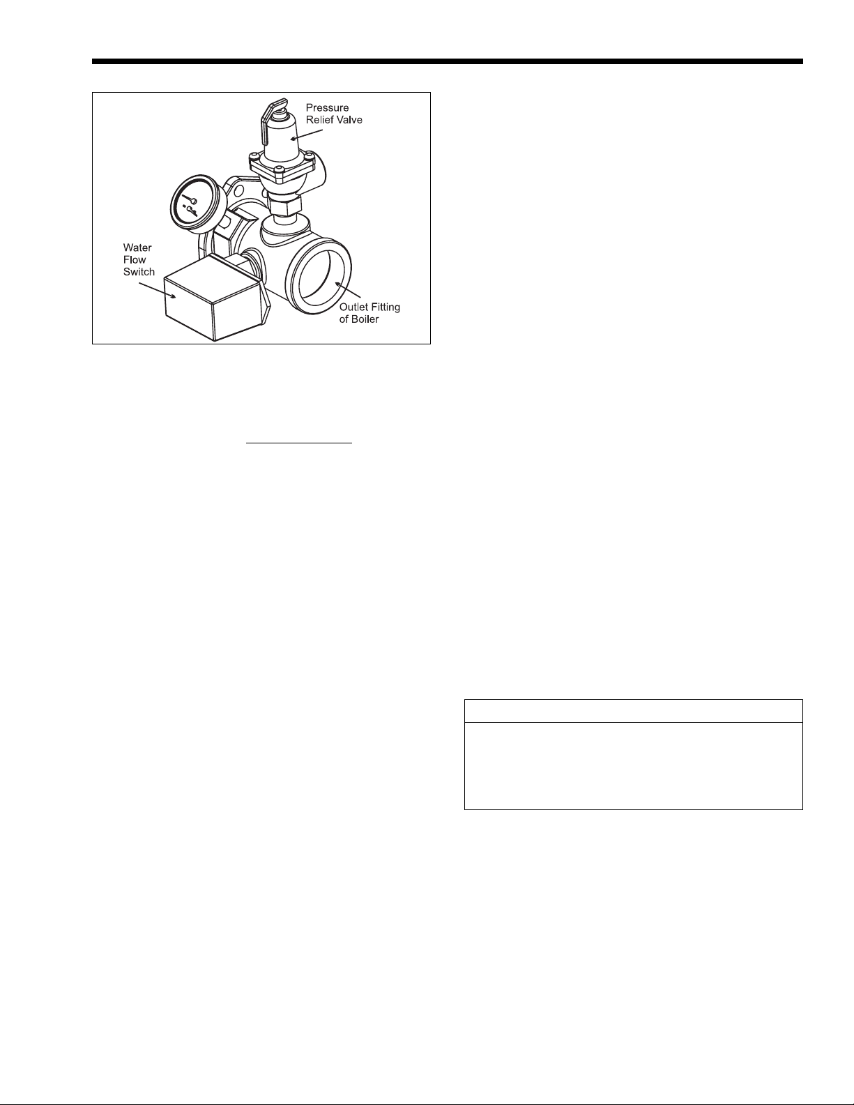
Figure 9 - Pressure Relief Valve Location
Auxiliary Time Clock Wiring:
If a time clock is used to control the fi lter pump
operation, a separate switch or relay must be used to
shut off the heater at least 15 minutes before the fi lter
pump is shut off. Wire the switch or relay (often called
the Fireman Switch) to the terminals shown in the wiring
diagram as “Field Interlock.”
4. All fi eld installed electrical safety devices and all
fi eld installed controllers (valve end switches, draft
switches, relays, timers) can be connected to the
heater control to the terminals shown in the wiring
diagram designated “Field Interlock.”
5. Field location of the temperature sensor is
described in Section 2.8.
Where the heater is installed with a draft fan refer to
the fan manufacturer's wiring diagram. The draft switch
should be wired across the fi eld interlock terminals in the
heater control panel.
Page 9
The pressure relief valve lever must be tripped at least
once a year to ensure that waterways are clean. When
manually operating lever, water will discharge through
the drain line. Precautions must be taken to avoid contact
with hot water and water damage.
2.7 Heater By-Pass Piping
All AP series heaters, 500-1825 models, must be installed
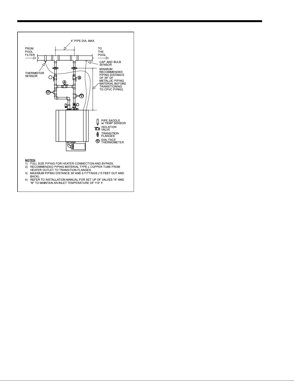
with bypass piping. Please use Figure 10 as your guide to
plumb the bypass. For spas see Section 3.9.
All models are supplied with integral pumps. These
pumps are sized for the pressure drop through the heat
exchanger, 30' of piping, and through the bypass piping
as shown in Figure 10.
If the distance from the pool heater to the pool loop
piping is greater than 15' please contact the Service
Department for assistance (see back page for phone and
fax numbers).
Any deviations from the arrangement shown may reduce
fl ow, hinder performance, and will void the warranty.
2½ inch NPT piping is shown, however, models 500I1430I and models 500E-1010E may be installed using 2
inch NPT piping.
All models must be installed in the primary/secondary
arrangement shown. The heater loop piping must tee into the
fi lter loop piping with the inlet and outlet connection spaced
a maximum of 4 pipe diameters apart (see Figure 10).
The integral pump will provide the right amount of fl ow
for the pool heater, and the return water to the pool will
be maintained below 104°F, provided the piping diagram
is followed correctly and the fi lter pump fl ow rate is at
least the “Minimum Filter Pump Flow Rate” in Table 4.
The outlet valve “B” and the bypass valve “A” must have
a provision for locking the handles in place (or removing
them) after the temperature rise and inlet temperature
adjustments have been made.
2.6 General Piping Instructions
In addition to the bypass valve “A” and outlet valve
“B” shown in Figure 10, an inlet valve “C” should be
provided so that the heater can be readily isolated for
service. Butterfl y and globe valves are recommended for
this application to allow for precise adjustment of water
fl ows. For spa applications see Section 3.9.
Since heater outlet temperatures can reach 150°F (66°C)
in some cases, copper or CPVC are recommended
materials for heater connection piping. PVC material may
be used for the inlet valve and the piping upstream of it.
When pipe, fi ttings, grids or any other element of the
fi lter system are made of plastic materials, they may be
damaged by the momentary "back siphoning" of hot
water from the heater when the fi lter pump stops running.
The pressure relief valve installed in the tapped opening
provided in the outlet header (see Figure 9), must be
piped, but not connected, to a drain or fl oor sink. The
drain pipe must be the same size as the valve outlet and
must pitch downward from the valve. Where no special
setting of the relief valve is ordered, the factory will
furnish a 75 psi setting.
Heater Model Minimum Filter Pump Flow Rate
500-850 90 GPM
1010-1200 110 GPM
1430 140 GPM
1670-1825 180 GPM
Table 4 - Minimum Flow to Supply Heater Loop
2.8 Temperature Sensor Placement
and Installation
Two temperature sensing devices are installed on the
heater that require sensing bulbs be fi eld installed
according to Figure 10.
1. Install the thermistor based sensor's immersion
well on the underside of the pool loop piping. The
well should be installed just upstream of the heater
inlet tee. DO NOT INSTALL the bulb in the
heater loop piping or down stream of the heater
outlet tee.
Page 10
Page 10
LAARS Heating Systems
after the pump shuts off will not siphon chlorine
solution into the heater.
4. When the operation of a chlorinator is such
that it must be installed in the pump suction, or
some other place where the chlorine solution
fl ows through the heater, corrosion of the heater
can occur. Excessive concentrations of chlorine
C
caused by improper adjustment or failure of the
chlorination equipment cause this corrosion. The
resulting damage to the heat exchanger is not
covered by heater warranty.
Section 3
Operation
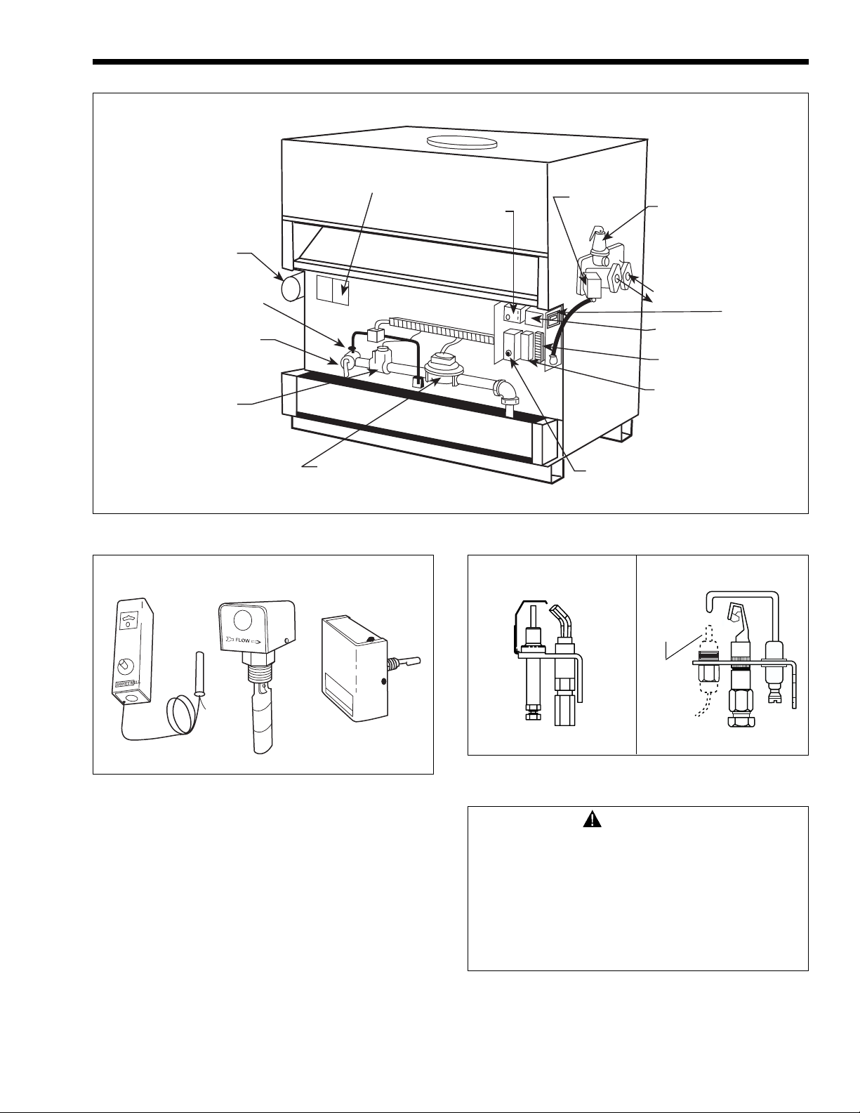
3.1 Controls - General
(See Figures 11 and 12)
1. Electronic Ignition Controls:
a. Intermittent Ignition:
Figure 10 - Heater Piping Arrangement
2. Thread the spring and retainer onto the sensor cable
and secure sensor into the immersion well.
3. Route cable to heater control panel in a location
where it will not be subject to damage. Secure with
nylon cable ties.
4. Install the capillary tube/bulb sensor immersion
well on the underside of the pool loop piping. The
well should be installed just downstream of the
heater outlet tee. DO NOT INSTALL the bulb in
the heater loop piping or upstream of the heater
outlet tee.
5. Route the capillary tube in a location where it will
not be subject to damage. Secure with wire ties.
2.9 Automatic Chlorinators
A concentration of chlorine in the heater can be very
destructive, therefor the following rules about the
installation and operation of such devices must be
followed:
1. The chlorinator should be installed so it introduces
the gas or solution downstream from the heater.
2. The chlorinator should be wired so it cannot operate
unless the fi lter pump is running.
3. The chlorinator should be provided with an antisiphon device so that the draining of the piping
Pilots are automatically lit when the operating
control calls for heat (Systems #4, #9, and
#11). The unit performs its own safety check
and opens the main valves only after the pilot
is proven to be lit. Whenever the pilot fl ame is
interrupted, the main gas valve closes within
0.8 seconds.
b. Electronically Supervised Standing Pilot
System (System #16):
When pilot fl ame fails, the ignition control
module responds in less than 0.8 seconds and
provides 100% safety shutdown.
2. Operating Controls:
An electronic temperature control is provided
on model AP heaters to control the pool water
temperature. The temperature sensor (thermistor) is
located in the pool loop piping (see Section 2.8).
3. Heater Power (On/Off/Auto) Switch:
This provides for constant or automatic pump
operation.
4. High Limit Controls:
a. The manual reset high limit switch is
provided as standard equipment on all heaters.
The temperature sensing bulb of the switch is
always located in the heater outlet. Burners
will automatically shut down whenever
overheating of water occurs.
b. The auto reset limit switch is provided as
standard equipment on all heaters. The
temperature sensing bulb of the switch is fi eld
installed and should be located in the pool
loop piping. (See Section 2.8 for installation
instructions.) Burners will automatically shut
down whenever overheating of water occurs.
Page 11
Mighty Therm Commercial Pool Heating Boiler
Page 11
Water
Circulating
Pump
Manual
Pilot
Val ve
Manual
Main
Gas Valve
Safety
Gas
Val ve
Figure 11 - Control Locations
Manual Reset
High Limit
Flow
Switch
Rating Plate
Operating/Safety
Gas Valve
Low Water
Cutoff
(Optional)
Ignition Control
Flow
Switch
Out
Hi-Limit
Spark Ignition Standing Pilot
Pressure
Relief
Val ve
In
Pump Time
Delay Relay
Terminal Strip
Operating
Controls
Power
(On/Off/Auto)
Switch
Figure 12 - Safety Components
5. Flow Switch:
Standard on all AP pool heating heaters. The switch
is mounted in a tee fi tting on the outlet header.
This is a paddle type switch which is defl ected
by the water fl ow in the fi tting. Any condition
which interrupts or decreases the fl ow through the
secondary loop will shut down the burners.
6. Low Water Cut Off (optional):
The low water cut off automatically shuts off heater
whenever water level in the heat exchanger drops
below probe level. It is located in the inlet header,
and is a manually reset device.
Thermo-
couple
Figure 13 - Pilot Burners
3.2 Initial Start-Up
WARNING
Do not use this appliance if any part has
been under water. Immediately call a qualifi ed
service technician to inspect the heater. The
possible damage to a fl ooded appliance can
be extensive and present numerous safety
hazards. Any appliance that has been under
water must be replaced.
Newly constructed pools may have low pH, and higher
levels of calcium hardness or construction debris. Do
not allow pool water to circulate through the pool heater
until the water has been fi ltered to remove all debris,
Page 12
Page 12
LAARS Heating Systems
and the chemical balance of the water has been adjusted
to a stable pH of 7.2 to 7.8. After the pool water is
fi ltered, and the pH is verifi ed at 7.2 to 7.8, verify that the
chlorine or bromine residual is no more than 2.0 to 4.0
ppm, the total alkalinity is 80 - 120 ppm and the calcium
hardness is between 200 - 400 ppm. Corrosion and/or
“liming” of the heat exchanger is possible when these
levels are not maintained and the heater is fi red.
1. Before placing the heater in operation, be certain
that the heater is fi lled with water and that all air is
purged from the system. Open all the valves in the
secondary piping.
2. With the fi lter pump running, run the heater pump in
manual “CONSTANT PUMP” for minimum of 10
minutes and listen for the fl ow switch to make as the
pump is started. Loosen the pipe plug on the top of the
pump scroll casting to bleed off any air. NOTE: If the
system will be operated in a manner that causes air to
be drawn into the heater and the secondary piping, an
automatic fl oat type air vent should be permanently
installed on top of the pump scroll.
3. To check the heater fi ring, proceed as follows:
a. Turn off the power switch.
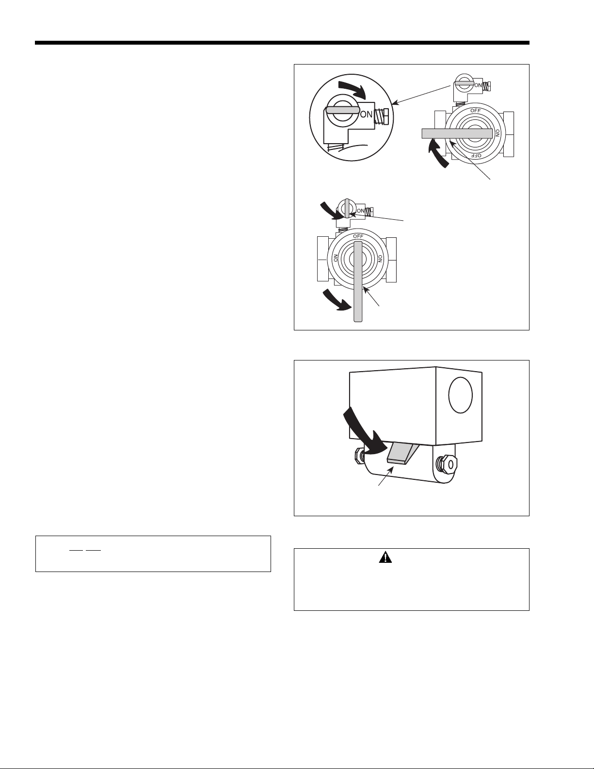
b. Turn off all manual gas valves and wait fi ve
minutes (Figure 14).
c. Set operating control to the lowest setting.
d. After placing the manual pilot gas valve in the
open position and resetting all safety devices
(high limit, low water cutoff, etc.), the pilot(s)
can be lit following the procedure on the
heater rating plate.
e. For standing pilot system, press on pilot
relay lever (see Figure 15), light pilot and
keep relay lever depressed for one minute
then release. Once the pilot is lit, turn power
switch to “AUTO PUMP.”
f. Wait 5 minutes and turn up operating
control until heater fi res (for intermittent
ignition system, the pilot will be ignited
automatically). The main burners should
ignite smoothly. Turn the operating control
back to the lowest setting.
Pilot Valve
ON POSITION
Main Gas Valve
Pilot Valve
OFF POSITION
Main Gas Valve
Figure 14 - Manual Gas Valves.
Pilot Relay Manual
Reset Switch
(Standing Pilot Systems)
Figure 15 - Pilot Safety Relay.
Note: Do not operate the heater until the
following safety checks have been performed.
3.3 Safety Shutoff Component Checkout
1. Once the pilot(s) is lit and has been established for
fi ve minutes, the fl ame failure response time should
be checked as follows:
Systems 4, 9, and 11 - (intermittent ignition). With this
system pilots are automatically lit when the operating
controls call for heat. If the pilot fl ame fails for any
reason, the main valve is shut off within one second and
the pilot spark ignition is initiated until the pilot fl ame
has been reestablished. This sequence should be checked
by turning off the manual pilot gas valve (see Figure 14),
and, at the same time, monitoring the audible sparking at
the pilot burner and signal interruption to the main valve.
Caution
Propane gas is heavier than air and sinks to
the ground. Exercise extreme care in lighting
the heater when so equipped.
System 16 - (electronically supervised standing pilot
system). Extinguish the pilot fl ame by placing the manual
pilot valve in the closed positions (see Figure 14), and at
the same time, begin recording the time it takes for the
output signal from the electronic ignition control to be
interrupted. The signal interruption can be detected either
with a test light or a voltmeter. The response time should
never exceed one second.
Page 13

Mighty Therm Commercial Pool Heating Boiler
Page 13
2. Manual Hi-Limit Checkout. The manual high limit
capillary bulb is installed at the heater outlet. (This
is not the auto reset high limit installed in the pool
return line). For spas see Section 3.9. The manual
reset high limit is factory preset to 150°F (66°C).
Confi rm this set point on the unit and adjust if
necessary. After running the heater in a fi ring mode
for 10 minutes, slowly close the outlet valve “B”
to raise the outlet temperature as indicated on the
outlet thermometer. The high limit should trip
within 2°F (1°C) or 3°F (2°C) of the 150°F (66°C)
setpoint and shut off the burners. If this does not
occur, adjust the set point on the unit to shut off the
burners when the outlet thermometer reads 150°F
(66°C). Open the outlet valve “B” and push the
reset button. The main burners should reignite.
3. Flow Switch: See attached vendor literature.
4. Low Water Cutoff (optional): See attached vendor
literature.
3.4 Inlet Temperature and Temperature
Rise Adjustment
For proper operation the bypass and outlet valves must be
adjusted to obtain the correct heater temperature rise and
inlet water temperature. Use the following method to set
the bypass assembly at start up:
1. With all bypass valves open, fi re the heater for at
least 10 minutes. The operating control should
be set at least 5° to 10° F (2.8° to 6°C) above the
pool tem per a ture to ensure continued operation
through out this set up procedure.
2. Observe the thermometer on the inlet header. To
prevent condensation and damage to the heater, the
inlet water temperature has to be 110°F (43°C).
If the inlet temperature is LESS THAN
110°F (43°C): With the bypass valve
“A” fully open, throttle (turn down) outlet
valve “B” slightly. Observe the inlet
thermometer for 5 minutes to see where the
inlet tem per a ture stabilizes. If it remains
under 110°F (43°C), throttle outlet valve “B”
a little more. Repeat as necessary. If the
inlet tem per a ture rises above 110°F (43°C),
open outlet valve “B” slightly until the inlet
temperature stabilizes as close to 110°F as
possible (plus or minus 2°F (1°C)).
If the inlet temperature is MORE THAN
110°F (43°C): If outlet valve “B” has been
throt tled partially closed, open it slightly, wait
5 minutes, and, if the temperature is not down
to 110°F (43°C) (plus or minus 2°F (1°C))
open it some more. If bypass valve “B” is
fully open and you are still seeing inlet water
temperatures in excess of 110°F (43°C), you
can adjust bypass valve “A”. Throttle it (turn
down) slightly towards closed, and wait until
the inlet water temperature stabilizes again.
Repeat as necessary.
When the inlet temperature is stabilized at 110°F
(43°C), either lock the valve handles, remove them,
or prom i nent ly mark them to prevent tampering or
accidental changes to the valve positions.
If the pool water temperature needs to be raised
more than 10° F (5°C) to reach a comfortable
swim ming temperature, inspect and re-adjust the
valves twice a day to maintain the 110°F (43°C)
inlet water temperature.
3. To prevent nuisance high limit tripping, set the
adjustable pump time delay relay to 10 minutes
for all models. This allows the heater pump to
circulate water through the heat exchanger after the
burners shut off, recovering all residual heat in the
metal components.
4. The heater outlet temperature with the bypass
adjusted as detailed above should be less than
142°F (61°C). The normal range will be 10 to 37°F
(5° to 18°C) higher than the inlet temperature. If it
exceeds 142°F (61°C), please contact the Service
Department at 800-900-9276 for in struc tions.
Outlet temperatures in excess of 142°F (61°C) may
cause intermittent high limit tripping.
POOL OPERATING CONTROL ADJUSTMENT:
5. Adjustable Differential Feature: Remove the cover
from the control box and verify that the white
differential potentiometer is set at about 2°F
(1°C). NOTE: a 2°F
if the thermostat is set at 80°F (27°C), the heater
will come on at 78°F (25°C) and go off when the
pool reaches 80°F (27°C). The 2°F (1°C) value is
a good starting point for most installations. This
differential may be adjusted up or down to suit
individual applications.
6. The operating control temperature setting can be
adjusted incrementally to obtain the desired pool
operating temperature.
7. An adjustable pump time delay relay is mounted in
the control panel (see Figure 11). This relay keeps
the pump running after the burners shut off. The
delay should be set to 10 minutes.
(1°C) differential means that,
3.5 Heater Shut Down
1. If heater is fi ring, turn operating control to lowest
value, wait 10 minutes for pump to stop running,
then turn power switch to off.
2. If heater is not fi ring, turn power switch to off.
3.6 Spring and Fall Operation
Standby Service
Turn the thermostat down to approximately
70°F (21°C). This will prevent the pool and surrounding
ground from becoming chilled and also permit the pool to
be raised to swimming temperature in a shorter time.
Page 14

Page 14
LAARS Heating Systems
3.7 Winter Operation
Complete Shutdown
1. To shut down the heater for periods of several
months or more, turn manual main gas valve and
pilot gas valve to "OFF." Where danger of freezing
does not exist, some water should fl ow through the
heater during the normal fi lter cycle all year long,
even when the heater is turned off or shut down
completely, if all bypass valves are opened.
2. If the heater is not otherwise protected from
freezing temperatures, it should be completely
drained before the fi rst frost. Drain the heater by
removing the drain plug on the bottom of the front
header casting. Leave the plug out until ready to
use the heater again. Heater must be level to permit
adequate draining. When compressed air is used
to blow out lines, it is still necessary to follow the
above procedure. Keeping the pool heated and
the fi lter pump running continuously will not be
adequate protection. If there is a pump failure or an
electrical power failure, the heater cannot fi re and
may freeze and be damaged.
3. Improper Use of Heater: The Laars Pool Heating
Boiler is not designed for continuous use as an
"anti-freezing" device for pools. Operating the
heater with low water temperatures will cause the
fi ns on the heat exchanger to be partially blocked
with condensation. Incomplete combustion and
prolonged operation under these conditions will
result in the heat exchanger sooting up. This can
seriously damage the heater and may create a
dangerous fi re hazard.
3.8 Time Clock Operation
During the warm-up period, the heater must run
continuously so it can raise the pool temperature from
cold to above 70°F (21°C).
Remove all time clock stops and permit the heater to
raise pool temperature to 70°F (21°C) or above in one
continuous operation.
When the time clock stops are replaced, be sure to allow
the fi lter pump and the heater to stay on long enough to
keep the pool up to the desired temperature.
3.9 Therapeutic Pools (Spas)
Therapeutic pools or "spa" pools are usually piped and
controlled so that very warm or hot water, often with
air injection, is forced at high velocity into a confi ned
area of a swimming pool or into a small separate pool.
For the purposes of this manual, any application in
which the water temperature is maintained above 85°F
(30°C) is considered a spa. SPECIAL SET-UP AND
OPERATING PROCEDURES APPLY TO SPAS.
1. Models 1010I and 1010E and larger should not be
used for spas due to their higher temperature rises.
2. Since outlet temperatures can approach 140°F
(60°C) units must be piped in a Primary/Secondary
style similar to that shown in Figure 10.
3. To ensure that the spa inlet water does not exceed
104°F (40°C), the spa fi lter pump must circulate at
the minimum fl ow rates shown in Table 5.
Heater Model Minimum Filter Pump Flow Rate
500 220 GPM
600 270 GPM
715 320 GPM
850 380 GPM
Table 5 - Minimum Filter Pump Flow Rates For Spas.
Note: Maximum Spa Temperature Is
Assumed To Be 100°F (38°C).
The high limit stop should be changed to 140°F
(60°C). The set point should then be checked
following the procedure in Section 3.3.
5. Use the outlet valve “B” to set the inlet temperature
per Section 3.4.
6. Spas are excellent for relaxation, body-conditioning
and for arthritic and rheumatic problems, but
can be hazardous. The Consumer Product Safety
Commission has recommended the following
"Safety Rules for Hot Tubs:"
a. Spa or hot tub water temperature should
never exceed 104°F (40°C). A temperature of
100°F (38°C) is considered safe for a healthy
adult. Special caution is suggested for young
children.
b. Drinking of alcoholic beverages
before or during spa or hot tub use can
cause drowsiness which could lead to
unconsciousness and subsequently result in
drowning.
c. Pregnant women beware! Soaking in water
above 102°F (39°C) can cause fetal damage
during the fi rst three months of pregnancy
(resulting in the birth of a brain-damaged or
deformed child). Pregnant women should
stick to the 100°F (38°C) maximum rule.
d. Before entering the spa or hot tub, users
should check the water temperature with
an accurate thermometer; spa or hot tub
thermostats may err in regulating water
temperatures by as much as four degrees
Fahrenheit (2.2°C).
e. Persons with a medical history of heart
disease, circulatory problems, diabetes or
blood pressure problems should obtain their
physician's advice before using spas or hot
tubs.
f. Persons taking medications which
induce drowsiness, such as tranquilizers,
antihistamines or anticoagulants, should not
use spas or hot tubs.
Page 15
Mighty Therm Commercial Pool Heating Boiler
Section 4
Maintenance
1. Inspect the pump seal every 6 months. Replace the
pump if the seal shows signs of leakage or wear.
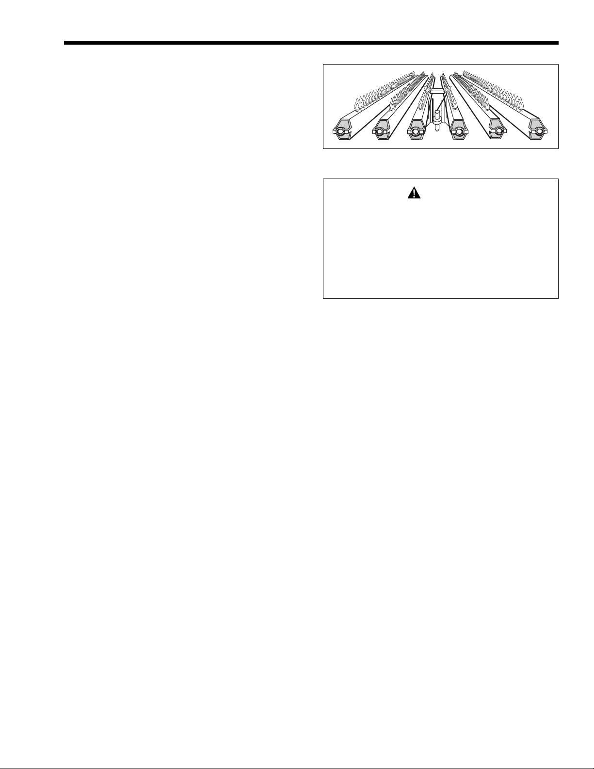
2. At start-up and every six (6) months thereafter, the
pilot and main burner fl ame should be observed for
proper performance (see Figure 16). See attached
lighting and shut-down instructions for proper
pilot fl ame pattern. If fl ame has the appearance of
"sooting" tips, check for debris near orifi ces and
call the Laars Service Department.
3. Inspect the venting system for obstruction, leakage
and corrosion at least once each year.
4. Keep heater area clear and free from combustible
material, gasoline and other fl ammable vapors and
liquids (see Table 1 for minimum clearances).
5. Be certain all combustion air and ventilation
openings in the room are unobstructed.
6. Check for fouling on the external surfaces of
the heat exchanger every six months. (NOTE:
after installation and fi rst start-up, check the heat
exchanger for fouling after the following periods of
operation: 24 hours, 7 days, 30 days, 90 days and
once every six months thereafter.)
Fouling on the external surfaces of the heat
exchanger is caused by incomplete combustion and
is a sign of combustion air and/or venting problems.
As soon as any fouling is observed, the cause of
the fouling should be corrected (see Section 5,
Troubleshooting Guide). The heat exchanger can
be checked with a fl ashlight by locating a mirror
under the burners. An alternate method is to remove
the venting and top panels as necessary to inspect
the heat exchanger from above. Also check the
vent system for defects at this time. (If cleaning is
required, shut off all electrical and gas supply to the
heater.)
7. To expose the heat exchanger:
Indoor Models: Remove the fl ue pipe, top of unit,
rear upper jacket, fl ue collector rear panel and heat
exchanger baffl es.
Outdoor Models: Remove vent top assembly,
rear upper jacket, fl ue collector rear panel and heat
exchanger baffl es.
8. To remove all burners:
It is usually more convenient to remove the burner
tray assembly. Disconnect sensor wire, ignition
cable (or thermocouple generator) and pilot gas line.
Disconnect manifold inlet union(s). Remove the four
(4) retaining screws. Grasp the manifold pipe and
slide out the burner tray.
Page 15
Figure 16 - Main Burner Flame Pattern
Caution
Black carbon or green soot on a dirty heat
exchanger can, under certain conditions, be
ignited by a random spark or open fl ame. To
prevent this unlikely occurrence, dampen the
soot deposits with wet brush or fi ne water
spray before servicing or cleaning the heat
exchanger.
9. Clean heat exchanger using a wire brush to remove
soot and loose scale from the unit. Clean fallen
debris from bottom of heater. Make sure burner
ports are clear and pilot assembly is free of debris.
10. Reassemble in reverse order and be sure the heat
exchanger baffl es are replaced.
11. The gas and electric controls installed on the heater
are engineered for both dependable operation
and long life, but the proper functioning of these
components is necessary for safe operation of the
heater. It is strongly recommended that the basic
items be checked by a competent serviceman
every year and replaced when necessary. The basic
controls are:
a. Water temperature controls.
b. Pilot safety system.
c. Automatic electric gas valve(s)
d. Flow switch.
12. Low water cutoffs should be inspected every six (6)
months, when provided.
NOTE: The warranty does not cover any damage
caused by lack of required maintenance or improper
operating practices.
13. Pool Water Chemistry
Maintain the pool water chemistry in accordance
with generally accepted principles in the swimming
pool industry as stated by NSPI, the CDC or your
local codes.
Page 16

Page 16
LAARS Heating Systems
The general recommendations include keeping
the water chemistry stable within the following
guidelines:
pH: 7.2 to 7.8
Free Available
Chlorine: 2.0 - 4.0 ppm
Total Alkalinity: 80 - 120 ppm
Calcium Hardness: 200 - 400 ppm
Total Dissolved Solids: < 1500 ppm
These values are important to maintaining the
pool equipment in proper operating condition and
preventing corrosion, liming or other problems.
Proper pool water chemistry includes other values
that must be maintained for swimmer safety. Refer
to your local agency having jurisdiction, NSPI
(National Spa and Pool Institute), the CDC (Centers
for Disease Control), or the WHO (World Health
Organization) for more information.
Section 5
Troubleshooting
For proper service and problem diagnosis of the heater
and heater system, the following tools are required:
a. Gas pressure test kit with range from zero to 14
W.C. Either a slack tube manometer or an accurate
gas pressure gauge is acceptable with proper
adapters to connect to the available fi ttings in the
line and on the gas valve.
b. Multi-meter with the following ranges:
0 to 500 volts A.C.
0 to 1000 ohms continuity
0 to 50 millivolts
0 to 20 microamps
c. Tube cleaning kit consisting of reamer, stainless
steel brush, speed handle and handle extensions.
d. A pool thermometer with a proper range.
e. A pressure gauge with proper range.
Page 17

Mighty Therm Commercial Pool Heating Boiler
Page 17
1. Symptom: heater is pounding, knocking or emitting steam from relief valve
Possible Cause What to Do
A. Low or no water fl ow A. Is the heater wired into the fi lter pump circuit so that the heater cannot fi re
(most likely). unless the pump is running?
Check to see that all valves in system are open to be sure that water can
circulate through the heater.
Check pool fi lter, clean if clogged.
Examine heater pump for clogged or frozen impeller.
Check fl ow switch for proper operation and range setting.
B. Debris from system piping B. Remove header covers. Examine all tubes and waterways. Clean out tubes.
is blocking tubes. Use new gaskets when reassembling.
C. Scale has formed in tubes C. Clean tubes with tube cleaning kit. Determine hardness. Check water fl ow, and
from high mineral content. clean pool fi lter.
2. Symptom: heater will not fi re
A. Heater not getting power. A. Check to see that power switch is "ON." Use testing device to trace power to
heater power source. Check fuse and secondary voltage in heater control.
B. Operating or safety control has B. Turn off power. Check continuity across terminals of each operating and safety
opened circuit to electric gas valve. control switch up to the electric gas valve. Replace defective control.
C. Pilot fl ame is out. C. Relight pilot per instruction.
D. Manual reset device has tripped. D. Reset pilot safety and all manual reset safety switches. Follow instructions for
start-up.
E. No gas pressure to burners. E. Trace gas line to service shutoff cock. If service cock is open, trace gas line to
meter. If no pressure is present at meter, call for public utility service. If gas is
present in heater inlet, check pressures in following sequence: (1) downstream
from pressure regulator; (2) downstream from electric gas valve. Replace or
adjust as necessary.
F. Electric gas valve operator is F. Disconnect wiring harness at gas valve terminals. Check continuity of actuator
burned out or shorted. coil. If open circuit or short is indicated, replace coil or operator.
G. Pump does not run. G. Operate in manual. Check power to pump from relay, Check that pump/motor is
free to rotate. Replace relay or motor as necessary.
H. Pump runs, but fl ow switch H. Check continuity across fl ow switch. Inspect paddle for proper movement.
not closing. Adjust fl ow range setting.
I. Field interlock open. I. Jumper terminals and isolate problem in other equipment.
3. Symptom: pressure relief valve leaking intermittently or steadily
A. Faulty relief valve. A. Replace with a new relief valve with proper setting (see rating plate).
4. Symptom: soot in fl ueways or in tubes, or noxious fumes from bad combustion
A. Combustion air supply to heater A. Check air supply opening. Look for debris in screen or louvre which covers
room is inadequate. combustion air opening, or for objects blocking the opening.
B. Stack or vent is blocked or restrictive. B. Look for blocked stack and excessive number of elbows in stack or excessive
length of horizontal runs.
C. Severe downdraft is causing C. Check for (1) proper vent cap on stack; (2) adequate height of stack above
spillage of fl ue products into room. roof; (3) equipment exhausting air from inside of building; and (4) proper
installation of draft diverter.
D. Gas pressure to burners is excessive. D. Check gas pressure with manometer, and adjust with heater fi ring at full rate.
E. Heater not fi tted for the fuel supplied. E. See nameplate for correct fuel.
F. Heater installed at high altitude F. Installations at altitudes in excess of 2000 ft. above sea level are subject to
without proper derating. jurisdiction of the local inspection authorities. Check orifi ce size, contact your
dealer or factory for proper size.
5. Symptom: water dripping in fi rebox
A. Tube in heat exchanger has A. Tube failure is almost always caused by scale formation in the tube, or
overheated and ruptured. inadequate water fl ow through the heater.
B. Heater is condensing from low B. Check bypass valve adjustment.
inlet temperature.
Page 18

Page 18
LAARS Heating Systems
Section 6 Parts Description and Order Numbers
Jacket and Combustion Chamber Components
1 Top Panel Assembly 10535701 10535702 10535703 10535704 10535705 10535706 10535707 10535708 10535709
2 Spacer, Flue Collector - - - 10540800 10540800 10540800 10540800 10540800 10540800
3 End Panel, Flue Collector, Left 10533700 10533700 10533700 10533700 10533700 10533700 10533700 10533700 10533700
4 End Panel, Flue Collector, Right 10533800 10533800 10533800 10533800 10533800 10533800 10533800 10533800 10533800
5 Rear Panel, Flue Collector {Indoor} 10535501 10535502 10535503 10535504 10535505 10535506 10535507 10535508 10535509
6 Front Support, Flue Collector {Indoor} 10534401 10534402 10534403 10534404 10534405 10534406 10534407 10662108 10662109
7 Tile Cover, Front/Rear {Indoor} 10534201 10534202 10534203 10534204 10534205 10534206 10534207 10661508 10661509
(2) (2) (2) (4) (4) (4) (4) (4) (4)
8 Tile Heat Shield/Spacer, 10560100 - - - - - - - -
Front and Rear (2)
9 Tile Heat Shield/Spacer, Front - 10547901 10547902 - - 10547903 10547901 10547904 10547903
10 Tile Heat Shield/Spacer, Front - - - 10548002 10548003 - - - 10548001
11 Tile Heat Shield/Spacer, Front - - - - - 10548101 10548102 10548103 10548104
12 Tile Heat Shield/Spacer, Rear - 10548201 10548202 - - 10548203 10548201 10548204 10548203
13 Tile Heat Shield/Spacer, Rear - - - 10548302 10548303 - - - 10548301
14 Tile Heat Shield/Spacer, Rear - - - - - 10548401 10548402 10548403 10548404
15 Saddle Assembly, End Tile 10533600 10533600 10533600 10533600 10533600 10533600 10533600 10533600 10533600
(2) (2) (2) (2) (2) (2) (2) (2) (2)
16 Lower End Panel/ 10540701 10540701 10540701 10540701 10540701 10540701 10540701 10540701 10540701
Heat Shield Weldment, Right
17 Lower End Panel/ 10540702 10540702 10540702 10540702 10540702 10540702 10540702 10540702 10540702
Heat Shield Weldment, Left
18 Lower Rear Panel 10532901 10532902 10532903 10532904 10532905 10532906 10532907 10532908 10532909
Weldment
19 Middle Rear Panel/ 10540401 10540402 10540403 10540404 10540405 10540406 10540407 10540408 10540409
Heat Shield Weldment
20 End Panel, Upper Right 10531600 10531600 10531600 10531600 10531600 10531600 10531600 10531600 10531600
21 End Panel, Upper Left 10534000 10534000 10534000 10534000 10534000 10534000 10534000 10534000 10534000
22 Upper Rear Panel/ 10540501 10540502 10540503 10540504 10540505 10540506 10540507 10540508 10540509
Heat Shield Weldment
23 Front Panel, Upper 10531501 10531502 10531503 10531504 10531505 10531506 10531507 10531508 10531509
Key Description Size Size Size Size Size Size Size Size Size
No 500 600 715 850 1010 1200 1430 1670 1825
24 Bracket, Support, End Tile 10551000 10551000 10551000 10551000 10551000 10551000 10551000 10551000 10551000
(2) (2) (2) (2) (2) (2) (2) (2) (2)
NOTE: Numbers in ( ) represent quantity required for each size. Quantity is one otherwise.
Page 19
Mighty Therm Commercial Pool Heating Boiler
Page 19
ONE PIECE
PUMP VOLUTE
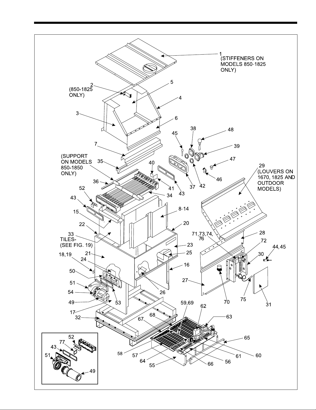
Figure 17. Parts Identifi cation.
Page 20

Page 20
LAARS Heating Systems
25 Drafthood, Relief Baffl e, Right 10540901 10540902 10540903 10540904 10540905 10540906 10540907 10540908 10540909
26 Drafthood, Relief Baffl e, Left 10541001 10541002 10541003 10541004 10541005 10541006 10541007 10541008 10541009
27 Lower Front Panel/ 10554601 10554602 10554603 10554604 10554605 10554606 10554607 10554608 10554609
Heat Shield Weldment
28 Middle Front Panel {Indoor} 10554401 10554402 10554403 10554404 10554405 10554406 10554407 10662008 10662009
29 Sweep Sheet, Flue Collector {Indoor} 10533901 10533902 10533903 10533904 10533905 10533906 10533907 10662208 10662209
30 Control Box Weldment 10545800 10545800 10545800 10545800 10545800 10545800 10545800 10545800 10545800
31 Control Box Cover {Indoor} 10547200 10547200 10547200 10547200 10547200 10547200 10547200 10547200 10547200
32 Base/Tile Support Assembly {Indoor} 10536901 10536902 10536903 10536904 10536905 10536906 10536907 10536908 10536909
33 Tile Assemblies {Refer to Figure 18 for confi gurations and Part Numbers}
Optional Items
Non-Combustible Base {Rail} 10539000 10539000 10539000 10539000 10539000 10539000 10539000 10539000 10539000
(2) (2) (2) (2) (2) (2) (2) (2) (2)
Water System
34 8-Tube Assembly, Copper Tubes/ 10534701 10534702 10534703 10534704 10534705 10534706 10534707 — —
Cast Iron Tubs {Indoor}
8-Tube Assembly, Copper Tubes/ 10542901 10542902 10542903 10542904 10542905 10542906 10542907 — —
Bronze Tubs {Indoor}
8-Tube Assembly, CU-NI Tubes/ 10553601 10553602 10553603 10553604 10553605 10553606 10553607 — —
Cast Iron Tubs {Indoor}
8-Tube Assembly, CU-NI Tubes/ 10553701 10553702 10553703 10553704 10553705 10553706 10553707 — —
Bronze Tubs {Indoor}
10-Tube Assembly, Copper Tube/ — — — — — — — 10665908 10665909
Cast Iron Tubs {Indoor}
10-Tube Assembly, Copper Tube/ — — — — — — — 20001108 20001109
Bronze Tubs {Indoor}
10-Tube Assembly, CU-NI Tubes/ — — — — — — — 20001008 20001009
Cast Iron Tubs {Indoor}
10-Tube Assembly, CU-NI Tubes/ — — — — — — — 10670408 10670409
Bronze Tubs {Indoor}
35 Baffl e, Heat Exchanger Front/ 10534301 10534302 10534303 10534304 10534305 10534306 10534307 20020108 20020109
Key Description Size Size Size Size Size Size Size Size Size
No 500 600 715 850 1010 1200 1430 1670 1825
Rear {Indoor} (2) (2) (2) (4) (4) (4) (4) (4) (4)
NOTE: Numbers in ( ) represent quantity required for each size. Quantity is one otherwise.
Page 21

Mighty Therm Commercial Pool Heating Boiler
Page 21
36 Baffl e, Heat Exchanger {8-Tube} 10534601 10534602 10534603 10534604 10534605 10534606 10534607 — —
(7) (14) (14) (14) (14) (28) (28) — —
Baffl e, Heat Exchanger {10-Tube} — — — — — — — 10667708 10667709
(28) (14)
Baffl e, Heat Exchanger {10-Tube} — — — — — — — — 10667702
(14)
37 Inlet/Outlet Header, Machined 10364500 10364500 10364500 10364500 10364500 10364500 10364500 10364500 10364500
{S0094300 Glassed Cast Iron}
Inlet/Outlet Header, Machined 10364501 10364501 10364501 10364501 10364501 10364501 10364501 10364501 10364501
{S0064000 Bronze}
38 Flange, 2-1/2" NPT Machined 10391303 10391303 10391303 10391303 10391303 10391303 10391303 10391303 10391303
{S0063600 Cast Iron}
Flange, 2-1/2" NPT Machined 10391304 10391304 10391304 10391304 10391304 10391304 10391304 10391304 10391304
{S0064400 Bronze}
39 Tee, Machined Flange 20130002 20130002 20130002 20130002 20130002 20130002 20130002 20130002 20130002
{Glassed Cast Iron}
Tee, Machined Flange {Bronze} 20150303 20150303 20150303 20150303 20150303 20150303 20150303 20150303 20150303
40 Baffl e, Water Inlet 10338300 10338300 10338300 10338300 10338300 10338300 10338300 10338300 10338300
41 Barrier, Water 20230101 20230101 20230101 20230101 20230101 20230101 20230101 20230101 20230101
(2) (2) (2) (2) (2) (2) (2) (2) (2)
42 Flange Gasket S0063700 S0063700 S0063700 S0063700 S0063700 S0063700 S0063700 S0063700 S0063700
(2) (2) (2) (2) (2) (2) (2) (2) (2)
43 Header Gasket w/Barrier S0095100 S0095100 S0095100 S0095100 S0095100 S0095100 S0095100 S0095100 S0095100
(2) (2) (2) (2) (2) (2) (2) (2) (2)
44 Well, Immersion E2074000 E2074000 E2074000 E2074000 E2074000 E2074000 E2074000 E2074000 E274000
45 Well, High Limit E0025900 E0025900 E0025900 E0025900 E0025900 E0025900 E0025900 E0025900 E0025900
46 Valve, Pressure Relief A0063300 A0063300 A0063300 A0063600 A0063600 A0063600 A0063600 A0063600 A0063600
3/4 NPT, 75 PSI
47 Temperature Gauge A2089500 A2089500 A2089500 A2089500 A2089500 A2089500 A2089500 A2089500 A2089500
(2) (2) (2) (2) (2) (2) (2) (2) (2)
48 Flow Switch Kit {Indoor / Outdoor} RE0013000 RE0013000 RE0013000 RE0013000 RE0013000 RE0013000 RE0013000 RE0013000 RE0013000
49 Pump, Motor, Impeller A2001800 A2001800 A2001800 A2001800 A2001800 A2001800 A2001800 A2001800 A2001900
Key Description Size Size Size Size Size Size Size Size Size
No 500 600 715 850 1010 1200 1430 1670 1825
50 Pump Adapter {Glassed Cast Iron} 10364200 10364200 10364200 10364200 10364200 10364200 10364200 10364200 10364200
Pump Adapter {Cast Bronze} 10364201 10364201 10364201 10364201 10364201 10364201 10364201 10364201 10364201
NOTE: Numbers in ( ) represent quantity required for each size. Quantity is one otherwise.
Page 22

Page 22
LAARS Heating Systems
51 Pump Housing {Glassed Cast Iron} 10261501 10261501 10261501 10261501 10261501 10261501 10261501 10261501 10261501
Pump Housing {Bronze} 10483301 10483301 10483301 10483301 10483301 10483301 10483301 10483301 10483301
Casting, Pump Volute S2056900 S2056900 S2056900 S2056900 S2056900 S2056900 S2056900 S2056900 S2056900
52 Baffl e, Diffuser 10338400 10338400 10338400 10338400 10338400 10338400 10338400 10338400 10338400
53 Pump Housing Gasket S0024600 S0024600 S0024600 S0024600 S0024600 S0024600 S0024600 S0024600 S0024600
54 Pump Motor Gasket, A0021400 A0021400 A0021400 A0021400 A0021400 A0021400 A0021400 A0021400 A0021400
Gas System
55 Burner Tray, IID, On/Off, 10550601 10550602 10550603 10550604 10550605 10550606 10550607 10550608 10550609
Single Sect. Manifold {Nat.}
Burner Tray, IID, On/Off, 20097401 20097402 20097403 20097404 20097405 20097406 20097407 20097408 20097409
Single Sect. Manifold {LP}
Burner Tray, St. Pilot, On/Off, 10526201 10526202 10526203 10526204 10526205 10526206 10526207 10526208 10526209
Single Sect. Manifold {Nat.}
Burner Tray, St. Pilot, On/Off, 10529601 10529602 10529603 10529604 10529605 10529606 10529607 10529608 10529609
Single Sect. Manifold {LP}
56 Gas Manifold Weldment 10525901 10525902 10525903 10525904 10525905 10525906 10525907 10525908 10525909
{Single Inlet}
57 Burner, Main L0052300 L0052300 L0052300 L0052300 L0052300 L0052300 L0052300 L0052300 L0052300
58 Pilot Bracket/Burner Weldment 10529502 10529502 10529502 10529502 10529502 10529502 10529502 10529502 10529502
59 Pilot Burner W0035800 W0035800 W0035800 W0035800 W0035800 W0035800 W0035800 W0035800 W0035800
Standing Pilot {Nat.}
Pilot Burner W0034400 W0034400 W0034400 W0034400 W0034400 W0034400 W0034400 W0034400 W0034400
Standing Pilot {LP}
Pilot Burner W0030600 W0030600 W0030600 W0030600 W0030600 W0030600 W0030600 W0030600 W0030600
IID Pilot {Nat.}
Pilot Burner W2001300 W2001300 W2001300 W2001300 W2001300 W2001300 W2001300 W2001300 W2001300
IID Pilot {LP}
60 Orifi ce, Nat. Gas - 4" W.C. L0050700 L0050700 L0050700 L0050700 L0050700 L0050700 L0050700 L0050700 L0050700
{Sea Level} (22) (26) (30) (36) (42) (50) (60) (70) (76)
Orifi ce, Propane - 9" W.C. L0032900 L0032900 L0032900 L0032900 L0032900 L0032900 L0032900 L0032900 L0032900
{Sea Level} (22) (26) (30) (36) (42) (50) (60) (70) (76)
61 Valve, Manual, Gas {Nat.} V0004200 V0004200 V0004200 V0004300 V0004300 V0004300 V0004300 V0004300 V0004300
Key Description Size Size Size Size Size Size Size Size Size
No 500 600 715 850 1010 1200 1430 1670 1825
Valve, Manual, Gas {LP} V0004800 V0004800 V0004800 V0004800 V0004200 V0004200 V0004300 V0004300 V0004300
62 Safety Gas Valve, On-Off {Nat.} V0046600 V0046600 V0046600 V0046600 V0046700 V0046700 V0046700 V0046700 V0046800
NOTE: Numbers in ( ) represent quantity required for each size. Quantity is one otherwise.
Page 23

Mighty Therm Commercial Pool Heating Boiler
Page 23
Safety Gas Valve, On-Off {LP} V0046600 V0046600 V0046600 V0046600 V0046600 V0046600 V0046700 V0046700 V0046700
63 Valve, Gas, Operating/Reg. V0051200 V0051200 V0051200 V0051200 V0051300 V0051300 V0051300 V0051400 V0051400
On-Off {Nat.}
Valve, Gas, Operating/Reg. V0054800 V0054800 V0054800 V0054800 V0054800 V0054800 V0054900 V0054900 V0054900
On-Off {LP}
64 Valve, Pilot, Gas Manual W0002100 W0002100 W0002100 W0002100 W0002100 W0002100 W0002100 W0002100 W0002100
65 Manifold Cover Plate Assembly 10552901 10552902 10552903 10552904 10552905 10552906 10552907 10552908 10552909
{Single Pilot}
66 Burner Anti-Rotation Bracket 10525301 10525302 10525303 10525304 10525305 10525306 10525307 10525308 10525309
{Single Pilot}
67 Burner Tie Down Bracket, Left 10525701 10525702 10525703 10525704 10525705 10525707 10525708 10525709 10525710
{Single Pilot}
68 Burner Tie Down Bracket, Right 10542001 10542002 10542003 10542004 10542005 10542007 10542008 10542009 10542010
{Single Pilot}
69 Thermocouple {Standing Pilot} W0035900 W0035900 W0035900 W0035900 W0035900 W0035900 W0035900 W0035900 W0035900
70 Pilot Solenoid Valve (IID) W0019300 W0019300 W0019300 W0019300 W0019300 W0019300 W0019300 W0019300 W0019300
Man. Reset Pilot Relay (Std. Pilot) W0030000 W0030000 W0030000 W0030000 W0030000 W0030000 W0030000 W0030000 W0030000
Electrical Components
71 Ignition Control, Electronic, E2305500 E2305500 E2305500 E2305500 E2305500 E2305500 E2305500 E2305500 E2305500
U.S. {Nat.}
Ignition Control, Electronic, E2305400 E2305400 E2305400 E2305400 E2305400 E2305400 E2305400 E2305400 E2305400
Single Try
72 Transformer, 115V/24V R0021300 R0021300 R0021300 R0021300 R0021300 R0021300 R0021300 R0021300 R0021300
73 Switch, High Limit, Manual Reset E2103900 E2103900 E2103900 E2103900 E2103900 E2103900 E2103900 E2103900 E2103900
74 Controller, Water Temp. E2103800 E2103800 E2103800 E2103800 E2103800 E2103800 E2103800 E2103800 E2103800
75 Sensor, Water Temp. E2103600 E2103600 E2103600 E2103600 E2103600 E2103600 E2103600 E2103600 E2103600
76 Switch, Limit, Auto Reset E2104800 E2104800 E2104800 E2104800 E2104800 E2104800 E2104800 E2104800 E2104800
77 Water Barrier Assembly 20305103 20305103 20305103 20305103 20305103 20305103 20305103 20305103 20305103
Electrical Components {Optional}
High Gas Pressure Switch E0023300 E0023300 E0023300 E0023300 E0023300 E0023300 E0023300 E0023300 E0023300
Low Gas Pressure Switch E0023500 E0023500 E0023500 E0023500 E0023500 E0023500 E0023500 E0023500 E0023500
Low Water CutOff RE2075100 RE2075100 RE2075100 RE2075100 RE2075100 RE2075100 RE2075100 RE2075100 RE2075100
Key Description Size Size Size Size Size Size Size Size Size
No 500 600 715 850 1010 1200 1430 1670 1825
Vent Valve 120 Volts {System 4} V0019000 V0019000 V0019000 V0019000 V0019000 V0019000 V0019000 V0019000 V0019000
Vent Valve 24 Volts {System 9, 11} V2000100 V2000100 V2000100 V2000100 V2000100 V2000100 V2000100 V2000100 V2000100
NOTE: Numbers in ( ) represent quantity required for each size. Quantity is one otherwise.
Page 24
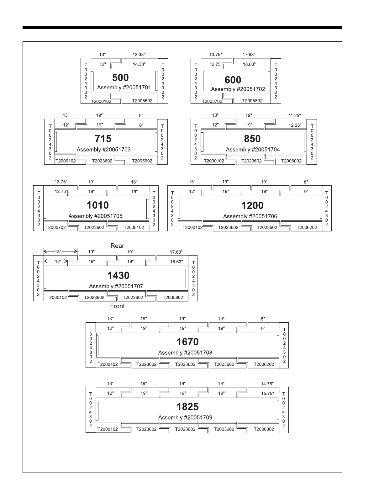
Page 24
LAARS Heating Systems
When ordering tiles: Assembly number is
for all tiles. Part numbers shown for the front
of unit are the same for the rear tiles. Check
dimensions of old tile as shown here to
confirm part number.
Figure 18 - Tile Assemblies
Page 25
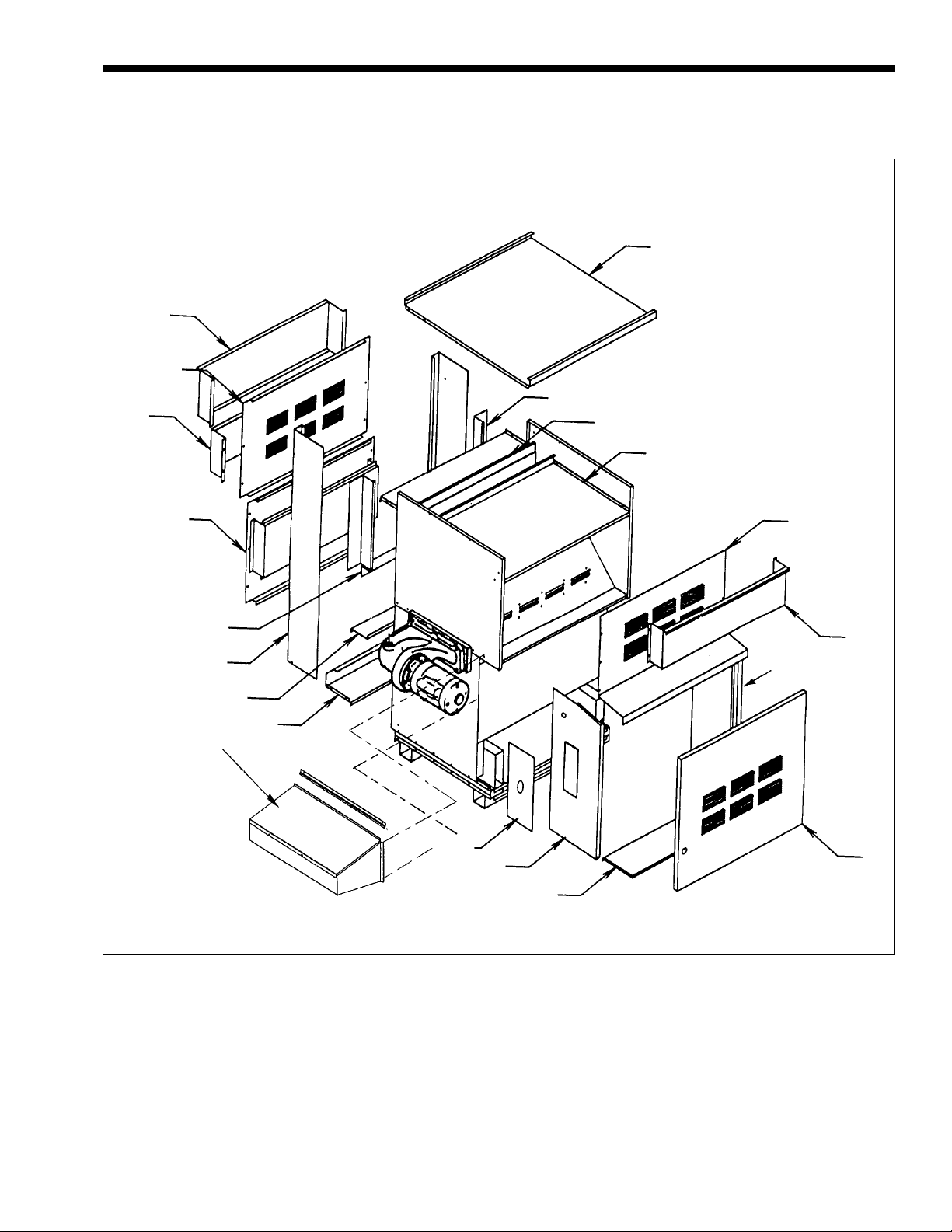
Mighty Therm Commercial Pool Heating Boiler
2
4
3
Page 25
1
5
19
18
7
6
8
9
10
20
Figure 19 - Outdoor Parts
11
12
17
16
13
15
14
Page 26

Page 26
LAARS Heating Systems
Outdoor Jacket, Combustion Chamber, Heat Exchanger Components
Refer To Figure 19 For Placement
5 Rear Panel, Flue Collector {Outdoor} 10661701 10661702 10661703 10661704 10661705 10661706 10661707 10661708 10661709
6 Front Support, Flue Collector 10662101 10662102 10662103 10662104 10662105 10662106 10662107 10662108 10662109
{Outdoor}
7 Tile Cover, Front/Rear {Outdoor} 10661501 10661502 10661503 10661504 10661505 10661506 10661507 10661508 10661509
(2) (2) (2) (4) (4) (4) (4) (4) (4)
28 Middle Front Panel {Outdoor} 10662001 10662002 10662003 10662004 10662005 10662006 10662007 10662008 10662009
29 Sweep Sheet, Flue Collector 10662201 10662202 10662203 10662204 10662205 10662206 10662207 10662208 10662209
{Outdoor}
31 Control Box Cover {Outdoor} 10630300 10630300 10630300 10630300 10630300 10630300 10630300 10630300 10630300
32 Non-Combustible Base/Tile 10602301 10602302 10602303 10602304 10602305 10602306 10602307 10602308 10602309
Support Assembly {Outdoor}
34 10-Tube Assembly, 10665901 10665902 10665903 10665904 10665905 10665906 10665907 10665908 10665909
Copper Tube/Cast Iron Tubs {Outdoor}
10-Tube Assembly, 20001101 20001102 20001103 20001104 20001105 20001106 20001107 20001108 20001109
Copper Tube/Bronze Tubs {Outdoor}
10-Tube Assembly, 20001001 20001002 20001003 20001004 20001005 20001006 20001007 20001008 20001009
CU-NI Tubes/ Cast Iron Tubs {Outdoor}
10-Tube Assembly, 10670401 10670402 10670403 10670404 10670405 10670406 10670407 10670408 10670409
CU-NI Tubes/ Bronze Tubs {Outdoor}
35 Baffl e, Heat Exchanger Front/Rear 20020101 20020102 20020103 20020104 20020105 20020106 20020107 20020108 20020109
{Outdoor} (2) (2) (2) (2) (2) (2) (2) (2) (2)
36 Baffl e, Heat Exchanger, 10-Tube 10667701 10667702 10667703 10667704 10667705 10667706 10667707 10667708 10667709
(7) (14) (14) (14) (14) (28) (28) (28) (14)
Baffl e, Heat Exchanger, 10-Tube — — — — — — — — 10667702
(14)
Refer To Figure 19 For Placement
1 Top Panel 10660701 10660702 10660703 10660704 10660705 10660706 10660707 10660708 10660709
2 Rear Windshield 10658101 10658102 10658103 10658104 10658105 10658106 10658107 10658108 10658109
3 Upper Rear Louver shield 10657101 10657102 10657103 10657104 10657105 10657106 10657107 10657108 10657109
Key Description Size Size Size Size Size Size Size Size Size
No 500 600 715 850 1010 1200 1430 1670 1825
NOTE: Numbers in ( ) represent quantity required for each size. Quantity is one otherwise.
Page 27

Mighty Therm Commercial Pool Heating Boiler
Page 27
4 Upper Rear Panel 10658701 10658702 10658703 10658704 10658705 10658706 10658707 10658708 10658709
5 Gap Closure-Side 10660200 10660200 10660200 10660200 10660200 10660200 10660200 10660200 10660200
(2) (2) (2) (2) (2) (2) (2) (2) (2)
6 Gap Closure-Middle 10660101 10660102 10660103 10660104 10660105 10660106 10660107 10660108 10660109
7 Lower Rear Panel Assembly 10660501 10660502 10660503 10660504 10660505 10660506 10660507 10660508 10660509
8 Rear End Panel Left and Right 10657700 10657700 10657700 10657700 10657700 10657700 10657700 10657700 10657700
(2) (2) (2) (2) (2) (2) (2) (2) (2)
9 Lower Rear Shield-Inner 10659901 10659902 10659903 10659904 10659905 10659906 10659907 10659908 10659909
10 Rear Base Extension 10658501 10658502 10658503 10658504 10658505 10658506 10658507 10658508 10658509
11 Gas Train Interface Plate 20050200 20050200 20050200 20050200 20050200 20050200 20050200 20050200 20050200
12 Left Front End Panel 10657501 10657501 10657501 10657501 10657501 10657501 10657501 10657501 10657501
13 Right Front End Panel 10657502 10657502 10657502 10657502 10657502 10657502 10657502 10657502 10657502
14 Front Base Extension 10659701 10659702 10659703 10659704 10659705 10659706 10659707 10659708 10659709
15 Door Panel Weldment 20050401 20050402 20050403 20050404 20050405 20050406 20050407 20050408 20050409
Left Door Panel Weldment — — — — 20100705 20100706 20100707 20100708 20100709
16 Front Windshield 10659101 10659102 10659103 10659104 10659105 10659106 10659107 10659108 10659109
17 Upper Front Panel 10658901 10658902 10658903 10658904 10658905 10658906 10658907 10658908 10658909
18 Flue Panel Front 10659501 10659502 10659503 10659504 10659505 10659506 10659507 10659508 10659509
19 Flue Panel Rear 10659301 10659302 10659303 10659304 10659305 10659306 10659307 10659308 10659309
Key Description Size Size Size Size Size Size Size Size Size
No 500 600 715 850 1010 1200 1430 1670 1825
20 Pump Cover Assembly 20050100 20050100 20050100 20050100 20050100 20050100 20050100 20050100 20050100
NOTE: Numbers in ( ) represent quantity required for each size. Quantity is one otherwise.
Page 28

800.900.9276 • Fax 800.559.1583 (Customer Service, Service Advisors)
20 Industrial Way, Rochester, NH 03867 • 603.335.6300 • Fax 603.335.3355
1869 Sismet Road, Mississauga, Ontario, Canada L4W 1W8 • 905.238.0100 • Fax 905.366.0130
www.Laars.com Litho in U.S.A. © Laars Heating Systems 0806 Document 3006T
H0067300T
 Loading...