

Page 1

BOGE CM9
Deutsch
English
Français
Italiano
Español
Nederlands
5.963-38
7.0 08/09
Page 2

Page 3

Betriebsanleitung
SchraubenkompressorModul
Baureihe CM 9
Page 4

Inhaltsverzeichnis1
Betriebsanleitung
für Schraubenkompressor-Modul
– CM 9
BOGE KOMPRESSOREN
Postfach 10 07 13
33507 Bielefeld
Otto-Boge-Straße 1–7
33739 Bielefeld
Fon: 0 52 06 / 6 01-0
Fax: 0 52 06 / 6 01-200
Mail: info@boge.com
Net: www.boge.com
BOGE Betriebsanleitung für Schraubenkompressor-Modul Baureihe CM 9
Inhalt.pm6.5 - D
Stand: 07/ 2009
Nr. 596.0696.00
Schutzgebühr: € 5,00
Seite I
Page 5

Inhaltsverzeichnis1
Seite II BOGE Betriebsanleitung für Schraubenkompressor-Modul Baureihe CM 9
Inhalt.pm6.5 - D
Page 6

Inhalt
Inhaltsverzeichnis1
Teil 1:
Allgemeines
Teil 2:
Produktbeschreibung
1.1 Allgemeine Sicherheitshinweise.................................................1.1
Sicherheitshinweise für den Betrieb des Kompressors .................. 1.1
Sicherheitshinweise für Wartung und Reparatur des Kompressors 1.2
Unfallverhütungsvorschriften ..........................................................1.2
1.2 Einleitung ...................................................................................... 1.3
Verwendete Symbole .....................................................................1.3
Symbole am Kompressor ............................................................... 1.4
Bestimmungsgemäße Verwendung ................................................1.4
Unzulässige Verwendung ............................................................... 1.4
Transportschäden ........................................................................... 1.5
Daten auf dem Typenschild ............................................................1.5
Service ...........................................................................................1.5
2.1 Technische Daten ......................................................................... 2.1
Technische Daten CM 9 Kompaktmodul, Teil 1 ..............................2.1
Technische Daten CM 9 Kompaktmodul, Teil 2 ..............................2.2
2.2 Funktionsbeschreibung............................................................... 2.3
Funktionsprinzip der Kompressorstufe ........................................... 2.3
Luftkreislauf .................................................................................... 2.3
Ölkreislauf ...................................................................................... 2.4
2.3 Regelung des Kompressors........................................................2.5
Netzdruck .......................................................................................2.5
Betriebszustände ...........................................................................2.5
Kurze Betriebszeiten ......................................................................2.5
2.4 Regeleinrichtungen ...................................................................... 2.6
Steuerung Betriebsdruckschalter ................................................... 2.6
2.5 Sicherheits- und Überwachungseinrichtungen .........................2.7
Allgemeines.................................................................................... 2.7
Sicherheits-Temperaturbegrenzung ............................................... 2.7
Sicherheitsventil .............................................................................2.7
Antrieb und Aufbau ........................................................................2.7
2.6 Abmessungen ..............................................................................2.8
Teil 3:
Aufstellung
BOGE Betriebsanleitung für Schraubenkompressor-Modul Baureihe CM 9
Inhalt.pm6.5 - D
3.1 Transport.......................................................................................3.1
Allgemeines.................................................................................... 3.1
Seite III
Page 7

Inhaltsverzeichnis1
3.2 Der Betriebsraum ......................................................................... 3.2
Aufstellungs-, Wartungsbedingungen und Verwendungszweck
für untergebaute und separat angeordnete Druckbehälter ............. 3.2
Brandschutz ................................................................................... 3.2
Schallschutz ...................................................................................3.2
Zulässige Umgebungseinflüsse...................................................... 3.3
Be- und Entlüftung .........................................................................3.3
Kühlluftbedarf (bei Luftkühlung) .....................................................3.4
Entsorgung des anfallenden Kondensats .......................................3.4
3.3 Montage ........................................................................................ 3.5
Allgemeines.................................................................................... 3.5
Lieferumfang prüfen .......................................................................3.5
Ölstand prüfen................................................................................ 3.5
3.4 Inbetriebnahme ............................................................................3.6
Drehrichtung prüfen .......................................................................3.6
Dichtigkeit prüfen............................................................................ 3.6
Inbetriebnahme nach längerem Stillstand ......................................3.6
Teil 4:
Wartung
4.1 Sicherheitshinweise..................................................................... 4.1
4.2 Allgemeines ..................................................................................4.2
Wartung durch den BOGE-Service ................................................ 4.2
Übersicht der regelmäßigen Wartungsarbeiten ..............................4.2
Wartungsintervalle .........................................................................4.3
Allgemeine Hinweise zu den verwendeten Schmiermitteln ............ 4.4
Entsorgung verbrauchter Betriebsstoffe ......................................... 4.5
Ersatz- und Verschleißteile ............................................................. 4.5
4.3 Regelmäßige Wartungsarbeiten .................................................. 4.6
Ansaugfilter reinigen bzw. wechseln ............................................... 4.6
Filtereinsatz reinigen ......................................................................4.6
Ölstand kontrollieren, Öl nachfüllen................................................ 4.7
Ölfilter wechseln ............................................................................. 4.8
Ölabscheider wechseln .................................................................. 4.9
Öl wechseln.................................................................................... 4.9
Ölkreislauf spülen......................................................................... 4.11
Druckluft-Öl-Kühler reinigen .........................................................4.11
Sicherheitsventil prüfen ................................................................4.12
4.4 Ersatzteile und Zusatzausstattungen .......................................4.13
Liste der Ersatz- und Verschleißteile (für Wartung) ...................... 4.13
Liste der erhältlichen Zusatzausstattungen ..................................4.13
Teil 5:
Anhang
Seite IV BOGE Betriebsanleitung für Schraubenkompressor-Modul Baureihe CM 9
5.1 Fließschema .................................................................................5.1
Luftgekühlte Ausführung, Standard ................................................ 5.1
5.2 Liste der Wartungs- und Servicearbeiten ...................................5.2
Inhalt.pm6.5 - D
Page 8

Allgemeines
1.1 Allgemeine Sicherheitshinweise
Die Nichtbeachtung der folgenden Sicherheitshinweise kann zu körperlichen Verletzungen und zu Beschädigungen des Kompressors führen.
Beachten Sie neben den Hinweisen in dieser Betriebsanleitung auch
die allgemeingültigen Sicherheits- und Unfallverhütungsvorschriften!
Sicherheitshinweise
für den Betrieb
des Kompressors
1. Der Kompressor darf erst nach Kenntnisnahme dieser Betriebsanleitung
in Betrieb genommen und gewartet werden.
2. Der Kompressor darf nur seiner Bestimmung gemäß, wie in dieser Betriebsanleitung beschrieben, verwendet werden.
3. Der Betreiber hat sicherzustellen
– daß nur entsprechend unterwiesenes und autorisiertes Personal an
diesem Kompressor arbeitet,
– daß das Bedienungs-, Wartungs- und Instandhaltungspersonal gründ-
lich mit allen Sicherheitshinweisen vertraut gemacht worden ist und
daß sie beachtet werden,
– daß der Kompressor immer nur in betriebssicherem Zustand betrie-
ben wird.
4. Beim Betrieb des Kompressors ist jede Arbeitsweise zu unterlassen, die
die Sicherheit am Kompressor beeinträchtigt.
5. Ein Überschreiten des auf dem Typenschild angegebenen Grenzwertes
für den Verdichtungsenddruck ist unzulässig.
6. Der Betrieb des Kompressors ohne die zugehörigen Schutz- und Sicherheitseinrichtungen ist nicht erlaubt.
Eingebaute Sicherheitseinrichtungen dürfen nicht demontiert oder außer
Betrieb gesetzt werden.
Alle Sicherheitsverkleidungen und Türen müssen vor Inbetriebnahme des
Kompressors verschlossen sein und dürfen während des Betriebes nicht
geöffnet werden.
7. Bei Demontage von Sicherheitsverkleidungen oder Sicherheitseinrichtungen für Reparatur oder Wartung ist der Kompressor, wie in der Betriebsanleitung beschrieben, außer Betrieb zu setzen. Unmittelbar nach
Abschluß der Reparatur- oder Wartungsarbeiten sind die Verkleidungen
und Sicherheitseinrichtungen wieder zu montieren und zu verschließen.
8. Der Kompressor darf nur mit den vom Hersteller empfohlenen oder von
ihm genehmigten Zusatzausstattungen (Optionen) betrieben werden.
9. Umbauten und Veränderungen des Kompressors dürfen nur mit Genehmigung von BOGE und unter Beachtung aller einschlägigen Sicherheitsvorschriften vorgenommen werden.
Eigenmächtige Veränderungen des Kompressors schließen eine Haftung
des Herstellers für daraus resultierende Schäden aus.
10. Der Kompressor darf niemals in Betrieb genommen werden, wenn ein
oder mehrere Teile (z.B. Kabel, Stecker) beschädigt sind, die Funktion
nicht einwandfrei ist, Beschädigungen erkennbar oder zu vermuten
sind.
11. Beachten Sie alle direkt am Kompressor angebrachten Sicherheits- und
Gefahrenhinweise!
12. Der Druckluft-Öl-Behälter unterliegt der Druckgeräterichtlinie und muß in
den vorgeschriebenen Abständen überprüft werden.
BOGE Betriebsanleitung für Schraubenkompressor-Modul Baureihe CM 9
Allgemeines.pm6.5 - D
Seite 1.1
Page 9
Allgemeines
1.1 Allgemeine Sicherheitshinweise
Sicherheitshinweise für
Wartung und Reparatur
des Kompressors
1. Wartungsarbeiten dürfen nur von entsprechend unterwiesenen Personen
durchgeführt werden.
2. Einstellungen, Störungsbeseitigungen und Reparaturen dürfen nur von
Fachkräften bzw. entsprechend unterwiesenen Personen durchgeführt
werden.
3. Vor Wartungs- oder Reparaturarbeiten:
– Hauptschalter ausschalten.
– Hauptschalter gegen unbeabsichtigtes Wiedereinschalten sichern.
– Prüfen, ob alle stromführenden Teile elektrisch spannungsfrei sind.
– Kompressor vom Druckluftnetz trennen (druckführende Leitungen
entlasten oder absperren).
4. Bei Reparatur- oder Wartungsarbeiten, bei denen der Kompressor betriebsbereit sein muß, ist insbesondere Vorsicht geboten.
Es muß sichergestellt sein, daß sich auf keinen Fall Personen im Gefahrenbereich aufhalten.
5. Arbeiten an der elektrischen Ausrüstung des Kompressors dürfen nur
von qualifizierten Elektro-Fachkräften ausgeführt werden.
6. Arbeiten an unter Spannung stehenden elektrischen Teilen und Einrichtungen sind nicht zulässig. Ausnahmen regeln die entsprechenden Vorschriften, z.B. DIN VDE 0105.
7. Bei Reparatur oder Wartung dürfen nur die von BOGE zur Verwendung freigegebenen Original-Ersatzteile, Kompressorenöle und
Betriebsstoffe verwendet werden.
Unfallverhütungsvorschriften
8. Der Bediener ist verpflichtet, den Kompressor täglich auf äußerlich erkennbare Schäden und Mängel zu prüfen und eingetretene Veränderungen (einschließlich des Betriebsverhaltens) sofort zu melden.
9. Bei aktiviertem Automatischem Wiederanlauf (Auto-Restart) läuft der
Kompressor nach einem Spannungsausfall selbsttätig wieder an.
Voraussetzung: Der Netzdruck ist kleiner als der eingestellte Einschaltdruck.
Der Betreiber einer Kompressoranlage trägt die Verantwortung dafür, daß
diese ordnungsgemäß aufgestellt, bedient und gewartet wird.
Betreiber in der Bundesrepublik Deutschland müssen vor der Inbetriebnahme
die aktuell gültigen Vorschriften des Hauptverbandes der gewerblichen Berufsgenossenschaften lesen. Neben anderen Vorschriften gilt insbesondere
die Betriebssicherheitsverordnung (BetrSichV).
Die Vorschriften sind bei folgenden Stellen erhältlich:
Berufsgenossenschaft
Carl-Heymanns-Verlag KG, Luxemburger Straße 449, 50939 Köln
Beuth Verlag GmbH, Burggrafenstraße 6, 10787 Berlin
Beim Betrieb der Kompressoranlage außerhalb der Bundesrepublik Deutschland sind neben den Angaben in dieser Betriebsanleitung die Unfallverhütungsvorschriften des Betreiberlandes zu beachten. Werden in diesen Vorschriften Maßnahmen gefordert, die über die gesetzlichen Vorschriften der
Bundesrepublik Deutschland oder über die Angaben in dieser Betriebsanleitung hinausgehen, so sind diese vor Inbetriebnahme der Kompressoranlage
unbedingt durchzuführen.
Seite 1.2
BOGE Betriebsanleitung für Schraubenkompressor-Modul Baureihe CM 9
Allgemeines.pm6.5 - D
Page 10
Allgemeines
1. 2 Einleitung
Der Zweck dieser Betriebsanleitung soll sein, den Kompressor in seiner
Funktion und allen seinen Nutzungsmöglichkeiten kennenzulernen.
Diese Betriebsanleitung enthält wichtige Hinweise, den Kompressor sicher,
wirtschaftlich und seiner Bestimmung gemäß zu betreiben. Ihre Beachtung
hilft, Gefahren zu vermeiden, Reparaturkosten und Ausfallzeiten zu verringern und die Zuverlässigkeit und Lebensdauer des Kompressors zu steigern.
Sie enthält wichtige Informationen zu den erforderlichen Wartungs- und Instandhaltungsmaßnahmen, gibt Hilfestellung im Fall von Betriebsstörungen
und enthält Angaben über Ersatz- und Verschleißteile.
Die Betriebsanleitung muß für das Bedienpersonal ständig am Einsatzort
des Kompressors verfügbar sein.
Die Betriebsanleitung ist von jeder Person sorgfältig zu lesen und anzuwenden, die beauftragt ist, an dem Kompressor folgende Arbeiten durchzuführen:
– Bedienung, einschließlich Störungsbehebung und täglicher Pflege
– Instandhaltung (Wartung, Inspektion, Reparatur)
– Inbetriebnahme
– Transport
Verwendete Symbole
Der Kompressor und seine Zusatzausstattungen dürfen erst nach Kenntnisnahme der Betriebsanleitung montiert und in Betrieb genommen werden.
Die Betriebsanleitung ist geeignet, Anweisungen aufgrund bestehender nationaler Vorschriften zur Unfallverhütung und zum Umweltschutz zu ergänzen.
In den Abbildungen ist der Kompressor zur besseren Ansicht teilweise ohne
Verkleidungen oder Sicherheitseinrichtungen dargestellt. Der Betrieb ohne
diese Bauteile ist aber dennoch verboten!
In dieser Betriebsanleitung sind wichtige Sicherheitshinweise und Tips durch
die folgenden Symbole besonders gekennzeichnet:
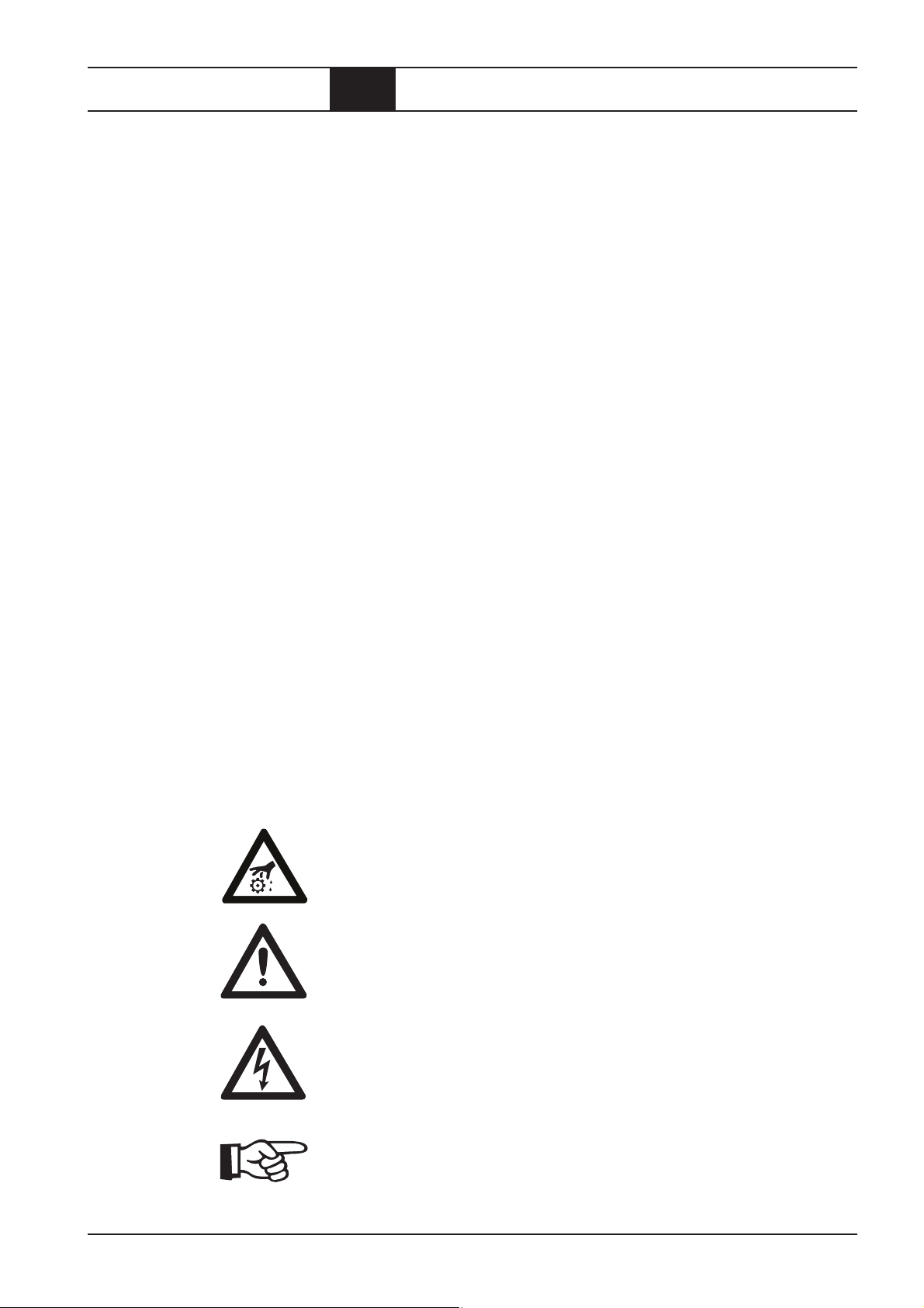
Vorsicht Verletzungsgefahr!
Dieses Symbol warnt vor Gefahren für Leben und Gesundheit des Bedieners oder anderer Personen.
ACHTUNG!
Dieses Symbol warnt vor Gefahren, die die Zerstörung oder Beschädigung
des Kompressors verursachen können.
Achtung Spannung!
Dieses Symbol warnt vor lebensgefährlicher elektrischer Spannung.
Es weist auf Arbeiten hin, die ausschließlich von Elektro-Fachkräften ausgeführt werden dürfen.
Dieses Symbol kennzeichnet Informationen und Tips für den wirtschaftlichen
und schonenden Betrieb des Kompressors.
BOGE Betriebsanleitung für Schraubenkompressor-Modul Baureihe CM 9
Allgemeines.pm6.5 - D
Seite 1.3
Page 11
Allgemeines
1.2 Einleitung
Symbole am
Kompressor
Bestimmungsgemäße
Verwendung
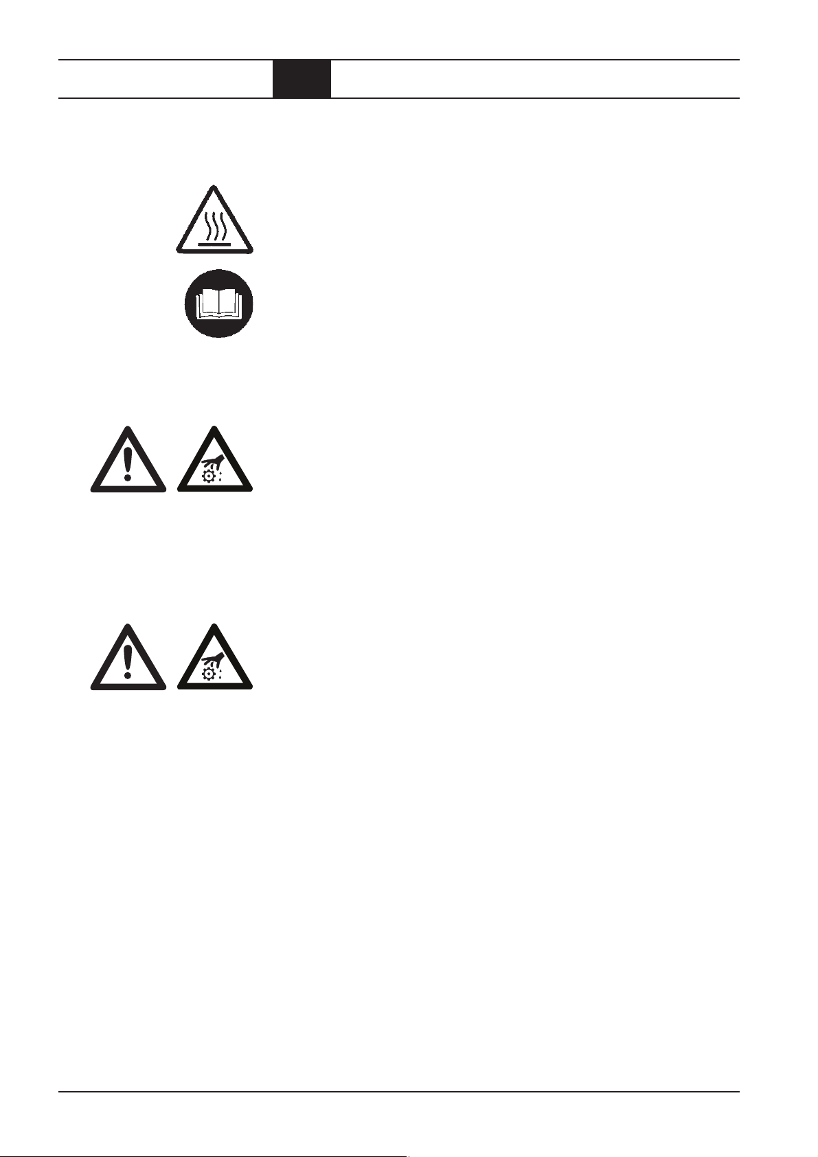
Am Kompressor sind folgende Symbole und Warnhinweise angebracht:
Warnung:
Heiße Oberflächen nicht berühren.
Hinweis:
Anleitungen für das Bedienpersonal müssen gelesen werden.
Das BOGE-Modul CM 9 der Baureihe C einschließlich ihrer Zusatzausstattungen ist ausschließlich für die Verdichtung von Luft vorgesehen.
Die angesaugte Luft darf keine explosionsfähigen oder chemisch instabilen
Gase oder Dämpfe enthalten.
Die angegebene Verdichtungsendtemperatur darf nicht überschritten werden.
Der Anwender hat geeignete Umgebungsbedingungen vorzusehen, in Zweifelsfällen ist die Beratung durch BOGE erforderlich (besonders zu vermeiden
sind hohe Umgebungstemperaturen, Schmutz und Tropfwasser).
Unzulässige
Verwendung
Die erzeugte Druckluft darf niemals auf Personen gerichtet werden.
Es besteht Lebensgefahr!
In die Druckräume des Kompressors wird Öl eingespritzt.
Die erzeugte Druckluft darf nur dann als Atemluft verwendet werden oder
mit Nahrungsmitteln in Berührung kommen, wenn sie vorher aufbereitet
wurde.
Dieser BOGE-Schraubenkompressor ist nicht explosionsgeschützt.
Er darf nicht in EX-Bereichen oder möglicherweise explosiver Atmosphäre
betrieben werden!
Der Kompressor darf nicht in Räumen betrieben werden, in denen starke
Staubbelastungen, giftige oder brennbare Dämpfe und Gase entstehen
können.
Nicht zulässig sind:
– Überschreiten des auf dem Typenschild angegebenen Verdichtungsend-
drucks.
– Veränderungen oder außer Funktion setzen von Sicherheitseinrichtungen.
– Entfernen oder Überlackieren von Schildern und Hinweiszeichen am
Kompressor.
– Bedienung des Kompressors durch nicht berechtigte und nicht unterwie-
sene Personen.
Seite 1.4
BOGE Betriebsanleitung für Schraubenkompressor-Modul Baureihe CM 9
Allgemeines.pm6.5 - D
Page 12
Allgemeines
1. 2 Einleitung
Transportschäden
Daten
auf dem Typenschild
BOGE haftet nicht für Bruch- und Transportschäden. Bitte kontrollieren Sie
sofort nach der Lieferung den Kompressor und reklamieren Schäden beim
letzten Transportführer – auch dann, wenn die Verpackung nicht beschädigt
ist! Zur Sicherung von Ansprüchen gegenüber dem Transportunternehmen
empfehlen wir Ihnen, Maschinen, Geräte und Verpackungsmaterialien vor-
läufig in dem Zustand zu belassen, in dem Sie sie bei der Feststellung des
Schadens vorgefunden haben.
Alle anderen Beanstandungen zeigen Sie uns bitte innerhalb von sechs
Tagen nach dem Eintreffen der Lieferung an.
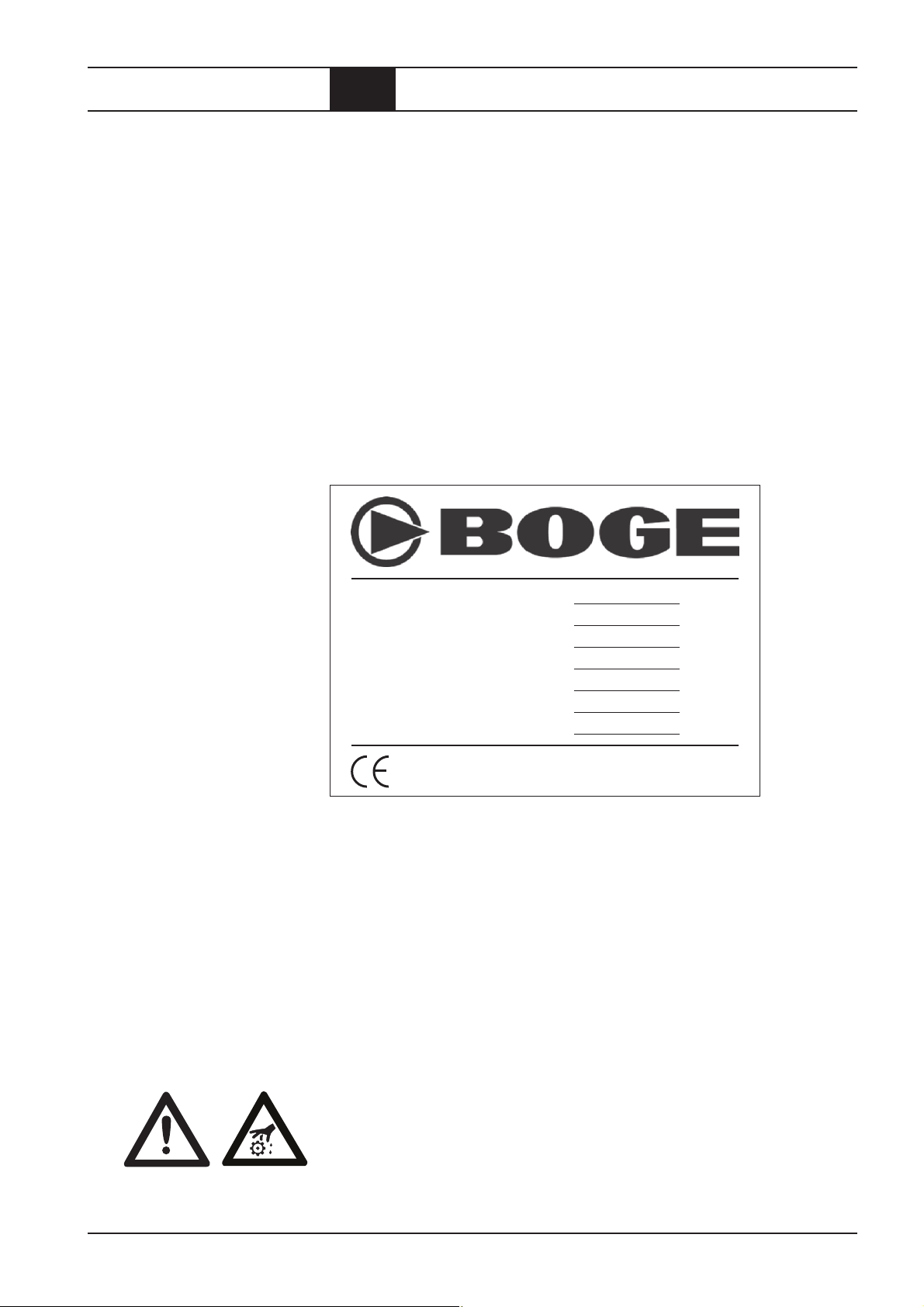
Übertragen Sie die technischen Daten Ihres Kompressors vom Typenschild
oder dem beiliegenden Datenblatt in die untenstehende Abbildung.
Bei Nachfragen haben Sie die wichtigsten Daten so immer zu Hand.
Ty p
Baujahr
Maschinennummer
Volumenstrom m
3
/min
Verdichtungsenddruck bar
Motordrehzahl min
–1
Motorleistung kW
Service
Otto-Boge-Straße 1– 7 · D-33739 Bielefeld · Telefon (0 52 06) 6 01-0
Postfach 100713 · D-33507 Bielefeld · Fax (0 5206) 601-2 00
www.boge.com · info@boge.com
Abb. 1.1: Daten auf dem Typenschild
Der BOGE-Service steht Ihnen bei Fragen selbstverständlich gern zur Verfügung. Rufen Sie an:
0 52 06 / 6 01-0
Um Verzögerungen zu vermeiden, geben Sie uns bei Fragen stets folgende
Daten Ihres Kompressors an:
–Typ
– Baujahr
– Maschinennummer
ACHTUNG!
Während der Gewährleistungszeit dürfen nur BOGE-Servicetechniker oder
Personen, die von BOGE schriftlich beauftragt wurden, das Modul instandsetzen oder ändern. Andernfalls erlöschen alle Gewährleistungsansprüche!
BOGE Betriebsanleitung für Schraubenkompressor-Modul Baureihe CM 9
Allgemeines.pm6.5 - D
Seite 1.5
Page 13

Allgemeines
Seite 1.6
BOGE Betriebsanleitung für Schraubenkompressor-Modul Baureihe CM 9
Allgemeines.pm6.5 - D
Page 14

Produktbeschreibung
2.1 Technische Daten
Technische Daten CM 9 Kompaktmodul, Teil 1
Typ CM 9
Abmessungen
– Breite [mm] 355
– Tiefe [mm] 315
– Höhe [mm] 450
Gewicht
– schallg. [kg] 80
– super-schallg. [kg] –
Höchster Schalldruckpegel [±3 dB(A)]
nach DIN 45635, Teil 13
– schallgedämmt [dB(A)] 61 – 68
Meßflächenmaß
– schallgedämmt [dB(A)] 13
Schalleistungspegel
– schallgedämmt [dB(A)] 74 – 81
Kompressor
max. Verdichtungs-Endtemperatur [°C] 110
Volumenstrom nach
ISO 1217 Anhang C bei:
– p
= 8 bar [m3/min] –
max
– p
= 10 bar [m3/min] 0,340 – 1,100
max
– p
= 13 bar [m3/min] –
max
Antrieb
Nennleistung [kW] 2,2 – 7,5
Nenndrehzahl [min
-1
] 1100 – 4860
BOGE Betriebsanleitung für Schraubenkompressor-Modul Baureihe CM 9
Produkt.pm6.5 - D
Seite 2.1
Page 15

Produktbeschreibung
2.1 Technische Daten
Technische Daten CM 9 Kompaktmodul, Teil 2
Typ CM 9
Ölfüllmengen
Gesamtölfüllmenge [l] 4
Ölnachfüllmenge
zwischen min. + max. [l] 1
Ansauglufttemperatur
– min. [°C] 5
– max. [°C] 40
Kühlluftbedarf (bei Luftkühlung)
– freie Aufstellung [m
– mit Zu- und Abluftkanal [m
3
/h] 800 – 2000
3
/h] –
– freie Lüfterpressung [Pa] –
– freie Lüfterpressung [mm WS] –
Sicherheitsventil
Ansprechdruck:
– p
= 13 bar [bar] 14
max
Seite 2.2
BOGE Betriebsanleitung für Schraubenkompressor-Modul Baureihe CM 9
Produkt.pm6.5 - D
Page 16
Produktbeschreibung
2.2 Funktionsbeschreibung
Funktionsprinzip
der Kompressorstufe
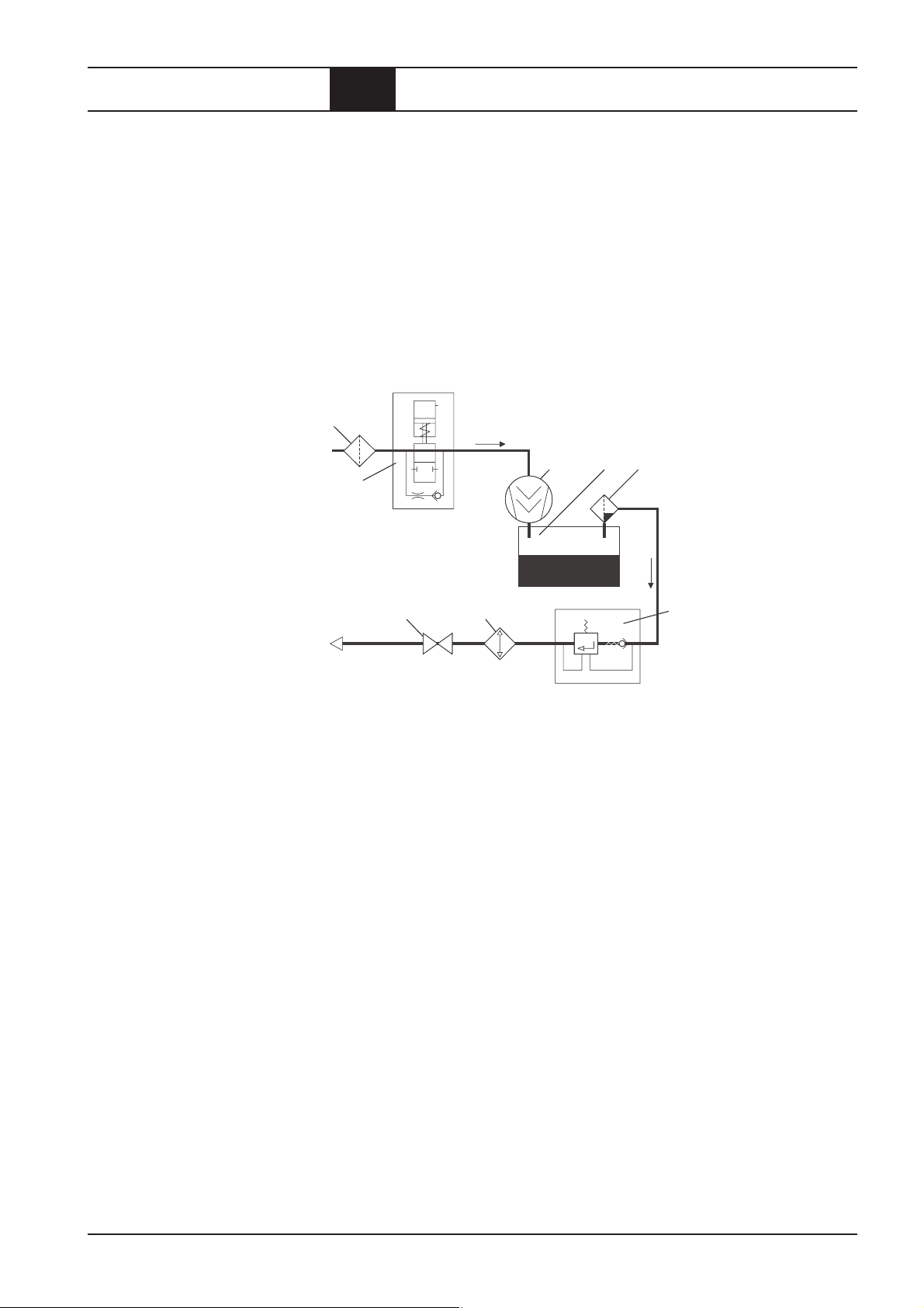
Luftkreislauf
Die Kompressorstufe arbeitet nach dem Verdrängerprinzip. In dem Gehäuse
drehen sich der über einen Elektromotor und Keilriemen angetriebene
Hauptläufer und der Nebenläufer.
Beide Läufer besitzen schraubenförmige Profile, die berührungsfrei ineinander greifen. Mit der Gehäusewandung bilden sie Kammern, die sich in
Durchflußrichtung der Luft ständig verkleinern.
Bei Drehung der Rotoren wird die angesaugte Luft in den Kammern bis auf
den Enddruck verdichtet.
Während der Verdichtung wird ständig Öl in die Kompressorstufe eingespritzt. Es dient zur Kühlung, Abdichtung und Schmierung.
1
543
2
Abb. 2.1:
Bauteile des
7 *8
6
Luftkreislaufs
* Option
1 = Ansaugfilter
Der Ansaugfilter reinigt die von der Kompressorstufe angesaugte Luft.
2 = Ansaugregler
Der Ansaugregler öffnet (Lastlauf) oder schließt (Leerlauf und Stillstand) die
Saugleitung abhängig vom Betriebszustand des Kompressors.
3 = Kompressorstufe
Die Kompressorstufe verdichtet die angesaugte Luft.
4 = Druckluft-Öl-Raum
Im Druckluft-Öl-Raum trennen sich Druckluft und Öl durch Schwerkraft voneinander.
5 = Ölabscheider
Der Ölabscheider scheidet das in der Druckluft enthaltene Restöl ab.
6 = Mindestdruck-Rückschlagventil
Das Mindestdruck-Rückschlagventil öffnet erst, wenn der Systemdruck auf
3,5 bar angestiegen ist. Dies bewirkt einen schnellen Aufbau des Systemdrucks und stellt die Schmierung in der Anlaufphase sicher. Nach dem Ausschalten des Kompressors verhindert das Rückschlagventil, daß die Druckluft aus dem Netz zurückströmt.
7* = Druckluft-Nachkühler (luftgekühlt)
Im Druckluft-Nachkühler wird die verdichtete Luft abgekühlt. Dabei kondensiert das in der Luft enthaltene Wasser aus.
8 = Absperrventil
Über das Absperrventil kann der Schraubenkompressor vom Netz getrennt
werden.
BOGE Betriebsanleitung für Schraubenkompressor-Modul Baureihe CM 9
Produkt.pm6.5 - D
Seite 2.3
Page 17
Produktbeschreibung
2.2 Funktionsbeschreibung
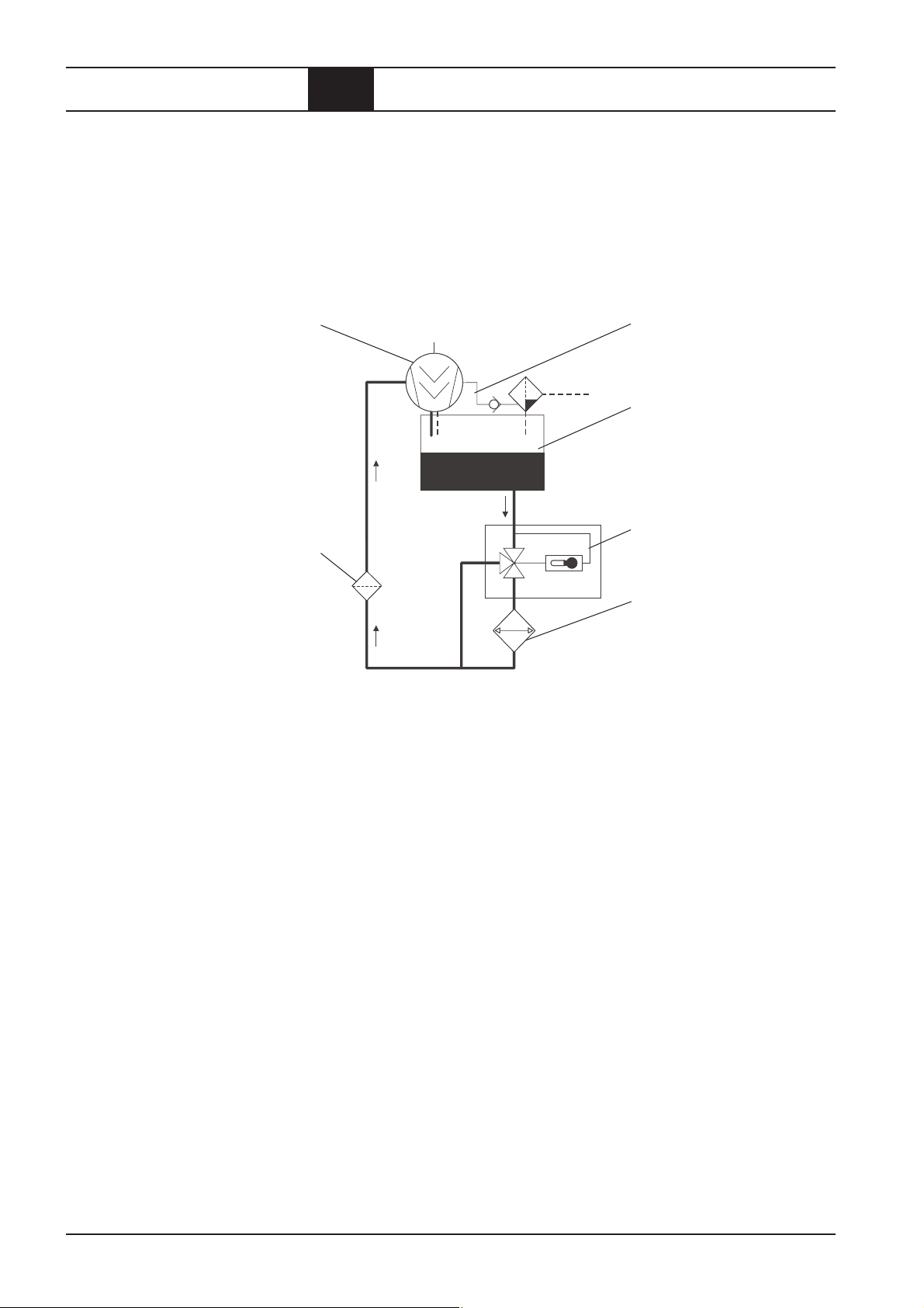
Ölkreislauf
Das in die Kompressorstufe eingespritzte Öl hat folgende Aufgaben:
– Abführen der Kompressionswärme (Kühlung)
– Abdichtung der Spalte zwischen den Läufern sowie zwischen Läufern
und Gehäuse
– Schmierung der Lager
56
1
2
4
3 *
Abb. 2.2: Bauteile
des Ölkreislaufs
* bauseits
1 = Druckluft-Öl-Raum
Im Druckluft-Öl-Raum sammelt sich das aus der Druckluft durch
Schwerkraft abgeschiedene Öl.
Der Systemdruck drückt dieses aus dem Raum in die Kompressorstufe.
2 = Thermostatisches Ölregelventil
Das thermostatische Ölregelventil lenkt das Öl abhängig von dessen
Temperatur entweder durch den Ölkühler oder durch einen Bypass
(z.B. in der Anlaufphase).
Das Öl hält so stets seine optimale Betriebstemperatur.
3* = Ölkühler (luft- oder wassergekühlt) bauseits (vom Anwender beizustellen und auszulegen).
Der Ölkühler kühlt das heiße Öl auf Betriebstemperatur ab.
4 = Ölfilter
Der Ölfilter hält Verunreinigungen im Öl zurück.
5 = Kompressorstufe
Das eingespritzte Öl gelangt mit der Druckluft zurück in den Druckluft-ÖlRaum. Dort wird es durch Schwerkraft abgeschieden.
6 = Drainageleitung
Über die Drainageleitung saugt die Kompressorstufe das Restöl, das sich
im Ölabscheider angesammelt hat, zurück in den Ölkreislauf
Seite 2.4
BOGE Betriebsanleitung für Schraubenkompressor-Modul Baureihe CM 9
Produkt.pm6.5 - D
Page 18

Produktbeschreibung
2.3 Regelung des Kompressors
Netzdruck
Betriebszustände
Beim Kompressor wird der Druck hinter dem Rückschlagventil als Netzdruck
bezeichnet. Die Steuerung schaltet den Kompressor während des Betriebs
abhängig vom Netzdruck ein und aus.
Alle Regelungen für Kompressoren bauen auf drei grundlegenden Betriebszuständen auf:
1. Lastlauf (Magnetventil mit Stern beaufschlagt / Antrieb läuft)
– Der Kompressor liefert sein Maximum an Druckluft.
– Er verbraucht dabei sein Maximum an Energie.
2. Leerlauf (Magnetventil stromlos / Antrieb läuft)
– Der Kompressor läuft, liefert aber keine Druckluft.
– Er verbraucht dabei ca. 75% weniger Energie als im Lastlauf.
– Bei Druckluftbedarf schaltet er ohne Verzögerung in den Lastlauf.
– Der Leerlauf reduziert die für den Antriebsmotor schädlichen Schalt-
häufigkeiten und mindert den Verschleiß der Anlage.
3. Stillstand in Betriebsbereitschaft (Magnetventil stromlos / Antrieb
steht still)
– Der Kompressor steht still, ist aber betriebsbereit.
– Bei Druckluftbedarf kann er ohne Verzögerung in den Lastlauf schalten.
Kurze
Betriebszeiten
ACHTUNG!
Bei kurzen Betriebszeiten erreicht der Kompressor nicht seine Betriebstemperatur. Er arbeitet unterhalb des Taupunktes. Das physikalisch bedingt
ausfallende Kondensat vermischt sich mit dem Öl. Die Schmierfähigkeit
des Öls läßt nach. Das führt zu Schäden an der Kompressorstufe.
Sprechen Sie bei kurzen Betriebszeiten unbedingt mit BOGE.
BOGE Betriebsanleitung für Schraubenkompressor-Modul Baureihe CM 9
Produkt.pm6.5 - D
Seite 2.5
Page 19

Produktbeschreibung
2.4 Regeleinrichtungen
Steuerung Betriebsdruckschalter
Optional: (auf Anfrage)
Vereinfachte Steuerung mit Kombistat zur Temperaturüberwachung und
Druckschalter zur Ansteuerung des Ansaugreglers
Seite 2.6
BOGE Betriebsanleitung für Schraubenkompressor-Modul Baureihe CM 9
Produkt.pm6.5 - D
Page 20
Produktbeschreibung
2.5 Sicherheits- u. Überwachungseinrichtungen
Allgemeines
SicherheitsTemperaturbegrenzung
Sicherheitsventil
Antrieb und Aufbau
ACHTUNG!
Der Betrieb des Kompressors ohne die eingebauten Sicherheitseinrichtungen
ist verboten. Die Sicherheitseinrichtungen dürfen nicht demontiert oder außer
Betrieb gesetzt werden.
Die Sicherheits-Temperaturbegrenzung (Pt 1000 Temperatursensor Serie)
muß vor der ersten Inbetriebnahme an die bauseitige Steuerung angeschlossen werden (hierzu siehe die Maßzeichnung auf Seite 2.8). Wenn die maximal
zulässige Verdichtungs-Endtemperatur erreicht wird, muß der Kompressor
abgeschaltet werden. Wird die Minimaltemperatur unterschritten, darf der Kompressor nicht eingeschaltet werden (Temperaturen siehe Seite 3.3).
Das Sicherheitsventil am Druckluft-ÖlRaum verhindert ein Überschreiten des
maximal zulässigen Drucks. Bei Überschreitung des Maximaldruckes (z.B. bei
1
Der CM 9 Schraubenverdichter kann sowohl mit E- als auch mit Verbrennungsmotor angetrieben werden. Die Drehrichtung der Antriebswelle ist durch einen
Pfeil gekennzeichnet. Ein Lauf in falscher Drehrichtung zerstört den Verdichter in wenigen Sekunden. Auf den Ungleichförmigkeitsgrad von Verbrennungsmotoren ist bei der Wahl der Antriebskupplung zu achten. Wir empfehlen die
Nachrechnung der torsionskritischen Drehzahl auch unter dem Aspekt, daß
ein Zylinder des Verbrennungsmotors aussetzt. Das SchraubenkompressorModul ist spannungsfrei (mechanisch) an den Antrieb und an die Druckleitung
über die in der Maßzeichnung für Verdichter angegebenen Anschlüsse anzuschließen. Die Druckluft tritt mit ca. 70 – 95°C am Block aus. Hier empfehlen
wir einen Druckluft-Nachkühler. Außerdem ist ein Ölkühler zu installieren.
Die abzuführende Wärmemenge beträgt etwa 80% der installierten Antriebsleistung.
Dieses Modul wurde auch für den Antrieb durch Keilriemen gebaut und verträgt somit auch eine größere Querkraft (also eine in radialer Richtung wirkende Kraft) am Antriebszapfen. Bei 20000 Stunden Soll-Lebensdauer (bei 4500
U/min mit 10% Ausfallwahrscheinlichkeit) der Wälzlager kann eine Querkraft
von maximal 1000 N am Zapfen angreifen. Bei einer Querkraft mit wechselnder Richtung, wie z.B. einer Unwucht, ist das Maximum 250 N. Der Angriffspunkt der Querkraft muss auf dem Antriebszapfen liegen. Falls eine Riemenscheibe auf einer Verlängerung des Antriebszapfens angebracht werden soll,
ist Rücksprache mit BOGE erforderlich. Axiale Kräfte auf den Antriebszapfen
sind zu vermeiden; nur Kräfte kleiner 20 N sind unbedenklich. Das Trägheitsmoment der Stufe beträgt etwa 0,0025 kgm². Ein auf den Zapfen übertragenes Drehmoment, das zwischen 0 und dem Doppelten des Nennmoments
schwankt, ist für die Stufe und die Paßfeder ungefährlich. Wenn der Antrieb
wie z.B. ein Verbrennungsmotor eine Ungleichförmigkeit erzeugt, die zu laufendem Wechsel der Drehmomentrichtung während jeder Umdrehung führt,
ist wegen der Belastung der Rotorzahnflanken und der Paßfeder Rücksprache
mit BOGE zu nehmen. Dabei ist auch der Fall zu betrachten, daß so ein Wechseldrehmoment nur während langer Leerlaufzeiten auftritt.
falscher Einstellung des Betriebsdruckschalters) bläst es die gesamte Liefermenge
des Kompressors ab.
BOGE Betriebsanleitung für Schraubenkompressor-Modul Baureihe CM 9
Produkt.pm6.5 - D
Seite 2.7
Page 21
Produktbeschreibung
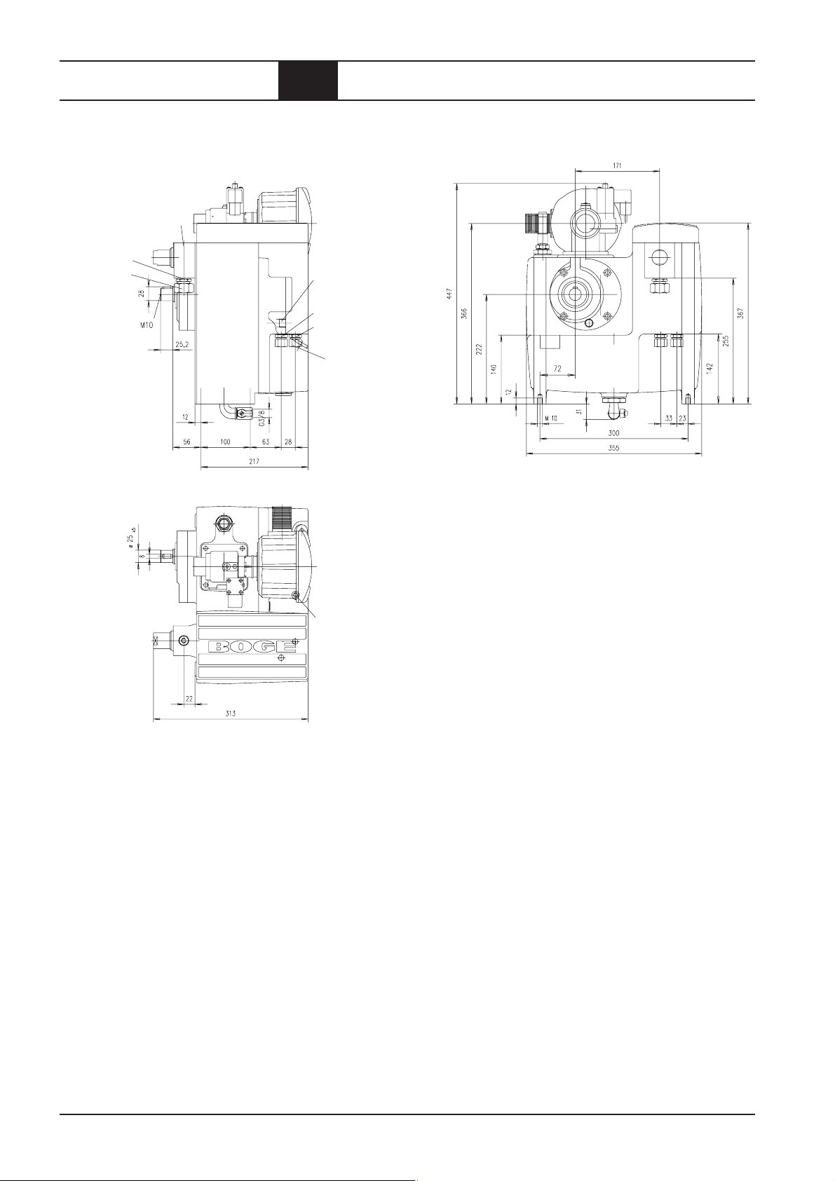
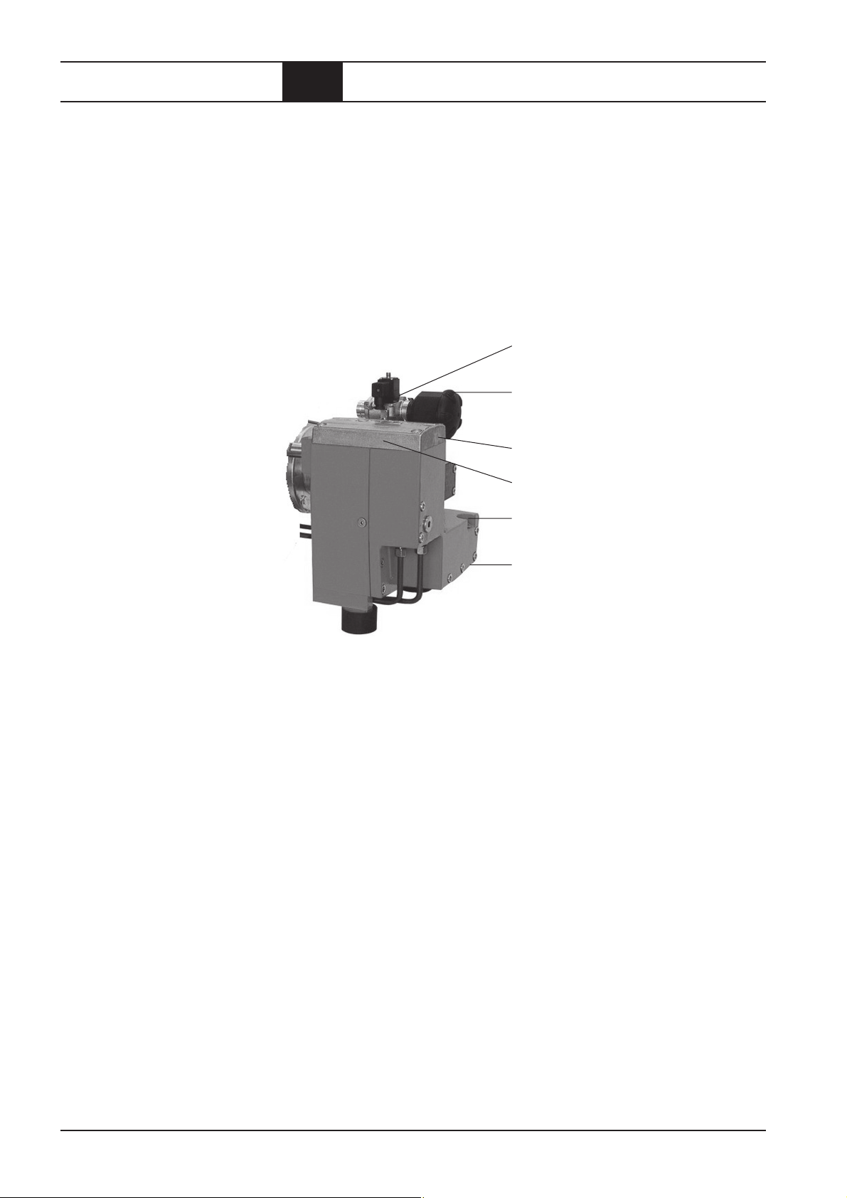
Netzdruck G1/8
Druckluft G1/2
Verschraubung
für Rohr AD 18
2.6 Abmessungen
Anschluß für
Temperatursensor G3/8
Öl zum Kühler G1/2
Öl vom Kühler G1/2
Verschraubung
für Rohr AD12
Systemdruck G1/8
Gewicht: 80 kg
Seite 2.8
BOGE Betriebsanleitung für Schraubenkompressor-Modul Baureihe CM 9
Produkt.pm6.5 - D
Page 22

Aufstellung
3.1 Transport
Allgemeines
Beachten Sie beim Transport des Kompressors die allgemein gültigen Sicherheits- und Unfallverhütungsvorschriften. BOGE haftet nicht für Schäden, die
durch unsachgemäßen Transport entstehen!
ACHTUNG!
Der Kompressor wird mit Ölfüllung ausgeliefert.
Er darf beim Transport nicht gekippt werden!
Das CM 9-Modul ist für den Betrieb in senkrechter Lage konstruiert, bei Abweichung der Aufstellebene (Füße des Moduls) in der Waagerechten von mehr
als 10° ist eine Rücksprache mit BOGE erforderlich.
BOGE Betriebsanleitung für Schraubenkompressor-Modul Baureihe CM 9
Aufstellung.pm6.5 - D
Seite 3.1
Page 23
Aufstellung
3.2 Der Betriebsraum
Aufstellungs-, Wartungsbedingungen und
Verwendungszweck für
untergebaute und
separat angeordnete
Druckluftbehälter
Brandschutz
– Druckluftbehälter müssen vor Beschädigungen durch mechanische Ein-
wirkungen (z.B. herabfallende Gegenstände) geschützt sein.
– Der Druckluftbehälter und seine Ausrüstung müssen von einem sicheren
Stand aus zu bedienen sein.
– Schutzbereiche und Schutzabstände sind einzuhalten.
– Der Druckluftbehälter muß sicher stehen. Er darf sich auch durch äußere
Kräfte nicht verlagern oder neigen. Das schließt auch das zusätzliche
Gewicht bei der Druckprüfung ein!
– Der Druckluftbehälter darf nicht mit dem Untergrund fest verschraubt sein.
– Der Druckluftbehälter muß von allen Seiten gut zugänglich sein (für wie-
derkehrende Prüfungen).
– Das Fabrikschild muß gut erkennbar sein.
– Druckluftbehälter müssen angemessen gegen Korrosion geschützt sein.
– Der Druckluftbehälter darf nur für Kompressoren mit Ein- und Ausschalt-
betrieb verwendet werden bei einem Druckschwankungsbereich Δ p ≤ 20 %
des maximalen Betriebsdrucks.
Für Räume, in denen Kompressoren mit Öleinspritzkühlung aufgestellt werden sollen, gelten folgende Vorschriften:
– Bei Kompressoren mit Motorleistungen über 40 kW muß der Betriebs-
raum besonders brandgeschützt sein.
– Kompressoren mit Motorleistungen über 100 kW müssen in separatem,
brandgeschütztem Raum aufgestellt werden.
Schallschutz
Anforderungen an brandgeschützte Betriebsräume:
– Wände, Decken, Fußböden und Türen müssen mindestens in der Feuer-
schutzklasse F30 ausgeführt sein.
– Im Betriebsraum dürfen keine brennbaren Flüssigkeiten gelagert werden.
– Der Fußboden um den Kompressor herum muß aus nicht brennbarem
Material bestehen.
– Auslaufendes Öl darf sich auf dem Fußboden nicht ausbreiten.
– Im Umkreis von mindestens drei Metern um den Kompressor dürfen sich
keine entzündlichen Stoffe befinden.
– Über dem Kompressor dürfen keine brennbaren Anlagenteile wie Kabel-
trassen verlaufen.
Kompressoren dürfen nur im Arbeitsbereich aufgestellt werden,
wenn ihr Meßflächen-Schalldruckpegel unter 85 dB (A) liegt.
Seite 3.2
BOGE Betriebsanleitung für Schraubenkompressor-Modul Baureihe CM 9
Aufstellung.pm6.5 - D
Page 24
Aufstellung
3.2 Der Betriebsraum
Zulässige
Umgebungseinflüsse
Der Betriebsraum muß sauber, trocken, staubfrei und kühl sein.
Zulässige Umgebungstemperaturen
Maximale Umgebungstemperatur (bei Luftkühlung): + 40°C
Minimale Umgebungstemperatur: + 5°C
ACHTUNG!
Die Nichteinhaltung der zulässigen Umgebungstemperaturen kann zu
folgenden Problemen führen:
– Bei zu hoher Temperatur schaltet der Kompressor ab (für Sicherheits-
abschaltungslogik hat der Kunde Sorge zu tragen). Bei Versagen
der Abschaltung über den Temperatursensor besteht Brandgefahr.
– Leitungen und Ventile frieren bei Unterschreitungen ein.
– Schäden durch reduzierte Schmierfähigkeit des Kompressorenöls.
Maßnahmen zum Einhalten der zulässigen Umgebungstemperaturen:
– Wärmeabstrahlende Leitungen und Aggregate in der Nähe des Kompres-
sors vermeiden oder gut isolieren.
– Kompressor nicht im Kühlluftstrom anderer Maschinen aufstellen.
– Zuluftöffnungen mit verstellbaren Jalousien versehen, damit die Minimal-
temperatur im Winter nicht unterschritten wird.
Be- und Entlüftung
Bei Nichtbeachtung der folgenden Hinweise kann die zulässige Verdichtungs-Endtemperatur überschritten werden.
Der Kompressor schaltet in diesem Fall selbsttätig ab.
ACHTUNG!
Die Ansaugöffnungen oder -kanäle des Kompressors sind so anzuordnen,
daß gefährliche Beimengungen (z.B. explosionsfähige oder chemisch instabile Stoffe) nicht angesaugt werden können.
Wenn Öl des CM 9-Moduls mit der Luft des Aufstellraumes gekühlt wird, ist
darauf zu achten, daß die Abwärme aus dem Aufstellraum abgeführt wird.
BOGE Betriebsanleitung für Schraubenkompressor-Modul Baureihe CM 9
Aufstellung.pm6.5 - D
Seite 3.3
Page 25
Aufstellung
3.2 Der Betriebsraum
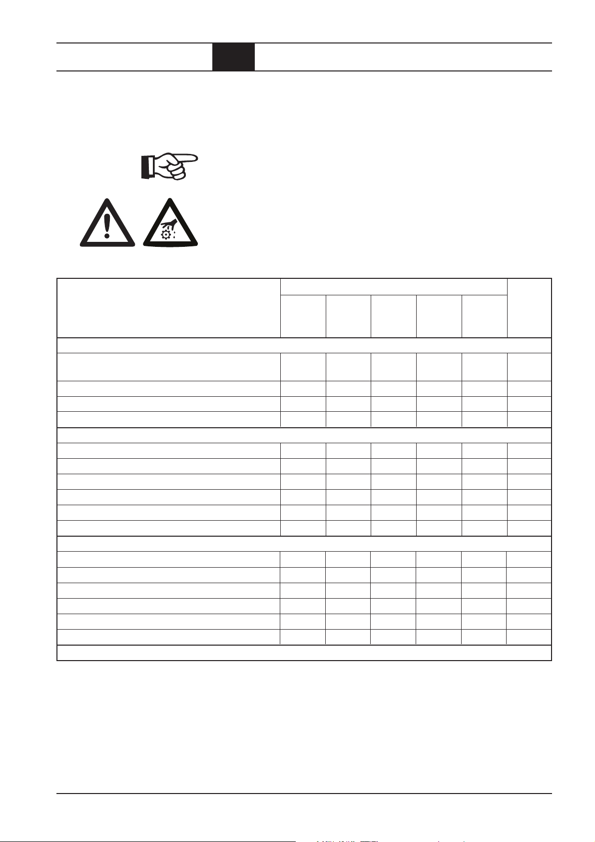
Kühlluftbedarf
(bei Luftkühlung)
Entsorgung des
anfallenden Kondensats
Aus der folgenden Tabelle können Sie den Kühlluftbedarf und die Größe der
Zuluftöffnungen für Ihren Kompressor entnehmen. Achten Sie darauf, daß
auch Klappen und Wetterschutzgitter über den notwendigen freien Querschnitt verfügen. Generell empfehlen wir Ihnen, sich für den Kanalbau und
die Auslegung an einen Kanalbauer zu wenden.
Typ Antriebs- * Kühlluftbedarf Erforderliche
leistung bei freier Zuluftöffnung
Aufstellung bei freier
Aufstellung
3
[kW] [m
CM 9 2,2 – 7,5 800 – 2800 0,10 – 0,35
/h] [m2]
Tabelle 1: Kühlluftbedarf, erforderliche Öffnungsquerschnitte.
* Für den Kühlluftbedarf wurde eine Temperaturdifferenz von 4°C zwischen Raum- und Außen-
temperatur zugrunde gelegt.
Die angesaugte Luft enthält Wasser in Form von Dampf, die in einem Nachkühler oder Druckluftbehälter als Kondensat ausfällt.
ACHTUNG!
Das anfallende Kondensat ist ölhaltig. Es darf ohne Aufbereitung nicht in
das öffentliche Kanalnetz eingeleitet werden.
Beachten Sie die Entwässerungsvorschriften Ihrer zuständigen Gemeinde.
Öl-Wasser-Trenner
Der BOGE-Öl-Wasser-Trenner (als Zubehör erhältlich) scheidet das Öl aus
dem Kondensat ab.
Das gereinigte Wasser kann in das öffentliche Abwassernetz eingeleitet
werden. Das Öl wird in einem eigenen Behälter aufgefangen. Es muß umweltgerecht entsorgt werden.
Wenn das Öl aufgrund besonderer Betriebsbedingungen emulgiert, muß
eine Emulsions-Spaltanlage eingesetzt werden.
Seite 3.4
BOGE Betriebsanleitung für Schraubenkompressor-Modul Baureihe CM 9
Aufstellung.pm6.5 - D
Page 26

Aufstellung
3.3 Montage
Allgemeines
Lieferumfang prüfen
ACHTUNG!
Alle Montagearbeiten dürfen nur von entsprechend unterwiesenen Personen
oder Fachkräften durchgeführt werden.
Jedes Modul CM 9 absolviert vor der Auslieferung im Werk einen Probelauf.
Er wird sorgfältig geprüft und eingestellt. Spätere Transportschäden können
jedoch nicht ausgeschlossen werden.
– Bitte kontrollieren Sie sofort nach der Lieferung den Kompressor und
reklamieren Sie Schäden beim letzten Transportführer – auch dann, wenn
die Verpackung nicht beschädigt ist! Zur Sicherung von Ansprüchen ge-
genüber dem Transportunternehmen empfehlen wir Ihnen, Maschinen,
Geräte und Verpackungsmaterialien vorläufig in dem Zustand zu belassen,
in dem Sie sie bei der Feststellung des Schadens vorgefunden haben.
– Untersuchen Sie den Kompressor vor der Inbetriebnahme auf äußere
Transportschäden.
– Beobachten Sie den Kompressor bei der Inbetriebnahme und dem folgen-
den Probelauf.
– Schalten Sie den Kompressor sofort aus, wenn Fehlfunktionen oder
Störungen auftreten. Informieren Sie in diesem Fall den BOGE-Service.
Der Lieferumfang ist abhängig von Ihrer Bestellung.
Bitte prüfen Sie vor der Inbetriebnahme ob alle benötigten Teile vorhanden
sind. Hinweise auf eventuelle Zusatzausstattungen entnehmen Sie bitte der
Auftragsbestätigung.
Ölstand prüfen
Im einzelnen umfaßt der Lieferumfang folgende Bauteile:
– Bedienungsanleitung
– Ölablaßschlauch
– Hutmutter.
BOGE-Kompressoren werden mit einer kompletten Ölfüllung ausgeliefert.
Prüfen Sie vor der Inbetriebnahme den Ölstand wie im Kapitel „Wartung“
beschrieben.
BOGE Betriebsanleitung für Schraubenkompressor-Modul Baureihe CM 9
Aufstellung.pm6.5 - D
Seite 3.5
Page 27
Aufstellung
3.4 Inbetriebnahme
Drehrichtung
prüfen
Dichtigkeit prüfen
Inbetriebnahme
nach längerem
Stillstand
ACHTUNG!
Prüfen Sie vor der ersten Inbetriebnahme unbedingt die Drehrichtung des
Antriebs. Auch kurzzeitiger Betrieb bei falscher Drehrichtung (mehr als 5 Sekunden) kann zur vollständigen Zerstörung der Kompressorstufe führen!
Die Drehrichtung muß mit dem Drehrichtungspfeil auf der Kompressorstufe
übereinstimmen.
– Zum Prüfen der Drehrichtung Kompressor ein- und sofort wieder aus-
schalten.
Um Undichtigkeiten und Leckagen vorzubeugen:
– Verschraubungen der Leitungen prüfen und falls erforderlich nachziehen.
Bei geplant längeren Stillstandzeiten sollten Sie den BOGE-Service zu Rate
ziehen.
Nach einem Stillstand von mehr als zwei Monaten muß vor dem Start des
Kompressors eine Teilmenge Öl in den Ansaugregler gefüllt werden.
ACHTUNG!
Verwenden Sie zum Auffüllen des Ansaugreglers ausschließlich Öl der Sorte,
mit dem der Kompressor betrieben wird.
Mischen Sie nie unterschiedliche Ölsorten und -fabrikate.
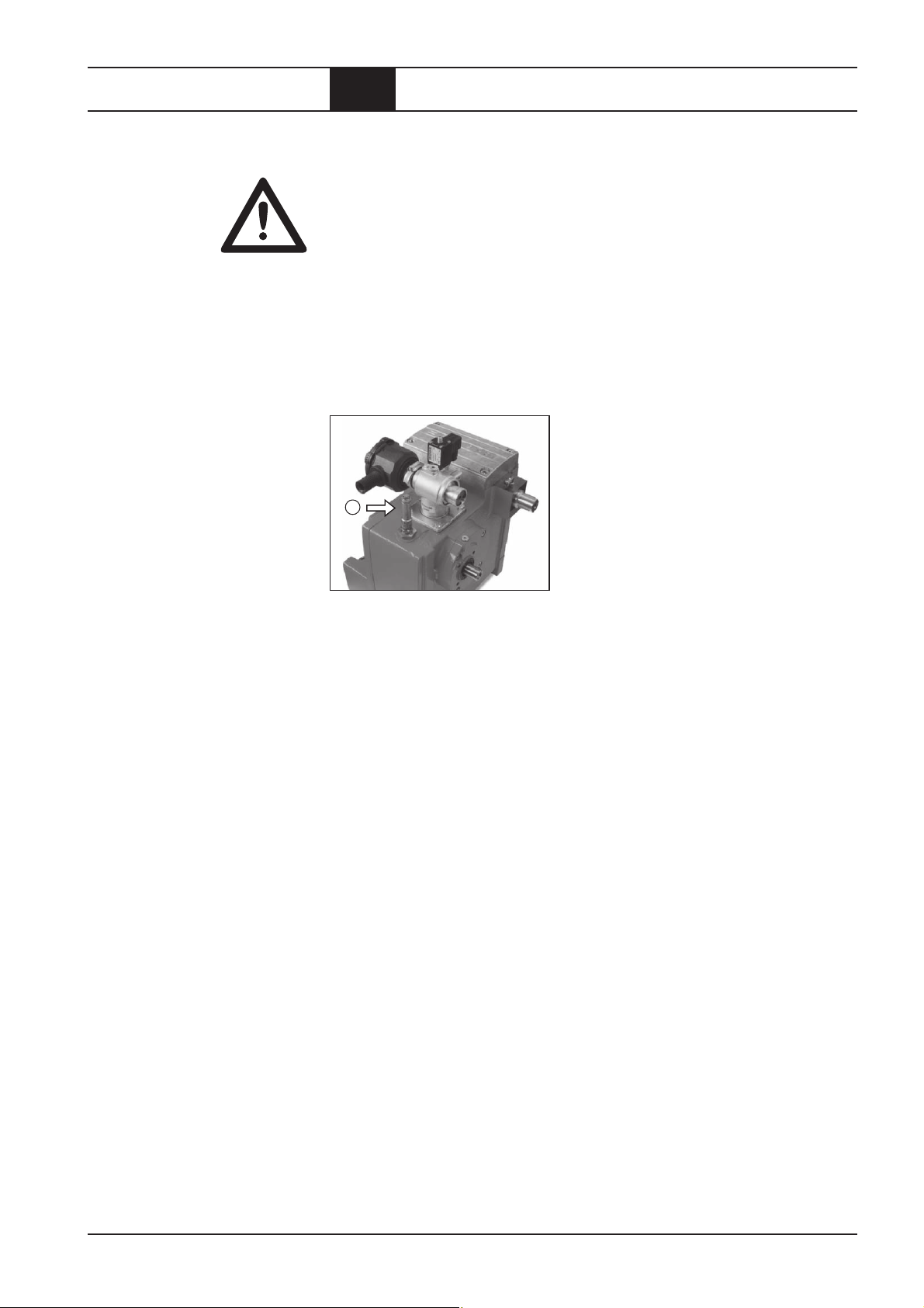
Vorsicht Verletzungsgefahr!
Hauptschalter ausschalten und gegen unbeabsichtigtes Wiedereinschalten
sichern.
– Stopfen auf dem Ansaugregler abschrauben.
– Ca.
– Stopfen wieder einschrauben.
– Kompressorstufe an der Welle von Hand 5- bis 10mal durchdrehen, damit
1
/4 Liter Kompressorenöl in den Ansaugregler einfüllen.
sich das Öl gleichmäßig verteilt.
1
Seite 3.6
Abb. 3.1: Ansaugregler
BOGE Betriebsanleitung für Schraubenkompressor-Modul Baureihe CM 9
Aufstellung.pm6.5 - D
Page 28
Wartung
4.1 Sicherheitshinweise
ACHTUNG!
Wartungsarbeiten dürfen nur von Fachkräften bzw. entsprechend unterwiesenen Personen durchgeführt werden.
– Bei Demontage von Sicherheitseinrichtungen für Wartungsarbeiten ist
der Kompressor, wie in dieser Betriebsanleitung beschrieben, außer Be-
trieb zu setzen. Unmittelbar nach Abschluß der Wartungsarbeiten sind
die Sicherheitseinrichtungen wieder zu montieren.
– Bei der Wartung dürfen nur die von BOGE zur Verwendung freigegebe-
nen Original-Ersatzteile, Kompressorenöle und Betriebsstoffe verwendet
werden.
– Bei Automatischem Wiederanlauf (Auto-Restart) kann der Kompressor
nach einem Spannungsausfall automatisch wieder anlaufen.
Voraussetzung: Der Netzdruck ist kleiner als der eingestellte Einschalt-
druck.
Vorsicht Verletzungsgefahr!
Beachten Sie bei allen Wartungsarbeiten stets die unten beschriebene
Arbeitsweise. Lassen Sie niemals einen Sicherheitsschritt aus!
Sie riskieren sonst Verletzungen durch Wiederanlauf, Stromschlag oder
selbstlösende Teile.
Vor allen Wartungsarbeiten:
1. Kompressor mit der AUS-Taste abschalten.
2. Hauptschalter ausschalten und gegen unbeabsichtigtes Wiedereinschalten sichern.
3. Prüfen, ob alle Anlagenteile wirklich elektrisch spannungsfrei sind.
4. Kompressor vom Druckluftnetz trennen.
Dazu z. B. Kugelhahn am Druckluftausgang schließen.
5. Kompressor entlüften.
Sicherheitsventil am kombinierten Druckluft-Öl-Behälter dazu wie
folgt lüften:
– Rändelmutter gegen den Uhrzeigersinn drehen, bis ein Feder-
widerstand spürbar wird.
– Rändelmutter geringfügig weiterdrehen.
Die eventuell vorhandene Restluft entweicht.
– Wenn die Restluft vollständig aus dem System entwichen ist,
Rändelmutter wieder festziehen.
Nach Abschluß der Wartungsarbeiten:
6. Kugelhahn am Druckluftausgang öffnen.
7. Vor dem Wiedereinschalten sicherstellen, daß kein Personal mehr
am Kompressor arbeitet.
BOGE Betriebsanleitung für Schraubenkompressor-Modul Baureihe CM 9
Wartung.pm6.5 - D
Seite 4.1
Page 29
Wartung
4.2 Allgemeines
Wartung durch den
BOGE-Service
Lassen Sie Ihren Kompressor nach jeweils 3000 Betriebsstunden oder jährlich vom BOGE-Service komplett prüfen.
Übersicht der regelmäßigen Wartungsarbeiten
Druck kontrollieren / einstellen
Druckschalter (bauseits)
Ölkühler reinigen
Ölkühler (bauseits)
Nach längerem Stillstand:
in den Ansaugregler Öl einfüllen
Ansaugfilter kontrollieren
– Filtereinsatz reinigen / wechseln
Ölfilter wechseln
Ölabscheider wechseln
Ölstand prüfen / Öl nachfüllen
Ölwechsel
Abb. 4.1: Übersicht der regelmäßigen Wartungsarbeiten.
Seite 4.2
BOGE Betriebsanleitung für Schraubenkompressor-Modul Baureihe CM 9
Wartung.pm6.5 - D
Page 30
Wartung
4.2 Allgemeines
Wartungsintervalle
Die in der Tabelle angegebenen Wartungsintervalle beziehen sich auf durchschnittliche Betriebs- und Umgebungsbedingungen.
Bei extremen Bedingungen können sich kürzere Wartungsintervalle ergeben.
Vermerken Sie jede durchgeführte Wartungsarbeit in der Tabelle auf
den letzten Seiten. Sie erleichtern damit dem BOGE-Service die Suche
nach Fehlerursachen.
Ölwechsel
Bei Einsatz eines Mineralöls oder eines lebensmitteltauglichen Öls sind nach
den ersten 500 Betriebsstunden Öl, Ölfilter und die Düse mit Schmutzfänger
zu wechseln.
Wartungsarbeit Wartungsintervall in Betriebsstunden
1)
Seite
wöchent-, 1.000 1.500 3.000 9.000
monat- jährlich jährlich jährlich alle
lich 2 Jahre
Allgemeine Wartungsarbeiten
Verdichtungs-Endtemperatur prüfen
(Sollwert: 70 – 100° C)
w–
Kompressor auf Undichtigkeiten prüfen X –
Funktion des NOT-AUS-Schalters prüfen m –
Öl-Kühler reinigen X 4.11
Luftkreislauf
Ansaugfilter prüfen bzw. reinigen m 4.6
Einsatz des Ansaugfilters wechseln X 4.6
Sicherheitsventil prüfen X 4.12
Mindestdruckventil (Verschleißteilsatz) austauschen X –
Ansaugregler (Verschleißteilsatz) austauschen X –
Magnetventil austauschen X–
Ölkreislauf
Ölstand prüfen und bei Bedarf Öl nachfüllen
Ölabscheider wechseln
Ölfilter wechseln
Öl wechseln
2)
2)
2)
2)
X 4.7
X4.9
X4.8
X4.9
Ölregler (Verschleißteilsatz) austauschen X –
Düse mit Schmutzfänger austauschen X –
Antrieb (bauseits)
1)
Wenn der Kompressor wenig benutzt wird, dann ist unabhängig von der Anzahl der Betriebsstunden die Wartung nach dem angegebenen
Intervall (wöchentlich/monatlich/jährlich) durchzuführen.
2)
Die angegebenen Intervalle gelten nur bei der Verwendung von BOGE-Kompressorenöl Syprem 8000 S! Je nach Umgebungstemperatur
sind andere Standzeiten durchaus möglich. Lassen Sie in diesem Fall das Öl durch Ihren BOGE-Service analysieren!
BOGE Betriebsanleitung für Schraubenkompressor-Modul Baureihe CM 9
Wartung.pm6.5 - D
Seite 4.3
Page 31

Wartung
4.2 Allgemeines
Allgemeine
Hinweise
zu den
verwendeten
Schmiermitteln
Vorsicht Verletzungsgefahr!
Bedingt durch ihre Inhaltsstoffe (Additive) sind Öle eine mögliche Gefahr
für Gesundheit und Umwelt.
– Vermeiden Sie Kontakt mit Haut und Augen.
Tragen Sie Schutzhandschuhe aus beständigem Kunststoff.
Waschen Sie sich nach Kontakt mit Ölen gründlich.
– Atmen Sie Dämpfe und Nebel nicht ein.
– Schützen Sie Ihre Umwelt.
Achten Sie darauf, kein Öl zu verschütten.
– Bei Umgang mit Ölen sind Feuer, offenes Licht und Rauchen streng-
stens verboten.
Wir empfehlen Öle nach folgender Schmierölanforderung:
– Viskositätslage von 55 mm²/s bei 40°C
– Mindestviskosität bei 100°C von 8 mm²/s
– Höchstviskosität bei 0°C von 1.000 mm²/s
– FZG-Test nach DIN 51354 mit Schadenskraftstufe 10 erfüllen
– (FZG A/8,3/90 min 10)
– Alterungsbeständigkeit: Erfüllung der Anforderungen des Pneurop-
Oxidationstestes
– Zusätze zur Unterdrückung der Schaumbildung
– Zusätze zur Lösung von Ablagerungen
– Neutrales Verhalten gegenüber den verwendeten Dichtungsmaterialien
Neoprene, FPM, PTFE, FKM (Viton) und Anstriche auf Acryl- und Epoxid-
harzbasis
– Flammpunkt > 230°C
– Zusätze für ein gutes Wasserabscheidevermögen
– Zusätze für einen ausreichenden Korrosionsschutz metallischer Ober-
flächen
– Alterungsbeständigkeit: Nach Rotating Bomb Oxydation Test (ASTM D
2272) > 2.400 Minuten
– Erfüllung der Anforderungen der DIN 51 506 für VDL Schmieröle (bein-
haltet den Pneurop-Test)
– Oder Sie verwenden BOGE-Kompressorenöl
gebenen Wartungsintervalle beziehen sich nur auf
–
Syprem 8000 S
– Mischen Sie niemals unterschiedliche Ölsorten und -fabrikate miteinander.
Unter Umständen vertragen sich die Zusätze nicht. Es kann zu Schaum-
bildung, vorzeitiger Alterung oder einer Verringerung der Schmierfähigkeit
kommen.
kann von den BOGE-Verkaufsstellen bezogen werden.
Syprem 8000 S.
Syprem 8000 S
Die ange-
Seite 4.4
BOGE Betriebsanleitung für Schraubenkompressor-Modul Baureihe CM 9
Wartung.pm6.5 - D
Page 32

Wartung
4.2 Allgemeines
Entsorgung
verbrauchter
Betriebsstoffe
Ersatz- und
Verschleißteile
ACHTUNG!
Die Handhabung und Entsorgung von Mineralölen unterliegt gesetzlichen
Bestimmungen. Sie machen sich strafbar, wenn Sie Altöl nicht fachgerecht
entsorgen!
Beauftragen Sie mit der Entsorgung der verbrauchten Betriebsstoffe eines
der bekannten Dienstleistungsunternehmen, oder liefern Sie sie an eine
autorisierte Annahmestelle ab.
Beachten Sie bei der Entsorgung des Altöls folgende Punkte:
– Vermischen Sie das anfallende Altöl nicht mit anderen Stoffen oder
Flüssigkeiten.
– Verbrauchte Ölfilter und Ölabscheiderpatronen gehören in den Sonder-
müll und nicht in den normalen Abfall!
ACHTUNG!
Bei Reparatur oder Wartung dürfen nur die von BOGE zur Verwendung
freigegebenen Original-Ersatzteile, Kompressorenöle und Betriebsstoffe
verwendet werden.
BOGE haftet nicht für Schäden, die durch die Verwendung anderer
Ersatzteile und Betriebsstoffe entstehen.
ACHTUNG!
Bei verschmutzter Düse mit Schmutzfänger kann der Ölverbrauch sehr stark
zunehmen!
BOGE Betriebsanleitung für Schraubenkompressor-Modul Baureihe CM 9
Wartung.pm6.5 - D
Seite 4.5
Page 33

Wartung
4.3 Regelmäßige Wartungsarbeiten
Ansaugfilter reinigen
bzw. wechseln
Filtereinsatz reinigen
Reinigung: – 1x monatlich,
mindestens jedoch alle 500 Betriebsstunden.
– Bei starker Verschmutzung der angesaugten Luft
entsprechend früher.
Wechsel: – Bei Beschädigungen.
– Nach zweimaliger Reinigung.
– Kompressor mit der AUS-Taste abschalten.
Vorsicht Verletzungsgefahr!
Hauptschalter ausschalten und gegen unbeabsichtigtes Wiedereinschalten
sichern.
Filtereinsatz entnehmen
– Deckel des Filtergehäuses abnehmen (s. Abb. 4.2).
– Filtereinsatz herausnehmen (s. Abb. 4.2).
ACHTUNG! Filtereinsatz nicht in Flüssigkeiten reinigen.
Zum Reinigen keine harten Gegenstände verwenden, damit das Filterpapier
nicht beschädigt wird.
Bei Beschädigungen oder nach zweimaliger Reinigung muß der Einsatz
gegen einen neuen Filtereinsatz ausgetauscht werden.
– Filtereinsatz mit der Handfläche ausklopfen, damit der grobe Staub aus-
fällt.
– Feinen Staub mit trockener Druckluft (Maximaldruck 5 bar) von innen
nach außen ausblasen.
– Dichtfläche des Filtereinsatzes reinigen.
Filtereinsatz einsetzen
– Filtereinsatz in Filtergehäuse einsetzen.
– Deckel des Filtergehäuses anbringen.
1
2
Abb. 4.2: Ansaugfilter wechseln
Seite 4.6
BOGE Betriebsanleitung für Schraubenkompressor-Modul Baureihe CM 9
Wartung.pm6.5 - D
Page 34

Wartung
4.3 Regelmäßige Wartungsarbeiten
Ölstand kontrollieren,
Öl nachfüllen
Kontrolle: – Vor der ersten Inbetriebnahme des Kompressors.
– Danach alle 1.000 Betriebsstunden,
jedoch mindestens 1x jährlich.
Nachfüllen: – Wenn der Ölstand unter die Marke „min“ abgesunken ist
(siehe Skizze).
ACHTUNG!
Verwenden Sie zum Nachfüllen stets die gleiche Ölsorte.
Mischen Sie nie unterschiedliche Ölsorten und -fabrikate miteinander.
– Kompressor mit der AUS-Taste abschalten.
Vorsicht Verletzungsgefahr!
Hauptschalter ausschalten und gegen unbeabsichtigtes Wiedereinschalten
sichern.
– z. B. Kugelhahn am Druckluftausgang schließen.
– Kompressor entlüften (wie am Anfang des Kapitels beschrieben).
– Ca. 3 Minuten warten, bis sich das Öl gesetzt hat.
Vorsicht Verletzungsgefahr!
Verbrühungsgefahr durch heißes Öl!
– Stopfen des Öleinfüllstutzens herausdrehen.
– Ölstand prüfen.
Der Ölstand darf nicht unter die Marke „min“ absinken (siehe Skizze).
– Falls erforderlich, Öl bis zum unteren Gewinderand (Marke „max.“) des
Öleinfüllstutzens nachfüllen.
– Stopfen wieder einschrauben.
– Kugelhahn am Druckluftausgang öffnen.
Abb. 4.3: Ölstand prüfen, Öl nachfüllen
BOGE Betriebsanleitung für Schraubenkompressor-Modul Baureihe CM 9
Wartung.pm6.5 - D
2
1
Seite 4.7
Page 35

Wartung
4.3 Regelmäßige Wartungsarbeiten
Ölfilter wechseln
(Abb. 4.4)
Wechsel: – Nach den ersten 500 Betriebsstunden.
– Nach 3.000 Betriebsstunden,
spätestens jedoch nach einem Jahr.
– Bei jedem Ölwechsel!
– Kompressor mit der AUS-Taste abschalten.
Vorsicht Verletzungsgefahr!
Hauptschalter ausschalten und gegen unbeabsichtigtes Wiedereinschalten
sichern.
– z. B. Kugelhahn am Druckluftausgang schließen.
– Kompressor entlüften (wie am Anfang des Kapitels beschrieben).
– Ca. 3 Minuten warten, bis sich das Öl gesetzt hat.
Vorsicht Verletzungsgefahr!
Heiße Oberflächen nicht berühren!
– Schrauben am Wartungsdeckel lösen und Deckel abnehmen.
– Ölfilterpatrone herausziehen und vom Stützkörper abziehen.
– Stützkörper in die neue Ölfilterpatrone schieben.
ACHTUNG!
Überström / Rückschlagventil muß nach oben montiert sein.
– Ölfilterpatrone mit Stützkörper montieren.
– O-Ringe am Wartungsdeckel auf Beschädigungen prüfen und ggf. aus-
tauschen.
– Wartungsdeckel montieren und Schrauben anziehen.
– Kugelhahn am Druckluftausgang öffnen.
– Kompressor einschalten und bis auf Betriebstemperatur warmlaufen
lassen.
– Wartungsdeckel auf Dichtigkeit prüfen und Schrauben nachziehen.
Seite 4.8
3
Abb. 4.4: Ölfilter wechseln / Ölabscheider wechseln
BOGE Betriebsanleitung für Schraubenkompressor-Modul Baureihe CM 9
5
6
6
1
4
Wartung.pm6.5 - D
Page 36

Wartung
4.3 Regelmäßige Wartungsarbeiten
Ölabscheider wechseln
(Abb. 4.4)
Wechsel: – Nach 3.000 Betriebsstunden,
spätestens jedoch nach einem Jahr.
Wenn die vorgeschriebenen Wartungsintervalle nicht eingehalten
werden, können sich die Ölabscheider zusetzen. In diesem Fall steigt
der Differenzdruck so weit an, daß das Sicherheitsventil abbläst.
– Kompressor mit der AUS-Taste abschalten.
Vorsicht Verletzungsgefahr!
Hauptschalter ausschalten und gegen unbeabsichtigtes Wiedereinschalten
sichern.
– Heiße Oberflächen nicht berühren!
– Schrauben am Wartungsdeckel lösen und Deckel abnehmen.
– Ölabscheidepatrone nach oben aus der O-Ring-Abdichtung heraus-
ziehen.
– Sitz des O-Rings prüfen.
– Neue Ölabscheidepatrone im unteren Teil mit Öl benetzen und in die
O-Ring-Abdichtung drücken.
– O-Ringe am Wartungsdeckel auf Beschädigungen prüfen und ggf. aus-
tauschen.
– Wartungsdeckel montieren und Schrauben anziehen.
– Kugelhahn am Druckluftausgang öffnen.
– Kompressor einschalten und bis auf Betriebstemperatur warmlaufen las-
sen.
– Wartungsdeckel auf Dichtigkeit prüfen und Schrauben nachziehen.
Öl wechseln
Wechsel: – Nach 9.000 Betriebsstunden,
spätestens jedoch nach zwei Jahren.
– Bei anderen Ölsorten sind die entsprechenden Ölwechsel-
zeiten einzuhalten.
Unter folgenden Bedingungen verkürzen sich die Standzeiten des Öls, des
Ölfilters und der Ölabscheider:
– Bei Betrieb des Kompressors bei extremen Umgebungstemperaturen.
– Bei starker Verschmutzung der angesaugten Luft.
Druckpolster aufbauen
Der kombinierte Druckluft-Öl-Raum befindet sich an der tiefsten Stelle des
Systems. Zum Ablassen des Öls ist daher ein geringes Druckpolster (ca.
1,5 bar Systemdruck) erforderlich. Das Luftpolster drückt das Öl durch den
Ablaßschlauch in ein geeignetes Auffanggefäß (s. Abb. 4.6, 4.7).
BOGE Betriebsanleitung für Schraubenkompressor-Modul Baureihe CM 9
Wartung.pm6.5 - D
Seite 4.9
Page 37

Wartung
4.3 Regelmäßige Wartungsarbeiten
– Kompressor mit der AUS-Taste abschalten.
Vorsicht Verletzungsgefahr!
Hauptschalter ausschalten und gegen unbeabsichtigtes Wiedereinschalten
sichern.
Altes Öl ablassen
– Kompressor abschalten. Hutmutter nach ca. 2 sec. auf die Entlüftungs-
bohrung des Magnetventils schrauben.
Vorsicht Verletzungsgefahr!
– Verbrühungsgefahr durch heißes Öl!
– Blindstopfen bei geschlossenem Kugelhahn am Ölablaß entfernen.
– Ölablaßschlauch montieren (der Ölablaßschlauch befindet sich an der
Maschine).
– Ölablaßschlauch in ein geeignetes Gefäß verlegen.
– Kugelhahn langsam öffnen. Das Druckpolster drückt das Öl in das Gefäß.
– Wenn der Druckluft-Öl-Raum vollständig entleert ist, Kugelhahn schließen.
– Ölablaßschlauch entfernen und Blindstopfen mit neuer Kupferdichtung
wieder einschrauben.
– Hutmutter vom Magnetventil entfernen.
– Ölfilter wechseln (Vorgehensweise wie vor beschrieben).
– Ölabscheider wechseln (Vorgehensweise wie vor beschrieben).
Neues Öl auffüllen:
– Öl bis zum Gewinderand des Öleinfüllstutzens (max.) einfüllen
(Vorgehensweise wie vor beschrieben).
ACHTUNG!
Nach einem Ölwechsel muß vor dem Start des Kompressors eine Teil-
menge Öl in den Ansaugregler gefüllt werden.
Ölmenge und Vorgehensweise siehe Kapitel 3.5 „Inbetriebnahme nach längerem Stillstand“.
ACHTUNG!
Verwenden Sie zum Auffüllen nur die Ölsorte, die Sie vorher verwendet
haben. Mischen Sie nie unterschiedliche Ölsorten und -fabrikate miteinander.
Vor einem Wechsel der Ölsorte muß der Ölkreislauf gespült werden.
– Probelauf durchführen.
Vorsicht Verletzungsgefahr!
Gegen unbeabsichtigtes Wiedereinschalten sichern.
– Ölfilter und Ölabscheider auf Dichtigkeit prüfen und falls erforderlich von
Hand nachziehen (Vorgehensweise wie vor beschrieben).
– Ölstand kontrollieren (Vorgehensweise wie vor beschrieben).
Falls erforderlich, Ölverluste ergänzen.
Seite 4.10
BOGE Betriebsanleitung für Schraubenkompressor-Modul Baureihe CM 9
Wartung.pm6.5 - D
Page 38

Wartung
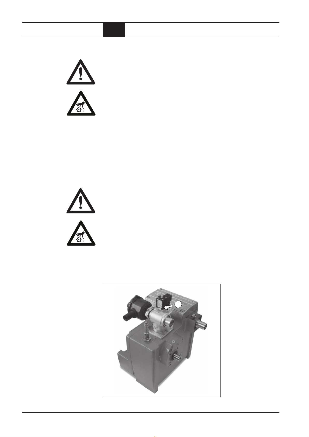
5
4.3 Regelmäßige Wartungsarbeiten
Abb. 4.5:
Magnetventil am Ansaugregler
mit aufgeschraubter Hutmutter
Ölkreislauf spülen
Druckluft-Öl-Kühler
reinigen (bauseits)
(nur bei
Luftkühlung)
3
Abb. 4.6:
Ölablaß Öl-Druckluft-Behälter
Das Spülen des Ölkreislaufs mit sauberem Öl ist erforderlich:
– Bei starker Verschmutzung des Öls.
– Vor einem Wechsel der Ölsorte.
ACHTUNG!
Genaue Informationen zum Spülen bei Einsatz von BOGE-Ölen erhalten Sie
unter der angegebenen Service-Nr.
Reinigung: – Nach 1.500 Betriebsstunden,
spätestens jedoch nach einem Jahr.
Die Standzeit des Druckluft-Öl-Kühlers hängt von der Verschmutzung
(Staub, Öldunst) der angesaugten Kühlluft ab. Starke äußere Verschmutzung des Kühlers führt zu überhöhter Temperatur im Ölkreislauf.
1
0 52 06 / 6 01-0
2
Abb. 4.7:
Ölablaß mit montiertem Ölablaßschlauch
– Kompressor mit der AUS-Taste abschalten.
Vorsicht Verletzungsgefahr!
Hauptschalter ausschalten und gegen unbeabsichtigtes Wiedereinschalten
sichern.
ACHTUNG!
Verwenden Sie zum Reinigen des Kühlers keine scharfen Gegenstände!
Sie könnten den Kühler beschädigen.
– Gelösten Schmutz mit Druckluft gegen die normale Strömungsrichtung
der Kühlluft ausblasen. Der ausgeblasene Schmutz kann mit einem
Industriestaubsauger direkt abgesaugt werden.
BOGE Betriebsanleitung für Schraubenkompressor-Modul Baureihe CM 9
Wartung.pm6.5 - D
Seite 4.11
Page 39

Wartung
4.3 Regelmäßige Wartungsarbeiten
Sicherheitsventil
prüfen
Kontrolle: – Nach ca. 3.000 Betriebsstunden,
jedoch mindestens 1x jährlich.
Sicherheitsventil durch Aufdrehen der Verschlußschraube prüfen.
Vorsicht Verletzungsgefahr!
– Verbrühung durch heißes Öl!
Sicherheitsventil bei laufendem Kompressor nur mit größter Vorsicht und
unter Beachtung aller Sicherheitsmaßnahmen prüfen.
Beim Aufdrehen entweicht ein heißes Luft-Öl-Gemisch!
– Verschlußschraube ‚ gegen den Uhrzeigersinn aufdrehen.
Das Luft-Öl-Gemisch entweicht.
– Verschlußschraube im Uhrzeigersinn festdrehen.
1
Abb. 4.8: Sicherheitsventil prüfen
Seite 4.12
BOGE Betriebsanleitung für Schraubenkompressor-Modul Baureihe CM 9
Wartung.pm6.5 - D
Page 40

Wartung
4.4 Ersatzteile und Zusatzausstattungen
Liste der Ersatzund Verschleißteile
(für Wartung)
Liste der erhältlichen
Zusatzausstattungen
Bezeichnung
Kompressorenöl Syprem 8000 S
Wartungspaket, bestehend aus:
Ölfilter, Ölabscheider, Ansaugfilterpatrone, Dichtungen,
Düse mit Schmutzfänger
Verschleißteilsätze für:
Ölregler, Mindestdruckventil, Magnetventil
Ansaugregler inkl. Magnetventil
Bezeichnung
Zusatzausstattungen zur Aufbereitung der Druckluft
Öl-Wasser-Trenner
Automatische Kondensatentleerung Bekomat
Druckschalter; Temperaturschalter (Kombistat)
Luftkühler für das Öl, Luftkühler als Druckluftnachkühler
Bitte geben Sie bei allen Bestellungen die Daten vom Typenschild an:
–Typ
– Baujahr
– Maschinennummer
BOGE Betriebsanleitung für Schraubenkompressor-Modul Baureihe CM 9
Wartung.pm6.5 - D
Seite 4.13
Page 41

Wartung
Seite 4.14
BOGE Betriebsanleitung für Schraubenkompressor-Modul Baureihe CM 9
Wartung.pm6.5 - D
Page 42

Anhang
Luftgekühlte Ausführung,
Standard
5.1 Fließschema
5
Luft EIN
28
4
1
18
9
M
7
8
11
15
12
10
14
27
16
17
Druckluft AUS
21
24
23
I
15
25
1 = Ansaugfilter
4 = Ansaugregler
5 = Entlüftungs- und Reglersteuerventil
7 = Antriebsmotor (bauseits)
8 = Kompressorstufe
9 = Verdichtungs-Endtemperatur-Anzeige und Schalter (bauseits)
10 = Kombinierter Druckluft-Öl-Raum
11 = Ölabscheider
12 = Sicherheitsventil
16 = Thermostatisches Ölregelventil
17 = Ölkühler (bauseits)
18 = Ölfilter
21 = Mindestdruck-Rückschlagventil
23 = Netzdrucktransmitter (bauseits)
24 = Manometeranzeige im Display (bauseits)
25 = Absperrventil Druckluft-Austritt (bauseits)
27 = Absperrventil Ölablaß
28 = Drossel mit Filter
BOGE Betriebsanleitung für Schraubenkompressor-Modul Baureihe CM 9
Fliess.pm6.5 - D
Seite 5.1
Page 43

Anhang
Druckluft-
Motor-
5.2 Liste der Wartungs- und Servicearbeiten
trockner
wartung
Kühler-
reinigung
Ölab-
scheider
**
Öl-
stand
Öl-
filter
*
filter
Ansaug-
ratur
Tempe-
druck
System-
Bitte vermerken Sie in den jeweiligen Spalten, welche Wartungsarbeiten Sie erledigt haben
Netz-
druck
W = Wechsel
** K = Kontrolle
Seite 5.2
stunden
Betriebs-
Datum Bemerkungen
W = Wechsel
* R = Reinigung
BOGE Betriebsanleitung für Schraubenkompressor-Modul Baureihe CM 9
Fliess.pm6.5 - D
Page 44

Anhang
Druckluft-
Motor-
5.2 Liste der Wartungs- und Servicearbeiten
trockner
wartung
Kühler-
reinigung
Ölab-
scheider
**
Öl-
stand
Öl-
filter
*
filter
Ansaug-
ratur
Tempe-
druck
System-
Bitte vermerken Sie in den jeweiligen Spalten, welche Wartungsarbeiten Sie erledigt haben
Netz-
druck
W = Wechsel
** K = Kontrolle
stunden
Betriebs-
Datum Bemerkungen
BOGE Betriebsanleitung für Schraubenkompressor-Modul Baureihe CM 9
Fliess.pm6.5 - D
W = Wechsel
* R = Reinigung
Seite 5.3
Page 45

Anhang
Druckluft-
Motor-
5.2 Liste der Wartungs- und Servicearbeiten
trockner
wartung
Kühler-
reinigung
Ölab-
scheider
**
Öl-
stand
Öl-
filter
*
filter
Ansaug-
ratur
Tempe-
druck
System-
Bitte vermerken Sie in den jeweiligen Spalten, welche Wartungsarbeiten Sie erledigt haben
Netz-
druck
W = Wechsel
** K = Kontrolle
Seite 5.4
stunden
Betriebs-
Datum Bemerkungen
W = Wechsel
* R = Reinigung
BOGE Betriebsanleitung für Schraubenkompressor-Modul Baureihe CM 9
Fliess.pm6.5 - D
Page 46

Operating
instructions
Screw compressor
module
Serie CM 9
Page 47

Index
Operating instructions
for screw compressors
module
– CM 9
BOGE KOMPRESSOREN
Postfach 10 07 13
D-33507 Bielefeld
Otto-Boge-Straße 1–7
D-33739 Bielefeld
Fon: ++49 / 52 06 / 6 01-0
Fax: ++49 / 52 06 / 6 01-200
Mail: info@boge.com
Net: www.boge.com
BOGE Operating instructions for CM 9 series screw compressor module
Inhalt.pm6.5 - GB
Issue: 07/2009
No. 596.0696.01
Nominal Price: € 5,00
Page I
Page 48

Index
Page II BOGE Operating instructions for CM 9 series screw compressor module
Inhalt.pm6.5 - GB
Page 49

Index
Index
Part 1:
General
Part 2:
Product description
1.1 General safety instructions .........................................................1.1
Safety instructions for compressor operation .................................1.1
Safety instructions for maintenance and repair of the compressor. 1.2
Accident prevention regulations ..................................................... 1.2
1.2 Introduction .................................................................................. 1.3
Symbols used................................................................................. 1.3
Symbols on the compressor ........................................................... 1.4
Intended use .................................................................................. 1.4
Inadmissible use ............................................................................1.4
Transport damage .......................................................................... 1.5
Data on the type plate ....................................................................1.5
Service ...........................................................................................1.5
2.1 Technical data ..............................................................................2.1
Technical data for CM 9 Compact module, part 1 ..........................2.1
Technical data for CM 9 Compact module, part 2 ..........................2.2
2.2 Function description .................................................................... 2.3
Function principle of the air end ..................................................... 2.3
Air circuit ........................................................................................ 2.3
Oil circuit ........................................................................................ 2.4
2.3 Compressor control .....................................................................2.5
Network pressure ...........................................................................2.5
Operating states ............................................................................. 2.5
Short operating times .....................................................................2.5
2.4 Control devices ............................................................................ 2.6
Operating pressure switch – Optional (on demand) .......................2.6
2.5 Safety and monitoring devices ................................................... 2.7
General .......................................................................................... 2.7
Safety temperature limiting device ................................................. 2.7
Safety valve ....................................................................................2.7
Compressor drive and design features........................................... 2.7
2.6 Dimensions ................................................................................... 2.8
Part 3:
Installation
BOGE Operating instructions for CM 9 series screw compressor module
Inhalt.pm6.5 - GB
3.1 Transport....................................................................................... 3.1
General .......................................................................................... 3.1
Page III
Page 50

Index
3.2 Compressor room ........................................................................ 3.2
Installation, maintenance conditions and application for
compressed air receivers arranged below or separately ................ 3.2
Fire protection ................................................................................ 3.2
Sound protection ............................................................................3.2
Admissible environmental influences ............................................. 3.3
Ventilation ....................................................................................... 3.3
Cooling air requirement (with air cooling) .......................................3.4
Condensate disposal ...................................................................... 3.4
3.3 Installation ....................................................................................3.5
General .......................................................................................... 3.5
Checking the delivery scope ..........................................................3.5
Checking the oil level ...................................................................... 3.5
3.5 Commissioning ............................................................................ 3.6
Checking the rotational direction ....................................................3.6
Checking for leaks.......................................................................... 3.6
Commissioning following extended stoppages ............................... 3.6
Part 4:
Maintenance
4.1 Safety instructions ....................................................................... 4.1
4.2 General .......................................................................................... 4.2
Maintenance through BOGE service .............................................. 4.2
Review of regular maintenance work ............................................. 4.2
Maintenance intervals .................................................................... 4.3
General information concerning the lubricants used ...................... 4.4
Disposal of used operating material ...............................................4.5
Spare and wearing parts ................................................................4.5
4.3 Regular maintenance work.......................................................... 4.6
Clean or change suction filter ......................................................... 4.6
Cleaning the filter cartridge ............................................................ 4.6
Checking the oil level, topping up oil .............................................. 4.7
Changing the oil filter .....................................................................4.8
Changing the oil separator .............................................................4.9
Oil change ......................................................................................4.9
Flushing the oil circuit ................................................................... 4.11
Cleaning the compressed air / oil cooling unit (on side)
(only with air cooling) ...................................................................4.11
Checking the safety valve ............................................................. 4.12
4.4 Spare parts and optional equipment ........................................ 4.13
List of spare and wearing parts (for maintenance) ....................... 4.13
List of available optional equipment .............................................4.13
Part 5:
Appendix
Page IV BOGE Operating instructions for CM 9 series screw compressor module
5.1 Flow chart ..................................................................................... 5.1
Air cooled version, standard ........................................................... 5.1
5.2 List of maintenance and service work........................................ 5.2
Inhalt.pm6.5 - GB
Page 51

General
1.1 General safety instructions
Nonobservance of the following safety instructions may lead to injuries
and damage to the compressor.
Also observe the generally valid safety and accident prevention regulations in addition to the information in these operating instructions!
Safety instructions for
compressor operation
1. Ensure that no commissioning and maintenance work on the compressor
is undertaken until these operating instructions are understood.
2. Only use the compressor for its intended use, as described in these
operating instructions.
3. The owner must ensure
– that only appropriately trained and authorized personnel work on this
compressor,
– that the operating, maintenance and repair personnel has been
made fully familiar with all safety instructions, and that they are being
observed,
– that the compressor is only operated in a safe operating condition.
4. Avoid any operating method which may impair the safety of the compressor.
5. Do not exceed the limit value for the final compression pressure specified
on the type plate.
6. Do not operate the compressor without the attendant protection and
safety devices.
Do not dismantle any built-in safety devices or put them out of operation.
Ensure that all safety claddings and doors are closed prior to commissioning/starting up the compressor and that they are not opened during
operation.
7. Place the compressor out of operation as described in these operating
instructions, when dismantling the safety claddings or safety devices for
repair or maintenance work. Reattach and close all cladding and safety
devices immediately upon completion of the repair or maintenance work.
8 Only operate the compressor using the additional equipment (options)
recommended or authorized by the manufacturer.
9. Undertake conversions and modifications of the compressor only in
agreement with BOGE, taking all relevant safety regulations into consideration.
The manufacturer is not liable for damages resulting from independent
modifications on the compressor.
10. Never start the compressor when one or serveral parts (e.g. cable, plug)
are damaged, when not in perfect working order and when damage is
detected or suspected.
11. Observe all safety and danger signs directly attached on the compressor!
12. The compressed air/oil receiver is subject to "Druckgeräterichtlinie"
(Recommendation for compressors) and has to be checked in prescribed
intervals.
BOGE Operating instructions for CM 9 series screw compressor module
Allgemeines.pm6.5 - GB
Page 1.1
Page 52

General
1.1 General safety instructions
Safety instructions for
maintenance and repair
of the compressor
1. Ensure that maintenance work is only carried out by appropriately trained
persons.
2. Ensure that setting work, malfunction rectification and repair is only carried
out by specialists or appropriately trained persons.
3. Prior to maintenance or repair work:
– Switch off the main switch.
– Secure main switch against unintentional switch-on.
– Check to ensure that all parts are currentless.
– Disconnect the compressor from the compressed air network (relieve
or block pressurized lines).
4. Exercise extreme caution during repair or maintenance work requiring
the compressor to be operational.
Ensure that persons keep out of reach of the hazardous area.
5. Ensure that work on the electrical equipment is only executed by qualified electricians.
6. Work on parts and devices under current is prohibited. Exceptions are
governed by the appropriate regulations, e.g. DIN VDE 0105.
7. Only use original spare parts, compressor oils and operating
materials released by BOGE during repair or maintenance.
8. The operator is responsible to check the compressor daily for externally
visible damage and defects, and to immediately report any changes
(including operational behaviour).
9. When the automatic restart (Auto-Restart) is activated, the compressor
will start automatically following a voltage loss.
Prerequisite: The net pressure is lower than the set switch-on pressure.
Accident prevention
regulations
The owner of a compressor plant is responsible to ensure that it is properly
installed, operated and maintained.
Prior to commissioning, owners in the Federal Republic of Germany urgently
have to read the currently valid regulations of the Main Association of the
Industrial Employers' Liability Insurance. Apart from other regulations particularly the Ordinance on Industrial Safety and Health (BetrSichV) is applicable.
The regulations are available at the following locations:
Berufsgenossenschaft (Industrial Employers' Liability Insurance)
Carl-Heymanns-Verlag KG, Luxemburger Straße 449, D-50939 Köln
Beuth Verlag GmbH, Burggrafenstraße 6, D-10787 Berlin
For operation of the compressor plant outside the Federal Republic of Germany, the accident prevention regulations of the country, where the compressor is operated, must be observed in addition to the data contained in
these operating instructions.
In the event that measures are required above and beyond the legal regulations specified in the Federal Republic of Germany or the data contained in
these operating instructions, then it is of utmost importance that these be
carried out prior to commissioning the compressor plant.
Page 1.2
BOGE Operating instructions for CM 9 series screw compressor module
Allgemeines.pm6.5 - GB
Page 53

General
1. 2 Introduction
The purpose of these operating instructions is to familiarize the user with the
function and all application possibilities of the compressor.
These operating instructions contain important information on how to operate
the compressor safely, economically and according to its intented use. Observing these operating instructions will assist in avoiding danger, to reduce
repair costs and down times and to increase the reliability and service life of
the compressor. It contains important information concerning the required
maintenance and repair measures, assists in case of malfunctions and contains data concerning spare and wearing parts.
The operating instructions must be available to the compressor operating
personnel at the place of operation, at all times.
The operating instructions must be carefully read and applied by all persons
engaged to undertake the following work on the compressor:
– Operation, including fault rectification and daily care
– Maintenance (service, inspection, repair)
– Commissioning
– Transport
Symbols used
The compressor and its additional equipment must not be installed and
commissioned until the operating instructions are understood.
These operating instructions can be supplemented with instructions on the
basis of existing national regulations concerning accident prevention and
environmental protection.
In the illustrations, the compressor is shown in part without safety cladding
or safety devices for better visualization. However, operation without these
components is prohibited!
In these operating instructions, important safety instructions and tips are
identified by the following symbols:
CAUTION: Risk of injury!
This symbol indicates information warning of possible danger to life and limb
of the operator or other persons.
ATTENTION!
This symbol indicates information warning of dangers to life and limb of the
operator or other persons or dangers, which might destroy or damage the
compressor.
WARNING: Voltage!
This symbol indicates information warning of life threatening electrical voltage levels.
It indicates work which must be exclusively performed by skilled electricians.
This symbol indicates information and tips concerning the economical and
careful operation of the compressor.
BOGE Operating instructions for CM 9 series screw compressor module
Allgemeines.pm6.5 - GB
Page 1.3
Page 54

General
1.2 Introduction
Symbols on the
compressor
Intended use
Inadmissible use
The following symbols and warning signs are fitted on the compressor:
Warning:
Hot surfaces: Do not touch.
Note:
Instructions for the operating personnel must be read.
The BOGE module CM 9 series C including its special accessories is designed for the compression of air only.
The air taken in must not contain any explosive or chemically instable gases
or vapours.
Do not exceed the specified final compression temperature.
The user has to provide suitable ambiance conditions. In cases of doubt a
consultion of BOGE service might be necessary (please avoid high ambient
temperatures, dirt and dripping water).
Never direct the produced compressed air towards persons.
Danger to life!
Oil is injected into the pressure rooms of the compressor.
Only use the produced compressed air for breathing or let it come in contact
with foods, if it was treated beforehand.
This BOGE screw compressor is not explosion protected.
Do not operate in explosive areas or in a possibly explosive atmosphere!
Do not operate the compressor in rooms in which extreme dust, toxic or
flammable vapours and gases may occur.
The following is not permitted:
– Exceeding the final compression pressure indicated on the type plate.
– Altering the safety devices and safety cladding or placing them out of
operation.
– Removing or painting over signs and symbols on the compressor.
– Operation of the compressor by unauthorized or untrained persons.
Page 1.4
BOGE Operating instructions for CM 9 series screw compressor module
Allgemeines.pm6.5 - GB
Page 55

General
1. 2 Introduction
Transport damage
Data
on the type plate
BOGE does not accept any liability for breakage or transport damage.
Please inspect the compressor immediately after delivery and direct damage
claims to the last haulier – even when the packing is not damaged!
To safeguard claims against the haulier we recommend leaving the machine,
devices and packing material in the same condition as they were in when
the damage was detected.
In the event of any other complaints, please inform us within six days after
arrival of the delivery.
Enter the data of your compressor from the type plate or enclosed data
sheet in the illustration below. This will ensure that in the event of enquiries,
you will always have the most important data to hand.
Type
Year of construction
Serial number
F. a . d . m3/min
Maximum service pressure bar
Motor speed min
–1
Motor power kW
Service
Otto-Boge-Straße 1– 7 · D-33739 Bielefeld · Telefon (0 52 06) 6 01-0
Postfach 100713 · D-33507 Bielefeld · Fax (0 5206) 601-2 00
www.boge.com · info@boge.com
Fig. 1.1: Data on the type plate
Please do not hesitate to contact BOGE service if you have any questions.
Please call:
++49-52 06 / 6 01-0
In the event of inquiries, always specify the following data of your compressor
to prevent any delays.:
– Type
– Year of manufacture
– Machine number
ATTENTION!
Only BOGE service technicians or persons authorized by BOGE in writing
may repair or alter the compressor during the warranty period. Otherwise all
warranty claims will expire!
BOGE Operating instructions for CM 9 series screw compressor module
Allgemeines.pm6.5 - GB
Page 1.5
Page 56

General
Page 1.6
BOGE Operating instructions for CM 9 series screw compressor module
Allgemeines.pm6.5 - GB
Page 57

Product description
2.1 Technical data
Technical data for CM 9 Compact module, part 1
Type CM 9
Dimensions
– Width [mm] 355
– Depth [mm] 315
– Height [mm] 450
Weight
– silenced [kg] 80
– super silenced [kg] –
Max. sound pressure level [±3 dB(A)]
accord. to DIN 45635, part 13
– silenced / super silenced [dB(A)] 61 – 68
Measuring surface dimension
– silenced / super silenced [dB(A)] 13
Sound capacity level
– silenced / super silenced [dB(A)] 74 – 81
Compressor
max. final compression temperature [°C] 110
Volume flow according to
ISO 1217 appendix C at:
– p
= 8 bar [m3/min] –
max
= 10 bar [m3/min] 0,340 – 1,100
– p
max
– p
= 13 bar [m3/min] –
max
Drive
Rated power [kW] 2,2 – 7,5
Nominal speed [min-1] 1100 – 4860
BOGE Operating instructions for CM 9 series screw compressor module
Produkt.pm6.5 - GB
Page 2.1
Page 58

Product description
2.1 Technical data
Technical data for CM 9 Compact module, part 2
Type CM 9
Oil filling quantity
Total oil filling quantity [l] 4
Oil topping up quantity
between min. + max. [l] 1
Intake air temperature
– min. [°C] 5
– max. [°C] 40
Cooling air requirement
3
– free-standing installation [m
/h] 800 – 2000
– with supply and exhaust [m3/h] –
– free ventilator pressure [Pa] –
– free ventilator pressure [mm water col.] –
Safety valve
Activation pressure at:
= 13 bar [bar] 14
– p
max
Page 2.2
BOGE Operating instructions for CM 9 series screw compressor module
Produkt.pm6.5 - GB
Page 59

Product description
2.2 Function description
Function principle
of the air end
Air circuit
The air end operates according to the displacement principle. In the housing,
the main and secondary screws are driven by means of an electric motor and
V-belt.
Both screws have screw-shaped profiles, intermeshing without contact.
Together with the housing wall, these screws form chambers which gradually
reduce in size, seen in air flow direction.
Rotation of the rotors causes the air taken in to be compressed to the final
pressure in the chambers.
During compression oil is continuously injected into the air end. This having
a cooling, sealing and lubricating function.
1
543
2
Fig. 2.1:
Components
8
7 *
6
of the air circuit
* Option
1 = Intake filter
The intake filter cleans the air suctioned by the air end.
2 = Intake regulator
The intake regulator opens (load operation) or closes (idling operation or standstill) the suction line depending on the operating condition of the compressor.
3 = Air end
The air end compresses the suctioned air.
4 = Compressed air/oil receiver
The compressed air separates from the oil under the force of gravity in the
compressed air/oil receiver.
5 = Oil separator
The oil separator separates the residual oil contained in the compressed air.
6 = Minimum pressure check valve
The minimum pressure check valve does not open until the system pressure
has increased to 3.5 bar. This causes a rapid build-up of the system pressure
and ensures lubrication in the starting phase. Once the compressor has been
switched off, the check valve prevents the compressed air from flowing back
out of the mains line.
7* = Compressed air after-cooler (air cooled)
The compressed air is cooled in the compressed air after-cooler, causing the
water contained in the air to condensate.
8 = Stop valve
The screw compressor may be isolated from the mains by means of the stop
valve.
BOGE Operating instructions for CM 9 series screw compressor module
Produkt.pm6.5 - GB
Page 2.3
Page 60

Product description
2.2 Function description
Oil circuit
The oil injected into the air end has the following function:
– It dissipates the compression heat (cooling)
– It seals the gaps between the screws and between the screws and housing
– It lubricates the bearings
56
1
2
4
3 *
Fig. 2.2:
Components
of the oil circuit
* on site
1 = Compressed air/oil receiver
The oil separated from the compressed air through the force of gravity collects
in the compressed air/oil receiver.
The system pressure forces it out of the receiver into the air end.
2 = Thermostatic oil control valve
Depending on the oil temperature, the thermostatic oil control valve either
allows the oil to pass through the oil cooler or through a bypass (e.g. in the
starting phase).
Thus the oil constantly maintains its optimum operating temperature.
3* = Oil cooler (air or water cooled, on site) to be provided by customer.
The oil cooler cools down the hot oil to operating temperature.
4 = Oil filter
The oil filter traps impurities in the oil.
5 = Air end
The injected oil returns to the compressed air/oil receiver together with the
compressed air. There, it is separated through the force of gravity.
6 = Drainage line
The air end suctions the residual oil which collects in the oil separator back
into the oil circuit via a drainage line.
Page 2.4
BOGE Operating instructions for CM 9 series screw compressor module
Produkt.pm6.5 - GB
Page 61

Product description
2.3 Compressor control
Network pressure
Operating states
For the compressor, the pressure downstream of the check valve is termed
network pressure. The control system switches the compressor on and off
during operation depending on the network pressure.
All screw compressor controls are based on three basic operating states:
1. Load operation (energized solenoid valve/motor is on)
– The compressor delivers its maximum amount of compressed air.
– It consumes its maximum energy.
2. Idling operation (de-energized solenoid valve/motor is on)
– The compressor runs but does not deliver any compressed air.
– It consumes approx. 75% less energy than in load operation.
– When compressed air is required, it switches to load operation with-
out delay.
– Idling operation reduces switching frequencies which can damage the
drive motor, and reduces wear of the system.
3. Standstill ready for operation (de-energized solenoid valve/motor in
standstill)
– The compressor is standing still but ready for operation.
– When compressed air is required, it switches automatically to load
operation.
Short operating
times
ATTENTION!
During short operating times, the compressor does not reach its operating
temperature. It operates below the dew point. The generated condensate
mixes with the oil. The lubricating ability of the oil is reduced. This leads to
damage on the air end.
It is of utmost importance to consult BOGE, if you operate your system with
short operating times.
BOGE Operating instructions for CM 9 series screw compressor module
Produkt.pm6.5 - GB
Page 2.5
Page 62

Product description
2.4 Control devices
Operating pressure
switch
Optional: (on demand)
Easier control with Kombistat for monitoring the temperature and pressure
switch for controlling the intake regulator.
Page 2.6
BOGE Operating instructions for CM 9 series screw compressor module
Produkt.pm6.5 - GB
Page 63

Product description
2.5 Safety and monitoring devices
General
Safety temperature
limiting device
Safety valve
ATTENTION!
Do not operate the compressor without built-in safety devices.
Do not dismantle the safety devices or put them out of operation.
The safety temperature limiting device (Pt 1000 Temperature sensor series)
has to be connected to the control on site prior to commissioning. (see also
dimensioned drawing on page 2.8) Once the maximum admissible final
compression temperature has been reched, the compressor has to switched
off. The compressor must not switch on when dropping below the minimum
temperature. (Temperatures see page 3.3).
Safety valve on the compressed air/oil
receiver prevents the maximum admissible pressure being exceeded. When
the maximum pressure is exceeded (e.g.
1
incorrect setting of the operating pressure
switch), the entire delivery volume of the
compressor is ejected.
Compressor drive
and design features
The CM 9 screw compressor qualifies for both electric motor or I.C. engine
drive. An arrow is used to indicate the sense of rotation of the driving shaft.
Wrong sense of direction will cause the compressor to be destroyed within
seconds. Proper clutch selection largely depends on the degree of irregularity of I.C. engines. It is therefore recommended to check the critical torsion
speed with regard to likely I.C. engine cylinder misfire. Use connections as
shown in compressor outline drawing to connect screw compressor module
free of (mechanical) tension to drive system and compressed air line. Compressed air protrudes from block at approx. 70 – 95°C. Apart from a compressed air after-cooler, an oil cooler should also be provided. The amount
of waste heat is estimated at around 80% of the installed drive power.
Present module is also suited for V-belt drive and larger transverse forces
(thus acting in radial direction) impacting on the driving journal. Taking into
account the roller bearings and their rated working life of 20,000 hours (at
4,500 rpm including a 10% failure risk), a max. transverse force of 1,000 N is
admissible to act on the driving journal, whereas in the event of transverse
forces acting in alternating directions (as may occur in case of an unbalance)
max. forces should not exceed 250 N. Transverse forces must at any rate
impact on the driving journal. Please contact BOGE if a belt pulley is to be
mounted on the driving journal’s extension. Make sure that no axial forces can
act on the driving journal; forces of less than 20 N are negligible. The moment
of inertia of this stage is around 0,0025 kg/m². Torsional moments ranging
from 0 and twice the rated moment and acting on the drive journal will cause
no harm to neither stage nor adjusting spring. If, for example, unbalance is
generated by an I.C. engine causing the torque direction to change during
rotation, please contact BOGE with view to the loads acting on both rotor
teeth surfaces and adjusting spring. It should also be taken into account that
such type of changing torques will only occur during prolonged idle times.
BOGE Operating instructions for CM 9 series screw compressor module
Produkt.pm6.5 - GB
Page 2.7
Page 64

Product description
Line pressure G1/8
2.6 Dimensions
Compressed air
G1/2
Screw
connection for
pipe AD 18
Connection for
temperatur sensor G3/8
Oil to cooling unit G1/2
Oil from cooling unit G1/2
Screw connection
for pipe AD12
System pressure G1/8
Weight: 80 kg
Page 2.8
BOGE Operating instructions for CM 9 series screw compressor module
Produkt.pm6.5 - GB
Page 65

Installation
3.1 Transport
General
Please observe the generally accepted safety and accident prevention regulations when transporting the compressor. BOGE accepts no liability for
damage caused by improper transport!!
ATTENTION!
The compressor is delivered filled with oil.
Do not tilt during transport!
The CM 9-Module is designed for an operation in vertical positon. If the
place of installation is inclined by more than 10% (feet of the module) it is
necessary to contact BOGE to coordinate the further proceeding.
BOGE Operating instructions for CM 9 series screw compressor module
Aufstellung.pm6.5 - GB
Page 3.1
Page 66

Installation
3.2 Compressor room
Installation,
maintenance conditions
and application for
compressed air
receivers arranged
below or separately
Fire protection
– Protect compressed air receivers against damage through mechanical
effects (e.g. falling objects).
– Operate the compressed air receiver and its equipment from a safe location.
– Adhere to safety areas and safety clearances.
– Ensure that the compressed air receiver stands securely. It must not shift
or tilt due to external forces. This also includes the additional weight dur-
ing a pressure test!
– The compressed air receiver must not be bolted to the base.
– Ensure that the compressed air receiver is easily accessible from all sides
(for recurring tests).
– Ensure that the factory label is clearly visible.
– Ensure that compressed air receivers are adequatly protected against
corrosion.
– Only use the compressed air receiver for compressors operating with cut-
in and cut-out mode if the pressure fluctuation range amounts to Δ p ≤ 20 %
of the maximum operating pressure.
The following applies to rooms in which compressors with oil injection cooling
are to be installed:
– For compressors with motor ratings exceeding 40 kW, ensure that the
compressor room is equipped with special fire protection.
– Install compressors with motor ratings exceeding 100 kW in a separate
fire protected room.
Sound protection
Requirements of fire protected compressor rooms:
– Walls, ceilings, floor and doors must be designed in fire protection class
F30 or higher.
– Flammable liquids must never be stored in the compressor room.
– The floor around the compressor must be made of non-flammable
material.
– Leaking oil must not spread out over the floor.
– No inflammable materials must be located within a radius of at least
3 metres around the compressor.
– No inflammable machine parts, such as cable ducts, may run overhead
of the compressor.
Only install compressors in workrooms if the sound pressure level of
their measuring surfaces does not exceed 85 dB(A).
Page 3.2
BOGE Operating instructions for CM 9 series screw compressor module
Aufstellung.pm6.5 - GB
Page 67

Installation
3.2 Compressor room
Admissible
environmental
influences
The compressor room must be clean, dry, cool and free of dust.
Admissible ambient temperatures
Maximum ambient temperature (for air cooling): + 40°C
Minimum ambient temperature: + 5°C
ATTENTION!
Nonobservance of the admissible ambient temperature may lead to the
following problems:
– In case of excessive temperatures the compressor switches off (the
safety shutdown logics has to be supplied by the customer). There
is a fire risk in case of a failure of the safety shutdown controlled by
the temperature sensor.
– Pipe lines and valves will freeze up at low temperatures.
– Damage due to reduced lubricating ability of the compressor oil.
Measures to be taken to ensure that admissible ambient temperatures
are observed:
– Avoid any pipe lines or units radiating heat in the vicinity of the compressor,
or insulate them well.
– Never install the compressor in the cooling air flow of other machines.
– Provide the supply air openings with adjustable louvres to ensure that the
minimum temperature is not gone below in winter.
Ventilation
If the following instructions are not observed, the admissible final compression temperature may be exceeded.
In this case, the compressor will switch off automatically.
ATTENTION!
Arrange the compressor intake openings or ducts such, that dangerous admixtures (e.g. explosive or chemically unstable materials) cannot be drawn in.
If the oil of the CM 9-Module is cooled with air subject to the ambient temperature, precautions have to be taken to extract the heated air from the
compressor room.
BOGE Operating instructions for CM 9 series screw compressor module
Aufstellung.pm6.5 - GB
Page 3.3
Page 68

Installation
3.2 Compressor room
Cooling
air requirement
(with air cooling)
Condensate disposal
Please refer to the following table for the cooling air requirement and size of
the supply air openings for your compressor. Ensure that flaps and weather
protection grids have the necessary free cross section. We generally recommend contacting a specialist company for performing the duct construction
work and planning.
Type Drive * Cooling air Necessary
rating requirement inlet opening
for free for free
standing unit standing unit
[kW] [m
CM 9 2.2 – 7.5 800 – 2800 0.10 – 0.35
Table 1: cooling air requirement, necessary
* For the cooling air requirements the basis is a 4°C temperature difference between room
and outside temperature.
The air taken in contains water in form of vapour, which turns into condensation during compression.
ATTENTION!
The condensate contains oil. Never lead it into the public sewage system
without prior treatment.
Strictly observe the effluent disposal laws of your local authorities.
3
/h] [m2]
aperture dimensions.
Oil-water-seperator
The BOGE-oil-water-seperator (available as accessories) separates the oil
from the condensate.
The cleaned water may be fed directly into the public sewage system.
The oil is collected in a separate container. Dispose of the oil according to
environmental regulations.
If, due to special operating conditions, the oil should emulsify, use an emulsion cracking plant.
Page 3.4
BOGE Operating instructions for CM 9 series screw compressor module
Aufstellung.pm6.5 - GB
Page 69

Installation
3.3 Installation
General
Checking
the delivery scope
ATTENTION!
Only have the installation work carried out by appropriately trained persons
or specialists.
Prior to delivery, each Module CM 9 is subjected to a trail run at the factory.
It is carefully tested and set. However, possible transport damage cannot be
excluded.
– Please inspect the compressor immediately after delivery and direct dam-
age claims to the last haulier – even when the packing is not damaged!
To safeguard claims against the haulier we recommend leaving the
machine, devices and packing material in the same condition as they
were in when the damage was detected.
– Prior to commissioning, check the compressor for external damage.
– Observe the compressor very closely during commissioning and the
following trial run.
– If malfunctions occur, switch off the compressor immediately and inform
the BOGE-Service.
The delivery scope depends on your order.
Prior to commissioning, please check whether all required parts have been
provided. Please check the order confirmation for any possible accessory
equipment.
Checking the oil level
The delivery scope includes the following component parts:
– Operating instructions
– Oil drainage hose
– Head nut
BOGE compressors are supplied with a complete oil filling.
Prior to commissioning/start up, check the oil level as described in chapter
"Maintenance".
BOGE Operating instructions for CM 9 series screw compressor module
Aufstellung.pm6.5 - GB
Page 3.5
Page 70

Installation
3.4 Commissioning
Checking
the rotational
direction
Checking for leaks
Commissioning
following extended
stoppages
ATTENTION!
Always check the rotational direction of the drive motor prior to commissioning/initial start up.
Even brief operation in the wrong direction of rotation (more than approx.
5 seconds) may cause total destruction of the air end!
Ensure that the rotational direction coincides with the rotational direction
arrow on the air end.
– Switch the compressor on and immediately off again to check the rota-
tional direction.
Undertake the following to prevent leaks:
– Check screw connection of the lines and retighten, if necessary.
If an extended stoppage is scheduled, you should contact BOGE-Service
beforehand.
Following an extended stoppage of more than 2 months, fill a small amount
of oil in the suction controller prior to starting the compressor.
ATTENTION!
Only fill the suction controller with the grade of oil used to operate the compressor. Never mix different oil grades and brands.
CAUTION: Risk of injury!
Switch off main switch and secure against unintentional switching-on.
– Unscrew the plug on the suction controller .
– Fill approx.
– Reclose the controller using the plug.
– Turn compressor stage at the shaft by hand 5- to 10 times to spread the
oil evenly.
1
/4 l compressor oil into the suction controller.
1
Page 3.6
Fig. 3.1:
Suction controller
BOGE Operating instructions for CM 9 series screw compressor module
Aufstellung.pm6.5 - GB
Page 71

Maintenance
4.1 Safety instructions
ATTENTION!
Ensure that maintenance work is ony carried out by specialists or appropriately trained person.
– In case of removing any cladding or safety devices prior to starting any
maintenance work, always stop the compressor as described in these
operating instructions. Refit the cladding or safety devices immediately
upon completion of the maintenance work.
– Only use original spare parts, compressor oils and operating materials
released by BOGE for the maintenance work.
– When the automatic restart (Auto-Restart) is activated, the compressor
will start automatically following a voltage loss.
Prerequisite: The net pressure is lower than the set switch-on pressure.
CAUTION: Risk of injury!
Always adhere to the prescribed operating method described below for
all maintenance work. Never omit a single safety step!
Otherwise you will risk injury from restarting, electric shock or parts
which may fly off.
Prior to all maintenance work:
1. Switch off the compressor using the OFF button.
2. Switch off the main switch and secure against unintentional switchingon.
3. Check to ensure that all machine elements are definitely currentless.
4. Separate the compressor from the compressed air network by closing
e.g. the ball valve at the compressed air outlet.
5. Vent the compressor.
To this effect open the safety valve on the combined compressed airoil receiver as follows:
– Turn the knurled nut counterclockwise until you can feel a resilient
resistance.
– Tun the knurled nut a little further.
Any possibly existing air will escape.
– Once the residual air has completely escaped from the system,
firmly retighten the knurled nut.
Once the maintenance work has been concluded:
6. Open the ball valve at the compressed air outlet.
7. Prior to switching on again, check whether anyone else is working on
the compressor!
BOGE Operating instructions for CM 9 series screw compressor module
Wartung.pm6.5 - GB
Page 4.1
Page 72

Maintenance
4.2 General
Maintenance through
BOGE service
Have BOGE service check your compressor every 3000 operating hours or
annually.
Review of regular maintenance work
Check pressure / adjust
pressure switch (on site)
Clean oil cooler
Oil cooler (on site)
Top up oil in the suction controller after
an extended down time
Check suction filter
– Clean / Change filter cartridge
Change oil filter
Change oil separator
Check oil level / Top up oil
Change oil
Fig. 4.1: Review of regular maintenance work
Page 4.2
BOGE Operating instructions for CM 9 series screw compressor module
Wartung.pm6.5 - GB
Page 73

Maintenance
4.2 General
Maintenance intervals
The maintenance intervals specified in the table are based on average operating and ambient conditions.
Extreme conditions may require shorter maintenance intervals.
Note down any maintenance work in the table on the last page.
This will facilitate trouble shooting for BOGE service.
Oil change
When using a mineral oil or any oil suitable for the foodstuff industry change
oil, oil filter and nozzle with dirt catcher after the initial 500 operating hours.
Maintenance work Maintenance intervals in operating hours
1)
Page
weekly / 1000 1500 3000 9000
monthly annually annually annually every
2 years
General maintenance work
Check final compression temperature
(set point value: 70 – 100 ° C)
w–
Check compressor for leaks X –
Check function of EMERGENCY STOP button m –
Clean oil cooler X 4.11
Air circuit
Check and if necessary change suction filter m 4.6
Change suction filter cartridge X 4.6
Check safety valve X4.12
Replace minimum pressure valve (wearing parts set) X –
Replace suction controller (wearing parts set) X –
Replace solenoid valve X–
Oil circuit
Check oil level and top up as required
Change oil separator
Change oil filter
Change oil
2)
2)
2)
2)
X 4.7
X4.9
X4.8
X4.9
Replace oil regulator (wearing parts set) X –
Replace nozzle with dirt catch X –
Drive (on site)
1)
If the compressor is not often used, undertake the maintenance according to the specified intervals (weekly/ monthly/ annually) depending
on the number of operating hours.
2)
The specified intervals only apply when BOGE compressor oil Syprem 8000 S is used! The service life may differ depending on the ambient
temperature. In this case have the oil analyzed by your BOGE service!
BOGE Operating instructions for CM 9 series screw compressor module
Wartung.pm6.5 - GB
Page 4.3
Page 74

Maintenance
4.2 General
General
information
concerning
the lubricants
used
CAUTION: Risk of injury!
Oil presents a potential danger to health and environment due to their
additives.
– Avoid contact with skin and eyes.
Wear protective gloves made of resistant synthetic material.
Wash yourself thoroughly after contact with oils.
– Do not inhale the fumes or mist.
– Protect your environment.
Ensure that no oil is spilt.
– Fire, naked flames and smoking is strictly prohibited when handling
oil.
We recommend using only oil according to following specification:
2
– Viscosity range of 55 mm
– Minimum viscosity at 100°C of 8 mm2/s.
– Maximum viscosity at 0°C of 1.000 mm²/s.
– Failure load stage 10, FZG-Test, DIN 51 354-02/ ISO DIS 14 635-1.
– Test Method A/8,3/90 10.
– Excellent oxidation stability: Meets requirements of Pneurop oxidation test.
– Antifoam – additives.
– Additives to prevent residue formation.
– Compatibility with all materials which are resistant to mineral hydrocar-
bons, e.g. Neoprene, NBR, FPM, PTFE, acrylic and epoxy resin pains,
nylon (polyamide) and PVC.
– Flash point (DIN ISO 2592) > 230°C.
– Excellent demulsifying properties.
– Additives for corrosion protection of metallic surfaces.
– Excellent oxidation stability: Rotating bomb oxidation Test (ASTM D 2272)
higher than 2,400 minutes.
– Meets VDL requirements DIN 51 506 (including Pneurop test).
– Or you use BOGE compressor oil
The stated maintenance intervals refer to the use of
–
Syprem 8000 S
– Never mix different oil types and brands. The additives may be incompat-
ible. It may lead to foam formation, premature aging or loss of lubricating
ability.
can be purchased from BOGE retailers.
/s at 40°C.
Syprem 8000 S
.
Syprem 8000 S
only.
Page 4.4
BOGE Operating instructions for CM 9 series screw compressor module
Wartung.pm6.5 - GB
Page 75

Maintenance
4.2 General
Disposal of
used operating
material
Spare and wearing
parts
ATTENTION!
The handling and disposal of mineral oils is subject to legal regulations.
It is an offense not to ensure correct and safe disposal of old oil!
Please instruct one of the known service companies to dispose of used
operating materials or deliver them to an authorized disposal point.
Observe the following points when disposing of old oil:
– Never mix the oil with other material or liquids.
– Used oil filters and oil separator cartridges require special waste treatment
and must be kept separate from normal waste!
ATTENTION!
Only use original spare parts, compressor oils and operating materials
released by BOGE for repair and maintenance work.
BOGE is not liable for any damage resulting from the use of other spare
parts or operating materials.
ATTENTION!
If the nozzle with dirt catch is soiled the oil consumption may increase sig-
nificantly!
BOGE Operating instructions for CM 9 series screw compressor module
Wartung.pm6.5 - GB
Page 4.5
Page 76

Maintenance
4.3 Regular maintenance work
Clean or change
suction filter
Cleaning the filter
cartridge
Cleaning: – 1x monthly,
however, at least every 500 operating hours.
– Correspondingly earlier if the air taken in is heavily soiled.
Change: – In the event of damage.
– After the second cleaning.
– Switch off the compressor using the OFF button.
CAUTION: Risk of injury!
Switch off the main switch and secure against unintentional switching-on.
Removing the filter cartridge
– Remove lid of the filter housing (see fig. 4.2).
– Remove filter cartridge (see fig. 4.2).
ATTENTION! Do not clean filter cartridges in liquids.
Do not use any hard objects when cleaning to avoid damaging the filter paper.
Refit a new filter cartridge in the event of damage or once it has been
cleaned twice.
– Hit on the filter cartridge using the palm of your hand to knock out coarse
dust.
– Blow out fine dust from the inside to the outside using dry compressed
air (maximum pressure 5 bar).
– Clean the sealing surface of the filter cartridge.
Fitting a filter cartridge
– Insert filter cartridge into the filter housing.
– Attach lid of the filter housing.
1
2
Fig. 4.2: Changing the suction filter
Page 4.6
BOGE Operating instructions for CM 9 series screw compressor module
Wartung.pm6.5 - GB
Page 77

Maintenance
4.3 Regular maintenance work
Checking the oil level,
topping up oil
Check: – Prior to commissioning/start-up of the compressor.
– Then every 1000 operating hours,
however at least once a year.
Topping up: – When the oil level has dropped below the "min." mark
(see sketch).
ATTENTION!
Always use the same oil type when topping up.
Never mix different oil types and brands.
– Switch off the compressor using the OFF button.
CAUTION: Risk of injury!
Switch off the main switch and secure against unintentional switching-on.
– Close e.g. ball valve at the compressed air outlet.
– Vent the compressor (as described in the beginning of the chapter).
– Wait approx. 3 minutes to permit the oil to settle.
CAUTION: Risk of injury!
Danger of burning due to hot oil!
– Remove plug of oil filling socket .
– Check oil level.
The oil level must not drop below the "min." mark (see sketch).
– If necessary, top up with oil to the lower edge of the thread ("max." mark)
on the oil filling socket.
– Screw plug back in.
– Open ball valve at the compressed air outlet.
Fig. 4.3: Checking the oil level, topping up with oil
BOGE Operating instructions for CM 9 series screw compressor module
Wartung.pm6.5 - GB
2
1
Page 4.7
Page 78

Maintenance
4.3 Regular maintenance work
Changing the oil filter
(Fig. 4.4)
Change: – After the first 500 operating hours.
– After 3000 operating hours,
however, no later than after one year.
– With each oil change!
– Switch off the compressor using the OFF button.
CAUTION: Risk of injury!
Switch off the main switch and secure against unintentional switching-on.
– Close e.g. ball valve at the compressed air outlet.
– Vent the compressor (as described in the beginning of the chapter).
– Wait approx. 3 minutes to permit the oil to settle.
CAUTION: Risk of injury!
Do not touch hot surfaces!
– Slacken screws on service cover and remove cover.
– Take out oil filter cartridge and remove from support body .
– Slide support body in the new oil filter cartridge.
CAUTION!
Over-current / Non-return valve must be fitted facing up.
– Fit oil filter cartridge with support body .
– Check o-rings on service cover for damage and replace if necessary.
– Fit service cover and tighten screws.
– Open ball tap at compressed air exit.
– Switch on compressor and run till it reaches operating temperature.
– Check tightness of service cover and re-tighten screws.
Page 4.8
3
1
Fig. 4.4: Changing the oil filter / Changing the oil separators
BOGE Operating instructions for CM 9 series screw compressor module
5
6
6
4
Wartung.pm6.5 - GB
Page 79

Maintenance
4.3 Regular maintenance work
Changing the oil
separator
(Fig. 4.4)
Change: – After 3000 operating hours,
however, no later than after one year.
If the prescribed maintenance intervals are not observed, the oil separators might become blocked. In this case, the differential pressure will
increase until the safety valve blows.
– Switch off the compressor using the OFF button.
CAUTION: Risk of injury!
Switch off the main switch and secure against unintentional switching-on.
– Do not touch hot surfaces!
– Slacken screws on service cover and remove cover.
– Pull oil disperser cartridge up out of the o-ring seal.
– Check seat of o-ring.
– Lightly oil bottom of new cartridge in and press into o-ring seal.
– Check o-rings on service cover for damage and replace if necessary.
– Fit service cover and tighten screws.
– Close ball valve at the compressed air outlet.
– Switch on compressor and run till it reaches operating temperature.
– Check tightness of service cover and re-tighten screws.
Oil change
Change: – After 9000 operating hours,
however, at the latest after two years.
– For other types of oil the appropriate oil change intervals
must be complied with.
The service life of the oil, the oil filter and oil separators is reduced under the
following conditions:
– When the compressor is operated at extreme ambient temperatures.
– When the intake air is extremely soiled.
Building up a pressure cushion
The combined compressed air / oil receiver is located at the lowest point of
the system. Therefore, a light pressure cushion (approx. 1.5 bar system
pressure) must be applied to drain the oil. This pressure cushion forces the
oil through the drain hose into a suitable collecting basin (see fig. 4.6, 4.7).
BOGE Operating instructions for CM 9 series screw compressor module
Wartung.pm6.5 - GB
Page 4.9
Page 80

Maintenance
4.3 Regular maintenance work
– Switch off the compressor using the OFF button.
CAUTION: Risk of injury!
Switch off the main switch and secure against unintentional switching-on.
Draining old oil
– Switch off compressor. After approx 2 sec screw cap nut on the bleed
aperture of the magnetic valve.
CAUTION: Risk of injury!
Danger of burning due to hot oil!
– Remove blind plug at oil drain with the tap closed.
– Fit oil drainage hose (the hose is located on the machine).
– Place the oil drain hose into a suitable container.
– Slowly open the stop valve.
The pressure cushion forces the oil into the container.
– Once the compressed air/oil receiver has been completely drained,
close the stop valve.
– Remove oil drainage hose and replace blind plug together with a new
copper sealing ring.
– Remove the cap nut from the solenoid valve.
– Change oil filter (procedure as described above).
– Change oil separators (procedure as described above).
Filling with new oil:
– Fill up to the edge of the thread of the filling socket (max.) (procedure as
described above).
ATTENTION!
After each oil change you have to fill a small quantity of oil into the suction
controller before starting the compressor.
For oil quantity and procedure see chapter 3.5 "Commissioning following extended stoppages".
ATTENTION!
Always fill with the same oil type as previously used. Never mix different oil
types and brands.
The oil circuit must be flushed prior to changing the oil type.
– Conduct trial run.
CAUTION: Risk of injury!
Secure against unintentional restarting.
– Check the oil filters and oil separators for leaks and tighten by hand,
if necessary (procedure as described above).
– Check oil level (procedure as described above).
Top up oil losses, if any.
Page 4.10
BOGE Operating instructions for CM 9 series screw compressor module
Wartung.pm6.5 - GB
Page 81

Maintenance
5
4.3 Regular maintenance work
Fig. 4.5:
Solenoid valve on the suction controller with the cap nut screwed on
Flushing the oil circuit
Cleaning the compressed air/oil cooling
unit (on site)
(only with
air cooling)
3
Fig. 4.6:
Oil drain oil compressed air
receiver
Flushing the oil circuit with clean oil becomes necessary:
– When the oil is excessively soiled.
– Prior to changing the oil type.
ATTENTION!
Detailed information as to the flushing with BOGE oils you can obtain from
the following service number.
Cleaning: – After 1500 operating hours,
however, at the latest after one year.
The service life of the compressed air/oil cooling unit depends on the
degree of soiling (dust, oil vapour) of the suctioned cooling air. Extreme
external soiling of the cooling unit leads to an increased temperature
in the oil circuit.
1
Fig. 4.7:
Oil drain with fitted oil drainage
hose
++49 / 52 06 / 6 01-0
2
– Switch off the compressor using the OFF button.
CAUTION: Risk of injury!
Switch off the main switch and secure against unintentional switching-on.
ATTENTION!
Do not use any sharp objects for cleaning!
These could damage the cooling unit!
– Blow down the dirt with compressed air in the opposite direction to the
normal cooling air flow. Vacuum out the dirt using an industrial vacuum
cleaner.
BOGE Operating instructions for CM 9 series screw compressor module
Wartung.pm6.5 - GB
Page 4.11
Page 82

Maintenance
4.3 Regular maintenance work
Checking
the safety valve
Check: – After approx. 3000 operating hours,
however, at least once a year.
Check safety valve by opening the screw plug .
CAUTION: Risk of injury!
Danger of burning due to hot oil!
Take extreme care when checking the safety valve with the compressor
running taking all safety measures into consideration.
A hot air-oil mixture escapes when opening!
– Open the threaded plug counterclockwise.
The air-oil mixture escapes.
– Tighten the threaded plug by turning clockwise.
1
Fig. 4.8: Check safety valve
Page 4.12
BOGE Operating instructions for CM 9 series screw compressor module
Wartung.pm6.5 - GB
Page 83

Maintenance
4.4 Spare parts and optional equipment
List of spare and
wearing parts
(for maintenance)
List of available
optional equipment
Designation
Compressor oil Syprem 8000 S
Maintenance kit consisting of:
oil filter, oil separator, suction filter cartridge, gaskets, nozzle with dirt catch
Wearing part kits for:
oil regulator, minimum pressure valve, solenoid valve
Intake regulator incl. solenoid valve
Designation
Optional equipment for compressed air treatment
Oil / water separator
Automatic condensate draining unit Bekomat
Pressure switch; temerature switch (Kombistat)
Air cooler for the oil, air cooler as compressed air after-cooler
When ordering, please specify the data on the type plate:
– Type
– Year of manufacture
– Machine number
BOGE Operating instructions for CM 9 series screw compressor module
Wartung.pm6.5 - GB
Page 4.13
Page 84

Maintenance
Page 4.14
BOGE Operating instructions for CM 9 series screw compressor module
Wartung.pm6.5 - GB
Page 85

Appendix
Air cooled version,
standard
5.1 Flow chart
5
Air IN
28
4
1
18
9
M
7
8
11
15
12
10
OUT
21
24
23
I
15
25
14
27
16
17
Compressed air
1 = Suction filter
4 = Suction controller
5 = Air relief and regulation control valve
7 = Drive motor (on site)
8 = Air end
9 = Final compression temperature display and switch (on site)
10 = Combined compressed air/oil receiver
11 = Oil separator
12 = Safety valve
16 = Thermostatic oil control valve
17 = Oil cooler (on site)
18 = Oil filter
21 = Minimum pressure check valve
23 = Network pressure transmitter (on site)
24 = Pressure gauge reading in display (on site)
25 = Stop valve, compressed air outlet (on site)
27 = Stop valve, oil drainage
28 = Throttle with filter
BOGE Operating instructions for CM 9 series screw compressor module
Fliess.pm6.5 - GB
Page 5.1
Page 86

Appendix
Com-
pressed
air dryer
Motor
nance
mainte-
5.2 List of maintenance and service work
unit
Cooling
cleaning
Oil
separator
**
Oil-
level
Oil-
filter
*
filter
Intake
ture
Tempera-
Please note the completed maintenance work in the respective columns
System
pressure
W = Change
** K = Check
Page 5.2
Line
pressure
hours
Operating
Date Remarks
W = Change
* R = Cleaning
BOGE Operating instructions for CM 9 series screw compressor module
Fliess.pm6.5 - GB
Page 87

Appendix
Com-
pressed
air dryer
Motor
nance
mainte-
5.2 List of maintenance and service work
unit
Cooling
cleaning
Oil
separator
**
Oil-
level
Oil-
filter
*
filter
Intake
ture
Tempera-
Please note the completed maintenance work in the respective columns
System
pressure
W = Change
** K = Check
Line
pressure
hours
Operating
Date Remarks
BOGE Operating instructions for CM 9 series screw compressor module
Fliess.pm6.5 - GB
W = Change
* R = Cleaning
Page 5.3
Page 88

Appendix
Com-
pressed
air dryer
Motor
nance
mainte-
5.2 List of maintenance and service work
unit
Cooling
cleaning
Oil
separator
**
Oil-
level
Oil-
filter
*
filter
Intake
ture
Tempera-
Please note the completed maintenance work in the respective columns
System
pressure
W = Change
** K = Check
Page 5.4
Line
pressure
hours
Operating
Date Remarks
W = Change
* R = Cleaning
BOGE Operating instructions for CM 9 series screw compressor module
Fliess.pm6.5 - GB
Page 89

Instructions
de service
Module pour
compresseurs à vis
Série CM 9
Page 90

Index1
Manuel d'utilisation du
module pour compresseur à vis
– CM 9
BOGE KOMPRESSOREN
Postfach 10 07 13
D-33507 Bielefeld
Otto-Boge-Straße 1–7
D-33739 Bielefeld
Tél.: ++49 / 52 06 / 6 01- 0
Fax: ++49 / 52 06 / 6 01-200
Mail: info@boge.com
Net: www.boge.com
BOGE Manuel d'utilisation du module pour compresseur à vis, série CM 9
Inhalt.pm6.5 - F
Date d'édition: 07/2009
N° 596.0696.02
Taxe de soutien: € 5,00
Page I
Page 91

Index1
Page II BOGE Manuel d'utilisation du module pour compresseur à vis, série CM 9
Inhalt.pm6.5 - F
Page 92

Sommaire
Index1
1ère partie:
Généralités
2ème partie:
Description du produit
1.1 Consignes générales de sécurité ............................................... 1.1
Consignes de sécurité pour l'utilisation du compresseur................ 1.1
Consignes de sécurité concernant l'entretien et la réparation ........ 1.2
Consignes relatives à la prévention des accidents......................... 1.2
1.2 Introduction .................................................................................. 1.3
Symboles utilisés ...........................................................................1.3
Pictogrammes sur le compresseur ................................................. 1.4
Conformité d'utilisation ...................................................................1.4
Utilisation non conforme ................................................................. 1.4
Dégâts survenus pendant le transport ...........................................1.5
Données sur la plaque signalétique ............................................... 1.5
Service après-vente ....................................................................... 1.5
2.1 Caractéristiques techniques ....................................................... 2.1
Caractéristiques techniques, module compact CM 9, 1ère partie .... 2.1
Caractéristiques techniques, module compact CM 9, 2ème partie .. 2.2
2.2 Description fonctionnelle ............................................................ 2.3
Principe fonctionnel du bloc-vis du compresseur ........................... 2.3
Circuit d'air ..................................................................................... 2.3
Circuit d'huile .................................................................................. 2.4
2.3 Régulation du compresseur ........................................................ 2.5
Pression de réseau ........................................................................ 2.5
Etats de service ............................................................................. 2.5
Durées de service courtes .............................................................2.5
2.4 Dispositifs de réglage .................................................................. 2.6
Commande, pressostat de service en option: (sur demande) ........ 2.6
2.5 Dispositifs de sécurité et de surveillance ..................................2.7
Généralités ..................................................................................... 2.7
Limiteur de température de sûreté ................................................. 2.7
Soupape de sûreté ......................................................................... 2.7
Entraînement et structure...............................................................2.7
2.6 Dimensions ................................................................................... 2.9
3ème partie:
Implantation
BOGE Manuel d'utilisation du module pour compresseur à vis, série CM 9
Inhalt.pm6.5 - F
3.1 Transport....................................................................................... 3.1
Généralités ..................................................................................... 3.1
Page III
Page 93

Index1
3.2 Local d'exploitation...................................................................... 3.2
Conditions d'implantation et d’entretien et utilisation des
réservoirs sous pression indépendants .......................................... 3.2
Protection contre le feu .................................................................. 3.2
Isolation phonique ..........................................................................3.2
Influences atmosphériques admissibles ......................................... 3.3
Aération et évacuation de l'air ........................................................3.3
Volume requis en air de refroidissement (version refr. par air) .......3.4
Evacuation du condensat ...............................................................3.4
3.3 Montage ........................................................................................ 3.5
Généralités ..................................................................................... 3.5
Contrôle de l'intégralité de la livraison ............................................ 3.5
Contrôle du niveau d'huile .............................................................. 3.5
3.4 Mise en service............................................................................. 3.6
Contrôle du sens de rotation du moteur .........................................3.6
Contrôle de l'étanchéité.................................................................. 3.6
Mise en service à l'issue d'une longue durée d'arrêt ......................3.6
4ème partie:
Entretien
4.1 Consignes de sécurité .................................................................4.1
4.2 Généralités.................................................................................... 4.2
Maintenance réalisée par le service après-vente BOGE ................ 4.2
Vue d'ensemble des travaux d'entretien réguliers .......................... 4.2
Intervalles d'entretien ..................................................................... 4.3
Consignes générales sur les lubrifiants utilisés .............................. 4.4
Elimination des fluides d'exploitation usés ..................................... 4.5
Pièces de rechange et d'usure ....................................................... 4.5
4.3 Travaux d'entretien réguliers.......................................................4.6
Nettoyage ou échange du filtre d'aspiration ................................... 4.6
Nettoyage de la cartouche filtrante................................................. 4.6
Contrôle du niveau d'huile, plein d'huile ......................................... 4.7
Echange du filtre à huile ................................................................. 4.8
Echange du séparateur d'huile ....................................................... 4.9
Echange du d'huile ......................................................................... 4.9
Rinçage du circuit d'huile .............................................................4.11
Nettoyage du refroidisseur d'huile à air comprimé (incombe
au client), (uniquement pour version refroidie par air) .................. 4.11
Contrôle de la soupape de sûreté ................................................ 4.12
4.4 Pièces de rechange et options.................................................. 4.13
Liste des pièces de rechange et d'usure (pour l'entretien) ...........4.13
Liste des équipements disponibles en option ............................... 4.13
5ème partie:
Annexe
Page IV BOGE Manuel d'utilisation du module pour compresseur à vis, série CM 9
5.1 Schémas fonctionnels ................................................................. 5.1
Version refroidie par air, standard ..................................................5.1
5.2 Tableau d’entretien et de maintenance ...................................... 5.2
Inhalt.pm6.5 - F
Page 94

Généralités
1.1 Consignes générales de sécurité
Le non-respect des conseils de sécurité suivants peut entraîner des
blessures et des détériorations du compresseur.
Respecter également, outre les conseils donnés dans ce manuel d'instructions, les consignes de sécurité et celles relatives à la protection
contre les accidents généralement reconnues!
Consignes de sécurité
pour l'utilisation
du compresseur
1. Ne procéder à la mise en service et à l'entretien du compresseur qu'après
avoir pris connaissance des présentes consignes.
2. N'utiliser le compresseur qu'en fonction de sa finalité, laquelle est décrite
dans ces instructions.
3. L'exploitant doit s'assurer:
– que seul un personnel autorisé et instruit en conséquence travaille
avec ce compresseur,
– que le personnel d'exploitation, d'entretien et de maintenance ait été
mis minutieusement au courant des consignes de sécurité et que ces
consignes soient respectées,
– que le compresseur soit toujours utilisé dans un état de fonctionne-
ment fiable.
4. Pendant l'utilisation du compresseur, éviter toute manoeuvre qui puisse
porter préjudice à la sécurité de l'utilisateur du compresseur.
5. Ne jamais dépasser la valeur limite concernant la pression finale de compression indiquée sur la plaque signalétique.
6. L'utilisation du compresseur sans les dispositifs de protection et de sécurité propres à celui-ci n'est pas autorisée. Ne pas démonter les dispositifs de sécurité incorporés ni les mettre hors circuit. Veiller impérativvement à ce que tous les habillages de sécurité et toutes les portes
du compresseur soient fermés avant de procéder à la mise en service.
Il est interdit de les ouvrir pendant la marche.
7. Lors du démontage des habillages ou des dispositifs de sécurité pour la
réparation ou l'entretien du compresseur, tels qu'ils sont décrits dans ces
instructions, mettre le compresseur hors service. Remettre les habillages
et les dispositifs de sécurité en place immédiatement après la fin des
travaux de réparation ou d'entretien et veiller à ce qu'ils restent fermés.
8. N'utiliser le compresseur qu'avec des installations supplémentaires
(options) recommandées ou autorisées par le constructeur.
9. N'effectuer toute conversion ou modification du compresseur qu'avec
l'autorisation de BOGE et dans le respect de toutes les consignes de
sécurité en application. Le constructeur décline toute responsabilité pour
les dommages résultant de modifications arbitraires.
10. Ne jamais mettre le compresseur en service si une ou plusieurs pièces
(ex. câble, fiche) sont détériorées, si le bon fonctionnement en est perturbé, si vous avez détecté des détériorations ou si vous en supposez
l'existence.
11. Respecter les consignes de sécurité ainsi que les indications de danger
qui se trouvent à même le compresseur!
12. Le réservoir de séparation d'huile de l'air comprimé est assujetti aux
directives relatives aux appareils sous pression et doit, par conséquent,
être contrôlé selon les intervalles prescrits.
BOGE Manuel d'utilisation du module pour compresseur à vis, série CM 9
Allgemeines.pm6.5 - F
Page 1.1
Page 95

Généralités
1.1 Consignes générales de sécurité
Consignes de sécurité
concernant l'entretien
et la réparation du
compresseur
1. Ne faire effectuer les travaux d'entretien que par des personnes formées
en conséquence.
2. Ne faire effectuer les réglages, les suppressions d'anomalies et les
réparations que par une main-d'oeuvre expérimentée ou bien par des
personnes formées en conséquence.
3. Avant tous travaux d'entretien ou de réparation:
– Mettre l'interrupteur principal en position d'arrêt.
– Bloquer l'interrupteur principal pour éviter tout réallumage involontaire.
– Vérifier que tous les éléments conducteurs de courant sont exempts
de tension.
– Séparer le compresseur du réseau d'air comprimé (dépressuriser ou
obturer les tuyaux conducteurs de pression).
4. Pendant des travaux d'entretien ou de réparation au cours desquels le
compresseur doit être prêt au service, il convient de rester très vigilent.
5. Les travaux devant être réalisés sur l'équipement électrique du compresseur ne pourront être confiés qu'à des électriciens spécialisés et
qualifiés en conséquence.
6. Toute intervention sur pièces et dispositifs sous tension électrique est
interdite. Les exceptions sont prévues par les consignes correspondantes p. ex. DIN VDE 0105.
7. Pour l'entretien et la réparation, n'utiliser que les pièces de rechange, les huiles de compresseur et les fluides d'exploitation
autorisés par BOGE.
8. L'utilisateur est obligé de vérifier quotidiennement la présence éventuelle
de dommages et d'imperfections reconnaissables à l'oeil nu sur le
compresseur et de signaler immédiatement toute modification survenue
(y compris du rendement en service).
9. Si le système de redémarrage automatique (Auto-Restart) est activé,
le compresseur se remet automatiquement en marche à la suite d'une
panne de secteur, à condition toutefois que la pression du réseau soit
inférieure à la pression de mise en circuit préréglée.
Consignes relatives
à la prévention des
accidents
Page 1.2
L'exploitant d'une installation de compresseurs est responsable du montage,
de l'utilisation et de l'entretien adéquats de celle-ci.
Nous conseillons dès lors expressément aux exploitants en République Fédérale d'Allemagne de lire, avant la mise en service de l'installation, les consignes actuellement en vigueur de l'association générale des caisses professionnelles de prévention des accidents. Au-delà des autres prescriptions
s’appliquera tout particulièrement l’ordonnance allemande sur la sécurité
des équipements industriels et la protection de la santé (BetrSichV).
Pour obtenir ces consignes, prière de s'adresser à:
Caisse de prévoyance contre les accidents
Carl-Heymanns-Verlag KG, Luxemburger Straße 449, D-50939 Köln
Beuth Verlag GmbH, Burggrafenstraße 6, D-10787 Berlin
Si l'installation de compresseurs est mise en œuvre hors de la République
Fédérale d'Allemagne, respecter aussi, outre les consignes contenues dans
ces instructions, les consignes de prévention des accidents en vigueur dans
pays concerné. Si ces consignes prévoient des mesures qui s’étendent audelà des consignes prévues par la législation de la République Fédérale
d'Allemagne et au-delà des consignes formulées dans ces instructions, elles
devront impérativement être prises en considération avant de procéder à la
mise en service de l'installation de compresseurs.
BOGE Manuel d'utilisation du module pour compresseur à vis, série CM 9
Allgemeines.pm6.5 - F
Page 96

Généralités
1. 2 Introduction
Ces instructions ont pour but de permettre à l'utilisateur de faire connaissance
avec la fonction et les possibilités d'utilisation du compresseur.
Ces instructions contiennent des indications importantes permettant d'exploiter le compresseur de façon fiable et rentable et conformément à sa
destination. Le respect de ces indications contribue à éviter les dangers, à
réduire les frais de réparation et les temps d'arrêt et à augmenter la fiabilité
ainsi que la durée de vie du compresseur. Elles contiennent des informations importantes sur les mesures d'entretien et de maintenance nécessaires, vous aideront en cas d'anomalie de fonctionnement; elles contiennent
également des informations sur les pièces de rechange et d'usure.
Ces instructions doivent se trouver constamment à la portée du personnel
utilisateur à l'endroit où le compresseur est mis en œuvre.
Ces instructions doivent être lues et appliquées avec soin par toute personne
dont la tâche est d'effectuer les opérations suivantes sur le compresseur:
– Utilisation, y compris élimination des anomalies et entretien
– Maintenance (entretien, inspection, réparation)
– Mise en service
– Transport
Symboles utilisés
Le compresseur et ses équipements complémentaires ne devront être montés et mis en service qu'après la prise de connaissance de ces instructions.
Les présentes instructions sont aptes à compléter des directives sur la base
des consignes nationales existantes pour la prévention des accidents et la
protection de l'environnement.
Le compresseur est représenté dans les illustrations en partie sans habillage
et sans dispositif de sécurité. L'utilisation sans ces éléments de protection
est néanmoins interdite!
Les consignes de sécurité et les renseignements importants repris dans ce
manuel d'utilisation sont signalés par les symboles suivants:
Attention: Risques de blessures!
Ce symbole met en garde contre les dangers mortels et les risques de nuisance à la santé à l'égard de l'utilisateur ou d'autres personnes.
ATTENTION!
Ce symbole met en garde contre les dangers mortels et les risques de nuisance à la santé à l'égard de l'utilisateur ou d'autres personnes et contre les
dangers qui pouvant provoquer un endommagement ou une détérioration
du compresseur.
Danger haute tension!
Ce symbole met en garde contre la tension électrique mortelle. Il souligne
les opérations ne pouvant être confiées qu'à des électriciens qualifiés.
Ce symbole attire l'attention sur les informations et les renseignements fournis en faveur d´une l'utilisation rationnelle du compresseur et d'une mise en
œuvre permettant de le ménager.
BOGE Manuel d'utilisation du module pour compresseur à vis, série CM 9
Allgemeines.pm6.5 - F
Page 1.3
Page 97

Généralités
1.2 Introduction
Pictogrammes sur le
compresseur
Conformité d'utilisation
Le compresseur est doté des pictogrammes et des signalisations de danger
suivants:
Danger:
Eviter tout contact avec les surfaces brûlantes.
Remarque:
Il est impératif que les instructions soient lues par l'utilisateur.
Le module BOGE CM 9 de la série C ainsi que leurs équipements complémentaires ont été conçus uniquement pour la compression de l'air.
L'air aspiré ne doit contenir aucun gaz ni vapeurs explosibles ou chimiquement
instables.
Ne pas dépasser la température finale de compression indiquée.
L'utisateur se doit d'assurer des conditions ambiantes appropriées. En cas
de doute, il convient de demander conseil à BOGE (éviter tout particulièrement les températures ambiantes très élevées, les poussières en suspension
ainsi que les gouttes d'eau.
Utilisation non
conforme
Ne jamais diriger sur des personnes le jet d'air comprimé généré.
Danger de mort!
De l'huile est injectée dans les chambres de compression du compresseur.
Par conséquent, l'air comprimé généré ne peut être utilisé en tant qu'air
respirable ou entrer en contact avec des denrées alimentaires qu'après avoir
été traité.
Ce compresseur BOGE n'est doté d'aucune protection antidéflagrante.
Sa mise en œuvre dans des zones exposées à des risques d'explosion ou
dans une atmosphère susceptible de contenir des substances explosives
est interdite!
Ne pas utiliser le compresseur dans des locaux dont l'air est chargé de poussières et où il peut y avoir des émanations de gaz et de vapeurs toxiques et
inflammables.
Il est interdit:
– De dépasser la pression de compression indiquée sur la plaquette si-
gnalétique.
– De modifier ou de mettre hors service les dispositifs de sécurité et les
habillages de protection.
– D'enlever ou de couvrir de laque les panneaux et les signaux indicateurs
sur le compresseur.
– De confier l'utilisation du compresseur à des personnes non autorisées
et non formées en conséquence.
Page 1.4
BOGE Manuel d'utilisation du module pour compresseur à vis, série CM 9
Allgemeines.pm6.5 - F
Page 98

Généralités
1. 2 Introduction
Dégâts survenus
pendant le transport
Données sur la
plaque signalétique
BOGE décline toute responsabilité en cas de dommages survenus en cours
de transport. Réaliser un contrôle d'état dès réception du compresseur et
porter réclamation, en cas d'endommagement, auprès du dernier transporteur, même si l'emballage n'est pas abîmé! Afin de conserver vos droits
envers l'entreprise de transport, nous vous conseillons de laisser provisoirement les machines, les appareils et les matériaux d'emballage dans l'état
dans lequel vous les avez trouvés lors du constat de l'endommagement.
Toutes les autres réclamations doivent nous être notifiées en l'espace de
6 jours à compter du jour de livraison.
Reporter les caractéristiques techniques de votre compresseur mentionnées
sur la plaque signalétique ou la fiche technique ci-incluse sur l'illustration cidessous.
En cas de besoin, vous aurez ainsi les données les plus importantes toujours
à la portée de la main.
Type
Année de fabrication
N° du compresseur
Flux volumique m3/min
Pression finale de compress. bar
Vitesse du moteur min
–1
Puissance moteur kW
Service après-vente
Otto-Boge-Straße 1– 7 · D-33739 Bielefeld · Telefon (0 52 06) 6 01-0
Postfach 100713 · D-33507 Bielefeld · Fax (0 5206) 601-2 00
www.boge.com · info@boge.com
Figure 1.1: Données sur la plaquette signalétique
Le service après-vente BOGE se tient avec plaisir à votre entière disposition
pour toutes questions supplémentaires. Composez le:
++49 / 52 06 / 6 01-0
Pour éviter les retards, toujours mentionner les données suivantes du compresseur:
– Type
– Année de fabrication
– Numéro du compresseur
ATTENTION!
Durant la période de validité de la garantie, seuls les techniciens de la société BOGE et seules les personnes déléguées par écrit par BOGE sont
autorisés à procéder à des travaux de réparation ou de modification sur le
module. Dans le cas contraire, les droits de garantie expirent!
BOGE Manuel d'utilisation du module pour compresseur à vis, série CM 9
Allgemeines.pm6.5 - F
Page 1.5
Page 99

Généralités
Page 1.6
BOGE Manuel d'utilisation du module pour compresseur à vis, série CM 9
Allgemeines.pm6.5 - F
Page 100

Description du produit
2.1 Caractéristiques techniques
Caractéristiques techniques, module compact CM 9, 1ère partie
Type CM 9
Dimensions
– largeur [mm] 355
– profondeur [mm] 315
– hauteur [mm] 450
Poids
– insonorisé [kg] 80
– superinsonorisé [kg] –
Niveau sup. pression acoust. [±3 dB(A)]
selon DIN 45635, partie 13
– insonorisé [dB(A)] 61 – 68
Cote de surface mesurée
– insonorisé [dB(A)] 13
Niveau puissance acoustique
– insonorisé [dB(A)] 74 – 81
Compresseur
Temp. finale max. de compression [°C] 110
Débit selon
ISO 1217, annexe C pour:
– p
= 8 bar [m3/min] –
max
– p
= 10 bar [m3/min] 0,340 – 1,100
max
– p
= 13 bar [m3/min] –
max
Entraînement
Puissance nominale [kW] 2,2 – 7,5
Vitesse de rotation nominale [min
-1
] 1100 – 4860
BOGE Manuel d'utilisation du module pour compresseur à vis, série CM 9
Produkt.pm6.5 - F
Page 2.1
 Loading...