

Page 1
B 150 R
English 3
Français 22
Español 41
www.kaercher.com/register-and-win
59662740 06/14
Page 2

2
Page 3
NOTICE:
This device complies with Part 15 of
the FCC Rules and Industry Canada
licence-exempt RSS standard(s)
Operation is subject to the following
two conditions:
(1) this device may not cause harmful interference, and
(2) this device must accept any interference received, including interference that may cause undesired
operation.
NOTICE:
Changes or modifications made to
this equipment not expressly approved by Kärcher may void the FCC
authorization to operate this equipment
NOTE: This equipment has been
tested and found to comply with the
limits for a Class B digital device, pursuant to Part 15 of the FCC Rules.
These limits are designed to provide
reasonable protection against harmful interference in a residential installation. This equipment generates,
uses and can radiate radio frequency
energy and, if not installed and used
in accordance with the instructions,
may cause harmful interference to radio communications. However, there
is no guarantee that interference will
not occur in a particular installation. If
this equipment does cause harmful
interference to radio or television reception, which can be determined by
turning the equipment off and on, the
user is encouraged to try to correct
the interference by one or more of the
following measures
• Reorient or relocate the receiving
antenna.
• Increase the separation between
the equipment and receiver.
• Connect the equipment into an outlet on a circuit different from that to
which the receiver is connected.
• Consult the dealer or an experienced radio/TV technician for help.
IMPORTANT SAFETY IN-
STRUCTIONS
Read all the instructions before using
the product.
몇 WARNING
To reduce the risk of fire, electric
shock, or injury:
1 Do not leave the unit when plugged
in. Unplug from outlet when not in
use and before servicing.
2 To reduce the risk of electric shock
use indoors only.
3 Do not allow to be used as a toy.
Close attention is necessary when
used near children.
4 Use only as discribed in this manu-
al. Use only manufacturer’s recommended attachments.
5 Do not use with damaged cord or
plug. If the unit is not working as it
should, has been dropped, damaged, left outdoors, or dropped into
water, return it to a service center.
6 Do not pull or carry by cord, use
cord as a handle, close a door on
cord, or pull cord around sharp edges or corners. Do not run the unit
over cord. Keep cord away from
heated surfaces.
7 Do not unplug by pulling on cord. To
unplug, grasp the plug, not the
cord.
8 Do not handle plug or unit with wet
hands.
9 Do not put any object into openings.
Do not use with any opening
blocked; keep free of dust, lint, hair,
and anything that may reduce air
flow.
10 Keep hair, loose clothing, fingers,
and all parts of body away from
openings and moving parts.
11 Turn off all controls before unplug-
ging.
12 Use extra care when cleaning on
stairs.
13 Do not use to pick up flammable or
combustible liquids, such as gasoline, or use in areas where they may
be present.
14 Connect to a properly grounded
outlet only. See Grounding Instructions.
SAVE THESE INSTRUCTIONS!
GROUNDING INSTRUCTIONS
This product must be grounded. If it
should malfunction or breakdown,
grounding provides a path of least resistance for electric current to reduce
the risk of electric shock. This product
is equipped with a cord having an
equipment-grounding conductor and a
grounding plug. The plug must be
plugged into an appropriate outlet that
is properly installed and grounded in
accordance with all local codes and ordinances.
DANGER
Improper connection of the equipmentgrounding conductor can result in a
risk of electrocution. Check with a qualified electrician or service personnel if
you are in doubt as to whether the outlet is properly grounded. Do not modify
the plug provided with the product - if it
will not fit the outlet, have a proper outlet installed by a qualified electrician.
Do not use any type of adapter with
this product.
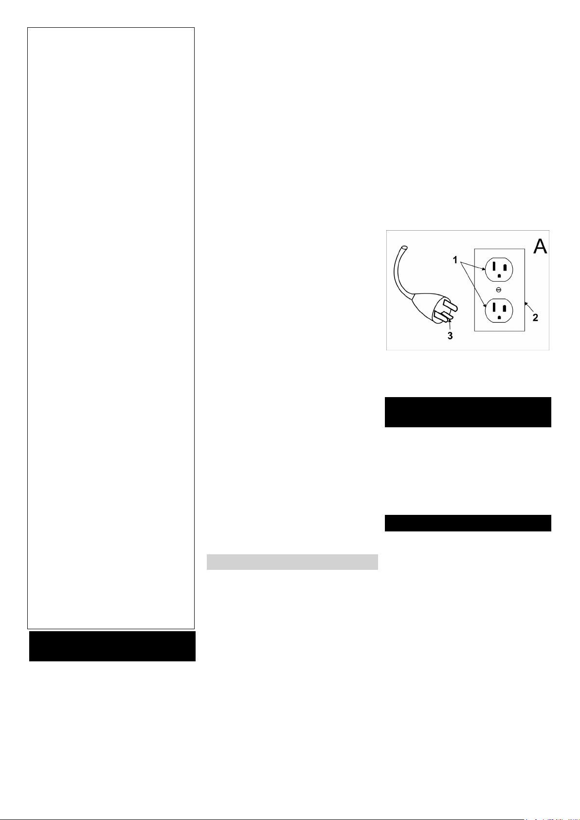
This appliance is for use on a nominal
120-volt circuit and has a grounding attachment plug that looks like the plug
illustrated in sketchpicture A. Make
sure that the appliance is connected to
an outlet having the same configuration as the plug. No adaptor should be
used with this appliance.
CONNECT TO A PROPERLY
GROUNDED OUTLET ONLY
1 Grounded outlet
2 Grounded outlet box
3 Grounded pin
OPERATOR QUALIFICA-
TIONS
Only trained and authorized persons
shall be permitted to operate a powered floor scrubber. Operators of powered floor scrubbers shall be qualified
as to visual, auditory, phisical, and
mental ability to operate the eqipment
safely.
OPERATOR TRAINING
Personnel who have not been trained
to operate powered floor scrubbers
may operate a floor scrubber for the
purposes of training only, and under
the direct supervision of the trainer.
This training should be conducted in an
area away from other trucks, obstacles, and pedestrians.
The operator training program should
include the user’s policies for the site
where the trainee will operate the floor
scrubber, the operating conditions for
that location, and the specific floor
scrubber the trainee will operate. The
training program shall be presented to
all new operators regardless of previous experience.
The training shall inform the trainee
that:
A The primary responsibility of the op-
erator is to use the powered floor
- 1
3EN
Page 4

scrubber safely following the instructions given in the training program.
B Unsafe or improper operation of a
powered floor scrubber can result
in: death or serious injury to the operator or others; damage to the
powered floor scrubber or other
property.
The training program shall emphasize
safe and proper operation to avoid injury to the operator and others and prevent property damage, and shall cover
the following areas.
A Fundamentals of the powered floor
scrubber(s) the trainee will operate:
1 characteristics of the powered floor
scrubber(s), including variations
between powered floor scrubbers in
the workplace;
2 similarities to and differences from
automobiles;
3 significance of nameplate data,
warnings, and instructions affixed
to the powered floor scrubber;
4 operating instructions and warnings
in the operating manual for the
powered floor scrubber, and instructions for inspection and maintenance to be performed by the
operator;
5 type of motive power and its char-
acteristics;
6 method of steering;
7 braking method and characteristics;
8 visibility forward and reverse;
9 stability characteristics with and
without load, with and without at-
tachments;
10 controls-location, function, method
of operation, identification of sym-
bols;
11 battery charging;
12 guards and protective devices for
the specific type of powered floor
scrubber;
13 other caracteristics of the specific
powered floor scrubber.
B Operating enviroment and its effect
on powered floor scrubber operation,
including:
1 floor or ground conditons including
temporary conditions;
2 ramps and inclines;
3 battery charging facilities;
4 narrow aisles, doorways, overhead
wires and piping, and other areas of
limited clearance;
5 areas where the powered floor
scrubber may be operated near
other powered industrial trucks,
other vehicles, or pedestrians;
6 use and capacity of elevators;
7 operation near edge of dock or
edge of improved surface;
8 other special operating conditions
and hazards which may be encountered.
C Operation of the powered floor
scrubber, including:
1 proper preshift inspection and ap-
proved method for removing from
service a powered floor scrubber
which is in need or repair;
2 travelling, turning corners;
3 parking and shutdown procedures;
4 other special operating conditions
for the specific application.
D Operating safety rules and practic-
es, including:
1 provisions of this Standard in Sec-
tion „operating safety rules and
practices“;
2 other rules, regulations, or practic-
es specified by the employer at the
location where the powered floor
scrubber will be used.
E Operational training practice, in-
cluding:
1 if feasible, practice in the operation
of powered floor scrubbers shall be
conducted in an area separate from
other workplace activities and per-
sonnel;
2 training practice shall be conducted
under the supervision of the trainer;
3 training practice shall include the
actual operation or simulated per-
formance of all operating tasks
such maneuvereing, travelling,
stopping, starting, and other activi-
ties under the conditions which will
be encountered in the use of the
powered floor scrubber.
TESTING, RETRAINING AND
ENFORCEMENT
A During training, performance and
oral and/or written tests shall be
given by the employer to measure
the skill and knowledge of the oper-
ator in meeting the requirements of
the Standard. Employers may dele-
gate such testing to others but shall
remain responsible for testing. Ap-
propiriate records shall be kept.
B Operators shall be retrained when
new equipment is introduced, exist-
ing equipment is modified, operat-
ing conditions change, or an
operator’s performance is unsatis-
factory.
C The user shall be responsible for
enforcing the safe use of the pow-
ered floor scrubber according to the
provisions of this Standard.
NOTE: Information on operator training is available from such sources as
powered floor scrubber manufacturers,
government agencies dealing with employee safety, trade organizations of
users of powered industrial trucks,
public and private organizations, and
safety consultants.
OPERATING SAFETY RULES
AND PRACTICES
Operator Responsibility
Save operation is in the responsibility
of the operator.
The operator shall develop safe working habits and also be aware of hazardous conditions in order to protect
himself, other personnel, the powered
floor scrubber, and other material.
The operator shall be familiar with the
operation and function of all controls
and instruments before undertaking to
operate the unit.
Before operating the unit, operators
shall have read and be familiar with the
operator’s manual for the particular
unit being operated and they shall also
abide by the safety rules and practices
in the following paragraphs.
Before operating any unit, the operator
shall be familiar with unusual operating
conditions which may require additional safety precautions or special operating instructions.
General
Before starting to operate the powered
floor scrubber:
A be in operating position;
B place directional controls in neutral;
C apply brake;
D turn switch to ON position.
Do not start or operate the unit, any of
its functions or attachments, from any
place other than from the designated
operators position.
Keep hands and feet inside the operator’s designated area or compartment
of the unit.
Understand unit limitations and operate the unit in a safe manner so as not
to cause injury to personnel. Safeguard pedestrians at all times.
A Do not drive a powered floor scrub-
ber up to anyone standing in front of
an object.
B Ensure that personnel stand clear
of the rear swing area before conducting turning maneuvers.
C Exercise particular care at cross
aisles, doorways, and other locations where pedestrians may step
4 EN
- 2
Page 5

into the path of travel of the powered floor scrubber.
Do not permit passengers to ride on
powered floor scrubbers unless a safe
place to ride has been provided by the
manufacturer.
A powered floor scrubber is attended
when the operator is less than 25 ft.
(7.6 m) from the unit, which remains in
his view.
A powered floor scrubber is unattended when the operator is more than 25
ft. (7.6 m) from the unit, which remains
in his view, or whenever the operator
leaves the unit and it is not in his view.
Before leaving the operator’s position:
A bring the unit to a complete stop;
B place the directional controls in
neutral;
C apply the parking brake;
D stop the engine or turn off the con-
trols;
E if the unit must be on an incline,
block the wheels.
Maintain a safe distance from the edge
of ramps, platforms, and other similar
working surfaces.
When powered floor scrubbers are
driven on and off highway trucks or
trailers, the brakes on the highway
trucks or trailers shall be applied and
wheel chocks or other positive mechanical means shall be used to prevent unintentional movement of
highway trucks and trailers.
Whenever powered floor scrubbers
are driven on and off semitrailers that
are not coupled to a tractor, supports
may be needed to prevent upending or
corner dipping.
Care shall be taken not to contact overhead installations such as lights, wiring, pipes, sprinkler systems, etc.
Report all accidents involving personnel, building structures, and equipment
to the supervisor or as directed.
Do not add to, or modify the unit.
Do not block access to fire aisles, stairways or fire equipment.
Travelling
Observe all traffic regulations including
authorized plant speed limits. Under
normal traffic conditions, keep to the
right. Maintain a safe distance, based
on speed of travel, from the unit ahead;
and keep the unit under control at all
times.
Yield the right of way to pedestrians
and emergency vehicles such as ambulances and fire trucks.
Do not pass another truck travelling in
the same direction at intersections,
blind spots, or at other dangerous locations.
Slow down and sound the audible
warning device(s) at cross aisles and
other locations where vision is obstructed.
Cross railroad tracks at an angle wherever possible. Do not park closer than
6 ft (1800 mm) to the nearest rail of a
railroad track.
Ascend or descend grades slowly, and
with caution. Avoid turning, if possible,
and use extreme caution on grades,
ramps, or inclines; normally travel
straight up and down.
Keep a clear view of the path of travel
and observe for other traffic, personnel, and safe clearances.
Under all travel conditions, operate the
unit at a speed that will permit it to be
brought to a stop in a safe manner.
Make starts, stops, turns, or direction
reversals in a smooth manner so as
not to shift load and/or overturn the
powered floor scrubber.
Do not indulge in stunt driving or horseplay.
Slow down for wet and slippery floors.
Before driving over a dockboard or
bridge plate, be sure that it is properly
secured. Drive carefully and slowly
across the dockboard or bridge plate,
and never exceed its rated capacity.
Do not drive powered floor scrubbers
onto any elevator unless specifically
authorized to do so. Approach elevators slowly, and then enter squarely after the elevator car is properly leveled.
Once on the elevator, neutralize the
controls, shut off power, and set
brakes. It is advisable that all other personnel leave the elevator before the
powered floor scrubber is allowed to
enter or leave.
When negotiating turns, reduce speed
to a safe level consistent with the operating environment. Make the turns
smoothly. Except when maneuvering
at a very low speed, turn the steering
control at a moderate, even rate.
The operation of a powered floor
scrubber requires special safety considerations, as follows:
A A powered floor scrubber may tip
over if an operator fails to slow down to
a safe speed before making turns. Indications that a truck is being driven at
an excessive speed during turning maneuvers include:
1 tire skidding;
2 unit side sway;
3 wheel lift; and
4 the need to grip the steering wheel
tightly to keep from sliding out of the
seat.
B The likelihood of lateral tipover is increased under any of the following
conditions, or combinations of them:
1 travelling on an uneven surface;
2 travelling at excessive speed.
C
Tipping forward can occur and its likeliehood is increased under the following
conditions, or combination of them:
1 The operator should stay with the
powered floor scrubber if it falls off
a loading dock or ramp. The operator should hold on firmly and lean
away from the point of ipact.
2 Where the enviroment presents a
severe hazard, or there are other
unusual operating conditions, the
user may need to establish different
and/or additional safety precautions
and special operating instructions
appropriate for the conditions.
Operator care of the unit
At the beginning of each shift and before operating the powered floor scrubber, check its condition, giving special
attention to the following:
A condition of tires
B if pneumatic tires, check inflation
pressures
C warning and safety devices
D lights
E battery
F controls
G lift and tilt systems
H chains and cables
I limit switches
J brakes
K steering mechanism
L additional items or special equip-
ment as specified by the user and/
or manufacturer
If the unit is found to be in need of re-
pair or in any way unsafe, or contributes to an unsafe condition, the matter
shall be reported immediately to the
user’s designated authority, and the
unit shall not be operated until it has
been restored to safe operating condition.
If during operation the unit becomes
unsafe in any way, the matter shall be
reported immediately to the user’s designated authority, and the unit shall not
be operated until it has been restored
to safe operating condition.
Do not make repairs or adjustments
unless specifically authorized to do so.
Do not use open flames when checking electrolyte level in storage batteries.
- 3
5EN
Page 6

MAINTENANCE AND RE-
BUILD PRACTICES
Operation of the unit may be hazardous if maintenance is neglected or repairs, rebuilds, or adjustments are not
performed in accordance with the manufacturer’s design criteria. Therefore,
maintenance facilities (on or off premises), trained personnel, and detailed
procedures shall be provided.
Parts manuals and maintenance manuals may be obtained by the powered
floor scrubber manufacturer.
In unusual cases not covered by the
manuals referred above, consult the
powered floor scrubber manufacturer.
Maintenance and inspection of the unit
shall be performed in conformance
with the following practices:
A a schedules planned maintenance,
lubrication, and inspection system
shall be followed; consult the manufacturer’s recommendations.
B only tranined and authorized per-
sonnel shall be permitted to maintain, repair, adjust, and inspect the
unit, and in accordance with manufacturer’s specifications.
When lifting powered floor scrubbers
for repair or inspection, the units shall
be lifted in a safe, secure, stable manner. Removal of components such as
counterweights or uprights will change
the center of gravity and may create an
unstable condition.
Before starting inspection and repair of
powered floor scrubber:
A raise drive wheels free of floor and
disconnect battery and use chocks
or other positive truck-posirioning
devices;
B block chassis before working on
them;
C disconnect battery before working
in the electrical system;
D the charger connector shall be
plugged only into the battery connector and never into the unit connector.
Operation of the powered floor scrubber to check the performance shall be
conducted in an authorized area where
safe clearance exists.
A Before starting to operate the unit:
1 be in operating position;
2 apply brake;
3 place directional controls in neutral;
4 turn switch to ON position;
5 check functioning of lift and tilt sys-
tems, steering, warning devices,
and brakes.
B Before leaving the unit:
1 stop unit;
2 place directional control in neutral;
3 apply the parking brake;
4 stopp the engine or turn off the pow-
er;
5 turn off the control circuit;
6 if the unit must be left on an incline,
block the wheels.
Avoid fire hazards and have fire pro-
tection equipment present in the work
area. Do not use an open flame to
check the level of any fluid, especially
battery electrolyte. Do not use open
pans of fuel or flammable cleaning fluids for cleaning parts.
Properly ventilate work area, vent exhaust fumes, and keep shop clean and
dry.
Brakes, steering mechanisms, control
mechanisms, warning devices, lights,
governors, guards and safety devices,
articulating axle stops, and frame
members shall be carefully and regularly inspected and maintained in safe
operating condition.
FIRE SAFETY STANDARD
Any unit not in safe operating condition
shall be removed from service.
Repairs shall not be made in Class I,
Class II, and Class III locations.
Repairs to the electrical system of battery powered floor scrubbers shall be
performed only after the battery has
been disconnected.
Operating Temperature. When the
temperature of any part of any powered floor scrubber is found to be in excess of its normal operating
temperature and creates a hazardous
condition, the vehicle shall be removed
from service and shall not be returned
to service until the cause for such overheating has been eliminated.
Fire Prevention.The unit shall be kept
in a clean condition and reasonably
free of lint, excess oil, and grease.
Noncombustible agents are preferred
for cleaning the unit. Flammable liquids
[those having flash points at or above
100°F (37,8°C)] are not allowed. Precautions regarding toxicity, ventilation,
and fire hazard shall be appropriate for
the agent or solvent used.
Nameplate Visibility. The unit type
designations as shown on the nameplate and the type markers shall not be
covered over with paint so that their
identification information is obscured.
Changing and Charging Storage
Batteries.
This section shall apply to batteries
used on electric trucks. The two types
of batteries commonly are lead and
nickel-iron. They contain corrosive
chemical solutions, either acid or alkali,
and, therefore, present a chemical
hazard. While being charged, they give
off hydrogen and oxygen, which, in
certain concentrations, are explosive.
Battery-charging installations shall be
located in areas designated for that
purpose; such areas shall be kept free
of extraneous combustible materials.
Facilities shall be provided for the following:
A Flushing spilled electrolyte;
B Fire protection;
C Protecting charging apparatus from
damage by trucks, and
D Adequate ventilation for dispersal
of fumes from gasing batteries.
Where on-board chargers are used,
charging shall be accomplished at locations designated for that prupose,
taking into account the electrical requirements of the charger and facilities
for fire protection.
Exception: Flushing facilities shall not
be required if charging is accomplished
without removing the battery from the
vehicle.
Where handling acid concentrates
greater than 50 percent acid (above
1.400 specific gravity) an eye-wash
fountain shall be provided.
A conveyor, overhead hoist, or equivalent material handling equipment shall
be provided for handling batteries.
Chain hoists shall be equipped with
load-chain containers. Where a hand
hoist is used, uncovered batteries shall
be covered with a sheet of plywood or
other nonconducting material to prevent the hand chain from shorting in
cell connectors or terminals. A properly
insulated spreader bar shall be used
with any overhead hoist.
Reinstalled or new batteries shall meet
or exceed the battery type marked on
the unit. Reinstalled batteries shall be
positioned properly and secured in the
unit.
A carboy tilter or siphon shall be provided where acid in carboys is used.
Where diluting concentrated sulfuric
acid to make up elektrolyte, the acid
ALWAYS shall be added to the water –
not reverse. Battery maintenance personnel shall wear protective clothing
such as eye protection, long sleeves,
and gloves.
Exception: Removal and replacement
of batteries shall not require the use of
protective clothing.
Electrical installations shall be in accordance with NFPA 70, National electric code, and any local ordinances.
6 EN
- 4
Page 7

Trained and authorized personnel
shall change or charge batteries.
The powered floor scrubber shall be
positioned properly and brakes shall
be applied before attempting to change
or charge batteries.
Where charging batteries, the vent
caps shall be kept in place to avoid
electrolyte spray. Care shall be taken
to ensure that vent caps are functionning. The battery (or compartment)
cover(s) shall be open to dissipate heat
and gas.
Smoking shall be prohibited in the
charging area.
Precautions shall be taken to prevent
open flames, sparks, or electric arcs in
battery-charging areas.
Tools and other metallic objects shall
be kept away from the tops of uncovered batteries.
The unit shall not be used in classified
areas.
- 5
7EN
Page 8
Please read and comply with
these original instructions
prior to the initial operation of your appliance and store them for later use or
subsequent owners.
Contents
Safety instructions . . . . . . . EN . . 6
Function . . . . . . . . . . . . . . . EN . . 6
Proper use . . . . . . . . . . . . . EN . . 6
Environmental protection . . EN . . 6
Control elements. . . . . . . . . EN . . 7
Before Startup. . . . . . . . . . . EN . . 8
Operation . . . . . . . . . . . . . . EN . 10
Grey Intelligent Key . . . . . . EN . 12
Transport. . . . . . . . . . . . . . . EN . 11
Storage . . . . . . . . . . . . . . . . EN . 13
Maintenance and care . . . . EN . 13
Troubleshooting . . . . . . . . . EN . 16
Technical specifications . . . EN . 18
Accessories and Spare Parts EN . 19
Warranty . . . . . . . . . . . . . . . EN . 19
Safety instructions
Before using the appliance for the first
time, read and observe these operating instructions and the accompanying
brochure: Safety information for brush
cleaning units and spray-extraction
units, 5.956-251.
The appliance has been approved for
use on surfaces with max. gradients as
listed under "Technical Specifications".
Safety Devices
Safety devices serve to protect the
user and must not be rendered in operational or their functions bypassed.
Safety button
To take all functions out of operation
immediately: Bring the safety switch
into the "0" position.
– When switching off the safety
switch, the appliances brakes hard.
– The emergency-stop has a direct
effect on all machine functions.
Seat switch
Switches off the drive motor after a
short delay, if the operator leaves the
operator seat during operation or while
moving.
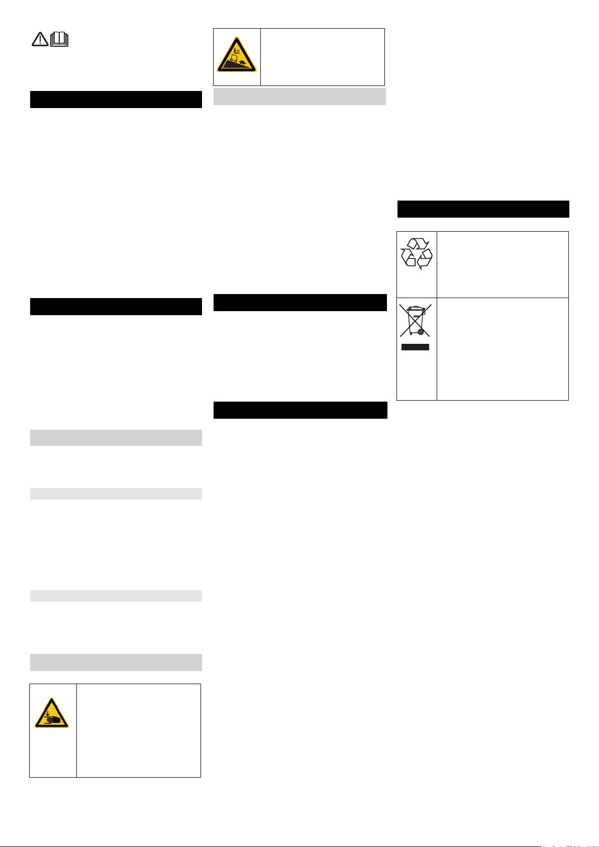
Symbols on the machine
CAUTION
Risk of injury on account
of being crushed.
Keep hands away from
this area while swivelling
down the waste water
tank.
DANGER
Increased risk of accidents due to high speed.
Drive slowly on slopes.
Danger or hazard levels
DANGER
Immediate danger that can cause severe injury or even death.
몇 WARNING
Possible hazardous situation that
could lead to severe injury or even
death.
CAUTION
Pointer to a possibly dangerous situation, which can lead to minor injuries.
ATTENTION
Pointer to a possibly dangerous situation, which can lead to property damage.
Function
The scrubber vacuum is used for wet
cleaning or polishing of level floors.
You can adjust the machine to suit the
cleaning task by modifying the settings
for water quantity, contact pressure of
the brushes, detergent quantity and
driving speed.
Proper use
Use this appliance only as directed in
these operating instructions.
– The appliance may only be used for
the cleaning of hard surfaces that
are not sensitive to moisture and
polishing operations.
– This appliance is intended for inside
use.
– The application temperature ranges
from +5°C to +40°C.
– The appliance is not suited for the
cleaning of frozen grounds (e.g. in
cold stores).
– The appliance is suitable for a max.
water depth of 1 cm. Do not drive
into an area where there is a risk of
this max. water height being exceeded.
– The appliance may only be
equipped with original accessories
and spare parts.
– The appliance is not intended for
the cleaning of public traffic routes.
– The machine should not be used on
surfaces that are sensitive to pressure. Please consider the allowed
load per surface unit of the floor.
Details of load per surface unit can
be found in the technical data.
– The appliance is not suited for the
use in potentially explosive environments.
– The machine should not be used to
suck in inflammable gases, undiluted acids or solvents.
This includes petrol, thinning
agents or hot oil that can form an
explosive mixture when it comes in
contact with sucked air. Do not use
acetone, undiluted acids and solvents as they are aggressive towards the materials from which the
appliance is made.
Environmental protection
The packaging materials
are recyclable. Please do
not throw packaging in the
domestic waste but pass it
on for recycling.
Old units contain valuable
recyclable materials. Batteries, oil and similar substances may not be released into
the environment. Therefore
please dispose of old units
through suitable collection
systems.
Notes about the ingredients
(REACH)
You will find current information about
the ingredients at:
www.kaercher.com/REACH
8 EN
- 6
Page 9
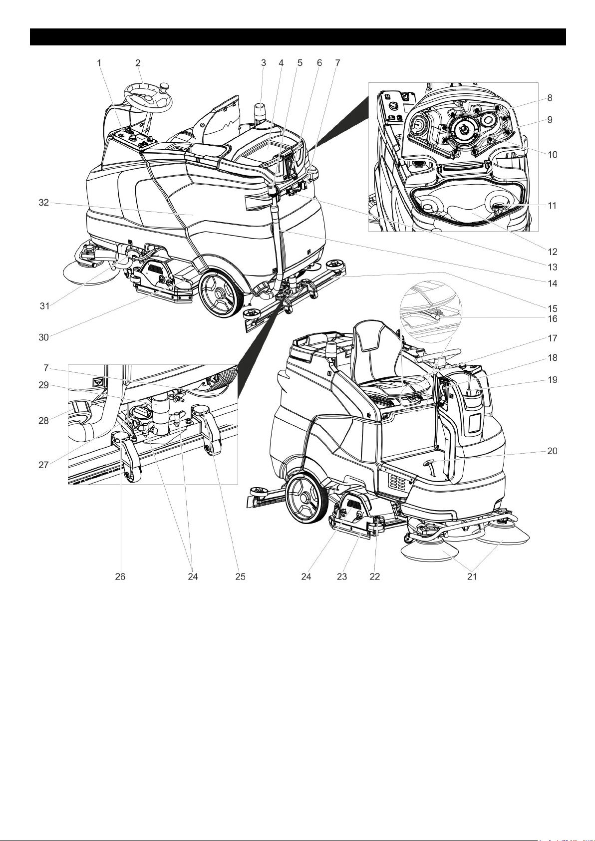
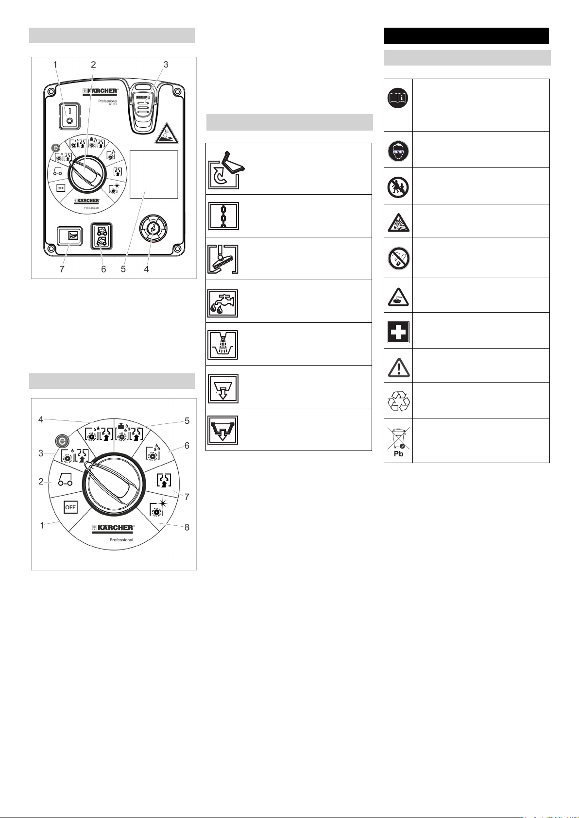
Control elements
1 Operating field
2 Steering wheel
3 Warning lamp **
4 Storage surface for cleaning set
"Home base box“
5 Dosing equipment for dirt water
6 Water connection for wastewater
tank rinsing system **
7 Mop holder **
8 Wastewater tank rinsing system **
9 Cover dirt water reservoir
10 Float
11 Fluff filter
12 Dirt water reservoir
13 Tool holder **
14 Dirt water discharge hose
15 Vacuum bar *
16 Lever for seat adjustment
17 Seat (with seat switch)
18 Filling system **
19 Fresh water tank cover
20 Drive pedal
21 Side brush (only SB version)
22 Adjustment wheel for wiping flap*
23 Wiping flap
24 Cleaning head *
25 Height adjustment of suction bar
26 Wing nuts for fastening the vacuum
bar
27 Rotary handle to incline the vacuum
bar
28 Lock, dirt water reservoir
29 Suction hose
- 7
30 Waste container (only with R clean-
ing head) *
31 Closure fresh water tank with fresh
water filter
32 Battery
* not included in the delivery
** option
9EN
Page 10
Operator console
Wet clean the floor and allow the
detergent to react.
7 Vacuuming
Suck in the dirt fleet.
8 Polishing
Polishing the floor without the appli-
cation of liquid.
Symbols on the machine
Handle for swivelling up the
waste water tank
Lashing point
Before Startup
Batteries
Observe the directions on the
battery, in the instructions for
use and in the vehicle operating instructions
Wear eye protection
Keep children away from acid
and batteries
Danger of explosion
1 Safety button
2 Programme switch
3 Intelligent Key
4 Info button
5 Display
6 Drive direction switch
7 Horn
Programme switch
1 OFF
Device is switched off
2 Transport run
Driving to the Place of Use.
3 Eco programme
Wet clean the floor (with reduced
brush speed) and vacuum up
wastewater (with reduced suction).
4 Scrubbing suction
Wet clean the floor and vacuum up
dirt water.
5 Heavy programme
Wet clean the floor (with increased
brush contact pressure) and vacuum up dirt water.
6 Scrubbing
** option
Mop holder **
Water connection filling
system **
Water connection for
wastewater tank rinsing
system **
Drain outlet fresh water
tank
Drain outlet waste water
tank
Fire, sparks, naked flames
and smoking must be strictly
avoided
Danger of chemical burns
First aid
Warning note
Disposal
Do not throw the battery into
the regular waste
DANGER
Risk of explosion!
Do not place tools or similar items on
the battery. Risk of short-circuit and explosion.
Risk of injury. Ensure that wounds never come into contact with lead. Always
clean your hands after having worked
with batteries.
10 EN
- 8
Page 11
Recommended batteries
NOTICE
Average charging time is approx. 10 12 hours.
} *
3
/h] **
3
The recommended chargers (matching the batteries used) are regulated
electronically and will automatically
switch off the charging process.
Battery set
240Ah,
Order No.
4.035-
987.7
Volume [m
Air flow [m
27 10,8
trough, lowmaintenance
Battery set
180Ah,
4.035-
988.7
20,25 8,1
trough, lowmaintenance
Battery set
240Ah, 6
4.654-
306.7
6,975 2,79
blocks, maintenance-free
Battery set
180Ah, 6
4.654-
307.7
5,175 2,07
blocks, maintenance-free
* Minimum volume of the battery
charging room
** Minimum air flow between the battery charging room and the surroundings
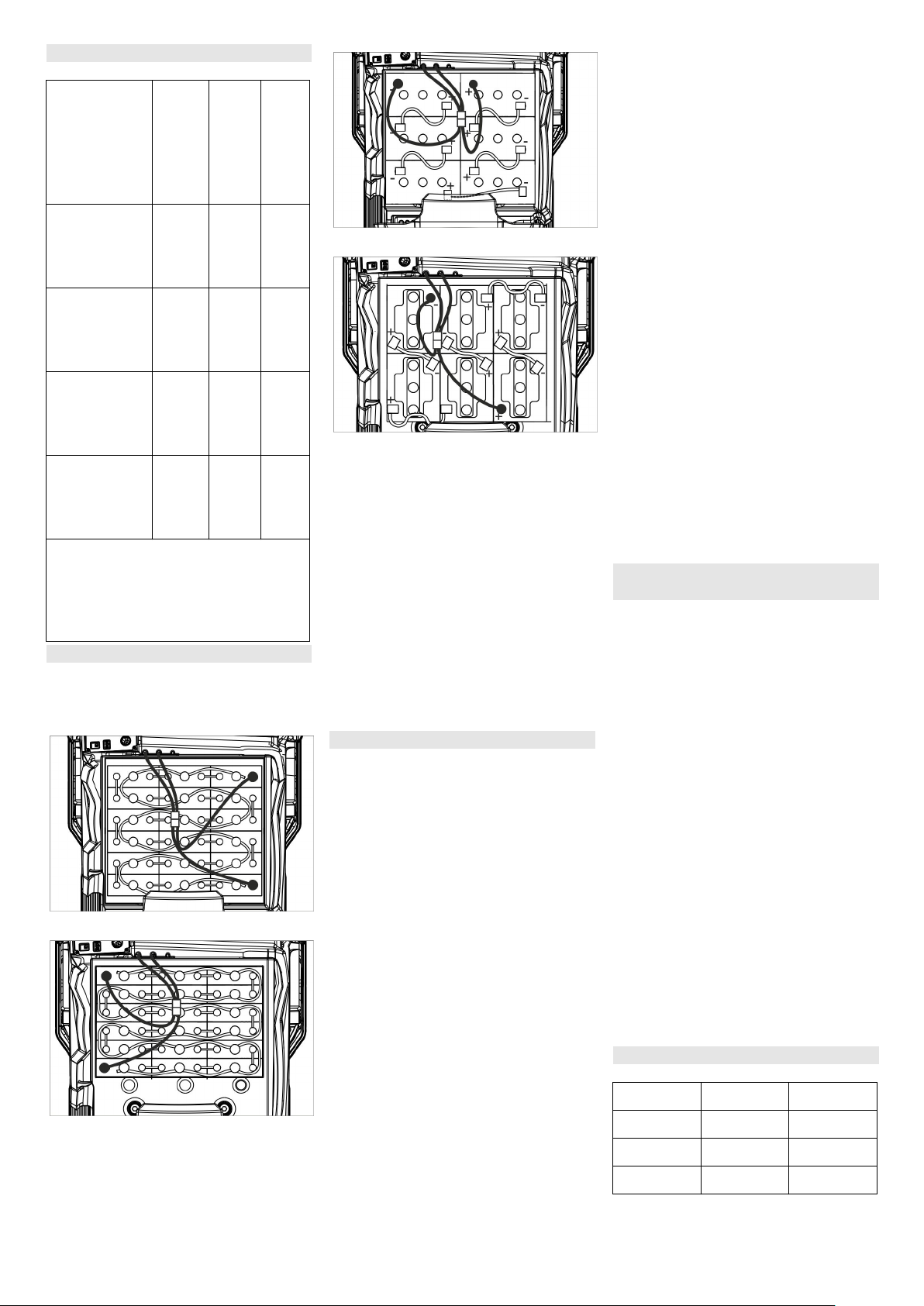
Insert batteries and connect
Bring the safety switch into the "0"
position.
Tilt the wastewater tank backwards.
4.035-987.7
4.035-988.7
4.654-306.7 (arrangement A)
4.654-307.7 (arrangement B)
ATTENTION
Risk of damage. Ensure correct polarity.
Lubricate the battery pole with pole
grease.
Connect pole using the enclosed
connecting cable.
Connect the connection cable to
the free battery poles (+) and (-).
Insert battery plug.
ATTENTION
Risk of damage due to full discharge!
Charge the batteries before commissioning the appliance.
Charge the batteries
NOTICE
The appliance is equipped with a total
discharge protection, i.e. if the still admissible minimum of the capacity is
reached, the appliance can only be
driven. The display shows the message "Battery low - cleaning not possible" and "Battery empty - please
charge".
Drive the appliance directly to the
charging station; avoid any steep
gradients in the process.
NOTICE
While using other batteries (for e.g.
batteries from other manufacturers)
the total discharge protection level
must be reset by the Kärcher aftersales service according to the respective battery.
DANGER
Risk of electric shock. Observe supply
network and fuse protection - see
"Charger". Only use the charger in dry
rooms with sufficient ventilation!
DANGER
Danger of explosion. The room, where
the machine is kept to charge the battery, must feature a minimum volume
and an air exchange with a minimum
flow rate, depending on the type of battery (see "Recommended Batteries").
Danger of explosion. The charging of
wet batteries is only permitted if the
waste water reservoir is tilted up.
Swivel the wastewater tank up-
wards.
Separate the battery plug and con-
nect the charger cable.
Plug in the mains plug of the char-
ger.
Execute the charging process ac-
cording to the seperate instrucion
manual of the battery charger.
Low maintenance batteries (wet batteries)
Add distilled water one hour before
the charging process comes to an
end; follow the correct acid level.
There are corresponding indicators
on the battery. At the end of the
charging process, all cells must
gas.
DANGER
Danger of chemical burns. Filling water
in while the battery is discharged can
lead to acid leaks!
Wear goggles when handling battery
acid and adhere to instructions to prevent injuries and damage to clothing.
Flush any acid drops on the skin or
clothes immediately with plenty of water.
ATTENTION
Use only distilled or desalinated water
(EN 50272-T3) for filling the battery.
Do not add any substances (so-called
performance improving agents), else
warranty claims will not be entertained.
Maximum battery dimensions
Layout A B
Length 244 mm 312 mm
Width 190 mm 182 mm
Height 275 mm 365mm
- 9
11EN
Page 12
Information on the initial charge
With the initial charge, the control will
not yet be able to detect which battery
type has been installed. Keep charging
the batteries until the display shows a
full charge (batteries may still not be
completely charged). The next charging process will have an accurate display and charge power and the
batteries will be fully charged.
Note:
A "V" to the right of the bar of the battery indicator shows that the initial
charge has not been performed yet.
Use the appliance until the deep discharge protection switches off the
brush motor and the turbine after the
initial charge of the battery. This procedure is necessary to adjust the battery
indicator. Only then the correct battery
status is displayed.
Removing the batteries
Bring the safety switch into the "0"
position.
Tilt the wastewater tank backwards.
Clamp off the minus pole of the bat-
tery.
Clamp off the remaining cables
from the battery.
Remove the batteries.
Dispose of the used batteries ac-
cording to the local provisions.
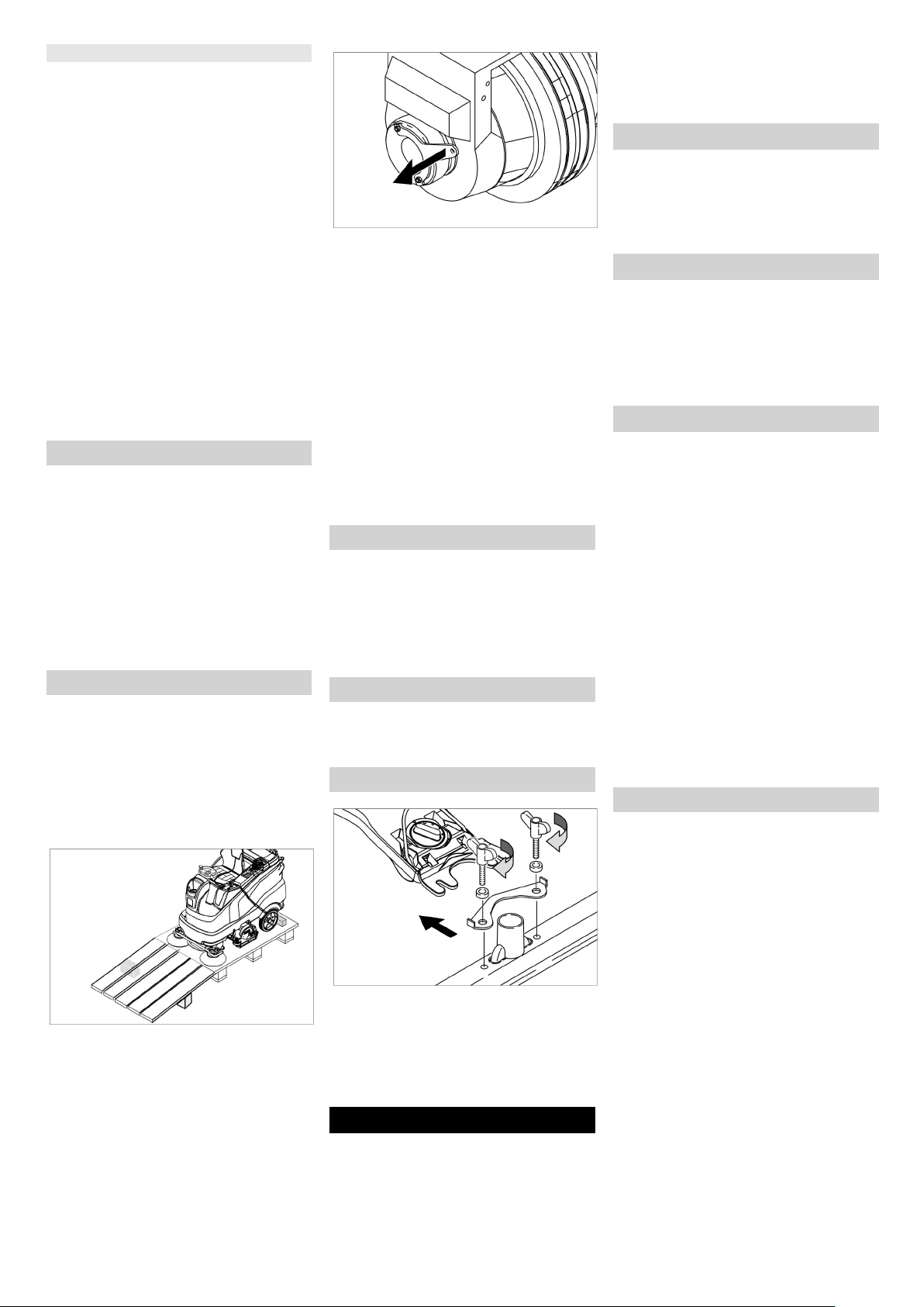
Unloading
NOTICE
To take all functions out of operation
immediately, bring the safety switch
into the "0" position.
Four floor boards of the pallet are
fastened with screws. Unscrew
these boards.
Place the boards on the edge of the
pallet. Place the boards in such a
way that they lie in front of the four
wheels of the machine. Fasten the
boards with screws.
Slide the four support beams in-
cluded in the packaging under the
ramp.
Remove the wooden bars in front of
the wheels.
Pull the brake lever and push the
appliance down the ramp with the
level pulled.
or
Plug in the Intelligent Key.
Bring the safety switch into the "1"
position.
Set programme selector switch to
transport run.
Set the travel direction switch to
"forward".
Actuate the accelerator pedal.
Drive the appliance off the pallet.
Bring the safety switch into the "0"
position.
Install cleaning head
The procedure for changing the cleaning head is described in the chapter
"Maintenance Tasks".
NOTICE
On some models, the cleaning head is
already installed.
Installing the Brushes
The installation of the brushes is described in the chapter "Maintenance
Tasks".
Installing the Vacuum Bar
Insert the vacuum bar into the vac-
uum bar suspension in such a man-
ner that the profiled sheet is
positioned above the suspension.
Tighten the wing nuts.
Insert the suction hose.
Operation
DANGER
Risk of injuries. Never use the unit
without protective roof in areas where
the operators can be hit by dropping
objects.
NOTICE
To take all functions out of operation
immediately, bring the safety switch
into the "0" position.
Adjusting driver's seat
Operate the lever for the seat ad-
justment and move the seat to the
desired position.
Release the seat adjustment lever
and lock the seat in place.
Turning on the Appliance
Take the seating position.
Plug in the Intelligent Key.
Bring the safety switch into the "1"
position.
Turn the programme switch to the
desired function.
Check parking brake
DANGER
Risk of accident. Prior to every operation, the parking brake must be
checked for proper function on a level
ground.
Turn on the appliance.
Set the travel direction switch to
"forward".
Set programme selector switch to
transport run.
Gently depress drive pedal.
The brake must unlock audibly. The
machine must roll easily on a plane
surface. When the pedal is released, the brake locks audibly.
Switch off the machine and call the
aftersales service if the above-mentioned events do not occur.
Driving
DANGER
Danger of accident. If the machine
does not brake, then proceed as follows:
If the appliance does not stop when
the accelerator is released on a
ramp with more than 2% inclination,
the safety switch may only be
brought in the "0" position if the
proper mechanical function of the
parking brake has been checked
prior to every operation of the appliance for safety reasons.
Switch off the machine only after it
comes to a complete halt (on an
even surface) and call up the aftersales service!
Further, follow all warning instruc-
tions for braking.
12 EN
- 10
Page 13
DANGER
Danger of tipping if gradient is too high.
The gradient in the direction of trav-
el should not exceed 10% (Adv
15%).
Drive only lengthwise on uphill and
downhill gradients, do not turn.
Danger of tipping when driving round
bends at high speed.
Danger of slipping on wet floors.
Drive slowly when cornering.
Danger of tipping on unstable ground.
Only use the machine on sound
surfaces.
Danger of tipping with excessive sideways tilt.
Driving
Take the seating position.
Plug in the Intelligent Key.
Bring the safety switch into the "1"
position.
Set programme selector switch to
transport run.
Set the drive direction using the
drive direction button at the operator console.
Determine the driving speed by
pressing the drive pedal.
Stop the machine: Release the
drive pedal.
NOTICE
The drive direction can also be
changed during the drive. Thus, very
blunt edges can be polished by moving
forward and backward a few times.
Overload
In case of overloading, the drive motor
automatically switches off after a certain period. A fault message is displayed on the console. The concerned
unit gets switched off if the controls get
overheated.
Allow machine to cool down at least
for 15 minutes.
Turn the programme switch to
"OFF", wait for a short period of
time and turn it back to the desired
programme.
Filling in detergents
Detergent
ATTENTION
Risk of damage. Only use the recommended detergents. With respect to
different detergents the operator bears
the increased risk regarding the operational safety and danger of accident.
Only use detergents that are free from
solvents, hydrochloric acid and hydrofluoric acid.
Follow the safety instructions for using
detergents.
Note
Do not use highly foaming detergents.
Recommended detergents:
Application Detergent
Routine cleaning of all
water resistant floors
Routine cleaning of
RM 746
RM 780
RM 755 es
glossy surfaces (e.g.
granite)
Routine cleaning and
basic cleaning of indus-
RM 69
ASF
trial floors
Routine cleaning and
RM 753
basic cleaning of fine
stoneware tiles
Routine cleaning of tiles
RM 751
in sanitary areas
Cleaning and disinfec-
RM 732
tion in sanitary areas
Removal of coating
RM 752
from all alkali-resistant
floors (e.g. PVC)
Removal of coating
RM 754
from linoleum floors
Fresh water
Open the cover of the fresh water
reservoir.
Fill fresh water (max. 60 °C) until 15
mm below the upper edge of the
tank.
Pour in detergent.
NOTICE
If detergent is added to the cleaning
detergent tank first, followed by water,
there could be a lot of foam.
Close the cover of the fresh water
reservoir.
NOTICE
Fill up the fresh water tank completely
before starting up the machine to ventilate the water supply system.
Filling system (optional)
Connect the water hose to the con-
nection neck on the filling system.
Open the water supply.
Once the maximum fill level is
reached, the built-in floater valve
will stop the water inflow.
Shut off water supply.
Remove the water hose.
Setting the parameters
With yellow Intelligent Key
Parameters for the different cleaning
programmes are preset in the appliance.
Depending on the authorisation of the
yellow Intelligent Key, individual parameters can be changed.
The modification of the parameters is
only valid until another cleaning programme is selected via the programme
selection switch.
If you wish to permanently change the
parameters, you must use a grey Intelligent Key. This adjustment procedure
is described in the section "Grey Intelligent Key“.
Note:
Almost all displayed text regarding parameter adjustment is self-explanatory. The only exception is the parameter
FACT:
– Fine Clean: Lower brush speed for
removing the grey film on fine stone
floors.
– Whisper Clean: Medium brush
speed for regular cleaning with reduced noise level.
–
Power Clean: High brush speed for
polishing, crystallising and sweeping.
Turn the program selection switch
to the desired cleaning program.
Turn the info button until the de-
sired parameter is displayed.
Press Info button - the set value
blinks.
Set the desired value by turning the
info button.
Confirm the changed setting by
pressing the Info button or wait till
the set value is automatically accepted after 10 seconds.
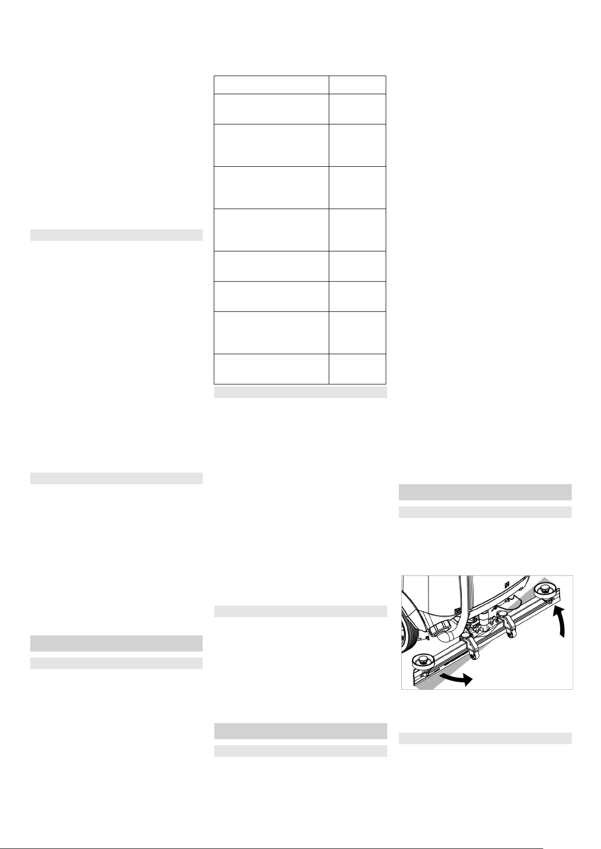
Setting the Vacuum Bar
Oblique position
To improve the vacuuming result on
tiled floors the vacuum bar can be
turned to an oblique position of up to
5°.
Release the wing nuts.
Turn the vacuum bar.
Tighten the wing nuts.
Inclination
If the vacuum result is unsatisfactory
the inclination of the straight vacuum
bar can be modified.
Adjust the rotary handle to incline
the suction bar.
- 11
13EN
Page 14
Adjust wiping flaps
Adjust the wiper flaps by turning the
adjustment wheel so that they
touch the floor.
Turn the adjustment wheel an addi-
tional turn toward the bottom.
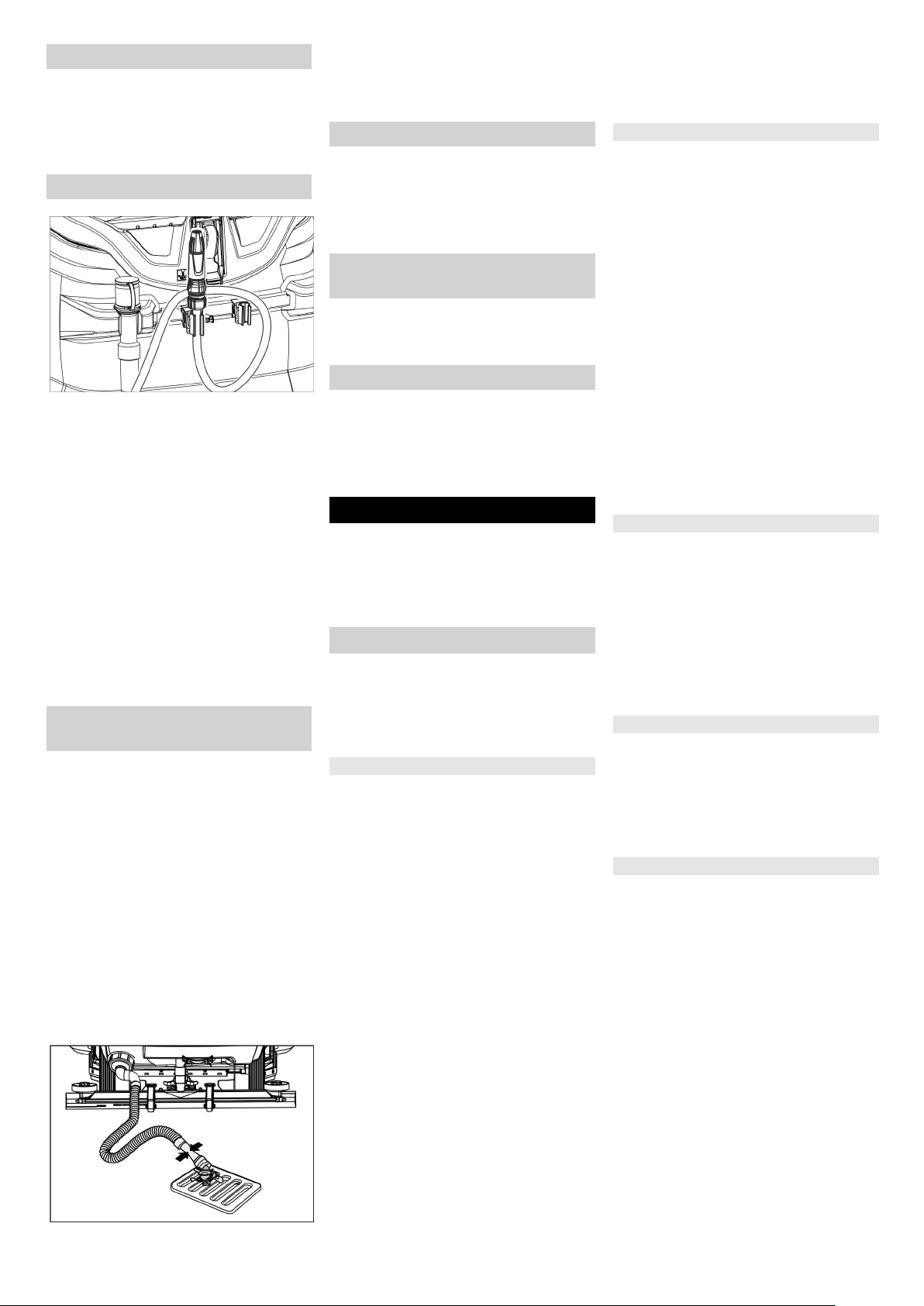
Spray nozzle (option)
The hose with the spray nozzle is attached to the back of the appliance. It
serves for washing away dirt and for
manual cleaning of the wastewater
tank.
Turn programme selector switch to
"transport run".
Press Info button.
Turn the info button until "tank rins-
ing" is shown on the display.
Press Info button.
Turn the info button until "ON" is
displayed.
Press Info button.
The water pump delivers fresh water through the spray nozzle.
Emptying the Dirt Water Reser-
voir
NOTICE
Overflow wastewater tank. When the
wastewater tank is full, the suction turbine switches off and "Wastewater
tank full" is shown on the display.
몇 WARNING
Please observe the local provisions regarding the wastewater treatment.
Take the dirt water discharge hose
from the support and lower above a
suited collection device.
NOTICE
The wastewater flow can be controlled
by squeezing the dosing unit.
Let off water by opening the dosage
device at the discharge hose.
The rinse the dirt water reservoir
with clear water.
Emptying the Fresh Water Tank
Open the lock of the fresh water
reservoir.
Drain the fresh water.
Attach the closure of the fresh wa-
ter tank.
Empty waste container (only
with R cleaning head)
Check the waste container. If need-
ed, remove and empty waste container after work.
Shutting down
Remove the Intelligent Key.
Secure the machine with wheel
chocks to prevent it from rolling
away.
Charge battery, if required.
Grey Intelligent Key
Plug in the Intelligent Key.
Select the desired function by turn-
ing the Info button.
The different functions are described in
the following.
Transport run
Turn programme selector switch to
"transport run".
Press Info button.
In the transport run menu the following
settings can be made:
Key management
In this menu item the authorisations for
yellow intelligent keys as well as the
language of the display texts are selected.
Turn the info button until "key man-
agem." is shown on the display.
Press Info button.
Remove the grey Intelligent Key
and insert the yellow Intelligent Key
to be programmed.
Select the desired menu item to be
modified by turning the Info button.
Press Info button.
Adjust the menu item by turning the
Info button.
Confirm the setting by pressing the
menu item.
Select the next menu item to be
modified by turning the Info button.
In order to save the authorisations,
call the "Save?" menu by turning
the info button and then press the
info button.
"Continue key menu":
Yes: Programme further Intelligent
Key.
No: Exit key menu.
Press Info button.
Selecting the brush shape
This function is required when changing the cleaning head.
Turn the info button until "brush
head" is shown on the display.
Press Info button.
Turn the info button until the de-
sired brush shape is highlighted.
Press Info button.
Move the hoist drive for replace-
ment of the cleaning head by turning the info button:
up: Raise
down: Lower
OFF: Stop
Exit menu: Select "OFF" by turning
the info button and press the info
button.
When exiting the menu, the control
performs a restart.
Stopping times
Turn the info button until "stopping
times" is shown on the display.
Press Info button.
Turn the info button until the de-
sired assembly is highlighted.
Press Info button.
Turn the info button until the de-
sired stopping time is reached.
Press Info button.
Setting the battery type
Turn the info button until "Battery
menu" is displayed.
Press Info button.
Turn the info button until the de-
sired battery type is highlighted.
Press Info button.
Standard setting
Changes of the parameters of the individual cleaning programmes that were
made during the operation are reset to
the basic setting after switching off the
appliance.
Turn the info button until "Basic set-
ting" is displayed.
Press Info button.
Turn the info button until the de-
sired cleaning programme is displayed.
Press Info button.
Turn the info button until the de-
sired parameter is displayed.
Press Info button - the set value
blinks.
Set the desired value by turning the
info button.
Press Info button.
14 EN
- 12
Page 15
Setting the language
Turn the info button until "Lan-
guage" is displayed.
Press Info button.
Turn the info button until the de-
sired language is highlighted.
Press Info button.
Factory setting
The factory settings of all parameters
are restored.
Cleaning Programs
Parameters that are adjusted with the
grey Intelligent Key, are kept until another setting is selected.
Turn the program selection switch
to the desired cleaning program.
Press the info button - the first ad-
justable parameter is displayed.
Press Info button - the set value
blinks.
Set the desired value by turning the
info button.
Confirm the changed setting by
pressing the Info button or wait till
the set value is automatically accepted after 10 seconds.
Select the next parameter by turn-
ing the Info button.
After all desired parameters have
been modified, turn the info button
until "Exit menu" is displayed.
Press the info button - you will exit
the menu.
Transport
DANGER
Risk of injury! When loading or unloading the appliance, it may only be operated on gradients of max. 10% (Adv
15%). Drive slowly.
CAUTION
Risk of injury and damage! Observe
the weight of the appliance when you
transport it.
When transporting in vehicles, se-
cure the appliance according to the
guidelines from slipping and tipping
over.
With mounted D cleaning head
Remove brushes from the brush
head.
Maintenance and care
DANGER
Risk of injury! Before working on the
appliance, remove the Intelligent Key
and the mains plug of the charger.
Pull out the battery plug.
Drain and dispose of the dirt water
and the residual fresh water.
몇 CAUTION
Risk of injury due to overrun of the suction turbine.
Suction turbine will continue to run for
a while after switch-off. Carry out maintenance tasks only after the suction
turbine has come to a halt.
Maintenance schedule
After the work
ATTENTION
Risk of damage. Do not sluice the appliance with water and do not use aggressive detergents.
Drain off dirt water.
Clean protective turbine strainer.
Only with R cleaning head Remove
bulk waste container and empty it.
Clean the outside of the appliance
with a damp cloth which has been
soaked in mild detergent.
Clean the vacuum lips and the wip-
ing lips, check for wear and replace
if required.
Check the brushes for wear, re-
place if required.
Charge battery.
Monthly
During long operating pauses: Car-
ry out refill charging for the battery.
Check battery pole for oxidation;
brush it if required and lubricate it
using pole grease. Ensure that the
connection cable sits firmly.
Clean the seals between dirt water
reservoir and cover and check for
tightness, replace if required.
Check the acid density of the cells if
the batteries are not maintenancefree batteries.
Clean the brush tunnel (only R
cleaning head)
Remove the water distribution strip
from the cleaning head and clean
water canal (only R cleaning head).
Yearly
Have the prescribed inspection car-
ried out by the customer service.
Maintenance Works
Maintenance contract
To ensure a reliable operation of the
appliance maintenance contracts can
be concluded with the competent
Kärcher sales office.
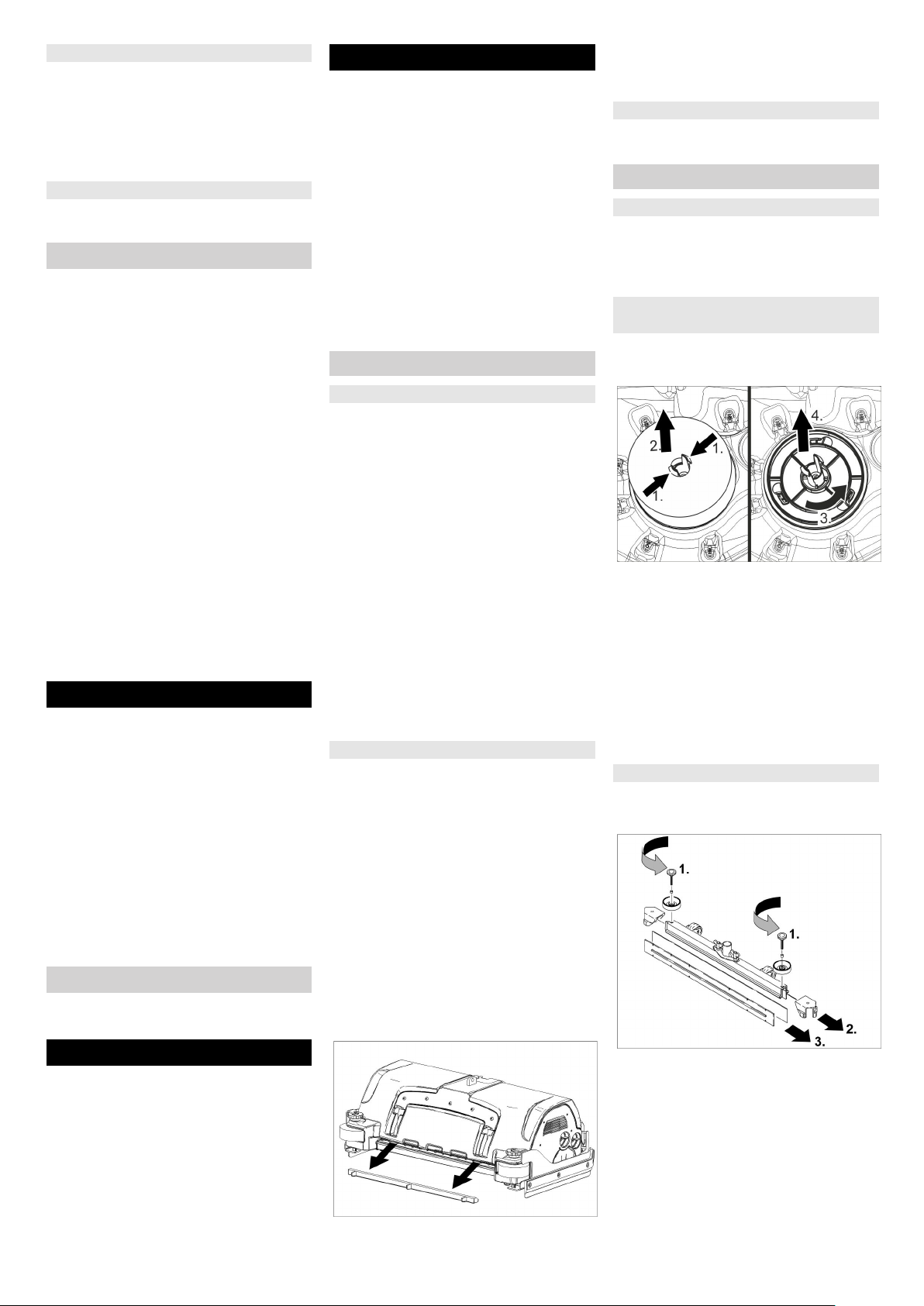
Cleaning the protective turbine
strainer
Open the cover of the wastewater
reservoir.
Squeeze the locking hooks.
Pull off the float.
Turn the protective turbine strainer
in a counter-clockwise direction.
Remove protective turbine strainer.
Rinse dirt off the protective turbine
strainer with water.
Reattach protective turbine strain-
er.
Attach float.
Replacing the vacuum lips
Remove the vacuum bar.
Unscrew the star grips.
Storage
CAUTION
Risk of injury and damage! Note the
weight of the appliance in case of storage.
This appliance must only be stored
in interior rooms.
Select the storage site for the appliance taking into consideration the permissible total weight of the appliance
in order not to impact its stability.
- 13
Remove the plastic parts.
Remove the vacuum lips.
Insert new vacuum lips.
Insert the plastic parts.
Screw in and tighten the star grips.
15EN
Page 16
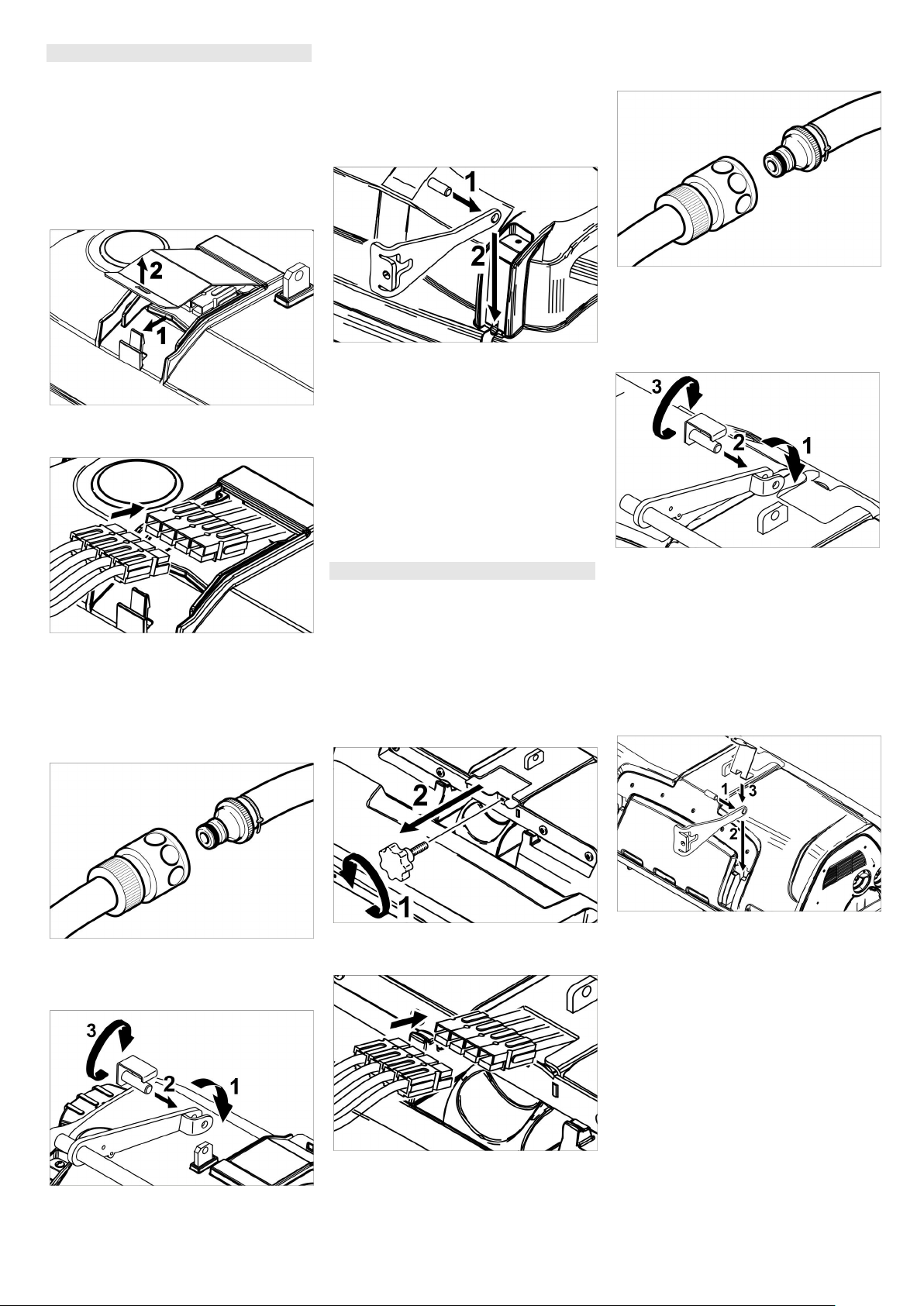
Install D cleaning head
Lift the holder of the cleaning head
(see Chapter "Grey intelligent key/
.../cleaning head replacement".
Slide the cleaning head under the
appliance so that the hose points
toward the rear.
Only slide the cleaning head halfway under the appliance.
Remove the lid of the cleaning
head.
Connect the power cord of the
cleaning head to the appliance
(same colours must meet).
Replace the lid and lock it.
Slide the cleaning head halfway un-
der the appliance.
Align the holder of the cleaning
head so that the drilled holes in the
lever and the cleaning head match.
Insert the stop pin through the
bushings and swivel the locking
plate downward.
Insert the cylinder pin into the bor-
ing of the drawbar.
Slide the drawbar with the pin the
guide channel on the cleaning head
all the way to the bottom.
Insert the locking plate into the
guide channel and lock it in.
Repeat process on the drawbar on
the opposite side.
Insert the grey intelligent key.
Set brush type "Disc".
Install R cleaning head
Lift the holder of the cleaning head
(see Chapter "Grey intelligent key/
.../cleaning head replacement".
Slide the cleaning head under the
appliance so that the hose points
toward the rear.
Only slide the cleaning head halfway under the appliance.
Slide the cleaning head halfway un-
der the appliance.
Connect the hose couplers on the
cleaning head to the hose on the
appliance.
Insert the tab into the middle of the
cleaning head, between the fork of
the lever.
Align the holder of the cleaning
head so that the drilled holes in the
lever and the cleaning head match.
Insert the stop pin through the
bushings and swivel the locking
plate downward.
Unscrew the star handle and re-
Connect the hose couplers on the
move the lid.
cleaning head to the hose on the
appliance.
Connect the power cord of the
cleaning head to the appliance
Insert the tab into the middle of the
cleaning head, between the fork of
(same colours must meet).
Slide the lid in and screw tight.
the lever.
16 EN
Insert the cylinder pin into the bor-
ing of the drawbar.
Slide the drawbar with the pin the
guide channel on the cleaning head
all the way to the bottom and lock.
Repeat process on the drawbar on
the opposite side.
Insert the grey intelligent key.
Set brush type "Brush".
- 14
Page 17
Remove D cleaning head
Press in the locking plate and swiv-
el the drawbar upward.
The subsequent removal will take
place in the opposite order of the installation.
Remove R cleaning head
The removal will take place in the opposite order of the installation.
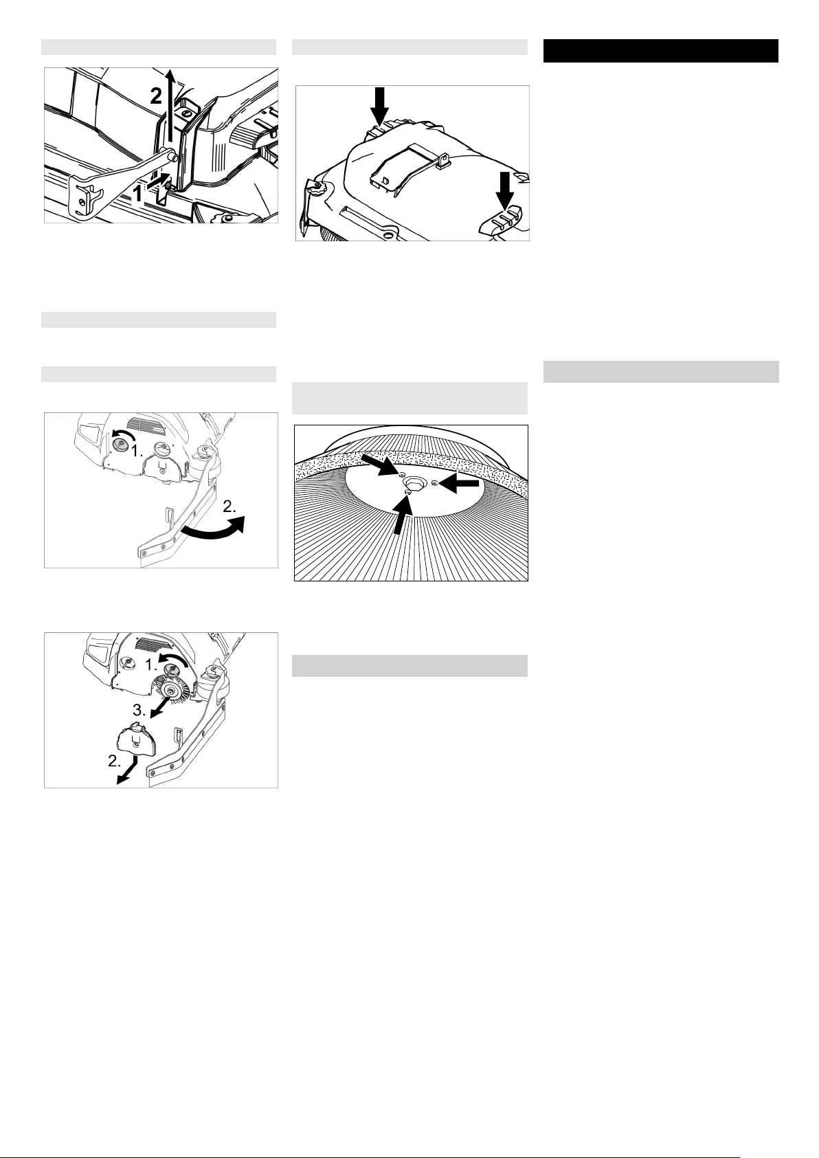
Replacing the brush rollers
Lift the cleaning head.
Loosen the lock of the wiper flap.
Swivel the wiping flap out of the
way.
Replacing the Disk Brushes
Lift the cleaning head.
Press the pedal for changing the
brushes downward beyond its resistance.
Pull the disc brush out of the side
below the cleaning head.
Hold the new disc brush under the
cleaning head, push upward and
lock.
Replacing the side brush (only with
SB version)
Loosen 3 screws.
Remove the wiper blade.
Push in the new side brush.
Tighten 3 screws.
Frost protection
In case of danger of frost:
Empty the fresh and dirt water res-
ervoirs.
Store the appliance in a frost-pro-
tected room.
Troubleshooting
DANGER
Risk of injury! Before working on the
appliance, remove the Intelligent Key
and the mains plug of the charger.
Pull out the battery plug.
Drain and dispose of the dirt water
and the residual fresh water.
CAUTION
Risk of injury due to overrun of the suction turbine.
Suction turbine will continue to run for
a while after switch-off. Carry out maintenance tasks only after the suction
turbine has come to a halt.
In case of faults that cannot be remedied using the table below please contact the customer service.
Fault indication
If errors appear on the display, then
proceed as follows:
Turn the program selection switch
to "OFF".
Wait till the text on the display has
disappeared.
Turn the programme switch into the
previous position.
Only carry out the troubleshooting
measures in the indicated order if
the error occurs again. The key
switch must be in the "0" position
and the emergency stop button
pressed.
If the fault cannot be repaired, call
customer service and mention the
error message.
NOTICE
Error messages that are not listed in
the following table, point to errors that
cannot be fixed by the operator. If
these are displayed, consult Customer
Service.
Loosen the lock of the wiper flap.
Push the bearing lid down and re-
move.
Pull out the brush roller.
Insert a new brush roller.
Reattach the bearing lid and the
wiper flap in reverse sequence.
Repeat process on the opposite
side.
- 15
17EN
Page 18

Faults with display
Display Cause Remedy
Seat switch open! Seat contact switch has not
Release the drive pedal. Have a seat.
been activated.
Release accelerator!
No direction of
travel!
Battery dis-
The gas pedal is depressed
Release drive pedal and reactivate.
when the main switch is on.
Travel direction switch or cable
Call customer service.
connection defective.
Battery voltage too low. Charge battery.
charged!
Battery voltage inadmissible!
Charger defective! Error on the charger, charging
Battery voltage is above or below the admissible range.
Call customer service.
Check the charger.
is not possible.
Fresh water tank
The fresh water tank is empty. Fill up fresh water reservoir.
empty!
Brush pressure not
reached!
Waste water tank
full!
Timeout brush contact pressure control.
Check brush wear, replace brush if required.
Check the function of the brush heads: lowering, raising.
wastewater reservoir is full. Empty the dirt water reservoir.
Level sensor or cable connec-
Call customer service.
tion defective.
Brake defective! Brake defective. Do not drive the appliance.
Call customer service.
Propulsion motor
hot! Allow to cool
down!
Motor protection was triggered Bring the safety switch into the "0" position.
Allow machine to cool down at least for 15 minutes.
Contact aftersales service in case of recurrence.
Horn defective! Horn defective. Call customer service.
Control is hot! Allow to cool down!
Brush motors overloaded!
Performance electronics of lift
module (A4) too hot
Load of the brush heads asymmetric.
Bring the safety switch into the "0" position.
Allow control to cool down at least 5 minutes.
Significantly reduce the brush pressure with rough ground.
Contact aftersales service in case of recurrence.
Adjust brush level.
18 EN
- 16
Page 19

Faults without display on the console
Fault Remedy
Appliance cannot be start-edSeat switch not operated, sit down on the seat.
The machine operates only if the operator is seated on the seat.
Bring the safety switch into the "1" position.
Set the programme switch to "OFF". Wait for 10 seconds. Set the programme selector
switch to previous function. If possible, drive the appliance on level grounds only. Check
parking brake and foot brake if necessary.
Take the foot off the accelerator pedal prior to switching on the safety switch. If the fault recurs, call the aftersales service.
Check battery; charge it, if needed
Insufficient water quantity Check fresh water level, refill tank if necessary.
Check hoses for blockages; clean if required.
R cleaning head: Remove the water distributor strip and clean it.
Clean the fresh water filter.
Insufficient vacuum performance
Insufficient cleaning result Set/ adjust contact pressure.
Brushes do not turn Reduce contact pressure.
Drain hose for dirty water is
blocked
Clean the seals between dirt water reservoir and cover and check for tightness, replace if
required.
Check protective turbine strainer for soiling, clean if necessary.
Clean the vacuum lips on the vacuum bar, turn or replace if required
Check if the cover on the dirt water discharge hose is closed
Check suction hose for blockages; clean if required.
Check the suction hose for tightness; replace if required.
Check the setting of the vacuum bar.
Attach additional weight (accessory) to the vacuum bar.
Adjust wiper lips.
Check the brushes for wear, replace if required.
Check if foreign matters block the brushes; remove foreign matter if required.
Motor overloaded, allow to cool down. Set the programme switch to "OFF". Wait for 10 seconds. Set the programme selector switch to previous function.
Open dosing equipment at the drain hose. Pull out the suction hose from suction beam and
close it by hand. Set the program selection switch to suction or vacuuming. The blockage
will be sucked out from the drain hose into the dirt water tank.
Detergent metering Dose
(only Dose) does not function properly
Inform Customer Service.
- 17
19EN
Page 20

Technical specifications
B 150 R 75 D 75 R 90 D90
Power
Nominal voltage V 36
Battery capacity Ah
(5h)
Average power consumption W 2700 2400 2800 2500
Nominal power engine (Adv) W 600 (1400)
Suction engine output W 750
Brush engine output W 2 x 600 2 x 750 2 x 600
Vacuuming
Cleaning power, air quantity l/s 26
Cleaning power, negative pressure kPa 18,0
Cleaning brushes
Working width mm 750 900
Brush diameter mm 105 410 105 450
Brush speed 1/min 1200 140 1200 140
Dimensions and weights
Driving speed, max. (Adv) km/h 6 (10)
Slope max. (Adv) % 10 (15)
Theoretical surface capacity (Adv) m2/h 4500 (7500) 5400 (10000)
Fresh/dirt water reservoir volume l 150
Capacity coarse dirt container l 7 - 9 -
Water pressure filling system**, waste water tank rinsing system**,
max.
MPa
(bar)
Length mm 1690
Width (without vacuum bar) mm 810 810 910 980
Height mm 1390
Permissible overall weight (Adv) kg 820 (838)
Transport weight (Adv) kg 586 (604)
Surface load (with driver and full fresh water tank)
Front wheel N/cm
Rear wheel N/cm
2
2
Values determined as per EN 60335-2-72
Vibration total value on arms m/s
Vibration total value on seat area m/s
Uncertainty K m/s
Sound pressure level L
Uncertainty K
pA
Sound power level LWA + Uncertainty K
pA
WA
2
2
2
dB(A) 67
dB(A) 2
dB(A) 85
** option
180/240
1 (10)
94
51
<2,5
<2,5
0,1
20 EN
- 18
Page 21

Accessories and Spare Parts
– Only use accessories and spare
parts which have been approved by
the manufacturer. The exclusive
use of original accessories and
original spare parts ensures that
the appliance can be operated
safely and trouble free.
– At the end of the operating instruc-
tions you will find a selected list of
spare parts that are often required.
– For additional information about
spare parts, please go to the Service section at www.kaercher.com.
Warranty
The warranty terms published by the
relevant sales company are applicable
in each country. We will repair potential
failures of your appliance within the
warranty period free of charge, provided that such failure is caused by faulty
material or defects in manufacturing. In
the event of a warranty claim please
contact your dealer or the nearest authorized Customer Service centre.
Please submit the proof of purchase.
- 19
21EN
Page 22

REMARQUE :
Cet appareil est conforme à la
section 15 des réglementations de la
FCC et aux normes RSS exemptes
de licence d'Industrie Canada.
Le fonctionnement est sujet aux deux
conditions suivantes :
(1) cet appareil ne doit pas provoquer d'interférences néfastes, et
(2) cet appareil doit tolérer les interférences reçues, y compris celles qui
risquent de provoquer un fonctionnement indésirable.
REMARQUE :
Tout changement ou toute modification apporté à cet équipement qui ne
serait pas expressément approuvé
par Kärcher pourrait annuler l'autorisation de la FCC d'exploiter cet équipement.
REMARQUE : Cet appareil a été testé et déclaré conforme aux limites relatives aux dispositifs numériques de
classe B, conformément à la
section 15 des réglementations de la
FCC. Ces limites sont destinées à assurer un niveau de protection adéquat contre les interférences dans les
installations résidentielles. Cet équipement produit, utilise et peut
émettre des fréquences radioélectriques et, s’il n’est pas installé ou utilisé conformément aux directives,
peut brouiller les ondes radio. Toutefois, il est impossible de garantir
qu'aucune interférence ne se produira dans une installation particulière.
Si cet équipement brouille la réception des ondes radio et télévision, ce
que vous pouvez déterminer en éteignant et en rallumant l’appareil, nous
vous encourageons à prendre l’une
ou plusieurs des mesures correctives
suivantes :
• Réorienter ou déplacer l’antenne de
réception.
• Augmenter l’écart entre l’équipement et le récepteur.
• Connecter l’équipement à une prise
ou à un circuit électrique différent de
celui auquel est branché le récepteur.
• Consultez votre revendeur ou un
technicien radio/télé expérimenté si
vous avez besoin d'aide.
CONSIGNES DE SÉCURITÉ
IMPORTANTES
Lire toutes les instructions de service
avant d'utiliser l'appareil.
몇 AVERTISSEMENT
Afin de réduire les risques d'incendie,
d'électrocution et de blessures,
prendre les précautions suivantes :
1 Ne pas laisser l'appareil sans sur-
veillance lorsqu'il est branché. Débrancher l'appareil lorsqu'il n'est
pas utilisé et avant de procéder à
l'entretien.
2 Utiliser l'appareil exclusivement en
intérieur pour réduire les risques
d'électrocution.
3 Cet appareil n'est pas un jouet. Ne
jamais le laisser sans surveillance
lorsqu'il est utilisé à proximité d'enfants.
4 Respecter impérativement les
consignes d'utilisation de ce manuel.
Utiliser uniquement les accessoires
recommandés par le fabricant.
5 Ne pas mettre l'appareil en service
en cas d'endommagement du cordon ou de la prise. Si l'appareil ne
fonctionne pas correctement, s'il
est tombé, s’il a été endommagé,
s’il est resté à l’extérieur ou est tombé dans l’eau, le retourner à un
centre de service.
6 Ne pas tirer ou transporter l’appa-
reil par le cordon électrique ou se
servir de ce dernier comme d’une
poignée. Veiller à ne pas coincer le
cordon dans une porte et éviter de
le tirer sur des bords ou des coins
tranchants. Ne pas rouler sur le cordon électrique. Tenir le cordon à
l'écart des surfaces chaudes.
7 Ne pas tirer sur le cordon électrique
pour débrancher l'appareil. Tirer au
niveau de la fiche pour déconnecter
l'appareil du secteur.
8 Ne pas manipuler l’appareil ou la
fiche avec les mains mouillées.
9 Ne rien introduire dans les orifices.
Ne pas utiliser l’appareil si l’un des
orifices est obstrué. Protéger les
orifices de la poussière, des peluches, des cheveux et autres matières susceptibles de réduire le
débit d'air.
10
Veiller à ne pas approcher les cheveux, vêtements larges, doigts ou
toute autre partie du corps des orifices
et composants mobiles de l’appareil.
11 Désactiver toutes les commandes
avant de débrancher l'appareil.
12 Faire particulièrement attention lors
du nettoyage d'escaliers.
13 Ne pas aspirer de liquides inflam-
mables ou combustibles, tels que
de l’essence avec l'appareil. Ne pas
utiliser ce dernier dans des zones
susceptibles de contenir de tels
produits.
14 Brancher uniquement sur une prise
correctement reliée à la terre. Voir
les instructions de mise à terre.
CONSERVER CES INSTRUCTIONS !
Instructions de mise à terre
Ce produit doit-être mis à la terre. En
cas de mauvais fonctionnement ou de
panne, la mise à la terre établit un chemin de moindre résistance pour le courant électrique afin de réduire le risque
de décharge électrique. Ce produit est
équipé d'un cordon doté d'un conducteur de mise à la terre de l'équipement
et d'une prise de mise à la terre. La
prise doit être branchée dans une prise
appropriée qui est correctement installée et mise à la terre en conformité
avec les codes et ordonnances locaux.
DANGER
Un conducteur de mise à la terre
d'équipement incorrectement branché
peut entraîner un risque d'électrocution. Vérifier avec un électricien ou un
technicien d'entretien qualifié en cas
de doute sur la mise à terre correcte de
la prise. Ne pas modifier la fiche fournie avec le produit - si elle ne peut pas
être branchée, faire installer une prise
appropriée par un électricien qualifié.
N'utiliser aucun type d'adaptateur avec
ce produit.
Cet appareil a été conçu pour fonctionner à une tension nominale de 120
volts ; sa fiche de mise à la terre est similaire à celle illustrée à la figure A.
S’assurer que la prise de courant utilisée est compatible avec la fiche secteur. Ne pas utiliser d'adaptateur pour
brancher cet appareil.
BRANCHER UNIQUEMENT SUR
UNE PRISE CORRECTEMENT RELIEE A LA TERRE
1 Prise reliée à la terre
2 Socle de prise de courant
3 Fiche de mise à terre
22 FR
- 1
Page 23

QUALIFICATION DES UTILI-
SATEURS
Seules les personnes formées et habilitées sont autorisées à utiliser les autolaveuses motorisées. Les utilisateurs
de ces appareils doivent avoir les aptitudes visuelles et auditives ainsi que
les capacités physiques et mentales
requises pour utiliser cet équipement
en toute sécurité.
FORMATION DES UTILISA-
TEURS
Les personnes n'ayant pas été formés
à l'utilisation des autolaveuses motorisées sont autorisées à se servir de ce
type d'appareil uniquement dans le
cadre de formations, et ce sous la surveillance d'un formateur. En outre, les
formations doivent être effectuées
dans des zones exemptes de tout obstacle, d'autres véhicules et de piétons.
Le programme de formation doit comprendre l'apprentissage du règlement
et des conditions d'utilisation propres
au site dans lequel les utilisateurs feront usage de l'autolaveuse ainsi
qu'une initiation à l'emploi du modèle
particulier d'autolaveuse qui sera utilisé. Le programme de formation sera
proposé à tous les nouveaux utilisateurs, quelle que soit leur expérience
antérieure.
Au cours de la formation, le stagiaire
sera informé des points suivants :
A Sa responsabilité principale est
d'utiliser l'autolaveuse motorisée en
toute sécurité, en respectant les
instructions prescrites dans le
cadre du programme de formation.
B L'utilisation incorrecte d'une autola-
veuse motorisée et le non-respect
des mesures de sécurité peuvent
provoquer : une mise en danger de
l'utilisateur ou de tiers (blessures
graves voire mortelles) ; l'endommagement de l'autolaveuse ou
d'autres dégâts matériels.
Le programme de formation portera
essentiellement sur l'utilisation correcte et en toute sécurité de l'appareil
afin d'éviter toute blessure de l'utilisateur ou d'un tiers et de prévenir les dégâts matériels. Elle abordera en outre
les aspects suivants :
A Caractéristiques principales de
l'autolaveuse ou des autolaveuses motorisées que le stagiaire utilisera :
1 caractéristiques de l'autolaveuse
ou des autolaveuses motorisées, y
compris les différences entre les
autolaveuses motorisées employées sur le lieu de travail ;
2 similitudes et différences avec les
automobiles ;
3 signification des données de
plaque signalétique, des mises en
garde et des instructions apposées
sur l'autolaveuse motorisée ;
4 consignes d'utilisation et mises en
garde du manuel d'utilisation de
l'autolaveuse motorisée et instructions relatives aux contrôles et opérations d'entretien incombant à
l'utilisateur ;
5 type de force motrice et ses
caractéristiques ;
6 méthode de conduite ;
7 méthode de freinage et ses
caractéristiques ;
8 visibilité avant et arrière ;
9 caractéristiques de stabilité avec et
sans chargement ainsi qu'avec et
sans accessoires ;
10 emplacement des commandes,
fonctions, instructions d'utilisation,
identification des symboles ;
11 chargement de la batterie ;
12 carters et dispositifs de protection
pour le type correspondant d'auto-
laveuse motorisée ;
13 autres caractéristiques du modèle
particulier d'autolaveuse motorisée.
B Environnement d'utilisation et son
influence sur le fonctionnement de
l'autolaveuse motorisée :
1 nature et état du sol ou du terrain, y
compris les conditions
temporaires ;
2 rampes et pentes ;
3 dispositif de chargement de la
batterie ;
4 allées étroites, portes, câbles aé-
riens, tuyauterie et autres zones dif-
ficiles d'accès ;
5 zones dans lesquelles il est pos-
sible d'utiliser l'autolaveuse motori-
sée à proximité d'autres machines
industrielles, véhicules ou piétons ;
6 utilisation et capacité des
élévateurs ;
7 utilisation à proximité d'un bord de
quai ou d'un terrain viabilisé ;
8 d'autres conditions d'utilisation et
risques peuvent se présenter.
C Utilisation de l'autolaveuse motori-
sée, notamment :
1 contrôle minutieux avant la prise de
poste et méthode appropriée pour
la mise hors service d'une autola-
veuse motorisée nécessitant des
réparations ;
2 déplacement de l'appareil, virages ;
3 procédures relatives au stationne-
ment et à l'arrêt ;
4 autres conditions d'utilisation parti-
culières pour l'application spécifique.
D Règles de sécurité et pratiques relatives à l'utilisation, notamment :
1 dispositions relatives aux normes
décrites dans la section « Règles
de sécurité et pratiques relatives à
l'utilisation » ;
2 autres règles, réglementations ou
pratiques précisées par l'employeur
pour l'endroit où l'autolaveuse motorisée sera utilisée.
E Exercices pratiques d'utilisation,
notamment :
1 si possible, une utilisation pratique
des autolaveuses motorisées doit
être effectuée dans une zone éloignée du personnel et de toute autre
activité exercée sur le lieu de
travail ;
2 cet exercice pratique sera réalisé
sous la surveillance du formateur ;
3 il consistera en l'utilisation concrète
de l'appareil ou en des simulations
de toutes les tâches telles que les
manœuvres, le déplacement, l'arrêt, le démarrage et autres commandes réalisées dans des
conditions similaires à celles qui seront rencontrées lors de l'utilisation
de l'autolaveuse motorisée.
TESTS, FORMATION DE RECLASSEMENT ET APPLICA-
TION
A Au cours de la formation, des tests
pratiques et tests écrits et/ou oraux
seront proposés par l'employeur
pour évaluer les compétences et
les connaissances du stagiaire et
s'assurer qu'elles répondent aux
exigences des normes. Les employeurs pourront déléguer ces
tests à d'autres membres du personnel. Cependant ils en seront
toujours responsables. Des archives pertinentes seront tenues.
B Les utilisateurs devront suivre de
nouvelles formations en cas d'introduction de nouveaux équipements
ou de modifications des équipements existants, en cas de changement des conditions d'utilisation ou
si leurs performances ne se révèlent pas satisfaisantes.
C L'utilisateur est tenu pour respon-
sable du respect des précautions
de sécurité lors de l'utilisation de
l'autolaveuse motorisée, conformément aux exigences des normes.
REMARQUE : des informations sur les
formations des utilisateurs sont disponibles auprès de sources variées,
- 2
23FR
Page 24

comme les fabricants d'autolaveuses
motorisées, les organismes administratifs chargés de la sécurité des employés, les organisations
professionnelles d'utilisateurs de machines industrielles, des organisations
publiques et privées, ainsi que des
spécialistes en matière de sécurité.
REGLES DE SECURITE ET
PRATIQUES RELATIVES A
L'UTILISATION
Responsabilité de l'utilisateur
L'utilisateur est responsable de l'utilisation en toute sécurité de l'appareil.
L'utilisateur devra mettre en œuvre
des habitudes de travail fiables et être
conscient des facteurs pouvant représenter des risques afin de prévenir
toute mise en danger de sa propre personne, des tiers, de l'autolaveuse motorisée et de tout autre équipement.
Avant d'utiliser l'appareil, l'utilisateur
devra avoir acquis une connaissance
approfondie des fonctions et du fonctionnement de toutes les commandes
et de tous les instruments.
Avant d'utiliser l'appareil, l'utilisateur
devra avoir lu et s'être familiarisé avec
le manuel d'utilisation de l'appareil en
question. Il devra par ailleurs se
conformer aux règles de sécurité et
pratiques décrites dans les paragraphes suivants.
Avant d'utiliser quelque appareil que
ce soit, l'utilisateur doit être conscient
des éventuelles conditions d'utilisation
inhabituelles pouvant nécessiter des
précautions de sécurité supplémentaires ou la mise en œuvre d'instructions d'utilisation particulières.
Généralités
Avant d'utiliser
l'autolaveuse motorisée :
A se mettre en position de service ;
B régler les commandes de direction
en position neutre ;
C activer le frein ;
D mettre le commutateur sur ON.
Ne pas démarrer ou utiliser l'appareil,
ni aucune de ses fonctions ou accessoires, à partir d'un autre endroit que
celui réservé à l'utilisateur.
Garder les mains et les pieds à l'intérieur de l'espace réservé à l'utilisateur
ou, le cas échéant, dans le logement
de l'appareil prévu à cet effet.
Apprécier les limites de l'appareil et utiliser ce dernier en respectant les
règles de sécurité de manière à ne pas
blesser le personnel. Toujours protéger les piétons.
A Ne pas diriger l'autolaveuse motori-
sée vers une personne se tenant
devant un objet.
B S'assurer qu'aucun individu ne se
trouve dans la zone située à l'arrière de l'appareil avant de procéder à des manœuvres de
changement de direction.
C Etre particulièrement attentif dans
les croisements, à l'approche de
portes et à tout autre endroit où des
piétons risquent d'apparaître sur le
parcours de l'autolaveuse motorisée.
Ne jamais autoriser des passagers sur
les autolaveuses motorisées sauf lorsqu'un emplacement sécurisé a été prévu par le fabricant à cet effet.
Une autolaveuse motorisée est sous la
surveillance de l'utilisateur lorsque ce
dernier se trouve à moins de
7,6 mètres et que l'appareil ne quitte
pas son champ de vision.
Une autolaveuse motorisée est considérée comme abandonnée lorsque
l'utilisateur se trouve à plus de
7,6 mètres, même si l'appareil est toujours dans son champ de vision ou
lorsqu'il quitte son poste et que l'appareil n'est plus dans son champ de vision.
Avant de quitter le poste de
l'utilisateur :
A arrêter l'appareil ;
B régler les commandes de direction
en position neutre ;
C actionner le frein à main ;
D éteindre le moteur ou arrêter toutes
les commandes ;
E si l'appareil doit stationner sur une
pente, caler les roues.
Conserver une distance de sécurité
avec les bords des rampes, des platesformes et de toutes les autres surfaces
de travail du même type.
Lors du chargement et du déchargement des autolaveuses motorisées
dans des camions ou remorques, les
freins de ces derniers doivent être actionnés. En outre, installer des cales
de roue ou tout autre dispositif de blocage mécanique similaire afin de prévenir les déplacements involontaires
des camions ou des remorques.
Lors du chargement et du déchargement d'autolaveuses motorisées dans
des semi-remorques non tractées, des
supports peuvent s'avérer nécessaires
pour éviter tout renversement ou basculement sur les côtés.
Faire particulièrement attention à ne
pas entrer en contact avec des installations aériennes (dispositifs d'éclai-
rage, câbles, tuyaux, extincteurs
automatiques, etc.)
Signaler tout incident affectant des
membres du personnel, des bâtiments
ou du matériel au chef d'équipe ou
conformément aux instructions reçues.
Ne pas ajouter d''accessoires à l'appareil ni le modifier de quelque manière
que ce soit.
Ne pas stationner à un endroit où l'appareil risque d'entraver les issues de
secours, les cages d'escaliers ou les
équipements de lutte contre l’incendie.
Conduite
Respecter le code de la route, y compris les limites de vitesse des chantiers. Dans des conditions de
circulation normales, serrer à droite.
Maintenir une distance de sécurité
avec le véhicule qui précède, en fonction de la vitesse. Garder le contrôle de
l'appareil en toutes circonstances.
Céder la priorité aux piétons ainsi
qu'aux véhicules d'urgence comme les
ambulances et les camions de pompiers.
Ne pas dépasser de véhicule circulant
dans la même direction au niveau des
croisements, des angles morts ou tout
autre endroit dangereux.
Ralentir et actionner le ou les avertisseur(s) sonore(s) aux croisements ou
chaque fois que la visibilité est limitée.
Traverser les voies ferrées à angle
droit lorsque c'est possible. Ne pas garer l'appareil à moins de 1,8 m de la
voie ferrée ou du rail le plus proche.
Monter et descendre les côtes lentement et avec prudence. Si possible,
éviter de tourner et faire particulièrement attention en côte et sur les
rampes où il faut normalement se déplacer en ligne droite.
Veiller à conserver une vue bien dégagée du trajet à emprunter et être attentif à la circulation des autres véhicules,
aux déplacements des membres du
personnel, ainsi qu'aux espaces de dégagement.
Quelles que soient les conditions de
circulation, conserver une vitesse permettant d'arrêter l'appareil en toute sécurité.
Lors du démarrage et de l'arrêt, ainsi
que dans les virages et lors des changements de direction, effectuer les manœuvres sans à-coups afin de ne pas
renverser le chargement et/ou l'autolaveuse motorisée.
Ne jamais adopter de conduite dangereuse (cascades, acrobaties etc.)
Ralentir sur les sols mouillés et glissants.
24 FR
- 3
Page 25

Avant de déplacer l'appareil sur un
pont de chargement ou un pont de laison, s'assurer que celui-ci est correctement sécurisé. Avancer prudemment
et lentement sur le pont de chargement
ou pont de liaison. Ne jamais dépasser
la charge maximale autorisée.
Ne jamais conduire l'autolaveuse motorisée sur un élévateur, sauf autorisation expresse préalable. Dans ce cas,
approcher lentement de l'élévateur et
entrer tout droit lorsque celui-ci est arrêté à niveau. Ensuite, placer les commandes de l'appareil en position
neutre, couper le contact et serrer le
frein de stationnement. Il est préférable
que les membres du personnel éventuellement présents dans l'ascenseur
en sortent avant l'entrée ou la sortie de
l'autolaveuse motorisée.
Dans les virages, ralentir et adopter
une vitesse de sécurité adaptée à l'environnement d'utilisation. Les virages
doivent être abordés sans à-coups.
Sauf lors de manœuvres à vitesse très
réduite, tourner le volant de façon régulière et sans à-coups.
L'utilisation d'une autolaveuse motorisée nécessite des mesures de sécurité
particulières, décrites ci-dessous.
A L'utilisateur doit absolument ralentir
suffisamment avant de procéder à des
virages sous peine de renverser l'autolaveuse motorisée. Les phénomènes
suivants indiquent que la vitesse d'un
véhicule est trop élevée dans les
virages :
1 dérapages ;
2 basculement du véhicule ;
3 soulèvement des roues ;
4 nécessité de se retenir fermement
au volant afin de ne pas glisser du
siège.
B Le risque de renversement latéral
est accru dans les conditions suivantes
(individuelles ou combinées) :
1 conduite sur une surface non
plane ;
2 conduite à une vitesse trop élevée.
C Le risque de basculement vers
l'avant est accru dans les conditions
suivantes (individuelles ou
combinées) :
1 Si l'autolaveuse motorisée tombe
d'un pont de chargement ou d'une
rampe. Dans ce cas, l'utilisateur ne
doit pas quitter l'autolaveuse. Il doit
se cramponner fermement et s'éloi-
gner du point d'impact.
2 Lorsque l'environnement constitue
un danger important ou en cas de
conditions d'utilisation inhabi-
tuelles. L'utilisateur peut alors re-
courir à des mesures de sécurité
différentes ou supplémentaires et
respecter des instructions d'utilisation adaptées aux conditions particulières.
Entretien de l'appareil par l'utili-
sateur
Au début de chaque prise de poste et
avant chaque utilisation de l'autolaveuse motorisée, vérifier l'état de l'appareil, en inspectant tout
particulièrement les éléments
suivants :
A état des pneus
B sur les pneumatiques, vérifier la
pression de gonflage
C fonctionnement de l'avertisseur et
autres dispositifs de sécurité
D dispositifs d'éclairage
E batterie
F commandes
G systèmes d'élévation et de bascule-
ment
H chaînes et câbles
I interrupteurs de fin de course
J freins
K mécanisme de direction
L autres éléments ou dispositifs sup-
plémentaires, conformément aux
instructions de l'exploitant et/ou du
fabricant.
Si le véhicule a besoin d'être réparé ou
présente un risque quelconque, l'utilisateur doit le signaler immédiatement
à son responsable et ne pas utiliser
l'appareil avant résolution du problème.
Si, en cours d'utilisation, le véhicule
s'avère dangereux de quelque façon
que ce soit, signaler immédiatement le
problème au responsable concerné et
cesser l'utilisation de l'appareil avant
résolution du problème.
Ne pas effectuer de réparations ou réglages à moins d'y être expressément
autorisé.
Ne pas éclairer les batteries à l'aide
d'un flamme vive pour vérifier le niveau
d'électrolyte.
PROCEDURES D'ENTRETIEN
ET DE REMISE EN ETAT
L'utilisation de l'appareil peut devenir
dangereuse si l'entretien est négligé
ou si la remise en état ou les réglages
nécessaires ne sont pas effectués en
conformité avec les recommandations
du fabricant. Par conséquent, il est nécessaire de prévoir des ateliers de
maintenance, à l'intérieur ou l'extérieur
des bâtiments, avec du personnel dûment formé, ainsi que d'établir des procédures détaillées.
Il est possible d'obtenir des guides des
pièces détachées ainsi que des manuels d'entretien auprès du fabricant
de l'autolaveuse.
Dans certains cas rares, non traités
par ces manuels de référence, consulter directement le fabricant de l'autolaveuse motorisée.
La maintenance et l'inspection de l'appareil doivent être effectuées conformément aux procédures suivantes :
A Les intervalles prescrits pour la
maintenance, la lubrification et le
contrôle du système doivent être
respectés; se reporter aux instructions du fabricant.
B La maintenance, les réparations,
les réglages et l'inspection de l'appareil doivent être confiés exclusivement à des personnes formées
et habilitées et effectués conformément aux recommandations du fabricant.
Soulever l'autolaveuse motorisée de
manière stable et sécurisée lorsque
cela est nécessaire pour une réparation ou un contrôle. Le démontage de
composants, tels que les masses
d'équilibrage ou les montants, modifie
le centre de gravité et risque des créer
une instabilité de l'appareil.
Avant de procéder au contrôle ou à la
réparation d'une autolaveuse
motorisée :
A soulever les roues motrices du sol
et débrancher la batterie. Utiliser
des cales de roues ou autre procédé mécanique conçu pour assurer
l'immobilisation de véhicules ;
B bloquer le châssis avant toute inter-
vention sur celui-ci ;
C débrancher la batterie avant d'inter-
venir sur le système électrique ;
D brancher le connecteur du chargeur
exclusivement sur le connecteur de
la batterie et jamais sur celui de
l'appareil.
Le contrôle du fonctionnement de l'autolaveuse motorisée doit être effectué
dans une zone autorisée et sécurisée.
A Avant d'utiliser l'autolaveuse
motorisée :
1 se mettre en position de service ;
2 activer le frein ;
3 régler les commandes de direction
en position neutre ;
4 mettre le commutateur sur ON ;
5 contrôler le fonctionnement des
systèmes d'élévation et de bascule-
ment, la direction, l'avertisseur so-
nore et les freins.
B Avant de quitter l'autolaveuse
motorisée :
1 arrêter l'appareil ;
- 4
25FR
Page 26

2 régler les commandes de direction
en position neutre ;
3 actionner le frein à main ;
4 couper le moteur ou mettre l'appa-
reil hors tension ;
5 arrêter le circuit de commande ;
6 si l'appareil doit stationner sur une
pente, caler les roues.
Eviter les risques d'incendie et s'assu-
rer que les locaux sont dotés des équipements nécessaires pour la lutte
contre l'incendie. Ne jamais éclairer les
batteries à l'aide d'une flamme vive
pour vérifier le niveau des liquides, en
particulier celui de l'électrolyte. Ne jamais utiliser de bacs ouverts contenant
du carburant ou des produits de nettoyage inflammables pour nettoyer les
composants de l'autolaveuse motorisée.
Ventiler suffisamment la zone de travail, aérer pour évacuer les gaz
d'échappement et veiller à ce que l'atelier soit toujours propre et sec.
Inspecter régulièrement les freins, la
direction, les mécanismes de commande et de direction, les avertisseurs, les feux, les régulateurs, ainsi
que les dispositifs de protection et de
sécurité et les maintenir en parfait état
de marche pour qu’ils puisent être utilisés sans danger.
NORMES DE SECURITE IN-
CENDIE
Tout appareil dont le fonctionnement
représente un risque doit être mis hors
service.
Les réparations ne doivent pas être effectuées dans les zones de classe I, II
et III.
La batterie doit être débranchée avant
toute réparation sur le système électrique d'une autolaveuse.
Température de service : si la température d'un composant de l'autolaveuse motorisée dépasse la
température de service normale et, par
conséquent, devient source de danger, le véhicule doit être mis hors service et ne pas être réutilisé tant que la
source de surchauffe n'a pas été réparée.
Prévention des incendies : L'autolaveuse motorisée doit être tenue propre
et dans la mesure du possible, protégée des peluches, des déversements
d'huile et de la graisse. L'utilisation de
produits non inflammables est recommandée pour le nettoyage de l'autolaveuse motorisée. Les liquides
inflammables dont le point d'ignition
est égal ou supérieur à 37,8 °C
(100 °F) ne sont pas autorisés.
Prendre les mesures appropriées
concernant la toxicité, l'aération, et les
risques d'incendie selon le produit ou
solvant utilisé.
Visibilité de la plaque signalétique :
Les données techniques figurant sur la
plaque signalétique de l'appareil ne
doivent pas être recouvertes de peinture et les informations d'identification
doivent rester visibles.
Remplacement et chargement des
batteries :
Cette section concerne les batteries
utilisées sur des véhicules électriques.
Les deux types de batteries généralement utilisées sont les batteries au
plomb et les batteries au ferro-nickel.
Elles contiennent des composants
chimiques corrosifs (acide ou alcalin)
et représentent donc un risque
chimique. Lors du chargement, les batteries dégagent de l'hydrogène et de
l'oxygène qui, dans certaines conditions, peuvent se combiner pour former un mélange explosif.
Le chargement des batteries doit être
effectué dans des endroits désignés à
cet effet, où aucune matière combustible ne doit être stockée. Des équipements doivent être prévus pour :
A rincer les déversements
d'électrolyte ;
B lutter contre l'incendie ;
C protéger le matériel de chargement
des endommagements par des vé-
hicules et
D pour assurer une ventilation suffi-
sante afin d'évacuer les fumées
produites par les batteries à es-
sence.
Lorsque des chargeurs embarqués
sont utilisés, le chargement doit être
effectué dans des endroits prévus à
cet effet, en fonction des exigences
électriques du chargeur et des équipements pour la lutte contre l'incendie.
Exception : Les produits de rinçage ne
sont pas nécessaires si le chargement
est effectué sans retirer la batterie du
véhicule.
Lors de la manipulation de concentrations d'acide supérieures à 50 % (densité au-delà de 1 400), une douche
oculaire est indispensable.
Un transporteur, un palan suspendu ou
autre équipement de manutention doit
être prévu pour la manipulation des
batteries.
Les appareils de levage à chaîne
doivent être équipés de chaînes de levage. Lorsque des appareils de levage
manuels sont utilisés, les batteries ouvertes doivent être recouvertes d'une
feuille de contreplaqué ou autre maté-
riau non conducteur afin d'éviter les
courts-circuits de la chaîne de manœuvre au niveau des pontets de
connexion ou des bornes. Un palonnier correctement isolé doit être utilisé
avec les palans suspendus.
La capacité des batteries rechargées
ou batteries neuves doit être égale ou
supérieure à celle indiquée sur l'appareil. Installer les batteries rechargées
correctement dans l'appareil.
Un vide-tourie ou un siphon devra être
prévu dans les locaux où de l'acide en
touries est utilisé. Lors de la dilution
d'acide sulfurique concentré pour obtenir de l'électrolyte, l'acide doit TOUJOURS être ajouté à l'eau et non
l'inverse. Les membres du personnel
procédant à l'entretien des batteries
doivent porter des vêtements de protection, tels que des verres protecteurs, des manches longues et des
gants.
Exception : Le démontage et le remplacement des batteries ne nécessite
pas l'utilisation de vêtements de protection.
Les installations électriques doivent
être conformes au NFPA 70 (code national électrique américain) ainsi
qu'aux règlements locaux.
Seules les personnes compétentes et
habilitées sont autorisées à procéder
au démontage et au chargement des
batteries.
L'autolaveuse motorisée doit être en
position adéquate et les freins doivent
être actionnés avant toute tentative de
remplacement ou de chargement des
batteries.
Lors du chargement des batteries, le
capuchon d'évacuation doit rester en
place de façon à éviter toute projection
d'électrolyte. Prendre soin de vérifier
que les capuchons d'évacuation fonctionnent. Les caches (ou le compartiment) de batterie doivent être ouverts
pour dissiper la chaleur et le gaz.
Il est interdit de fumer dans la zone dédiée au chargement de la batterie.
Les mesures nécessaires doivent être
prises pour éviter les flammes vives,
les étincelles et les arcs électriques
dans les zones de chargement des
batteries.
Ne jamais poser des outils ou autres
objets mécaniques sur des batteries
ouvertes.
L'autolaveuse motorisée ne doit pas
être utilisée dans les zones classées.
26 FR
- 5
Page 27

Lire ce manuel d'utilisation
original avant la première utilisation de votre appareil, le respecter
et le conserver pour une utilisation ultérieure ou pour le futur propriétaire.
Table des matières
Consignes de sécurité . . . . FR . . 6
Fonction . . . . . . . . . . . . . . . FR . . 6
Utilisation conforme . . . . . . FR . . 6
Protection de l’environnement FR . . 6
Eléments de commande . . . FR . . 7
Avant la mise en service. . . FR . . 8
Fonctionnement . . . . . . . . . FR . 10
Intelligent Key grise . . . . . . FR . 12
Transport. . . . . . . . . . . . . . . FR . 13
Entreposage . . . . . . . . . . . . FR . 13
Entretien et maintenance . . FR . 13
Assistance en cas de panne FR . 16
Caractéristiques techniques FR . 18
Accessoires et pièces de re-
change . . . . . . . . . . . . . . . . FR . 19
Garantie . . . . . . . . . . . . . . . FR . 19
Consignes de sécurité
Lire la présente notice d'instructions
ainsi que la brochure ci-jointe
"Consignes de sécurité pour les autolaveuses à brosses et les injecteursextracteurs " n° 5.956-251 avant d'utiliser l'appareil pour la première fois et
respecter les instructions.
L'appareil n'est autorisé au fonctionnement que sur des surfaces ayant la
pente maximale indiquée dans la section « Données techniques ».
Dispositifs de sécurité
Les dispositifs de sécurité ont pour but
de protéger l'utilisateur et ils ne doivent
donc jamais être désactivés ni évités.
Coupe-circuit
Pour une mise hors service immédiate
de toutes les fonctions : Mettre le commutateur de sécurité en position '0'.
– En cas de désactivation du couper,
éteindre, mettre hors circuit, désactiver, l'appareil freine brusquement.
– La touche d'arrêt d'urgence désac-
tive immédiatement toutes les fonctions de l'appareil.
Contacteur de siège
Met le moteur de traction hors service
après une brève temporisation quand
l'exploitant quitte le siège pendant le
fonctionnement de travail ou en circulation.
Des symboles sur l'appareil
PRÉCAUTION
Risque de blessure causée par l'écrasement.
Éloigner les mains de
cette zone lors de l'abaissement du bac d'eau sale.
DANGER
Fort risque d'accident en
raison d'une vitesse élevée. Conduire lentement
sur des pentes.
Niveaux de danger
DANGER
Pour un danger immédiat qui peut
avoir pour conséquence la mort ou des
blessures corporelles graves.
몇 AVERTISSEMENT
Pour une situation potentiellement
dangereuse qui peut avoir pour conséquence des blessures corporelles
graves ou la mort.
PRÉCAUTION
Remarque relative à une situation potentiellement dangereuse pouvant entraîner des blessures légères.
ATTENTION
Remarque relative à une situation
éventuellement dangereuse pouvant
entraîner des dommages matériels.
Fonction
L’aspirateur à abrasion sert au nettoyage humide ou au polissage de sols
plans.
Il est facile d’adapter l'appareil à la
tâche de nettoyage à accomplir en réglant la quantité d’eau, la pression des
brosses, la quantité de détergent ainsi
que la vitesse de transport.
Utilisation conforme
L'utilisation de l'appareil doit être faite
en conformité avec les consignes figurant dans les instructions de service.
– L'appareil doit uniquement être uti-
lisé pour nettoyer des surfaces
planes non sensibles à l'humidité ni
au polissage.
– Cet appareil est destiné à une utili-
sation dans les locaux intérieurs.
– La plage de température pour l'utili-
sation est de +5°C à +40°C.
– L'appareil n'est pas approprié pour
nettoyer des sols gelés (par
exemple dans des entrepôts frigorifiques)
– L'appareil convient à une hauteur
d'eau maximum de 1 cm. Ne pas
rouler dans une zone dans laquelle
la hauteur d'eau maximum risque
d'être dépassée.
– L'appareil doit uniquement être
équipé d'accessoires et de pièces
de rechange d'origine.
– L'appareil n'est pas destiné au net-
toyage de voies publiques.
– L'appareil ne peut être utilisé sur
des sols qui sont sensibles à la
pression. Tenir compte de la sollicitation concentrée admissible du
sol. La charge concentrée par l'appareil est indiquée dans les données techniques.
– L'appareil n'est pas approprié pour
l'application dans des environnements à risque d'explosion.
– Ne pas aspirer avec l'appareil des
gazes combustibles, acides ou solvants non dilués.
Ces-ci sont essence, dilutif de couleurs ou fuel, qui peuvent former
des mélanges explosives en touillant avec l'air d'aspiration. Ne pas
utiliser d’acétone, d’acides ou de
solvants non dilués, du fait de leur
effet corrosif sur les matériaux
constituant l’appareil.
Protection de l’environne-
ment
Les matériaux constitutifs
de l'emballage sont recyclables. Ne pas jeter les
emballages dans les ordures ménagères, mais les
rendre à un système de recyclage.
Les appareils usés
contiennent des matériaux
précieux recyclables lesquels doivent être rendus à
un système de recyclage.
Des batteries, de l’huile et
d'autres substances semblables ne doivent pas être
tout simplement jetées.
Pour cette raison, utiliser
des systèmes adéquats de
collecte pour éliminer les
appareils usés.
Instructions relatives aux ingrédients (REACH)
Les informations actuelles relatives
aux ingrédients se trouvent sous :
www.kaercher.com/REACH
- 6
27FR
Page 28

Eléments de commande
1 Pupitre de commande
2 Volant
3 feu de détresse **
4 Surface de dépose pour le kit de
nettoyage « Homebase Box »
5 Dispositif de dosage pour l'eau sale
6 raccord d'alimentation en eau pour
système de rinçage du bac d'eau
sale **
7 support de mopp **
8 système de rinçage du bac d'eau
sale **
9 Couvercle du réservoir d'eau sale
10 Flotteur
11 Crible à peluches
12 Réservoir d'eau sale
13 Porte-outil **
14 Flexible de vidange pour eau sale
15 Barre d'aspiration *
16 Levier de réglage du siège
17 Siège (avec contacteur de siège)
18 Système de remplissage **
19 Couvercle réservoir d'eau fraîche
20 Pédale de marche
21 balai latéral (uniquement variante
SB)
22 Roue de réglage lèvre d'enlève-
ment
23 Lèvre d'enlèvement
24 Tête de nettoyage *
25 Réglage en hauteur des suceurs
26 Ecrous-papillon pour fixer la barre
d'aspiration
28 FR
27 Poignée rotative pour incliner la
barre d'aspiration
28 Verrou, réservoir d'eau sale
29 Flexible d’aspiration
30 Bac à déchets (uniquement avec
tête de nettoyage R) *
31 Fermeture du réservoir d'eau
propre avec filtre pour eau du robi-
net
32 Batterie
* pas comprise dans l'étendue de livraison
** Option
- 7
Page 29

Pupitre de commande
5 Programme Heavy
Nettoyage humide du sol et aspiration de l'eau sale (avec une pression d'appui des brosses plus
élevée).
6 Frotter
Nettoyage humide du sol et laisser
agir le détergent.
7 Aspiration
Aspirer la saleté.
8 Polissage
Polir le sol sans appliquer de liquide.
Des symboles sur l'appareil
Toute flamme, matière incandescente, étincelle ou cigarette est interdite à proximité
de la batterie.
Risque de brûlure
Premiers soins
Attention
Mise au rebut
1 Coupe-circuit
2 Commutateur de programmes
3 Intelligent Key
4 Bouton Info
5 Ecran
6 Commutateur de sens de déplace-
ment
7 Avertisseur sonore
Commutateur de programmes
Poignée pour basculer vers
le haut le bac d'eau sale
Point d'arrimage
support de mopp **
Raccord d'alimentation en
eau du système de remplissage **
raccord d'alimentation en
eau pour système de rinçage du bac d'eau sale **
Ouverture de vidange du
réservoir d'eau propre
Ouverture de vidange du
bac d'eau sale
** Option
Avant la mise en service
Batteries
Ne pas mettre la batterie au
rebut dans le vide-ordures
DANGER
Risque d'explosion !
Ne pas poser d'outils ou d'objets similaires sur la batterie. Risque de courtcircuit et d'explosion.
Risque de blessure. Ne jamais mettre
en contact des plaies avec le plomb.
Prendre soin de toujours se laver les
mains après avoir manipulé la batterie.
Batteries recommandées
/h] **
3
flux d'air [m
Jeu de batteries 240Ah,
cuve, peu de
maintenance
Jeu de batteries 180Ah,
cuve, peu de
maintenance
N° de réf.
4.035-
987.7
4.035-
988.7
} *
3
Volume [m
27 10.8
20.25 8.1
1 OFF
Appareil hors circuit.
2 Déplacement de transport
Déplacer l'appareil vers le lieu d'utilisation.
3 Programme Eco
Nettoyage humide du sol (avec vitesse de brosse réduite) et aspiration d'eau sale (avec puissance
d'aspiration réduite).
4 Aspiration de récurage
Nettoyage humide du sol et aspiration de l'eau sale.
Respecter les consignes situées sur la batterie, dans les
instructions de service et dans
le mode d'emploi du véhicule
Porter des lunettes de protection
Tenir les enfants à l'écart des
acides et des batteries
Risque d'explosion
- 8
Jeu de batteries 240Ah, 6
4.654-
306.7
6,975 2.79
blocs, sans
entretien
Jeu de batteries 180Ah, 6
4.654-
307.7
5,175 2.07
blocs, sans
entretien
* Volume minimal de la station de
charge pour batteries
** flux minimal d'air entre la station de
charge pour batteries et l'environnement
29FR
Page 30

Montage et branchement des batteries
Mettre le commutateur de sécurité
en position '0'.
Pivoter le réservoir d'eau sale vers
l'arrière.
4.035-987.7
4.035-988.7
4.654-306.7 (disposition A)
4.654-307.7 (disposition A)
ATTENTION
Risque d'endommagement. Veiller à
respecter les polarités.
Graisser les bornes de batterie
avec graisse de borne.
Connecter les bornes avec le câble
de raccordement ci-joint.
Brancher le câble de raccordement
ci-joint aux bornes de batterie encore libres (+) et (-).
Brancher la fiche de batterie.
ATTENTION
Risque d'endommagement à la suite
d'un déchargement intégral. Charger
les batteries avant de mettre l'appareil
en service.
Charger les batteries
REMARQUE
L'appareil dispose d'une protection
anti-décharge complète, c'est-à-dire
qu'il développe encore la puissance
minimale autorisée de sorte que l'appareil puisse être uniquement déplacé.
À l'écran apparaît l'affichage « Batterie
faible - Nettoyage impossible » et
« Batterie vide - Veuillez la charger ».
Amener immédiatement l'appareil à
la station de charge en évitant les
pentes.
REMARQUE
En cas d'utilisation d'une autre batterie
(ex. : d'un autre fabricant), le dispositif
de protection anti-décharge complète
doit être de nouveau réglé par le service après-vente Kärcher et ce, pour
chaque batterie.
DANGER
Risque d'électrocution. Tenir compte
du réseau de conduction de courant et
de la protection par fusibles - voir
"Chargeur". Utiliser le chargeur seulement dans des pièces sèches et suffisamment aérée !
REMARQUE
Le temps de charge s'élève en
moyenne à environ 10-12 heures.
Les chargeurs recommandés (adaptables à toutes les batteries) disposent
d'une réglage électronique et mettent
fin automatiquement à la procédure de
charge.
DANGER
Risque d'explosion. La pièce dans laquelle l'appareil est garé pour que ses
batteries soient chargées doit avoir un
volume minimal qui est fonction du
type de batterie et un renouvellement
d'air avec un flux minimal d'air (cf.
« Batteries recommandées »).
Risque d'explosion. Le chargement
des batteries humides est seulement
permis avec réservoir d'eau sale basculé vers le haut.
Basculer le bac d'eau sale vers le
haut.
Séparer les connecteurs de batterie
et raccorder le câble de charge du
chargeur.
Brancher la fiche secteur du char-
geur.
Lancer le processus de charge-
ment conformément au mode d'emploi séparé du chargeur de batterie.
Batteries pour service à maintenance réduite (batteries humides)
Ajouter de l'eau distillée une heure
avant la fin de la procédure de
charge. Respecter le niveau d'aci-
dité approprié. Les mentions cor-
respondantes figurent sur la
batterie. A la fin du processus de
chargement, toutes les cellules
doivent être en formation de gaz.
DANGER
Risque de brûlure. L'appoint d'eau
dans une batterie déchargée pouvant
provoquer des fuites d'électrolyte,
porter impérativement des lunettes de
protection en manipulant l'acide de
batteries et respecter les consignes
afin d'éviter toute blessures et toute
destruction de vêtements.
Rincer immédiatement et à l'eau abondante l'électrolyte ayant giclé sur la
peau ou les vêtements.
ATTENTION
Pour remplir la batterie, utiliser uniquement de l'eau distillée ou dessalée (EN
50272-T3).
N'employer aucun additif (produit dit
d'amélioration) sous peine d'annulation de toute garantie.
Dimensions maximales de la batterie
Disposition
Longueur 244 mm 312 mm
Largeur 190 mm 182 mm
Hauteur 275 mm 365mm
Remarque relative au premier chargement
Lors du premier chargement, la commande ne détecte pas encore le type de
batterie installé. Chargez les batteries
jusqu'à ce que l'affichage Chargement
terminé apparaisse (il se peut que les
batteries ne soient pour autant pas totalement chargées). Lors du chargement
suivant, l'affichage et le courant de chargement sont alors exacts et les batteries
entièrement chargées.
Remarque :
Un « V » à côté de la barre de l'affichage de la batterie indique que le premier chargement n'est pas encore
effectué.
Utiliser l'appareil après le premier
chargement des batteries jusqu'à ce
que le dispositif anti-décharge totale
arrête le moteur de brosse et la turbine. Ce processus est nécessaire
pour ajuster l'affichage de la batterie.
Ce n'est qu'ensuite que le niveau de la
batterie correct sera affiché.
AB
30 FR
- 9
Page 31

Démonter les batteries
Mettre le commutateur de sécurité
en position '0'.
Pivoter le réservoir d'eau sale vers
l'arrière.
Débrancher le câble du pôle moins
de la batterie.
Déconnecter les câbles restants de
la batterie
Sortir les batteries.
Eliminer les batteries dans le res-
pect des dispositions en vigueur.
Déchargement de la machine
REMARQUE
Pour une mise hors service immédiate
de toutes les fonctions, mettre le commutateur de sécurité en position "0".
Quatre planches de fond de la pa-
lette sont vissées. Dévisser ces
planches.
Actionner l'accélérateur.
Faire descendre l'appareil de la pa-
lette.
Mettre le commutateur de sécurité
en position '0'.
Monter une tête de nettoyage
Le montage de la tête de nettoyage est
décrit dans le chapitre "Travaux d'entretien".
REMARQUE
La tête de nettoyage est déjà montée
sur certaines modèles.
Montage des brosses
Le montage des brosses est décrit
dans le chapitre "Travaux d'entretien".
Montage de la barre d'aspiration
Contrôler le frein d'immobilisa-
tion
DANGER
Risque d'accident. Avant toute mise en
service, il convient de vérifier le fonctionnement du frein d'immobilisation
sur une surface plane.
Mettre l’appareil sous tension.
Mettre le commutateur de sens de
marche sur "Avant".
Régler l'interrupteur de programme
sur marche transport.
Appuyer légèrement sur la pédale
d’accélérateur.
Le frein doit se déverrouiller de ma-
nière audible. Sur une surface
plane, l'appareil doit avancer légè-
rement. Lorsque la pédale est relâ-
chée, le frein se déclenche de
manière audible. Dans le cas
contraire, mettre l'appareil hors ser-
vice et contacter le service après-
vente.
Poser les planches sur le bord de la
palette. Orienter les planches de
manière à ce qu'elles reposent en
amont des roues de l'appareil. Fixer
les planches à l'aide des vis.
Pousser les barre de soutien conte-
nue dans l'emballage sous la
rampe.
Retirer les listeaux en bois figurant
devant les roues.
Tirer le levier de frein et faire des-
cendre l'appareil de la rampe avec
le levier tiré.
ou
Insérer l'Intelligent Key.
Mettre le commutateur de sécurité
en position '1'.
Régler l'interrupteur de programme
sur marche transport.
Mettre le commutateur de sens de
marche sur "Avant".
Poser les barres d'aspiration dans
la suspension de la barre d'aspiration que la tôle profilée se trouve
au-dessous de la suspension.
Serrer à fond les écrous-papillons.
Emmancher le flexible d'aspiration.
Fonctionnement
DANGER
Risque de blessure. Ne pas utiliser
l'appareil sans toit protecteur contre la
chute d'objets dans les endroits où il
est possible que l'utilisateur risque
d'être atteint par des objets chutant.
REMARQUE
Pour une mise hors service immédiate
de toutes les fonctions, mettre le commutateur de sécurité en position "0".
Réglage du siège du conducteur
Activer le levier de réglage du siège
et pousser le siège dans la position
souhaitée.
Relâcher le levier de réglage du
siège et enclencher le siège.
Mettre l'appareil en marche
Régler la position du siège.
Insérer l'Intelligent Key.
Mettre le commutateur de sécurité
en position '1'.
Tourner le sélecteur de programme
sur la fonction souhaitée.
Déplacement
DANGER
Risque d'accident. Si l'appareil ne développe plus aucun effet de freinage,
procéder comme suit :
Pour des raisons de sécurité, si
l'appareil ne s'immobilise pas sur
une rampe dont l'inclinaison est su-
périeur à 2 % lorsque la pédale
d'accélérateur est relâchée, mettre
le commutateur de sécurité en posi-
tion "0" que si le fonctionnement
mécanique du frein de stationne-
ment à préalablement été vérifié et
déclaré opérationnel à chaque mise
en service de l'appareil.
Lorsque l'appareil est à l'arrêt (sur
une surface plane), le mettre hors
service et contacter le service
après-vente !
De plus, respecter les consignes
d'entretien relatives aux freins.
DANGER
Risque de basculement en cas de
pente trop forte.
Conduire dans le sens de la
marche uniquement sur des pentes
jusqu'à 10 % (Adv 15 %).
Prendre des pentes et des surfaces
inclinées uniquement dans le sens
de la longueur ; ne pas tourner.
Risque de basculement en cas de
conduite rapide dans les virages.
Chaussée glissante en cas de sol humide.
Roulez lentement dans les virages.
Risque de basculement en cas de sol
instable.
- 10
31FR
Page 32

N'utilisez la machine que sur des
sols stabilisés.
Risque de basculement en cas de
pente latérale trop importante.
Déplacement
Régler la position du siège.
Insérer l'Intelligent Key.
Mettre le commutateur de sécurité
en position '1'.
Régler l'interrupteur de programme
sur marche transport.
Régler la sens de circulation avec
l'interrupteur de la sens de circulation à la pupitre de commande.
Déterminer la vitesse de marche en
actionnant la pédale de marche.
Immobiliser la machine: Lâcher la
pédale de marche.
REMARQUE
La sens de circulation peut être modifiée aussi pendant la circulation. En
avançant et reculant il est aussi possible de polir aussi des endroits très
ternes.
Surcharge
En cas de surcharge, le moteur de
traction est désactivé après une durée
définie. Un message signalant un défaut s'affiche à l'écran. En cas de surchauffe du système de commande, le
module concerné est désactivé.
Laisser refroidir l'appareil au moins
15 minutes.
Tourner le sélecteur de programme
sur "0", attendre brièvement puis le
positionner de nouveau sur le programme souhaité.
Remplissage de carburant
Produit détergent
ATTENTION
Risque d'endommagement. Utiliser
uniquement les détergents recommandés. Pour tout autre détergent, l'exploitant prend des risques plus élevés
quant à la sécurité du travail et au
risque d'accident.
N'utiliser que des détergents exempts
de solvants, d'acide chlorhydrique et
d'acide flurohydrique.
Respecter les consignes de sécurité figurant sur les détergents.
Remarque
Ne jamais utiliser de détergents extrêmement moussants.
Détergents recommandés :
Application Produit
détergent
Nettoyage d'entretien
de tous les sols résis-
RM 746
RM 780
tants à l'eau
Nettoyage d'entretien de
RM 755 es
surfaces brillantes (par
exemple du granite)
Nettoyage d'entretien et
nettoyage minutieux de
RM 69
ASF
sols dans le secteur industriel
Nettoyage d'entretien et
RM 753
nettoyage minutieux de
carrelages en grès cérame fin
Nettoyage d'entretien
RM 751
de carrelages dans le
secteur sanitaire
Nettoyage et désinfec-
RM 732
tion dans le secteur sanitaire
Enlèvement d'une
RM 752
couche sur tous les sols
résistants aux alcalis
(par exemple PVC)
Enlèvement d'une
RM 754
couche sur des sols en
linoléum
Eau propre
Ouvrir le couvercle du réservoir
d'eau propre.
Remplir eau propre (60 °C au maxi-
mum) jusqu'à 15 mm au-dessus du
limite supérieur du réservoir.
Remplir détergent.
REMARQUE
Mettre en premier du détergent puis de
l'eau dans le réservoir de détergent
peut provoquer une forte formation de
mousse.
Fermer le couvercle du réservoir
d'eau propre.
REMARQUE
Avant la première mise en service,
remplir complètement le réservoir
d'eau propre, pour purger la canalisation d'eau.
Système de remplissage (option).
Raccorder le flexible sur la tubulure
de raccordement du système de
remplissage.
Ouvrir l'alimentation d'eau.
Si le niveau de remplissage maximum est atteint, la valve à flotteur
intégrée coupe l'arrivée d'eau.
Couper l'alimentation en eau.
Enlever le flexible d'eau.
Réglage des paramètres
Avec Intelligent Key jaune
Les paramètres pour les divers programmes de nettoyage sont préréglés
dans l'appareil.
En fonction de l'autorisation de l'Intelligent Key jaune, des paramètres individuels peuvent être modifiés.
La modification des paramètres ne
reste effichage que jusqu'à ce qu'un
autre programme de nettoyage soit sélectionné à l'aide du sélecteur de programme.
Au cas où les paramètres devraient
être modifiés définitivement, une Intelligent Key grise doit être utilisée pour le
paramétrage. Le paramétrage est décrit au chapitre « Intelligent Key
grise ».
Remarque :
Presque tous les textes sur l'écran
pour le réglage des paramètres sont
auto-explicatifs. Le paramètre FACT
constitue l'exception confirmant la
règle :
– Fine Clean : Rotation faible de la
brosse pour éliminer voilage sur
grès cérame fin.
– Whisper Clean : Rotation moyenne
de la brosse pour le nettoyage d'entretien avec un niveau sonore réduit.
– Power Clean : Rotation élevée de la
brosse pour polir , cristalliser et balayer.
Tourner le sélecteur de programme
sur le programme de nettoyage
souhaité.
Tourner le bouron Info, jusqu'à ce
que le paramètre voulu soit affiché.
Appuyer sur le bouton Info - la va-
leur réglée clignote.
Régler la valeur voulue en tournant
le bouton Info.
Confirmer les modifications en ap-
puyant sur le bouton Info ou attendre 10 secondes afin que la
valeur paramétrée soit appliquée
automatiquement.
Réglage de la barre d'aspiration
Position inclinée
Pour améliorer le résultat de l'aspiration sur des revêtements carrelés, il est
possible de tourner la barre d'aspiration jusqu'à une position inclinée de 5°.
32 FR
- 11
Page 33

Desserrer les écrous-papillons.
Tourner la barre d'aspiration.
Serrer à fond les écrous-papillons.
Inclinaison
Si le résultat de l'aspiration n'est pas
suffisant, il est possible de modifier le
degré d'inclinaison de la barre d'aspiration.
Poignée rotative pour incliner la
barre d'aspiration.
Régler les lèvres de raclage
Régler les lèvres d'enlèvement en
tournant la roue de réglage de telle
manière que la lèvre d'enlèvement
touche le sol.
Tourner la roue de réglage encore
une rotation vers le bas en plus.
gicleurs (option)
Le flexible avec gicleur est amené à
l'arrière de l'appareil. Il sert à rincer les
salissures et à faire un nettoyage manuel du bac d'eau sale.
Tourner le sélecteur de programme
sur la position "Marche de transport".
Appuyer sur le bouton Info.
Tourner le bouton d'info jusqu'à ce
que "Rinçage du réservoir" soit affiché à l'écran.
Appuyer sur le bouton Info.
Tourner le bouton Info jusqu'à ce
que la fonction "ON" s'affiche.
Appuyer sur le bouton Info.
La pompe à eau amène l'eau du robinet par le gicleur.
Vidange du réservoir d'eau sale
REMARQUE
Débordement du bac d'eau sale.
Lorsque le bac d'eau sale est plein, la
turbine d'aspiration s'arrête et le mes-
sage "Réservoir d'eau sale plein" apparaît à l'écran.
몇 AVERTISSEMENT
Tenir compte des prescriptions locales
pour le traitement des eaux usées.
Sortir le flexible de vidange pour
l'eau sale du dispositif de maintien
et l'abaisser au-dessus d'un collecteur approprié.
REMARQUE
En comprimant le dispositif de dosage,
le flux d'eaux usées peut être contrôlé.
Vider l'eau en ouvrant le dispositif
de dosage sur le flexible de vidange.
Puis rincer le réservoir d'eau sale à
l'eau propre.
Vidange du réservoir d'eau
propre
Ouvrir le verrouillage du réservoir
d'eau propre.
Faire couler l'eau du robinet.
Amener la fermeture du réservoir
d'eau propre.
Vider le bac à déchets (uniquement avec tête de nettoyage R)
Contrôler le bac à déchets. Retirer
et vider le bac à déchets si nécessaire ou après la fin du travail.
Mise hors service
Retirer l'Intelligent Key.
Sécuriser le véhicule à l'aide de
cales afin qu'il ne puisse rouler.
En cas échéant, recharger la batte-
rie.
Intelligent Key grise
Insérer l'Intelligent Key.
Sélectionner la fonction voulue en
tournant le bouton Info.
Chacune des fonctions est décrite par
la suite.
Déplacement de transport
Tourner le sélecteur de programme
sur la position "Marche de transport".
Appuyer sur le bouton Info.
Dans le menu Marche de transport, les réglages suivants peuvent être effectués :
Gestion des codes
Dans ce point de menu, les autorisations sont délivrées pour l'Intelligent
Key jaune, et la langue d'affichage
peut être affichée.
Tourner le bouton info jusqu'à ce
que « menu clé » soit affiché à
l'écran.
Appuyer sur le bouton Info.
Retirer l'Intelligent Key grise et in-
sérer l'Intelligent Key jaune à programmer.
Sélectionner le point de menu à
modifier en tournant le bouton Info.
Appuyer sur le bouton Info.
Sélectionner le réglage du point de
menu en tournant le bouton Info.
Confirmer le réglage en appuyant
sur le point du menu.
Sélectionner le point de menu sui-
vant à modifier en tournant le bouton Info.
Pour enregistrer les autorisations,
appeler le menu « Enregistrer ? en
tournant le bouton Info et en appuyant sur le bouton Info.
« Poursuivre le menu clé » :
Yes : Programmer l'autre Intelligent
Key.
No : Quitter le menu clé.
Appuyer sur le bouton Info.
Sélectionner le type de brosse
Cette fonction est requise lors du changement de la tête de nettoyage.
Tourner le bouton Info jusqu'à ce
que « Sabot » soit affiché à l'écran.
Appuyer sur le bouton Info.
Tourner le bouton Info jusqu'à ce
que le type de brosse souhaité soit
indiqué.
Appuyer sur le bouton Info.
Bouger le mécanisme de levage
pour changer la tête de nettoyage
en tournant le bouton info :
up : Lever
down : Abaissement
OFF : Arrêter
Quitter le menu : Sélectionner
« OFF » en tournant le bouton info
et appuyer sur le bouton info.
La commande effectue un redémarrage lorsque vous quittez le menu.
Durées de marche par inertie
Tourner le bouton Info jusqu'à ce
que « Temporisations » soit affiché
à l'écran.
Appuyer sur le bouton Info.
Tourner le bouton Info jusqu'à ce
que le module souhaité soit indiqué.
Appuyer sur le bouton Info.
- 12
33FR
Page 34

Tourner le bouton Info jusqu'à ce
que la temporisation souhaitée soit
atteinte.
Appuyer sur le bouton Info.
Régler le type batterie.
Tourner le bouton info jusqu'à ce
que « menu batterie » soit affiché.
Appuyer sur le bouton Info.
Tourner le bouton info jusqu'à ce
que le type batterie souhaité soit indiqué.
Appuyer sur le bouton Info.
Réglage de base
Les modifications effectuées au paramétrage des programmes de nettoyage individuels lors du
fonctionnement sont réinitialisés après
la désactivation de l'appareil sur la position de base.
Tourner le bouton info jusqu'à ce
que « réglage de base » soit affiché.
Appuyer sur le bouton Info.
Tourner le bouton info jusqu'à ce
que le programme de nettoyage
souhaité soit affiché.
Appuyer sur le bouton Info.
Tourner le bouron Info, jusqu'à ce
que le paramètre voulu soit affiché.
Appuyer sur le bouton Info - la va-
leur réglée clignote.
Régler la valeur voulue en tournant
le bouton Info.
Appuyer sur le bouton Info.
Régler la langue
Tourner le bouton info jusqu'à ce
que « langue » soit affiché.
Appuyer sur le bouton Info.
Tourner le bouton info jusqu'à ce
que la langue souhaitée soit indiquée.
Appuyer sur le bouton Info.
Paramètre par défaut
Tous les paramètres par défaut sont
rétablis.
Programmes de nettoyage
Les paramètres réglés à l'aide de l'Intelligent Key gris restent inchangés,
jusqu'à ce qu'un autre réglage soit sélectionné.
Tourner le sélecteur de programme
sur le programme de nettoyage
souhaité.
Appuyer sur le bouton Info – le pre-
mier paramètre réglable est affiché.
Appuyer sur le bouton Info - la va-
leur réglée clignote.
Régler la valeur voulue en tournant
le bouton Info.
Confirmer les modifications en ap-
puyant sur le bouton Info ou at-
tendre 10 secondes afin que la
valeur paramétrée soit appliquée
automatiquement.
Sélectionner le paramètre suivant
en tournant le bouton Info.
Après la modification de tous les
paramètres voulus, tourner le bouton Info jusqu'à l'affichage de
« Quitter menu ».
Appuyer sur le bouton Info pour
quitter le menu.
Transport
DANGER
Risque de blessure ! L'appareil ne doit
être utilisé que sur des pentes jusqu'à
10 % (Adv 15 %) pour le chargement
et le déchargement. Rouler lentement.
PRÉCAUTION
Risque de blessure et
d'endommagement ! Respecter le
poids de l'appareil lors du transport.
Sécuriser l'appareil contre les glis-
sements ou les basculements selon
les directives en vigueur lors du
transport dans des véhicules.
Avec la tête de nettoyage D mon-
tée
Eliminer les disques-brosses dans
la tête à brosses.
Entreposage
PRÉCAUTION
Risque de blessure et
d'endommagement ! Prendre en
compte le poids de l'appareil à l'entreposage.
Cet appareil doit uniquement être
entreposé en intérieur.
Choisir l'emplacement en tenant
compte du poids total de l'appareil,
afin de ne pas porter préjudice à la
stabilité.
Entretien et maintenance
DANGER
Risque de blessure ! Avant d'effectuer
toute opération sur l'appareil, retirer
l'Intelligent Key et débrancher la fiche
secteur du chargeur.
Retirer le connecteur de batterie.
Vider et éliminer l'eau sale et le
reste d'eau propre.
몇 PRÉCAUTION
Risque de blessure en raison du postfonctionnement de la turbine d'aspiration.
La turbine d'aspiration continue de
tourner par inertie après la mise hors
service. Procéder aux travaux d'entretien uniquement après arrêt total de la
turbine d'aspiration.
Plan de maintenance
Après le travail
ATTENTION
Risque d'endommagement. Ne pas laver l'appareil au jet d'eau et ne jamais
utiliser de détergents agressifs.
Vider l'eau sale.
Nettoyer le filtre de protection de la
turbine.
Uniquement tête de nettoyage R :
Retirer et vider le réservoir de salissure grossière.
Nettoyer l'extérieur de l'appareil
avec un chiffon humide et imbibé
de détergent doux.
Nettoyer les lèvres d'aspiration et
les lèvres d'enlèvement, puis
contrôler leur degré d'usure et le
cas échéant, les nettoyer.
Contrôler le degré d'usure des
brosses et le cas échéant, les remplacer.
Recharger la batterie.
Mensuellement
En cas d'un appareil temporaire-
ment mis hors de service: Effectuer
le charge d'égalisation de la batterie.
Contrôler les bornes de la batterie,
en cas de besoin brosser et graisser avec graisse de borne. Faire attention que les câbles de
raccordement sont bien branché.
Nettoyer les joints entre le réservoir
d'eau sale et le couvercle et vérifier
s'ils sont étanches, en cas de besoin remplacer.
Contrôler en cas de batteries avec
maintenance la concentration de
l'acide des celulles.
Nettoyer le tunnel des brosses (uni-
quement tête de nettoyage R)
Retirer la barre de répartition d'eau
et nettoyage le canal d'eau (uniquement tête de nettoyage R).
Tous les ans
L'inspection prescrite doit être ef-
fectuée par le service après-vente.
34 FR
- 13
Page 35

Travaux de maintenance
Contrat de maintenance
Afin de pouvoir garantir un fonctionnement fiable de l'appareil, il est possible
de conclure des contrats de maintenance avec le bureau de ventes Kärcher responsable.
Nettoyer le filtre de protection de la
turbine
Ouvrir le couvercle du réservoir
d'eau sale.
Comprimer le crochet de verrouil-
lage.
Retirer le flotteur.
Tourner le filtre de protection de la
turbine dans le sens inverse des aiguilles d'une montre.
Retirer le filtre de protection de la
turbine.
Enlever à l'eau les salissures du
filtre de protection de la turbine.
Remettre en place le filtre de pro-
tection de la turbine.
Enficher le flotteur.
Remplacer les lèvres d'aspiration
Retirer la brosse d'aspiration.
Dévisser le bouton cannelé.
Key grise/.../Sélectionner le type de
brosse »).
Pousser la tête de nettoyage sous
l'appareil de telle manière que le
tuyau soit orienté vers le bas.
Pousser la tête de nettoyage uniquement de la moitié sous l'appareil.
Enlever le couvercle sur la tête de
nettoyage.
Connecter le câble d'alimentation
électrique de la tête de nettoyage
avec l'appareil (les mêmes couleurs doivent être connectées les
unes aux autres).
Poser et enclencher le couvercle.
Pousser la tête de nettoyage au
centre sous l'appareil.
Mettre la languette en place au
centre de la tête de nettoyage entre
les fourchettes dans le levier.
Oriente le support de la tête de net-
toyage de telle manière que les alésages dans le levier et la tête de
nettoyage correspondent.
Enficher la goupille de maintien à
travers les alésages et basculer la
tôle de fixation vers le bas.
Enfoncer la goupille cylindrique
dans l'alésage de la barre de traction.
Pousser la barre de traction avec la
goupille dans la voie de guidage sur
la tête de nettoyage tout en bas.
Mettre la tôle de fixation en place
dans la voie de guidage et l'enclencher.
Renouveler le processus avec la
barre de traction du côté opposé.
Mettre en place l'Intelligent Key
grise.
Régler le type de brosse « Disk ».
Monter la tête de nettoyage R
Soulever le support de la tête de
nettoyage (cf. Chapitre « Intelligent
Key grise/.../Sélectionner le type de
brosse »).
Pousser la tête de nettoyage sous
l'appareil de telle manière que le
tuyau soit orienté vers le bas.
Pousser la tête de nettoyage uniquement de la moitié sous l'appareil.
Retirer les pièces plastiques.
Retirer les lèvres d'aspiration.
Mettre de nouvelles lèvres d'aspira-
tion en place.
Mettre en place des pièces plas-
tiques.
Visser et serrer les boutons canne-
lés.
Monter la tête de nettoyage D
Soulever le support de la tête de
nettoyage (cf. Chapitre « Intelligent
Connecter l'accouplement de tuyau
sur la tête de nettoyage avec le
flexible sur l'appareil.
- 14
Dévisser la poignée-étoile et retirer
le couvercle.
35FR
Page 36

Connecter le câble d'alimentation
électrique de la tête de nettoyage
avec l'appareil (les mêmes couleurs doivent être connectées les
unes aux autres).
Insérer le couvercle et le visser fer-
mement.
Pousser la tête de nettoyage au
centre sous l'appareil.
Connecter l'accouplement de tuyau
sur la tête de nettoyage avec le
flexible sur l'appareil.
Mettre la languette en place au
centre de la tête de nettoyage entre
les fourchettes dans le levier.
Oriente le support de la tête de net-
toyage de telle manière que les alésages dans le levier et la tête de
nettoyage correspondent.
Enficher la goupille de maintien à
travers les alésages et basculer la
tôle de fixation vers le bas.
Enfoncer la goupille cylindrique
dans l'alésage de la barre de traction.
Pousser la barre de traction avec la
goupille dans la voie de guidage sur
la tête de nettoyage tout en bas et
l'enclencher.
Renouveler le processus avec la
barre de traction du côté opposé.
Mettre en place l'Intelligent Key
grise.
Régler le type de brosse « Brush ».
Démonter la tête de nettoyage D
Enfoncer la tôle de fixation et bas-
culer la barre de traction vers le
haut.
La poursuite du démontage a lieu dans
l'ordre inverse au montage.
Démonter la tête de nettoyage R
Le démontage a lieu dans l'ordre inverse au montage.
Remplacement des rouleauxbrosses
Relever la tête de nettoyage.
Desserrer le verrouillage du cha-
peau de palier.
Pousser le chapeau de palier vers
le bas et l'enlever.
Retirer le rouleau-brosse.
Mettre un nouveau rouleau-brosse
en place.
Refixer le chapeau de palier et la
lèvre d'enlèvement dans l'ordre inverse.
Répéter le procédure à la côté que
se trouve en face.
Remplacement des disquesbrosses
Relever la tête de nettoyage.
Presser la pédale pour changer les
brosses contre la résistance par le
bas.
Sortir le disque-brosse latéralement
sous la tête de nettoyage.
Maintenir le nouveau disque-
brosse sous la tête de nettoyage,
pousser vers le haut et enclencher.
Remplacer le balai latéral (uniquement variante SB)
Desserrer le verrouillage de la lèvre
d'enlèvement.
Eloigner la lèvre d'enlèvement.
36 FR
Dévisser 3 vis.
Enlever le balai latéral.
Pousser le nouveau balai latéral.
Serrer les 3 vis.
- 15
Page 37

Protection antigel
En cas de risque de gel :
Vider le réservoir d'eau propre et le
réservoir d'eau sale.
Déposer l'appareil dans une pièce à
l'abri du gel.
Assistance en cas de panne
DANGER
Risque de blessure ! Avant d'effectuer
toute opération sur l'appareil, retirer
l'Intelligent Key et débrancher la fiche
secteur du chargeur.
Retirer le connecteur de batterie.
Vider et éliminer l'eau sale et le
reste d'eau propre.
PRÉCAUTION
Risque de blessure en raison du postfonctionnement de la turbine d'aspiration.
La turbine d'aspiration continue de
tourner par inertie après la mise hors
service. Procéder aux travaux d'entretien uniquement après arrêt total de la
turbine d'aspiration.
En cas de pannes ne pouvant pas être
résolues grâce aux instructions de ce
tableau, appeler le service aprèsvente.
Affichage des défauts
Si des erreurs sont affichées dans
l'écran, procéder de la manière suivante :
Tourner le sélecteur de programme
sur la position 'OFF'.
Attendre jusqu'à ce que le texte af-
fiché à l'écran disparaisse.
Tourner le sélecteur de programme
dans la position précédente.
Défauts qui s'affichent à l'écran
Appliquer les mesures de réparation correspondantes dans l'ordre
prescrit uniquement si le défaut
réapparaît. Pour ce faire, l'interrupteur à clé doit se trouver sur la position "0" et la touche d'arrêt
d'urgence doit être enfoncée.
Si le défaut ne peut pas être élimi-
né, appeler le service après-vente
en indiquant le message d'erreur.
REMARQUE
Les messages d'erreur qui ne sont pas
répertoriés dans le tableau suivant indiquent des erreurs qui ne peuvent pas
être résolues par l'opérateur. Dans ce
cas, en informer le service aprèsvente.
Affichage de
l'écran
contacteur de
siège ouvert !
Relâcher la pédale
d'accélérateur !
Aucun sens de la
marche !
Décharger la
batterie !
Tension de batterie non autorisée !
Chargeur
défectueux !
Réservoir d'eau
propre vide !
Pression des
brosses non
atteinte !
Cause Remède
Le contacteur de siège n'est
Décharger la pédale d'accélérateur. Prendre place sur le siège.
pas activé.
Lorsque l'interrupteur à clé est
activé, la pédale d'accéléra-
Relâcher la contrainte de la pédale d'accélérateur puis l'action-
ner de nouveau.
teur est enfoncée.
Interrupteur du sens de la
Contacter le service après-vente.
marche ou raccord à câble défectueux.
Tension de la batterie trop
Recharger la batterie.
basse.
La tension de batterie est infé-
Contacter le service après-vente.
rieure ou supérieure à la plage
autorisée.
Défaut sur le chargeur, aucun
Vérifier le chargeur.
chargement possible.
Le réservoir d'eau propre est
Remplir le réservoir d'eau propre.
vide.
Timeout de la régulation de la
pression d'appui au sol de la
brosse.
Contrôler l'usure de la brosse, le cas échéant la remplacer.
Contrôler le fonctionnement de la tête de la brosse : abaisser,
soulever.
Bac d'eau sale
plein !
Freins
défectueux !
Moteur de traction
chaud ! Faire
refroidir !
Avertisseur sonore
défectueux !
Réservoir d'eau sale plein. Vider le réservoir d'eau sale.
Capteur de niveau ou raccord
Contacter le service après-vente.
à câble défectueux.
Freins défectueux. Ne plus déplacer l'appareil.
Contacter le service après-vente.
Déclenchement du disjoncteur
moteur
Avertisseur sonore défec-
Mettre le commutateur de sécurité en position '0'.
Laisser refroidir l'appareil au moins 15 minutes.
Si l'indication se répète, contacter le service après-vente.
Contacter le service après-vente.
tueux.
- 16
37FR
Page 38

Affichage de
l'écran
Cause Remède
Commande
chaude ! Faire
refroidir !
Système électronique de puissance du module alternatif
(A4) trop chaud
Mettre le commutateur de sécurité en position '0'.
Laisser refroidir la commande pendant au moins 5 minutes.
Si le sol est rugueux, réduire considérablement la pression de la
brosse.
Si l'indication se répète, contacter le service après-vente.
Moteurs de brosse
surchargés !
Sollicitation des sabots non symétrique.
Régler la trace des brosses.
Défauts qui ne s'affichent pas à l'écran
Panne Remède
Il est impossible de mettre
l'appareil en marche
Quantité d'eau insuffisante Contrôler le niveau d'eau propre et en cas de besoin, remplir le réservoir
Contacteur de siège non actionné ; prendre place sur le siège.
L'appareil ne fonctionne que si l'utilisateur est assis sur le siège.
Mettre le commutateur de sécurité en position '1'.
Positionner le sélecteur de programme sur "OFF". Attendre 10 secondes. Régler le sélecteur de programme sur la fonction précédente. Si possible, ne déplacer l'appareil que sur
des surfaces planes. Le cas échéant, contrôler le frein à main et le frein à pédale.
Avant d'activer le commutateur de sécurité, retirer le pied de la pédale d'accélérateur. Si le
défaut apparaît de nouveau, contacter le service après-vente.
Vérifier les batteries, les recharger si nécessaire
Puissance d'aspiration insuffisante
Résultat de nettoyage insuffisant
Les brosses ne se tournent
pas
Contrôler si les flexibles sont bouchés, en cas de besoin nettoyer.
Tête de nettoyage R Retirer et nettoyer la barre de répartition de l'eau.
Nettoyer le filtre d'eau propre.
Nettoyer les joints entre le réservoir d'eau sale et le couvercle et vérifier s'ils sont étanches
; le cas échéant les remplacer
Vérifier l'état de propreté du filtre de protection de la turbine ; si nécessaire, le nettoyer.
Nettoyer les lèvres d'aspiration sur la barre d'aspiration et en cas de besoin tourner ou remplacer.
Vérifier si le couvercle sur le flexible de vidange d'eau sale est fermé
Contrôler si les flexibles d'aspiration sont bouchés, en cas de besoin nettoyer.
Contrôler si les flexibles d'aspiration sont étanches et en cas de besoin remplacer.
Vérifier le réglage de la barre d'aspiration.
Apporter du poids supplémentaire (accessoires) sur la barre d'aspiration.
Régler la pression.
Régler les joints racleurs.
Contrôler le degré d'usure des brosses et le cas échéant, les remplacer.
Diminuer la pression.
Vérifier si des corps étrangers bloquent les brosses et le cas échéant, éliminer les corps
étrangers.
Moteur surchargé, le laisser refroidir. Positionner le sélecteur de programme sur "OFF". Attendre 10 secondes. Régler le sélecteur de programme sur la fonction précédente.
Flexible de vidange pour
eau sale bouché
Ouvrir le dispositif de dosage au flxible de vidange Retirer le flexible de vidange de la barre
d'aspiration et fermer à la main. Positionner le sélecteur de programme sur aspirer. Le bouchon est aspiré depuis le flexible de vidange dans le réservoir d'eau sale.
Le dosage du détergent
Avertir le service après-vente.
boîte (uniquement version
boîte) ne fonctionne pas
38 FR
- 17
Page 39

Caractéristiques techniques
B 150 R 75 D 75 R 90 D90
Performances
Tension nominale V 36
Capacité de la batterie Ah
180/240
(5h)
Puissance absorbée moyenne W 2700 2400 2800 2500
puissance nominale du moteur de traction (Adv) W 600 (1400)
Puissance du moteur d'aspiration W 750
Puissance de moteur de brosses W 2 x 600 2 x 750 2 x 600
Aspiration
Puissance d'aspiration, débit d'air l/s 26
Puissance d'aspiration, dépression kPa 18.0
Brosses de nettoyage
Largeur de travail mm 750 900
Diamètre de la brosse mm 105 410 105 450
Vitesse des brosses t/min 1200 140 1200 140
Dimensions et poids
Vitesse de déplacement, max. (Adv) km/h 6 (10)
Déclivité max. (Adv) % 10 (15)
puissance surfacique théorique (Adv) m2/h 4500 (7500) 5400 (10000)
Volume du réservoir d'eau propre/réservoir d'eau sale l 150
Volume du réservoir à déchets volumineux l 7 - 9 -
Pression de l'eau du système de remplissage**, système de remplissage**, max.
MPa
(bar)
1 (10)
Longueur mm 1690
Largeur (sans barre d'aspiration) mm 810 810 910 980
Hauteur mm 1390
Poids total autorisé (Adv) kg 820 (838)
Poids de transport (Adv) kg 586 (604)
Contrainte de surface (avec conducteur et réservoir d'eau fraîche plein)
Roue avant N/cm
Roue arrière N/cm
2
2
94
51
Valeurs déterminées selon EN 60335-2-72
Valeur totale d'oscillation des bras m/s
Valeur totale d'oscillation surface d'assise m/s
Incertitude K m/s
Niveau de pression acoustique L
Incertitude K
pA
Niveau de pression acoustique LWA + incertitude K
pA
WA
2
2
2
<2.5
<2.5
0.1
dB(A) 67
dB(A) 2
dB(A) 85
** Option
- 18
39FR
Page 40

Accessoires et pièces de re-
change
– Utiliser uniquement des acces-
soires et des pièces de rechange
autorisés par le fabricant. Des accessoires et des pièces de rechange d’origine garantissent un
fonctionnement sûr et parfait de
l’appareil.
– Une sélection des pièces de re-
change utilisées le plus se trouve à
la fin du mode d'emploi.
– Vous trouverez plus d'informations
sur les pièces de rechange dans le
menu Service du site www.kaercher.com.
Garantie
Dans chaque pays, les conditions de
garantie en vigueur sont celles publiées par notre société de distribution
responsable. Les éventuelles pannes
sur l’appareil sont réparées gratuitement dans le délai de validité de la garantie, dans la mesure où celles-ci
relèvent d'un défaut matériel ou d'un
vice de fabrication. En cas de recours
en garantie, adressez-vous à votre revendeur ou au service après-vente
agréé le plus proche munis de votre
preuve d'achat.
40 FR
- 19
Page 41

INSTRUCCIONES IMPOR-
TANTES DE SEGURIDAD
Lea todas las instrucciones antes de
usar el producto.
몇 ADVERTENCIA
Para reducir el riesgo de fuegos, descarga eléctrico o lesiones:
1 no abandonar la unidad mientras
esté enchufada. Desenchufar
cuando no esté en uso y antes de
revisar.
2 Para reducir el riesgo de descargar
eléctricas utilizar sólo en interiores.
3 No permita que se use como jugue-
te. Prestar mucha atención cuando
se use cerca de niños.
4 Usar exclusivamente como se des-
cribe en este manual. Usar solamente con los complementos
recomendados por el fabricante.
5 No usar con el cable o la clavija da-
ñados. Si el aparato no funciona
como debería, se ha caído al suelo,
dañado, dejado al aire libre, o caído
al agua, devuélvalo a servicio de
atención al cliente.
6 No tirar del cable ni transportar el
aparato cogido por el cable, no cerrar una puerta sobre el cable, ni
pasar el cable por bordes o esquinas afiladas. No pasar el aparato
por encima del cable. Mantener el
cable alejado de superficies calientes.
7 No tirar del cable para desenchufar
el aparato. Para desechufar, tire de
la clavija no del cable.
8 No manipular la clavija ni el aparato
con las manos mojadas.
9 No introducir objetos en los orifi-
cios. No usar con cualquiera de los
orificios bloqueados; mantener sin
polvo, pelusa, pelo y cualquier otra
cosa que pueda reducir el flujo de
aire.
10 Mantener el cabello, la ropa floja,
los dedos y todas las partes del
cuerpo alejadas de los orificios y
partes móviles.
11 Apagar los mandos de control an-
tes de desenchufar.
12 Usar con especial cuidado cuando
limpie escaleras.
13 No usar para recoger líquidos infla-
mables o combustible, como gasolina, ni utilizar el aparato en áreas
donde puedan estar presentes.
14 Conectar exclusivamente a una
toma con puesta a tierra. Consultar
las instrucciones de puesta a tierra.
CONSERVE ESTAS INSTRUCCIONES!
Instrucciones de puesta a tierra
Este producto se tiene que poner a tierra. Si funcionase mal o si se rompiese, la puesta a tierra proporcionaría
una circuito menos resistente a la
energía eléctrica para reducir el riesgo
de electrochoque. Este producto está
equipado con un cable que tiene un
conductor a tierra y un enchufe a tierra
para el equipo. El enchufe se tiene que
enchufar a un tomacorriente adecuado, que esté correctamente instalado y
puesto a tierra conforme a todas las
normas y reglamentos locales.
PELIGRO
Si la conexión del conductor a tierra
del equipo es incorrecta puede existir
riesgo de electrochoque. En caso de
duda, compruebe con ayuda de un
electricista cualificado o del personal
del servicio técnico que el tomacorriente está correctamente puesto a tierra.
No modifique el enchufe proporcionado con el producto; si no encaja en el
tomacorriente, pida a un electricista
cualificado que le instale un tomacorriente adecuado. No utilice ningún
tipo de adaptador con este producto.
Este dispositivo está diseñado para
usar en un circuito nominal de 120 V y
tiene un enchufe de toma a tierra que
tiene el aspecto de la figura A. Asegúrese de que el dispositivo esté conectado a una toma de corriente que
tenga la misma configuración que la
clavija. No se debe usar un adaptador
con este equipo.
CONECTAR EXCLUSIVAMENTE A
UNA TOMA DE CORRIENTE CON
PUESTA A TIERRA
1 Toma de corriente con puesta a tie-
rra
2 Caja de toma de corriente con
puesta a tierra
3 Clavija con puesta a tierra
FORMACIÓN DEL OPERARIO
Sólo se permitirá operar un aparato
para limpieza de suelos motorizado a
personas formadas y autorizadas. Los
operarios de aparatos de limpieza de
suelos motorizados deberán estar
cualificados y tener la capacidad visual, auditiva, física y mental para operar equipos de forma segura.
ENTRAMIENTO DE OPERA-
RIO
Aquel personal que no haya sido formado para trabajar con aparatos de
limpieza de suelos motorizados solamente podrán utilizarlos para fines de
entrenamiento, y bajo supervisión directa del entrenador. Este entrenamiento deberá ser llevado a cabo en
un área alejada de camiones, obstáculos y peatones.
El programa de entrenamiento de operarios incluirá las políticas de usuario
del lugar en que la persona que esté
haciendo el curso vaya a trabajar con
el aparato de limpieza de suelos, las
condiciones de funcionamiento de dicha ubicación, y el aparato de limpieza
con el que este trabajará. El curso se
ofrecerá a todos los operarios sin tener
en cuenta la experiencia previa.
El entrenamiento informará al participante del curso de:
A la principal responsabilidad del
operario es usar el aparato de limpieza de suelos de forma segura
según las instrucciones del programa de entrenamiento.
B El uso inseguro o incorrecto de un
aparato de limpieza de suelos puede tener como consecuencia: la
muerta o lesión grave del operario
o terceres; daño del aparato de limpieza de suelos u otras propiedades.
El programa de entrenamiento deberá
hacer especial hincapié en la operación segura y correcta para evitar lesiones al operario y a terceros y evitar
daños materiales, y cubrirá las siguientes áreas.
A Principios fundamentales de aparato(s) de limpieza de suelos motorizados que el participante al curso
operará:
1 características de los aparatos de
limpieza de suelos motorizados, incluidas las variedades de equipos
en el lugar de trabajo;
2 similaridades y diferencias de auto-
móviles;
3 importancia de los datos de la placa
identificadora, advertencias e instrucciones aplicables al aparato de
limpieza de suelos motorizado;
4 instrucciones de funcionamiento y
advertencias del manual de funcionamiento para el aparato de limpieza de suelos, e instrucciones para
- 1
41ES
Page 42

la inspección y mantenimiento que
deba realizar el operario;
5 tipo de energía motriz y sus carac-
terísticas;
6 método de control;
7 método de freno y características;
8 visibilidad delantera y trasera;
9 características de estabilidad con y
sin carga, con o sin complementos;
10 ubicación de controles, funciona-
miento, método de operación, iden-
tificación de símbolos;
11 recarga de batería;
12 dispositivos de seguridad y protec-
ción para el tipo de aparato de lim-
pieza de suelos específico;
13 otras características del aparato de
limpieza de suelos específico.
B Ambiente de trabajo y su efecto so-
bre el funcionamiento del aparato de
limpieza de suelos, incluido:
1 condiciones del pavimiento osuelo
incluidas condiciones temporales;
2 rampas e inclinaciones;
3 dispositivos de recarga de batería;
4 pasillos estrechos, entradas, ca-
bleado elevado y tuberías, y otras
áreas de acceso limitado;
5 áreas en las que el aparato de lim-
pieza de suelos trabaje cerca de
otros camiones industriales motori-
zados, otros vehículos o peatones;
6 uso y capacidad de ascensores;
7 trabajo cerca del borde de muelle o
superficie elevada;
8 otras condiciones especiales de
funcionamiento y problemas que se
puedan encontrar.
C Funcionamiento del aparato de lim-
pieza de suelos, incluido:
1 inspección correcta previa al co-
mienzo del turno y método autori-
zado para retirar de funcionamiento
un aparato de limpieza de suelos
que necesite ser reparado o revisa-
do;
2 transporte, dar la vuelta en esqui-
nas;
3 procedimientos de aparcamiento y
apagado;
4 otras condiciones especiales de
funcionamiento para el dispositivo
específico.
D Normas y prácticas de seguridad
para el funcionamiento, incluido:
1 disposiciones de este estándar en
la sección "normas y prácticas de
seguridad para el funcionamiento";
2 otras normas, reglas o prácticas es-
pecificadas por el empleador en el
lugar donde se vaya a poner en fun-
cionamiento el aparato de limpieza
de suelos motorizado.
E Prácticas de entrenamiento de funcionamiento, incluido:
1 si es posible, se practicará el fun-
cionamiento del aparato de limpieza de suelos motorizado en un
áreas separada del personal y del
lugar donde se realicen actividades
de trabajo;
2 las prácticas de entrenamiento se
llevarán a cabo bajo la supervisión
del entrenador;
3 la práctica de entrenamiento inclui-
rá el funcionamiento en sí o un funcionamiento simulado de todas las
tareas tales como maniobra, avance, parada, arranque y otras actividades que se encontrarán en el uso
del aparato de limpieza de suelos
motorizado.
PRUEBAS, NUEVO ENTRE-
NAMIENTO Y REFUERZO
A Durante el entrenamiento, el em-
pleador llevará a cabo pruebas de
aptitud y exámenes orales y/o escritos para medir las habilidades y
conocimientos del operario de los
requisitos de la norma. Los empleadores pueden delegar la realización de las pruebas a terceros
pero seguirán siendo responsables
de las mismas. Se guardarán archivos correspondientes.
B Los operarios volverán a recibir in-
formación cuando se introduzca
nuevos equipos, se modifique el
equipo actual, cambien las condiciones de funcionamiento o el trabajo del operario no sea
satisfactorio.
C El usuario será responsable de re-
forzar el uso seguro del aparato de
limpieza de suelos motorizado de
acuerdo con las disposiciones de
esta norma.
NOTA: para más información sobre
entrenamiento de operarios consulte
por ejemplo, a los fabricantes de aparatos de limpieza de suelos motorizados, agencias gubernamentales
relaciones con la seguridad laboral, organizaciones comerciales de usuarios
de camiones industriales motorizados,
organizaciones públicas y privadas, y
consultores de seguridad.
NORMAS Y PRÁCTICAS DE
SEGURIDAD PARA EL FUN-
CIONAMIENTO
Responsabilidad del operario
El operario es responsable de un funcionamiento seguro.
El operario creará unos hábitos de trabajo seguros y estará al tanto de condiciones peligrosas para protegerse a
sí mismo, a otros miembros del personal, el aparato de limpieza de suelos
motorizado y otros materiales.
El operario estará familiarizado con el
trabajo y funcionamiento de todos los
controles e instrumentos antes de poner en funcionamiento el equipo.
Antes de poner el funcionamiento el
aparato, los operarios tendrán que leer
y estar familiarizados con el manual
del operario de la unidad en concreto y
también cumplirán con las normas y
prácticas de seguridad indicadas en
los siguientes párrafos.
Antes de poner en funcionamiento
cualqueir unidad, el operario se familiarizarán con las condiciones inusuales de funcionamiento que puedan
requerir precauciones de seguridad
adicionales o instrucciones de funcionamiento especiales.
Generalidades
Antes de poner en funcionamiento el
aparato de limpieza de suelos:
A colocar en la posición de funciona-
miento;
B colocar los controles de dirección
en posición neutra;
C poner el freno;
D poner el interruptor en posición ON.
No arrancar ni poner en funcionamien-
to la unidad, cualquiera de sus funciones o complementos, en otro sitio que
no sea la posición designada de operario.
Mantener las manos y los pies dentro
del área de operario designada o en el
compartimento de la unidad.
Comprender las limitaciones de la unidad y poner en funcionamiento la unidad de forma segura para no causar
daño al personal. Salvaguardar peatones en todo momento.
A No conducir el aparato de limpieza
de suelos motorizado en dirección
a una persona que se encuentre en
frente de un objeto.
B Asegurarse de que el personal se
mantiene apartado del área de giro
trasera antes de realizar maniobras
retorno.
42 ES
- 2
Page 43

C Poner especial cuidado a la hora de
cruzar pasillos, entragas, y otros lugares por los que los peatones puedan pasar poner la ruta del aparato
de limpieza de suelos.
No permitir pasajeros en los aparatos
de limpieza de suelos motorizados a
no ser que el fabricante haya previsto
un lugar seguro para ellos.
Un aparato de limpieza de suelos está
vigilado cuando el operario no está a
más de 7,6 m del equipo, que sigue a
la vista.
Un aparato de limpieza motorizado no
está vigilado cuando el operario está a
más de 7,6 m del equipo, que sigue a
la vista, o cuando el operario abandona el aparato y no lo tiene a la vista.
Antes de dejar la posición del operario:
A parar completamente el equipo;
B colocar los controles de dirección
en posición neutra;
C poner el freno de estacionamiento;
D parar el motor o apagar los contro-
les;
E si el equipo tiene que estar en una
inclinación, bloquear las ruedas.
Mantenerse a una distancia segura del
borde de rampas, plataformas y otras
superficies de trabajo.
Cuando se suba o baje aparatos de
limpieza motorizados a camiones o remolques de carretera, poner frenos,
cuñas a las ruedas u otro tipo de mecanismo para evitar que los camiones
o remolques de carretera se muevan
de forma no intencionada.
Siempre que se suba o baje aparatos
de limpieza de suelos motorizados a
tráilers que no estén acoplados a un
tractor, puede que sea necesario utilizar apoyos para evitar que se tumbe o
vaya hacia una esquina.
Se debe poner especial cuidado en no
entrar en contacto con instalaciones
elevadas como luces, cableado, tuberías, sistema de regadío etc.
Informe al supervisor o a la persona indicada de todos los accidentes en el
que hayan estado involucrados personal, estructuras del edificio, y equipamiento.
No realice modificaciones ni añadidos
al equipo.
No bloquear el acceso a las salidas de
emergencias de incendios, escaleras
o equipo antiincendios.
Conducción
Respetar todas las normas de circulación incluidos los límites de velocidad
autorizados en la planta. En condiciones de tráfico normales, manténgase a
la derecha. Mantenerse a una distan-
cia segura, basada en la velocidad de
conducción, de la parte delantera del
equipo; y tener la unidad bajo control
en todo momento.
Ceder el paso a peatones y vehículos
de emergencias como ambulancias o
camiones de bomberos.
No adelante otro vehículo que vaya en
la misma dirección en cruces, puntos
ciegos u otros lugares peligrosos.
Reduzca la velocidad y el sonido de
dispositivo(s) de emergencia en cruces y otros lugares donde la visión sea
reducida.
Cruce vías de tren en ángulo siempre
que sea posible. No aparcar a menos
de 1800 mm de la vía del tren.
Subir o bajar inclinaciones lentamente,
y con precaución. Evitar dar la vuelta,
si es posible, y tener especial precaución en cuestas, rampas o inclinaciones; conducir normalmente en línea
recta.
Mantener una buena vista del camino
por el que conduce y preste atención al
tráfico, personal y seguridad.
Operar el equipo siempre a una velocidad que permita parar de manera segura.
Arrancar, parar, dar la vuelta y cambiar
de dirección con cuidado para no ladear y/o volcar el aparato de limpieza
de suelos motorizado.
No permita realizar escenas peligrosas ni juguetear con el equipo.
Reducir la velocidad en suelos húmedos y resbaladizos.
Antes de conducir sobre un muelle o
puente, asegúrese de que esté bien
seguro. Conducta con cuidado y lentamente por el muelle o puente, y no exceda nunca la capacidad indicada.
No conducir sobre aparatos de limpieza de suelos motorizado en ningún ascensor a no ser que se haya
autorizado específicamente. Acérquese lentamente al ascensor, y entre de
forma directa cuando la caja del ascesor esté correctamente en posición.
Cuando esté dentro del ascensor, neutralice los controles, apague el interruptor, y ponga los frenos. Se
recomienda que todo el personal salga
del ascensor antes de que entre el
aparato de limpieza de suelos motorizado.
Al sortear curvas, reduzca la velocidad
a un nivel seguro de acuerdo con el
ambiente de funcionamiento. Sortear
las curvas con cuidado. Excepto en situaciones de maniobra a velocidad
muy baja, ponga el control de mando a
un nivel moderado y uniforme.
El funcionamiento del aparato de limpieza de suelos motorizado requiere
una serie de consideraciones de seguridad, tal y como se indica a continuación:
A Un aparato de limpieza de suelos
motorizado puede volcar si el operario
no reduce la velocidad para sortear
curvas de forma segura. Los siguientes signos indican que el aparato va a
una velocidad excesiva a la hora de
sortear curvas:
1 las ruedas derrapan;
2 la unidad se balancea hacia un la-
teral;
3 las ruedas se levantan; y
4 se necesita agarrar el volante fuer-
temente para evitar salir despedido
del asiento.
B La posibilidad de volcar aumenta en
cualquiera de las siguientes situaciones o en una combinación de ellas:
1 conducir en una superficie irregu-
lar;
2 conducir a velocidad excesiva.
C Se puede volcar hacia delante y au-
mentan la probabilidades bajo las siguientes condiciones o combinación
de ellas:
1 El operario debe permanecer junto
al aparato de limpieza de suelos
motorizado si cae por un muelle de
carga o rampa. El operario debe
sujetarse bien y alejarse del punto
de impacto.
2 Cuando el ambiente resulta muy
peligroso, o hay unas condiciones
de uso inusuales, el usuario puede
necesitar tomar unas precauciones
diferentes y/o adicionales e instruc-
ciones de funcionamiento especia-
les de acuerdo con las condiciones.
Cuidados del equipo realizados
por el operario
Al comienzo de cada turno y antes de
poner en funcionamiento el aparato de
limpieza de suelos motorizado, comprobar su estado, prestar especial
atención a lo siguiente:
A estado de las ruedas
B si las ruedas son neumáticas, com-
probar la presión del aire
C dispositivos de advertencia y segu-
ridad
D luces
E batería
F controles
G sistemas de elevación e inclinación
H cadenas y cables
I interruptores de límites
J frenos
K mecanismo de control
- 3
43ES
Page 44

L objetos adicionales o equipo espe-
cial tal y como especifica el usuario
y/o fabricante
Si el equipo necesita ser reparado o es
inseguro, o favorece una situación insegura, se deberá informar del problema inmediatamente al encargado
designado por el usuario, y no se pondrá en funcionamiento el equipo hasta
que se recupere el estado de funcionamiento seguro.
Si el equipo se vuelve inseguro de
cualquier modo durante su funcionamiento, se deberá informar del problema inmediatamente al encargado
designado por el usuario, y no se pondrá en funcionamiento el equipo hasta
que se recupere el estado de funcionamiento seguro.
No realizar reparaciones o ajustes a no
ser que se autorizado específicamente.
No usar llamas directas cuando se
comprueba el nivel de electrolitos en
las baterías de almacén.
MANTENIMIENTO Y PRÁCTI-
CAS DE RECONSTRUCCIÓN
El funcionamiento del equipo puede
resultar peligros si no realiza el mantenimiento o se llevan a cabo reparaciones, reconstrucciones o ajustes que no
correspondan con los criterios de diseño del fabricante. Por lo tanto, se deben poner a disposición lugares de
mantenimiento (en el mismo local o en
otro lugar), personal cualificado, y procedimientos detallados.
El fabricante del aparato de limpieza
de suelos motorizado puede suministrar manuales de piezas y mantenimiento.
En casos excepcionales, no incluidos
en los manuales anteriormente mencionados, consulte al fabricante del
aparato de limpieza de suelos motorizado.
El mantenimiento e inspección de la
unidad se realizará de acuerdo con las
siguientes prácticas:
A a un mantenimiento planificado, le
seguirán lubricación e inspección
del sistema: consulte las recomendaciones del fabricante.
B sólo se permitirá realizar manteni-
miento, reparaciones, ajustes e inspecciones del equipo a personal
formado y autorizado y de acuerdo
con las especificaciones del fabricante.
Al elevar el aparato de limpieza de
suelos motorizado para reparar o inspeccionar, se elevará con cuidado, de
modo seguro y estable. Si se quitan
componentes tales como contrapesos
o montantes se cambiará el centro de
gravedad y puede crear una condición
inestable.
Antes de comenzar la inspección y reparación del aparato de limpieza de
suelos motorizado:
A elevar las ruedas del suelo desco-
nectar la batería y usar cuñas u
otros mecanismos positivos para
para posicionar el camión;
B bloquear el chasis antes de trabajar
en él;
C desconectar la batería antes de tra-
bajar en el sistema eléctrico;
D el conector del cargador sólo se en-
chufará en el conector de la batería
y nunca en el conector de la unidad.
La puesta en marcha del aparato de limpieza de suelos motorizado para comprobar el funcionamiento se llevará a
cabo en un área autorizada segura.
A Antes de poner el marcha el equipo:
1 colocar en la posición de funciona-
miento;
2 poner el freno;
3 colocar los controles de dirección
en posición neutra;
4 poner el interruptor en posición ON;
5 comprobar el funcionamiento de los
sistemas de elevación e inclina-
ción, dispositivos de dirección, ad-
vertencia y frenos.
B Antes de dejar el equipo:
1 parar el equipo;
2 colocar el control de dirección en
posición neutra;
3 poner el freno de estacionamiento;
4 parar el motor o apagar el interrup-
tor;
5 apagar el circuito de control;
6 si se tiene que dejar el equipo en
una inclinación, bloquear las rue-
das.
Evitar los riesgos de incendios y tener
equipo de protección de incendios en
el área de trabajo. No usar llama directa para comprobar el nivel que cualquier fluido, especialmente electrolitos
de la batería. No usar recipientes
abiertos de fuel o líquidos inflamables
de limpieza para las limpiar las piezas.
Ventilar correctamente el área de trabajo, dejar salir humos de escape, y
mantener la tienda limpia y seca.
Los frenos, mecanismos de dirección,
control, dispositivos de advertencia, luces, reguladores, seguridad y protección, topes de eje articulados, y
componentes del bastidor serán inspeccionados cuidadosamente y con
regularidad y se mantendrán en condiciones de funcionamiento seguras.
NORMA DE SEGURIDAD
CONTRA INCENDIOS
Cualquier unidad que no esté en un
estado de funcionamiento seguro será
retirada de servicio.
No se realizarán reparaciones en ubicaciones de clase I, clase II y clase III.
Sólo se realizarán reparaciones del
sistema eléctrico de aparatos de limpieza de suelos a batería cuando esta
se haya desconectado.
Temperatura de funcionamiento.
Cuando la temperatura de cualquier
pieza de un aparato de limpieza de
suelos motorizado es superior a la normal y supone un peligro, se retirará el
vehículo de servicio y no se volverá a
poner en funcionamiento hasta que no
se haya solucionado la causa del sobrecalentamiento.
Prevención de incendios.Se mantendrá el equipo limpio y sin pelusas,
exceso de aceite y grasa en la medida
de lo posible. Es preferible utilizar productos no combustibles para limpiar el
equipo. No está permitido utilizar líquidos inflamables [aquellos que tengan
puntos de inflamación de o superior a
37,8ºC (100ºF)]. Se deberá tomar precauciones ante la toxicidad, ventilación e incendios con el producto o
disolvente usado.
Visibilidad de la placa identificadora. Las denominaciones de tipo de
equipo se indican en la placa identificadora y no se deben cubrir las marcas de tipo con pintura para que no se
vea la información de identificación.
Cambiar y cargar las baterías de almacén.
Esta sección se refiere a las baterías
usadas en los vehículos eléctricos. Los
dos tipos de baterías más usados son
plomo y níquel-hierro. Contienen soluciones químicas corrosivas, como ácido o álcali y, por lo tanto, representan
un peligro químico. Mientras se cargan, emiten hidrógeno y oxígeno, que,
en determinadas concentraciones, son
explosivos.
La instalación de carga de batería
debe estar ubicada en áreas designadas para este fin; dichas áreas deben
estar libres de materiales combustibles externos. Se deberán ofrecer lugares para:
A tirar electrolitos derramados;
B Protección anti incendios;
C proteger el cuerpo de carga de da-
ños ocasionados por el vehículo, y
D ventilación adecuada para disper-
sión de humos de baterías gaseantes.
44 ES
- 4
Page 45

Cuando se usan cargadores a bordo,
se deberá realizar la recarga en los lugares designados para ello, y se deberán tener en cuenta las exigencias
eléctricas del cargador y los servicios
de protección anti incendios.
Excepción: No será necesario disponer de servicio de eliminación si se recarga sin retirar la batería del vehículo.
En los casos en que la concentración
de ácido es superior al 50% (por encima de 1400 de gravedada específica)
se debe suministrar una fuente para lavar los ojos.
Se deberá suministrar un montacargas
elevado de transporte, o un dispositivo
de manipulación de materiales similar
para manipular las baterías.
Los montacargas de cadena deben estar equipados con contenedores de cadena de carga. Cuando se usa un
montacargas manula, se cubrirán las
baterías descubiertas con una hoja de
contrachapado u otro manterial no
conductor para evitar que la cadena
manual provoque un cortacircuito en
conectores de células o terminales. Se
usará una barra esparcidora aislada
correctamente con cualquier montacargas elevado.
Las baterías reinstaladas o nuevas deberán cumplir o superar el tipo de batería indicado en la unidad. Las
baterías reinstaladas deben ser colocadas y aseguradas correctamente en
la unidad.
Se suministrará un inclinador de garrafón o sifón cuando se use ácido en garrafones. Cuando se diluya ácido
sulfúrico concentrado para hacer electrolitos, SIEMPRE se añadirá el ácido
al agua, no a la inversa. El personal de
mantenimiento de batería utilizará
ropa y gafas de seguridad, manga larga y guantes.
Excepción: quitar y sustituir baterías
no requiere el uso de ropa de seguridad.
Las instalaciones eléctricas deben
cumplir el NFPA 70, el código eléctrico
nacional y todas las normativas locales.
Sólo personal formado y autorizado
cambiará o cargará las baterías.
Colocar correctamente el aparato de
limpieza de suelos motorizado y poner
los frenos antes de cambiar o cargar
baterías.
Al cambiar baterías, los tapones de
ventilación deben estar en su sitio para
evitar pulverizar electrolitos. Se debe
poner especial cuidado en asegurar
que los tapones de ventilación funcionan. La(s) tapa(s) de la batería (o com-
partimento) deben estar abiertar para
dejar salir el calor y el gas.
Está prohibido fumar en la zona de
carga.
Se deben tomar precauciones para
evitar llamas directas, chispas o arcos
eléctricos en las zonas de carga de baterías.
Las herramientas y otros objetos metálicos se mantendrán alejados de las
partes superiores de las baterías descubiertas.
No se usará la unidad en áreas clasificadas.
- 5
45ES
Page 46

Antes del primer uso de su
aparato, lea este manual original, actúe de acuerdo a sus indicaciones y guárdelo para un uso
posterior o para otro propietario posterior.
Índice de contenidos
Indicaciones de seguridad . ES . . 6
Función . . . . . . . . . . . . . . . . ES . . 6
Uso previsto . . . . . . . . . . . . ES . . 6
Protección del medio ambiente ES . . 6
Elementos de mando . . . . . ES . . 7
Antes de la puesta en marcha ES . . 8
Funcionamiento . . . . . . . . . ES . 10
Intelligent Key gris . . . . . . . ES . 12
Transporte. . . . . . . . . . . . . . ES . 13
Almacenamiento . . . . . . . . . ES . 13
Cuidados y mantenimiento . ES . 13
Ayuda en caso de avería . . ES . 16
Datos técnicos . . . . . . . . . . ES . 18
Accesorios y piezas de repues-
to. . . . . . . . . . . . . . . . . . . . . ES . 19
Garantía . . . . . . . . . . . . . . . ES . 19
Indicaciones de seguridad
Antes de utilizar por primera vez el
aparato, lea y tenga en cuenta el presente manual de instrucciones y el folleto adjunto relativo a las indicaciones
de seguridad para aparatos de limpieza con cepillos y aparatos pulverizadores, 5.956-251.
El aparato está autorizado para el funcionamiento sobre superficies con una
inclinación máxima indicada en el
apartado "Datos técnicos".
Dispositivos de seguridad
La función de los dispositivos de seguridad es proteger al usuario y está prohibido ponerlos fuera de servicio y
modificar o ignorar su funcionamiento.
interruptor de seguridad
Para poner fuera de servicio todas las
funciones de manera inmediata y con
la debida precaución: Ponga el interruptor de llave en la posici "0".
– Al desconectar el interruptor de se-
guridad, el aparato frena bruscamente.
– La parada de emergencia tiene
efecto inmediato sobre todas las
funciones del aparato.
Interruptor del asiento
El motor de tracción se apaga tras una
pequeña deceleración, en caso de que
el operario deje el asiento durante el
modo de trabajo o la marcha.
Símbolos en el aparato
PRECAUCIÓN
Riesgo de lesiones por
aplastamiento.
Mantener las manos alejadas de esta zona al girar
hacia abajo el depósito de
agua sucia.
PELIGRO
Mayor riesgo de accidentes por velocidad alta.
Desplazarse despacio por
las zonas inclinadas.
Niveles de peligro
PELIGRO
Para un peligro inminente que acarrea
lesiones de gravedad o la muerte.
몇 ADVERTENCIA
Para una situación que puede ser peligrosa, que puede acarrear lesiones de
gravedad o la muerte.
PRECAUCIÓN
Indicación sobre una situación que
puede ser peligrosa, que puede acarrear lesiones leves.
CUIDADO
Aviso sobre una situación probablemente peligrosa que puede provocar
daños materiales.
Función
La fregadora/aspiradora sirve para
efectuar la limpieza en húmedo o el
pulido de pisos llanos.
El aparato se puede adaptar fácilmente la cantidad de detergente así como
la velocidad de conducción a la tarea
de limpieza que corresponda ajustando la cantidad de agua, la presión de
apriete.
Uso previsto
Utilice el aparato únicamente de conformidad con las indicaciones del presente manual de instrucciones.
– El aparato ha sido concebido exclu-
sivamente para la limpieza de suelos lisos resistentes a la humedad y
al pulido.
– Este aparato está destinado a ser
usado en interiores.
– El margen de temperaturas de ser-
vicio está comprendido entre los
+5°C y los +40°C.
– El aparato no es apto para la limpie-
za de pisos congelados (p. ej., en
almacenes frigoríficos).
– El aparato es apto para una altura
de agua máxima de 1 cm. No des-
plazarse en una zona donde haya
riesgo de superar la altura máxima
de agua.
– Sólo está permitido dotar al aparato
de accesorios y piezas de repuesto
originales.
– El presente aparato no es apto para
la limpieza de las vías públicas de
tránsito.
– El aparato no se puede utilizar so-
bre suelos que no resistan la presión. Respete la capacidad máxima
de carga por unidad de superficie
del piso. La capacidad de carga por
unidad del aparato se indica en los
datos técnicos.
– El aparato no es apto para el uso en
entornos con peligro de explosión.
– Con el aparato no se puede aspirar
gases combustibles, ácidos no diluidos ni disolventes.
Como gasolina, diluyentes cromáticos o fuel, que se pueden formar
mezclas explosivas con el aire aspirado. Tampoco use acetona, ácidos ni disolventes sin diluir, ya que
atacan a los materiales utilizados
en el aparato.
Protección del medio ambien-
te
Los materiales de embalaje
son reciclables. Por favor,
no tire el embalaje al cubo
de basura; llévelo a un lugar
de reciclaje.
Los aparatos viejos contienen materiales valiosos reciclables que debieran
aprovecharse. Evite el contacto de baterías, aceites y
materias semejantes con el
medioambiente. Deshágase de los aparatos viejos recurriendo a sistemas de
recogida apropiados.
Indicaciones sobre ingredientes
(REACH)
Encontrará información actual sobre
los ingredientes en:
www.kaercher.com/REACH
46 ES
- 6
Page 47

Elementos de mando
1 Panel de control
2 Volante
3 Piloto de advertencia **
4 Superficie de apoyo para el set de
limpieza "Homebase Box"
5 Dispositivo de dosificación para
agua sucia
6 Toma de agua para el sistema de
enjuague del depósito de agua su-
cia **
7 Soporte para la mopa **
8 Sistema de enjuague del depósito
de agua sucia **
9 Tapa del depósito de agua sucia
10 Flotador
11 Filtro de pelusas
12 depósito de agua sucia
13 Soporte de herramienta **
14 Manguera de salida de agua sucia
15 Barra de aspiración *
16 Palanca de regulación del asiento
17 Asiento (con interruptor de asiento)
18 Sistema de llenado **
19 Tapa depósito de agua limpia
20 Pedal acelerador
21 Escobilla lateral (solo variante SB)
22 Rueda de ajuste del labio de seca-
do
23 Labio de secado
24 Cabezal limpiador *
25 Configuración de altura de la barra
de aspiración
26 Tuercas de mariposa para fijar la
barra de aspiración
- 7
27 Empuñadura giratoria para inclinar
la barra de aspiración
28 Cierre, depósito de agua sucia
29 Manguera de aspiración
30 Depósito de particulas gruesas (só-
lo en el cabezal limpiador R) *
31 Cierre del depósito de agua limpia
con filtro de agua limpia
32 Batería
* no incluido en el volumen de suministro
**) Opción
47ES
Page 48

Pupitre de mando
1 Interruptor de seguridad
2 Programador
3 Intelligent Key
4 Botón de información
5 anuncio
6 Interruptor de dirección
7 Claxon
Programador
1 OFF
El aparato está apagado.
2 Desplazamiento de transporte
Conducir hasta el lugar de empleo.
3 Programa Eco
Limpiar el suelo (con velocidad de
cepillos reducida) y aspirar el agua
sucia (con potencia de aspiración
reducida).
4 Aspiración-fregado
Limpiar en húmedo del suelo y aspirar el agua sucia.
5 Heavy Programm
Limpiar en húmedo el suelo (con
presión de apriete del cepillo elevada) y aspirar el agua sucia.
6 Fregar
Limpiar en húmedo del suelo y dejar actuar al detergente.
7 Aspiración
Aspire la suciedad.
8 Pulir
Pulir el suelo sin emplear líquidos.
Símbolos en el aparato
Asa para girar hacia arriba
el depósito de agua sucia
Punto de amarre
Soporte para la mopa **
Toma de agua del sistema
de llenado **
Toma de agua para el sistema de enjuague del depósito de agua sucia **
Orificio de purgado del depósito de agua limpia
Orificio de purgado del depósito de agua sucia
**) Opción
Antes de la puesta en marcha
Baterías
Tenga en cuenta las indicaciones presentes en la batería,
en las instrucciones de uso y
en el manual del vehículo.
Use protección para los ojos
Mantenga a los niños alejados
del ácido y las baterías
Peligro de explosiones
Prohibido hacer fuego, producir chispas, aplicar una llama
directa y fumar
Peligro de causticación
Primeros auxilios
Nota de advertencia
Eliminación de desechos
No tire la batería al cubo de la
basura
PELIGRO
Peligro de explosiones
No colocar herramientas o similares
sobre la batería. Riesgo de cortocircuito y explosión.
Peligro de lesiones. No deje nunca que
el plomo entre en contacto con las heridas. Luego de trabajar con las baterías, límpiese siempre las manos.
Baterías recomendadas
} *
3
/h] **
3
Nº referencia
Juego de baterías de
4.035-
987.7
240Ah, portabaterías, no
precisa mantenimiento
Juego de baterías de
4.035-
988.7
180Ah, portabaterías, no
precisa mantenimiento
Juego de baterías de
4.654-
306.7
240Ah, 6 bloques, no precisa
mantenimiento
Juego de baterías de
4.654-
307.7
180Ah, 6 bloques, no precisa
mantenimiento
* Volumen mínimo del compartimento de carga de la batería
** Corriente de aire mínima entre el
compartimento de carga de la batería y el entorno
Volumen [m
Corriente de
27 10,8
20,25 8,1
6,975 2,79
5,175 2,07
aire [m
48 ES
- 8
Page 49

Colocar las baterías y cerrar Cargar las baterías
Ponga el interruptor de llave en la
posición "0".
Desplace el depósito de agua sucia
hacia atrás.
AVISO
El aparato dispone de una protección
de descarga total, es decir, cuando se
alcance la capacidad mínima permitida, el aparato solo se podrá conducir.
En la pantalla aparece "Batería débil Limpieza imposible" y "Batería vacia cargar por favor".
Conducir el aparato directamente a
la estación de carga, evitar subidas.
AVISO
Si se usan otras baterías (p. ej. de
4.035-987.7
otros fabricantes), el servicio técnico
autorizado de Kärcher tiene que ajustar de nuevo la protección de descarga
total para la batería en cuestión.
PELIGRO
Peligro por descarga eléctrica. Tenga
en cuenta la línea eléctrica y la protección por fusible, véase "Cargador".
¡Utilice el cargador únicamente en
cuartos secos dotados de suficiente
4.035-988.7
4.654-306.7 (colocación A)
4.654-307.7 (colocación B)
CUIDADO
Peligro de daños en la instalación.
Asegúrese de colocar la polaridad correctamente.
Lubricar los polos de la batería con
lubricante para polos
Conectar los polos con el cable de
conexión que viene incluido.
Enganchar el cable de conexión su-
ministrado al polo de batería libre
(+) y (-).
Conectar el enchufe de la batería.
CUIDADO
Riesgo de daños si se descarga totalmente. Cargar las baterías antes de
poner el aparato en funcionamiento.
ventilación!
AVISO
El tiempo de carga dura aproximadamente 10-12 horas.
Los cargadores recomendados (adaptados a las baterías correspondientes)
están regulados electrónicamente y finalizan el proceso de carga de manera
automática.
PELIGRO
Peligro de explosiones. El lugar donde
se guarde el aparato para cargar la batería, tiene que mostrar un volumen
mínimo dependiendo del tipo de batería y un intercambio de aire con una
corriente de aire mínima (véase "Baterías recomendas").
Peligro de explosiones. Sólo está permitido cargar baterías húmedas con el
depósito de agua limpia inclinado hacia arriba.
Girar el depósito de agua sucia ha-
cia arriba.
Retirar el enchufe de la batería y
conectar cable de carga del cargador.
Enchufar el enchufe del cargador.
Ejecutar el proceso de carga de
acuerdo con el manual de instrucciones del cargador de batería.
Baterías que no requieren apenas
mantenimiento (baterías húmedas)
Una hora antes de que se acabe el
proceso de carga, añadir agua destilada, tener en cuenta el nivel de
ácido correcto. La batería está
marcada de la forma correspondiente. Al final del proceso de carga, los elementos tienen que
desprender gas.
PELIGRO
Peligro de causticación. Si se llena con
agua cuando la batería está descargada, se puede producir una pérdida de
ácido.
Utilizar gafas de seguridad para manipular el ácido de la batería y respetar
las directrices para evitar lesiones y
daños de la ropa.
Enjuagar inmediatamente las salpicaduras de ácido que caigan sobre la piel
o la ropa.
CUIDADO
Utilizar únicamente agua destilada o
desalada (EN 50272-T3) para rellenar
las baterías.
No utilizar más sustancias (los llamados agentes de mejora), de lo contrario
desaparecerá la garantía.
Dimensiones máximas de la batería
Disposi-
AB
ción
Longitud 244 mm 312 mm
Anchura 190 mm 182 mm
Altura 275 mm 365mm
Indicaciones para la primera carga
En la primera carga, el control no detecta el tipo de batería que viene integrada. Cargar las baterías hasta que la
pantalla indique carga completa (es
posible que las baterías aún no estén
cargadas). La próxima vez que se cargue, el indicador y la corriente de carga serán exactas y las baterías se
cargarán completamente.
Indicación:
Una "V" a la derecha de la barra del indicador de batería muestra que no se
ha realizado la primera carga.
Usar el aparato tras la primera carga
de las baterías, hasta que la protección contra la descarga total desconecte el motor de los cepillos y la
turbina. Este proceso es necesario
para ajustar el indicador de la batería.
Solo después se podrá mostrar el nivel
correcto de la batería.
Desmontar las baterías
Ponga el interruptor de llave en la
posición "0".
Desplace el depósito de agua sucia
hacia atrás.
Enganchar el cable del polo negati-
vo de la batería.
- 9
49ES
Page 50

Desembornar el resto del cable de
las baterías.
Extraer las baterías.
Eliminar las baterías usadas de
acuerdo con las normativas vigentes.
Descarga
AVISO
Para una puesta fuera de servicio inmediata de todas las funciones, poner
el interruptor de seguridad en posición
"0":
Las cuatro tablas de suelo del palé
están sujetas mediante tornillos.
Destornille dichas tablas.
Montar el cabezal de limpieza
El montaje del cabezal de limpieza se
describe en el capítulo "Trabajos de
mantenimiento"
AVISO
En algunos modelos el cabezal de limpieza ya viene montado.
Montaje de los cepillos
El montaje de los cepillos se describe
en el capítulo "Trabajos de mantenimiento".
Montaje de la barra de aspira-
ción
Comprobar el freno de estacio-
namiento
PELIGRO
Peligro de accidentes. Antes de cada
uso se tiene que comprobar el funcionamiento del freno de estacionamiento
en una superficie llana.
Conexión del aparato.
Poner el interruptor de dirección de
marcha en "Avanzar"
Poner el selector de programas en
desplazamiento de transporte.
Pulsar ligeramente el pedal acele-
rador.
Se debe oir desencajar el freno. El
aparato tiene que rodar ligeramente en una superficie llana. Si se
suelta el pedal, se oirá el freno. Si
esto no sucede se debe poner el
aparato fuera de servicio y llamar al
servicio técnico.
Conducción
Coloque las tablas sobre el borde
del palet. Verifique que queden ubicadas delante de las ruedas del
equipo. Fije las tablas con los tornillos.
Coloque las vigas incluidas en el
embalaje debajo de la rampa a
modo de soporte.
Retire los listones de madera de
delante de las ruedas.
Tirar de la palanca del freno y, con
ella accionada, empujar por la rampa.
o
Meter la Intelligent Key.
Ponga el interruptor de llave en la
posición "1".
Poner el selector de programas en
desplazamiento de transporte.
Poner el interruptor de dirección de
marcha en "Avanzar"
Accionar el pedal del acelerador.
Bajar el aparato del palé.
Ponga el interruptor de llave en la
posición "0".
Coloque la barra de aspiración en
su soporte de modo que la chapa
perfilada quede por encima del soporte.
Apriete las tuercas de mariposa.
Coloque la manguera de aspira-
ción.
Funcionamiento
PELIGRO
Peligro de lesiones. El aparato no se
puede utilizar sin techo protector contra objetos que caigan en lugares donde sea posible que al operario le
caigan objetos encima.
AVISO
Para una puesta fuera de servicio inmediata de todas las funciones, poner
el interruptor de seguridad en posición
"0":
Ajuste del asiento del conductor
Accionar hacia arriba de la palanca
del ajuste del asiento y desplazar el
asiento hacia la posición deseada.
Soltar la palanca y encajar el asien-
to.
Conexión del aparato
Tomar la posición de asiento.
Meter la Intelligent Key.
Ponga el interruptor de llave en la
posición "1".
Girar el selector de programas a la
función deseada.
PELIGRO
Peligro de accidentes. Si el aparato no
muestra signos de frenar, proceder de
la siguiente forma:
Por razones de seguridad, si el
aparato no se para al soltar el acelerador frente a una inclinación de
más de 2%, solo se puede poner el
interruptor de seguridad en la posición "0" si se ha comprobado el correcto funcionamiento mecánico del
freno de estacionamiento antes de
cada puesta en marcha.
¡Se debe poner el aparato fuera de
servicio una vez parado (en una superficie llana) y se debe llamar al
servicio técnico!
También se deben respetar las in-
dicaciones de mantenimiento de
los frenos.
PELIGRO
Peligro de vuelco ante pendientes demasiado acentuadas.
En la direcci de marcha solo se
admiten pendientes de hasta 10%
(Adv 15%).
Desplazarse por pendientes en lon-
gitudinal, darle la vuelta.
Peligro de vuelco al tomar las curvas a
velocidad rápida.
Peligro de deslizamiento en suelos
mojados.
Tome las curvas a baja velocidad.
Peligro de vuelco ante una base inestable.
Mueva el aparato únicamente so-
bre una base firme.
Peligro de vuelco ante una inclinación
lateral demasiado pronunciada.
50 ES
- 10
Page 51

Conducción
Tomar la posición de asiento.
Meter la Intelligent Key.
Ponga el interruptor de llave en la
posición "1".
Poner el selector de programas en
desplazamiento de transporte.
Ajustar la dirección con el interrup-
tor de dirección en el pupitre de
control.
Determinar la velocidad de marcha
con el pedal acelerador.
Detenga el aparato: Soltar el pedal
de maniobra.
AVISO
Durante la marcha también se puede
cambiar la dirección. De esta manera
puede avanzar y retroceder en zonas
muy obtusas que haya que pulir.
Sobrecarga
En caso de sobrecarga, el motor se
apaga tras un tiempo determinado. En
la pantalla aparece un aviso de avería.
En caso de que el control de sobrecaliente, se apagará el agregado en
cuestión.
Dejar enfriar el aparato al menos
durante 15 minutos.
Girar el selector de programas a
"OFF", esperar un poco y girar de
nuevo al programa deseado.
Adición de combustibles
Detergente
CUIDADO
Peligro de daños en la instalación. Utilice únicamente el detergente recomendado. Para otros detergentes, el
operador asume un mayor riesgo en la
seguridad del funcionamiento y el peligro de accidentes.
Utilizar sólo detergentes que no contengan disolventes, ácidos clorhídricos
ni ácidos hidrofluóricos.
Tener en cuenta las indicaciones de
seguridad de los detergentes.
Nota
No utilice detergentes altamente espumosos.
Detergente recomendado:
Empleo Detergen-
te
Limpieza de mantenimiento de todos los
suelos resistentes al
agua
Limpieza de mantenimiento de superficies
brillantes (p. ej., granito)
RM 746
RM 780
RM 755 es
Limpieza de mantenimiento y limpieza a fon-
RM 69
ASF
do de suelos
industriales
Limpieza de manteni-
RM 753
miento y limpieza a fondo de suelos
industriales
Limpieza de manteni-
RM 751
miento de azulejos en el
ámbito sanitario
Limpieza y desinfección
RM 732
en el ámbito sanitario
Decapado de todos los
RM 752
suelos resistentes a los
álcalis (p.ej., PVC)
Decapado de suelos de
RM 754
sintasol
Agua limpia
Abra la tapa del depósito de agua
limpia.
Rellenar con agua fresca (máximo
60ºC) hasta 15 mm por debajo del
borde superior del depósito.
Adición de detergente.
AVISO
Si se añade primero el detergente en
el depósito de detergente y a continuación el agua, puede producirse mucha
espuma.
Cierre la tapa del depósito de agua
limpia.
AVISO
Antes de la primera puesta en marcha,
rellenar totalmente el depósito de agua
fresca para ventilar el sistema de tuberías de agua.
Deposito de llenado (opcional)
Conectar la manguera de agua en
el manguito de conexión del sistema de llenado
Abrir el suministro de agua.
Cuando se llega al nivel máximo de
llenado, la válvula de flotador corta
el suministro de agua.
Cerrar el abastecimiento de agua.
Retirar la manguera de agua.
Ajustar parámetros
Con la Intelligent Key amarilla
El aparato viene previamente configurado con los parámetros para los diferentes programas de limpieza.
Dependiendo de la autorización de la
Intelligent Key amarilla, se puede modificar los parámetros individualmente.
La modificación de los parámetros solo
es efectiva hasta que se selecciona
otro programa de limpieza con el selector de programas.
Si hay que modificar permanentemente los parámetros, se tiene que utilizar
la Intelligent Key gris. La configuración
viene descrita en el apartado "Intelligent Key gris".
Nota:
Casi todos los textos de pantalla para
configurar los parámetros son auto explicativos. La única excepción es el parámetro FACT:
– Fine Clean: Menor número de rota-
ciones de cepillos para eliminar velos gris sobre gres fino.
– Whisper Clean: número de rotacio-
nes medio para limpieza de mantenimiento con un nivel acústico
reducido.
– Power Clean: número de rotacio-
nes de cepillo mayor para pulir,
cristalizar y barrer.
Gire el selector de programas hasta
el programa de limpieza deseado.
girar el botón de información hasta
que aparezcan los parámetros deseados.
Pulse el botón de información: el
valor ajustado parpadea.
Ajustar el valor deseado girando el
botón de información.
Confirmar la configuración pulsan-
do el botón de información o esperar hasta que se acepte el valor
automáticamente tras 10 segundos.
Ajuste de la barra de aspiración
Posición en diagonal
Para mejorar el resultado de la aspiración en pavimentos alicatados, se puede girar la barra de aspiración hasta
una posición en diagonal de 5°.
Suelte las tuercas de mariposa.
Gire la barra de aspiración.
Apriete las tuercas de mariposa.
Inclinación
Si el resultado de la aspiración no resulta satisfactorio, se puede modificar
la inclinación de la barra de aspiración
recta.
Ajustar la empuñadura giratoria
para inclinar la barra de aspiración.
- 11
51ES
Page 52

Ajustar labios de secado
Ajustar los labios de secado mdian-
te la rueda de ajuste para que éstos
toquen el suelo.
Girar de nuevo hacia abajo la rueda
de ajuste 1 giro adicional.
Boquilla pulverizadora (opcio-
nal)
La manguera con la boquilla pulverizadora está colocada en la parte trasera
del aparato. Sirve para retirar la suciedad con agua y para limpiar manualmente el depósito de agua sucia.
Girar el selector de programas a
"Desplazamiento de transporte".
Pulsar el botón de información.
Girar el botón de información hasta
que aparezca en la pantalla "Enjuague de depósito".
Pulsar el botón de información.
Girar el botón de información hasta
que aparezca "ON“.
Pulsar el botón de información.
La bomba de agua transporta agua
limpia por la boquilla pulverizadora.
Vaciado del depósito de agua
sucia
AVISO
Rebose del depósito de agua sucia. Si
el depósito de agua sucia está lleno,
se enciende la turbina de aspiración y
la pantalla muestra "Depósito de agua
sucia lleno".
몇 ADVERTENCIA
Respetar la normativa local vigente en
materia de tratamiento de aguas residuales.
Retire del soporte la manguera de
salida de agua sucia y bájela mediante un mecanismo recogedor
adecuado.
AVISO
Presionando el dispositivo dosificador
se controla la corriente de agua residual.
Purgue el agua a través del orificio
del dosificador situado en la manguera de salida.
A continuación, aclare el depósito
de agua sucia con agua limpia.
Vaciado del depósito de agua
limpia
Abrir el cierre del depósito de agua
limpia.
Purgar el agua limpia.
Colocar el cierre del depósito de
agua limpia.
Vaciar el depósito de particulas
gruesas (sólo en el cabezal lim-
piador R)
Comprobar el depósito de partícu-
las gruesas. Si es necesario, retirar
y vaciar el depósito de partículas
gruesas, extraerlo y vaciarlo al final
del trabajo.
Puesta fuera de servicio
Quitar la Intelligent Key.
Asegure el aparato contra movi-
mientos accidentales con un calzo.
Cargar la batería si es necesario.
Intelligent Key gris
Meter la Intelligent Key.
Seleccionar la función deseada,
para ello girar el botón de información.
Las funciones vienen descritas a continuación.
Desplazamiento de transporte
Girar el selector de programas a
"Desplazamiento de transporte".
Pulsar el botón de información.
En el menú desplazamiento de transporte se pueden realizar los siguientes
ajustes:
administración de llaves
En este punto se activan las autorizaciones para las Intelligent Keys amarillas, así como el
idioma de pantalla.
Girar el botón de información hasta
que aparezca en la pantalla "Menú
de llaves".
Pulsar el botón de información.
Quitar la Intelligent Key gris e inser-
tar la Intelligent Key amarilla a programar.
Girar el botón de información para
seleccionar el punto de menú a modificar.
Pulsar el botón de información.
Girar el botón de información para
seleccionar la configuración del
punto del menú.
Pulsar el punto del menú para con-
firmar la configuración.
A continuación, girar el botón de in-
formación para seleccionar el punto
de menú a modificar.
Para guardar las autorizaciones, gi-
rar el botón de información y pulsarlo para acceder al menú
"¿Guardar?".
"Continuar el menú de llaves":
Yes: Programar otra Intelligent Key.
No: salir del menú de llaves.
Pulsar el botón de información.
Seleccionar la forma del cepillo
Esta función es necesaria para cambiar el cabezal de limpieza.
Girar el boton de información hasta
que aparezca en la pantalla "Cabezal del cepillo".
Pulsar el botón de información.
Girar el botón de información hasta
que esté marcada la forma de cepillo deseada.
Pulsar el botón de información.
Mover el accionamiento de eleva-
ción para cambiar el cabezal de
limpieza, para ello girar el botón de
información:
up: Elevar
down: Bajar
OFF: Parar
Salir del menú: Girar el botón de in-
formación para seleccionar "OFF“ y
pulsar el botón de información.
Al salir del menú, el control provoca un
reinicio.
Tiempos de marcha por inercia
Girar el boton de información hasta
que aparezca en la pantalla "Tiempos de marcha en inercia".
Pulsar el botón de información.
Girar el botón de información hasta
que esté marcado el módulo deseado.
Pulsar el botón de información.
Girar el botón de informació hasta
alcanzar el tiempo de marcha en
inercia deseado.
Pulsar el botón de información.
52 ES
- 12
Page 53

Configurar el tipo de batería
Girar el botón de información hasta
que aparezca "Menú de batería".
Pulsar el botón de información.
Girar el botón de información hasta
que esté marcado el tipo de batería
deseado.
Pulsar el botón de información.
Ajuste básico
Las modificaciones de los parámetros
de cada uno de los programas de limpieza realizadas durante el funcionamiento, se restableen tras desconectar
el aparato al ajuste básico.
Girar el botón de información hasta
que aparezca "Ajuste básico".
Pulsar el botón de información.
Girar el botón de información hasta
que aparezca el programa de limpieza deseado.
Pulsar el botón de información.
girar el botón de información hasta
que aparezcan los parámetros deseados.
Pulse el botón de información: el
valor ajustado parpadea.
Ajustar el valor deseado girando el
botón de información.
Pulsar el botón de información.
Ajuste del idioma
Girar el botón de información hasta
que aparezca "Idioma".
Pulsar el botón de información.
Girar el botón de información hasta
que esté marcado el idioma deseado.
Pulsar el botón de información.
Valores de fábrica
Se restablece la configuración de todos los parámetros.
Programas de limpieza
Los parámetros ajustados con la Intelligent Key gris se mantienen hasta
que se seleccione otra configuración.
Gire el selector de programas hasta
el programa de limpieza deseado.
Pulsar el botón de información,
aparece el primer parámetro a ajustar.
Pulse el botón de información: el
valor ajustado parpadea.
Ajustar el valor deseado girando el
botón de información.
Confirmar la configuración pulsan-
do el botón de información o esperar hasta que se acepte el valor
automáticamente tras 10 segundos.
Seleccionar el siguiente parámetro
girando el botón de información.
Tras modificar todos los paráme-
tros deseados, girar el botón de información hasta que aparezca
"Salir del menú".
Pulsar el botón de información, se
sale del menú.
Transporte
PELIGRO
¡Peligro de lesiones! Para las funciones de carga y descarga, el aparato
solo admite pendientes de hasta 10%
(Adv 15%). Conducir lentamente.
PRECAUCIÓN
¡Peligro de lesiones y daños! Respetar
el peso del aparato para el transporte.
Al transportar en vehículos, asegu-
rar el aparato para evitar que resbale y vuelque conforme a las
directrices vigentes.
Con cabezal de limpieza D mon-
tado
Retirar las escobillas de disco de la
cabeza del cepillo.
Almacenamiento
PRECAUCIÓN
¡Peligro de lesiones y daños! Respetar
el peso del aparato en el almacenamiento.
Este aparato sólo se puede alma-
cenar en interiores.
Para seleccionar el lugar de instala-
ción, tener en cuenta el peso total
del aparato permitido, para no poner en peligro la estabilidad.
Cuidados y mantenimiento
PELIGRO
¡Peligro de lesiones! Antes de realizar
trabajos, quitar la Intelligent Key del
aparato y desenchufar el cargador.
Desconecte la clavija de la batería.
Purgue el agua sucia y el agua lim-
pia sobrante y elimínela.
몇 PRECAUCIÓN
Riesgo de lesiones por marcha en
inercia de la turbina de aspiración.
La turbina de aspiración sigue funcionando tras el apagado. No realizar trabajos de mantenimiento hasta que se
haya parado la turbina de aspiraciónn.
Plan de mantenimiento
Después del trabajo
CUIDADO
Peligro de daños en la instalación. No
salpique al aparato con agua ni utilice
detergentes agresivos.
Purgue el agua sucia.
Limpiar el filtro de protección de la
turbina.
Sólo con cabezal de limpieza R:
Extraer el depósito de partículas
gruesas de suciedad y vaciarlo.
Limpie el aparato por fuera con un
trapo húmedo ligeramente empapado en una solución jabonosa
suave.
Limpie los labios de aspiración y los
labios de secado; compruebe si
presentan desgaste y, en caso necesario, cámbielos.
Compruebe si los cepillos presen-
tan desgaste y, en caso necesario,
cámbielos.
Cargue la batería.
Mensualmente
En caso de aparato parado tempo-
ralmente: llevar a cabo una recarga
de compensación de la batería.
Comprobar si los polos de la bate-
ría están oxidados, si es necesario
cepillar y lubricar con lubricante
para polos. Cerciorarse del asiento
firme y correcto del cable de conexión.
Limpie las juntas situadas entre el
depósito de agua sucia y la tapa;
compruebe su estanqueidad y, en
caso necesario, cámbielas
En el caso de baterías que requie-
ran mantenimiento, comprobar la
estanqueidad al ácido de los elementos.
Limpiar el canal de los cepillos (só-
lo con cabezal de limpieza R)
Sacar las tiras de distribución de
agua y limpiar el canal de agua (sólo con cabezal de limpieza R).
Anualmente
Encargue al servicio técnico la revi-
sión anual obligatoria.
Trabajos de mantenimiento
Contrato de mantenimiento
Para garantizar el funcionamiento seguro del aparato, es posible firmar contratos de mantenimiento con el
departamento comercial correspondiente de Kärcher.
- 13
53ES
Page 54

Limpiar el filtro de protección de la
turbina
Abrir la tapa del depósito de agua
sucia.
Presionar los ganchos de encaje.
Extraer el flotador.
Gire el filtro de protección de la tur-
bina en el sentido opuesto a las
agujas del reloj.
Extraer el filtro de protección de la
turbina.
Enjuagar la suciedad del filtro de
protección de la turbina con agua.
Vuelva a colocar el filtro de protec-
ción de la turbina.
Insertar el flotador.
Recambio de los labios de aspiración
Retire la barra de aspiración.
Desatornille los mangos en estrella.
Retirar la tapa del cabezal de lim-
pieza.
Conectar el cable de alimentación
del cabezal de limpieza con el aparato (deben coincidir los mismos
colores).
Colocar la tapa y encajarla.
Empujar el cabezal de limpieza
centrado por debajo del aparato.
Introducir la clavija del cilindro en el
agujero de la barra de tracción.
Empujar por las guías totalmente
hacia abajo la barra de tracción con
la clavija en el cabezal de limpieza.
Introducir la chapa de protección en
las guías y encajarla.
Repetir el procedimiento con la par-
te contraria de la barra de tracción.
Insertar una Intelligent Key gris.
Ajustar el tipo de cepillo "Disk".
Instalar un cabezal de limpieza R
Elevar el soporte del cabezal de
limpieza (véase el capítulo "Intelligent Key gris/.../cambio de forma
de cepillo".
Empujar el cabezal de limpieza por
debajo del aparato para que la
manguera apunte hacia atrás.
Empujar sólo la mitad del cabezal
de limpieza tras el aparato.
Retire las piezas de plástico.
Retire los labios de aspiración.
Introduzca los labios de aspiración
nuevos.
Coloque las piezas de plástico.
Atornille y apriete los mangos en
estrella.
Instalar un cabezal de limpieza D
Elevar el soporte del cabezal de
limpieza (véase el capítulo "Intelligent Key gris/.../cambio de forma
de cepillo".
Empujar el cabezal de limpieza por
debajo del aparato para que la
manguera apunte hacia atrás.
Empujar sólo la mitad del cabezal
de limpieza tras el aparato.
Unir el acoplamiento del cabezal de
limpieza con la manguera del aparato
Colocar la lengüeta del medio del
cabezal de limpieza en la horquilla
de la palanca.
Colocar el soporte del cabezal de
limpieza de forma que los orificios
coincidan en la palanca y el cabezal de limpieza.
Meter el perno de anclaje por los
orificios y bajar la chapa de seguridad.
Desenroscar el mango de estrella y
quitar la tapa.
Conectar el cable de alimentación
del cabezal de limpieza con el aparato (deben coincidir los mismos
colores).
Introducir la tapa y atornillar con
fuerza.
Empujar el cabezal de limpieza
centrado por debajo del aparato.
54 ES
- 14
Page 55

Unir el acoplamiento del cabezal de
limpieza con la manguera del aparato
Desmontar un cabezal de limpieza D
Empujar la chapa de seguridad y
levantar hacia arriba la barra de
tracción.
El desmontaje posterior requiere el orden contrario al indicado para el montaje.
Desmontar un cabezal de limpieza R
El desmontaje requiere el orden contrario al indicado para el montaje.
Recambio del cepillo cilíndrico
Elevar el cabezal limpiador.
Recambio de las escobillas de disco
Elevar el cabezal limpiador.
Pisar hacia abajo el pedal de cam-
bio de cepillos más allá del punto
de resistencia.
Sacar el cepillo de disco lateral-
mente de debajo del cabezal de
limpieza.
Mantener el nuevo cepillo de disco
bajo el cabezal de limpieza, apretar
hacia arriba y encajar.
Cambiar la escobilla lateral (solo variante SB)
Colocar la lengüeta del medio del
cabezal de limpieza en la horquilla
de la palanca.
Colocar el soporte del cabezal de
limpieza de forma que los orificios
coincidan en la palanca y el cabezal de limpieza.
Meter el perno de anclaje por los
orificios y bajar la chapa de seguridad.
Introducir la clavija del cilindro en el
agujero de la barra de tracción.
Empujar y encajar totalmente hacia
abajo la barra de tracción con la
clavija en el cabezal de limpieza.
Repetir el procedimiento con la par-
te contraria de la barra de tracción.
Insertar una Intelligent Key gris.
Ajustar el tipo de cepillo "Brush".
Quitar el seguro del labio de seca-
do.
Empujar hacia atrás el labio de se-
cado.
Quitar el seguro de la tapa del coji-
nete.
Presionar hacia abajo la tapa del
cojinete y desenganchar.
Extraer el cepillo rotativo.
Instalar nuevo cepillo rotativo.
La tapa del cojinete y el labio de se-
cado están en condiciones para
volver a ser unidos aplicando el orden inverso.
Repetir el proceso con el lateral
opuesto.
Desatornillar los 3 tornillos.
Extraer la escoba lateral.
Deslizar una nueva escoba lateral.
Apretar 3 tornillos.
protección antiheladas
En caso de peligro de heladas:
Vacíe el depósito de agua limpia y
el depósito de agua sucia.
Guarde el aparato en un lugar pro-
tegido de las heladas.
- 15
55ES
Page 56

Ayuda en caso de avería
PELIGRO
¡Peligro de lesiones! Antes de realizar
trabajos, quitar la Intelligent Key del
aparato y desenchufar el cargador.
Desconecte la clavija de la batería.
Purgue el agua sucia y el agua lim-
pia sobrante y elimínela.
PRECAUCIÓN
Riesgo de lesiones por marcha en
inercia de la turbina de aspiración.
La turbina de aspiración sigue funcionando tras el apagado. No realizar trabajos de mantenimiento hasta que se
haya parado la turbina de aspiraciónn.
Cuando las averías no se puedan solucionar con ayuda de la tabla que
aparece a continuación, acuda al servicio técnico.
Indicación de averías
Si aparecen mensajes de error en la
pantalla, proceder como sigue:
Girar el botón de programación
"OFF".
esperar hasta que desaparezca el
texto de la pantalla.
Girar el selector de programas a la
posición anterior.
Cuando aparezca de nuevo el fallo,
seguir las medidas de solución co-
Averías con indicación en pantalla
rrespondiente en el orden indicado.
Para ello, el interruptor de llave deberá estar en posición "0" y la tecla
de desconexión de emergencia deberá estar pulsada.
No intente eliminar el error; llame al
servicio de atención al cliente para
informar del mensaje de error
AVISO
Los mensajes de error que no se enumeran en la siguiente tabla señalan
errores que el usuario no puede reparar. En ese caso, le rogamos que llame
al servicio de atención al cliente.
Indicación en pantalla
¡Abrir el interruptor
del asiento!
¡Soltar el pedal acelerador!
¡Sin dirección de
desplazamiento!
Descargar la batería
¡Tensión de batería
no permitida!
¡Cargador defectuoso!
¡Depósito de agua
limpia vacío!
¡Presión de cepillo
no alcanzada!
Causa Modo de subsanarla
El interruptor de contacto del
Descargar el pedal acelerador Tomar asiento.
asiento no está activado.
Al encender el interruptor de llave,
el pedal acelerador está pulsado.
Interruptor de la dirección de mar-
Descargar el pedal acelerador y volver a accionar a conti-
nuación.
Llamar al servicio técnico.
cha o conexión del cable defectuosa.
Tensión de batería demasiado baja.
La tensión de la batería es superior
Cargue la batería.
Llamar al servicio técnico.
o inferior al rango permitido.
Error en el cargador, no es posible
Comprobar el cargador.
cargar.
El depósito de agua fresca está va-
Llenar el depósito de agua limpia.
cío.
Timeout regulación de presión de
apriete de los cepillos.
Comprobar el desgaste de los cepillos, cambiar los cepi-
llos si es necesario.
Comprobar el funcionamiento de la cabeza del cepillo: ba-
jar, elevar.
¡Depósito de agua
sucia lleno!
Depósito de agua sucia lleno. Vacíe el depósito de agua sucia.
Sensor de nivel o conexión del ca-
Llamar al servicio técnico.
ble defectuosa.
¡Freno defectuoso! Freno defectuoso. No mover más el aparato.
Llamar al servicio técnico.
¡El motor de desplazamiento está caliente! ¡Dejar enfriar!
El protector del motor se ha activado
Ponga el interruptor de llave en la posición "0".
Dejar enfriar el aparato al menos durante 15 minutos.
Si se repite, llamar al servicio técnico.
¡Bocina defectuosa! Bocina defectuosa. Llamar al servicio técnico.
¡El sistema de control está caliente!
¡Dejar enfriar!
Sistema electrónico de potencia de
módulo de elevación (A4) demasiado caliente
Ponga el interruptor de llave en la posición "0".
Dejar enfriar el sistema de control al menos durante 5 mi-
nutos.
Si el suelo el rugoso, reducir notablemente la presión del
cepillo.
Si se repite, llamar al servicio técnico.
¡Motores de los cepillos sobrecargados!
56 ES
Carga de los cabezales de los cepillos asimétrica.
Ajustar la superficie de barrido de los cepillos.
- 16
Page 57

Averías sin indicación en pantalla
Avería Modo de subsanarla
No se puede poner en marcha el aparato
Caudal de agua insuficien-teCompruebe el nivel de agua limpia y, de ser necesario, llene el depósito.
Potencia de aspiración insuficiente
Interruptor del asiento no accionado; tomar asiento.
El aparato sólo trabaja si el operario se encuentra en la posición de asiento.
Ponga el interruptor de llave en la posición "1".
Coloque el selector de programas en "OFF". Esperar 10 segundos. Poner el selector de programas en la función anterior. Siempre que sea posible, conduzca el equipo solo por una
superficie llana. En caso necesario, compruebe el freno de estacionamiento y el freno de
pie.
Antes de encender el interruptor de seguridad, soltar el pedal acelerador. Si sigue produciéndose el fallo, acuda al servicio técnico.
Comprobar las baterías y si es necesario recargar
Comprobar si los tubos están atascados, si es necesario limpiar.
Cabezal de limpieza R Sacar las tiras de distribución de agua y limpiarlas.
Limpiar el filtro de agua limpia.
Limpie las juntas situadas entre el depósito de agua sucia y la tapa; compruebe su estanqueidad y, en caso necesario, cámbielas
Compruebe si el filtro de protección de la turbina está sucio, si es necesario, limpiar.
Limpie los labios de aspiración de la barra de aspiración y, en caso necesario, girar o cambiar
Compruebe si está cerrada la tapa de la manguera de salida de agua sucia
Comprobar si los tubos de aspiración están atascados, si es necesario limpiar.
Compruebe si el tubo de aspiración está hermética y, en caso necesario, cámbielo.
Compruebe el ajuste de la barra de aspiración.
Colocar carga adicional (accesorios) en la barra de aspiración.
Resultados de limpieza insuficientes
Los cepillos no giran Reducir la presión de apriete.
Manguera de salida de
agua sucia atascada
La lata de dosificación de
detergente (sólo en el modelo Dose) no funciona
Ajustar la presión de apriete.
Ajustar labios de secado.
Compruebe si los cepillos presentan desgaste y, en caso necesario, cámbielos.
Compruebe si hay cuerpos extraños bloqueando los cepillos y, de ser así, elimínelos.
Dejar enfriar el motor si está sobrecargado. Coloque el selector de programas en "OFF".
Esperar 10 segundos. Poner el selector de programas en la función anterior.
Abrir el dispositivo dosificador de la manguera de salida. Sacar la manguera de absorción
de la barra de absorción y cerrar con la mano. Coloque el selector de programas en posición
de absorber. El atasco se absorbe de la manguera de salida al depósito de agua sucia.
Informar al servicio técnico.
- 17
57ES
Page 58

Datos técnicos
B 150 R 75 D 75 R 90 D90
Potencia
Tensión nominal V 36
Capacidad de batería Ah
180/240
(5h)
Consumo medio de potencia W 2700 2400 2800 2500
Potencia nominal del motor de desplazamiento (Adv) W 600 (1400)
Potencia del motor de aspiración W 750
Potencia del motor de barrido W 2 x 600 2 x 750 2 x 600
Aspirar
Potencia de aspiración, caudal de aire l/s 26
Potencia de aspiración, depresión kPa 18,0
Cepillos de limpieza
Anchura de trabajo mm 750 900
Diámetro del cepillo mm 105 410 105 450
Nº de rotaciones de los cepillos 1/min 1200 140 1200 140
Medidas y pesos
Máxima velocidad de marcha (Adv) km/h 6 (10)
Inclinación máx. (Adv) % 10 (15)
Potencia teórica de superficie (Adv) m2/h 4500 (7500) 5400 (10000)
Volumen de los depósitos de agua limpia y agua sucia l 150
Volumen del recipiente de partículas de suciedad gruesa l 7 - 9 -
Presión de agua del sistema de llenado**, sistema de enjuague del
depósito de agua sucia**, máx.
MPa
(bar)
1 (10)
Longitud mm 1690
Anchura (sin barra de aspiración) mm 810 810 910 980
Altura mm 1390
Peso total permitido (Adv) kg 820 (838)
Peso de transporte (Adv) kg 586 (604)
Capacidad de carga por unidad (con conductor y tanque de agua limpia lleno)
Rueda delantera N/cm
Rueda trasera N/cm
2
2
94
51
Valores calculados conforme a la norma EN 60335-2-72
Valor total de oscilación de los brazos m/s
Valor total de oscilación de la superficie de asiento m/s
Inseguridad K m/s
Nivel de presión acústica L
Inseguridad K
pA
Nivel de potencia acústica LWA + inseguridad K
pA
WA
2
2
2
<2,5
<2,5
0,1
dB(A) 67
dB(A) 2
dB(A) 85
**) Opción
58 ES
- 18
Page 59

Accesorios y piezas de re-
puesto
– Sólo deben emplearse accesorios y
piezas de repuesto originales o autorizados por el fabricante. Los accesorios y piezas de repuesto
originales garantizan el funcionamiento seguro y sin averías del
aparato.
– Podrá encontrar una selección de
las piezas de repuesto usadas con
más frecuencia al final de las instrucciones de uso.
– En el área de servicios de
www.kaercher.com encontrará
más información sobre piezas de
repuesto.
Garantía
En todos los países rigen las condiciones de garantía establecidas por nuestra empresa distribuidora. Las averías
del aparato serán subsanadas gratuitamente dentro del periodo de garantía, siempre que se deban a defectos
de material o de fabricación. En un
caso de garantía, le rogamos que se
dirija con el comprobante de compra al
distribuidor donde adquirió el aparato o
al servicio al cliente autorizado más
próximo a su domicilio.
- 19
59ES
Page 60

http://www.kaercher.com/dealersearch
 Loading...