

Page 1

FS-9130DN
FS-9530DN
SERVICE
MANUAL
Published in April 2007
842GZ113
2GZSM063
Rev. 3
Page 2

CAUTION
RISK OF EXPLOSION IF BATTERY IS REPLACED BY AN INCORRECT TYPE. DISPOSE OF
USED BATTERIES ACCORDING TO THE INSTRUCTIONS.
It may be illegal to dispose of this battery into the municipal waste stream. Check with your local
solid waste officials for details in your area for proper disposal.
ATTENTION
IL Y A UN RISQUE D’EXPLOSION SI LA BATTERIE EST REMPLACEE PAR UN MODELE DE
TYPE INCORRECT. METTRE AU REBUT LES BATTERIES UTILISEES SELON LES INSTRUCTIONS DONNEES.
Il peut être illégal de jeter les batteries dans des eaux d’égout municipales. Vérifiez avec les fonctionnaires municipaux de votre région pour les détails concernant des déchets solides et une mise
au rebut appropriée.
Page 3

Revision history
Revision Date Replaced pages Remarks
1 June 16, 2006 Contents, 1-1-1, 1-1-2, 1-2-3, 1-3-3, 1-3-5, 1-3-10,
1-3-20, 1-3-21, 1-3-22, 1-5-21, 1-5-24, 1-5-25,
1-6-5, 2-2-1, 2-2-2, 2-3-4, 2-3-8, 2-3-12, 2-4-1,
2-4-2
2 February 6, 2007 Contents, 1-1-1, 1-1-2, 1-2-1, 1-2-5, 1-2-8 to
1-2-12, 1-3-1, 1-3-3, 1-3-6 to 1-3-8, 1-3-10, 1-3-13
to 1-3-16, 1-3-18, 1-3-19, 1-3-27 to 1-3-34, 1-4-2,
1-4-7, 1-4-9 to 1-4-17, 1-4-23, 1-4-24, 1-4-26,
1-4-30 to 1-4-37, 1-4-40, 1-5-4 to 1-5-8, 1-5-12,
1-5-16 to 1-5-26, 1-6-2, 2-1-1, 2-1-4, 2-1-8, 2-1-11,
2-1-13, 2-2-1, 2-2-2, 2-2-4, 2-2-5, 2-3-1, 2-3-2,
2-3-8, 2-3-11, 2-4-1, 2-4-2
3 April 12, 2007 1-4-4 -
-
-
Page 4

This page is intentionally left blank.
Page 5

Safety precautions
This booklet provides safety warnings and precautions for our service personnel to ensure the safety of
their customers, their machines as well as themselves during maintenance activities. Service personnel
are advised to read this booklet carefully to familiarize themselves with the warnings and precautions
described here before engaging in maintenance activities.
Page 6
Safety warnings and precautions
Various symbols are used to protect our service personnel and customers from physical danger and
to prevent damage to their property. These symbols are described below:
DANGER: High risk of serious bodily injury or death may result from insufficient attention to or incorrect
compliance with warning messages using this symbol.
WARNING: Serious bodily injury or death may result from insufficient attention to or incorrect compliance
with warning messages using this symbol.
CAUTION: Bodily injury or damage to property may result from insufficient attention to or incorrect
compliance with warning messages using this symbol.
Symbols
The triangle ( ) symbol indicates a warning including danger and caution. The specific point
of attention is shown inside the symbol.
General warning.
Warning of risk of electric shock.
Warning of high temperature.
indicates a prohibited action. The specific prohibition is shown inside the symbol.
General prohibited action.
Disassembly prohibited.
indicates that action is required. The specific action required is shown inside the symbol.
General action required.
Remove the power plug from the wall outlet.
Always ground the copier.
Page 7
1.Installation Precautions
WARNING
• Do not use a power supply with a voltage other than that specified. Avoid multiple connections to
one outlet: they may cause fire or electric shock. When using an extension cable, always check
that it is adequate for the rated current. .............................................................................................
• Connect the ground wire to a suitable grounding point. Not grounding the copier may cause fire or
electric shock. Connecting the earth wire to an object not approved for the purpose may cause
explosion or electric shock. Never connect the ground cable to any of the following: gas pipes,
lightning rods, ground cables for telephone lines and water pipes or faucets not approved by the
proper authorities. ............................................................................................................................
CAUTION:
• Do not place the copier on an infirm or angled surface: the copier may tip over, causing injury. .......
• Do not install the copier in a humid or dusty place. This may cause fire or electric shock. ................
• Do not install the copier near a radiator, heater, other heat source or near flammable material.
This may cause fire. .........................................................................................................................
• Allow sufficient space around the copier to allow the ventilation grills to keep the machine as cool
as possible. Insufficient ventilation may cause heat buildup and poor copying performance. ...........
• Always handle the machine by the correct locations when moving it. ...............................................
• Always use anti-toppling and locking devices on copiers so equipped. Failure to do this may cause
the copier to move unexpectedly or topple, leading to injury. ...........................................................
• Avoid inhaling toner or developer excessively. Protect the eyes. If toner or developer is accidentally ingested, drink a lot of water to dilute it in the stomach and obtain medical attention immediately. If it gets into the eyes, rinse immediately with copious amounts of water and obtain medical
attention. ......................................................................................................................................
• Advice customers that they must always follow the safety warnings and precautions in the copier’s
instruction handbook. .....................................................................................................................
Page 8
2.Precautions for Maintenance
WARNING
• Always remove the power plug from the wall outlet before starting machine disassembly. ...............
• Always follow the procedures for maintenance described in the service manual and other related
brochures. .......................................................................................................................................
• Under no circumstances attempt to bypass or disable safety features including safety mechanisms
and protective circuits. .....................................................................................................................
• Always use parts having the correct specifications. ..........................................................................
• Always use the thermostat or thermal fuse specified in the service manual or other related brochure when replacing them. Using a piece of wire, for example, could lead to fire or other serious
accident. ..........................................................................................................................................
• When the service manual or other serious brochure specifies a distance or gap for installation of a
part, always use the correct scale and measure carefully. ................................................................
• Always check that the copier is correctly connected to an outlet with a ground connection. .............
• Check that the power cable covering is free of damage. Check that the power plug is dust-free. If it
is dirty, clean it to remove the risk of fire or electric shock. ..............................................................
• Never attempt to disassemble the optical unit in machines using lasers. Leaking laser light may
damage eyesight. ...........................................................................................................................
• Handle the charger sections with care. They are charged to high potentials and may cause electric
shock if handled improperly. ............................................................................................................
CAUTION
• Wear safe clothing. If wearing loose clothing or accessories such as ties, make sure they are
safely secured so they will not be caught in rotating sections. ..........................................................
• Use utmost caution when working on a powered machine. Keep away from chains and belts. ........
• Handle the fixing section with care to avoid burns as it can be extremely hot. ..................................
• Check that the fixing unit thermistor, heat and press rollers are clean. Dirt on them can cause
abnormally high temperatures. ........................................................................................................
Page 9
• Do not remove the ozone filter, if any, from the copier except for routine replacement. ....................
• Do not pull on the AC power cord or connector wires on high-voltage components when removing
them; always hold the plug itself. .....................................................................................................
• Do not route the power cable where it may be stood on or trapped. If necessary, protect it with a
cable cover or other appropriate item. .............................................................................................
• Treat the ends of the wire carefully when installing a new charger wire to avoid electric leaks. ........
• Remove toner completely from electronic components. ...................................................................
• Run wire harnesses carefully so that wires will not be trapped or damaged. ....................................
• After maintenance, always check that all the parts, screws, connectors and wires that were
removed, have been refitted correctly. Special attention should be paid to any forgotten connector,
trapped wire and missing screws. ...................................................................................................
• Check that all the caution labels that should be present on the machine according to the instruction
handbook are clean and not peeling. Replace with new ones if necessary. ......................................
• Handle greases and solvents with care by following the instructions below: .....................................
· Use only a small amount of solvent at a time, being careful not to spill. Wipe spills off completely.
· Ventilate the room well while using grease or solvents.
· Allow applied solvents to evaporate completely before refitting the covers or turning the power
switch on.
· Always wash hands afterwards.
• Never dispose of toner or toner bottles in fire. Toner may cause sparks when exposed directly to
fire in a furnace, etc. .......................................................................................................................
• Should smoke be seen coming from the copier, remove the power plug from the wall outlet imme-
diately. ............................................................................................................................................
3.Miscellaneous
WARNING
• Never attempt to heat the drum or expose it to any organic solvents such as alcohol, other than the
specified refiner; it may generate toxic gas. .....................................................................................
Page 10

This page is intentionally left blank.
Page 11

2GZ/2G1-2
CONTENTS
1-1 Specifications
1-1-1 Specifications..........................................................................................................................................1-1-1
1-1-2 Parts names............................................................................................................................................1-1-3
(1) Body ..................................................................................................................................................1-1-3
(2) Operation panel.................................................................................................................................1-1-4
1-1-3 Machine cross section ............................................................................................................................1-1-5
1-2 Installation
1-2-1 Installation environment .........................................................................................................................1-2-1
1-2-2 Unpacking and installation ......................................................................................................................1-2-2
(1) Installation procedure ........................................................................................................................1-2-2
1-2-3 Installing the network interface card (option) ..........................................................................................1-2-9
1-2-4 Installing the hard disk unit (option) ......................................................................................................1-2-10
1-2-5 Installing the CompactFlash card (option) ............................................................................................1-2-11
1-2-6 Installing the USB memory (option) ......................................................................................................1-2-11
1-2-7 Installing the expansion memory (option) .............................................................................................1-2-12
1-3 Maintenance Mode
1-3-1 Maintenance mode .................................................................................................................................1-3-1
(1) Maintenance mode............................................................................................................................1-3-1
(2) Executing a maintenance item ..........................................................................................................1-3-1
(3) Contents of maintenance mode items...............................................................................................1-3-3
1-3-2 Service mode ........................................................................................................................................1-3-24
(1) Executing a service item .................................................................................................................1-3-24
(2) Description of service mode ............................................................................................................1-3-25
1-4 Troubleshooting
1-4-1 Paper misfeed detection .........................................................................................................................1-4-1
(1) Paper misfeed indication ...................................................................................................................1-4-1
(2) Paper misfeed detection conditions ..................................................................................................1-4-1
(3) Paper misfeeds .................................................................................................................................1-4-9
1-4-2 Self-diagnosis .......................................................................................................................................1-4-18
(1) Self-diagnostic function ...................................................................................................................1-4-18
(2) Self diagnostic codes ......................................................................................................................1-4-18
1-4-3 Image formation problems ....................................................................................................................1-4-32
(1) No image appears (entirely white)...................................................................................................1-4-33
(2) No image appears (entirely black)...................................................................................................1-4-33
(3) Image is too light. ............................................................................................................................1-4-34
(4) Background is visible.......................................................................................................................1-4-34
(5) A white line appears longitudinally. .................................................................................................1-4-34
(6) A black line appears longitudinally. .................................................................................................1-4-34
(7) A black line appears laterally...........................................................................................................1-4-35
(8) One side of the print image is darker than the other. ......................................................................1-4-35
(9) Black dots appear on the image......................................................................................................1-4-35
(10) Image is blurred...............................................................................................................................1-4-35
(11) The leading edge of the image is sporadically misaligned..............................................................1-4-36
(12) Paper creases. ................................................................................................................................1-4-36
(13) Offset occurs. ..................................................................................................................................1-4-36
(14) Image is partly missing....................................................................................................................1-4-36
(15) Fusing is poor..................................................................................................................................1-4-37
(16) Image is out of focus. ......................................................................................................................1-4-37
(17) Image is not square........................................................................................................
1-4-4 Electric problems ..................................................................................................................................1-4-38
1-4-5 Mechanical problems ............................................................................................................................1-4-41
.................1-4-37
1-5 Assembly and Disassembly
1-5-1 Precautions for assembly and disassembly............................................................................................1-5-1
(1) Precautions .......................................................................................................................................1-5-1
(2) Drum..................................................................................................................................................1-5-1
(3) Toner .................................................................................................................................................1-5-1
Page 12

2GZ/2G1-2
1-5-2 Paper feed section..................................................................................................................................1-5-2
1-5-3 Laser scanner unit ................................................................................................................................1-5-11
1-5-4 Drum section.........................................................................................................................................1-5-14
1-5-5 Developing section................................................................................................................................1-5-17
1-5-6 Transfer section ....................................................................................................................................1-5-18
1-5-7 Fuser section ........................................................................................................................................1-5-19
1-5-8 Others ...................................................................................................................................................1-5-25
(1) Detaching and refitting the forwarding, paper feed and separation pulleys ......................................1-5-2
(2) Detaching and refitting the MP separation, MP paper feed and MP forwarding pulleys ...................1-5-4
(3) Detaching and refitting the left and right registration cleaner ............................................................1-5-9
(1) Detaching and refitting the laser scanner unit.................................................................................1-5-11
(2) Adjusting the skew of the laser scanner unit (reference) ................................................................1-5-13
(1) Detaching and refitting the drum unit ..............................................................................................1-5-14
(2) Detaching and refitting the main charger unit..................................................................................1-5-15
(3) Detaching and refitting the drum separation claws .........................................................................1-5-16
(1) Detaching and refitting the developing unit .....................................................................................1-5-17
(1) Detaching and refitting the transfer roller unit .................................................................................1-5-18
(1) Detaching and refitting the fuser unit...............................................................................................1-5-19
(2) Detaching and refitting the heat roller separation claws..................................................................1-5-20
(3) Detaching and refitting the press roller............................................................................................1-5-21
(4) Detaching and refitting the fuser heater ..........................................................................................1-5-22
(5) Detaching and refitting the heat roller .............................................................................................1-5-23
(6) Detaching and refitting the fuser unit thermistor 1 and 2.................................................................1-5-24
(1) Detaching and refitting the ozone filter 1 and 2 ...............................................................................1-5-25
(2) Detaching and refitting the dust filter 1 and 2..................................................................................1-5-26
1-6 Firmware
1-6-1 Downloading firmware ............................................................................................................................1-6-1
(1) Downloading the firmware from the parallel interface .......................................................................1-6-2
(2) Downloading the firmware from the memory card.............................................................................1-6-3
(3) Downloading the firmware from the USB memory ............................................................................1-6-5
2-1 Mechanical construction
2-1-1 Paper feed section..................................................................................................................................2-1-1
2-1-2 Main charging section .............................................................................................................................2-1-4
2-1-3 Optical section ........................................................................................................................................2-1-5
(1) Laser scanner unit.............................................................................................................................2-1-5
2-1-4 Developing section..................................................................................................................................2-1-8
(1) Single component developing system .............................................................................................2-1-10
2-1-5 Transfer and separation sections..........................................................................................................2-1-11
2-1-6 Cleaning and charge erasing sections..................................................................................................2-1-12
2-1-7 Fuser section ........................................................................................................................................2-1-13
2-1-8 Eject and switchback sections ..............................................................................................................2-1-14
2-1-9 Duplex section ......................................................................................................................................2-1-15
(1) Paper conveying operation in duplex copying.................................................................................2-1-16
2-2 Electrical Parts Layout
2-2-1 Electrical parts layout..............................................................................................................................2-2-1
(1) PWBs ................................................................................................................................................2-2-1
(2) Switches and sensors .......................................................................................................................2-2-2
(3) Motors ...............................................................................................................................................2-2-4
(4) Other electrical components..............................................................................................................2-2-5
2-3 Operation of the PWBs
2-3-1 Power source PWB.................................................................................................................................2-3-1
2-3-2 Engine PWB............................................................................................................................................2-3-4
2-4 Appendixes
Maintenance parts list .............................................................................................................................2-4-1
General wiring diagram...........................................................................................................................2-4-2
Page 13

INSTALLATION GUIDE
PAPER FEEDER
3000 SHEETS PAPER FEEDER
DOCUMENT FINISHER
3000 SHEETS DOCUMENT FINISHER
CENTER-FOLDING UNIT
MAILBOX
HOLE PUNCH UNIT
2GZ/2G1-2
Page 14

2GZ/2G1
This page is intentionally left blank.
Page 15

1-1 Specifications
1-1-1 Specifications
Type................................................Desktop
Printing system ...............................Indirect electrostatic system
Printing paper .................................Weight
Cassette: 60 - 105 g/m
MP tray: 45 - 200 g/m
Types
Cassette: Plain, Preprinted, Bond, Recycled, Rough, Letterhead, Color, Prepunched,
High quality, and Custom
MP tray: Plain, Transparency, Preprinted, Labels, Bond, Recycled, Vellum, Rough,
Letterhead, Color, Prepunched, Envelope, Cardstock, Thick, High quality,
and Custom
Paper sizes ..................................... Cassette: A3, A4, A5, B4, B5, Ledger, Letter, Legal, Folio, and Statement
MP tray: A3, A4, A5, A6, B4, B5, B6, Ledger, Letter, Legal, Envelope Monarch,
Envelope DL, Envelope C4, Envelope C5, ISO B5, Executive, Envelope #6,
Envelope #9, Envelope #10, Hagaki, Oufuku Hagaki, Oficio II, 8 kai, 16 kai,
Statement, Folio, Yokei 2, Yokei 4, and Custom
Printing speed.................................40 ppm model
Cassette MP tray
A3/Ledger: 23 sheets/min. A3/Ledger: 22 sheets/min.
B4/Legal: 27 sheets/min. B4/Legal: 24/25 sheets/min.
A4/Letter: 40 sheets/min. A4/Letter: 34 sheets/min.
A4R/Letter R: 27 sheets/min. A4R/Letter R: 27 sheets/min.
B5: 40 sheets/min. B5: 31 sheets/min.
B5R: 27 sheets/min. B5R: 27 sheets/min.
A5R/Statement R: 31 sheets/min. A5R/Statement R: 31 sheets/min.
50 ppm model
Cassette MP tray
A3/Ledger: 26 sheets/min. A3/Ledger: 22 sheets/min.
B4/Legal: 31 sheets/min. B4/Legal: 24/25 sheets/min.
A4/Letter: 51 sheets/min. A4/Letter: 34 sheets/min.
A4R/Letter R: 31 sheets/min. A4R/Letter R: 27 sheets/min.
B5: 51 sheets/min. B5: 31 sheets/min.
B5R: 31 sheets/min. B5R: 27 sheets/min.
A5R/Statement R: 40 sheets/min. A5R/Statement R: 34 sheets/min.
First print time .................................3.5 s or less
Warm-up time .................................60 s (room temperature 22
Recovery from sleep mode: 60 s (room temperature 22
Paper feed system..........................Automatic feed
Capacity:
Cassette: 500 sheets (80 g/m
Manual feed
Capacity:
MP tray: 200 sheets (80 g/m
Paper eject system .........................Output tray: 500 sheets (75 g/m
Photoconductor...............................a-Si (drum diameter 40 mm)
Charging system.............................Single positive corona charging
Recording system ........................... Semiconductor laser
Developing system .........................Dry, reverse developing (single component system)
Developer: 1-component, magnetism toner
Toner replenishing: automatic from a toner container
Transfer system .............................. Transfer roller
Separation system ..........................Separation electrode
Fusing system................................. Heat roller
Heat source: halogen heaters
Abnormally high temperature protection devices: thermostats
Charge erasing system...................Exposure by cleaning lamp
Cleaning system .............................Cleaning blade and roller
2
2
°C/71.6°F, 60% RH)
2
)
2
)
2
)
A6R: 27 sheets/min.
A6R: 31 sheets/min.
°C/71.6°F, 60% RH)
2GZ/2G1-2
1-1-1
Page 16

2GZ/2G1-2
Controller ........................................PowerPC 750 FL (600MHz)
Code ROM: 8 MB
Font ROM: 4 MB
Interface: 1 slot (100pin DDR-SDRAM DIMM)
Memory: Standard 64 MB/Maximum 576 MB (40 ppm model )
Standard 128 MB/Maximum 640 MB (50 ppm model )
Memory card: 1 slot (CompactFlash card)
Applicable OS .................................Microsoft Windows 95/98/Me/2000/XP
Microsoft Windows NT4.0
Microsoft Windows Server 2003
Apple Macintosh OS 9
Apple Macintosh OS X
Interface..........................................Parallel: Bi-directional parallel (IEEE 1284 Nibble/ECP mode)
High-speed USB (USB2.0)
USB host interface
Optional interface: 2 slots (KUIO-LV, RS-232C)
Network interface: 10Base-T/100Base-TX
PDL.................................................PRESCRIBE
Emulation........................................PCL6, KPDL3, KC-GL, Line Printer, IBM Proprinter X24E, Epson LQ-850, Diablo 630
Resolution.......................................Fast 1200 mode/600 dpi/300 dpi
Dimensions .....................................599 (W) x 646 (D) x 615 (H) mm
5/8" (W) x 25 1/8" (D) x 24 1/2" (H)
23
Weight.............................................Approx. 68 kg/150 lbs
Floor requirements..........................1275 (W) x 646 (D) mm
3/16" (W) x 25 1/8" (D)
50
Power source..................................120 V AC, 60 Hz, max. 11.4A
220 to 240 V AC, 50/60 Hz, max. 6.1 A
Options ...........................................Paper feeder, 3000-sheet paper feeder, document finisher, 3000-sheet document
finisher, centerfold unit, mailbox, punch unit and security kit
NOTE: These specifications are subject to change without notice.
1-1-2
Page 17
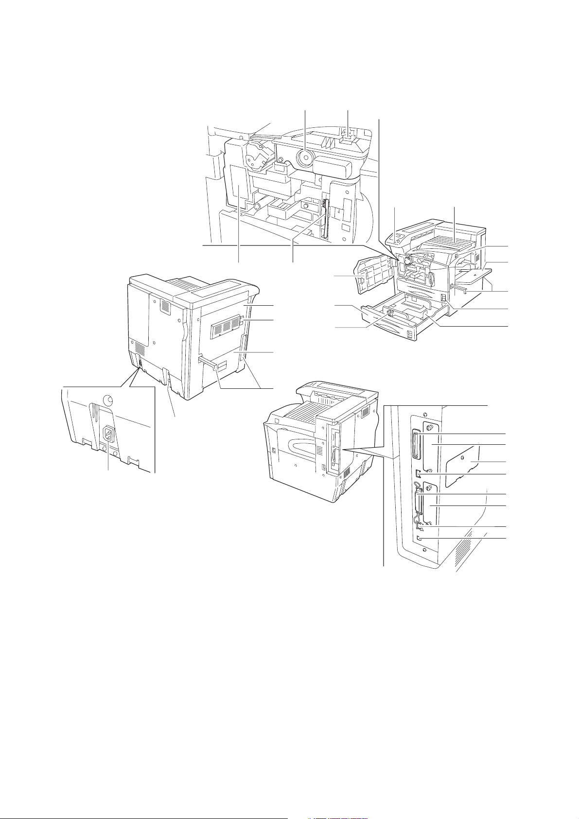
1-1-2 Parts names
(1) Body
2GZ/2G1
13
20
19
18
14
11
12
1
2
3
4
10
9
8
7
6
5
16
15
1. Operation panel
2. Front cover
3. Cassette 2
4. Paper guide
5. Paper stopper
6. Cassette 1
7. Handles for transport
8. MP (Multi-Purpose) tray
9. Main switch
10. Top tray
17
Figure 1-1-1
11. Toner container
12. Toner container release lever
13. Waste toner box
14. Cleaning brush
15. Power cord connector
16. Option unit connector
17. Handles for transport
18. Left cover 2
19. Lock lever
20. Left cover 1
21
22
23
24
25
26
27
28
21. Memory card slot
22. Option interface slot (OPT)
23. Option memory slot cover
24. USB Memory slot (A1)
25. Parallel interface connector
26. Option hard disk unit Slot
(HDD)
27. Network interface connector
28. USB interface connector (B1)
1-1-3
Page 18
2GZ/2G1
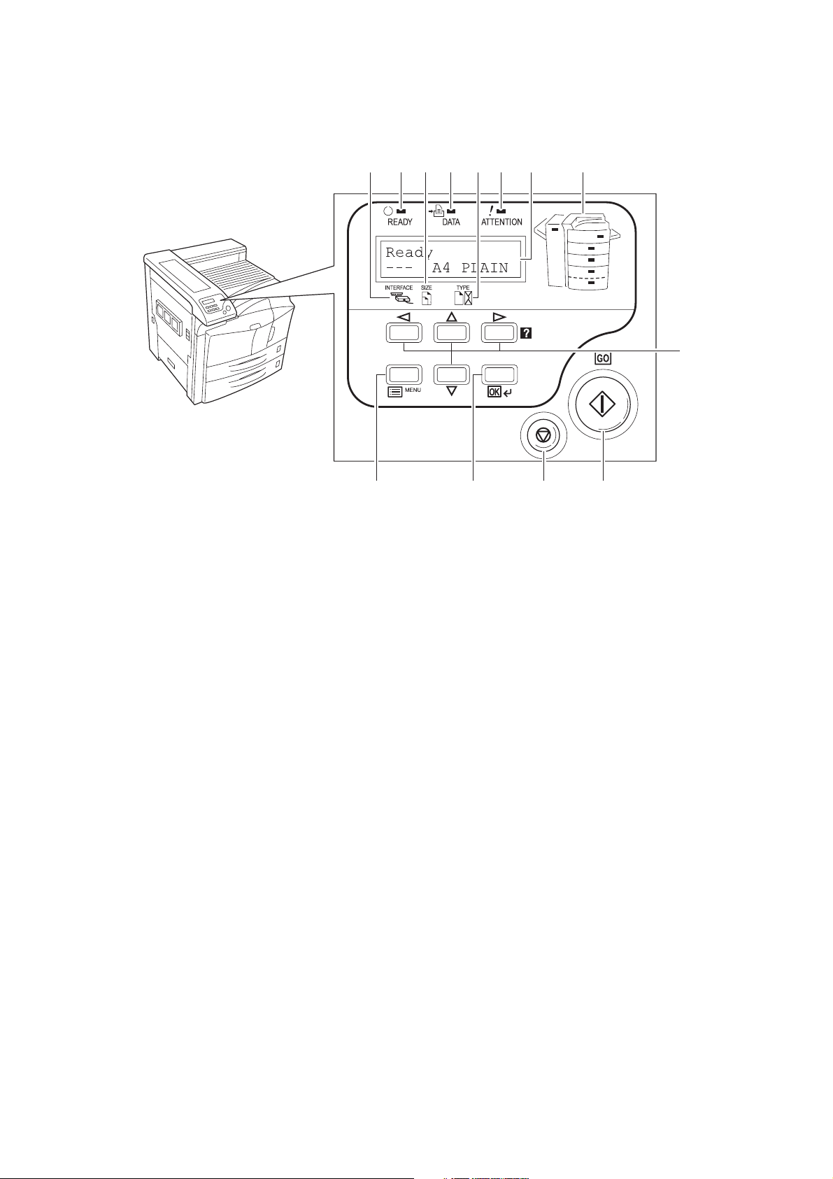
(2) Operation panel
11610
7128 9 13
5
1. GO key
2. CANCEL key
3. OK key
4. MENU key
5. Cursor keys
6. Ready indicator
7. Data indicator
4321
Figure 1-1-2
8. Attention indicator
9. Message display
10. Interface indicator
11. Paper size indicator
12. Paper type indicator
13. Paper jam indicator
1-1-4
Page 19
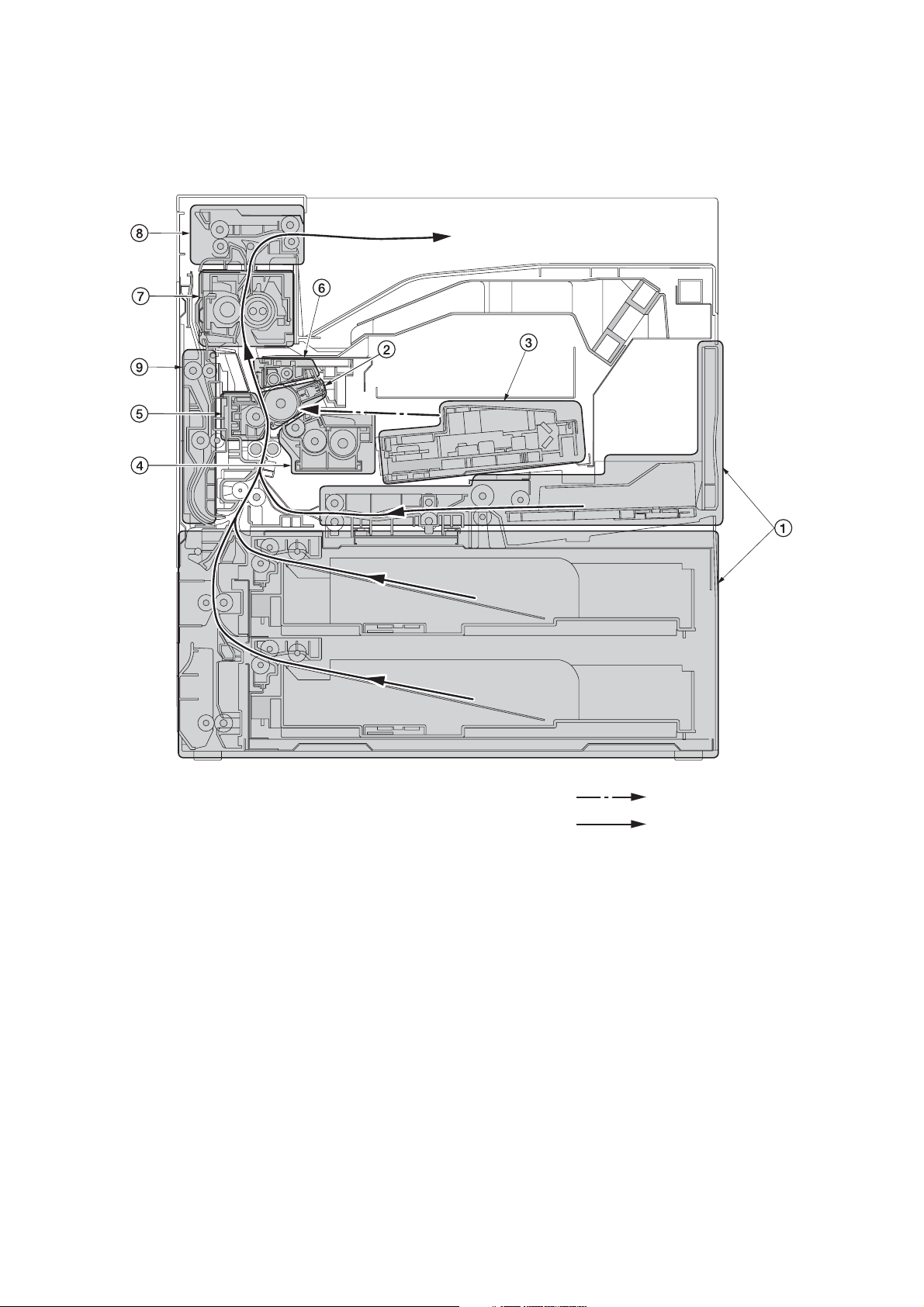
1-1-3 Machine cross section
2GZ/2G1
Figure 1-1-3 Machine cross section
1. Paper feed section
2. Main charging section
3. Laser scanner unit
4. Developing section
5. Transfer and separation section
6. Cleaning and charge erasing section
7. Fuser section
8. Eject and switchback section
9. Duplex section
Light path
Paper path
1-1-5
Page 20

2GZ/2G1
This page is intentionally left blank.
1-1-6
Page 21
1-2 Installation
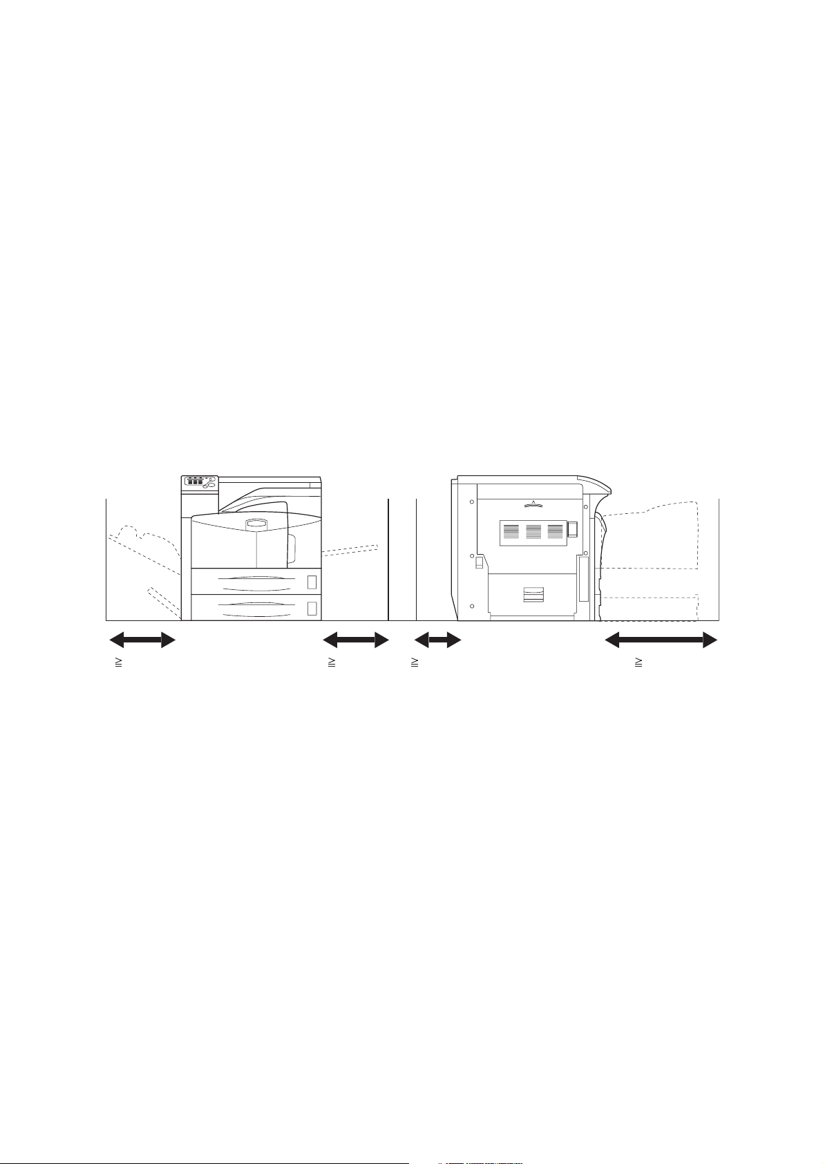
1-2-1 Installation environment
1. Temperature: 10 to 32.5°C/50 to 90.5°F
2. Humidity: 15 to 80%RH
3. Power supply: 120 V AC, max. 11.4 A
220 to 240 V AC, max. 6.1 A
4. Power source frequency: 50 Hz
5. Installation location
Avoid direct sunlight or bright lighting. Ensure that the photoconductor will not be exposed to direct sunlight or
other strong light when removing paper jams.
Avoid extremes of temperature and humidity, abrupt ambient temperature changes, and hot or cold air directed
onto the machine.
Avoid dust and vibration.
Choose a surface capable of supporting the weight of the machine.
Place the machine on a level surface (maximum allowance inclination: 1°).
Avoid air-borne substances that may adversely affect the machine or degrade the photoconductor, such as mercury, acidic of alkaline vapors, inorganic gasses, NOx, SOx gases and chlorine-based organic solvents.
Select a room with good ventilation.
6. Allow sufficient access for proper operation and maintenance of the machine.
Machine front: 1000 mm/39
Machine right: 300 mm/11 13/16" Machine left: 300 mm/11 13/16"
± 0.3%/60 Hz ± 0.3%
3/8" Machine rear: 100 mm/3 15/16"
2GZ/2G1-2
300 mm/
13/16"
11
300 mm/
11 13/16"
100 mm/
15/16"
3
Figure 1-2-1 Installation dimensions
1000 mm/
3/8"
39
1-2-1
Page 22
2GZ/2G1
1-2-2 Unpacking and installation
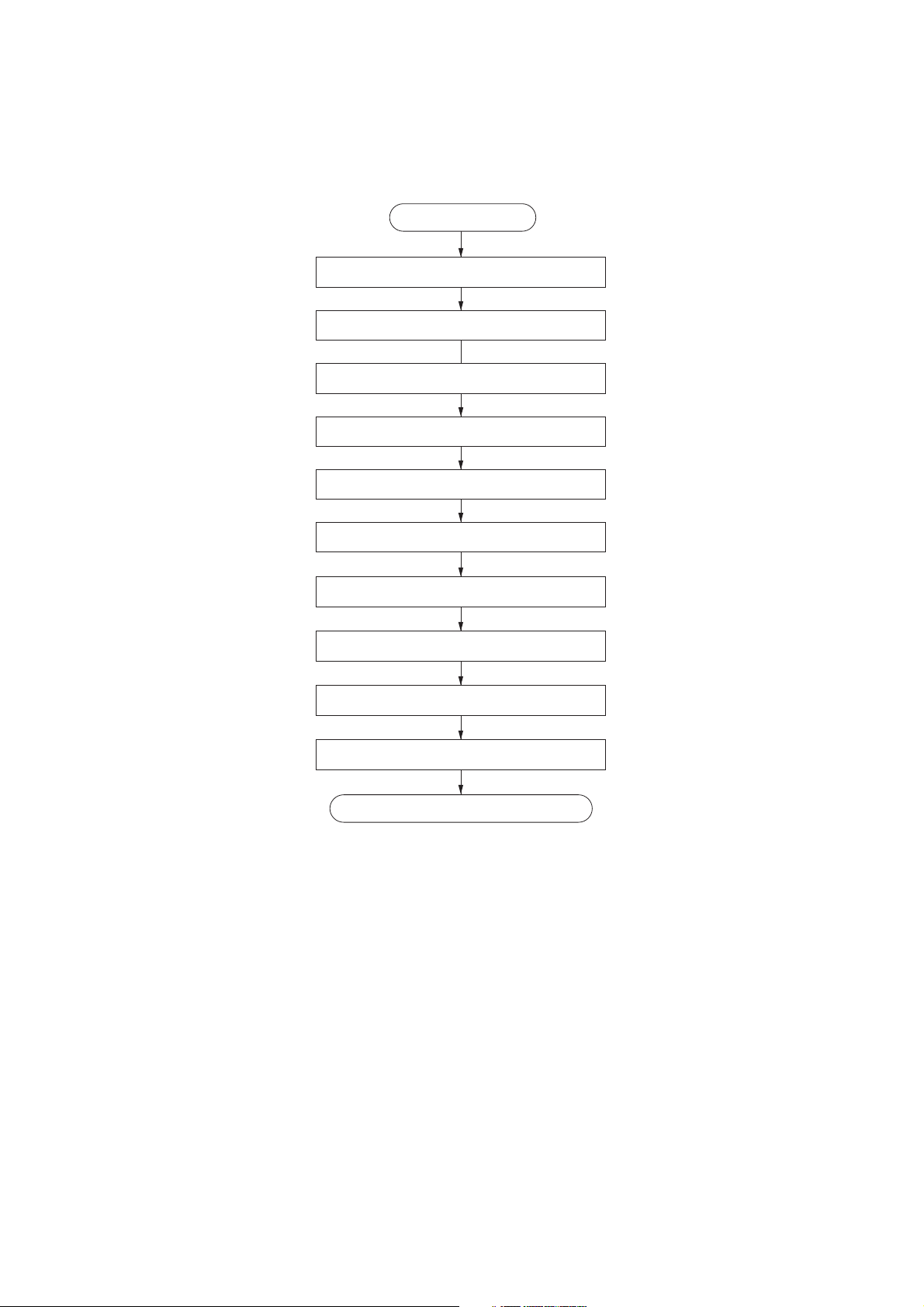
(1) Installation procedure
Start
Unpacking.
Remove the tapes.
Install the optional paper feeder.
Release of cassette lift plate.
Load paper.
Install the toner container.
Install the waste toner box.
Connecting the printer to the computer.
Connect the power cord.
Printing a status page.
Completion of the machine installation.
1-2-2
Page 23
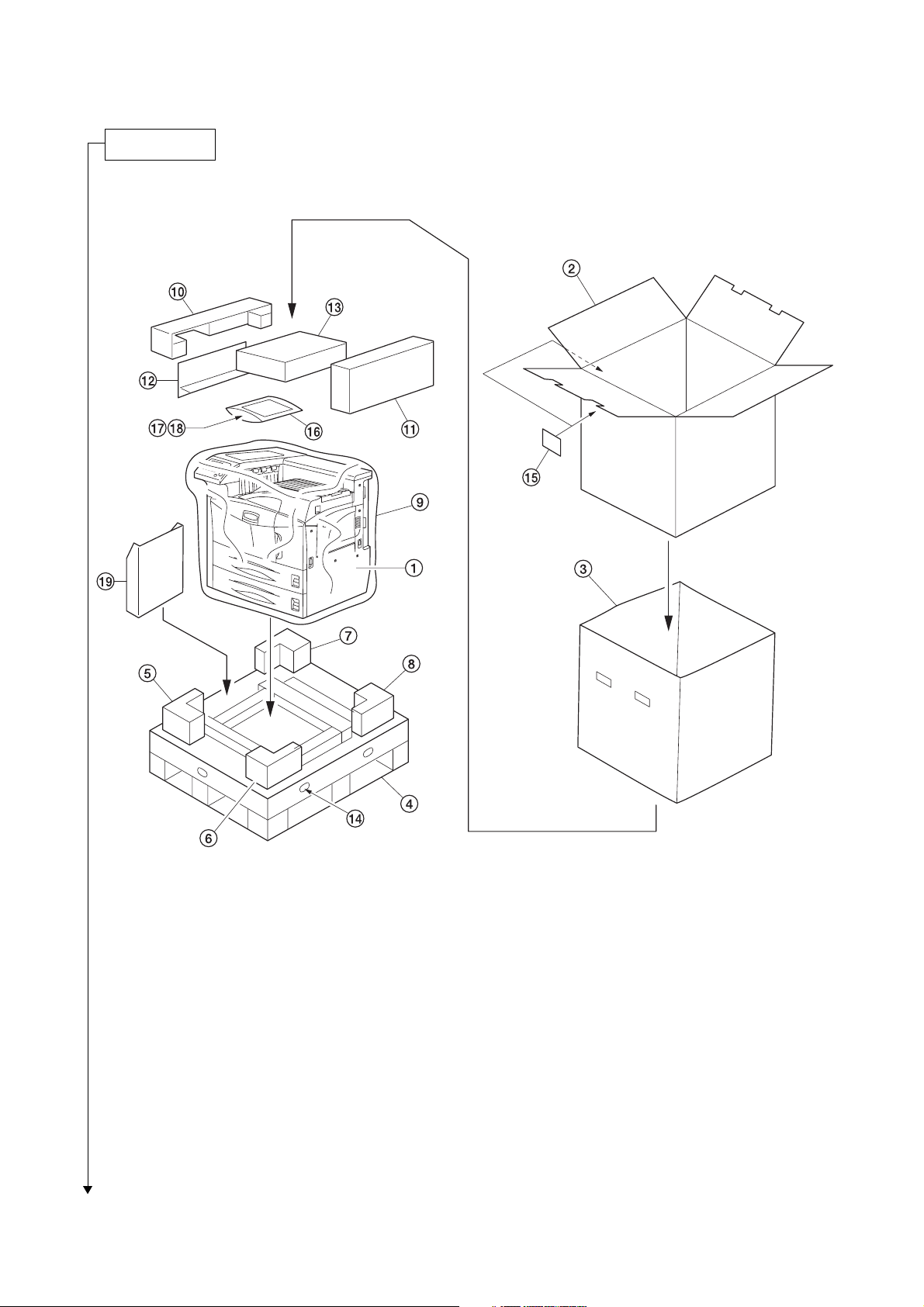
Unpacking.
2GZ/2G1-1
Figure 1-2-2 Unpacking
1. Printer
2. Outer case
3. Inner frame
4. Skid
5. Bottom front left pad
6. Bottom front right pad
7. Bottom rear left pad
8. Bottom rear right pad
9. Machine cover
10. Upper left pad
Caution: Place the machine on a level surface.
11. Upper right pad
12. Spacer
13. Toner container
14. Hinge joints
15. Bar code labels
16. Plastic bag
17. Paper size plates
18. Operation guide
19. Document tray
1-2-3
Page 24
2GZ/2G1
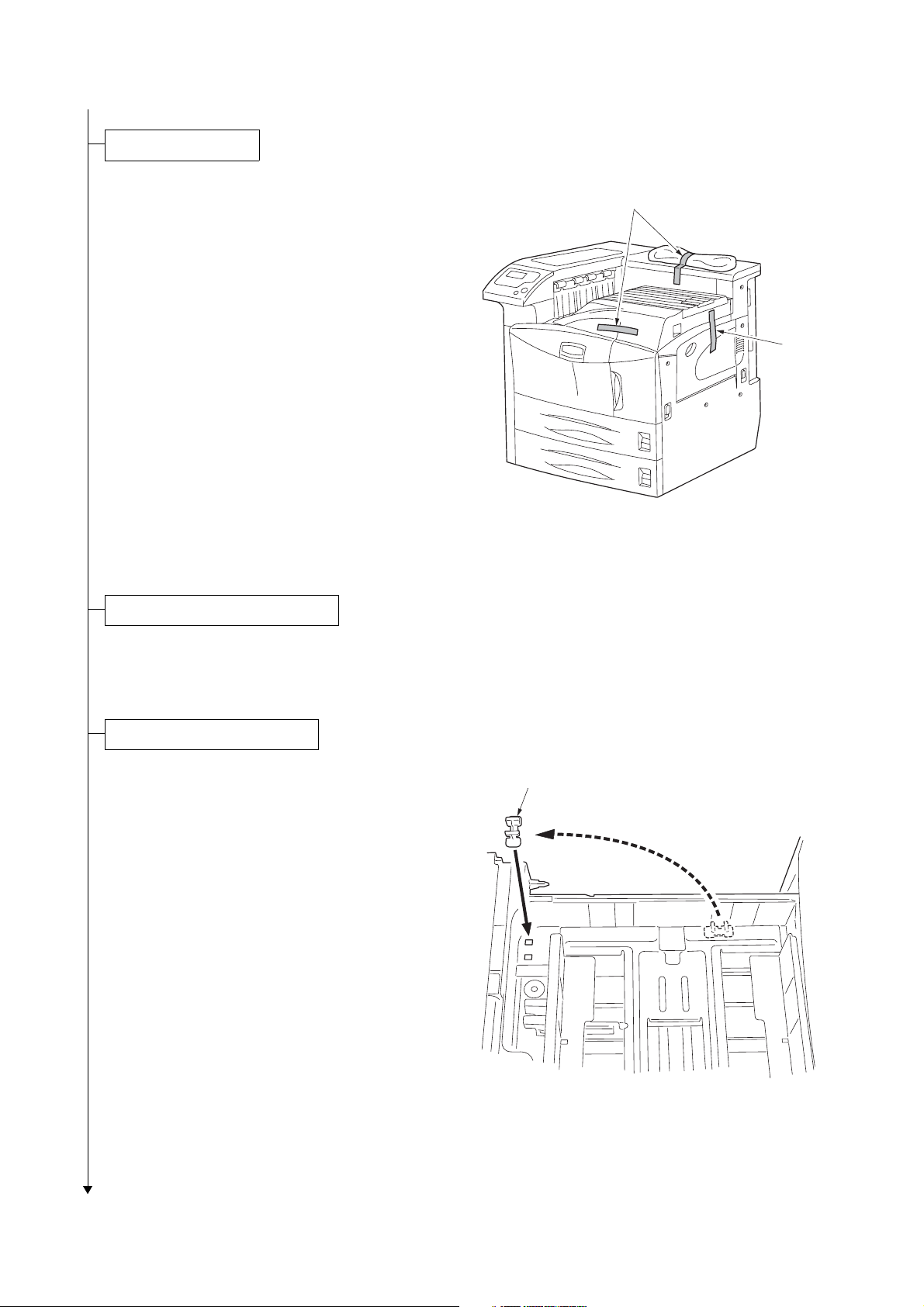
Remove the tapes.
1. Remove three tapes.
Install the optional paper feeder.
Tapes
Tape
Figure 1-2-3
1. Install the optional paper feeder as necessary.
Release of cassette lift plate.
1. Pull cassette 1 and 2 out.
Remove the lift plate stopper from each cassette and attach it to the storage location.
When moving the machine, attach the lift
plate in original position.
Lift plate stopper
Figure 1-2-4
1-2-4
Page 25
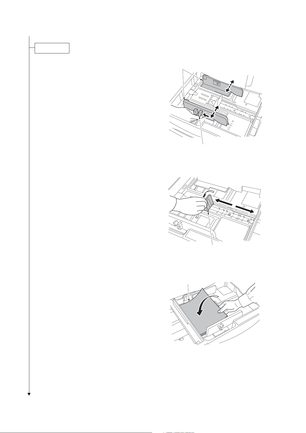
Load paper.
2GZ/2G1-2
1. Pull the cassette out.
2. Holding the paper size adjusting tab both
ends, move the paper guide to fit the paper
size.
3. Adjust the paper stopper to fit the paper
size.
Paper guide
Paper size adjusting tab
Figure 1-2-5
4. Align the paper flush against the left side of
the cassette.
Paper stopper
Figure 1-2-6
Paper
Figure 1-2-7
1-2-5
Page 26
2GZ/2G1
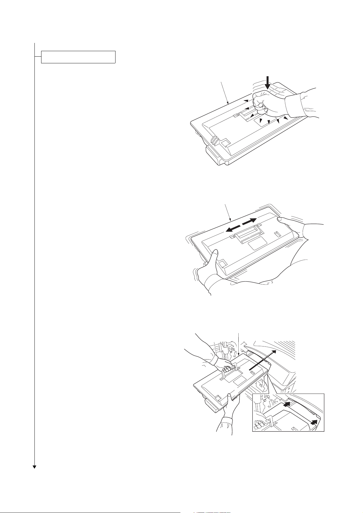
Install the toner container.
1. Open the front cover.
2. Lightly tap the top of the toner container five
to six times.
3. Thoroughly shake the toner container (in the
direction of the arrows) ten times or more to
loosen and mix the toner inside.
Toner container
Figure 1-2-8
Toner container
4. Gently push the toner container into the
machine along the rails.
Push the container all the way into the
machine until it locks in place.
1-2-6
Figure 1-2-9
Toner container
Figure 1-2-10
Page 27
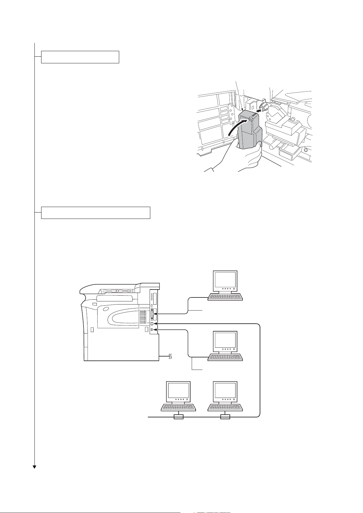
Install the waste toner box.
2GZ/2G1
1. Install the waste toner box in the machine.
2. Close the front cover.
Connecting the printer to the computer.
1. There are various ways of connecting the
printer to the computer, such as through the
parallel interface connector, USB interface
connector, or through the network interface
connector.
Waste toner box
Figure 1-2-11
Printer (Right side)
Power cord
Figure 1-2-12
Parallel interface
USB interface
Network
interface
1-2-7
Page 28

2GZ/2G1-2
Connect the power cord.
1. Connect the power cord to the connector at
the rear side of the machine.
2. Insert the power plug into the wall outlet.
Printing a status page.
1. Turn the main switch on and the toner is
supplied to the development unit for approximately 8 minutes.
2. Press MENU key.
3. Display [Print Status page] using cursor up/
down keys.
4. Press the OK key twice. A status page is
printed.
Completion of the machine installation.
1-2-8
Page 29
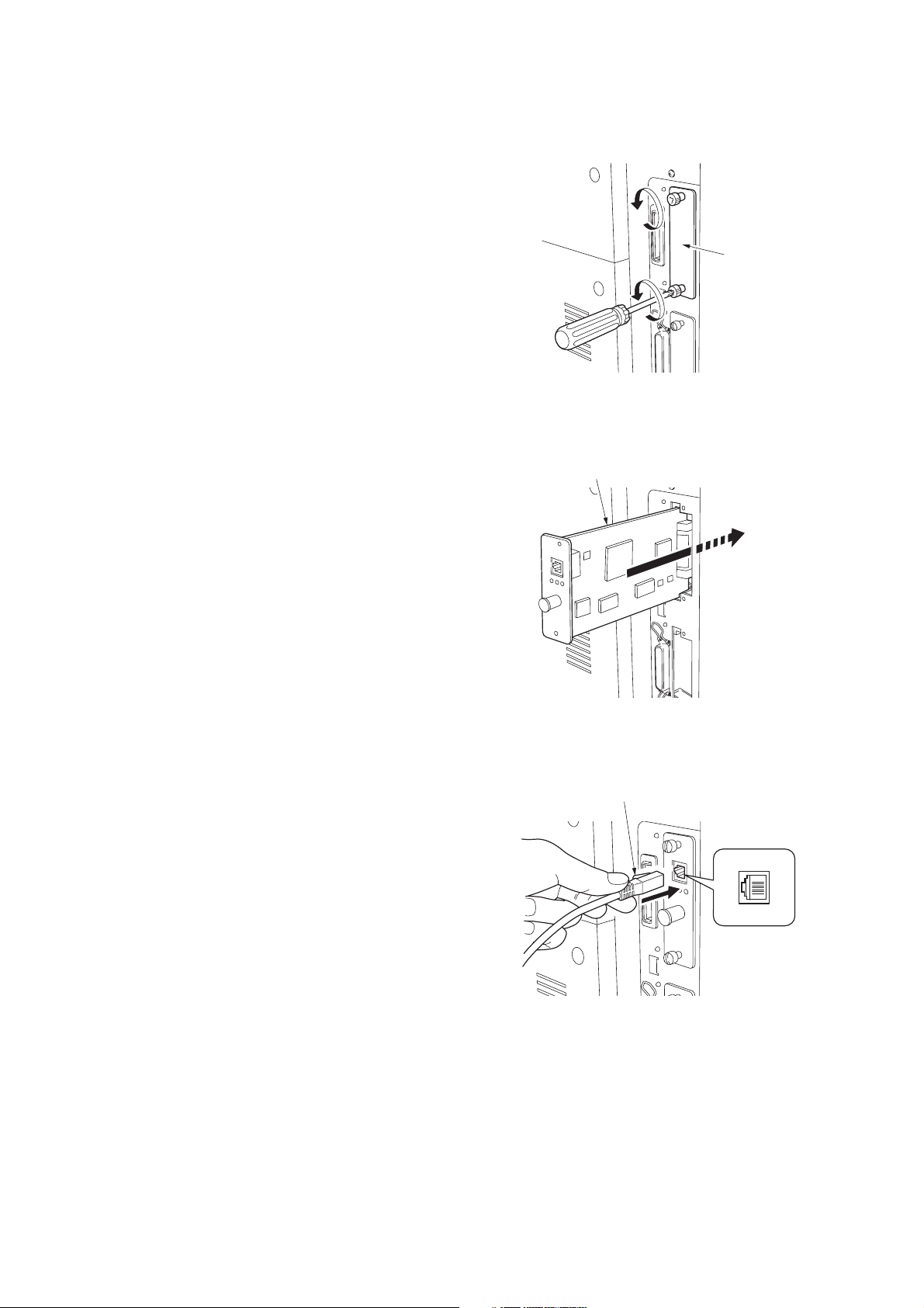
1-2-3 Installing the network interface card (option)
Procedure
1. Remove two screws and remove the inter-
face slot cover (OPT).
2GZ/2G1-2
Interface
slot cover
Figure 1-2-13
2. Insert the network interface card and secure
it with the screws removed in step 1.
3. Connect the network cable.
Network interface card
Figure 1-2-14
Network cable
Figure 1-2-15
1-2-9
Page 30
2GZ/2G1-2
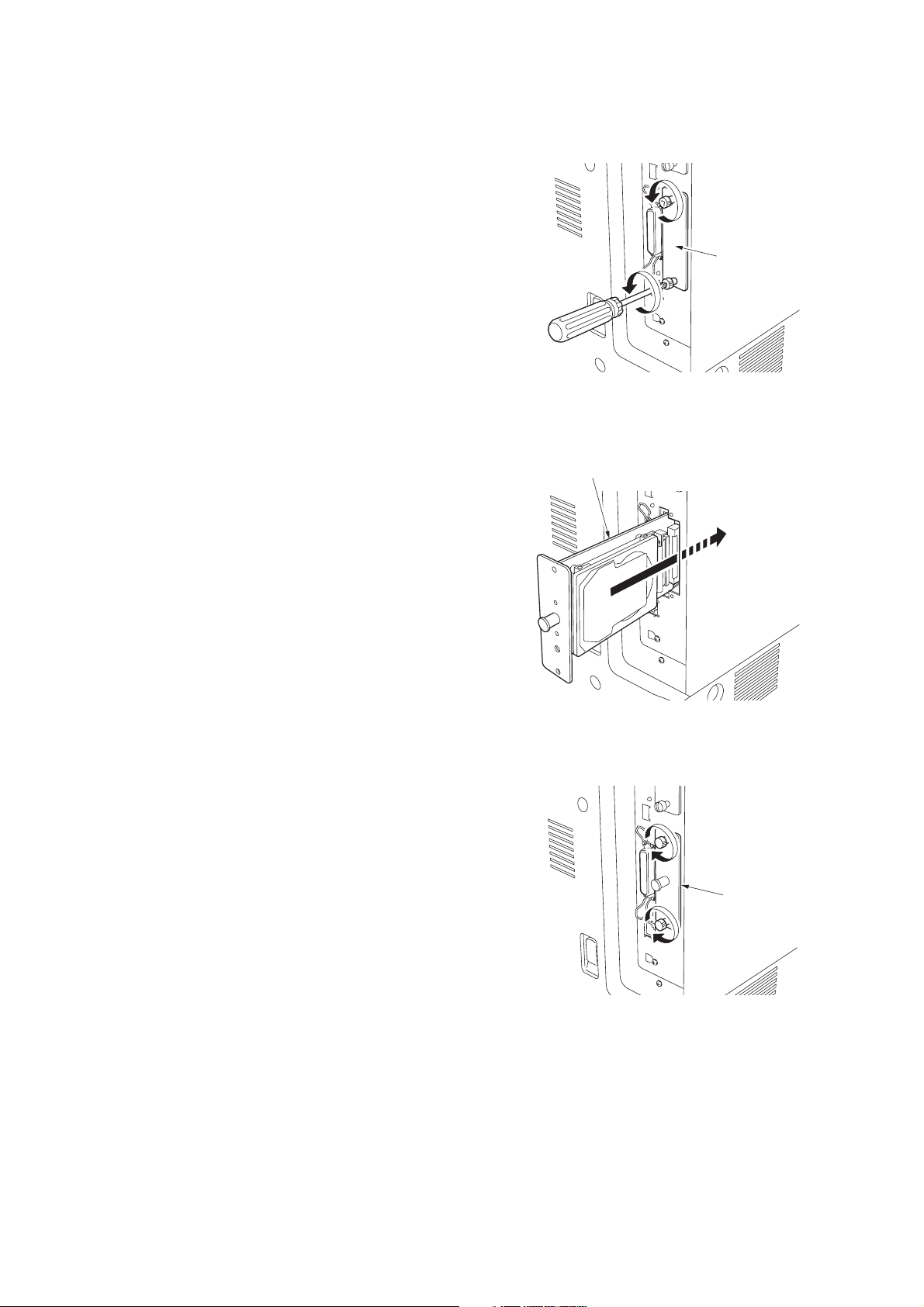
1-2-4 Installing the hard disk unit (option)
Procedure
1. Remove two screws and remove the slot
cover (HDD).
Slot cover
Figure 1-2-16
2. Insert the hard disk unit into the slot.
3. Tighten two screws to secure the hard disk
unit.
Hard disk unit
Figure 1-2-17
Hard disk unit
1-2-10
Figure 1-2-18
Page 31

1-2-5 Installing the CompactFlash card (option)
Procedure
1. Turn the main switch off.
Note: Do not insert or remove a CF card
while power in on. If the CF card is removed
while the machine is on, damage could
result in the machine's electronics or the CF
card.
2. Insert the CF card in the slot. Insert it as its
label surface facing toward outside, connector end first. Push it in all the way.
2GZ/2G1-2
CF card
Figure 1-2-19
1-2-6 Installing the USB memory (option)
Procedure
1. Insert the USB memory in the USB memory
slot.
USB memory
Figure 1-2-20
1-2-11
Page 32

2GZ/2G1-2
1-2-7 Installing the expansion memory (option)
Procedure
1. Remove the screw at the rear side of the
machine and remove the memory slot cover.
2. Open the clips on both ends of the DIMM
socket.
3. Insert the DIMM into the socket, so that the
notches on the DIMM align with the corresponding protrusions in the socket.
4. Close the clips of the DIMM socket to secure
the DIMM.
5. Refit the memory slot cover.
Memory slot cover
Figure 1-2-21
Socket
Clip
Clip
DIMM
Figure 1-2-22
1-2-12
Page 33

2GZ/2G1-2
1-3 Maintenance Mode
1-3-1 Maintenance mode
(1) Maintenance mode
The printer is equipped with a maintenance function which can be used to maintain and service the machine.
To run the maintenance mode, Insert a compact flash card to which the maintenance program has been written into the
printer and load the maintenance mode program to the printer using either method.
* Turn off and on the printer. The maintenance program will be automatically loaded into the printer.
* Load the maintenance mode program with read program.
* Enter the MENU mode and display [>>Maintenance] in the [Memory Card>], then press the OK key.
The maintenance mode can be executed from the MENU mode.
If the compact flash card is removed from the printer and then the printer is turned off and on, the maintenance mode program will be deleted from the printer and the maintenance mode will be deleted from the MENU mode.
(2) Executing a maintenance item
Ready
--- A4 PLAIN
1. Press the MENU key.
Print
Menu Map
Maintenance >
Mode H3SXX
Maintenance >
Mode H3
S XX
Machine
code
2. Press the cursor up/down keys several times until [Maintenance >] is displayed.
3. Press the cursor right key.
Use
Version
S: Service
Maintenance >
Mode H3SXX?
3. Press the OK key.
>Default Setting
[U002] XX
>Print Without
[U005] Paper XXX
>Drive Motors >
[U030]
>Check Switches>
[U031]
The test page is
printed.
Setting the factory default
data
See page 1-3-3.
Printing without paper
See page 1-3-3.
Checking motor operation
See page 1-3-4.
Checking switches for
paper conveying.
See page 1-3-4.
>Check Clutches>
[U032]
Continue to the next page
Checking clutch operation
See page 1-3-5.
1-3-1
Page 34

2GZ/2G1
Continue from the previous
page
>Set Folio Size
[U035] ########
Setting folio size
See page 1-3-5.
>Set Bulk Feeder
[U208] Size ##
Setting the paper size
for the paper feeder
See page 1-3-13.
>Check Cover SW>
[U038]&InterLock
>Set of Paper >
[U051] Loop
>Adjust Motor >
[U053] Speed
>Adjust High >
[U101] Voltage
>Clean Charger
[U102] Cycle ##
>Adjust Toner >
[U112] Refresh
Checking the printer
cover switch
See page 1-3-6.
Adjusting the amount
of slack in the paper
See page 1-3-6.
Setting the adjustment
of the motor speed
See page 1-3-7.
Setting the other high
voltages
See page 1-3-8.
Setting the cleaning
interval for the main
charger
See page 1-3-9.
Setting toner refresh
operation
See page 1-3-9.
>Punch Dest.
[U234] #####
>Adjust Finish.>
[U237]Limit
>Finisher
>[U246] Adjust
>Face-Up Option
[U391] ###
>Print Menu >
[U392]
>Initialize >
[U393]
Setting punch destination
See page 1-3-13.
Setting finisher stack
quantity
See page 1-3-14.
Setting the finisher
See page 1-3-15.
Setting the face-up
unit
See page 1-3-19.
Outputs of the history
of events of the service calls and paper
jam
See page 1-3-20.
Initializing data for
FRPO
See page 1-3-20.
>Setting AC Mode
[U114] Mode #
>Ignore Toner
[U136] Empty ###
>Set Toner Mode
[U144] ######
>Adjust Fixing >
[U161] Heater
>Turn Fixing >
[U196] Heater ON
>Display TEMP >
[U199]
Setting separation
charger mode
See page 1-3-10.
Switching empty toner
status detection
See page 1-3-10.
Setting toner loading
operation
See page 1-3-11.
Setting the fuser control temperature
See page 1-3-11.
Turning the fuser
heater on
See page 1-3-12.
Checking the fuser
temperature
See page 1-3-12.
>Set Paper Feed>
[U394] Top Reg.
>Check MP tray
[U395] Size ###
>Check Cassette>
[U396] Remain
>Set Paper Feed>
[U398] Left Reg.
>Set FRPO >
[U399] Parameter
Continue to the previous page
Adjusting the leading
edge margin of image
printing for each paper
cassette
See page 1-3-21.
Checking the size in
MP tray
See page 1-3-21.
Displaying the amount
of paper remaining in
each paper cassette
See page 1-3-22.
Adjusting left margin
of image printing for
each paper cassette
See page 1-3-22.
Setting FRPO
See page 1-3-23.
1-3-2
Page 35

(3) Contents of maintenance mode items
2GZ/2G1-2
Maintenance
item No.
U002
U005
Description
Setting the factory default data
Description
Restore the machine conditions to the factory default settings.
Purpose
To return the machine settings to initial settings.
Method
1. Enter the maintenance mode and press the cursor up/down keys to display [U002].
2. Press the OK key. [ ? ] will be displayed.
>Default Setting
[U002] ? JP
3. Press the cursor up/down keys to select [JP], [US], [EU] or [AP].
4. Press the OK key. Each setting will be initialized.
To keep the setting, press the CANCEL key.
5. Turn the main switch off and on.
Printing without paper
Description
Switches to the machine operation control without paper
Purpose
To check the overall operation of the machine.
Method
1. Enter the maintenance mode and press the cursor up/down keys to display [U005].
2. Press the OK key. [ ? ] will be displayed.
>Print Without
[U005] Paper?Off
3. Press the cursor up/down keys to turn [On] or [Off] printing without paper.
Initial setting: Off
4. Press the OK key. The setting is set.
To keep the setting, press the CANCEL key.
1-3-3
Page 36

2GZ/2G1
Maintenance
item No.
U030
Description
Checking motor operation
Description
Drives each motor.
Purpose
To check the operation of each motor.
Method
1. Enter the maintenance mode and press the cursor up/down keys to display [U030].
>Drive Motors >
[U030]
2. Press the cursor right key to display the submenu screen.
3. Press the cursor up/down keys to select the motor to activate.
Submenu display Motor
>>FEED Motor Paper feed motor (PFM)
>>MAIN Motor Drive motor (DM)
>>EJECT MT (FW) Eject motor (EM) rotates forward
>>EJECT MT (REW) Eject motor (EM) rotates in reverse
4. Press the OK key. [Execute] will be displayed and operation will start.
>>FEED Motor
[030.1]
U031
5. To stop operation, press the OK key or the CANCEL key.
Checking switches for paper conveying
Description
Displays the on-off status of each paper detection switch on the paper path.
Purpose
To check if the switches for paper conveying operate correctly.
Method
1. Enter the maintenance mode and press the cursor up/down keys to display [U031].
>Check Switches>
[U031]
2. Press the cursor right key to display the submenu screen.
3. Press the cursor up/down keys to select the switch to check.
Submenu display Switches
>>Check SW F1 Feed switch 1 (FSW1)
SW F2 Feed switch 2 (FSW2)
>>Check SW F3 Feed switch 3 (FSW3)
SW MP MP feed switch (MPFSW)
>>Check SW RES Registration switch (RSW)
SW EJE Eject switch (ESW)
>>Check SW BRA Feedshift switch (FSSW)
SW DUP Duplex paper conveying switch (DUPPCSW)
4. Turn on or off the switch manually to check the switch status. 0: Off 1: On
>>Check SW F1 :1
[031.1] SW F2 :1
1-3-4
Page 37

2GZ/2G1-1
Maintenance
item No.
U032
Description
Checking clutch operation
Description
Turns each clutch on.
Purpose
To check the operation of each clutch.
Method
1. Enter the maintenance mode and press the cursor up/down keys to display [U032].
>Check Clutches>
[U032]
2. Press the cursor right key to display the submenu screen.
3. Press the cursor up/down keys to select the clutch to operate.
Submenu display Clutches
>>PF1 Clutch Upper paper feed clutch (PFCL-U)
>>PF2 Clutch Lower paper feed clutch (PFCL-L)
>>PFMP Clutch MP paper feed clutch (MPPFCL)
>>FEED1 Clutch Feed clutch 1 (FCL1)
>>FEED2 Clutch Feed clutch 2 (FCL2)
>>FEED3 Clutch Feed clutch 3 (FCL3)
>>MPTF Clutch MP feed clutch (MPFCL)
>>RES Clutch Registration clutch (RCL)
>>DUPF Clutch Duplex feed clutch (DUPFCL)
4. Press the OK key. [Execute] will be displayed and operation will start.
>>PF1 Clutch
[032.1] Execute
U035
5. To stop operation, press the OK key or the CANCEL key.
Setting folio size
Description
Sets the type of paper when using Folio or Oficioll.
Purpose
To prevent image loss that occurs depending on the difference of paper type.
Method
1. Enter the maintenance mode and press the cursor up/down keys to display [U035].
2. Press the OK key. [ ? ] will be displayed.
3. Press the cursor up/down keys to select folio or oficioll.
>Set Folio Size
[035] ?Folio
Initial setting: Folio
4. Press the OK key. The setting is set.
To keep the setting, press the CANCEL key.
1-3-5
Page 38

2GZ/2G1-2
Maintenance
item No.
U038
Description
Checking the printer cover switch
Description
Displays the on-off status of each cover switch.
Purpose
To check if the switches of covers operate correctly.
Method
1. Enter the maintenance mode and press the cursor up/down keys to display [U038].
>Check Cover SW>
[038]&InterLock
2. Press the cursor left key to display the submenu screen.
3. Press the cursor up/down keys to select the switch to check.
Submenu display Switches
>>Left Cover 1 Left cover 1 switch (LC1SW)
2 Left cover 2 switch (LC2SW)
>>Front Cover Front cover switch (FRCSW)
Int.Lck Safety switch 1,2 (SSW1,2)
4. Open and close the cover to check the switch status. 0: Off 1: On
>>Left Cover 1:1
[038.1] 2:1
U051
Adjusting the amount of slack in the paper
Description
Adjusts the amount of slack in the paper.
Purpose
Make the adjustment if the leading edge of the print image is missing or varies randomly, or if the print paper
is Z-folded.
Method
1. Enter the maintenance mode and press the cursor up/down keys to display [U051].
>Set of Paper >
[U051] Loop
2. Press the cursor right key to display the submenu screen.
3. Press the cursor up/down keys to select the item for which the preset value is to be changed.
Submenu display Description Setting
range
>>RES FEEDER Paper feed from cassette -30 to 20 0
>>RES MPT Paper feed from MP tray -30 to 20 0
>>RES DUP Duplex mode (second) -30 to 20 0
>>RES MPT(THICK) Paper feed from MP tray using thick paper -30 to 20 0
4. Press the OK key. [ _ ] will blink.
>>RES FEEDER
[051.1] ##
Initial
setting
1-3-6
5. Press the cursor right/left keys to move [ _ ] to the digit position at which the value is to be changed and
press the cursor up/down keys to change the preset value.
The greater the value, the larger the amount of slack; the smaller the value, the smaller the amount of
slack.
6. Press the OK key. The value is set.
To keep the preset value, press the CANCEL key.
Page 39

2GZ/2G1-2
Maintenance
item No.
U053
Description
Setting the adjustment of the motor speed
Description
Performs fine adjustment of the speeds of the motors.
Purpose
To adjust the speed of the respective motors when the magnification is not correct.
Method
1. Enter the maintenance mode and press the cursor up/down keys to display [U053].
>Adjust Motor >
[U053] Speed
2. Press the cursor left key to display the submenu screen.
3. Press the cursor up/down keys to select an item for which the preset value is to be changed.
Submenu display Description Setting
range
>>Main Motor Drive motor speed adjustment -40 to 40 0
>>Eject Motor Eject motor speed adjustment -7 to 15 0
>>Polygon Motor Polygon motor speed adjustment -20 to 20 0
4. Press the OK key. [ _ ] will blink.
>>Main Motor
[053.1] ##
Initial
setting
5. Press the cursor right/left keys to move [ _ ] to the digit position at which the value is to be changed and
press the cursor up/down keys to change the preset value.
MAIN MOTOR
Increasing the setting makes the image longer in the auxiliary scanning direction, and decreasing it
makes the image shorter in the auxiliary scanning direction.
POLYGON MOTOR
Increasing the setting makes the image longer in the main scanning direction, and decreasing it makes
the image shorter in the main scanning direction.
EJECT MOTOR
Normally no change is necessary but this can be used as countermeasures against wrinkles (waving) of
paper.
6. Press the OK key. The value is set.
To keep the preset value, press the CANCEL key.
1-3-7
Page 40

2GZ/2G1-2
Maintenance
item No.
U101
Description
Setting the other high voltages
Description
Sets the developing bias control voltage, the transfer control voltage, and the separation control voltage or
checks the output of these voltages.
Purpose
To check the developing bias, the transfer voltage and the separation voltage or to take measures against
drop of image density or background fog.
Method
1. Enter the maintenance mode and press the cursor up/down keys to display [U101].
>Adjust High >
[U101] Voltage
2. Press the cursor right key to display the submenu screen.
3. Press the cursor up/down keys to select an item for which the preset value is to be changed.
Submenu display Description Setting
range
>>DEV BIAS Developing bias AC component frequency at image
formation
>>DEV SBIAS Developing shift bias potential at image formation 0 to 3 0
>>DEV DUTY Developing bias AC component duty at image for-
mation
20 to 32 28
0 to 100 50
Initial
setting
>>TC DATA Transfer control voltage 0 to 300 130
>>SC DATA Separation control voltage 0 to 60 20
Increasing the DEV BIAS setting makes the image darker; decreasing it makes the image lighter.
Increasing the DEV SBIAS setting makes the image darker.
Increasing the DEV DUTY setting makes the image lighter; decreasing it makes the image darker.
Increasing the TC DATA setting makes the transfer voltage higher, and decreasing it makes the voltage
lower.
Increasing the SC DATA setting makes the separation voltage higher, and decreasing it makes the voltage lower.
4. Press the OK key. [ _ ] will blink.
>>DEV BIAS
[101.1] ##
5. Press the cursor left/right keys to move [ _ ] to the digit position at which the value is to be changed and
press the cursor up/down keys to change the preset value.
6. Press the OK key. The value is set.
To keep the preset value, press the CANCEL key.
1-3-8
Page 41

2GZ/2G1
Maintenance
item No.
U102
U112
Description
Setting the cleaning interval for the main charger
Description
Changes the intervals at which the main charger is cleaned.
Purpose
To change the setting when the background is visible.
Setting
1. Enter the maintenance mode and press the cursor up/down keys to display [U102].
2. Press the OK key. [ ? ] will be displayed.
>Clean Charger
[U102] Cycle ? 05
3. Change the setting using the cursor up/down keys.
Description Setting range Initial setting
Main charger cleaning operation intervals 00 to 20 (unit: 1000 pages) 5
When set to 0, the cleaning for the main charger is not operated.
4. Press the OK key. Each setting will be initialized.
To keep the setting, press the CANCEL key.
Setting toner refresh operation
Description
Sets the toner refresh operation time and the developing bias on time at power on and after printing.
Purpose
To change the toner refresh operation time and the developing bias on time at power on and after printing if
image flow level is low.
Setting
1. Enter the maintenance mode and press the cursor up/down keys to display [U112].
>Adjust Toner >
[U112] Refresh
2. Press the cursor right key to display the submenu screen.
3. Press the cursor up/down keys to select an item for which the preset value is to be changed.
Submenu display Description Setting range Initial setting
>>ON TIME Toner refresh operation time 50 to 150 (sec) 120
>>BIAS TIME Developing bias on time 500 to 1000 (msec) 540
4. Press the OK key. [ _ ] will blink.
>>ON TIME
[112.1] ###
5. Press the cursor right/left keys to move [ _ ] to the digit position at which the value is to be changed and
press the cursor up/down keys to change the preset value.
6. Press the OK key. The value is set.
To keep the preset value, press the CANCEL key.
Sec.
1-3-9
Page 42

2GZ/2G1-2
Maintenance
item No.
U114
U136
Description
Setting separation charger mode
Description
Sets the separation charger mode.
Purpose
If the fuser offset occurs, change the setting.
Method
1. Enter the maintenance mode and press the cursor up/down keys to display [U114].
>Setting AC Mode
[U114] Mode 1
2. Press the OK key. [ ? ] will be displayed.
3. Press the cursor up/down keys to select the mode.
Display Description
MODE0 Full page separation for both first and second pages
MODE1 First page: Separation on leading and trailing edges
Second page: Full page sepration
MODE2 Full page sepration is activated for both first and second pages pro-
vided the ambient temperature is less than 19
First page: Separation is activated for both leading and trailing edges,
second page: Full page separation, provided the ambient temperature
is more than 20
MODE3 Separation is activated on both leading and trailing edges for both first
and second pages.
Initial setting: MODE3
4. Press the OK key. The setting is set.
To keep the preset value, press the CANCEL key.
Switching empty toner status detection
Description
Sets whether empty toner status detection is performed when the amount of toner remaining in the toner container is small.
Purpose
If this item is set to ON, when the amount of toner remaining in the toner container is small, printing can be
continued using the toner in the developer unit.
Method
1. Enter the maintenance mode and press the cursor up/down keys to display [U136].
2. Press the OK key. [ ? ] will be displayed.
3. Press the cursor up/down keys to turn on or off empty toner status detection.
>Ignore Toner
[U136] Empty?Off
°C/68°F.
°C/66.2°F.
1-3-10
Initial setting: Off
4. Press the OK key. The setting is set.
To keep the preset value, press the CANCEL key.
Page 43

2GZ/2G1
Maintenance
item No.
U144
U161
Description
Setting toner loading operation
Description
Sets toner loading operation after completion of printing.
Purpose
To set whether or not toner is loaded on the drum after low density printing. Normally no change is necessary
from the initial setting.
Setting
1. Enter the maintenance mode and press the cursor up/down keys to display [U144].
>Set Toner Mode
[U144] Mode 2
2. Press the OK key. [ ? ] will be displayed.
3. Select the item to be set using the cursor up/down keys.
Display Description
Mode 0 Toner not loaded
Mode 1 Toner loaded after simplex or duplex printing
Mode 2 Toner loaded after simplex printing
Initial setting: Mode 2
4. Press the OK key. The setting is set.
To keep the preset value, press the CANCEL key.
Setting the fuser control temperature
Description
Changes the fuser control temperature.
Purpose
Normally no change is necessary. However, can be used to prevent curling or creasing of paper, or solve a
fuser problem on thick paper.
Method
1. Enter the maintenance mode and press the cursor up/down keys to display [U161].
>Adjust Fixing >
[U161] Heater
2. Press the cursor right key to display the submenu screen.
3. Press the cursor up/down keys to select the item for which the preset value is to be changed.
Submenu display Description Setting range Initial setting
>>Drive St. TEMP Driving start temperature when warm-
up starts
>>Ready TEMP(C) Control temperature for displaying
[Ready for printing.]
>>Print TEMP(C) Control temperature during printing
4. Press the OK key. [ _ ] will blink.
>>Drive St. TEMP
[161.1] ###
5. Press the cursor right/left keys to move [ _ ] to the digit position at which the value is to be changed and
press the cursor up/down keys to change the preset value.
6. Press the OK key. The value is set.
To keep the preset value, press the CANCEL key.
0 to 255 (
0 to 255 (
0 to 255 (
°C)
°C)
°C)
185
200
200
1-3-11
Page 44

2GZ/2G1
Maintenance
item No.
U196
U199
Description
Turning the fuser heater on
Description
Turns the fuser heater M or S on.
Purpose
To check fuser heaters turning on.
Method
1. Enter the maintenance mode and press the cursor up/down keys to display [U196].
>Turn Fixing >
[U196] Heater ON
2. Press the cursor right key to display the submenu screen.
3. Press the cursor up/down keys to select the heater to turn on.
Submenu display Description
>>Main Heater ON Fuser heater M (FH-M)
>>Sub Heater ON Fuser heater S (FH-S)
4. Press the OK key. [Execute] will be displayed and the heater will be turned on for three seconds.
Note
Do not open or close the cover when the heater is on. Either do not turn on the heater continuously.
>>Main Heater ON
[196.1] Execute
5. To turn off the heater, press the OK key or the CANCEL key.
Checking the fuser temperature
Description
Displays the fuser temperature, the ambient temperature and the absolute humidity.
Purpose
To check the fuser temperature, the ambient temperature and the absolute humidity.
Method
1. Enter the maintenance mode and press the cursor up/down keys to display [U199].
>Display TEMP >
[U199]
2. Press the cursor right key to display the submenu screen.
>>FIX CENT. TEMP
[U199.1] ###
3. Press the cursor up/down keys to select the item to check.
Submenu display Description
>>FIX CENT. TEMP
>>FIX EDGE TEMP
>>SURROUND TEMP
>>HUMIDITY Absolute humidity (%)
Fuser center temperature (
Fuser edge temperature (
Ambient temperature (°C)
°C)
°C)
1-3-12
Page 45

2GZ/2G1-2
Maintenance
item No.
U208
U234
Description
Setting the paper size for the paper feeder
Description
Sets the size of paper used in optional 3000-sheet paper feeder.
Purpose
To change the setting when the size of paper used in the paper feeder is changed.
Method
1. Enter the maintenance mode and press the cursor up/down keys to display [U208].
2. Press the OK key. [ ? ] will be displayed.
>Set Bulk Feeder
[U208] Size ? A4
3. Press the cursor up/down keys to change the setting.
Display Description
A4 A4 size
B5 B5 size
LT Letter size
4. Press the OK key. The setting is set.
To keep the setting, press the CANCEL key.
Setting punch destination
Description
Sets the destination of optional punch unit of document finisher.
Purpose
To be set when installing a different punch unit from the destination of the machine.
Method
1. Enter the maintenance mode and press the cursor up/down keys to display [U234].
2. Press the OK key. [ ? ] will be displayed.
>Punch Dest.
[U234] ? Nothing
3. Press the cursor up/down keys to change the setting.
Display Description
Nothing With no punch unit
Japan Metric (Japan) specifications
Inch Inch (North America) specifications
Europe Metric (Europe) specifications
Initial setting: Nothing
4. Press the OK key. The setting is set.
To keep the setting, press the CANCEL key.
5. Turn the main switch off and on.
1-3-13
Page 46

2GZ/2G1-2
Maintenance
item No.
U237
Description
Setting finisher stack quantity
Description
Sets the number of sheets of each stack on the main tray and on the internal tray in the optional finisher.
Purpose
To change the setting when a stack malfunction has occurred.
Method
1. Enter the maintenance mode and press the cursor up/down keys to display [U237].
>Adjust Finish.>
[U237]Limit
2. Press the cursor right key to display the submenu screen.
3. Press the cursor up/down keys to select the item for which the preset value is to be changed.
Submenu display Description Setting
>>Main Tray
>>Middle Tray
4. Press the OK key. [ ? ] will blink.
>>Main Tray
[237.1] ? 3000
Number of sheets of stack on the main tray
Number of sheets of stack on the internal tray
for sort or staple printing
range
3000/1500 3000
50/30 50
Initial
setting
5. Press the cursor up/down keys to change the setting.
6. Press the OK key. The value is set.
To keep the setting, press the CANCEL key.
7. Turn the main switch off and on.
1-3-14
Page 47

2GZ/2G1-2
Maintenance
item No.
U246
Description
Setting the finisher
Description
Provides various settings for the optional finisher, if furnished.
Purpose
Adjustment of registration stop timing in punch mode
Adjust if skewed paper conveying occurs or if the paper is Z-folded in punch mode.
Adjustment of paper stop timing in the punch mode
To adjust this item when the position of a punch hole is different from the specified one.
Adjustment of front/rear side registration home position of internal tray
Provides optimization when paper jam occurs due to an inferior fitting of the internal tray adjuster guides to paper.
Adjusting of front and back/slanted stapling home position
Adjusts the stapling position in the staple mode if the position is not proper.
Provides adjustment of slanted stapling.
Adjustment of upper/lower side registration home position of centerfold unit
Provides optimization when paper jam occurs due to an inferior fitting of the centerfold adjuster guides to paper.
Adjustment of booklet stapling position
Adjusts the booklet stapling position in the stitching mode if the position is not proper.
Adjustment of center folding position
Adjusts the center folding position in the stitching mode if the position is not proper.
Start
1. Enter the maintenance mode and press the cursor up/down keys to display [U246].
>Finisher
>[U246] Adjust
2. Press the cursor right key to display the submenu screen.
Submenu display Description
>>Punch Reg Adjustment of registration stop timing in punch mode
>>Punch Pos Adjustment of the paper stop timing in punch mode
>>Width F HP Adjustment of front side registration home position
>>Width R HP Adjustment of rear side registration home position
>>Staple HP Adjustment of front and back stapling home position
>>T-Staple HP Adjustment of slanted stapling home position
>>Width U HP Adjustment of upper side registration home position
>>Width L HP Adjustment of lower side registration home position
>>Staple Pos 1 Adjustment of booklet stapling position for A4/letter size
>>Staple Pos 2 Adjustment of booklet stapling position for B4/legal size
>>Staple Pos 3 Adjustment of booklet stapling position for A3/ledger size
>>Booklet Pos 1 Adjustment of center folding position for A4/letter size
>>Booklet Pos 2 Adjustment of center folding position for B4/legal size
>>Booklet Pos 3 Adjustment of center folding position for A3/ledger size
3. Press the cursor up/down keys to select the item for which the preset value is to be changed.
1-3-15
Page 48

2GZ/2G1-2
Maintenance
item No.
U246
Description
Setting: adjustment of registration stop timing
1. Select [>>Punch Reg].
2. Press the OK key. [ _ ] will blink.
3. Press the cursor right/left keys to move [ _ ] to the digit position at which the value is to be changed and
press the cursor up/down keys to change the preset value.
Setting range: -20 to 20
Initial setting: 0
Change in value per step: 1ms
If skewed paper conveying occurs (sample 1), increase the preset value. If the paper is Z-folded (sample 2), decrease the preset value.
Sample 1 Sample 2
Figure 1-3-1
4. Press the OK key. The value is set.
To keep the preset value, press the CANCEL key.
Setting: adjustment of the paper stop timing
1. Select [>>Punch Pos].
2. Press the OK key. [ _ ] will blink.
3. Press the cursor right/left keys to move [ _ ] to the digit position at which the value is to be changed and
press the cursor up/down keys to change the preset value.
Setting range: -10 to 10
Initial setting: 0
Change in value per step: 0.49mm
If the distance of the position of a punch hole is smaller than the specified value A, increase the preset
value. If the distance is larger than the value A, decrease the preset value.
1-3-16
A
4. Press the OK key. The value is set.
To keep the preset value, press the CANCEL key.
Figure 1-3-2
Preset value A: 5.5
9.5
+
2 mm (inch)
+
2 mm (metric)
-
Page 49

2GZ/2G1
Maintenance
item No.
U246
Description
Setting: adjustment of front/rear side registration home position
1. Select [>>Width F HP] or [>>Width R HP].
2. Press the OK key. [ _ ] will blink.
3. Press the cursor right/left keys to move [ _ ] to the digit position at which the value is to be changed and
press the cursor up/down keys to change the preset value.
Setting range: -10 to 10
Initial setting: 0
Change in value per step: 0.31 ms
4. Press the OK key. The value is set.
To keep the preset value, press the CANCEL key.
Setting: adjustment of front and back stapling home position
1. Select [>>Staple HP].
2. Press the OK key. [ _ ] will blink.
3. Press the cursor right/left keys to move [ _ ] to the digit position at which the value is to be changed and
press the cursor up/down keys to change the preset value.
Setting range: -10 to 10
Initial setting: 0
Change in value per step: 0.32 ms
When staple positions are off toward the front side of the machine (sample 1), increase the preset value.
When staple positions are off toward the rear side of the machine (sample 2), decrease the preset
value.
Sample 1 Sample 2
Figure 1-3-3
4. Press the OK key. The value is set.
To keep the preset value, press the CANCEL key.
Setting: adjustment of slanted stapling home position
1. Select [>>T-Staple HP].
2. Press the OK key. [ _ ] will blink.
3. Press the cursor right/left keys to move [ _ ] to the digit position at which the value is to be changed and
press the cursor up/down keys to change the preset value.
Setting range: -10 to 10
Initial setting: 0
Change in value per step: 0.99
°
To increase the angle for slanted stapling (sample 1), decrease the preset value. To decrease the angle
for slanted stapling (sample 2), increase the preset value.
Sample 1 Sample 2
Figure 1-3-4
4. Press the OK key. The value is set.
To keep the preset value, press the CANCEL key.
1-3-17
Page 50

2GZ/2G1-2
Maintenance
item No.
U246
Description
Setting: adjustment of upper/lower side registration home position
1. Select [>>Width U HP] or [>>Width L HP].
2. Press the OK key. [ _ ] will blink.
3. Press the cursor right/left keys to move [ _ ] to the digit position at which the value is to be changed and
press the cursor up/down keys to change the preset value.
Adjustment of upper side registration home position
Setting range: -20 to 20
Initial setting: 0
Change in value per step: 0.1 mm
Adjustment of lower side registration home position
Setting range: -46 to 46
Initial setting: 0
Change in value per step: 0.1 mm
4. Press the OK key. The value is set.
To keep the preset value, press the CANCEL key.
Setting: adjustment of booklet stapling position
Make sure that the center folding position is correct after adjustment. If the position is not correct, execute the
adjustment of center folding position.
1. Select [>>Staple Pos 1], [>>Staple Pos 2] or [>>Staple Pos 3].
2. Press the OK key. [ _ ] will blink.
3. Press the cursor right/left keys to move [ _ ] to the digit position at which the value is to be changed and
press the cursor up/down keys to change the preset value.
Setting range: -10 to 10
Initial setting: 0
Change in value per step: 0.55 mm
When staples are placed too far right (sample 1), decrease the preset value. When staples are placed
too far left (sample 2), increase the preset value.
Reference value: within
± 2 mm
4. Press the OK key. The value is set.
To keep the preset value, press the CANCEL key.
Sample 1
Figure 1-3-5
2 mm2 mm
Sample 2
1-3-18
Page 51

2GZ/2G1-2
Maintenance
item No.
U246
Description
Setting: adjustment of center folding position
Check the booklet stapling position is correct before adjusting the center folding position.
1. Select [>>Booklet Pos 1], [>>Booklet Pos 2] or [>>Booklet Pos 3].
2. Press the OK key. [ _ ] will blink.
3. Press the cursor right/left keys to move [ _ ] to the digit position at which the value is to be changed and
press the cursor up/down keys to change the preset value.
Setting range: -10 to 10
Initial setting: 0
Change in value per step: 0.55 mm
When the centerfold position too far right (sample 1), increase the preset value. When the centerfold
position too far left (sample 2), decrease the setting value.
Reference value: within
Center line
± 3 mm
3 mm
Sample 1
3 mm
Sample 2
U391
Figure 1-3-6
4. Press the OK key. The value is set.
To keep the preset value, press the CANCEL key.
Setting the face-up unit
Description
Sets whether or not to perform face-up output through the optional face-up unit.
Purpose
To set this mode for special users who install only the face-up unit to perform face-up output. For users who
use both the finisher and the face-up unit, do not set this mode.
Method
1. Enter the maintenance mode and press the cursor up/down keys to display [U391].
2. Press the OK key. [ ? ] will be displayed.
>Face-Up Option
[U391] ? Off
3. Press the cursor up/down keys to select the item.
Initial setting: Off
4. Press the OK key. The value is set.
To keep the preset value, press the CANCEL key.
1-3-19
Page 52

2GZ/2G1-1
Maintenance
item No.
U392
U393
Description
Outputs of the history of events of the service calls and paper jam
Description
Outputs the history of events conditions of the service calls and paper jam.
Purpose
To check the event conditions of the service calls and paper jam.
Method
1. Enter the maintenance mode and press the cursor up/down keys to display [U392].
>Print Menu >
[U392]
2. Press the cursor right key to display the submenu screen.
3. Press the OK key. [ ? ] will be displayed.
>>Print Event
[392.1] Log?
4. Press the OK key. History output starts.
If it will not start, press the CANCEL key.
Initializing data for FRPO
Description
Initializes each preset value of FRPO or NVRAM.
Purpose
TTo reset each preset value of FRPO to the initial values or setting NVRAM for the factory default.
Method
1. Enter the maintenance mode and press the cursor up/down keys to display [U393].
>Initialize >
[U393]
2. Press the cursor right key to display the submenu screen.
3. Press the cursor up/down keys to select the item.
Submenu display Description
>>FRPO INIT Initializes value of FRPO.
>>NVRAM Reset Resets the setting NVRAM for the factory default.
4. Press the OK key. [ ? ] will be displayed.
>FRPO INIT ?
[393.3]
5. Press the OK key. Each setting will be initialized.
To keep the setting, press the CANCEL key.
1-3-20
Page 53

2GZ/2G1-1
Maintenance
item No.
U394
Description
Adjusting the leading edge margin of image printing for each paper cassette
Description
Adjusts the leading edge margin of image printing for each paper cassette.
Purpose
To adjust the leading edge margin if it is displaced depending on the paper cassette.
Method
1. Enter the maintenance mode and press the cursor up/down keys to display [U394].
>Set Paper Feed>
[U394] Top Reg.
2. Press the cursor right/left keys to display the submenu screen.
3. Press the cursor up/down keys to select the item for which the preset value is to be changed.
Submenu display Description Setting
range
>>Cassette 2 Leading edge margin for lower cassette of
the printer
>>Cassette 3 Leading edge margin for upper cassette of
optional paper feeder
>>Cassette 4 Leading edge margin for lower cassette of
optional paper feeder
>>MP Leading edge margin for MP tray -128 to +127 35
>>Duplex Leading edge margin for duplex printing -128 to +127 5
-128 to +127 10
-128 to +127 0
-128 to +127 0
Initial
setting
U395
4. Press the OK key. [ _ ] will blink.
>>Cassette 2
[394.1] ###
5. Press the cursor up/down keys to move [ _ ] to the digit position at which the value is to be changed and
press the cursor up/down keys to change the preset value.
If the preset value is increased, the margin will be larger. If the preset value is decreased, the margin will
be smaller.
6. Press the OK key. The value is set.
To keep the preset value, press the CANCEL key.
Checking the size in MP tray
Description
Displays the size of paper set in the MP tray.
Purpose
To check to see if the size switch of the MP tray operates correctly.
Method
1. Enter the maintenance mode and press the cursor up/down keys to display [U395].
The size of paper set in the MP tray will be displayed.
>Check MP tray
[U395] Size ###
Paper size Display Paper size Display
A3/Ledger 010 B4 011
A4R/Letter-R 008 B5R 009
A4/Letter 108 B5 109
A5 013 B6 015
A6 014 Folio/Legal 051
1-3-21
Page 54

2GZ/2G1-1
Maintenance
item No.
U396
Description
Displaying the amount of paper remaining in each paper cassette
Description
Displays the amount of paper remaining in each paper cassette.
Purpose
To check the amount of paper remaining in each paper cassette.
Method
1. Enter the maintenance mode and press the cursor up/down keys to display [U396].
>Check Cassette>
[U396] Remain
2. Press the cursor right key to display the submenu screen.
3. Press the cursor up/down keys to select the item to check.
Submenu display Description
>>Cassette 1 Amount of paper remaining in cassette 1 (%)
>>Cassette 2 Amount of paper remaining in cassette 2 (%)
>>Cassette 3 Amount of paper remaining in optional cassette 3 (%)
>>Cassette 4 Amount of paper remaining in optional cassette 4 (%)
>>Cassette 1
[396.1] ###%
U398
Display range: 0 - 100% (0: no paper / 100: full)
Adjusting left margin of image printing for each paper cassette
Description
Adjusts the left margin of image printing for each paper cassette.
Purpose
To adjust the left margin if it is displaced depending on the paper cassette.
Method
1. Enter the maintenance mode and press the cursor up/down keys to display [U398].
>Set Paper Feed>
[U398] Left Reg.
2. Press the cursor right key to display the submenu screen.
3. Press the cursor up/down keys to select the item for which the preset value is to be changed.
Submenu display Description Setting range Initial setting
>>Cassette 2 Left margin for cassette 2 -600 to +600 0
>>Cassette 3 Left margin for optional cassette 3 -600 to +600 0
>>Cassette 4 Left margin for optional cassette 4 -600 to +600 0
>>MP Left margin for MP tray -600 to +600 0
>>Duplex Left margin for duplex printing -600 to +600 0
4. Press the OK key. [ _ ] will blink.
>>Cassette 2
[398.1] ###
1-3-22
5. Press the cursor right/left keys to move [ _ ] to the digit position at which the value is to be changed and
press the cursor up/down keys to change the preset value.
If the preset value is increased, the margin will be larger. If the preset value is decreased, the margin will
be smaller.
6. Press the OK key. The value is set.
To keep the preset value, press the CANCEL key.
Page 55

2GZ/2G1
Maintenance
item No.
U399
Description
Setting FRPO
Description
Set the firmware again.
Purpose
To change the preset values of firmware.
Method
1. Enter the maintenance mode and press the cursor up/down keys to display [U399].
>Set FRPO >
[U399] Parameter
2. Press the cursor right key to display the submenu screen.
3. Press the cursor up/down keys to select the item for which the preset value is to be changed.
4. Press the OK key. [ _ ] will blink.
>>FRPO HO
[399.1]
5. Press the cursor right/left keys to move [ _ ] to the digit position at which the value is to be changed and
press the cursor up/down keys to change the preset value.
6. Press the OK key. The value is set.
To keep the preset value, press the CANCEL key.
1-3-23
Page 56

2GZ/2G1
1-3-2 Service mode
The printer is equipped with a maintenance function which can be used to maintain and service the machine.
(1) Executing a service item
Message display
Ready
1. Press the MENU key.
Print
Menu Map
2. Press the cursor up/down keys several
times until [Others >] is displayed.
Others >
Service mode items
3. Press the cursor right key.
>>Print
Status Page
>>Print
Event Log
>>Paper Feed
>>Developer
>MSG Language
English
4. Press the cursor up/down keys several
times until [>Service >] is displayed.
>Service >
5. Press the cursor right key.
To print a status page for service purpose.
(See page page 1-3-25)
To print an event log (EVENT LOG)
(Displayed when FRPO I1 is set to 1)
(See page page 1-3-29)
To set paper feed operation as printer driver
priority mode.
(See page page 1-3-35)
To initialize the developer unit. (toner install mode)
(See page page 1-3-35)
1-3-24
>>Charger
>>Drum
To scroll these items,
press the cursor up/down keys repeatedly.
To perform a main charger wire cleaning.
(See page page 1-3-35)
To perform a drum refreshing.
(See page page 1-3-36)
Page 57

(2) Description of service mode
Service items Description
Printing a status page for service purpose
Description
>>Print
Status Page
Prints a status page for service purpose. The status page includes various printing settings
and service cumulative.
Purpose
To acquire the current printing environmental parameters and cumulative information.
Procedure
1. Enter the service mode [>>Print Status Page].
2. Press the OK key. [Print Status Page?] will be displayed.
3. Press the OK key. Two pages will be printed. (The second page includes service
information.
2GZ/2G1
Service information
(Refer to next page) Firmware release date
Firmware version: 132.00
Service Information
[XXXXXXXX/XXXXXXXX][XXXXXXX][XXXXXXXX][01/00] Printed Page(s) 9690
/t/P00/S00/U00/F00/N00/D50:DM0301.DAN:0002001001210052
/0020/0020/1061/0811/ 0/ 0/ 0/ 0/ 0/ 0/ 0/ 0/ 0/ 0/ 0/ 0/ 0/
/AAAAAAA/AAAAAAA/AAAAAAA/
/AAAAAAA/AAAAAAA/AAAAAAA/
/AAAAAAA/
/AAAAAAA/
/AAAAAAA/AAAAAAA/AAAAAAA/
/AAAAAAA/AAAAAAA/AAAAAAA/AAAAAAA/AAAAAAA/
/0000/0000/0000/0000/0000/
/0000/
/RS2/FF/[0003-0003]/81/31/50/0
00.00.00.00.00.00
A:1234567890123456
Main PWB firmware version
Firmware version: 132.00
Released: 20/Apr/2006
Released: 20/Apr/2006
/03030303/03030303/03030303/03000000/00000000/03030303/03030303/
SPD1:0203040508090A0B0C0D0F101112131415161718191A1B1C1D1E1F202122235E
/00000000/00000000/00000000000000000000000000000000/00000000000000000000000000000000/0000/00/00
/0000000000000000/0000000000000000/0000000000000000/0000000000000000/
/0000000000000000/0000000000000000/0000000000000000/0000000000000000/
/0000000000000000/0000000000000000/0000000000000000/0000000000000000/
/0000000000000000/0000000000000000/0000000000000000/0000000000000000/
DN:SPL9200007 SN:SPL9200010
Figure 1-3-7 Service status page
1-3-25
Page 58

2GZ/2G1
Service items Description
Service information
Service information
[XXXXXXXX/XXXXXXXX][XXXXXXX][XXXXXXXX][01/00] Printed Page(s) 9690
/t/P00/S00/U00/F00/N00/D50:DM0301.DAN:0002001001210052
/0020/0020/1061/0811/ 0/ 0/ 0/ 0/ 0/ 0/ 0/ 0/ 0/ 0/ 0/ 0/ 0/
/AAAAAAA/AAAAAAA/AAAAAAA/
/AAAAAAA/AAAAAAA/AAAAAAA/
/AAAAAAA/
/AAAAAAA/
/AAAAAAA/AAAAAAA/AAAAAAA/
/AAAAAAA/AAAAAAA/AAAAAAA/AAAAAAA/AAAAAAA/
/0000/0000/0000/0000/0000/
/0000/
/RS2/FF/[0003-0003]/81/31/50/0
00.00.00.00.00.00
A:1234567890123456
/03030303/03030303/03030303/03000000/00000000/03030303/03030303/
SPD1:0203040508090A0B0C0D0F101112131415161718191A1B1C1D1E1F202122235E
/00000000/00000000/00000000000000000000000000000000/00000000000000000000000000000000/0000/00/00
/0000000000000000/0000000000000000/0000000000000000/0000000000000000/
/0000000000000000/0000000000000000/0000000000000000/0000000000000000/
/0000000000000000/0000000000000000/0000000000000000/0000000000000000/
/0000000000000000/0000000000000000/0000000000000000/0000000000000000/
DN:SPL9200007 SN:SPL9200010
Detail of service information
No. Items Description
1 Engine ROM information [Mask ROM version/Flash ROM version]
2 Operation panel ROM
information
3 Boot ROM information [Boot ROM version]
1-3-26
[Operation panel mask ROM version]
Page 59

Service items Description
No. Items Description
4 Software jumper switch
information
(hexadecimal)
5 Total p a g e -
6 Toner install information -
7 Parallel I/O information -
8 Serial information 00: Not connected
9 USB information 00: Not connected
10 Operation panel lock sta-
tus (displayed only when
locked)
11 NVRAM error (displayed
only when any error has
occurred)
12 NVRAM download 00: Normal
13 Printable area setting /Top offset/Left offset/Page length/Page width
14 Left offset for each paper
source
15 Top offset for each paper
source
Code conversion
ABCDEF GHI J
0123456789
[First byte/second byte]
First byte
bit 0 = 1: (Fixed)
bit 1 = 0: Overseas,
1: Domestic (Japan)
bit 2, 3 (Not used)
bit 4 = 0: KC, 1: OEM
bit 5 = 0: For Europe, 1: For US
bit 6 = 0: Non MICR mode,
1: MICR mode
bit 7 (Not used)
bit0: Framing error
01: Full-Speed
02: Hi-Speed
01: Partial lock
02: Full lock
01: ID error
02: Version error
bit0: Font data
bit1: Host data
bit2: Macro data
bit3: Program data
bit4: Operation panel message data download (file name displayed)
bit5: OEM data
bit6: Web template data (version displayed)
bit7: Error occurred
/MP tray/Cassette1/Cassette 2/Cassette 3/Cassette 4/Cassette 5/Duplex
(1/600 inches unit)
/MP tray/Cassette 2/Cassette 3/Cassette 4/Cassette 5/Duplex
(1/600 inches unit)
Second byte:
Displayed in OEM mode only.
bit1: Overrun error
bit2: Parity error
03: Checksum error
04: NVRAM crush error
2GZ/2G1-2
16 Offset for rotation /Top offset/Left offset/
(1/600 inches unit)
17 Paper cassette life counter /Total counter (large)/Total counter (small)/MP tray/
18 Paper cassette life counter /Cassette 1 total/Cassette 2 total/Cassette 3 total/
19 Paper cassette life counter /Cassette 4 total/
1-3-27
Page 60

2GZ/2G1-2
Service items Description
No. Items Description
20 Paper source position counter
21 Life counter of each unit /Drum unit/Developer unit/Fuser unit/
22 Document finisher counter /Document finisher total/Main tray total/Centerfold unit/Punch unit/Sta-
23 Version of each unit /3000-sheet paper feeder/Document finisher (software)/Mailbox/Center-
24 Drum ID -
25 Serial interface information RS2: RS-232C
26 Drum sensitivity information -
27 Optional paper feeder/stacker
information
28 Operation panel message lan-
guage
29 Current temperature
/Duplex/
pler/
fold unit/Internal tray (3000-sheet document finisher)
RS4: RS-422A
[First 2 bytes - Second 2 bytes]
First 2 bytes
bit0: MP tray
bit1 to 4: Cassette 1 to 4
bit5 to 6: Reserved
bit7: Duplex
bit8: 3000-sheet paper feeder
bit9: Reserved
bit10: Paper feeder
bit11 to 15: Reserved
PMSG command setting (decimal)
0 to 100 °C/32 to 212 °F (in 1 °C/1.8 °F increment, “-” = Temperature/
humidity sensor is abnormal.)
Second 2 bytes
bit0: Face up
bit1: Face down
bit2: Reserved
bit3: Mailbox
bit4: Document finisher
bit5 to 15: Reserved
30 Current humidity 0 to 100% RH (in 1% increment)
31 Number of rebooting for verti-
cal distortion check
32 MAC address -
33 Fixed asset number (maximum 16 characters)
34 Media type attributes Media type setting value from 1 to 28 (paper weight)
35 Memory SPD information (slot 1)2 to 6 bytes, 8 to 36 bytes, 94 to 95 bytes (total 32 bytes)
36 Toner container information -
37 Parameters of maintenance
mode
38 Drum serial number -
39 Machine serial number -
NOTE:
Code conversion
ABCDEFGH I J
0123456789
-
(unused media type (18 to 20) are always 0x00.)
-
1-3-28
Page 61

Service items Description
Printing an event log (EVENT LOG)
Description
>>Print
Event Log
Prints the history of paper misfeeds and self-diagnostic errors including up to 16 items from
the latest occurrence of such an error. (If the number of errors exceeds 16, errors will be
deleted sequentially from the oldest one.)
Purpose
To allow machine malfunction analysis based on the frequency of paper misfeeds and self
diagnostic errors.
Procedure
1. Enter the service mode [>>Print Event log].
2. Press the OK key. [>>Print Event Log?] will be displayed.
3. Press the OK key. A sheet of event log will be printed.
2GZ/2G1-2
[0000000000000000][0000000000000000][0000000000000000][01]
(1)
Printed Page(s) 12345 DN:ABCDEFG/ABCDEFG/ABCDEFG/ABCDEFG/
(10)
# Count. Event # Count. Service Code
16 11111 10.31.01.88.15.01
15 10000 10.31.01.88.15.01
14 9999 10.31.01.88.15.01
13 9998 10.48.01.88.01.01
12 9997 10.31.01.88.15.01
11 9996 10.31.01.88.15.01
10 9995 10.31.01.88.15.01
9 9994 10.31.01.88.15.01
8 9993 10.31.01.88.15.01
7 9992 10.31.01.88.15.01
6 9991 10.31.01.88.15.01
5 9990 10.31.01.88.15.01
4 9989 10.31.01.88.15.01
3 9979 10.31.01.88.15.01
2 9969 10.31.01.88.15.01
1 1 10.31.01.88.15.01
(13)
J00: 0 J43: 0 C:6000: 4 T00: 1
J05: 0 J44: 0 C:6050: 1
J09: 0 J46:
J10: 0 J47:
J11: 0 J50:
J12: 0 J51:
J13: 0 J52:
J14: 0 J53:
J15: 0 J60:
J16: 0 J61:
(g)
J17: 0 J80:
J18: 0 J81:
J19: 0 J82:
J20: 0 J83:
J21: 0 J84:
J22: 0 J85:
J23: 0 J86:
J30: 0 J87:
J35: 0 J88:
J40: 0 J89:
J41: 0
J42: 0
SN: ABCDEFG
(7)
10.31.01.88.15.01
(a) (b) (c) (d) (e) (f)
(h)
(9)
(4)(2) (3) (5)
(8)
(11)
8 11234 01.6000
7 10000 01.6000
6 9999 01.6000
5 9998 01.6000
4 9997 01.6000
3 9996 01.6000
2 9995 01.6000
1 9994 01.6000
(12)
# Count. item
8 11234 01.00
7 10000 01.00
6 9999 01.00
5 9998 01.00
4 9997 01.00
3 9996 01.00
2 9995 01.00
1 9994 01.00
Firmware version: 130.00eval020A-8
(i)
Released: 29/AUG/2006
(6)
Figure 1-3-8 Event log
1-3-29
Page 62

2GZ/2G1-2
Service items Description
Detail of event log (EVENT LOG) information
No. Items Description
(1) Engine PWB mask version [Engine mask version/Engine software version]
(2) Operation panel PWB mask ver-
sion
(3) BROM version -
(4) Software jumper switch informa-
tion (hexadecimal)
(5) Main PWB firmware mask ver-
sion
(6) Main PWB firmware release
date
(7) Total page counter -
(8) Drum serial number -
(9) Machine serial number -
(10) Paper Jam Log # Count. Event
-
[First byte/Second byte]
First byte
bit 0 = 1: (Fixed)
bit 1 = 0: Overseas, 1: Domestic (Japan)
bit 2, 3 (Not used)
bit 4 = 0: KC, 1: OEM
bit 5 = 0: For Europe, 1: For US
bit 6 = 0: Non MICR mode, 1: MICR mode
bit 7 (Not used)
-
-
Remembers 1 to 16 of
occurrence. If the occurrence of the previous
paper jam is less than
16, all of the paper jams
are logged. When the
occurrence excessed
16, the oldest occurrence is removed.
The total page count
at the time of the
paper jam.
Second byte:
Displayed in OEM
mode only
Log code (2 digit,
hexadecimal, 6
categories)
(a) Cause of a
paper jam
(b) Position of
paper jam
(c) Paper source
(d) Paper size
(e) Paper type
(f) Paper exit
1-3-30
Refer to the next
page for the details
of each log code.
Page 63

Service items Description
No. Items Description
2GZ/2G1-2
(10)
cont.
(a) Cause of paper jam (Hexadecimal)
04: Cover opened. [00]
05: Memory read ready time-out (secondary paper feed does not start). [4D]
09: Sequence error (3000-sheet paper feeder). [33]
10: No paper feed (cassette 1). [31]
11: No paper feed (cassette 2). [32]
12: No paper feed (cassette 3: paper feeder/3000-sheet paper feeder). [33]
13: No paper feed (cassette 4: paper feeder). [34]
14: No paper feed (MP tray). [42]
15: Jam in horizontal paper conveying section. Paper path sensor 3 (PPSENS3) non-
arrival jam (3000-sheet paper feeder). [33]
16: Jam in horizontal paper conveying section. Paper path sensor 2 (PPSENS2) non-
arrival jam (3000-sheet paper feeder). [33]
17: Jam in horizontal paper conveying section. Paper path sensor 1 (PPSENS1) non-
arrival jam (3000-sheet paper feeder). [33]
18: Jam in vertical paper feed section. [4D]
19: Jam in vertical paper feed section (paper feeder). [43]
20: Jam in MP tray paper conveying section. [48]
21: Multiple sheets in paper feed section. [4D]
22: Multiple sheets in vertical paper conveying section. [4D]
23: Multiple sheets in MP tray paper conveying section. [48]
30: Jam in registration/transfer section. [4D]
40: Jam in fuser section (paper feed from MP tray). [4D]
41: Jam in fuser section (paper feed from cassette 1). [4D]
42: Jam in fuser section (paper feed from cassette 2). [4D]
43: Jam in fuser section (paper feed from cassette 3: paper feeder). [4D]
44: Jam in fuser section (paper feed from cassette 4: paper feeder). [4D]
45: Jam in fuser section (paper feed from 3000-sheet paper feeder). [4D]
46: Jam in fuser section (paper refeed from duplex section). [4D]
50: Jam in eject section. [4D]
52: Jam in feedshift section. [4D]
60: Jam in duplex paper conveying section 1. [4D]
61: Jam in duplex paper conveying section 2. [4D]
80: Jam between the printer and 3000-sheet document finisher. [46]
81: Paper entry sensor (PES) non-arrival jam (3000-sheet document finisher). [46]
Paper entry sensor1/2 (PES1/PES2) non-arrival jam (document finisher). [46]
82: Jam in stapler (3000-sheet document finisher/document finisher). [46]
83: Exit sensor (ESW1) stay jam (3000-sheet document finisher). [46]
Exit sensor (EXS) stay jam (document finisher). [46]
84: Jam in eject section of right sub tray (3000-sheet paper feeder). [46]
85: Jam in eject section of left sub tray (3000-sheet paper feeder). [46]
86: Jam in eject section of internal tray 1 (3000-sheet paper feeder). [46]
87: Jam in eject section of internal tray 2 (3000-sheet paper feeder). [46]
88: Jam in eject section of main tray (3000-sheet paper feeder). [46]
89: Jam in centerfold unit (3000-sheet document finisher). [50]
90: Jam in mailbox (3000-sheet document finisher). [51]
91: Document finisher cover opened. [46]
92: Exit sensor (EXS) non-arrival jam (document finisher). [46]
93: Reverse sensor (REVS) jam (document finisher). [46]
94: Paper entry sensor (PES) stay/remaining jam (document finisher). [46]
95: Paper conveying sensor (PCS) jam (document finisher). [46]
Note:
Values (hexadecimal) within [ ] indicate paper misfeed locations, see next page.
1-3-31
Page 64

2GZ/2G1-2
(Stapler)
FSSW
ESW
RSW
MPFSW
FSW2
FSW3
PPS
ENS1
PPS
ENS2
PPS
ENS3
DUP
PCSW
(Duplex)
MPESW
TEJS
ESW2
ITPES1
ESW1
SRHPS2
SRHPS1
ITPES2
PCBMDS
CPES
CSRS2
CPDS
CSRS1
CESW
PES
PES
TEJS
ESW3
PCS
EXS
REVS
PES1
PES2
(Cassette 1)
(Cassette 2)
(Cassette 3)
(Cassette 4)
(Main tray)
(Left
sub tray)
(MP tray)
(Fuser)
FSW1
(Internal tray)
(Registration
/transfer)
Service items Description
No. Items Description
(10)
(b) Detail of jam location (Hexadecimal)
cont.
(Trays 1 to 7)
TEJS
TEJS
51
Mailbox
(Left
(Left
sub tray)
sub tray)
(Main tray)
(Main tray)
3000-sheet
document
finisher
ESW1
ESW1
ESW3
ESW3
SRHPS1
SRHPS1
TEJS
TEJS
MPESW
MPESW
ITPES1
ITPES1
SRHPS2
SRHPS2
(Internal tray)
(Internal tray)
(Right sub tray)
ESW2
ESW2
PES
PES
PES
46
ITPES2
ITPES2
PCBMDS
PCBMDS
(Duplex)
(Duplex)
DUP
DUP
PCSW
PCSW
Document
finisher
(Feedshift)
FSSW
FSSW
ESW
ESW
(Fuser)
(Fuser)
4D
(Registration
(Registration
/transfer)
/transfer)
RSW
RSW
FSW1
FSW1
FSW2
FSW2
(Eject)
MPFSW
MPFSW
Printer
48
31
PCS
PCS
EXS
EXS
(Cassette 1)
(Cassette 1)
46
REVS
REVS
(MP tray)
(MP tray)
42
PES1
PES1
PES2
PES2
CESW
CESW
CSRS1
CSRS1
CPDS
CPDS
Centerfold unit
(c) Detail of paper source (Hexadecimal)
00: MP tray
01: Cassette 1
02: Cassette 2
03: Cassette 3 (paper feeder)
04: Cassette 4 (paper feeder)
43
FSW3
PPS
PPS
ENS1
ENS1
43
FSW3
50
(Stapler)
(Stapler)
CSRS2
CSRS2
CPES
CPES
07: Duplex
08: 3000-sheet paper feeder
05/06/09: Reserved
(Cassette 2)
32
PPS
PPS
ENS2
ENS2
33
3000-sheet paper feeder
33
34
Paper feeder
(Cassette 2)
PPS
PPS
ENS3
ENS3
(Cassette 3)
(Cassette 3)
(Cassette 4)
(Cassette 4)
1-3-32
Page 65

Service items Description
No. Items Description
(10)
cont.
(d) Detail of paper size (Hexadecimal)
01: Monarch
02: Business
03: International DL
04: International C5
05: Executive
06: Letter-R
86: Letter-E
07: Legal
08: A4R
88: A4E
09: B5R
89: B5E
0A: A3
0B: B4
(e) Detail of paper type (Hexadecimal)
0C: Ledger
0D: A5R
8D: A5E
0E: A6
0F: B6
10: Commercial #9
11: Commercial #6
12: ISO B5
13: Custom size
1E: C4
1F: Postcard
20: Reply-paid postcard
21: Oficio II
22: Special 1
2GZ/2G1-2
23: Special 2
24: A3 wide
25: Ledger wide
26: Full bleed paper
(12 × 8)
27: 8K
28: 16K-R
A8: 16K-E
32: Statement-R
B2: Statement-E
33: Folio
34: Western type 2
35: Western type 4
00: (Not specified)
01: Plain
02: Transparency
03: Preprint
04: Labels
05: Bond
06: Recycle
07: Vellum
08: Rough
(f) Detail of paper exit location (Hexadecimal)
01: Face down (FD)
02: Face up (FU)/
Document finisher face up (FU)/
3000-sheet document finisher left sub tray (FU)
03: Document finisher face-down (FD)
04: Document finisher sub tray (FD)
05: Reserved
06: 3000-sheet document finisher right sub tray (FU)
07: 3000-sheet document finisher left sub tray (FD)
09: 3000-sheet document finisher right sub tray (FD)
0B: Mailbox tray 1 (FD)
0C: Mailbox tray 1 (FU)
0D: Mailbox all tray (FD)
0E: Mailbox all tray (FU)
09: Letter head
0A: Color
0B: Prepunched
0C: Envelope
0D: Cardstock
0E: Coated
0F: 2nd side
10: Media 16
11: High quality
15: Custom 1
16: Custom 2
17: Custom 3
18: Custom 4
19: Custom 5
1A: Custom 6
1B: Custom 7
1C: Custom 8
15: Mailbox tray 2 (FD)
16: Mailbox tray 2 (FU)
1F: Mailbox tray 3 (FD)
20: Mailbox tray 3 (FU)
29: Mailbox tray 4 (FD)
2A: Mailbox tray 4 (FU)
33: Mailbox tray 5 (FD)
34: Mailbox tray 5 (FU)
3D: Mailbox tray 6 (FD)
3E: Mailbox tray 6 (FU)
47: Mailbox tray 7 (FD)
48: Mailbox tray 7 (FU)
1-3-33
Page 66

2GZ/2G1-2
Service items Description
No. Items Description
(11) Service Call (Self diag-
nostic error) Log
(12) Maintenance Log # Count. Item
(13) Counter Log
Comprised of three log
counters including paper
jams, self diagnostics
errors, and replacement of
the toner container.
# Count. Self diagnostic error
code
Remembers 1 to 8 of
occurrence of self diagnostics error. If the occurrence of the previous
diagnostics error is less
than 8, all of the diagnostics errors are logged.
Remembers 1 to 8 of
occurrence of replacement. If the occurrence of
the previous replacement
of toner container is less
than 8, all of the occurrences of replacement are
logged.
(g) Jam (h) Self diagnostic error (i) Maintenance item
Indicates the log counter
of paper jams depending
on location.
Refer to Paper Jam Log.
All instances including
those are not occurred
are displayed.
The total page count at
the time of the self diagnostics error.
The total page count at
the time of the replacement of the toner container.
This is virtually logged
as the occurrence of the
Toner Empty condition
since the replacement of
the toner container is not
precisely detectable.
Indicates the log counter
of self diagnostics errors
depending on cause.
(See page 1-4-18)
Example:
C6000: 4
Self diagnostics error
6000 has happened four
times.
Indicates the self
diagnostic errors and
codes.
(See page 1-4-18)
Example:
01.6000
01: Self diagnostic
error
6000: Self diagnostic
error code number
Code of maintenance replacing item
(1 byte, 2 categories)
First byte (Replacing item)
01: Toner container
02: Maintenance kit
Second byte (Type
of replacing item)
00: (fixed)
Indicates the log
counter depending
on the maintenance
item for maintenance.
T: Toner container
00: Black
M: Maintenance kit
00: (fixed)
replacing
1-3-34
Example:
T00: 1
The (black) toner
container has been
replaced once.
Page 67

Service items Description
Setting the paper feed operation (printer driver priority mode)
>>Paper Feed
Description
With printer driver priority mode, when selecting the specific paper feed location (a cassette
or MP tray) with the printer driver (it is not automatic selection), paper is fed from the
selected location. Message "Add Paper" is displayed when there is no paper in that location.
When selecting the MP tray as the paper feed location, paper is fed with the timing of maximum size. As for the setting media type (setting the paper type), setting of the printer driver
is notified to the engine PWB. Duplex printing operation is still the ordinary operation, and
paper jam occurs if paper size is different from the setting of the printer.
Purpose
To set the printer driver priority mode which priority is given to the setup of a printer driver
when the ordinary paper feed operation mode is not suitable for the usage condition of the
user.
Method
1. Enter the service mode [>>Paper feed].
2. Press the OK key. Message [Paper feed?] will be displayed.
3. Select the mode (Normal? or Special?) pressing the cursor up/down keys.
Normal Ordinary paper feed operation mode
Special Printer driver priority mode
4. Press the OK key.
Completion
2GZ/2G1
>>Developer
>>Charger
Initializing the developer unit (toner install mode)
Description
The new developer unit is shipped from the factory with no toner contained. The developer
can be automatically replete with toner when a toner container is installed onto it and the
printer is turned on. However, because the toner reservoir in the developer has a large
capacity, it requires a lengthy period of time until a substantial amount of toner has been fed
to get the printer ready. (A new developer needs approximately 200 g for triggering the sensor inside.)
Purpose
To execute when the developer unit has been replaced.
Method
1. Enter the service mode [>>Developer].
2. Press the OK key. [>>Developer?] will be displayed.
3. Press the OK key. [Ready] will be displayed.
4. Turn off and on the main switch. [Self test] [Please wait (Adding toner)] will displayed. The printer continually engages in this mode for a period of approximately
10 minutes, after which the printer reverts to the [Ready] state. [Ready] will displayed. Developer initialization is finished.
Completion
Main charger wire cleaning
Description
The main charger wire cleaning system is operated to remove oxide developed on the main
charger wire.
Purpose
To execute when black streaks are printed lengthwise.
Method
1. Enter the service mode [>>Charger].
2. Press the OK key. [>>Charger?] will be displayed.
3. Press the OK key. The message display shows [Please wait], and then the main charger
wire cleaning starts and stops after approx.45 seconds. The printer reverts to [Ready], main
charger wire cleaning is finished.
Completion
1-3-35
Page 68

2GZ/2G1
Service items Description
Drum surface refreshing
>>Drum
Description
Rotates the drum approximately 3 minutes with toner lightly on the overall drum using the
high-voltage output control of the engine PWB. The cleaning blade in the drum unit scrapes
toner off the drum surface to clean it.
Purpose
To clean the drum surface when image failure occurs due to the drum. This mode is effective
when dew condensation on the drum occurs.
Method
1. Enter the service mode [>>Drum].
2. Press the OK key. [>>Drum?] will be displayed.
3. Press the OK key. Drum surface refreshing will start and finish after approximately 3 minutes, after which the printer reverts to the [Ready] state. [Ready] will displayed. Drum surface refreshing is finished.
Completion
1-3-36
Page 69

2GZ/2G1
1-4 Troubleshooting
1-4-1 Paper misfeed detection
(1) Paper misfeed indication
When a paper misfeed occurs, the machine immediately stops printing and displays the jam location on the operation
panel.
To remove paper jammed in the machine, open the front cover, left cover or pull the cassette out.
To remove the jammed paper in optional document finisher, detach the finisher from the machine.
Paper misfeed detection can be reset by opening and closing the respective covers to turn safety switch off and on.
(2) Paper misfeed detection conditions
FSSW
ESW
DUPPCSW
DUPFCL
FCL1
FSW1
FCL2
FSW2
FCL3
FSW3
PPSENS1
PPSENS2
RCL
RSW
PFCL-U
PFCL-L
MPFSW
PFPFCL1
PPSENS3
MPFCL MPPFCL
PFPFCL2
PFPFCL1
PFFCL
PFFSW
PFPFCL2
3000-sheet paper feeder
Paper feeder
Figure 1-4-1
1-4-1
Page 70

2GZ/2G1-2
Section Description Conditions Specified time
System 04
Cover open
05
Secondary paper feed
does not start
09
3000-sheet paper
feeder sequence error
jam
Paper
feed
section
10
No paper feed from
cassette 1
11
No paper feed from
cassette 2
12
No paper feed from
optional cassette 3
13
No paper feed from
optional cassette 4
14
No paper feed from MP
tray
15
Jam in paper feeder
horizontal paper conveying section 1
16
Jam in paper feeder
horizontal paper conveying section 2
Cover is open during printing. -
Secondary paper feed does not start within specified time
of arrival of paper at the registration section.
A communication sequence error occurs between the
machine and the 3000-sheet paper feeder.
Feed switch 1 (FSW1) does not turn on within the specified time of upper paper feed clutch (PFCL-U) turning on;
the clutch is then successively turned off for 1 s and
turned back on, but the switch again fails to turn on within
the specified time.
Feed switch 2 (FSW2) does not turn on within the specified time of lower paper feed clutch (PFCL-L) turning on;
the clutch is then successively turned off for 1 s and
turned back on, but the switch again fails to turn on within
the specified time.
Feed switch 3 (FSW3) does not turn on within the specified time of paper feeder paper feed clutch 1 (PFPFCL1)
turning on; the clutch is then successively turned off for 1
s and turned back on, but the switch again fails to turn on
within the specified time (paper feed from optional paper
feeder).
Feed switch 3 (FSW3) does not turn on within the specified time of paper feeder paper feed clutch 1 (PFPFCL1)
turning on; the clutch is then successively turned off for 1
s and turned back on, but the switch again fails to turn on
within the specified time (paper feed from optional 3000sheet paper feeder).
The paper feeder feed switch (PFFSW) does not turn on
within the specified time of paper feeder paper feed
clutch 2 (PFPFCL2) turning on; the clutch is then successively turned off for 1 s and turned back on, but the switch
again fails to turn on within the specified time (paper feed
from optional paper feeder).
The MP feed switch (MPPFSW) does not turn on within
the specified time of the MP paper feed clutch (MPPFCL)
turning on; the clutch is then successively turned off for 1
s and turned back on, but the switch again fails to turn on
within the specified time.
Paper path sensor 3 (PPSENS3) does not turn on within
specified time of paper feeder paper feed clutch 2
(PFPFCL2) turning on (paper feed from optional 3000sheet paper feeder).
Paper path sensor 2 (PPSENS2) does not turn on within
specified time of the paper path sensor 3 (PPSENS3)
turning on (paper feed from optional 3000-sheet paper
feeder).
30 s
-
1152 ms
1209 ms
1209 ms
1582 ms
1209 ms
3913 ms
637 ms
681 ms
1-4-2
17
Jam in paper feeder
horizontal paper conveying section 3
Paper path sensor 1 (PPSENS1) does not turn on within
specified time of the paper path sensor 2 (PPSENS2)
turning on (paper feed from optional 3000-sheet paper
feeder).
417 ms
Page 71

2GZ/2G1
Section Description Conditions Specified time
Paper
feed
section
18
Misfeed in vertical
paper conveying section
19
Misfeed in paper feeder
vertical paper conveying section
20
Misfeed in MP tray vertical paper conveying
section
21
Multiple sheets in paper
feed section
The registration switch (RSW) does not turn on within
specified time of feed switch 1 (FSW1) turning on.
Feed switch 1 (FSW1) does not turn on within specified
time of feed switch 2 (FSW2) turning on.
Feed switch 2 (FSW2) does not turn on within specified
time of feed switch 3 (FSW3) turning on.
Feed switch 3 (FSW3) does not turn on within specified
time of the paper feeder feed switch (PFFSW) turning on.
The registration switch (RSW) does not turn on within
specified time of the MP feed switch (MPFSW) turning
on.
The feed switch 1 (FSW1) does not turn off within specified time of its turning on.
The feed switch 2 (FSW2) does not turn off within specified time of its turning on.
The feed switch 3 (FSW3) does not turn off within specified time of its turning on (paper feed from optional paper
feeder).
The feed switch 3 (FSW3) does not turn off within specified time of its turning on (paper feed from optional 3000sheet paper feeder).
The paper feeder feed switch (PFFSW) does not turn off
within specified time of its turning on.
1283 ms
1478 ms
1474 ms
1217 ms
3043 ms
3357 ms - paper
length
3357 ms - paper
length
2617 ms
1234ms
2617 ms
The MP feed switch (MPFSW) does not turn off within
specified time of its turning on.
The feed switch 1 (FSW1) does not turn off within specified time of the upper paper feed clutch (PFCL-U) turning
on.
The feed switch 2 (FSW2) does not turn off within specified time of the lower paper feed clutch (PFCL-L) turning
on.
The feed switch 3 (FSW3) does not turn off within specified time of the paper feeder paper feed clutch 1
(PFPFCL1) turning on.
The paper feeder feed switch (PFFSW) does not turn off
within specified time of the paper feeder paper feed
clutch 2 (PFPFCL2) turning on.
The MP feed switch (MPFSW) does not turn off within
specified time of the MP paper feed clutch (MPPFCL)
turning on.
3357 ms - paper
length
1152 ms
1209 ms
2643 ms
3913 ms
3913 ms
1-4-3
Page 72

2GZ/2G1-3
Section Description Conditions Specified time
Paper
feed
section
Paper
conveying
section
Fuser
section
Eject
section
22
Multiple sheets in vertical conveying section
23
Multiple sheets in MP
tray conveying section
30
Misfeed in registration/
transfer section
40
Misfeed in fuser section
(MP tray)
41
Misfeed in fuser section
(cassette 1)
42
Misfeed in fuser section
(cassette 2)
43
Misfeed in fuser section
(optional cassette 3)
44
Misfeed in fuser section
(optional cassette 4)
46
Misfeed in fuser section
(optional 3000-sheet
paper feeder)
47
Misfeed in fuser section
(duplex section)
50
Misfeed in eject section
The feed switch 1 (FSW1) does not turn off within specified time of the feed switch 2 (FSW2) turning off.
The feed switch 2 (FSW2) does not turn off within specified time of the feed switch 3 (FSW3) turning off.
The feed switch 1 (FSW1) does not turn off within specified time of the feed switch 2 (FSW2) turning on
The feed switch 2 (FSW2) does not turn off within specified time of the feed switch 3 (FSW3) turning on.
The registration switch (RSW) does not turn off within
specified time of the MP feed switch (MPFSW) turning
off.
The registration switch (RSW) does not turn off within
specified time of the MP feed switch (MPFSW) turning
on.
The registration switch (RSW) does not turn off within
specified time of the feed switch 1 (FSW1) turning off.
The registration switch (RSW) does not turn off within
specified time of the feed switch 1 (FSW1) turning on.
The eject switch (ESW) does not turn on within specified
time of the registration clutch (RCL) turning on.
The feedshift switch (FSSW) does not turn on within
specified time of the registration clutch (RCL) turning on.
The eject switch (ESW) does not turn off within specified
time of the registration switch (RSW) turning off.
The eject switch (ESW) does not turn off within specified
time of the registration clutch (RCL) turning on.
1478 ms
1539 ms
1478 ms
1474 ms
2739 ms
3043 ms
1170 ms
1278 ms
2243 ms
2243 ms
2243 ms
2243 ms
1-4-4
Page 73

2GZ/2G1
Section Description Conditions Specified time
Feedshift
section
Duplex
section
Optional
finisher
52
Misfeed in feedshift
section
60
Duplex paper conveying section 1
61
Duplex paper conveying section 2
80
Jam between the finisher and machine
(3000-sheet document
finisher only)
81
Paper entry sensor non
arrival jam
82
Jam in stapler
The feedshift switch (FSSW) does not turn on within
specified time of the start of eject motor (EM) reverse
rotation.
During paper switchback operation, the feedshift switch
(FSSW) does not turn off within specified time of the its
turning on.
The feedshift switch (FSSW) does not turn off within
specified time of the registration switch (RSW) turning off.
The feedshift switch (FSSW) does not turn off within
specified time of the registration clutch (RCL) turning on.
The duplex paper conveying switch (DUPPCSW) does
not turn on within specified time of the feedshift switch
(FSSW) turning on.
The duplex paper conveying switch (DUPPCSW) does
not turn off within specified time of the feedshift switch
(FSSW) turning off.
The feed switch 1 (FSW1) does not turn on within specified time of the duplex paper conveying switch (DUPPCSW) turning on.
The feed switch 1 (FSW1) does not turn off within specified time of the duplex paper conveying switch (DUPPCSW) turning off.
Paper ejection is not output from the machine to the document finisher within specified time of the paper entry
sensor (PES) turning on.
(3000-sheet document finisher)
The paper entry sensor (PES) is not turned off even if a
specified time has elapsed after the machine eject signal
was received.
The paper entry sensor (PES) is not turned on even if a
specified time has elapsed after the machine eject signal
was received.
The paper entry sensor (PES) does not turn off within
specified time of its turning on.
(Document finisher)
The paper entry sensor (PES) is not turned on even if a
specified time has elapsed after the machine eject signal
was received.
(3000-sheet document finisher)
The home position is not detected within the specified
time when driving the staple motor.
(Document finisher)
The staple home position sensor (STSPS) is not turned
on within the specified time when driving the staple motor
(STM).
1196 ms
2313 ms
2243 ms
2243 ms
2196 ms
2196 ms
1543 ms
1543 ms
15 s
1052 ms
1052 ms
2313 ms
2627 ms
600 ms
1000 ms
1-4-5
Page 74

2GZ/2G1
Section Description Conditions Specified time
Optional
finisher
83
Exit sensor stay jam
84
Jam in eject section of
right sub tray (3000sheet document finisher only)
85
Jam in eject section of
left sub tray (3000sheet document finisher only)
(3000-sheet document finisher)
Eject switch 1 (ESW1) is not turned off within specified
time of its turning on.
(Document finisher)
In the straight mode, the exit sensor (EXS) is not turned
off within specified time of its turning on.
(Document finisher)
In the offset or staple mode, the exit sensor (EXS) is not
turned off within specified time of its turning on.
Eject switch 2 (ESW2) is not turned off even if a specified
time has elapsed after the machine eject signal was
received.
Eject switch 2 (ESW2) is not turned on even if a specified
time has elapsed after the machine eject signal was
received.
Eject switch 2 (ESW2) is not turned off within specified
time of its turning on.
Eject switch 3 (ESW3) does not turn off within specified
time of paper entry sensor (PES) turning on.
Eject switch 3 (ESW3) does not turn on within specified
time of paper entry sensor (PES) turning on.
Eject switch 3 (ESW3) is not turned off within specified
time of its turning on.
1182 ms
1680 ms
5375 ms
1209 ms
1209 ms
2313 ms
1426 ms
1426 ms
2313 ms
86
Jam in eject section of
internal tray 1 (3000sheet document finisher only)
87
Jam in eject section of
internal tray 2 (3000sheet document finisher only)
88
Jam in eject section of
main tray (3000-sheet
document finisher only)
Internal tray entry sensor 1 (ITPES1) is not turned on
even if a specified time has elapsed after the eject signal
was received.
Internal tray entry sensor 2 (ITPES2) does not turn on
within specified time of internal tray entry sensor 1
(ITPES1) turning on.
Internal tray entry sensor 2 (ITPES2) does not turn off
within specified time of internal tray entry sensor 1
(ITPES1) turning off.
Eject switch 1 (ESW1) is not turned on within specified
time.
Side registration home position sensor 1 (SRHPS1) is not
turned off within specified time of its turning on.
Side registration home position sensor 2 (SRHPS2) is not
turned off within specified time of its turning on.
The paper conveying belt detection sensor (PCBDS) is
not turned off within specified time.
2070 ms
1322 ms
676 ms
1324 ms
500 ms
500 ms
2000 ms
1-4-6
Page 75

2GZ/2G1-2
Section Description Conditions Specified time
Optional
finisher
89
Jam in centerfold unit
(3000-sheet document
finisher only)
90
Jam in mailbox
(3000-sheet document
finisher only)
The centerfold paper entry sensor (CPES) does not turn
off within specified time of centerfold paper detection sensor (CPDS) turning on.
The centerfold paper entry sensor (CPES) does not turn
on within specified time of centerfold paper detection sensor (CPDS) turning on.
The centerfold paper entry sensor (CPES) is not turned
off within specified time of its turning on.
The centerfold eject switch (CESW) is not turned on
within specified time.
The centerfold eject switch (CESW) is not turned off
within specified time of its turning on.
Centerfold side registration sensor 1 (CSRS1) is not
turned on within specified time.
Centerfold side registration sensor 2 (CSRS2) is not
turned on within specified time.
The home position is not detected within the specified
time after driving the centerfold staple motor (CSTM).
The centerfold paper detection sensor (CPDS) is not
turned off within specified time.
The centerfold paper detection sensor (CPDS) is not
turned on within specified time.
The centerfold paper detection sensor (CPDS) is not
turned off within specified time of its turning on.
The mail paper entry switch (MPESW) is not turned on
within specified time.
The mail paper entry switch (MPESW) is not turned off
within specified time of its turning on.
The tray eject sensor (TEJS) does not turn on within
specified time of mail paper entry switch (MPESW) turning on.
1370 ms
1370 ms
2313 ms
3040 ms
4213 ms
600 ms
600 ms
1000 ms
3504 ms
3504 ms
2313 ms
1017 ms
2313 ms
Tray 1 to 4
2026 ms
Tray 5 to 7
1148 ms
91
Finisher cover open
92
Exit sensor non-arrival
jam (document finisher
only)
The tray eject sensor (TEJS) is not turned off within specified time of its turning on.
(3000-sheet document finisher)
The front cover, top cover or right sub tray is opened
when starting the finisher operation.
The centerfold unit top cover is opened when starting the
centerfold operation.
The mailbox cover is opened when starting the operation.
(Document finisher)
The finisher cover becomes open during paper is running.
Paper is remaining in paths at power on.
In the straight mode, the exit sensor (EXS) is not turned
on even if a specified time has elapsed after the paper
entry sensor (PES) was turned on.
2313 ms
-
-
1770 ms
1-4-7
Page 76

2GZ/2G1
Section Description Conditions Specified time
Optional
finisher
93
Reverse sensor jam
(document finisher
only)
94
Paper entry sensor
stay/remaining jam
(document finisher
only)
95
Paper conveying sensor jam (document finisher only)
The reverse sensor (REVS) does not turn on within specified time of paper entry sensor (PES) turning on.
The reverse sensor (REVS) is not turned on within specified time.
The reverse sensor (REVS) does not turn off within specified time of paper entry sensor (PES) turning off.
The reverse sensor (REVS) is not turned off within specified time its turning on.
The paper entry sensor (PES) is not turned off within
specified time its turning on.
The paper conveying sensor (PCS) does not turn on
within specified time of reverse sensor (REVS) turning
on.
The paper conveying sensor (PCS) does not turn off
within specified time of reverse sensor (REVS) turning
off.
1071 ms
435 ms
622 ms
Depends on paper
size
Depends on paper
size
735 ms
1004 ms
1-4-8
Page 77

(3) Paper misfeeds
2GZ/2G1-2
Problem
(1)
A paper jam in the
paper feed, conveying or eject section is
indicated as soon as
the main power
switch is turned on.
(2)
A paper jam in the
paper feed section is
indicated during
printing (no paper
feed from cassette
1).
Jam code 10
Causes/check procedures
A piece of paper torn from
print paper is caught around
feed switch 1/2/3, registration switch, eject switch or
feedshift switch.
Defective switch. Run maintenance item U031 and turn switch on and off manually.
Paper is extremely curled. Change the paper.
Check if the upper paper
feed pulley, separation pulley or forwarding pulley of
the cassette 1 are
deformed.
Broken feed switch 1 actuator.
Defective feed switch 1. Run maintenance item U031 and turn feed switch 1 on and off
Check if the upper paper
feed clutch malfunctions.
Electrical problem with the
upper paper feed clutch.
Check visually and remove it, if any.
Replace the switch if indication of the corresponding switch on the
touch panel is not displayed in reverse.
Feed switch 1/2/3, registration switch, eject switch, feedshift
switch
Check visually and replace any deformed pulleys.
Check visually and replace switch.
manually. Replace the switch if indication of the corresponding
switch on the touch panel is not displayed in reverse.
Run maintenance item U032 and select the upper paper feed
clutch on the touch panel to be turned on and off. Check the status
and remedy if necessary.
Check (see page 1-4-38).
Corrective measures
(3)
A paper jam in the
paper feed section is
indicated during
printing (no paper
feed from cassette
2).
Jam code 11
Paper is extremely curled. Change the paper.
Check if the lower paper
feed pulley, separation pulley or forwarding pulley of
the cassette 2 are
deformed.
Broken feed switch 2 actuator.
Defective feed switch 2. Run maintenance item U031 and turn feed switch 2 on and off
Check if the lower paper
feed clutch malfunctions.
Electrical problem with the
lower paper feed clutch.
Check visually and replace any deformed pulleys.
Check visually and replace switch.
manually. Replace feed switch 2 if indication of the corresponding
switch on the touch panel is not displayed in reverse.
Run maintenance item U032 and select the lower paper feed
clutch on the touch panel to be turned on and off. Check the status
and remedy if necessary.
Check (see page 1-4-38).
1-4-9
Page 78

2GZ/2G1-2
Problem
(4)
A paper jam in the
paper feed section is
indicated during
printing (no paper
feed from optional
cassette 3).
Jam code 12
Causes/check procedures
Optional paper feeder
Paper is extremely curled. Change the paper.
Check if the paper feed pulley, forwarding pulley and
separation pulley of optional
cassette 3 are deformed.
Broken feed switch 3 actuator.
Defective feed switch 3. Run maintenance item U031 and turn feed switch 3 on and off
Electrical problem with
paper feeder paper feed
clutch 1.
Optional 3000-sheet paper feeder
Paper is extremely curled. Change the paper.
Broken feed switch 3 actuator.
Defective feed switch 3. Run maintenance item U031 and turn feed switch 3 on and off
Check visually and replace any deformed pulleys.
Check visually and replace switch.
manually. Replace feed switch 3 if indication of the corresponding
switch on the touch panel is not displayed in reverse.
Check (see service manual of paper feeder).
Check visually and replace switch.
manually. Replace feed switch 3 if indication of the corresponding
switch on the touch panel is not displayed in reverse.
Corrective measures
(5)
A paper jam in the
paper feed section is
indicated during
printing (no paper
feed from optional
cassette 4).
Jam code 13
Electrical problem with
paper feeder paper feed
clutch 1/2 and paper feeder
paper conveying clutch.
Paper is extremely curled. Change the paper.
Check if the paper feed pulley, forwarding pulley and
separation pulley of optional
cassette 4 are deformed.
Broken paper feeder feed
switch actuator.
Defective paper feeder feed
switch.
Electrical problem with
paper feeder paper feed
clutch 2.
Check (see service manual of 3000-sheet paper feeder).
Check visually and replace any deformed pulleys.
Check visually and replace switch.
With 5 V DC present at CN2-8 on the paper feeder main PWB,
check if CN2-7 on the paper feeder main PWB remains low when
the paper feeder feed switch is turned on and off. If it does,
replace the paper feeder feed switch.
Check (see service manual of paper feeder).
1-4-10
Page 79

2GZ/2G1-2
Problem
(6)
A paper jam in the
paper feed section is
indicated during
printing (no paper
feed from MP tray).
Jam code 14
(7)
A paper jam in the
paper feed section is
indicated during
printing (jam in 3000sheet paper feeder
horizontal paper conveying section).
Jam code 15
(8)
A paper jam in the
paper feed section is
indicated during
printing (jam in 3000sheet paper feeder
horizontal paper conveying section).
Jam code 16
Causes/check procedures
Paper is extremely curled. Change the paper.
Check if the MP paper feed
pulley, MP forwarding pulley
and MP separation pulley
are deformed.
Broken MP feed switch
actuator.
Defective MP feed switch. Run maintenance item U031 and turn MP feed switch on and off
Check if the MP paper feed
clutch malfunctions.
Electrical problem with the
MP paper feed clutch.
Paper is extremely curled. Change the paper.
Check if the paper side
guides are deformed.
Defective paper path sensor 3.
Electrical problem with
paper feeder paper feed
clutch 2.
Paper is extremely curled. Change the paper.
Check if the paper side
guides are deformed.
Defective paper path sensor 2.
Electrical problem with
paper feeder paper feed
clutch 1.
Check visually and replace any deformed pulleys.
Check visually and replace switch.
manually. Replace the switch if indication of the corresponding
switch on the touch panel is not displayed in reverse.
Run maintenance item U032 and select MP paper feed clutch on
the touch panel to be turned on and off. Check the status and remedy if necessary.
Check (see page 1-4-38).
Check visually and replace.
With 5 V DC present at CN6-12 on the paper feeder main PWB,
check if CN6-11 on the paper feeder main PWB remains low when
paper path sensor 3 is turned on and off. If it does, replace paper
path sensor 3.
Check (see service manual of 3000-sheet paper feeder).
Check visually and replace.
With 5 V DC present at CN6-9 on the paper feeder main PWB,
check if CN6-8 on the paper feeder main PWB remains low when
paper path sensor 2 is turned on and off. If it does, replace paper
path sensor 2.
Check (see service manual of 3000-sheet paper feeder).
Corrective measures
(9)
A paper jam in the
paper feed section is
indicated during
printing (jam in 3000sheet paper feeder
horizontal paper conveying section).
Jam code 17
Paper is extremely curled. Change the paper.
Check if the paper side
guides are deformed.
Defective paper path sensor 1.
Electrical problem with
paper feeder paper conveying clutch.
Check visually and replace.
With 5 V DC present at CN6-6 on the paper feeder main PWB,
check if CN6-5 on the paper feeder main PWB remains low when
paper path sensor 1 is turned on and off. If it does, replace paper
path sensor 1.
Check (see service manual of 3000-sheet paper feeder).
1-4-11
Page 80

2GZ/2G1-2
Problem
(10)
A paper jam in the
paper feed section is
indicated during
printing (jam in vertical paper conveying
section).
Jam code 18
(11)
A paper jam in the
paper feed section is
indicated during
printing (jam in
optional paper feeder
vertical paper conveying section).
Jam code 19
(12)
A paper jam in the
paper feed section is
indicated during
printing (jam in MP
tray vertical paper
conveying section).
Jam code 20
(13)
A paper jam in the
paper feed section is
indicated during
printing (multiple
sheets in paper feed
section).
Jam code 21
Causes/check procedures
Broken feed switch 1/2/3
actuator.
Defective switch. Run maintenance item U031 and turn following switch on and off
Defective feed pulleys or
feed rollers.
Broken feed switch 3 actuator.
Defective feed switch 3. Run maintenance item U031 and turn feed switch 3 on and off
Broken paper feeder feed
switch actuator.
Defective paper feeder feed
switch.
Broken MP feed switch
actuator.
Defective switch. Run maintenance item U031 and turn following switch on and off
Broken feed switch 1/2/3 or
MP feed switch actuator.
Defective switch. Run maintenance item U031 and turn switch on and off manually.
Broken paper feeder feed
switch actuator.
Check visually and replace switch.
manually. Replace the switch if indication of the corresponding
switch on the touch panel is not displayed in reverse.
Feed switch 1/2/3, registration switch
Check visually and replace.
Check visually and replace switch.
manually. Replace the switch if indication of the corresponding
switch on the touch panel is not displayed in reverse.
Check visually and replace switch.
With 5 V DC present at CN2-8 on the paper feeder main PWB,
check if CN2-7 on the paper feeder main PWB remains low when
the paper feeder feed switch is turned on and off. If it does,
replace the paper feeder feed switch.
Check visually and replace switch.
manually. Replace the switch if indication of the corresponding
switch on the touch panel is not displayed in reverse.
MP feed switch, registration switch
Check visually and replace switch.
Replace the switch if indication of the corresponding switch on the
touch panel is not displayed in reverse.
Feed switch 1/2/3, MP feed switch
Check visually and replace switch.
Corrective measures
1-4-12
Defective paper feeder feed
switch.
Check if the clutch malfunctions.
Electrical problem with
clutch.
Defective feed pulleys or
feed rollers.
With 5 V DC present at CN2-8 on the paper feeder main PWB,
check if CN2-7 on the paper feeder main PWB remains low when
the paper feeder feed switch is turned on and off. If it does,
replace the paper feeder feed switch.
Run maintenance item U032 and select following clutch on the
touch panel to be turned on and off. Check the status and remedy
if necessary.
Upper paper feed clutch, lower paper feed clutch, MP paper conveying clutch
Check (see page 1-4-38).
Check visually and replace.
Page 81

2GZ/2G1-2
Problem
(14)
A paper jam in the
paper feed section is
indicated during
printing (multiple
sheets in vertical
conveying section).
Jam code 22
(15)
A paper jam in the
paper feed section is
indicated during
printing (multiple
sheets in bypass
conveying section).
Jam code 23
(16)
A paper jam in the
paper conveying section is indicated during printing (jam in
registration/transfer
section).
Jam code 30
(17)
A paper jam in the
fuser section is indicated during printing
(jam in fuser section).
Jam codes 40 to 44,
46 and 47
(18)
A paper jam in the
eject section is indicated during printing
(jam in eject section).
Jam code 50
Causes/check procedures
Broken feed switch 1/2/3
actuator.
Defective switch. Run maintenance item U031 and turn switch on and off manually.
Defective feed pulleys or
feed rollers.
Broken MP feed switch
actuator.
Defective switch. Run maintenance item U031 and turn switch on and off manually.
Broken feed switch 1 actuator.
Defective switch. Run maintenance item U031 and turn switch on and off manually.
The contact between the
right and left registration
rollers is not correct.
Broken eject switch or feedshift switch actuator.
Defective switch. Run maintenance item U031 and turn switch on and off manually.
Check if the registration
clutch malfunctions.
Electrical problem with the
registration clutch.
Broken eject switch actuator.
Defective switch. Run maintenance item U031 and turn switch on and off manually.
Check if the registration
clutch malfunctions.
Electrical problem with the
registration clutch.
Check visually and replace switch.
Replace the switch if indication of the corresponding switch on the
touch panel is not displayed in reverse.
Feed switch 1/2/3
Check visually and replace.
Check visually and replace switch.
Replace the switch if indication of the corresponding switch on the
touch panel is not displayed in reverse.
MP feed switch, registration switch
Check visually and replace switch.
Replace the switch if indication of the corresponding switch on the
touch panel is not displayed in reverse.
Feed switch 1, registration switch
Check visually and replace.
Check visually and replace switch.
Replace the switch if indication of the corresponding switch on the
touch panel is not displayed in reverse.
Eject switch, feedshift switch
Run maintenance item U032 and select the registration clutch on
the touch panel to be turned on and off. Check the status and remedy if necessary.
Check (see page 1-4-38).
Check visually and replace switch.
Replace the switch if indication of the corresponding switch on the
touch panel is not displayed in reverse.
Registration switch, eject switch
Run maintenance item U032 and select the registration clutch on
the touch panel to be turned on and off. Check the status and remedy if necessary.
Check (see page 1-4-38).
Corrective measures
1-4-13
Page 82

2GZ/2G1-2
Problem
(19)
A paper jam in the
feedshift section is
indicated during
printing (jam in feedshift section).
Jam code 52
(20)
A paper jam in the
duplex section is indicated during printing
(jam in duplex paper
conveying section 1).
Jam code 60
(21)
A paper jam in the
duplex section is indicated during printing
(jam in duplex paper
conveying section 2).
Jam code 61
(22)
A paper jam in
optional document
finisher is indicated
during printing (jam
between finisher and
machine).
Jam code 80
Causes/check procedures
Electrical problem with the
feedshift solenoid.
Broken feedshift switch
actuator.
Defective switch. Run maintenance item U031 and turn switch on and off manually.
Check if the registration
clutch malfunctions.
Electrical problem with the
registration clutch.
Broken feedshift switch or
duplex paper conveying
switch actuator.
Defective switch. Run maintenance item U031 and turn switch on and off manually.
Broken duplex paper conveying switch or feed switch
1 actuator.
Defective switch. Run maintenance item U031 and turn switch on and off manually.
Defective paper entry sensor.
Check (see page 1-4-38).
Check visually and replace switch.
Replace the switch if indication of the corresponding switch on the
touch panel is not displayed in reverse.
Feedshift switch, registration switch
Run maintenance item U032 and select the registration clutch on
the touch panel to be turned on and off. Check the status and remedy if necessary.
Check (see page 1-4-38).
Check visually and replace switch.
Replace the switch if indication of the corresponding switch on the
touch panel is not displayed in reverse.
Feedshift switch, duplex paper conveying switch
Check visually and replace switch.
Replace the switch if indication of the corresponding switch on the
touch panel is not displayed in reverse.
Duplex paper conveying switch, feed switch 1
With 5 V DC present at YC19-6 on the finisher main PWB, check if
YC19-7 on the finisher main PWB remains low or high when the
paper entry sensor is turned on and off. If it does, replace the
paper entry sensor.
Corrective measures
(23)
A paper jam in
optional document
finisher is indicated
during printing (paper
jam during paper
insertion to the finisher).
Jam code 81
1-4-14
Extremely curled paper. Change the paper.
Defective paper entry sensor.
Defective finisher main
PWB.
(3000-sheet document finisher)
With 5 V DC present at YC19-6 on the finisher main PWB, check if
YC19-7 on the finisher main PWB remains low or high when the
paper entry sensor is turned on and off. If it does, replace the
paper entry sensor.
(Document finisher)
With 5 V DC present at CN14-1 and CN14-3 on the finisher main
PWB, check if CN14-2 and CN14-4 on the finisher main PWB
remains low or high when the paper entry sensor is turned on and
off. If it does, replace the paper entry sensor.
Replace the finisher main PWB and check for correct operation.
Page 83

2GZ/2G1-2
Problem
(24)
A paper jam in
optional document
finisher is indicated
during printing (finisher stapler jam).
Jam code 82
(25)
A paper jam in
optional document
finisher is indicated
during printing (eject
sensor stay jam).
Jam code 83
Causes/check procedures
Defective staple home position sensor.
3000-sheet document finisher
Defective eject switch 1. With 5 V DC present at YC16-A7 on the finisher main PWB, check
Document finisher
Defective eject sensor. With 5 V DC present at CN5-4 on the finisher main PWB, check if
Check if the paper conveying motor malfunctions.
Check if the eject roller and
eject pulley contact each
other.
Check if the eject guide is
deformed.
Defective finisher main
PWB.
With 5 V DC present at YC22-6 on the finisher main PWB, check if
YC22-5 on the finisher main PWB remains low or high when the
staple home position sensor is turned on and off. If it does,
replace the staple home position sensor.
if YC16-A6 on the finisher main PWB remains low or high when
the eject switch 1 is turned on and off. If it does, replace the eject
switch 1.
CN5-6 on the finisher main PWB remains low or high when the
eject sensor is turned on and off. If it does, replace the eject sensor.
Check and remedy.
Check and remedy.
Check and remedy.
Replace the finisher main PWB and check for correct operation.
Corrective measures
(26)
A paper jam in
optional document
finisher is indicated
during printing (sub
tray eject jam).
Jam code 84
(27)
A paper jam in
optional document
finisher is indicated
during printing (sub
tray eject jam).
Jam code 85
(28)
A paper jam in
optional document
finisher is indicated
during printing (internal tray paper entry
sensor 1 jam).
Jam code 86
Defective eject switch 2. With 5 V DC present at YC19-3 on the finisher main PWB, check if
YC19-2 on the finisher main PWB remains low or high when the
eject switch 2 is turned on and off. If it does, replace the eject
switch 2.
Defective eject switch 3. With 5 V DC present at YC16-A4 on the finisher main PWB, check
if YC16-A3 on the finisher main PWB remains low or high when
the eject switch 3 is turned on and off. If it does, replace the eject
switch 3.
Defective internal tray
paper entry sensor 1.
With 5 V DC present at YC11-1 on the internal tray PWB, check if
YC11-2 on the internal tray PWB remains low or high when the
internal tray paper entry sensor 1 is turned on and off. If it does,
replace the internal tray paper entry sensor 1.
1-4-15
Page 84

2GZ/2G1-2
Problem
(29)
A paper jam in
optional document
finisher is indicated
during printing (internal tray paper entry
sensor 2 jam).
Jam code 87
(30)
A paper jam in
optional document
finisher is indicated
during printing (main
tray eject jam).
Jam code 88
(31)
A paper jam in
optional document
finisher is indicated
during printing (centerfold unit jam).
Jam code 89
(32)
A paper jam in
optional document
finisher is indicated
during printing (mailbox jam).
Jam code 90
Causes/check procedures
Defective internal tray
paper entry sensor 2.
Defective eject switch 1. With 5 V DC present at YC16-A7 on the finisher main PWB, check
Defective side registration
home position sensor 1/2.
Defective paper conveying
belt position detection sensor.
Defective centerfold paper
entry sensor.
Defective centerfold eject
switch.
Defective centerfold paper
detection switch.
Defective mail paper entry
switch.
Defective tray eject sensor. With 5 V DC present at YC4-19 on the mailbox main PWB, check
With 5 V DC present at YC11-4 on the internal tray PWB, check if
YC11-5 on the internal tray PWB remains low or high when the
internal tray paper entry sensor 2 is turned on and off. If it does,
replace the internal tray paper entry sensor 2.
if YC16-A6 on the finisher main PWB remains low or high when
the eject switch 1 is turned on and off. If it does, replace the eject
switch 1.
With 5 V DC present at YC12-6 and YC10-3 on the internal tray
PWB, check if YC12-5 and YC10-2 on the internal tray PWB
remains low or high when the side registration home position sensor 1/2 is turned on and off. If it does, replace the side registration
home position sensor 1/2.
With 5 V DC present at YC12-9 on the internal tray PWB, check if
YC12-8 on the internal tray PWB remains low or high when the
paper conveying belt position detection sensor is turned on and
off. If it does, replace the paper conveying belt position detection
sensor.
With 5 V DC present at YC13-3 on the centerfold main PWB,
check if YC13-2 on the centerfold main PWB remains low or high
when the centerfold paper entry sensor is turned on and off. If it
does, replace the centerfold paper entry sensor.
With 5 V DC present at YC4-6 on the centerfold main PWB, check
if YC4-5 on the centerfold main PWB remains low or high when
the centerfold eject switch is turned on and off. If it does, replace
the centerfold eject switch.
With 5 V DC present at YC5-3 on the centerfold main PWB, check
if YC5-2 on the centerfold main PWB remains low or high when
the centerfold paper detection switch is turned on and off. If it
does, replace the centerfold paper detection switch.
With 5 V DC present at YC4-30 on the mailbox main PWB, check
if YC4-21 on the mailbox main PWB remains low or high when the
mail paper entry switch is turned on and off. If it does, replace the
mail paper entry switch.
if YC4-17 on the mailbox main PWB remains low or high when the
tray eject sensor is turned on and off. If it does, replace the tray
eject sensor.
Corrective measures
1-4-16
Page 85

2GZ/2G1-2
Problem
(33)
A paper jam in
optional document
finisher is indicated
during printing (eject
sensor non-arrival
jam).
Jam code 92
(34)
A paper jam in
optional document
finisher is indicated
during printing
(reverse sensor jam).
Jam code 93
Causes/check procedures
Defective eject sensor. With 5 V DC present at CN5-4 on the finisher main PWB, check if
CN5-6 on the finisher main PWB remains low or high when the
eject sensor is turned on and off. If it does, replace the eject sensor.
Check if the paper conveying motor malfunctions.
Check if the eject roller and
eject pulley contact each
other.
Check if the eject guide is
deformed.
Defective finisher main
PWB.
Defective reverse sensor. With 5 V DC present at CN14-5 on the finisher main PWB, check
Check if the reverse motor
malfunctions.
Check if the reverse roller
and reverse pulley contact
each other.
Check if the reverse guide
is deformed.
Defective finisher main
PWB.
Check.
Check and remedy.
Check and remedy.
Replace the finisher main PWB and check for correct operation.
if CN14-7 on the finisher main PWB remains low or high when the
reverse sensor is turned on and off. If it does, replace the reverse
sensor.
Check.
Check and remedy.
Check and remedy.
Replace the finisher main PWB and check for correct operation.
Corrective measures
(35)
A paper jam in
optional document
finisher is indicated
during printing (paper
entry sensor stay
jam).
Jam code 94
(36)
A paper jam in
optional document
finisher is indicated
during printing (paper
conveying sensor
jam).
Jam code 95
Extremely curled paper. Change the paper.
Defective paper entry sensor.
Check if the paper entry
guide is deformed.
Defective finisher main
PWB.
Defective paper conveying
sensor.
Check if the paper conveying motor malfunctions.
Check if the paper conveying roller and paper conveying pulley contact each
other.
Check if the paper conveying guide is deformed.
Defective finisher main
PWB.
With 5 V DC present at CN14-1and CN14-3 on the finisher main
PWB, check if CN14-2 and CN14-4 on the main PCB remains low
or high when the paper entry sensor is turned on and off. If it does,
replace the paper entry sensor.
Check and remedy.
Replace the finisher main PWB and check for correct operation.
With 5 V DC present at CN4-4 on the finisher main PWB, check if
CN4-6 on the finisher main PWB remains low or high when the
paper conveying sensor is turned on and off. If it does, replace the
paper conveying sensor.
Check.
Check and remedy.
Check and remedy.
Replace the finisher main PWB and check for correct operation.
1-4-17
Page 86

2GZ/2G1
1-4-2 Self-diagnosis
(1) Self-diagnostic function
This unit is equipped with a self-diagnostic function. When a problem is detected, printing is disabled and the problem displayed a number, indicating the nature of the problem.
A message is also displayed requesting the user to call for service.
After removing the problem, the self-diagnostic function can be reset by turning safety switches off and back on.
(2) Self diagnostic codes
Remarks
Code Contents
0150 Backup memory device problem
(Engine PWB)
Reading from or writing to EEPROM
cannot be performed.
Causes Check procedures/corrective measures
Defective engine
PWB.
Device damage of
EEPROM.
Replace the engine PWB and check for correct operation.
Contact the Service Administrative Division.
0160 Backup memory data problem
(Engine PWB)
Reading data from EEPROM is abnormal.
Read and write data does not match five
times continuously.
1010 Upper lift motor error
When cassette 1 is inserted, upper lift
limit switch does not turn on within 12 s
of upper lift motor turning on.
Defective engine
PWB.
Device damage of
EEPROM.
Poor contact in the
connector terminals.
Broken gears or
couplings of upper
lift motor.
Defective upper lift
motor.
Defective upper lift
limit switch.
Poor contact in the
connector terminals.
Defective engine
PWB.
Replace the engine PWB and check for correct operation.
Contact the Service Administrative Division.
Check the connection of connector of upper
lift motor and the connector YC13 on the
engine PWB, and the continuity across the
connector terminals. Repair or replace if
necessary.
Replace upper lift motor.
Check for continuity across the coil. If none,
replace upper lift motor.
Check if YC13-B9 on the engine PWB goes
low when upper lift limit switch is turned off.
If not, replace upper lift limit switch.
Check the connection of connector of upper
lift limit switch and the connector YC13 on
the engine PWB, and the continuity across
the connector terminals. Repair or replace if
necessary.
Replace the engine PWB and check for correct operation.
1-4-18
Page 87

Code Contents
1020 Lower lift motor error
When cassette 2 is inserted, lower lift
limit switch does not turn on within 12 s
of lower lift motor turning on.
Remarks
Causes Check procedures/corrective measures
Poor contact in the
connector terminals.
Check the connection of connector of lower
lift motor and the connector YC13 on the
engine PWB, and the continuity across the
connector terminals. Repair or replace if
necessary.
2GZ/2G1
1030 Paper feeder lift motor 1 error
(optional paper feeder)
When optional cassette 3 is inserted,
paper feeder lift switch 1 does not turn
on within 12 s of paper feeder lift motor 1
turning on.
Broken gears or
couplings of lower
lift motor.
Defective lower lift
motor.
Defective lower lift
limit switch.
Poor contact in the
connector terminals.
Defective engine
PWB.
Poor contact in the
connector terminals.
Broken gears or
couplings of paper
feeder lift motor 1.
Replace lower lift motor.
Check for continuity across the coil. If none,
replace lower lift motor.
Check if YC13-B15 on the engine PWB
goes low when lower lift limit switch is turned
off. If not, replace lower lift limit switch.
Check the connection of connector of lower
lift limit switch and the connector YC13 on
the engine PWB, and the continuity across
the connector terminals. Repair or replace if
necessary.
Replace the engine PWB and check for correct operation.
Check the connection of connector on the
engine PWB and the connector on the paper
feeder main PWB, and the continuity across
the connector terminals. Repair or replace if
necessary.
Replace paper feeder lift motor 1.
1040 Paper feeder lift motor 2 error
(optional paper feeder)
When optional cassette 4 is inserted,
paper feeder lift switch 2 does not turn
on within 12 s of paper feeder lift motor 2
turning on.
Defective paper
feeder lift motor 1.
Defective paper
feeder lift switch 1.
Poor contact in the
connector terminals.
Broken gears or
couplings of paper
feeder lift motor 2.
Defective paper
feeder lift motor 2.
Defective paper
feeder lift switch 2.
Check for continuity across the coil. If none,
replace paper feeder lift motor 1.
Check if YC1-5 on the paper feeder main
PWB goes low when paper feeder lift switch
1 is turned off. If not, replace paper feeder lift
switch 1.
Check the connection of connector on the
engine PWB and the connector on the paper
feeder main PWB, and the continuity across
the connector terminals. Repair or replace if
necessary.
Replace paper feeder lift motor 2.
Check for continuity across the coil. If none,
replace paper feeder lift motor 2.
Check if YC1-7 on the paper feeder main
PWB goes low when paper feeder lift switch
2 is turned off. If not, replace paper feeder lift
switch 2.
1-4-19
Page 88

2GZ/2G1
Code Contents
1100 Paper feeder lift motor 1 error
(optional 3000-sheet paper feeder)
A motor over-current signal is detected
continuously for 1 s or longer.
Remarks
Causes Check procedures/corrective measures
Poor contact in the
connector terminals.
Check the connection of connector on the
engine PWB and the connector on the paper
feeder main PWB, and the continuity across
the connector terminals. Repair or replace if
necessary.
1110 Paper feeder lift motor 2 error
(optional 3000-sheet paper feeder)
A motor over-current signal is detected
continuously for 1 s or longer.
1120 Paper feeder left lift position problem
(optional 3000-sheet paper feeder)
Paper feeder switch 2 does not turn on
within 30 s of paper feeder lift motor 1
turning on.
Paper feeder lift
motor 1 does not
rotate correctly (the
motor is overloaded).
Poor contact in the
connector terminals.
Paper feeder lift
motor 2 does not
rotate correctly (the
motor is overloaded).
Poor contact in the
connector terminals.
Defective paper
feeder lift switch 2.
Defective paper
feeder lift motor 1.
Check the gears and remedy if necessary.
Check the connection of connector on the
engine PWB and the connector on the paper
feeder main PWB, and the continuity across
the connector terminals. Repair or replace if
necessary.
Check the gears and remedy if necessary.
Check the connection of connector on the
engine PWB and the connector on the paper
feeder main PWB, and the continuity across
the connector terminals. Repair or replace if
necessary.
Check if YC5-7 on the paper feeder main
PWB goes low when paper feeder lift switch
2 is turned off. If not, replace paper feeder lift
switch 2.
Check for continuity across the coil. If none,
replace paper feeder lift motor 1.
1130 Paper feeder right lift position prob-
lem (optional 3000-sheet paper
feeder)
Paper feeder switch 1 does not turn on
within 30 s of paper feeder lift motor 2
turning on.
The paper feeder
left lift does not rise
properly.
Poor contact in the
connector terminals.
Defective paper
feeder lift switch 1.
Defective paper
feeder lift motor 2.
The paper feeder
right lift does not
rise properly.
Check the gears and belts, and remedy if
necessary.
Check the connection of connector on the
engine PWB and the connector on the paper
feeder main PWB, and the continuity across
the connector terminals. Repair or replace if
necessary.
Check if YC5-4 on the paper feeder main
PWB goes low when paper feeder lift switch
1 is turned off. If not, replace paper feeder lift
switch 1.
Check for continuity across the coil. If none,
replace paper feeder lift motor 2.
Check the gears and belts, and remedy if
necessary.
1-4-20
Page 89

Code Contents
1800 Paper feeder unit communication
problem (optional paper feeder/3000sheet paper feeder)
No communication: there is no reply
after 5 retries.
Abnormal communication: a communication error (parity or checksum error) is
detected five times in succession.
1900 Paper feeder EEPROM error (optional
paper feeder)
When writing the data, the write data and
the read data is not continuously in
agreement three times.
Remarks
Causes Check procedures/corrective measures
Poor contact in the
connector terminals.
Defective engine
PWB.
Defective paper
feeder main PWB.
Poor contact in the
connector terminals.
Check the connection of connector on the
engine PWB and the connector on the paper
feeder main PWB, and the continuity across
the connector terminals. Repair or replace if
necessary.
Replace the engine PWB and check for correct operation.
Replace the paper feeder main PWB and
check for correct operation.
Check the connection of connector on the
engine PWB and the connector on the paper
feeder main PWB, and the continuity across
the connector terminals. Repair or replace if
necessary.
2GZ/2G1
2000 Drive motor problem
Stable OFF is detected for 1 s continuously after drive motor stability.
2250 Main charger cleaning motor error
The lock signal is detected.
Defective engine
PWB.
Defective paper
feeder.
Poor contact in the
connector terminals.
Defective drive
transmission system.
Defective engine
PWB.
Defective drive
motor.
Poor contact in the
connector terminals.
Defective drive
transmission system.
Defective engine
PWB.
Defective main
charger cleaning
motor.
Replace the engine PWB and check for correct operation.
Replace the paper feeder with another unit
and check the operation. If the operation is
normal, replace or repair optional paper
feeder.
Check the connection of connector YC11 on
the engine PWB and the connector on the
drive motor, and the continuity across the
connector terminals. Repair or replace if
necessary.
Check if the rollers and gears rotate
smoothly. If not, grease the bushings and
gears. Check for broken gears and replace if
any.
Replace the engine PWB and check for correct operation.
Replace the drive motor.
Check the connection of connector YC9 on
the engine PWB and the connector on the
main charger cleaning motor, and the continuity across the connector terminals. Repair
or replace if necessary.
Check if the rollers and gears rotate
smoothly. If not, grease the bushings and
gears. Check for broken gears and replace if
any.
Replace the engine PWB and check for correct operation.
Replace the main charger cleaning motor.
1-4-21
Page 90

2GZ/2G1
Code Contents
2500 Paper feed motor error
Stable OFF is detected for 1 s continuously after paper feed motor stability.
Remarks
Causes Check procedures/corrective measures
Poor contact in the
connector terminals.
Check the connection of connector YC11 on
the engine PWB and the connector on the
paper feed motor, and the continuity across
the connector terminals. Repair or replace if
necessary.
2600 Paper feeder paper conveying motor
error (optional 3000-sheet paper
feeder)
The lock signal of the motor is detected
for 450 ms continuously.
Paper feeder drive motor error
(optional paper feeder)
The lock signal of the motor is detected
for 500 ms continuously.
4000 Polygon motor synchronization prob-
lem
The polygon motor does not reach the
stable speed within 20 s of the START
signal turning on.
Defective drive
transmission system.
Defective engine
PWB.
Defective paper
feed motor.
Poor contact in the
connector terminals.
Paper feeder paper
conveying motor /
paper feeder drive
motor does not
rotate correctly
(the motor is overloaded).
Defective PWB. Replace the paper feeder main PWB or
Defective motor. Replace the paper feeder paper conveying
Poor contact in the
connector terminals.
Defective polygon
motor.
Defective engine
PWB.
Check if the rollers and gears rotate
smoothly. If not, grease the bushings and
gears. Check for broken gears and replace if
any.
Replace the engine PWB and check for correct operation.
Replace the paper feed motor.
Check the connection of connector on the
engine PWB and the connector on the paper
feeder main PWB, and the continuity across
the connector terminals. Repair or replace if
necessary.
Check the gears and remedy if necessary.
engine PWB and check for correct operation.
motor / paper feeder drive motor.
Check the connection of connector YC8 on
the engine PWB and laser scanner unit, and
the continuity across the connector terminals. Repair or replace if necessary.
Replace the laser scanner unit.
Replace the engine PWB and check for correct operation.
4010 Polygon motor steady-state problem
The polygon motor rotation is not stable
for 20 s after the polygon motor rotation
has been stabilized.
1-4-22
Poor contact in the
connector terminals.
Defective polygon
motor.
Defective engine
PWB.
Check the connection of connector YC8 on
the engine PWB and laser scanner unit, and
the continuity across the connector terminals. Repair or replace if necessary.
Replace the laser scanner unit.
Replace the engine PWB and check for correct operation.
Page 91

Code Contents
4200 BD steady-state problem
ASIC detects a BD error A for 2 s after
the polygon motor rotation has been stabilized.
Remarks
Causes Check procedures/corrective measures
Poor contact in the
connector terminals.
Defective laser
scanner unit.
Defective engine
PWB.
Check the connection of connector YC8 on
the engine PWB and laser scanner unit, and
the continuity across the connector terminals. Repair or replace if necessary.
Replace the laser scanner unit.
Replace the engine PWB and check for correct operation.
2GZ/2G1-2
5300 Broken cleaning lamp wire
While the cleaning lamp is on, the broken cleaning lamp wire detection signal
is detected for 2 s continuously.
6000 Fuser heater break
Fuser unit thermistor 1 is detected 40°C/
104°F below with 10 s continuously during warm-up and ready in.
6020 Abnormally high fuser unit thermistor
temperature
Fuser unit thermistor 1 or 2 is detected
230°C/446°F or more for 40 ms.
6030 Fuser unit thermistor break error
The thermistor break signal is detected
continuously for 500 ms.
Defective cleaning
lamp.
Defective engine
PWB.
Defective fuser
heater M or S.
Installation defectiveness on fuser
unit thermistor 1.
Defective fuser unit
thermostat.
Defective PWB. Replace the power source PWB or engine
Installation defectiveness on fuser
unit thermistor 1 or
2.
Defective fuser unit
thermistor 1 or 2.
Defective engine
PWB.
Installation defectiveness on fuser
unit thermistor 1 or
2.
Defective fuser unit
thermistor 1 or 2.
Defective engine
PWB.
Replace the cleaning lamp.
Replace the engine PWB and check for correct operation.
Replace the fuser heater M or S.
Check the mounting state of the fuser unit
thermistor 1. If any problem is found, repair
it.
Replace the fuser unit thermostat.
PWB and check for correct operation.
Check the mounting state of the fuser unit
thermistor 1 or 2. If any problem is found,
repair it.
Replace the fuser unit thermistor 1 or 2.
Replace the engine PWB and check for correct operation.
Check the mounting state of the fuser unit
thermistor 1 or 2. If any problem is found,
repair it.
Replace the fuser unit thermistor 1 or 2.
Replace the engine PWB and check for correct operation.
6050 Abnormally low fuser unit thermistor
3 temperature
Fuser unit thermistor 1 is detected
100°C/212°F less than 1 s continuously
during printing.
6400 Zero-cross signal error
While fuser heater ON/OFF control is
performed, the zero-cross signal is not
input within 3 s.
Defective fuser
heater M or S.
Installation defectiveness on fuser
unit thermistor 1.
Defective PWB. Replace the power source PWB or engine
Defective PWB. Replace the engine PWB or power source
Replace the fuser heater M or S.
Check the mounting state of the fuser unit
thermistor 1. If any problem is found, repair
it.
PWB and check for correct operation.
PWB and check for correct operation.
1-4-23
Page 92

2GZ/2G1-2
Code Contents
6410 Fuser unit connector insertion prob-
lem
Absence of the fuser unit is detected.
Remarks
Causes Check procedures/corrective measures
Fuser unit connector inserted incorrectly.
Defective fuser unit
connector.
Reinsert the fuser unit connector if necessary.
Replace the fuser unit.
6420 Fuser unit fuse cut problem
The fuse cannot be cut, When replacing
the fuser unit, the fuse cannot be cut in
3 s after the fuse cut signal is turned on.
7400 Developing unit connector insertion
problem
Absence of the developing unit is
detected.
7410 Drum unit connector insertion prob-
lem
Absence of the drum unit is detected.
7800 Broken external thermistor wire
The thermistor output value is 4.5 V or
more.
Poor contact in the
connector terminals.
Fuser unit connector inserted incorrectly.
Developing unit
connector inserted
incorrectly.
Defective developing unit connector.
Drum unit connector inserted incorrectly.
Defective drum unit
connector.
Poor contact in the
connector terminals.
Defective humidity
sensor.
Check the connection of connector YC10 on
the engine PWB and the continuity across
the connector terminals. Repair or replace if
necessary.
Reinsert the fuser unit connector if necessary.
Reinsert the developing unit connector if
necessary.
Replace the developing unit.
Reinsert the drum unit connector if necessary.
Replace the drum unit.
Check the connection of connector YC14 on
the engine PWB and the continuity across
the connector terminals. Repair or replace if
necessary.
Replace the humidity sensor.
7810 Short-circuited external thermistor
The thermistor input value is 0.5 V or
less.
7900 Drum EEPROM error
Reading from or writing to EEPROM
cannot be performed.
7910 Developing unit EEPROM error
Reading from or writing to EEPROM
cannot be performed.
Poor contact in the
connector terminals.
Defective humidity
sensor.
Poor contact in the
connector terminals.
Defective drum
unit.
Poor contact in the
connector terminals.
Defective developing unit.
Check the connection of connector YC14 on
the engine PWB and the continuity across
the connector terminals. Repair or replace if
necessary.
Replace the humidity sensor.
Check the connection of connector on the
engine PWB and the continuity across the
connector terminals. Repair or replace if
necessary.
Replace the drum unit.
Check the connection of connector on the
engine PWB and the continuity across the
connector terminals. Repair or replace if
necessary.
Replace the developing unit.
1-4-24
Page 93

Code Contents
8020 Punch motor problem (optional 3000-
sheet document finisher)
The LOCK signal of the punch motor is
detected for more than 500 ms while the
punch motor is operating.
2GZ/2G1
Remarks
Causes Check procedures/corrective measures
Poor contact in the
connector terminals.
Defective punch
motor.
Defective PWB. Replace the punch PWB or finisher main
Check the connection of connector on the
punch PWB and the continuity across the
connector terminals. Repair or replace if
necessary.
Replace the punch motor.
PWB and check for correct operation.
8030 Tray upper limit detection problem
(optional document finisher)
When the tray elevation motor raises a
tray, the ON status of the tray upper limit
sensor is detected.
8050 Paper conveying belt motor 1 prob-
lem (optional 3000-sheet document
finisher)
Paper conveying belt home position sensor 1 does not turn off within 1.5 s.
Paper conveying belt home position sensor 1 does not turn on within 2.5 s.
Jam 88 is indicated.
8060 Paper conveying belt motor 2 prob-
lem (optional 3000-sheet document
finisher)
Paper conveying belt home position sensor 2 does not turn off within 1.5 s.
Paper conveying belt home position sensor 2 does not turn on within 2.5 s.
The tray upper limit
sensor/push paper
sensor/surface
view sensor connector makes poor
contact.
Defective tray
upper limit sensor/
push paper sensor/
surface view sensor.
Defective finisher
main PWB.
Poor contact in the
connector terminals.
Defective paper
conveying belt
home position sensor 1.
Defective paper
conveying belt
motor 1.
Defective PWB. Replace the internal tray PWB or finisher
Poor contact in the
connector terminals.
Defective paper
conveying belt
home position sensor 2.
Defective paper
conveying belt
motor 2.
Defective PWB. Replace the internal tray PWB or finisher
Reinsert the connector. Also check for continuity within the connector cable. If none,
remedy or replace the cable.
Replace the sensor.
Replace the finisher main PWB and check
for correct operation.
Check the connection of connector YC2 on
the internal tray PWB and the connector on
paper conveying belt motor 1, and the continuity across the connector terminals. Repair
or replace if necessary.
Replace paper conveying belt home position
sensor 1.
Replace paper conveying belt motor 1.
main PWB and check for correct operation.
Check the connection of connector YC6 on
the internal tray PWB and the connector on
paper conveying belt motor 2, and the continuity across the connector terminals. Repair
or replace if necessary.
Replace paper conveying belt home position
sensor 2.
Replace paper conveying belt motor 2.
main PWB and check for correct operation.
1-4-25
Page 94

2GZ/2G1-2
Code Contents
8070 Internal tray communication error
(optional 3000-sheet document finisher)
Communication with the internal tray is
not possible although the connection is
detected.
8140 Main tray problem (optional 3000-
sheet document finisher)
The main tray is not detected by the
main tray top limit detection sensor or
the main tray capacity detection sensor
within 20 s since the tray has started
ascending.
The main tray upper limit detection sensor to the main tray load detection sensor is not detected to be turned off in
20 s after the main tray has descended.
The main tray low limit detection sensor
is not detected to be turned on in 20 s
after the main tray has descended.
During main tray ascent, the main tray
upper limit detection sensor or the main
tray load detection sensor stays on for
more than 2 s.
Remarks
Causes Check procedures/corrective measures
Poor contact in the
connector terminals.
Defective PWB. Replace the internal tray PWB or finisher
Poor contact in the
connector terminals.
Defective main tray
motor.
Defective main tray
upper limit detection sensor/main
tray load detection
sensor/main tray
lower limit detection sensor.
Defective finisher
main PWB.
Check the connection of connector YC6 on
the finisher main PWB and the connector
YC1 on the internal tray PWB, and the continuity across the connector terminals. Repair
or replace if necessary.
main PWB and check for correct operation.
Check the connection of connector YC6 on
the finisher main PWB and the connector on
the main tray motor, and the continuity
across the connector terminals. Repair or
replace if necessary.
Replace the main tray motor.
Replace the sensor.
Replace the finisher main PWB and check
for correct operation.
Tray elevation motor problem
(optional document finisher)
When the tray elevation motor is driving,
the ON status of the tray lower limit sensor or surface view sensor cannot be
detected even if a specified time has
elapsed.
The tray elevation
motor connector
makes poor contact.
The tray elevation
motor malfunctions.
The tray lower limit
sensor/push paper
sensor/surface
view sensor connector makes poor
contact.
Defective tray
lower limit sensor/
push paper sensor/
surface view sensor.
Defective finisher
main PWB.
Reinsert the connector. Also check for continuity within the connector cable. If none,
remedy or replace the cable.
Replace the tray elevation motor.
Reinsert the connector. Also check for continuity within the connector cable. If none,
remedy or replace the cable.
Replace the sensor.
Replace the finisher main PWB and check
for correct operation.
1-4-26
Page 95

Code Contents
8170 Side registration motor 1 problem
(optional 3000-sheet document finisher)
When operation returned to a home
position is performed at the time of initial
operation and a home position is not
detected even if 3 s passed.
Jam 88 is indicated.
Adjustment motor problem (optional
document finisher)
When the adjustment motor is driving,
the ON status of the adjustment home
position sensor cannot be detected even
if a specified time has elapsed.
When adjustment operation starts, the
ON status of the adjustment home position sensor is not detected.
2GZ/2G1
Remarks
Causes Check procedures/corrective measures
Poor contact in the
connector terminals.
Defective side registration motor 1.
Defective PWB. Replace the internal tray PWB or finisher
The adjustment
motor connector
makes poor contact.
Defective adjustment motor.
The adjustment
home position sensor connector
makes poor contact.
Check the connection of connector YC2 on
the internal tray PWB and the connector on
side registration motor 1, and the continuity
across the connector terminals. Repair or
replace if necessary.
Replace side registration motor 1.
main PWB and check for correct operation.
Reinsert the connector. Also check for continuity within the connector cable. If none,
remedy or replace the cable.
Replace adjustment motor.
Reinsert the connector. Also check for continuity within the connector cable. If none,
remedy or replace the cable.
8180 Side registration motor 2 problem
(optional 3000-sheet document finisher)
When operation returned to a home
position is performed at the time of initial
operation and a home position is not
detected even if 3 s passed.
Jam 88 is indicated.
Defective adjustment home position sensor.
Defective finisher
main PWB.
Poor contact in the
connector terminals.
Defective side registration motor 2.
Defective PWB. Replace the internal tray PWB or finisher
Replace the adjustment home position sensor.
Replace the finisher main PWB and check
for correct operation.
Check the connection of connector YC8 on
the internal tray PWB and the connector of
side registration motor 2, and the continuity
across the connector terminals. Repair or
replace if necessary.
Replace side registration motor 2.
main PWB and check for correct operation.
1-4-27
Page 96

2GZ/2G1
Code Contents
8210 Stapler shift motor 1 error (optional
3000-sheet document finisher)
When operation returned to a home
position is performed at the time of initial
operation and a home position is not
detected even if 1.5 s passed.
Stapler problem (optional document
finisher)
When the stapler motor is driving, the
ON status of the stapler home position
sensor cannot be detected even if a
specified time has elapsed.
Remarks
Causes Check procedures/corrective measures
Poor contact in the
connector terminals.
Defective stapler
shift motor 1.
Defective finisher
main PWB.
The stapler connector makes poor
contact.
The stapler is
blocked with a staple.
The stapler is broken.
Check the connection of connector YC9 on
the finisher main PWB and the connector of
stapler shift motor 1, and the continuity
across the connector terminals. Repair or
replace if necessary.
Replace stapler shift motor 1.
Replace the finisher main PWB and check
for correct operation.
Reinsert the connector. Also check for continuity within the connector cable. If none,
remedy or replace the cable.
Remove the stapler cartridge, and check the
cartridge and the stapling section of the stapler.
Replace the stapler and check for correct
operation.
8220 Stapler shift motor 2 error (optional
3000-sheet document finisher)
When operation returned to a home
position is performed at the time of initial
operation and a home position is not
detected even if 3.5 s passed.
8230 Stapler motor problem (optional 3000-
sheet document finisher)
Jam 82 is indicated.
8300 Centerfold unit communication error
(optional centerfold unit of 3000-sheet
document finisher)
Communication with the centerfold unit
is not possible although the connection
is detected.
Defective finisher
main PWB.
Poor contact in the
connector terminals.
Defective stapler
shift motor 2.
Defective finisher
main PWB.
Poor contact in the
connector terminals.
Defective stapler
motor.
Defective finisher
main PWB.
Poor contact in the
connector terminals.
Defective centerfold unit set switch.
Replace the finisher main PWB and check
for correct operation.
Check the connection of connector YC10 on
the finisher main PWB and the connector of
stapler shift motor 2, and the continuity
across the connector terminals. Repair or
replace if necessary.
Replace stapler shift motor 2.
Replace the finisher main PWB and check
for correct operation.
Check the connection of connector YC10 on
the finisher main PWB and the connector of
stapler motor, and the continuity across the
connector terminals. Repair or replace if
necessary.
Replace the stapler motor.
Replace the finisher main PWB and check
for correct operation.
Check the connection of connector YC22 on
the finisher main PWB and the continuity
across the connector terminals. Repair or
replace if necessary.
Replace the centerfold unit set switch.
1-4-28
Defective finisher
main PWB.
Replace the finisher main PWB and check
for correct operation.
Page 97

Code Contents
8310 Centerfold side registration motor 1
problem (optional centerfold unit of
3000-sheet document finisher)
The home position is not detected when
initial operation even if 1000 ms passed.
Remarks
Causes Check procedures/corrective measures
Poor contact in the
connector terminals.
Check the connection of connector YC6 on
the centerfold main PWB and the connector
of centerfold side registration motor 1, and
the continuity across the connector terminals. Repair or replace if necessary.
2GZ/2G1
8320 Centerfold paper conveying belt
motor problem (optional centerfold
unit of 3000-sheet document finisher)
The home position is not detected when
initial operation even if 2500 ms passed.
8330 Blade motor problem (optional cen-
terfold unit of 3000-sheet document
finisher)
The home position is not detected when
initial operation even if 1500 ms passed.
Defective centerfold side registration motor 1.
Defective PWB. Replace the centerfold main PWB or finisher
Poor contact in the
connector terminals.
Defective centerfold paper conveying belt motor 1/2.
Defective PWB. Replace the centerfold main PWB or finisher
Poor contact in the
connector terminals.
Defective blade
motor.
Replace centerfold side registration motor 1.
main PWB and check for correct operation.
Check the connection of connector YC6/
YC7 on the centerfold main PWB and the
connector of centerfold paper conveying belt
motor 1/2, and the continuity across the connector terminals. Repair or replace if necessary.
Replace centerfold paper conveying belt
motor 1/2.
main PWB and check for correct operation.
Check the connection of connector YC8 on
the centerfold main PWB and the connector
of the blade motor, and the continuity across
the connector terminals. Repair or replace if
necessary.
Replace the blade motor.
8340 Centerfold staple motor problem
(optional centerfold unit of 3000-sheet
document finisher)
Jam 89 is indicated.
8350 Centerfold side registration motor 2
problem (optional centerfold unit of
3000-sheet document finisher)
The home position is not detected when
initial operation even if 1000 ms passed.
Defective PWB. Replace the centerfold main PWB or finisher
main PWB and check for correct operation.
Poor contact in the
connector terminals.
Defective centerfold staple motor.
Defective PWB. Replace the centerfold main PWB or finisher
Poor contact in the
connector terminals.
Defective centerfold side registration motor 2.
Defective PWB. Replace the centerfold main PWB or finisher
Check the connection of connector YC9 on
the centerfold main PWB and the connector
of the centerfold staple motor, and the continuity across the connector terminals. Repair
or replace if necessary.
Replace the centerfold staple motor.
main PWB and check for correct operation.
Check the connection of connector YC7 on
the centerfold main PWB and the connector
of centerfold side registration motor 2, and
the continuity across the connector terminals. Repair or replace if necessary.
Replace centerfold side registration motor 1.
main PWB and check for correct operation.
1-4-29
Page 98

2GZ/2G1-2
Code Contents
8360 Centerfold main motor problem
(optional centerfold unit of 3000-sheet
document finisher)
The motor lock signal is detected above
1000 ms during driving the centerfold
main motor.
8440 Sensor adjusting problem (optional
document finisher)
The sensor cannot be adjusted within
the specified range.
8460 EEPROM problem (optional document
finisher)
Reading from or writing to EEPROM
cannot be performed.
Remarks
Causes Check procedures/corrective measures
Poor contact in the
connector terminals.
Defective centerfold main motor.
Defective PWB. Replace the centerfold main PWB or finisher
The paper entry
sensor connector
makes poor contact.
Defective paper
entry sensor.
The optical path of
the paper entry
sensor is blocked
by foreign matter.
Defective finisher
main PWB.
Defective
EEPROM or finisher main PWB.
Check the connection of connector YC12 on
the centerfold main PWB and the connector
of the centerfold main motor, and the continuity across the connector terminals. Repair
or replace if necessary.
Replace the centerfold main motor.
main PWB and check for correct operation.
Reinsert the connector. Also check for continuity within the connector cable. If none,
remedy or replace the cable.
Replace the paper entry sensor and check
for correct operation.
Remove the foreign matter.
Replace the finisher main PWB and check
for correct operation.
Replace the finisher main PWB and check
for correct operation.
8500 Mailbox communication error
(optional mailbox of 3000-sheet document finisher)
Communication with the mailbox is not
possible although the connection is
detected.
8510 Mailbox drive motor problem
(optional mailbox of 3000-sheet document finisher)
The motor lock signal is detected above
500 ms during driving the mailbox drive
motor.
8800 Document finisher communication
problem (optional 3000-sheet document finisher)
No communication: there is no reply
after 5 retries.
Abnormal communication: a communication error (parity or checksum error) is
detected five times in succession.
Poor contact in the
connector terminals.
Defective PWB. Replace the mailbox main PWB or finisher
Poor contact in the
connector terminals.
Defective mailbox
drive motor.
Defective PWB. Replace the mailbox main PWB or finisher
Poor contact in the
connector terminals.
Defective PWB. Replace the finisher main PWB or engine
Check the connection of the connector of
the mailbox and the connector YC7 on the
finisher main PWB, and the continuity
across the connector terminals. Repair or
replace if necessary.
main PWB and check for correct operation.
Check the connection of connector YC2 on
the mailbox main PWB and the connector of
the mailbox drive motor, and the continuity
across the connector terminals. Repair or
replace if necessary.
Replace the mailbox drive motor.
main PWB and check for correct operation.
Check the connection of connector on the
finisher main PWB and the connector on the
engine PWB, and the continuity across the
connector terminals. Repair or replace if
necessary.
PWB and check for correct operation.
1-4-30
Page 99

Code Contents
8900 Backup memory data problem
(optional 3000-sheet document finisher)
Read and write data does not match.
Remarks
Causes Check procedures/corrective measures
Poor contact in the
connector terminals.
Check the connection of connector on the
finisher main PWB and the connector on the
engine PWB, and the continuity across the
connector terminals. Repair or replace if
necessary.
2GZ/2G1-2
8910 Backup memory data problem
(optional 3000-sheet document finisher)
Read and write data does not match.
8920 Backup memory data problem
(optional mailbox of 3000-sheet document finisher)
Read and write data does not match.
8930 Backup memory data problem
(optional centerfold unit of 3000-sheet
document finisher)
Read and write data does not match.
Defective finisher
main PWB.
Poor contact in the
connector terminals.
Defective punch
PWB.
Poor contact in the
connector terminals.
Defective mailbox
main PWB.
Poor contact in the
connector terminals.
Defective centerfold main PWB.
Replace the finisher main PWB and check
for correct operation.
Check the connection of connector on the
punch PWB and the connector YC4 on the
finisher main PWB, and the continuity
across the connector terminals. Repair or
replace if necessary.
Replace the punch PWB and check for correct operation.
Check the connection of connector on the
mailbox main PWB and the connector YC7
on the finisher main PWB, and the continuity
across the connector terminals. Repair or
replace if necessary.
Replace the mailbox main PWB and check
for correct operation.
Check the connection of connector on the
centerfold main PWB and the connector
YC5 on the finisher main PWB, and the continuity across the connector terminals.
Repair or replace if necessary.
Replace the centerfold main PWB and
check for correct operation.
F000 Operation panel PWB communication
error
F010 Main PWB checksum error Defective main
F020 Memory checksum error Defective main
F030 Main PWB system error Defective main
F040 Engine PWB communication error Defective main
F226 VIDEO output error Defective main
Defective main
PWB.
Defective operation panel PWB.
PWB.
PWB.
Defective expansion memory.
PWB.
PWB.
Defective engine
PWB.
PWB.
Replace the main PWB and check for correct operation.
Replace the operation panel PWB and
check for correct operation.
Replace the main PWB and check for correct operation.
Replace the main PWB and check for correct operation.
Replace the expansion memory and check
for correct operation.
Replace the main PWB and check for correct operation.
Replace the main PWB and check for correct operation.
Replace the engine PWB and check for correct operation.
Replace the main PWB and check for correct operation.
1-4-31
Page 100

2GZ/2G1-2
1-4-3 Image formation problems
(1)No image appears
(entirely white).
See page 1-4-33. See page 1-4-33. See page 1-4-34. See page 1-4-34. See page 1-4-34.
(6)A black line
appears longitudinally.
See page 1-4-34. See page 1-4-35. See page 1-4-35. See page 1-4-35. See page 1-4-35.
(11)The leading edge
of the image is sporadically misaligned
(2)No image appears
(entirely black).
(7)A black line
appears laterally.
(12)Paper creases. (13)Offset occurs. (14)Image is partly
(3)Image is too light. (4)Background is
visible.
(8)One side of the
print image is darker
than the other.
(9)Black dots appear
on the image.
missing.
(5)A white line
appears longitudinally.
(10)Image is blurred.
(15)Fusing is poor.
See page 1-4-36. See page 1-4-36. See page 1-4-36. See page 1-4-36. See page 1-4-37.
(16)Image is out of
focus.
See page 1-4-37. See page 1-4-37.
1-4-32
(17)Image is not
square.
 Loading...