

Kyocera FS-6970 Service Manual [ENG]

FS-6970DN
SERVICE
MANUAL
Published in March 2010
842J5112
2J5SM062
Rev. 2

CAUTION
RISK OF EXPLOSION IF BATTERY IS REPLACED BY AN INCORRECT TYPE. DISPOSE OF
USED BATTERIES ACCORDING TO THE INSTRUCTIONS.
It may be illegal to dispose of this battery into the municipal waste stream. Check with your local
solid waste officials for details in your area for proper disposal.
ATTENTION
IL Y A UN RISQUE D’EXPLOSION SI LA BATTERIE EST REMPLACEE PAR UN MODELE DE
TYPE INCORRECT. METTRE AU REBUT LES BATTERIES UTILISEES SELON LES INSTRUCTIONS DONNEES.
Il peut être illégal de jeter les batteries dans des eaux d’égout municipales. Vérifiez avec les fonctionnaires municipaux de votre région pour les détails concernant des déchets solides et une mise
au rebut appropriée.

Revision history
Revision Date Replaced pages Remarks
1 December 15, 2009 CONTENTS, 1-2-1, 1-3-2, 1-3-4, 1-4-4 to 1-4-7, 1-5-2,
2-2-1, 2-3-6, 2-3-7, 2-4-1 to 2-4-3
2 March 26, 2010 1-3-2 to 1-3-6, 1-3-10, 1-3-12, 1-3-13 -
-

This page is intentionally left blank.

Safety precautions
This booklet provides safety warnings and precautions for our service personnel to ensure the safety of
their customers, their machines as well as themselves during maintenance activities. Service personnel
are advised to read this booklet carefully to familiarize themselves with the warnings and precautions
described here before engaging in maintenance activities.
Safety warnings and precautions
Various symbols are used to protect our service personnel and customers from physical danger and
to prevent damage to their property. These symbols are described below:
DANGER: High risk of serious bodily injury or death may result from insufficient attention to or incorrect
compliance with warning messages using this symbol.
WARNING: Serious bodily injury or death may result from insufficient attention to or incorrect compliance
with warning messages using this symbol.
CAUTION: Bodily injury or damage to property may result from insufficient attention to or incorrect
compliance with warning messages using this symbol.
Symbols
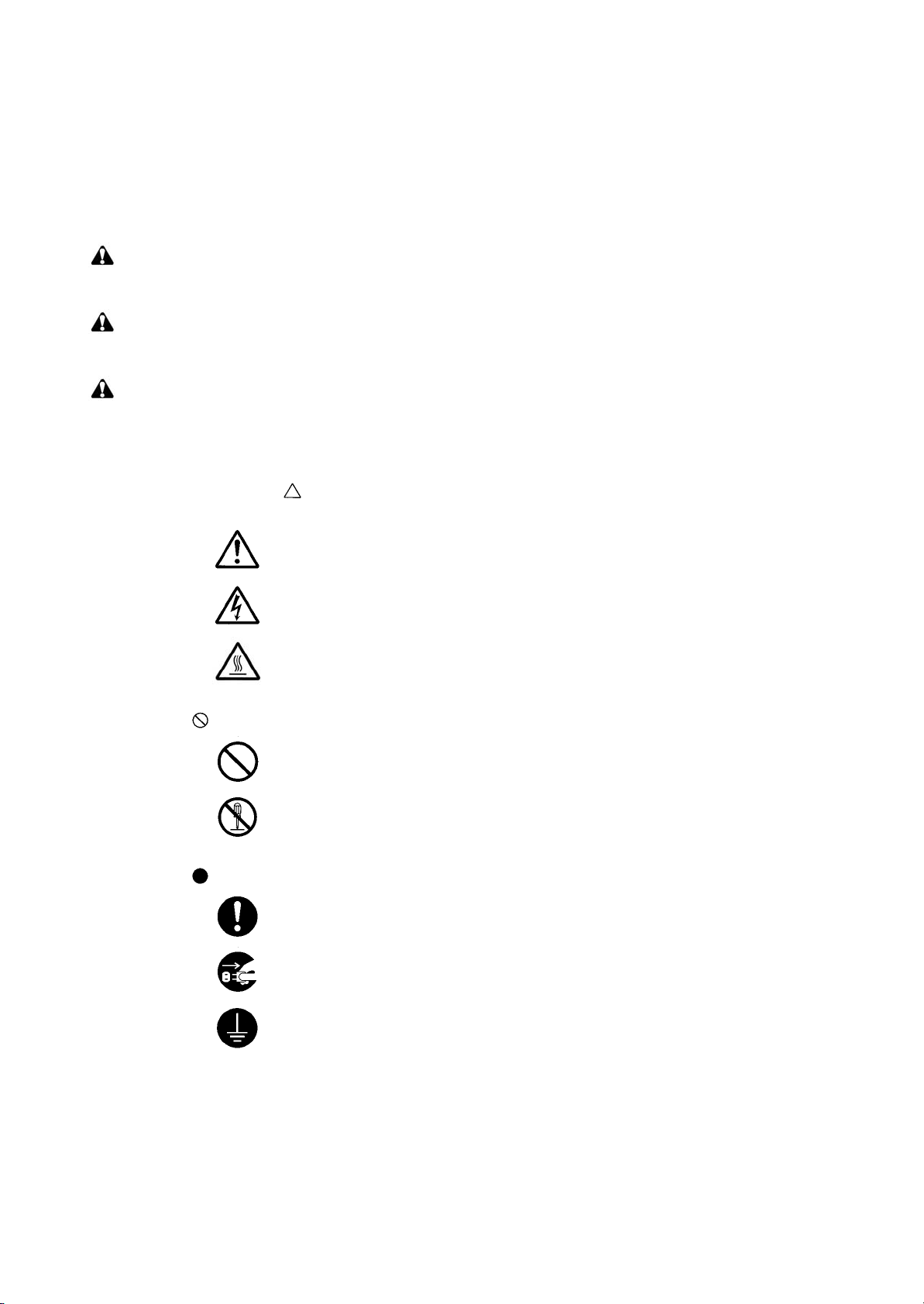
The triangle ( ) symbol indicates a warning including danger and caution. The specific point
of attention is shown inside the symbol.
General warning.
Warning of risk of electric shock.
Warning of high temperature.
indicates a prohibited action. The specific prohibition is shown inside the symbol.
General prohibited action.
Disassembly prohibited.
indicates that action is required. The specific action required is shown inside the symbol.
General action required.
Remove the power plug from the wall outlet.
Always ground the copier.

1.Installation Precautions
WARNING
• Do not use a power supply with a voltage other than that specified. Avoid multiple connections to
one outlet: they may cause fire or electric shock. When using an extension cable, always check
that it is adequate for the rated current. .............................................................................................
• Connect the ground wire to a suitable grounding point. Not grounding the copier may cause fire or
electric shock. Connecting the earth wire to an object not approved for the purpose may cause
explosion or electric shock. Never connect the ground cable to any of the following: gas pipes,
lightning rods, ground cables for telephone lines and water pipes or faucets not approved by the
proper authorities. ............................................................................................................................
CAUTION:
• Do not place the copier on an infirm or angled surface: the copier may tip over, causing injury. .......
• Do not install the copier in a humid or dusty place. This may cause fire or electric shock. ................
• Do not install the copier near a radiator, heater, other heat source or near flammable material.
This may cause fire. .........................................................................................................................
• Allow sufficient space around the copier to allow the ventilation grills to keep the machine as cool
as possible. Insufficient ventilation may cause heat buildup and poor copying performance. ...........
• Always handle the machine by the correct locations when moving it. ...............................................
• Always use anti-toppling and locking devices on copiers so equipped. Failure to do this may cause
the copier to move unexpectedly or topple, leading to injury. ...........................................................
• Avoid inhaling toner or developer excessively. Protect the eyes. If toner or developer is accidentally ingested, drink a lot of water to dilute it in the stomach and obtain medical attention immediately. If it gets into the eyes, rinse immediately with copious amounts of water and obtain medical
attention. ......................................................................................................................................
• Advice customers that they must always follow the safety warnings and precautions in the copier’s
instruction handbook. .....................................................................................................................
2.Precautions for Maintenance
WARNING
• Always remove the power plug from the wall outlet before starting machine disassembly. ...............
• Always follow the procedures for maintenance described in the service manual and other related
brochures. .......................................................................................................................................
• Under no circumstances attempt to bypass or disable safety features including safety mechanisms
and protective circuits. .....................................................................................................................
• Always use parts having the correct specifications. ..........................................................................
• Always use the thermostat or thermal fuse specified in the service manual or other related brochure when replacing them. Using a piece of wire, for example, could lead to fire or other serious
accident. ..........................................................................................................................................
• When the service manual or other serious brochure specifies a distance or gap for installation of a
part, always use the correct scale and measure carefully. ................................................................
• Always check that the copier is correctly connected to an outlet with a ground connection. .............
• Check that the power cable covering is free of damage. Check that the power plug is dust-free. If it
is dirty, clean it to remove the risk of fire or electric shock. ..............................................................
• Never attempt to disassemble the optical unit in machines using lasers. Leaking laser light may
damage eyesight. ...........................................................................................................................
• Handle the charger sections with care. They are charged to high potentials and may cause electric
shock if handled improperly. ............................................................................................................
CAUTION
• Wear safe clothing. If wearing loose clothing or accessories such as ties, make sure they are
safely secured so they will not be caught in rotating sections. ..........................................................
• Use utmost caution when working on a powered machine. Keep away from chains and belts. ........
• Handle the fixing section with care to avoid burns as it can be extremely hot. ..................................
• Check that the fixing unit thermistor, heat and press rollers are clean. Dirt on them can cause
abnormally high temperatures. ........................................................................................................
• Do not remove the ozone filter, if any, from the copier except for routine replacement. ....................
• Do not pull on the AC power cord or connector wires on high-voltage components when removing
them; always hold the plug itself. .....................................................................................................
• Do not route the power cable where it may be stood on or trapped. If necessary, protect it with a
cable cover or other appropriate item. .............................................................................................
• Treat the ends of the wire carefully when installing a new charger wire to avoid electric leaks. ........
• Remove toner completely from electronic components. ...................................................................
• Run wire harnesses carefully so that wires will not be trapped or damaged. ....................................
• After maintenance, always check that all the parts, screws, connectors and wires that were
removed, have been refitted correctly. Special attention should be paid to any forgotten connector,
trapped wire and missing screws. ...................................................................................................
• Check that all the caution labels that should be present on the machine according to the instruction
handbook are clean and not peeling. Replace with new ones if necessary. ......................................
• Handle greases and solvents with care by following the instructions below: .....................................
· Use only a small amount of solvent at a time, being careful not to spill. Wipe spills off completely.
· Ventilate the room well while using grease or solvents.
· Allow applied solvents to evaporate completely before refitting the covers or turning the power
switch on.
· Always wash hands afterwards.
• Never dispose of toner or toner bottles in fire. Toner may cause sparks when exposed directly to
fire in a furnace, etc. .......................................................................................................................
• Should smoke be seen coming from the copier, remove the power plug from the wall outlet imme-
diately. ............................................................................................................................................
3.Miscellaneous
WARNING
• Never attempt to heat the drum or expose it to any organic solvents such as alcohol, other than the
specified refiner; it may generate toxic gas. .....................................................................................

This page is intentionally left blank.

CONTENTS
1-1 Specifications
1-1-1 Specifications..........................................................................................................................................1-1-1
1-1-2 Parts names............................................................................................................................................1-1-3
(1) Overall ...............................................................................................................................................1-1-3
(2) Operation panel.................................................................................................................................1-1-4
1-1-3 Machine cross section ............................................................................................................................1-1-5
1-2 Installation
1-2-1 Drum unit ................................................................................................................................................1-2-1
1-2-2 Developer unit and toner container.........................................................................................................1-2-1
1-2-3 Installation environment ..........................................................................................................................1-2-1
1-2-4 Unpacking and installation ......................................................................................................................1-2-2
(1) Unpacking .........................................................................................................................................1-2-2
1-2-5 Installing the expanding memory (option) ...............................................................................................1-2-3
1-2-6 Installing the memory card (option).........................................................................................................1-2-4
1-2-7 Installing the hard disk (option) ...............................................................................................................1-2-5
1-3 Maintenance Mode
1-3-1 Maintenance mode .................................................................................................................................1-3-1
(1) Executing a maintenance item ..........................................................................................................1-3-1
(2) Contents of maintenance mode items...............................................................................................1-3-2
2J5-1
1-4 Troubleshooting
1-4-1 Paper misfeed detection .........................................................................................................................1-4-1
(1) Paper misfeed indication ...................................................................................................................1-4-1
(2) Paper misfeed detection....................................................................................................................1-4-1
1-4-2 Self-diagnostic function...........................................................................................................................1-4-2
(1) Self-diagnostic function .....................................................................................................................1-4-2
(2) Self diagnostic codes ........................................................................................................................1-4-2
1-4-3 Image formation problems ......................................................................................................................1-4-8
(1) Completely blank printout..................................................................................................................1-4-9
(2) All-black printout..............................................................................................................................1-4-10
(3) Dropouts..........................................................................................................................................1-4-11
(4) Black dots........................................................................................................................................1-4-11
(5) Black horizontal streaks. .................................................................................................................1-4-12
(6) Black vertical streaks.......................................................................................................................1-4-12
(7) Unsharpness. ..................................................................................................................................1-4-12
(8) Gray background.............................................................................................................................1-4-13
(9) Dirt on the top edge or back of the paper........................................................................................1-4-13
(10) Undulated printing at the left edge (scanning start position). ..........................................................1-4-13
1-4-4 Electric problems ..................................................................................................................................1-4-14
1-4-5 Mechanical problems ............................................................................................................................1-4-16
1-5 Assembly and Disassembly
1-5-1 Precautions for assembly and disassembly............................................................................................1-5-1
(1) Precautions .......................................................................................................................................1-5-1
(2) Drum..................................................................................................................................................1-5-1
(3) Toner container .................................................................................................................................1-5-1
(4) How to tell a genuine Kyocera Mita toner container ..........................................................................1-5-2
1-5-2 Outer covers ...........................................................................................................................................1-5-3
(1) Detaching and refitting the top cover.................................................................................................1-5-3
(2) Detaching and refitting the right cover and left cover........................................................................1-5-4
1-5-3 Paper feed section..................................................................................................................................1-5-5
(1) Detaching and refitting the paper feed assembly (paper feed roller and pickup roller).....................1-5-5
(2) Detaching and refitting the retard roller.............................................................................................1-5-6
(3) Detaching and refitting the registration upper and lower roller..........................................................1-5-7
(4) Detaching and refitting the MP tray paper feed roller........................................................................1-5-9
1-5-4 Developer section .................................................................................................................................1-5-11
(1) Detaching and refitting the developer unit .......................................................................................1-5-11

2J5-1
1-5-5 Drum section.........................................................................................................................................1-5-12
1-5-6 Transfer/separation section ..................................................................................................................1-5-14
1-5-7 Fuser section ........................................................................................................................................1-5-16
1-5-8 PWBs ....................................................................................................................................................1-5-23
1-5-9 Others ...................................................................................................................................................1-5-32
1-6 Firmware
1-6-1 Downloading firmware ............................................................................................................................1-6-1
(1) Detaching and refitting the drum unit ..............................................................................................1-5-12
(2) Detaching and refitting the main charger unit..................................................................................1-5-13
(1) Detaching and refitting the transfer roller and separation charger brush unit .................................1-5-14
(1) Detaching and refitting the fuser unit...............................................................................................1-5-16
(2) Detaching and refitting the fuser heater lamp M and S ...................................................................1-5-17
(3) Detaching and refitting the heat roller .............................................................................................1-5-19
(4) Detaching and refitting the press roller............................................................................................1-5-20
(5) Detaching and refitting the fuser thermistor M, fuser thermistor S and thermal cutout ...................1-5-21
(1) Detaching and refitting the engine PWB .........................................................................................1-5-23
(2) Detaching and refitting the main PWB ............................................................................................1-5-27
(3) Detaching and refitting the power source unit .................................................................................1-5-29
(1) Detaching and refitting the paper feed drive unit.............................................................................1-5-32
(2) Detaching and refitting the main drive unit ......................................................................................1-5-34
(3) Detaching and refitting the laser scanner unit.................................................................................1-5-35
(4) Direction of installing the principal fan motors.................................................................................1-5-36
(1) Downloading the firmware from the USB memory ............................................................................1-6-2
(2) Downloading the firmware from the memory card.............................................................................1-6-3
2-1 Mechanical Construction
2-1-1 Paper feed section..................................................................................................................................2-1-1
(1) Paper cassette paper feeding ...........................................................................................................2-1-1
(2) MP tray paper feed section ...............................................................................................................2-1-2
(3) Paper feed conveying section ...........................................................................................................2-1-3
2-1-2 Drum section...........................................................................................................................................2-1-4
(1) Drum section .....................................................................................................................................2-1-4
2-1-3 Expose section........................................................................................................................................2-1-5
(1) Laser scanner unit.............................................................................................................................2-1-5
2-1-4 Developing section..................................................................................................................................2-1-7
(1) Developer unit ...................................................................................................................................2-1-7
2-1-5 Transfer/separation section ....................................................................................................................2-1-8
(1) Transfer/separation section...............................................................................................................2-1-8
2-1-6 Cleaning section .....................................................................................................................................2-1-9
2-1-7 Fuser section ........................................................................................................................................2-1-10
(1) Fuser unit ........................................................................................................................................2-1-10
2-1-8 Paper exit section/rear unit ...................................................................................................................2-1-12
(1) Paper exit section/rear unit..............................................................................................................2-1-12
2-1-9 Duplex conveying section .....................................................................................................................2-1-14
(1) Duplex conveying section................................................................................................................2-1-14
2-2 Electrical Parts Layout
2-2-1 Electrical parts layout..............................................................................................................................2-2-1
(1) Electrical parts layout ........................................................................................................................2-2-1
2-3 Operation of the PWBs
2-3-1 Power source unit ...................................................................................................................................2-3-1
2-3-2 Engine PWB............................................................................................................................................2-3-3
2-4 Appendixes
Repetitive defects gauge ........................................................................................................................2-4-1
Wiring diagram........................................................................................................................................2-4-3

1-1 Specifications
1-1-1 Specifications
Printing method............................... Semiconductor laser and electrophotography
Printing speeds ...............................Simplex:
A4: 35 ppm
A5: 35 ppm
A3: 17 ppm
Duplex:
A4: 24.5 ppm
A5-R: 16 ppm
A3: 10.5 ppm
Paper sizes ..................................... Paper cassette:
Ledger, Legal, Letter, A3, A4, B4, A5, JIS B5, A5, A6, Folio, Oficio II, Statement,
Envelope C4, Envelope C5, ISO B5, Executive, 8 kai, 16 kai,
Custom (148 × 210 to 297 × 432 mm)
MP tray:
Ledger, Legal, Letter, A3, A4, B4, A5, JIS B5, A5, A6, Folio, Oficio II, Envelope,
Monarch, Envelope #10, Envelope DL, Statement, Envelope C4, Envelope C5,
ISO B5, Executive, Envelope #9, Envelope #6, Hagaki, Ofuku-Hagaki, 8 kai, 16 kai,
Yokei 2, Yokei 4, Custom (70 × 148 to 297 × 450 mm)
Paper types..................................... Paper cassette:
Plain, Preprinted, Bond, Recycled, Rough, Letterhead, Color (Colour),
Prepunched, High Quality, and Custom (1 to 8)
MP tray:
Plain, Transparency, Preprinted, Labels, Bond, Recycled, Rough, Vellum,
Letterhead, Color (Colour), Prepunched, Envelope, Cardstock, Thick paper,
High Quality, and Custom (1 to 8)
Resolution.......................................Fine 1200, Fast 1200 mode, 600 dpi, 300 dpi
Warm-up time (22 °C/71.6 °F, 60%RH)
First print out (A4) ...........................9 seconds or less when EcoFuser is Off and the printer is in Ready status.
Paper feed source capacity ............ Paper cassette: 250 sheets (80 g/m
Output ray capacity......................... Top tray: 250 sheets (80 g/m
Photo conductor.............................. a-Si (diameter: 30mm/1 3/16")
Charging system.............................Contact charger roller method (positive charging)
Developing system .........................Single component developer
Transfer system .............................. Transfer roller
Separation system ..........................Separation brush (DC bias)
Fixing System .................................Heat fusing with a heat roller and a press roller
Charge erasing system...................Light emitted by LED
Cleaning system ............................. Counter blade cleaning
Operating systems..........................Windows 2000 Service Pack 2 or later, Windows Server 2003, Windows XP,
Controller ........................................PowerPC440/600 MHz
Memory...........................................Standard: 128 MB
Interface..........................................Standard:
...Power on: 15 seconds or less
Sleep: 15 seconds or less
24 seconds or less when EcoFuser is On and the printer is in sleep mode.
2
MP tray: 100 sheets (80 g/m
2
2
Face up tray (optional): PT-430: 250 sheets (80 g/m
)
)
)
2
)
Windows Vista, Mac OS X 10.x
Maximum: 1152 MB
Parallel: 1 (IEEE1284)
Hi-Speed USB: 1
Network: 1(10BASE-T/100BASE-TX)
Full-speed USB: 1 (USB flash memory slot)
KUIO-LV(W) slot
2J5
1-1-1

2J5
Operation environment ................... Temperature: 10 to 32.5
Relative humidity: 15 to 80%
Altitude: 2,500 m/8,202 ft maximum
Illumination: 1,500 lux maximum
Dimensions (W × D × H) ................. 469 × 395 × 285 mm/18
Weight (without toner container).....19.5 kg/43 lbs
Power source..................................220-240 V, 50 Hz/60 Hz, max. 3.9 A (European countries) Max.
Allowable voltage fluctuation: ±10% Max.
Allowable frequency fluctuation:
Power consumption ........................ Maximum 976 W
During printing: 516 W
During standby: 9.6 W (EcoFuser: ON), 67 W (EcoFuser: OFF)
Power off: 0 W
°C/50 to 90.5°F
7/16 × 15 9/16 × 11 1/4"
±2%
1-1-2
1-1-2 Parts names
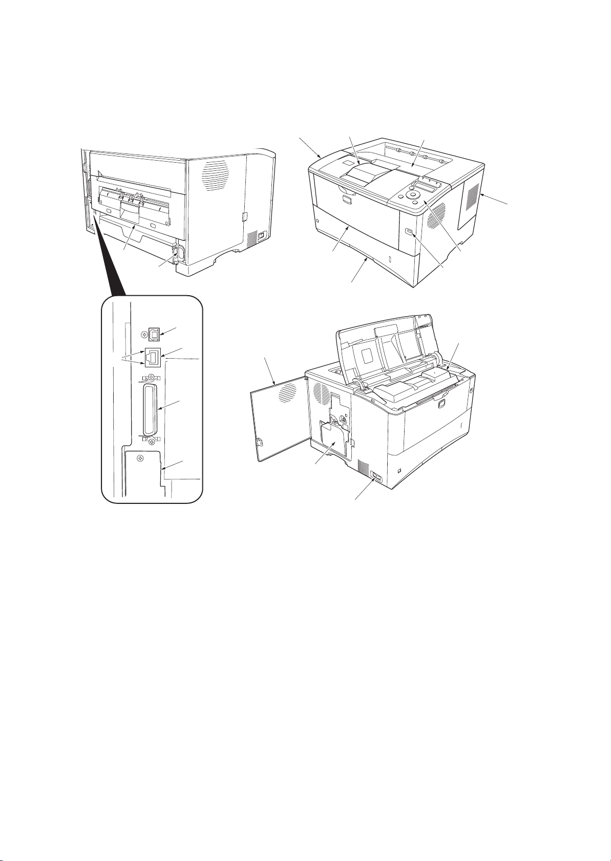
(1) Overall
2J5
14
19
18
13
16
15
1
9
2
8
7
3
4
5
6
10
17
1. Top cover
2. Paper stopper
3. Top tray
4. Right side cover
5. Operation panel
6. USB memory slot
7. Paper cassette
8. MP (Multi-Purpose) tray
9. Left side cover
10. Toner container
12
11
Figure 1-1-1
11. Power swi tch
12. Waste toner box
13. USB interface connector
14. Network indicators
15. Network interface connector
16. Parallel interface connector
17. Option interface slot
(Memory card/Hard disk)
18. AC inlet
19. Rear unit
1-1-3
2J5
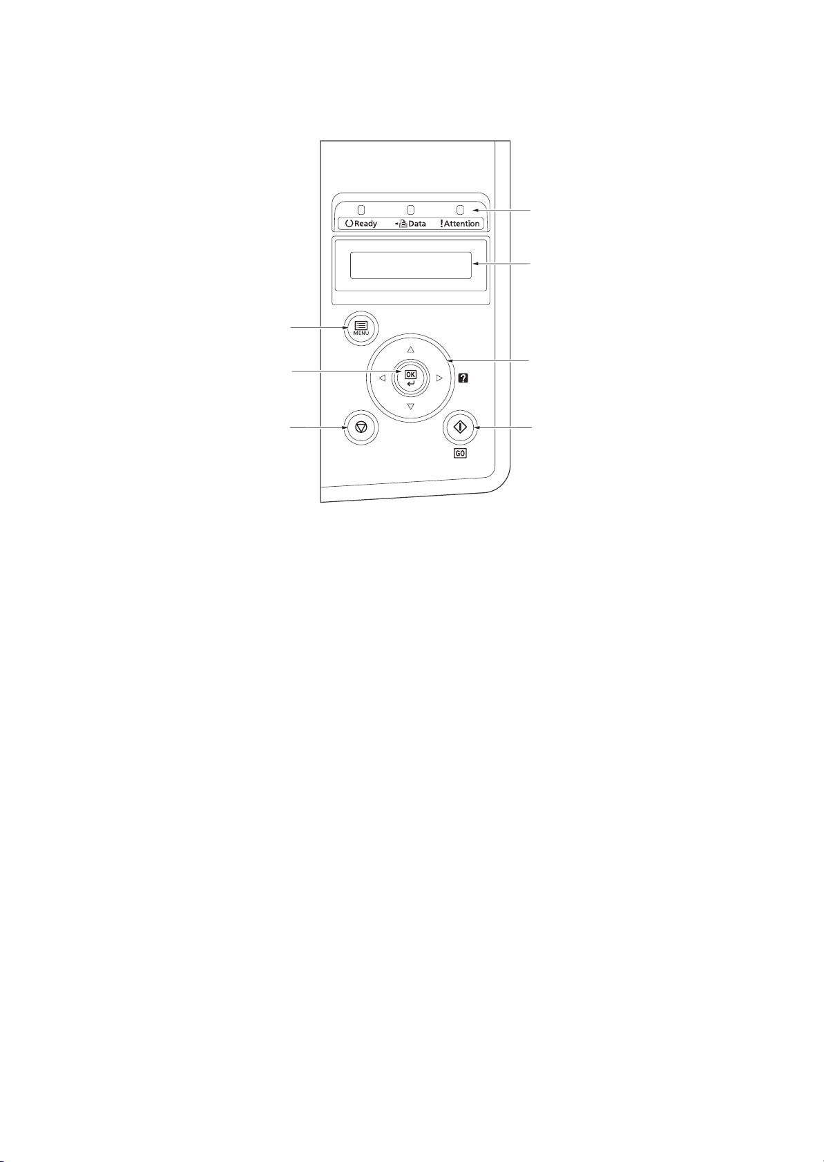
(2) Operation panel
1
2
7
6
3
45
Figure 1-1-2
1. Indicators
2. Message display
3. Cursor keys
4. GO Key
5. Cancel Key
6. OK Key
7. MENU Key
1-1-4
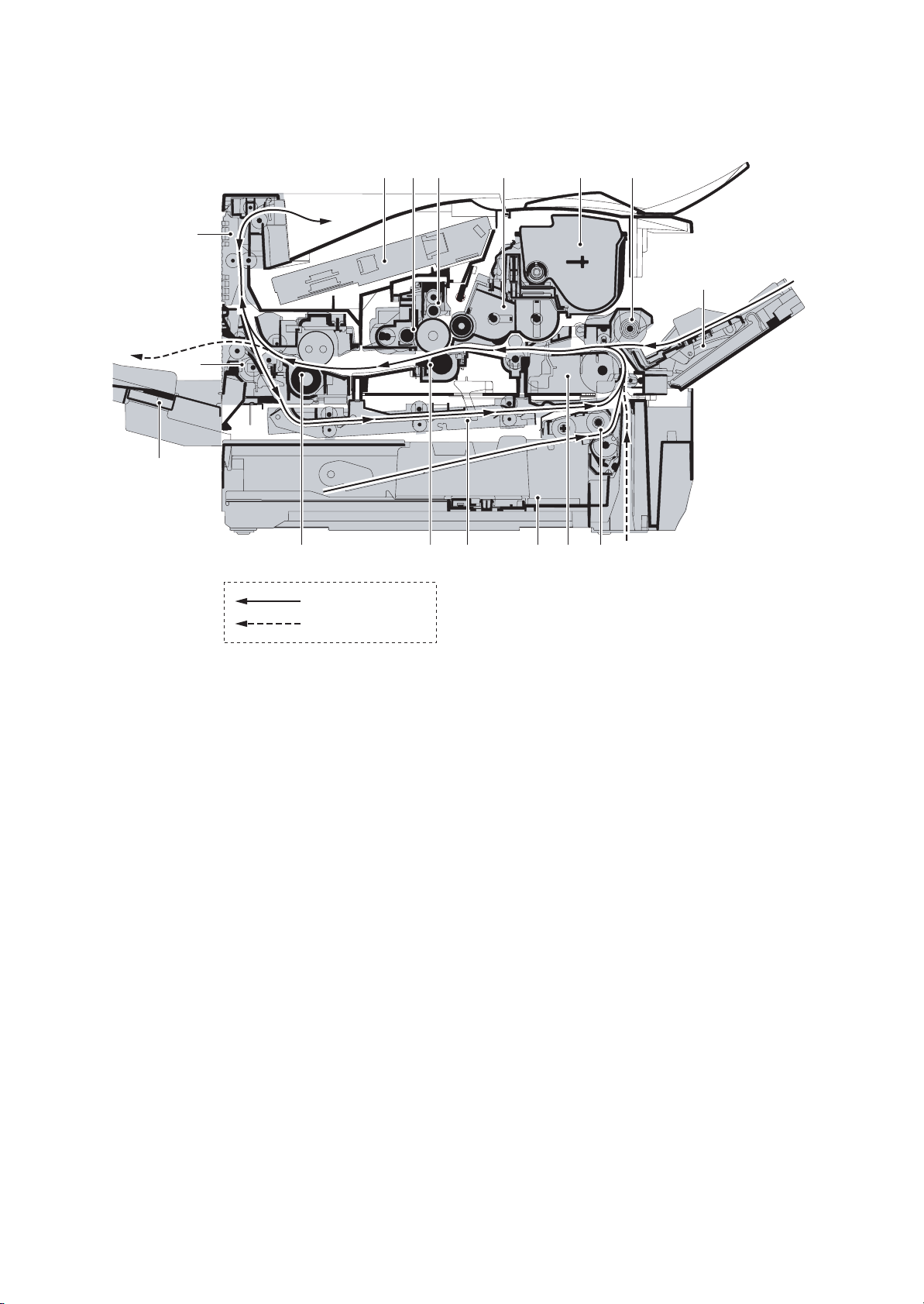
1-1-3 Machine cross section
2J5
Paper path
Paper path (optional)
Figure 1-1-3 Machine cross section
1. MP (Multi-Purpose) tray
2. MP tray paper feed unit
3. Toner container
4. Developer unit
5. Main charger unit
6. Drum unit
7. Laser scanner unit
8. Paper exit section
9. Rear unit
10. Fuser unit
11. Transfer/separation section
12. Duplex paper conveying section
13. Paper cassette
14. Paper conveying section
15. Paper cassette paper feed section
16. Face-up tray (optional)
1-1-5

2J5
This page is intentionally left blank.
1-1-6
1-2 Installation
1-2-1 Drum unit
Note the following when handling or storing the drum (drum unit).
Note the following when handling or storing the drum unit.
1. When removing the drum unit, never expose the drum surface to strong direct light.
2. Avoid abrupt changes in temperature and humidity.
3. Avoid exposure to any substance which is harmful to or may affect the quality of the drum.
4. Do not touch the drum surface with any object. Should it be touched by hands or stained with oil, clean it.
1-2-2 Developer unit and toner container
Store the toner container in a cool, dark place.
Avoid direct light and high humidity.
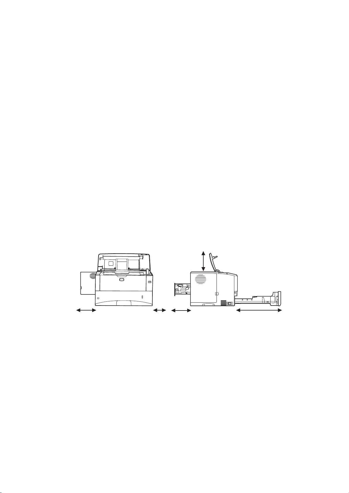
1-2-3 Installation environment
1. Temperature: 10 to 32.5°C/50 to 90.5°F
2. Humidity: 15 - 80%RH
3. Power supply: 220 - 240 V AC, 3.9 A
4. Power source frequency: 50 Hz ±0.3%/60 Hz ±0.3%
5. Installation location
Avoid direct sunlight or bright lighting. Ensure that the photoconductor will not be exposed to direct sunlight or
other strong light when removing paper jams.
Avoid locations subject to high temperature and high humidity or low temperature and low humidity; an abrupt
change in the environmental temperature; and cool or hot, direct air.
Avoid places subject to dust and vibrations.
Choose a surface capable of supporting the weight of the machine.
Place the machine on a level surface (maximum allowance inclination: 1
Avoid air-borne substances that may adversely affect the machine or degrade the photoconductor, such as mercury, acidic of alkaline vapors, inorganic gasses, NOx, SOx gases and chlorine-based organic solvents.
Select a well-ventilated location.
6. Allow sufficient access for proper operation and maintenance of the machine.
°).
2J5-1
Left: 300 mm
(11
13/16")
Right: 100 mm
(3
15/16")
Figure 1-2-1
Top: 300 mm
(11
13/16")
Rear: 200 mm
(7 7/8")
400 mm (15
when the optional
face up tray (PT-430)
is attached.
3/4" )
Front: 600 mm
(23
5/8")
1-2-1
2J5
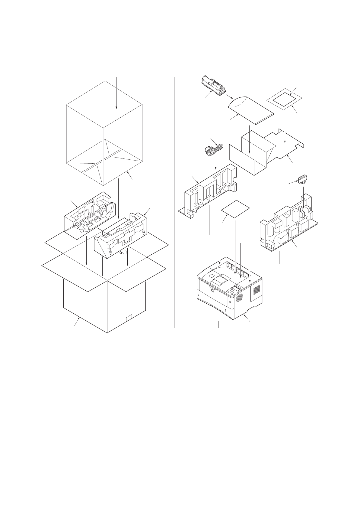
1-2-4 Unpacking and installation
(1) Unpacking
1-2-2
1. Printer
2. Outer case
3. Bottom pad L
4. Bottom pad R
5. Machine cover
6. Top pad L
7. Top pad R
8. Accessory spacer
Figure 1-2-2 Unpacking
9. Plastic bag
10. Installation guide etc.
11. Plastic bag
12. Toner container
13. Power cord
14. Waste toner box
15. Leaflet
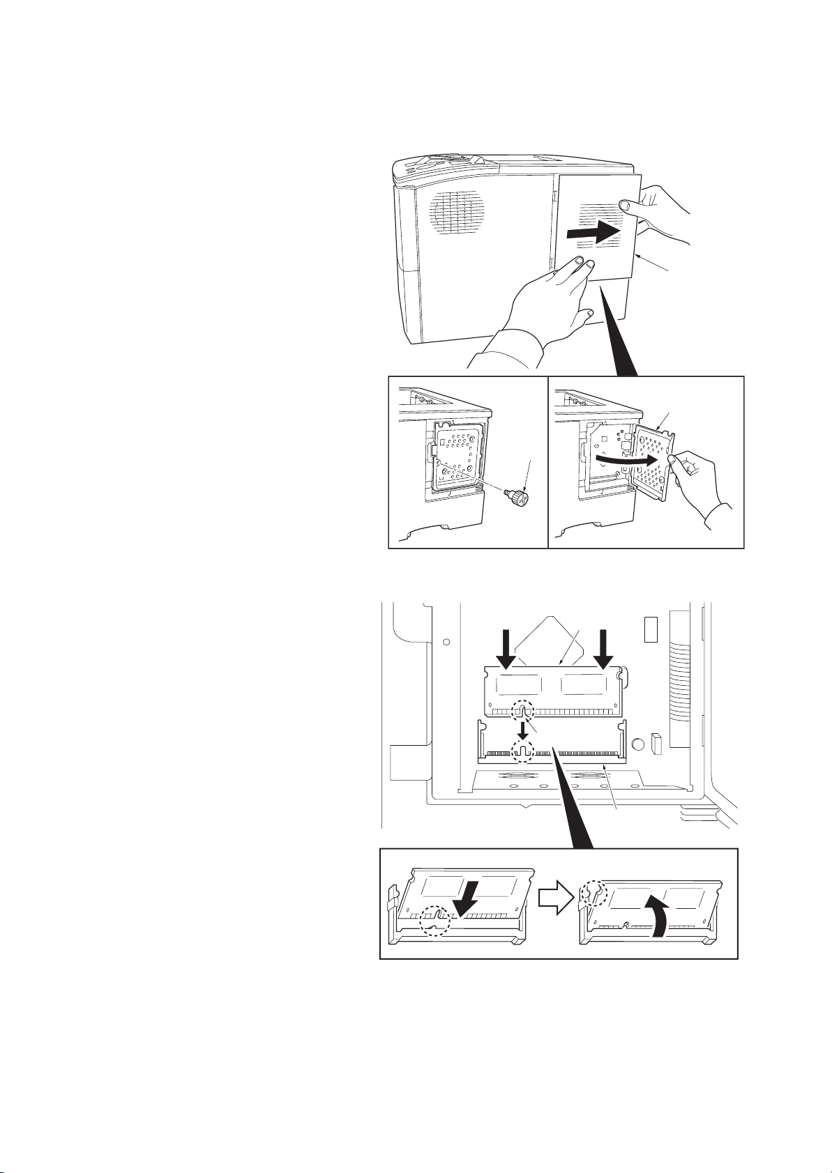
1-2-5 Installing the expanding memory (option)
<Procedure>
1. Power off the printer and unplug the printer
power cord.
2. Open the right side cover.
3. Remove the screw and open the inner
cover.
2J5
Right side cover
Inner cover
Screw
4. Aligning the cutouts of the memory module
with the matching keys of the socket, carefully plug the memory module into the memory socket until it clicks in place.
5. Then, push down the memory module to
secure.
6. Close and secure the inner cover by one
screw.
7. Refit the right side cover.
Verifying the expanded memory
1. To verify that the memory module is working
properly, test it by printing a status page.
Figure 1-2-3
Memory module
Cutout
Memory socket
Figure 1-2-4
1-2-3
2J5
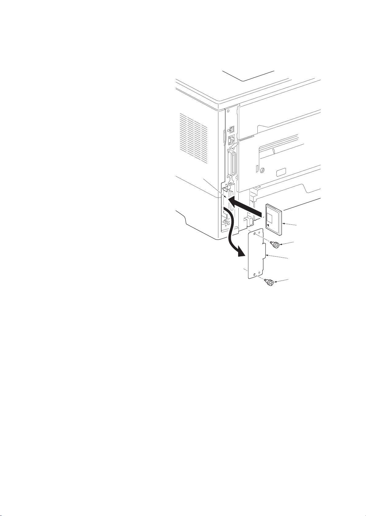
1-2-6 Installing the memory card (option)
<Procedure>
1. Turn off the printer and disconnect the
power cord and printer cable.
2. Remove two screws and then open the
option interface slot cover.
3. Install the memory card into the option inter-
face slot.
4. Refit the option interface slot cover by two
screws.
Memory card slot
Figure 1-2-5
Memory card
Screw
Option interface
slot cover
Screw
1-2-4
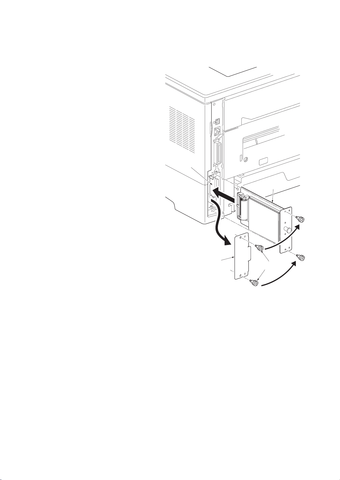
1-2-7 Installing the hard disk (option)
<Procedure>
1. Turn off the printer and disconnect the
power cord and printer cable.
2. Remove two screws and then open the
option interface slot cover.
3. Install the hard disk into the option interface
slot.
4. Refit the option interface slot cover by two
screws.
2J5
Hard disk
Option interface
slot cover
Screws
Figure 1-2-6
1-2-5

2J5
This page is intentionally left blank.
1-2-6
1-3 Maintenance Mode
1-3-1 Maintenance mode
The printer is equipped with a maintenance function which can be used to maintain and service the machine.
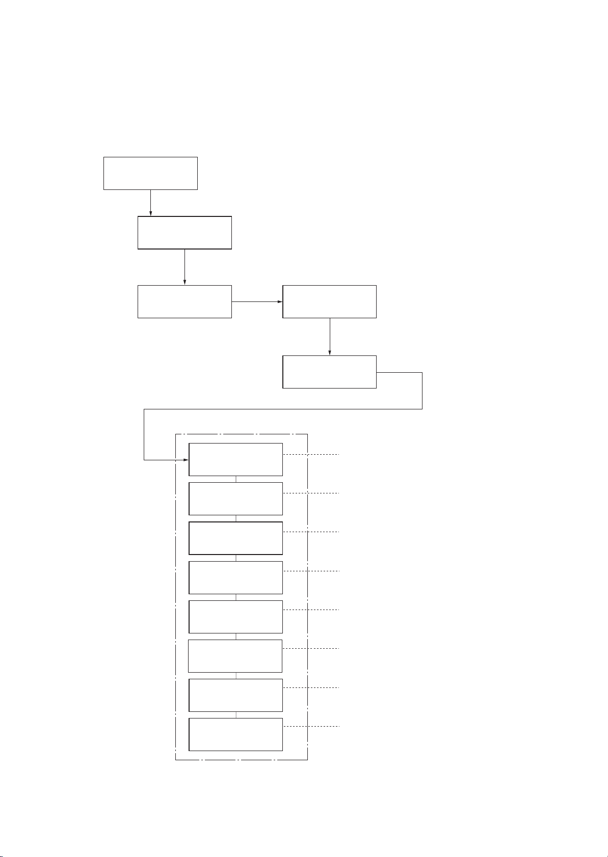
(1) Executing a maintenance item
Message display
Ready
Press the MENU key.
Report Print >
2J5
Press the or key several
until [Adjust/Maintenance >] is displayed.
Adjust/ >
Maintenance
Press the key.
Maintenance mode items
>>Print
Status Page
>>Print Network
Status Page
>>Print
Test Page
times
>Restart
Printer
Press the or key several times
until [>Service >] is displayed.
>Service >
Press the key.
To print a status page for service purpose.
(See page 1-3-2)
To print a network status page.
(See page 1-3-6)
Prints a test page which contains halftone.
(See page 1-3-7)
To scroll these
press the or key
repeatedly.
items,
>>Write Data
>>Maintenance
>>Developer
>>DRUM-CTRL
>>Drum
To write data into a USB memory.
(See page 1-3-7)
o reset counter for the maintenance kit.
T
(See page 1-3-8)
To initialize the developing unit. (toner install mode)
(See page 1-3-8)
To perform a automatic drum refreshing.
(See page 1-3-9)
To perform a drum refreshing.
(See page 1-3-9)
1-3-1
2J5-2
(2) Contents of maintenance mode items
Maintenance items Description
Printing a status page for service purpose
Description
>>Print
Status Page
Prints a status page for service purpose. The status page includes various printing settings
and service cumulative.
Purpose
To acquire the current printing environmental parameters and cumulative information.
Procedure
1. Enter the maintenance mode [>>Print Status Page].
2. Press the OK key. [Print Status Page?] will be displayed.
3. Press the OK key. Two pages will be printed.
Completion
Service Status Page
Printer
Firmware Version 2J5_2000.000.000
2009.01.27 [XXXXXXXX] [XXXXXXXX] [XXXXXXXX] [XXXXXXXX]
Controller Information
Memory Status
Standard Size
Option Slot
Total Size
Time
Local Time Zone
Time Server
Installed Options
Paper feeder 2
Paper feeder 3
Memory Card
Hard Disk
Digital Dot Coverage
Average (%) / Usage Page (A4/Letter Conversion)
K: 1.00 / 1111111.0 0
Last page (%) 1.00
FRPO Status
Default Pattern Switch
Default Font NumberB8C5*10000+C2*100+C3000000
500.0 KB
500.0 KB
1000.0 KB
+01:00 Amsterdam
10. 183. 53. 13
Installed
Installed
Installed
Installed
e-MPS error control Y6 0
1-3-2
1
Figure 1-3-1Service status page (1)
[XXXXXXXXXXXXXXXX]
Maintenance items Description
Service Status Page
Printer
2J5-2
Firmware Version 2J5_2000.000.000 [XXXXXXXX] [XXXXXXXX] [XXXXXXXX] [XXXXXXXX]
2009.01.27
Engine Information
NVRAM Version
MAC Address
1/2
100/100
0/0/0/0/0/0/0/
0/0/0/0/0/0/0/
0/0/0/0/0/0/0/0/
0000000/0000000/0000000/0000000/0000000/0000000/0000000/0000000/
0000000/0000000/
F00/U00/0/0/0/0/70/00/00/00/00/abcde/1/
0000/0000/0000/0000/0000/0000/0000/0000/0000/0000/0000/0000/0000/0000/0000/
0000/0000/0000/0000/0000/0000/0000/0000/0000/0000/
0203040508090A0B0C0D0F101112131415161718191A1B1C1D1E1F202122235E
12345678/11223344/00001234abcd567800001234abcd5678/01234567890123456789012345678901/0008/00/07
XXXXXXXX/t/
FFFFFFFFFFFFFFFF/FFFFFFFFFFFFFFFF/FFFFFFFFFFFFFFFF/FFFFFFFFFFFFFFFF/
FFFFFFFFFFFFFFFF/FFFFFFFFFFFFFFFF/FFFFFFFFFFFFFFFF/FFFFFFFFFFFFFFFF/
FFFFFFFFFFFFFFFF/FFFFFFFFFFFFFFFF/FFFFFFFFFFFFFFFF/FFFFFFFFFFFFFFFF/
FFFFFFFFFFFFFFFF/FFFFFFFFFFFFFFFF/FFFFFFFFFFFFFFFF/FFFFFFFFFFFFFFFF/
FFFFFFFFFFFFFFFF/FFFFFFFFFFFFFFFF/FFFFFFFFFFFFFFFF/FFFFFFFFFFFFFFFF/
FFFFFFFFFFFFFFFF/FFFFFFFFFFFFFFFF/FFFFFFFFFFFFFFFF/FFFFFFFFFFFFFFFF/
FFFFFFFFFFFFFFFF/FFFFFFFFFFFFFFFF/FFFFFFFFFFFFFFFF/FFFFFFFFFFFFFFFF/
FFFFFFFFFFFFFFFF/FFFFFFFFFFFFFFFF/FFFFFFFFFFFFFFFF/FFFFFFFFFFFFFFFF/
/00/
/00000000000000000000000000000000/00000000000000000000000000000000
/0000000000000000000000000000000000000000000000000000000000000000
/00000000/00000000/00000000/00000000/00000000/00000000/00000000/00000000/00000000/00000000/
/00000000/00000000/00000000/00000000/00000000/00000000/00000000/00000000/00000000/00000000/
/00000000/00000000/00000000/00000000/00000000/00000000/00000000/00000000/00000000/00000000/
/00000000/00000000/00000000/00000000/00000000/00000000/00000000/00000000/00000000/00000000/
/00000000/00000000/00000000/00000000/00000000/00000000/00000000/00000000/00000000/00000000/
/00000000/00000000/00000000/00000000/00000000/00000000/00000000/00000000/00000000/00000000/
/00000000/00000000/00000000/00000000/00000000/00000000/00000000/00000000/00000000/00000000/
/00000000/00000000/00000000/00000000/00000000/00000000/00000000/00000000/00000000/00000000/
/00000000/00000000/00000000/00000000/00000000/00000000/00000000/00000000/00000000/00000000/
/00000000/00000000/00000000/00000000/00000000/00000000/00000000/00000000/00000000/00000000/
/00000000/00000000/00000000/00000000/00000000/00000000/00000000/00000000/00000000/00000000/
/00000000/00000000/00000000/00000000/00000000/00000000/00000000/00000000/00000000/00000000/
/00000000/00000000/00000000/00000000/00000000/00000000/00000000/00000000/00000000/00000000/
/00000000/00000000/00000000/00000000/00000000/00000000/00000000/00000000/00000000/00000000/
/00000000/00000000/00000000/00000000/00000000/00000000/00000000/00000000/00000000/00000000/
/00000000/00000000/00000000/00000000/00000000/00000000/00000000/00000000/00000000/00000000/
/00000000/00000000/00000000/00000000/00000000/00000000/00000000/00000000/00000000/00000000/
/00000000/00000000/00000000/00000000/00000000/00000000/00000000/00000000/00000000/00000000/
/00000000/00000000/00000000/00000000/00000000/00000000/00000000/00000000/00000000/00000000/
/00000000/00000000/00000000/00000000/00000000/00000000/00000000/00000000/00000000/00000000/
/00000000/00000000/00000000/00000000/00000000/00000000/00000000/00000000/00000000/00000000/
/00000000/00000000/00000000/00000000/00000000/00000000/00000000/00000000/00000000/00000000/
/00000000/00000000/00000000/00000000/00000000/00000000/00000000/00000000/00000000/00000000/
[ABCDEFGHIJ][ABCDEFGHIJ][ABCDEFGHIJ][ABCDEFGHIJ]
[ABCDEFGHIJ][ABCDEFGHIJ][ABCDEFGHIJ][ABCDEFGHIJ]
ABCD/ABCDEFGHIJ/
_1F31225_1F31225
00:00:00:00:00:00
2
[XXXXXXXXXXXXXXXX]
Figure 1-3-2Service status page (2)
1-3-3
2J5-2
Maintenance items Description
Detail of service status page
No. Items Description
Firmware version
Engine software version -
Engine boot version -
Main ROM version
Panel mask version -
Used memory -
Local time zone -
Digital Dot Coverage Number of pages printed converted in reference to A4 or Letter size.
FRPO settings -
Machine serial No. -
NVRAM version _ 1F3 1225 _ 1F3 1225
-
-
(a) (b) (c) (d) (e) (f)
a) Consistency of the present software version and the database
_ (underscore): OK
* (Asterisk): NG
(b) Database version
(c) The oldest time stamp of database version
(d) Consistency of the present software version and the ME firmware version
_ (underscore): OK
* (Asterisk): NG
(e) ME firmware version
(f) The oldest time stamp of the ME database version
Normal if (a) and (d) are underscored, and (b) and (e) are identical with (c)
and (f).
Mac address -
Destination information -
Area information -
Margin settings Top margin/Left margin
Top offset for each paper
source
Left offset for each paper
source
L value settings Top margin (integer)/Top margin (decimal place)/Left margin (integer)/Left
MP tray/Paper feeder 1/Paper feeder 2/Paper feeder 3/
Paper feeder 4/Duplex/Page rotation
MP tray/Paper feeder 1/Paper feeder 2/Paper feeder 3/
Paper feeder 4/Duplex/Page rotation
margin (decimal place)/Paper length (integer)/Paper length (decimal place)/
Paper width (integer)/Paper width (decimal place)
1-3-4
Maintenance items Description
No. Items Description
Life counter (The first line)
Machine/MP tray/Printer cassette/Paper feeder 1/Paper feeder 2/
Paper feeder 3/Paper feeder 4/Duplex printing
2J5-2
Life counter (The second
line)
Operation panel lock status 0: Off
USB information 0: Not connected
Paper handling information 0: Paper source unit select
Black and white printing
double count mode
Billing counting timing -
Temperature (machine out-
side)
Relative temperature
(machine outside)
Absolute temperature
(machine outside)
XLI calibration information -
Fixed asset number -
Drum unit/Maintenance kit/
1: Partial lock
2: Full lock
1: Full-Speed
2: Hi-Speed
1: Paper source unit
0: All single counts
3: Folio, Single count, Less the 330 mm (length)
-
-
-
Laser beam-B BD synchro-
nization exact adjustment
value
Laser beam-B BD synchro-
nization exact adjustment
value
Setting at JOB end judg-
ment time-out time in local
IF
Media type attributes
1 to 28 (Not used: 18, 19,
20)
-
-
-
Weight settings
0: Light
1: Normal 1
2: Normal 2
3: Normal 3
4: Heavy 1
5: Heavy 2
6: Heavy 3
7: Extra Heavy
Fuser settings
0: High
1: Middle
2: Low
3: Vellum
Duplex settings
0: Disable
1: Enable
1-3-5
2J5-2
Maintenance items Description
No. Items Description
SPD information -
RFID information -
RFID reader/writer version infor-
mation
Toner install information 0: Off
Engine parameter information Hexadecimal, 512 bytes
Drum status -
Drum surface potential -
Drum sensitivity -
Quantity of light -
DRT parameter coefficient -
Optional paper feeder software
version
Optional font version -
Optional table version -
Optional message version -
Optional WEB version -
Drum ID -
Drum serial number -
NOTE:
Code conversion
-
t: On
Paper feeder 1/Paper feeder 2/Paper feeder 3/Paper feeder 4
>>Print Network
Status Page
ABCDEFGH I J
0123456789
Printing a status page for network
Description
On the status page for network, detailed network setting information is printed.
Procedure
1. Enter the maintenance mode [>>Print Network Status Page].
2. Press the OK key. [>>Print Network Status Page?] will be displayed.
3. Press the OK key. Three sheets of network status page will be printed.
Completion
1-3-6
 Loading...