

Page 1

FS-6950DN
SERVICE
MANUAL
Published in January 2006
842F7110
2F7SM060
First Edition
Page 2

Revision history
Revision Date Replaced pages Remarks
Page 3

Safety precautions
This booklet provides safety warnings and precautions for our service personne l to ensure the safety of
their customers, their machines as well as themselves during maintenance activities. Service personnel
are advised to read this booklet carefully to familiarize themselves with the warnings and precautions
described here before engaging in maintenance activities.
Page 4
Safety warnings and precautions
Various symbols are used to protect our service personnel and customers from physical danger and
to prevent damage to their property. These symbols are described below:
DANGER: High risk of serious bodily injury or death may result from insufficient attention to or incorrect
compliance with warning messages using this symbol.
WARNING: Serious bodily injury or death may result from insufficient attention to or incorrect compliance
with warning messages using this symbol.
CAUTION: Bodily injury or damage to property may result from insufficient attention to or incorrect
compliance with warning messages using this symbol.
Symbols
The triangle ( ) symbol indicates a warning including danger and caution. The specific point
of attention is shown inside the symbol.
General warning.
Warning of risk of electric shock.
Warning of high temperature.
indicates a prohibited action. The specific prohibition is shown inside the symbol.
General prohibited action.
Disassembly prohibited.
indicates that action is required. The specific action required is shown inside the symbol.
General action required.
Remove the power plug from the wall outlet.
Always ground the copier.
Page 5

1.Installation Precautions
WARNING
• Do not use a power supply with a voltage other than that specified. Avoid multiple connections to
one outlet: they may cause fire or electric shock. When using an extension cable, always check
that it is adequate for the rated current. .............................................................................................
• Connect the ground wire to a suitab le g rou nd ing point . No t g roun ding the co pier may cause fir e o r
electric shock. Connecting the earth wire to an object not approved for the purpose may cause
explosion or electric shock. Never connect the ground cable to any of the following: gas pipes,
lightning rods, ground cables for telephone lines and water pipes or faucets not approved by the
proper authorities. ............................................................................................................................
CAUTION:
• Do not place the copier on an infirm or angled surface: the copier may tip over, causing injury. .......
• Do not install the copier in a humid or dusty place. This may cause fire or electric shock. ................
• Do not install the copier near a radiator, heater, other heat source or near flammable material.
This may cause fire. .........................................................................................................................
• Allow sufficient space around the copier to allow the ventilation grills to keep the machine as cool
as possible. Insufficient ventilation may cause heat buildup and poor copying performance. ...........
• Always handle the machine by the correct locations when moving it. ...............................................
• Always use anti-toppling and locking devices on copiers so equipped. Failure to do this may cause
the copier to move unexpectedly or topple, leading to injury. ...........................................................
• Avoid inhaling toner or developer excessively. Protect the eyes. If toner or developer is accidentally ingested, drink a lot of water to dilute it in the stomach and obtain medical attention immediately. If it gets into the eyes, rinse immediately with copious amounts of water and obtain medical
attention. ......................................................................................................................................
• Advice customers that they must always follow the safety warnings and precautions in the copier’s
instruction handbook. .....................................................................................................................
Page 6
2.Precautions for Maintenance
WARNING
• Always remove the power plug from the wall outlet before starting machine disassembly. ...............
• Always follow the procedures for maintenance described in the service manu al and other related
brochures. ....................................... ... ... ... .... ... .......................................... ... ... .... ............................
• Under no circumstances attempt to bypass or disable safety features in cluding safety mechanisms
and protective circuits. .......................................... .... ... ... ... .......................................... ... .................
• Always use parts having the correct specifications. ..........................................................................
• Always use the thermostat or thermal fuse specified in the service manual or other related brochure when replacing them. Using a piece of wire, for example, could lead to fire or other serious
accident. ..........................................................................................................................................
• When the service manual or other serious brochure specifies a distance or ga p for inst alla tion of a
part, always use the correct scale and measure carefully. ................................................................
• Always check that the copier is correctly connected to an outlet with a ground connection. .............
• Check that the power cable covering is free of damage. Check that the power plug is dust-free. If it
is dirty, clean it to remove the risk of fire or electric shock. ..............................................................
• Never attempt to disassemble the optical unit in machines using lasers. Leaking laser light may
damage eyesight. ....................................... ... .... ... ... ... ... .... ... ... .......................................................
• Handle the charger sections with care. They are charged to high potentials and may cause electric
shock if handled improperly. ............................................................................................................
CAUTION
• Wear safe clothing. If wearing loose clothing or accessories such as ties, make sure they are
safely secured so they will not be caught in rotating sections. ..........................................................
• Use utmost caution when working on a powered machine. Keep away from chains and belts. ........
• Handle the fixing section with care to avoid burns as it can be extremely hot. ..................................
• Check that the fixing unit thermistor, heat and press rollers are clean. Dirt on them can cause
abnormally high temperatures. ........................................................................................................
Page 7
• Do not remove the ozone filter, if any, from the copier except for routine replacement. ....................
• Do not pull on the AC power cord or connector wires on high-voltage components when removing
them; always hold the plug itself. ................................ ... .... ... ... ... .... ... ..............................................
• Do not route the power cable where it may be stood on or trapped. If necessary, protect it with a
cable cover or other appropriate item. .............................................................................................
• Treat the ends of the wire carefully when installing a new charger wire to avoid electric leaks. ........
• Remove toner completely from electronic components. ...................................................................
• Run wire harnesses carefully so that wires will not be trapped or damaged. ....................................
• After maintenance, always check that all the parts, screws, connectors and wires that were
removed, have been refitted correctly. S pecial atte ntion shou ld be p aid to an y forgot ten connector,
trapped wire and missing screws. ...................................................................................................
• Check that all the caution labels that should be present on the machine according to the instruction
handbook are clean and not peeling. Replace with new ones if necessary . ......................................
• Handle greases and solvents with care by following the instructions below: .....................................
Use only a small amount of solvent at a time, being careful not to spill. Wipe spills off completely.
Ventilate the room well while using grease or solvents.
Allow applied solvents to evaporate completely before refitting the covers or turning the power switch on.
Always wash hands afterwards.
• Never dispose of toner or toner bottles in fire. Toner may cause sparks when exposed directly to
fire in a furnace, etc. .......................................................................................................................
• Should smoke be seen coming from the copier, remove the power plug from the wall outlet imme-
diately. ............................................................................................................................................
3.Miscellaneous
WARNING
• Never attempt to heat the drum or expose it to any organic solvents such as alcohol, other than the
specified refiner; it may generate toxic gas. .....................................................................................
Page 8

This page is intentionally left blank.
Page 9

CONTENTS
1-1 Specifications
1-1-1 Specifications..........................................................................................................................................1-1-1
1-1-2 Parts names............................................................................................................................................1-1-3
(1) Overall...............................................................................................................................................1-1-3
(2) Operation panel.......................................................... ... ....................................................................1-1-4
1-1-3 Machine cross section ............................................................................................................................1-1-5
1-2 Installation
1-2-1 Installation environment..........................................................................................................................1-2-1
1-2-2 Unpacking and installation......................................................................................................................1-2-2
(1) Installation procedure........................................................................................................................1-2-2
1-2-3 Installing the expanding memory (optional) ..........................................................................................1-2-10
1-2-4 Installing the memory card or hard disk (optional)................................................................................1-2-11
1-2-5 Installing the network interface card (optional) .....................................................................................1-2-12
1-3 Maintenance Mode
1-3-1 Maintenance mode .................................................................................................................................1-3-1
(1) Executing a maintenance item..........................................................................................................1-3-1
1-4 Troubleshooting
1-4-1 Paper misfeed detection.........................................................................................................................1-4-1
(1) Paper misfeed indication............................................ ... .. ........................................ ..........................1-4-1
(2) Paper misfeed detection....................................................................................................................1-4-1
1-4-2 Self-diagnostic function...........................................................................................................................1-4-2
(1) Self-diagnostic function.....................................................................................................................1-4-2
(2) Self diagnostic codes ........................................................................................................................1-4-2
1-4-3 Image formation problems......................................................................................................................1-4-8
(1) Completely blank printout..................................................................................................................1-4-9
(2) All-black printout..............................................................................................................................1-4-10
(3) Dropouts..........................................................................................................................................1-4-11
(4) Black dots........................................................................................................................................1-4-11
(5) Black horizontal streaks..................................................................................................................1-4-12
(6) Black vertical streaks.......................................................................................................................1-4-12
(7) Unsharpness...................................................................................................................................1-4-12
(8) Gray background........................................................... ..................................................................1-4-13
(9) Dirt on the top edge or back of the paper........................................................................................1-4-13
(10) Undulated printing at the left edge (scanning start position)...........................................................1-4-13
1-4-4 Electric problems ..................................................................................................................................1-4-14
1-4-5 Mechanical problems............................................................................................................................1-4-16
1-5 Assembly and Disassembly
1-5-1 Precautions for assembly and disassembly............................................................................................1-5-1
(1) Precautions .......................................................................................................................................1-5-1
1-5-2 Outer covers ...........................................................................................................................................1-5-2
(1) Detaching and refitting the top cover.................................................................................................1-5-2
(2) Detaching and refitting the right cover and left cover........................................................................1-5-3
1-5-3 Paper feed section..................................................................................................................................1-5-4
(1) Detaching and refitting the paper feed assembly (paper feed roller and pickup roller).....................1-5-4
(2) Detaching and refitting the retard roller.................................... ... .................................... ... ...............1-5-5
(3) Detaching and refitting the registration upper and lower roller..........................................................1-5-6
(4) Detaching and refitting the MP tray paper feed roller........................................................................1-5-8
1-5-4 Developer section...................................................................................................................................1-5-9
(1) Detaching and refitting the developer unit.........................................................................................1-5-9
1-5-5 Drum section.........................................................................................................................................1-5-10
(1) Detaching and refitting the drum unit ..............................................................................................1-5-10
(2) Detaching and refitting the main charger unit..................................................................................1-5-11
1-5-6 Transfer section.............................................. ... ...................................................................................1-5-12
(1) Detaching and refitting the transfer roller........................................................................................1-5-12
1-5-7 Fuser section ................................................................ ... .................................... ... ..............................1-5-14
(1) Detaching and refitting the fuser unit...............................................................................................1-5-14
(2) Detaching and refitting the fuser heater lamp M and S...................................................................1-5-15
(3) Detaching and refitting the heat roller .............................................................................................1-5-17
(4) Detaching and refitting the press roller................. ..................................... .. ....................................1-5-18
(5) Detaching and refitting the fuser thermistor M, fuser thermistor S and thermal cutout...................1-5-19
1-5-8 PWBs....................................................................................................................................................1-5-21
(1) Detaching and refitting the engine PWB .........................................................................................1-5-21
(2) Detaching and refitting the main PWB ............................................................................................1-5-25
Page 10

(3) Detaching and refitting the power source unit.................................................................................1-5-27
1-5-9 Others...................................................................................................................................................1-5-29
(1) Detaching and refitting the paper feed drive unit.............................................................................1-5-29
(2) Detaching and refitting the main drive unit......................................................................................1-5-30
(3) Detaching and refitting the laser scanner unit.................................................................................1-5-31
1-6 Firmware
1-6-1 Downloading firmware ............................................................................................................................1-6-1
(1) Downloading the firmware from the parallel interface .......................................................................1-6-2
(2) Downloading the firmware from the memory card..................................................... ........................1-6-3
(3) Downloading the firmware from the USB memory ............................................................. ...............1-6-5
2-1 Mechanical construction
2-1-1 Paper feed section..................................................................................................................................2-1-1
(1) Paper cassette paper feeding...........................................................................................................2-1-1
(2) MP tray paper feed section ...............................................................................................................2-1-2
(3) Paper feed conveying section...........................................................................................................2-1-3
2-1-2 Drum section...........................................................................................................................................2-1-4
(1) Drum section.....................................................................................................................................2-1-4
2-1-3 Expose section........................................................................................................................................2-1-5
(1) Laser scanner unit.............................................................................................................................2-1-5
2-1-4 Developing section..................................................................................................................................2-1-7
(1) Developer unit................................... .................................... ... .........................................................2-1-7
2-1-5 Transfer/separation section ....................................................................................................................2-1-8
(1) Transfer/separation section....................................................................................... ........................2-1-8
2-1-6 Cleaning section .....................................................................................................................................2-1-9
2-1-7 Fuser section ................................................................ ... .................................... ... ..............................2-1-10
(1) Fuser unit ........................................................................................................................................2-1-10
2-1-8 Paper exit section/rear unit...................................................................................................................2-1-12
(1) Paper exit section/rear unit..............................................................................................................2-1-12
2-1-9 Duplex conveying section.....................................................................................................................2-1-14
(1) Duplex conveying section................................................................................................................2-1-14
2-2 Electrical Parts Layout
2-2-1 Electrical parts layout ..............................................................................................................................2-2-1
(1) Electrical parts layout........................................................................................................................2-2-1
2-3 Operation of the PWBs
2-3-1 Power source unit...................................................................................................................................2-3-1
2-3-2 Engine PWB............................................................................................................................................2-3-3
2-3-3 Main PWB...............................................................................................................................................2-3-8
(1) Wiring diagram..................................................................................................................................2-4-1
(2) Repetitive defects gauge...................................................................................................................2-4-2
Page 11

1-1 Specifications
1-1-1 Specifications
Printing method...............................Semiconductor laser and electrophotography
Printing speeds...............................Simplex:
A3: 16 ppm
A4: 32 ppm
A5: 32 ppm
Duplex:
A3: 10 ppm
A4: 23 ppm
Paper sizes.....................................Paper cassette:
A3, A4, A5, B4, B5, ledger, letter, legal, envelope C4, envelope C5, ISO B5,
executive, oficio II, 8 kai, 16 kai, folio, and custom
MP tray:
A3, A4, A5, A6, B4, B5, B6, ledger, letter, legal, envelope monarch, envelope DL,
envelope C4, envelope C5, ISO B5, executive, envelope # 6, envelope # 9,
envelope # 10, hagaki, oufuku hagaki, oficio II, 8 kai, 16 kai, statement, folio,
yokei 2, yokei 4, and custom
Paper types.....................................Paper cassette:
Plain, preprinted, bond, recycled, rough, letterhead, color, prepunched, high quality,
and custom
MP tray:
Plain, transparency, preprinted, labels, bond, recycled, vellum, rough, letterhead,
color, prepunched, envelope, cardstock, thick, high quality, and custom
Paper feed source capacity............Paper cassette: 250 sheets (80 g/m
MP tray: 100 sheets (80 g/m
Output ray capacity.........................Top tray: 250 sheets (80 g/m
Face up tray (optional): PT-430: 250 sheets (80 g/m
Photo conductor..............................a-Si (diameter: 30mm)
Charging system.............................Contact charger roller method (positive charging)
Developing system .........................Single component developer
Transfer system..............................Transfer roller
Separation system..........................Separation brush (DC bias)
Fixing System.................................Heat fusing with a heat roller and a press roller
Charge erasing system...................Light emitted by LED
Cleaning system.............................Counter blade cleaning
Warm-up time (22
°C, 60%RH) ......Power on: 15 seconds or less
Sleep: 15 seconds or less
First print out (A4)...........................23 seconds or less (Ready)
Resolution.......................................Fine 1200, Fast 1200, 600 dpi, 300 dpi
Monthly duty ...................................Average: 5,000 pages
Maximum: 150,000 pages
Operating systems..........................Microsoft Windows 95/98/Me/2000/XP,
Microsoft Windows NT4.0,
Microsoft Windows Server 2003,
Apple Macintosh OS 9,
Apple Macintosh OS X
Controller........................................PowerPC750CXr 400 MHz
Memory...........................................Standard: 64 MB
Maximum: 576 MB
Interface..........................................Standard:
USB: Hi-Speed USB, Full-Speed USB (USB memory slot)
Parallel: IEEE1284
Network: 10BASE-T/100BASE-TX, KUIO-LV slot
Option.............................................IB-11: Serial
IB-21E: 10BASE-T/100BASE-TX
Operation environment...................Temperature: 10 to 32.5
°C
Relative Humidity: 15 to 80 %
Altitude: 2,500 m maximum
Illumination: 1,500 lux maximum
Dimensions.....................................469 × 395 × 285 mm
2
2
2
)
)
)
2F7
2
)
1-1-1
Page 12

2F7
Weight (without toner container)..... 19.5 kg
Operating noise ..............................During printing: LpA = 50 dB (A)
During standby: LpA = 40 dB (A)
During sleep mode: immeasurably low
(in accordance with EN ISO7779 [Bystander position, sound pressure level at the
front])
1-1-2
Page 13
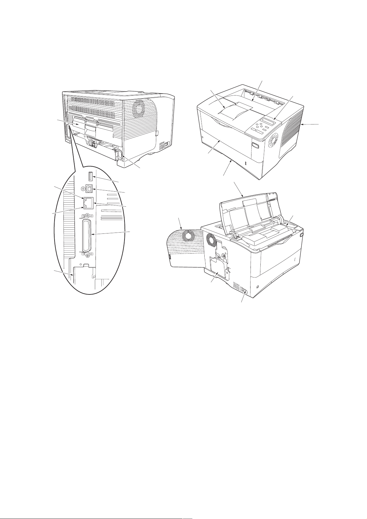
1-1-2 Parts names
(1) Overall
2F7
1. Top cover
2. Paper stopper
3. Top tray
4. Operation panel
5. Toner container
6. Right side cover
7. Paper cassette
8. MP (Multi-Purpose) tray
9. Left side cover
10. Power switch
Figure 1-1-1
11. Waste toner box
12. Rear unit
13. USB memory connector
14. USB interface con nector
15. Network indicators
16. Parallel interface connector
17. Option interface slot (Network/
Serial/Memory card/Hard disk)
18. Network interface connector
19. AC inlet
1-1-3
Page 14
2F7
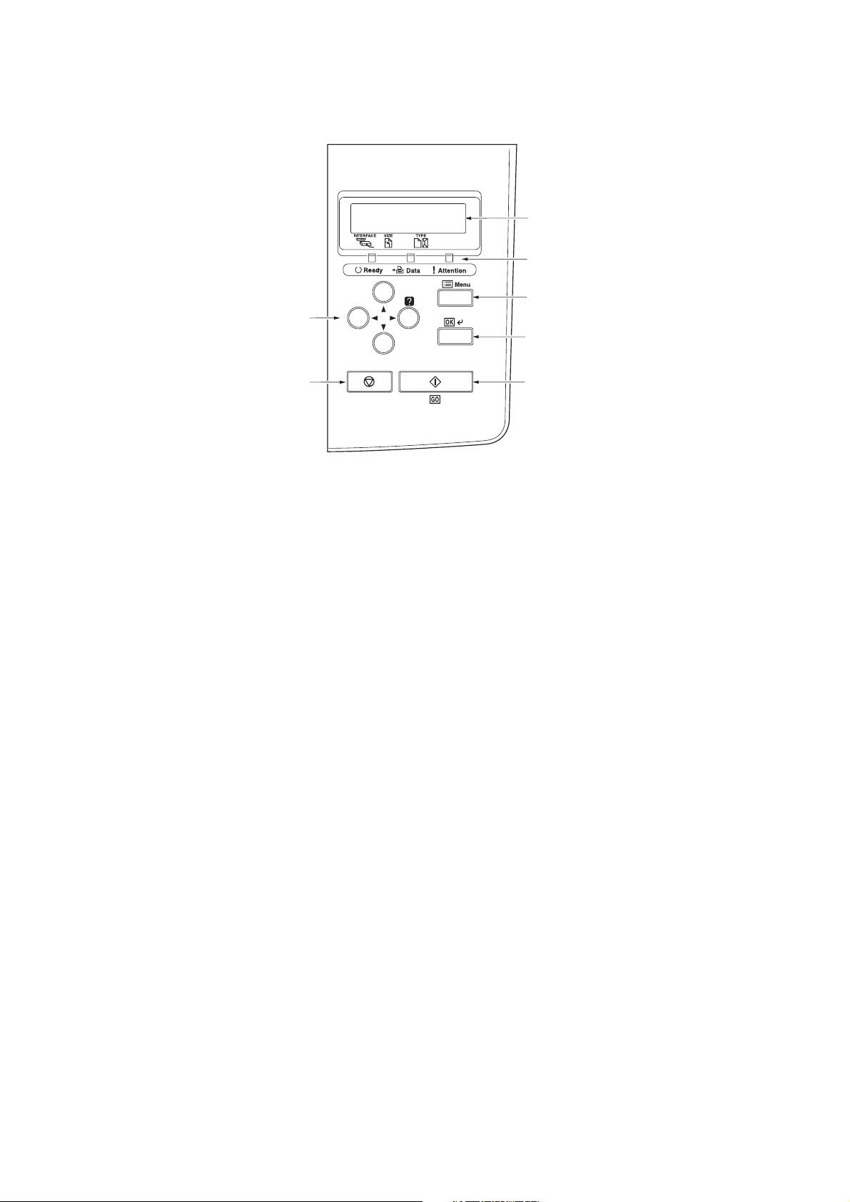
(2) Operation panel
Ready
PAR A4 PLAIN
Figure 1-1-2
1. Message display
2. Indicators
3. Menu key
4. OK key
5. Cursor keys
6. GO key
7. Cancel key
1-1-4
Page 15
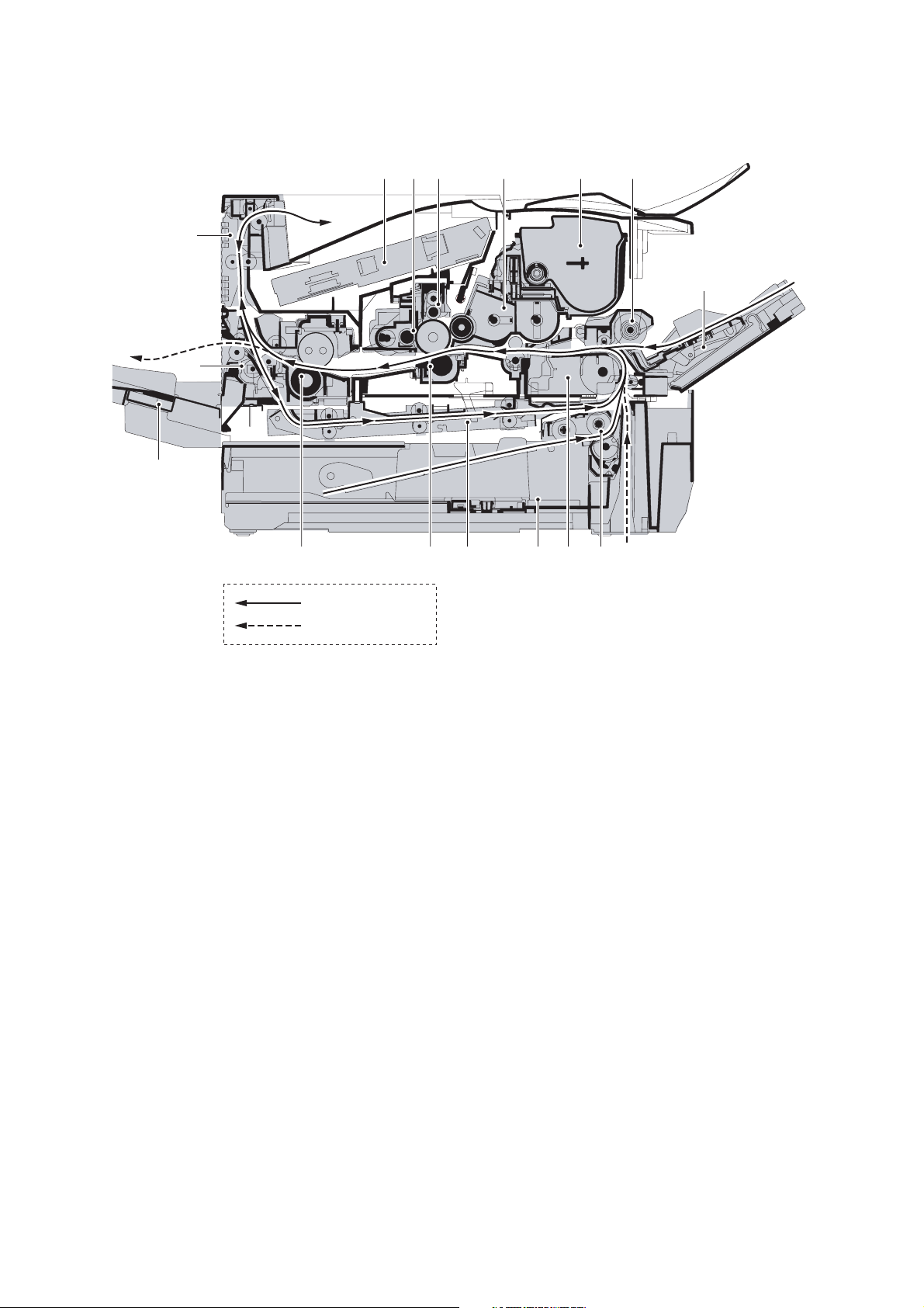
1-1-3 Machine cross section
2F7
Paper path
Paper path (optional)
Figure 1-1-3 Machine cross section
1. MP (Multi-Purpose) tray
2. MP tray paper feed unit
3. Toner container
4. Developer unit
5. Main charger unit
6. Drum unit
7. Laser scanner unit
8. Paper exit section
9. Rear unit
10. Fuser unit
1 1. Transfer/separation section
12. Duplex paper conveying section
13. Paper cassette
14. Paper conveying section
15. Paper cassette paper feed section
16. Face-up tray (optional)
1-1-5
Page 16

2F7
This page is intentionally left blank.
1-1-6
Page 17
1-2 Installation
1-2-1 Installation environment
1. Temperature: 10 - 32.5°C/50 - 90.5°F
2. Humidity: 15 - 80%RH
3. Power supply: 120 V AC, 9.0 A
220 - 240 V AC, 5.0 A (Average)
4. Power source frequency: 50 Hz ±0.3%/60 Hz ±0.3%
5. Installation location
Avoid direct sunlight or bright lighting. Ensure that the photoconductor will not be exposed to direct sunlight or
other strong light when removing paper jams.
Avoid extremes of temperature and humidity, abrupt ambient temperature changes, and hot or cold air directed
onto the machine.
Avoid dust and vibration.
Choose a surface capable of supporting the weight of the machine.
Place the machine on a level surface (maximum allowance inclination: 1
Avoid air-borne substances that may adversely affect the machine or degrade the photoconductor, such as mercury, acidic of alkaline vapors, inorganic gasses, NOx, SOx gases and chlorine-based organic solvents.
Select a room with good ventilation.
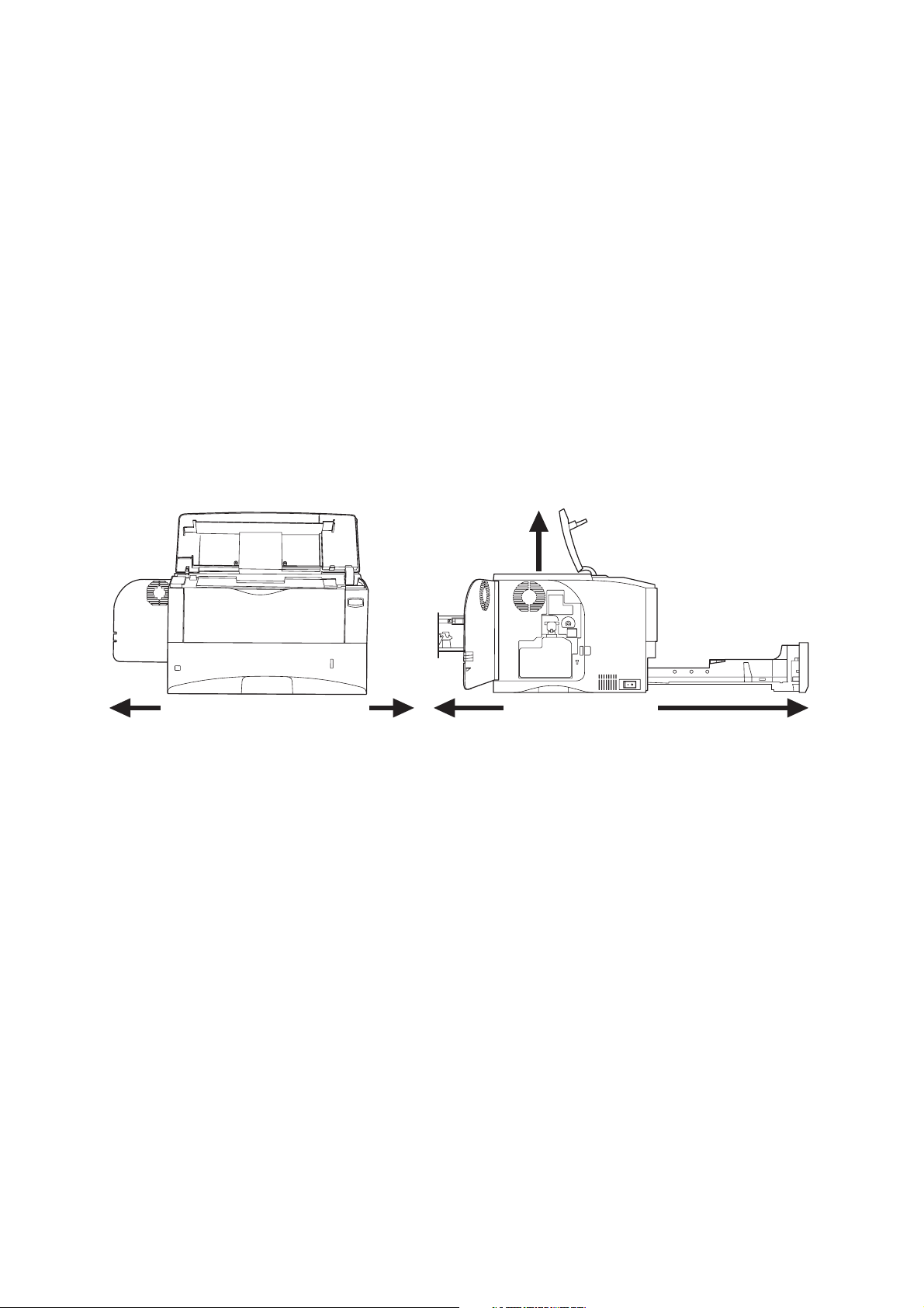
6. Allow sufficient access for proper operation and maintenance of the machine.
Machine front: 60 cm, Machine rear: 20 cm
Machine right: 10 cm, Machine left: 30 cm
Machine top: 75 cm
75 cm
°).
2F7
20 cm 60 cm30 cm 10 cm
Figure 1-2-1
1-2-1
Page 18
2F7
1-2-2 Unpacking and installation
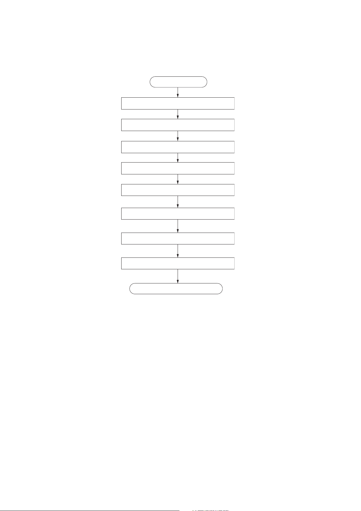
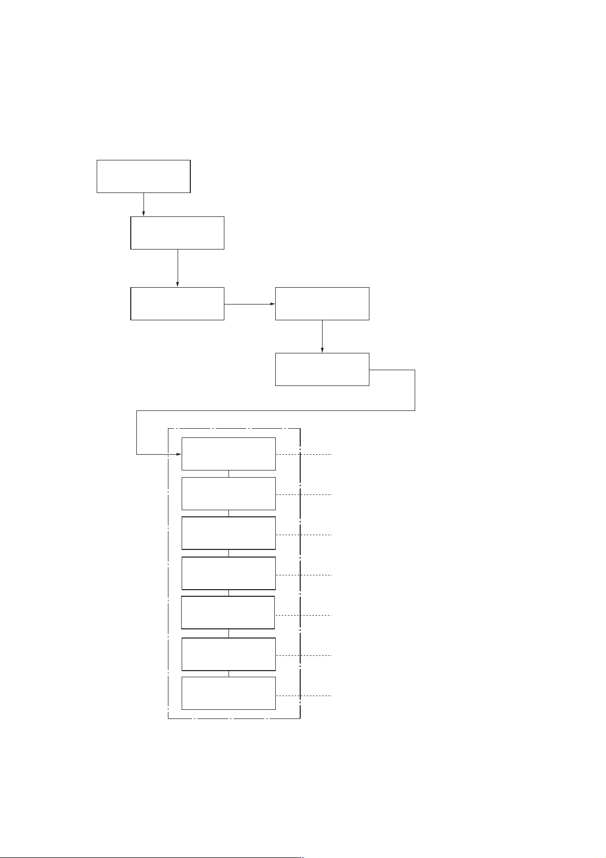
(1) Installation procedure
Installing the toner container and waste toner box.
Start
Unpacking.
Attacihng the label.
Adding paper to paper cassette.
Connecting the printer cables.
Connecting the power cord and toner installing.
Printing a status page for test.
Installing the software.
Completion of the machine installation.
1-2-2
Page 19
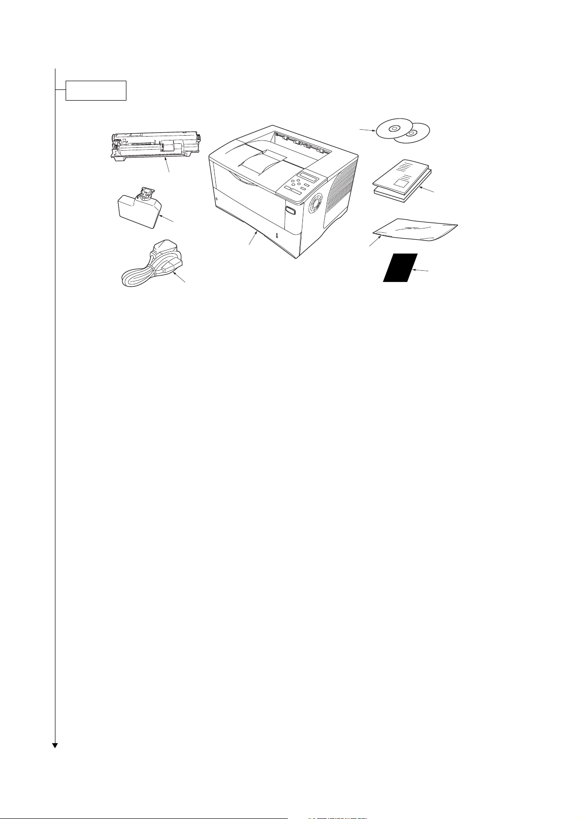
Unpacking.
2F7
Figure 1-2-2 Unpacking
1. Printer
2. Toner container
3. Waste toner box
4. Power cord
5. CD-ROMs
6. Manuals and other printed matter
7. Plastic waste bag
8. Language label sheet
1-2-3
Page 20

2F7
Attaching the label.
1. Attach the included language label sheet on
the indicator as shown in the figure.
Ready
PAR A4 PLAIN
Menu
Language label sheet
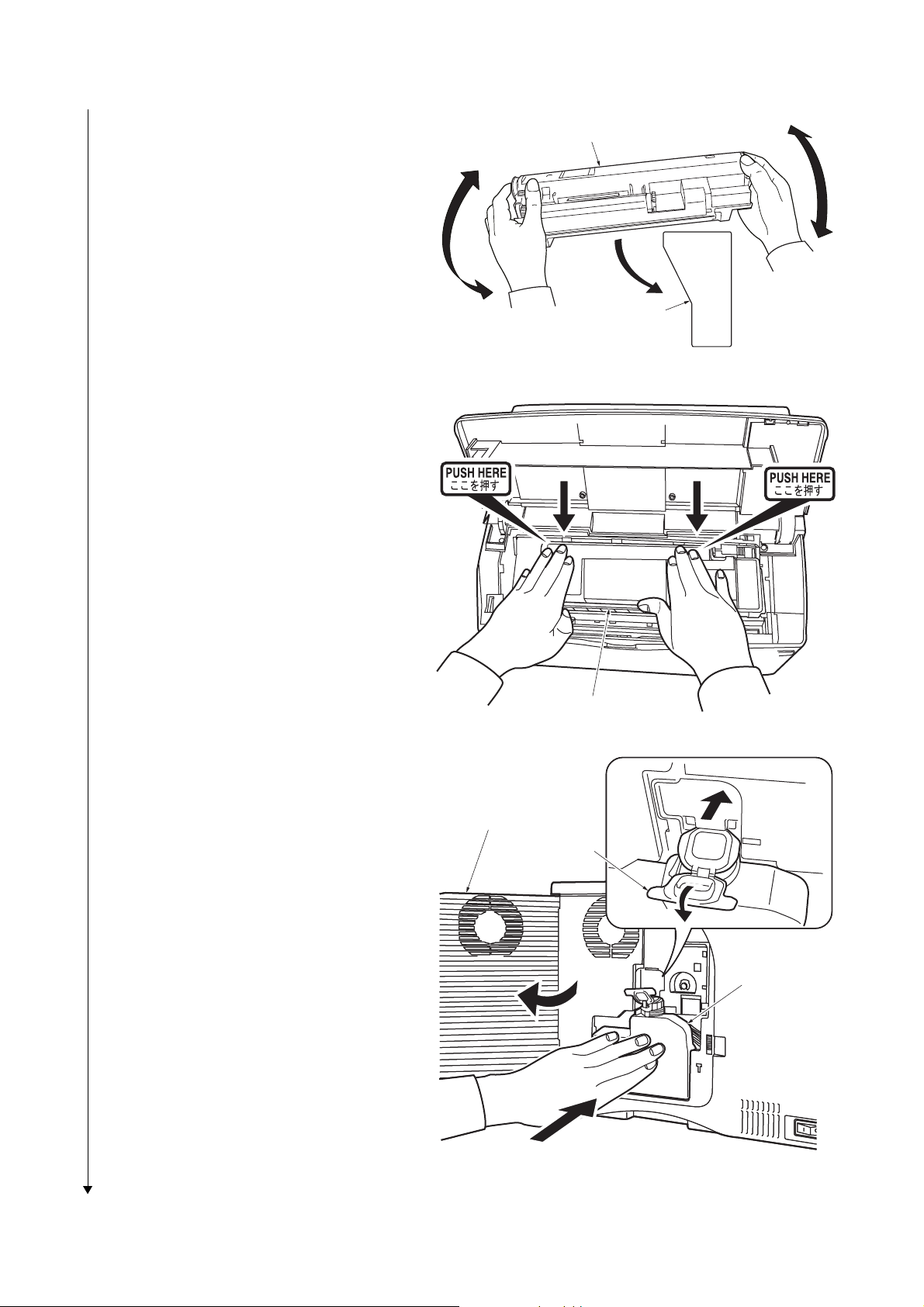
Installing the toner container and waste toner box.
1. Open the top cover.
2. Remove the tape.
Figure 1-2-3
Top cover
1-2-4
Tape
Figure 1-2-4
Page 21
2F7
3. Shake the new toner container at least 10
times as shown in the figure in order to distribute the toner evenly inside the container.
4. Carefully remove the protective seal (orange
colored).
5. Install the toner container into the printer.
6. Push on the PUSH HERE marks on the
toner container until the container clicks into
place.
7. Close the top cover.
Toner container
Protective seal
(orange colored)
Figure 1-2-5
REMOVE THIS TAG
BEFORE ADDING TONER
8. Open the cap of the waste toner box.
9. Open the left side cover.
10.Insert the new waste toner box as shown in
the figure. When the box is set correctly, it
will snap into place.
11.Close the left side cover.
Toner container
Figure 1-2-6
Left side cover
Cap
Waste toner box
Figure 1-2-7
1-2-5
Page 22
2F7
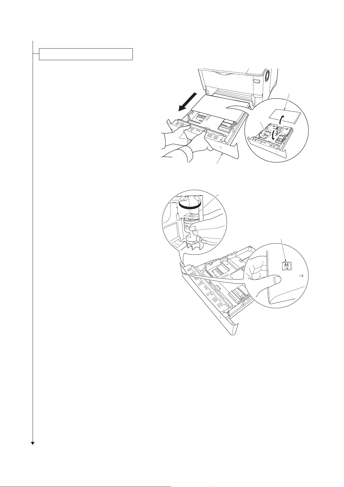
Adding paper to the paper cassette.
1. Pull out the paper cassette and remove the
cassette cover.
2. Push the bottom plate down until it locks.
Cassette cover
Bottom
plate
Paper cassette
Figure 1-2-8
3. Turn the paper size dial so that the size of
the paper you are going to use appears in
the paper size window.
Paper size dial
Paper size window
Figure 1-2-9
1-2-6
Page 23
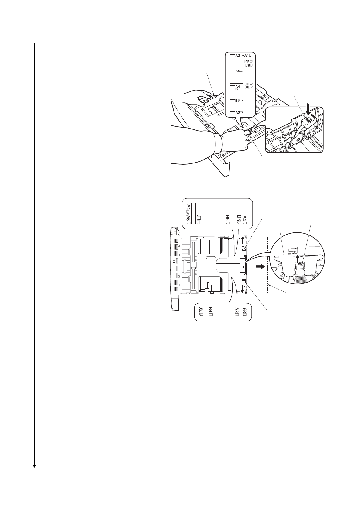
4. Pull the release lever on the right side guide
and slide to the desired paper size.
5. Pull the release lever and slide the paper
stopper to the desired paper size.
If using A3 or Ledger paper, pull out the
extension paper cassettes pushing the lock
lever one by one and adjust them to the
desired paper size.
6. Place the paper in the cassette, with side to
be printed downward, so that the leading
edge is aligned against the paper stopper.
Put the cassette cover.
7. Insert the paper cassette into the slot in the
printer. Push it straight in as far as it will go.
2F7
Side guide
Release lever
Side guide
Figure 1-2-10
Lock lever
Release lever
Paper stopper
Figure 1-2-11
Extension paper
cassette
Lock lever
1-2-7
Page 24
2F7
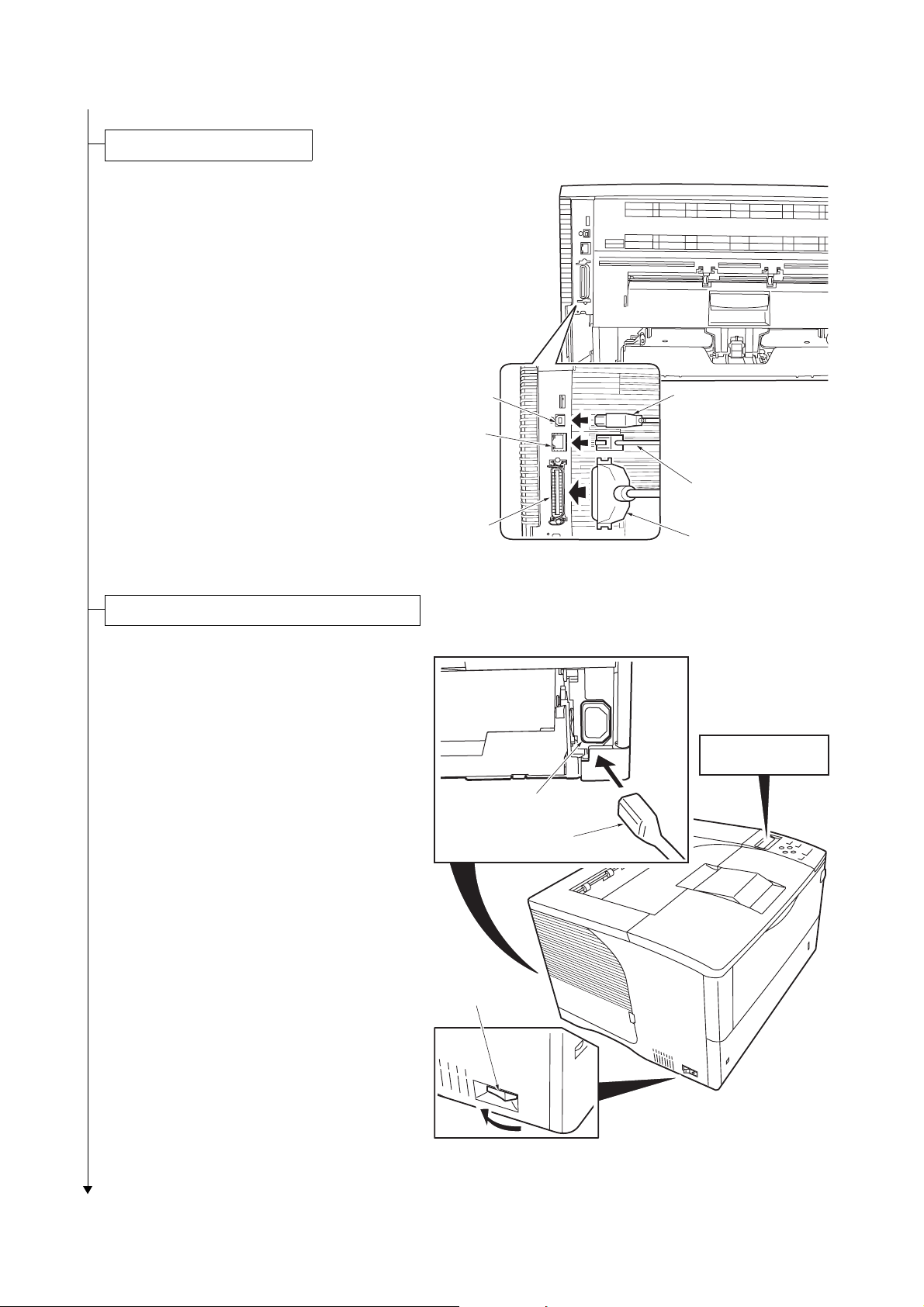
Connecting the printer cables.
s
1. Connect the printer cable (parallel, USB or
network) to the printer and the PC.
USB
Network
Parallel
USB cable
Network cable
Parallel cable
Figure 1-2-12
Connecting the power cord and toner installing.
1. Connect the power cord to the printer’s AC
inlet and the other end into a power outlet.
2. Turn the power switch to on ( | ).
The printer will begin replenishing the toner;
this will take approximately 20 minutes.
3. Wait until the message display indicates [>
MSG language]. The default message language is English.
4. Press T or S key repeatedly until the mes-
sage display shows the desired language
and then press OK key.
If you do not wish to change the setting,
press Cancel key.
5. The display returns to Ready.
> MSG language
? English
AC inlet
Power cord
Power switch
1-2-8
Figure 1-2-13
Page 25

Printing a status page for test.
1. Press the Menu key when [Ready] is dis-
played.
2. Press T or S key to display [Print Status
Page].
3. Press OK key to display [Print Status
Page?].
4. Press OK key. [Processing] will be dis-
played and the status page will be printed.
When printing is complete, [Ready] will
appear again.
5. Check to see if the status page is properly
printed.
Installing the software.
1. Switch on the PC and activate Windows.
If the Welcome to the Found New Hardware
Wizard dialog box displays, select [Cancel].
2. Insert the CD-ROM (Software Library) sup-
plied with the printer into the optical drive of
the PC.The installation program launches
and the License Agreement displays.
If the installation program fails to launch,
use Windows Explorer to access the CDROM and select [Setup.exe].
3. Select [View License Agreement] to read
the information and select [Accept] to proceed.
4. Select [Install KX Driver] and follow the on
screen instructions to complete the software
installation.
When the Select the Printer Port window is
displayed, select a USB port (ex. USB001)
in the list below the Use the following port
radio button.
5. Once the installation is complete, the
[Printer Installed Successfu lly ] d ial og bo x
displays.
When the test page prints correctly, printer
setup is complete. For details on using the
printer, refer to the operation guide.
2F7
Completion of the machine installation.
1-2-9
Page 26
2F7
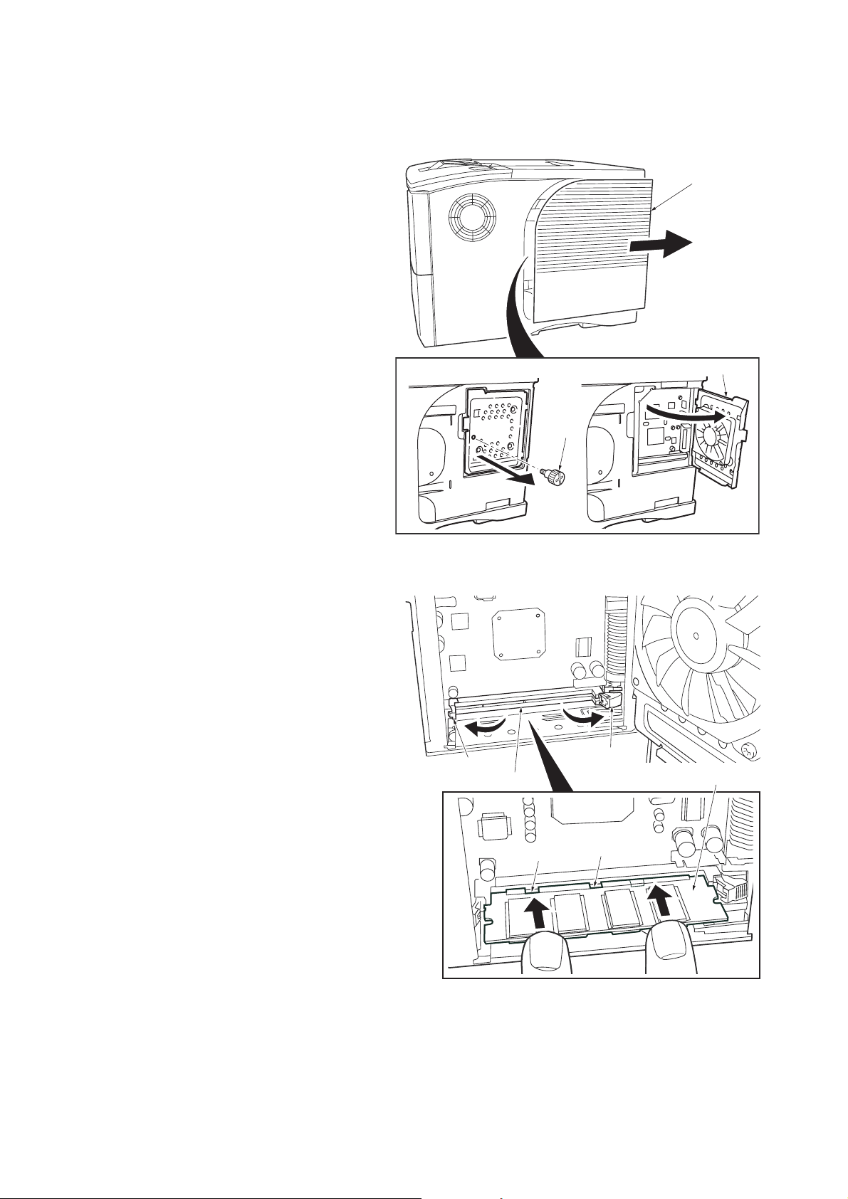
1-2-3 Installing the expanding memory (optional)
<Procedure>
1. Power off the printer and unplug the printer
power cord.
2. Open the right side cover
3. Remove the screw and open the inner
cover.
Right side cover
Inner cover
Screw
4. Push out the clamps on both ends of the
memory socket.
5. Remove the memory from its package.
Aligning the cutouts of the memory with the
matching keys of the socket, carefully plug
the memory into the memory socket until it
clicks in place.
6. Push the two socket clamps to secure the
memory.
7. Close and secure the inner cover by the
screw.
8. Close the right side cover.
Testing the expanded memory
1. To verify that the memory module is working
properly, test it by printing a status page
(refer to operation guide).
Clamp
Memory socket
Figure 1-2-14
Cutout
Clamp
Memory
Cutout
1-2-10
Figure 1-2-15
Page 27
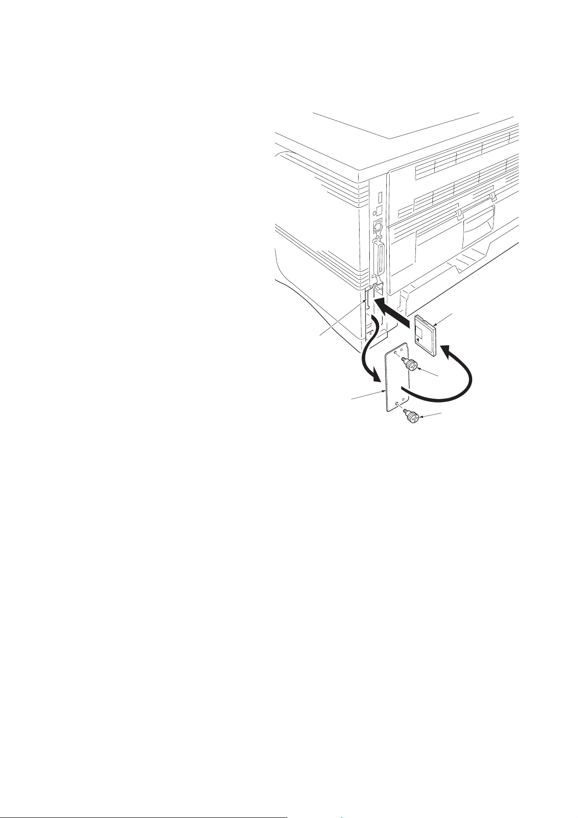
1-2-4 Installing the memory card or hard disk (optional)
<Procedure>
1. Turn off the printer and disconnect the
power cord and printer cable.
2. Remove the two screws and then open the
option interface slot cover.
3. Install the memory card or hard disk into the
memory card slot.
4. Close the option interface slot cover.
2F7
Memory card or
hard disk
Memory card slot
Option interface
slot cover
Screw
Screw
Figure 1-2-16
1-2-11
Page 28
2F7
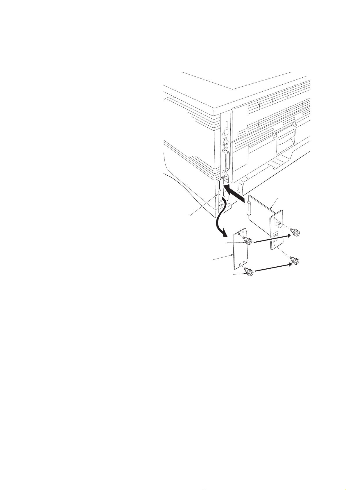
1-2-5 Installing the network interface card (optional)
<Procedure>
1. Turn off the printer and disconnect the
power cord and printer cable.
2. Remove the two screws and then open the
option interface slot cover.
3. Install the network inte rface card.
4. Secure the network interface card by two
screws.
Network interface card
Option interface slot
Option interface
slot cover
Screw
Screw
Figure 1-2-17
1-2-12
Page 29
1-3 Maintenance Mode
1-3-1 Maintenance mode
The printer is equipped with a maintenance function which can be used to maintain and service the machine.
(1) Executing a maintenance item
Message display
Ready
Press the MENU key.
Print
Menu Map
Press the or key several times
until [Others >] is displayed.
2F7
Others >
Service mode items
Press the key.
>>Print
Status Page
>>Print
Event Log
>>Paper Feed
>>Maintenance
>MSG Language
English
Press the or key several
until [>Service >] is displayed.
>Service >
Press the key.
To print a status page for service purpose.
(See page P.1-3-2)
To print an event log (EVENT LOG)
(Displayed when FRPO I1 is set to 1)
(See page P.1-3-8)
To set paper feed operation as printer driver
priority mode.
(See page P.1-3-14)
To reset counter for the maintenance kit.
(See page P.1-3-14)
times
>>Developer
>>DRUM-CTRL
>>Drum
To scroll these items,
press the or key repeatedly.
To initialize the
developer unit. (toner install mode)
(See page P.1-3-15)
To perform a automatic drum refreshing.
(See page P.1-3-15)
To perform a drum refreshing.
(See page P.1-3-16)
1-3-1
Page 30
2F7
/00000000/00000000/00000000/00000000/00000000/00000000/00000000/00000000/00000000/00000000/00000000/
/00000000/00000000/00000000/00000000/00000000/00000000/00000000/00000000/00000000/00000000/00000000/
/00000000/00000000/00000000/00000000/00000000/00000000/00000000/00000000/00000000/00000000/00000000/
/00000000/00000000/00000000/00000000/00000000/00000000/00000000/00000000/00000000/00000000/00000000/
/8088808880808000/8088808880808000/8088808880808000/8088808880808000
/8088808880808000/8088808880808000/8088808880808000/8088808880808000
/8088808880808000/8088808880808000/8088808880808000/8088808880808000
/8088808880808000/8088808880808000/8088808880808000/8088808880808000
/8088808880808000/8088808880808000/8088808880808000/8088808880808000
/8088808880808000/8088808880808000/8088808880808000/8088808880808000
/8088808880808000/8088808880808000/8088808880808000/8088808880808000
/8088808880808000/8088808880808000/8088808880808000/8088808880808000
/00000000/00000000/00000000000000000000000000000000/00000000000000000000000000000000/0000/00/00
DN:SPL9200007 SN:SPL9200010
[XXXXXXXX/XXXXXXXX][XXXXXXX][XXXXXXXX][01/00] Printed Page(s) 9690
/t/P00/S00/U00/F00/N00/D50:DM0301.DAN:0002001001210052
/0020/0020/1061/0811/ 0/ 0/ 0/ 0/ 0/ 0/ 0/ 0/ 0/ 0/ 0/ 0/ 0/ 0/ 0/
/AAAAAAA/AAAAAAA/AAAAAAA/
/AAAAAAA/AAAAAAA/AAAAAAA/
/AAAAAAA/AAAAAAA/
/AAAAAAA/
/AAAAAAA/
/AAAAAAA/
/003D/0005/0005/0005/0000/
/0000/
/RS2/FF/00/[0003-0003]/81/31/50/50/0
00.00.00.00.00.00
Service items Description
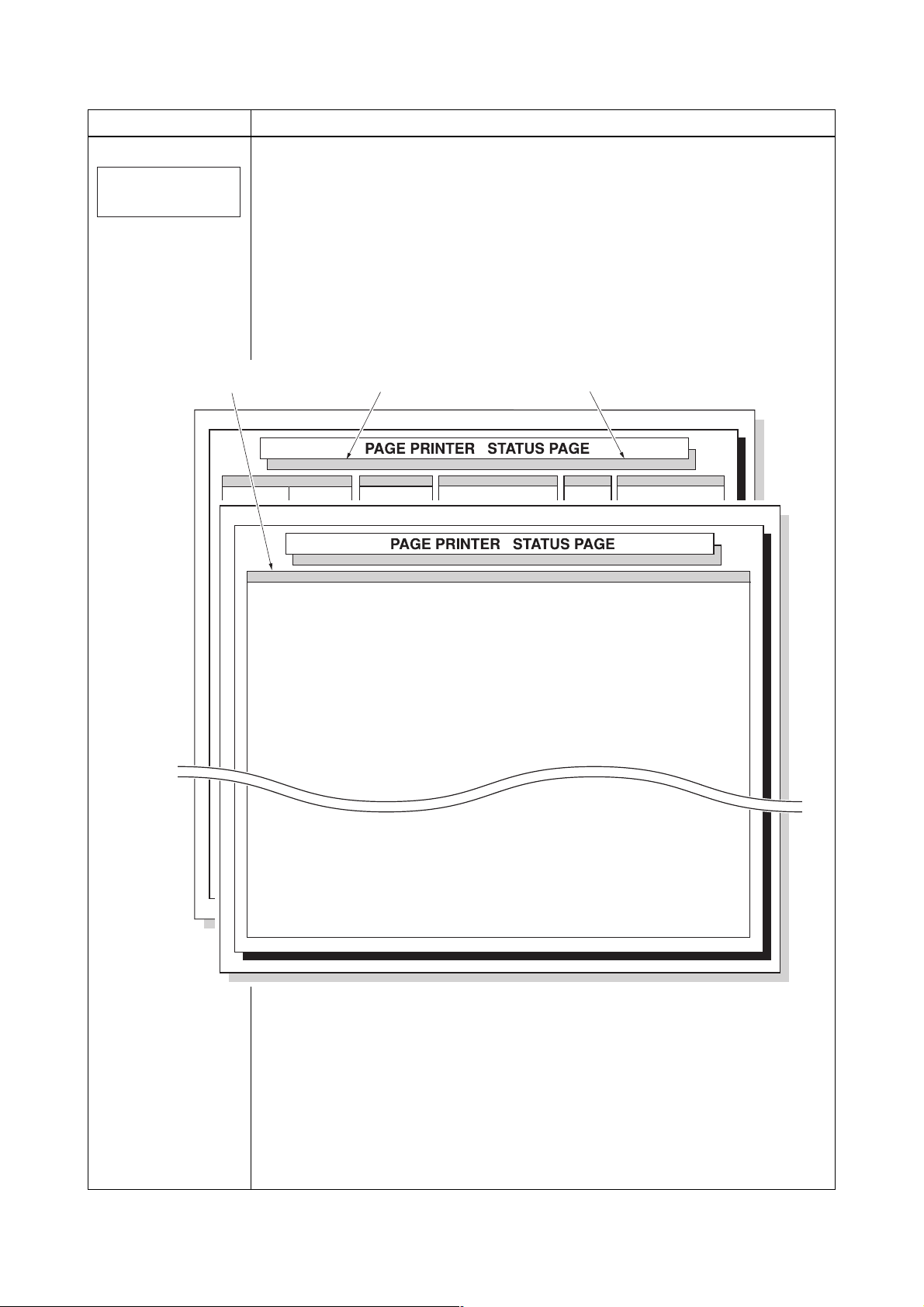
Printing a status page for service purpose
Description
>>Print
Status Page
Prints a status page for service purpose. The status page includes various printing settings
and service cumulative.
Purpose
To acquire the current printing environmental parameters and cumulative information.
Procedure
1. Enter the service mode [>>Print Status Page].
2. Press the OK key. [Print Status Page?] will be displayed.
3. Press the OK key. Five pages will be printed. (The second page includes service
information.
Service information
(Refer to next page) Firmware release date
Firmware version: 132.00
Firmware version: 132.00
Service Information
Main PWB firmware version
Released: 25/Nov/2005
Released: 25/Nov/2005
1-3-2
Figure 1-3-1Service status page
Page 31

Service items Description
Service information
Service information
[XXXXXXXX/XXXXXXXX][XXXXXXX][XXXXXXXX][01/00] Printed pages(s) 9690
/t/P00/S00/U00/F00/N00/D50:DM0301.DAN:0002001001210052
/0020/0020/1061/0811/ 0/ 0/ 0/ 0/ 0/ 0/ 0/ 0/ 0/ 0/ 0/ 0/ 0/ 0/ 0/
/AAAAAAA/AAAAAAA/AAAAAAA/
/AAAAAAA/AAAAAAA/AAAAAAA/
/AAAAAAA/AAAAAAA/
/AAAAAAA/
/AAAAAAA/
/AAAAAAA/
/003D/0005/0005/0005/0000/
/0000/
2F7
/RS2/FF/00/[0003-0003]/81/31/50/50/0
00.00.00.00.00.00
A:1234567890123456
/03030303/03030303/03030303/03000000/00000000/03030303/03030303/
SPD1:0203040508090A0B0C0D0F101112131415161718191A1B1C1D1E1F202122235E
/00/
/00000000000000000000000000000000/00000000000000000000000000000000
/0/0000000000000000000000000000000000000000000000000000000000000000
1-3-3
Page 32

2F7
Service items Description
/00000000/00000000/00000000/00000000/00000000/00000000/00000000/00000000/00000000/00000000/00000000/
/00000000/00000000/00000000/00000000/00000000/00000000/00000000/00000000/00000000/00000000/00000000/
/00000000/00000000/00000000/00000000/00000000/00000000/00000000/00000000/00000000/00000000/00000000/
/00000000/00000000/00000000/00000000/00000000/00000000/00000000/00000000/00000000/00000000/00000000/
/00000000/00000000/00000000/00000000/00000000/00000000/00000000/00000000/00000000/00000000/00000000/
/00000000/00000000/00000000/00000000/00000000/00000000/00000000/00000000/00000000/00000000/00000000/
/00000000/00000000/00000000/00000000/00000000/00000000/00000000/00000000/00000000/00000000/00000000/
/00000000/00000000/00000000/00000000/00000000/00000000/00000000/00000000/00000000/00000000/00000000/
/00000000/00000000/00000000/00000000/00000000/00000000/00000000/00000000/00000000/00000000/00000000/
/00000000/00000000/00000000/00000000/00000000/00000000/00000000/00000000/00000000/00000000/00000000/
/00000000/00000000/00000000/00000000/00000000/00000000/00000000/00000000/00000000/00000000/00000000/
/00000000/00000000/00000000/00000000/00000000/00000000/00000000/00000000/00000000/00000000/00000000/
/00000000/00000000/00000000/00000000/00000000/00000000/00000000/00000000/00000000/00000000/00000000/
/00000000/00000000/00000000/00000000/00000000/00000000/00000000/00000000/00000000/00000000/00000000/
/00000000/00000000/00000000/00000000/00000000/00000000/00000000/00000000/00000000/00000000/00000000/
/00000000/00000000/00000000/00000000/00000000/00000000/00000000/00000000/00000000/00000000/00000000/
/00000000/00000000/00000000/00000000/00000000/00000000/00000000/00000000/00000000/00000000/00000000/
/00000000/00000000/00000000/00000000/00000000/00000000/00000000/00000000/00000000/00000000/00000000/
/00000000/00000000/00000000/00000000/00000000/00000000/00000000/00000000/00000000/00000000/00000000/
/00000000/00000000/00000000/00000000/00000000/00000000/00000000/00000000/00000000/00000000/00000000/
/00000000/00000000/00000000/00000000/00000000/00000000/00000000/00000000/00000000/00000000/00000000/
/00000000/00000000/00000000/00000000/00000000/00000000/00000000/00000000/00000000/00000000/00000000/
/00000000/00000000/00000000/00000000/00000000/00000000/00000000/00000000/00000000/00000000/00000000/
/8088808880808000/8088808880808000/8088808880808000/8088808880808000
/8088808880808000/8088808880808000/8088808880808000/8088808880808000
/8088808880808000/8088808880808000/8088808880808000/8088808880808000
/8088808880808000/8088808880808000/8088808880808000/8088808880808000
/8088808880808000/8088808880808000/8088808880808000/8088808880808000
/8088808880808000/8088808880808000/8088808880808000/8088808880808000
/8088808880808000/8088808880808000/8088808880808000/8088808880808000
/8088808880808000/8088808880808000/8088808880808000/8088808880808000
/00000000/00000000/00000000000000000000000000000000/00000000000000000000000000000000/0000/00/00
DN:SPL9200007 SN:SPL9200010
Detail of service information
No. Items Description
Engine ROM information [Flash ROM version]
Operation panel ROM
information
Boot ROM information [Boot ROM version]
1-3-4
[Operation panel mask ROM version]
Page 33

Service items Description
No. Items Description
Software jumper switch
information
(hexadecimal)
[First byte/second byte (displayed in OEM mode only)]
Total page -
Toner install information -
Parallel I/O information -
Serial information 00: Not connected
USB information 00: Not connected
Operation panel lock sta-
tus (displayed only when
locked)
NVRAM error (displayed
only when any error has
occurred)
First byte
bit 0 = 1: (Fixed)
bit 1 = 0: Overseas, 1: Domestic (Japan)
bit 2, 3 (Not used)
bit 4 = 0: Kyocera, 1: OEM
bit 5 = 0: For Europe, 1: For US
bit 6 = 0: Non MICR mode, 1: MICR mode
bit 7 (Not used)
Second byte: Displayed in OEM mode only
bit0: Framing error
bit1: Overrun error
bit2: Parity error
01: Full-Speed
02: Hi-Speed
Code conversion
01: Partial lock
02: Full lock
ABCDEFGHI J
0123456789
01: ID error
02: Version error
03: Checksum error
04: NVRAM crush error
2F7
NVRAM download 00: Normal
bit0: Font data
bit1: Host data
bit2: Macro data
bit3: Program data
bit4: Operation panel message data download (file name displayed)
bit5: OEM data
bit6: Web template data (version displayed)
bit7: Error occurred
Printable area setting /Top offset/Left offset/Page length/Page width
Left offset for each paper
source
Top offset for each paper
source
Offset for rotation /Top offset/Left offset/
Paper source life counter Total counter large/Total counter small/MP tray
Paper source life counter /Paper feeder 1 total
Paper source life counter /Paper feeder 4 total
/MP tray/Paper cassette1/Paper cassette 2/Paper cassette 3/Paper cassette 4/Paper cassette 5/Duplex
(1/600 inches unit)
/MP tray/Paper cassette 2/Paper cassette 3/Paper cassette 4/
Paper cassette 5/Duplex/
(1/600 inches unit)
(1/600 inches unit)
/Paper feeder 2 total
/Paper feeder 3 total
/Paper feeder 5 total
1-3-5
Page 34

2F7
Service items Description
No. Items Description
Paper source position counter /Duplex
Unit life counter /Drum unit
Maintenance kit life counter -
Unit version /Paper feeder 2/Paper feeder 3/Paper feeder 4/Paper feeder 5/
Unit EEPROM error bit0: Paper feeder 2
bit1: Paper feeder 3
bit2: Paper feeder 4
bit3: Duplex
bit4 to 6: Reserved
bit7: Drum unit
Drum ID -
Serial interface information RS2: RS-232C
RS4: RS-422A
Drum sensitivity information -
Calibration table settings Setting value (FRPO I4), Hexadecimal
Optional paper feeder/stacker
information
1st 2 bytes
bit0: MP tray
bit1 to 6: Paper feeder 1 to 6
bit7: Duplex
bit8: Reserved
bit9: Reserved
2nd 2 bytes
bit0: Face up
bit1: Face down
bit2: Reserved
bit3: Reserved
bit4 to 15: Reserved
bit10 to 15: Reserved
Operation panel message lan-
PMSG command setting (decimal)
guage
Current temperature
0 to 50 °C (in 1 °C increment, “-” = Temperature/humidity sensor
is abnormal.)
Current humidity 25 to 90% RH (in 1% increment)
Absolute humidity
Number of rebooting for verti-
g/m
-
3
cal distortion check
MAC address Fixed asset number (maximum 16 characters)
Media type attributes Media type setting value from 1 to 28 (paper weight)
(unused media type are always 0x00.)
Memory SPD information (slot 1)2 to 6 bytes, 8 to 36 bytes, 94 to 95 bytes (total 32 bytes)
Drum status information -
Drum surface potential infor-
-
mation
Drum sensitivity information -
1-3-6
Page 35

Service items Description
No. Items Description
LSU luminous power distribu-
tion information
DRT correction coefficient
Engine parameter Hexadecimal, 128 bytes (256 digits)
Toner container information -
Drum serial number -
Machine serial number -
NOTE:
Code conversion
ABCDEFGH I J
0123456789
APC PWB table information (1 byte)/actual data (32 bytes)
4 bytes × 11 × 23 groups
2F7
1-3-7
Page 36

2F7
Service items Description
Printing an event log (EVENT LOG)
Description
>>Print
Event Log
Prints the history of paper misfeeds and self-diagnostic errors including up to 16 items from
the latest occurrence of such an error. (If the number of errors exceeds 16, errors will be
deleted sequentially from the oldest one.)
Purpose
To allow machine malfunction analysis based on the frequency of paper misfeeds and selfdiagnostic errors.
Procedure
1. Enter the service mode [>>Print Event log].
2. Press the OK key. [>>Print Event Log?] will be displayed.
3. Press the OK key. A sheet of event log will be printed.
[EB20MA001/2F7_1000.001.0200][E1][B33.01FLB][03]
(1)
Total page 12345 DN:SPL0000000
Firmware version: 2F7_3000.001.35
(4)(2)(3)(5)(6)
(7)(8)
(9)
# Count. Event # Count. Service Code
16 11111 10.48.01.88.01.01
15 10000 10.48.01.88.01.01
14 9999 10.48.01.88.01.01
13 9998 10.48.01.88.01.01
12 9997 10.48.01.88.01.01
11 9996 10.48.01.88.01.01
10 9995 10.48.01.88.01.01
9 9994 10.48.01.88.01.01
8 9993 10.48.01.88.01.01
7 9992 10.48.01.88.01.01
6 9991 10.48.01.88.01.01
5 9990 10.48.01.88.01.01
4 9989 10.48.01.88.01.01
3 9979 10.48.01.88.01.01
2 9969 10.48.01.88.01.01
1 1 10.48.01.88.01.01
10.48.01.88.01.01
(a) (b) (c) (d) (e) (f)
(10)
8 11234 01.6000
7 10000 01.6000
6 9999 01.6000
5 9998 01.6000
4 9997 01.6000
3 9996 01.6000
2 9995 01.6000
1 9994 01.6000
(11)
# Count. item
8 11234 02.00
7 10000 02.00
6 9999 02.00
5 9998 02.00
4 9997 02.00
3 9996 02.00
2 9995 02.00
1 9994 02.00
(12)
J00: 0 J43: 0 C:6000: 4 M00: 1
J05: 0 J44: 0 C:6050: 1
J09: 0 J46:
J10: 0 J47:
J11: 0 J50:
J12: 0 J51:
J13: 0 J52:
J14: 0 J53:
J15: 0 J60:
J16: 0 J61:
(g)
J17: 0 J80:
J18: 0 J81:
J19: 0 J82:
J20: 0 J83:
J21: 0 J84:
J22: 0 J85:
J23: 0 J86:
J30: 0 J87:
J35: 0 J88:
J40: 0 J89:
J41: 0
J42: 0
SN:SPL0000000
(13)
(h)
(i)
Released: 10/Nov/2005
1-3-8
Figure 1-3-2
Page 37

Service items Description
Detail of event log (EVENT LOG) information
No. Items Description
(1) Engine PWB mask version [Engine mask version/Engine software version]
(2) Operation panel PWB mask ver-
sion
(3) BROM version (4) Software jumper switch informa-
tion
(hexadecimal)
[First byte/second byte (dis-
played in OEM mode only)]
(5) Main PWB mask version (6) Main PWB firmware release
date
(7) Total page counter (8) Drum serial number -
-
First byte
bit 0 = 1: (Fixed)
bit 1 = 0: Overseas, 1: Domestic (Japan)
bit 2, 3 (Not used)
bit 4 = 0: Kyocera, 1: OEM
bit 5 = 0: For Europe, 1: For US
bit 6 = 0: Non MICR mode, 1: MICR mode
bit 7 (Not used)
Second byte: Displayed in OEM mode only
-
2F7
(9) Printer serial number -
(10) Paper Jam Log # Count. Event
Remembers 1 to 16 of
occurrence. If the occurrence of the previous
paper jam is less than
16, all of the paper jams
are logged. When the
occurrence execeeds
16, the oldest occurrence is removed.
The total page count
at the time of the
paper jam.
Log code (2 digit,
hexadecimal, 6
categories)
(a) Cause of a
paper jam
(b) Posistion of
paper jam
(c) Paper source
(d) Paper size
(e) Paper type
(f) Paper exit
Refer to the next
page for the details
of each log code.
1-3-9
Page 38

2F7
Service items Description
No. Items Description
(10)
cont.
(a) Cause of paper jam
10: Paper does not arrive at the registration sensor. (MP tray) [42]
10: Paper does not arrive at the registration sensor. (Cassette 1) [31]
10: Paper does not arrive at the registration sensor. (Cassette 2) [31]
10: Paper does not arrive at the registration sensor. (Cassette 3) [31]
10: Paper does not arrive at the registration sensor. (Cassette 4) [31]
10: Paper does not arrive at the registration sensor. (Cassette 5) [31]
10: Paper does not arrive at the registration sensor. (Duplex conveying) [31]
11: Paper does not pass the registration sensor. [48]
12: Paper remains at the registration sensor when power is turned on. [48]
20: Paper does not arrive at the exit sensor. [48]
21: Paper does not pass the exit sensor. [47]
22: Paper remains at the exit sensor when powe r is turned on. [47]
30: Paper does not arrive at the paper feeder 1 paper feed sensor. (Cassette 2) [32]
30: Paper does not arrive at the paper feeder 1 paper feed sensor. (Cassette 3) [33]
30: Paper does not arrive at the paper feeder 1 paper feed sensor. (Cassette 4) [33]
30: Paper does not arrive at the paper feeder 1 paper feed sensor. (Cassette 5) [33]
31: Paper does not pass the paper feeder 1 paper sensor. [32]
32: Paper remains at the paper feeder 1 paper feed sensor when power is turned on. [32]
40: Paper does not arrive at the paper feeder 2 paper feed sensor. (Cassette 3) [33]
40: Paper does not arrive at the paper feeder 2 paper feed sensor. (Cassette 4) [34]
40: Paper does not arrive at the paper feeder 2 paper feed sensor. (Cassette 5) [34]
41: Paper does not pass the paper feeder 2 paper sensor. [33]
42: Paper remains at the paper feeder 2 paper feed sensor when power is turned on. [33]
50: Paper does not arrive at the paper feeder 3 paper feed sensor. (Cassette 4) [34]
50: Paper does not arrive at the paper feeder 3 paper feed sensor. (Cassette 5) [35]
51: Paper does not pass the paper feeder 3 paper sensor. [34]
52: Paper remains at the paper feeder 3 paper feed sensor when power is turned on. [34]
60: Paper does not arrive at the paper feeder 4 paper feed sensor. (Cassette 5) [35]
61: Paper does not pass the paper feeder 4 paper sensor. [35]
62: Paper remains at the paper feeder 4 paper feed sensor when power is turned on. [35]
A1: Paper does not arrive at the duplex sensor. (Rear unit) [47]
A2: Paper does not pass the duplex sensor. (Rear unit) [47]
A3: Paper does not arrive at the duplex jam sensor. (Rear unit) [49]
A4: Paper does not pass the duplex jam sensor. (Rear unit) [49]
A5: Paper remains at the duplex jam sensor when power is turned on. [49]
E0: Paper misfeed occurs due to forced stop when an error occurs during printing. (such as
opening of a cover) [00]
E1: The length of paper is shorter than designated for the paper cassette. [47]
E2: A5 lengthwise paper has been fed despite the paper cassette is set to A4 widthwise (see
reference 1 below). [00]
E3: Paper cassette 1 was opened in the middle of duplex printing (see reference 2 below). [49]
F0: Paper does not arrive at the face down tray paper full sensor. [47]
F1 to FE: Paper misfeed by another cause. [00]
1-3-10
Note:
Values (hexadecimal) within [ ] indicate paper misfeed locations.
Reference 1:
Widthwise A4 size and lengthwise A5 are identical in length, however, the fuser temperature
differs. Detecting the fuser temperature depending on this temperature difference allows
detection of paper misfeed due to a wrong paper size.
Reference 2:
The DU cover of the duplex paper conveying section is designed to operate as being held
against the main unit as the paper cassette is installed. (Paper feeding fails when the paper
cassette is not properly installed because of the resultant space between the DU cover and the
main unit.) Therefore, paper jam occurs if the paper cassette is opened in the middle of duplex
printing.
Page 39

Service items Description
(Fuser)
(Inside the printer)
(Rear unit)
(Duplex conveying)
(Face down tray)
No. Items Description
(10)
(b) Detail of jam location
cont.
Printer
3
(Face down tray)
(Face down tray)
(Inside the printer)
(Inside the printer)
48
49
(Duplex conveying)
(Duplex conveying)
5
(Cassette 1)
(Cassette 2)
(Cassette 3)
(Cassette 4)
(Cassette 5)
(Rear unit)
(Rear unit)
Face
up tray
Paper
feeder 1
Paper
feeder 2
Paper
feeder 3
Paper
feeder 4
47
(Fuser)
(Fuser)
2
4
2F7
(MP tray)
42
1
31
6
32
7
33
8
34
9
35
Sensors
1
Registration sensor
2
Paper exit sensor
3
Face down tray
paper full sensor
4
Duplex sensor
5
Duplex jam sensor
6 7 8 9
Paper feed sensor
(Paper feeder)
Figure 1-3-3
1-3-11
Page 40

2F7
Service items Description
No. Items Description
(10)
cont.
(c) Detail of paper source (Hexadecimal)
00: MP tray
01: Paper cassette 1 (printer)
02: Paper cassette 2 (paper feeder 1)
03: Paper cassette 3 (paper feeder 2)
04: Paper cassette 4 (paper feeder 3)
05: Paper cassette 5 (paper feeder 4)
06 to 09: Reserved
(d) Detail of paper size (Hexadecimal)
01: Monarch
02: Business
03: International DL
04: International C5
05: Executive
06: Letter-R
86: Letter-E
07: Legal
08: A4R
88: A4E
09: B5R
89: B5E
0A: A3
0B: B4
(e) Detail of paper type (Hexadecimal)
01: Plain
02: Transparency
03: Preprint
04: Labels
05: Bond
06: Recycle
07: Vellu m
08: Rough
09: Letter head
(f) Detail of paper exit location (Hexadecimal)
0C: Ledger
0D: A5R
8D: A5E
0E: A6
0F: B6
10: Commercial #9
11: Commercial #6
12: ISO B5
13: Custom size
1E: C4
1F: Postcard
20: Reply-paid postcard
21: Oficio II
22: Special 1
0A: Color
0B: Prepunched
0C: Envelope
0D: Cardstock
0E: Coated
0F: 2nd side
10: Media 16
11: High quality
23: Special 2
24: A3 wide
25: Ledger wide
26: Full bleed paper
(12 ¥ 8)
27: 8K
28: 16K-R
A8: 16K-E
32: Statement-R
B2: Statement-E
33: Folio
34: Western type 2
35: Western type 4
15: Custom 1
16: Custom 2
17: Custom 3
18: Custom 4
19: Custom 5
1A: Custom 6
1B: Custom 7
1C: Custom 8
1-3-12
01: Face down tray
02: Face up tray
03: Reserved
04: Reserved
05: Reserved
0B: Reserved
0C: Reserved
0D: Reserved
0E: Reserved
15: Reserved
16: Reserved
1F: Reserved
20: Reserved
29: Reserved
2A: Reserved
33: Reserved
34: Reserved
3D: Reserved
3E: Reserved
47: Reserved
48: Reserved
Page 41

Service items Description
No. Items Description
(1 1) Service Call (Self diagnostic
error) Log
# Count. Self diagnostic error
2F7
code
Remembers 1 to 8 of
occurrence of self diagnostics error. If the occurrence of the previous
diagnostics error is less
than 8, all of the diagnostics errors are logged.
(12) Maintenance Log # Count. Item
Remembers 1 to 8 of
occurrence of replacement. If the occurrence of
the previous replacement
of toner container is less
than 8, all of the occurrences of replacement are
logged.
(13) Counter Log
Comprised of three log
counters including paper
jams, self diagnostics errors,
and replacement of the toner
container.
(g) Jam (h) Self diagnostic error (i) Maintenance
Indicates the log counter
of paper jams depending
on location.
Refer to Paper Jam Log.
All instances including
those are not occurred
are displayed.
The total page count at
the time of the self diagnostics error.
The total page count at
the time of the replacement of the toner container.
This is virtually logged
as the occurrence of the
Toner Empty condition
since the replacement of
the toner container is not
precisely detectable.
Indicates the log counter
of self diagnostics errors
depending on cause.
(See page P.1-4-2)
Example:
C6000: 4
Self diagnostics error
6000 has happened four
times.
(See page P.1-4-2)
Code of maintenance replacing
item (1 byte, 2 category)
01: Toner container
item replacing
Indicates the log
counter depending
on the maintenance item for
maintenance.
T: Toner container
00: Black
M: Maintenance kit
00: MK-430
Example:
T00: 1
The (black) toner
container has been
replaced once.
1-3-13
Page 42

2F7
Service items Description
Setting the paper feed operation (printer drive r priority mode)
>>Paper Feed
Description
With printer driver priority mode, when selecting the specific paper feed location (a paper
cassette or MP tray) with the printer driver (it is not automatic selection), paper is fed from
the selected location. Message "Add Paper" is displayed when there is no paper in that location. When selecting the MP tray as the paper feed location, paper is fed with the timing of
maximum size (Ledger). As for the setting media type (setting the paper type), setting of the
printer driver is notified to the engine PWB. Duplex printing operation is still the ordinary
operation, and paper jam occurs if paper size is different from the setting of the printer.
Purpose
To set the printer driver priority mode which priority is given to the setup of a printer driver
when the ordinary paper feed operation mode is not suitable for the usage condition of the
user.
Method
1. Enter the service mode [>>Paper feed].
2. Press the OK key. Message [Paper feed?] will be displayed.
3. Select the mode (Special? or Normal?) pressing the T key or S key.
Special Ordinary paper feed operation mode (Default)
Normal Printer driver priority mode
>>Maintenance
4. Press the OK key .
Completion
Counter reset for the maintenance kit
Description
The "Install MK" message means that maintenance kit should be replaced at 300,000
images of printing. The interval counter must be manually reset using this service item.
Maintenance kit MK-430 includes the following units:
Drum unit
Developer unit
Fuser unit
Transfer roller
Paper feed system rollers
Purpose
To reset the life counter for the developer unit and drum unit included in maintenance kit.
Procedure for replacing the maintenance kit
Drum unit (See page P.1-5-10)
Developer unit (See page P.1-5-9)
Fuser unit (See page P.1-5-14)
Transfer roller (See page P.1-5-12)
Paper feed system rollers:
Paper feed assembly [paper feed roller and pickup roller] (See page P.1-5-4)
Retard roller (See page P.1-5-5)
MP tray paper feed roller (See page P.1-5-8)
Procedure
1. Enter the service mode [>>Maintenance].
2. Press the OK key. [>>Maintenance?] will be displayed.
3. Press the OK key twice. The counter for each component is reset immediately.
Completion
Note:
Occurrences of resetting the maintenance kits are recorded on the service status page in
number of pages or images at which the maintenance kit was replaced (See page P.1-3-2).
This may be used to determine the possibility that the counter was errorneously or unintentionally reset.
1-3-14
Page 43

Service items Description
Initializing the developer unit (toner install mode)
>>Developer
>>DRUM-CTRL
Description
The new developer unit is shipped from the factory with no toner contained. The developer
can be automatically replete with toner when a toner container is installed onto it and the
printer is turned on. However, because the toner reservoir in the developer has a large
capacity , it requires a lengthy period of time until a substantial amount of toner has been fed
to get the printer ready. (A new developer needs approximately 260 g for triggering the sensor inside.)
Purpose
To execute when the developer unit has been replaced.
Method
1. Enter the service mode [>>Developer] .
2. Press the OK key. [>>Developer?] will be displayed.
3. Press the OK key. [Ready] will be displayed.
4. Turn off and on the printer . [Self test] [Please wait (Adding toner)] will displayed. The
printer continually engages in this mode for a pe riod of approximately 10 minutes,
after which the printer reverts to the [Ready] state. [Ready] will displayed. Developer initialization is finished.
Completion
Automatic drum surface refreshing
Description
The drum surface refreshing operation is normally performed when the power is turned on to
the printer or during warm-up when the printer is recovering from the Sleep mode, but even
then only at those times that the temperature/humidity sensor detects the drum surface to be
in a state of dew condensation. By using this mode, it is possible to force the drum surface
refreshing operation to be performed automatically at a predetermined period of time,
regardless of the status detected by the temperature/humidity sensor.
Purpose
To prevent bleeding of the output image when the printer's operating environment is one of
high humidity.
Method
1. Enter the service mode [>>DRUM-CTR L ].
2. Press the OK key. [>>DRUM-CTRL?] will be displayed.
3. Press the OK key .
4. Press the T key or S key and select the desire mode (from 00 to 02)
2F7
00 Mode turned OFF (default)
01 Refreshing operation time (short)
02 Refreshing operation time (long)
5. Press the OK key. The new value is set.
Completion
1-3-15
Page 44

2F7
Service items Description
Drum surface refreshing
>>Drum
Description
Rotates the drum approximately 3 minutes with toner lightly on the overall drum using the
high-voltage output control of the engine PWB. The cleaning blade in the drum unit scrapes
toner off the drum surface to clean it.
Purpose
To clean the drum surface when image failure occurs due to the drum. This mode is effective
when dew condensation on the drum occurs.
Method
1. Enter the service mode [>>Drum].
2. Press the OK key. [>>Drum?] will be displayed.
3. Press the OK key. Drum surface refreshing will start and finish after approximately 3
minutes, after which the printer reverts to the [Ready] state. [Ready] will displayed. Drum
surface refreshing is finished.
Completion
1-3-16
Page 45

2F7
Paper
exit sensor
Paper
feed
sensor
Paper
feed
sensor
Paper
feed
sensor
Paper
feed
sensor
Duplex
sensor
Duplex jam
sensor
Registration
sensor
1-4 Troubleshooting
1-4-1 Paper misfeed detection
(1) Paper misfeed indication
When a paper misfeed occurs, the printer immediately stops printing and displays the paper misfeed message on the
operation panel. To remove paper misfed in the printer, pull out the paper cassette, pull out the rear unit, remove the developer unit or open the duplex cover.
(2) Paper misfeed detection
Paper Jam
MP tray
Paper misfeed location
Figure 1-4-1
Face down tray
paper full sensor
Paper
Paper
exit sensor
exit sensor
Duplex
Duplex
sensor
sensor
Paper misfeed message
Duplex jam
Duplex jam
sensor
sensor
Registration
Registration
sensor
sensor
Paper
Paper
feed
feed
sensor
sensor
Figure 1-4-2
Paper
Paper
feed
feed
sensor
sensor
Paper
Paper
feed
feed
sensor
sensor
Paper
Paper
feed
feed
sensor
sensor
1-4-1
Page 46

2F7
1-4-2 Self-diagnostic function
(1) Self-diagnostic function
This printer is equipped with self-diagnostic function. When a problem is detected, the printer stops printing and display an
error message on the operation panel. An error message consists of a message prompting a contact to service personnel,
total print count, and a four-digit error code indicating the type of the error. (The display varies depending on the type of
the error.)
Call service
6000:012345
Error code Total print
(2) Self diagnostic codes
Code Contents
0150 Engine PWB EEPROM error
Detecting engine PWB EEPROM communication error.
0420 Paper feeder communication error
Communication error between engine
PWB and optional paper feeder.
Call service
F000
Error code
Causes Check procedures/corrective measures
Improper installation engine PWB
EEPROM.
Defective engine
PWB
Improper installation paper feeder.
Defective harness
between connect-L
PWB (YC2) and
paper feeder interface connector, or
improper connector insertion.
Defective harness
between connect-L
PWB (YC6) and
engine PWB
(YC4), or improper
connector insertion.
Defective engine
PWB.
Defective paper
feeder.
Error power off
F030
Error code
Remarks
Check engine PWB EEPROM installation,
Remedy.
Replace the engine PWB (See page P.1-5-
21).
Follow installation instruction carefully again.
Reinsert the connector. Also check for continuity within the connector harness. If none,
remedy or replace the harness.
Reinsert the connector. Also check for continuity within the connector harness. If none,
remedy or replace the harness.
Replace the engine PWB (See page P.1-5-
21).
Replace the paper feeder.
1-4-2
Page 47

2F7
Code Contents
2000 Main motor error
MMOTRDYN signal does not go low
within 2 s after MMOTONN signal goes
low.
2200 Drum motor error
DMOTRDYN signal does not go low
within 2 s after DMOTONN signal goes
low.
Remarks
Causes Check procedures/corrective measures
Defective harness
between main
motor and engine
PWB (YC10), or
improper connector insertion.
Defective main
motor drive transmission system.
Defective main
motor.
Defective engine
PWB.
Defective harness
between drum
motor and engine
PWB (YC11), or
improper connector insertion.
Defective drum
motor drive
transmission
system.
Defective drum
motor.
Defective engine
PWB.
Reinsert the connector. Also check for continuity within the connector harness. If none,
remedy or replace the harness.
Check if the rollers and gears rotate
smoothly. If not, grease the bushings and
gears. Check for broken gears and replace if
any.
Replace the main motor.
Replace the engine PWB (See page P.1-5-
21).
Reinsert the connector. Also check for conti-
nuity within the connector harness. If none,
remedy or replace the harness.
Check if the gears rotate smoothly. If not,
grease the bushings and gears. Check for
broken gears and replace if any.
Replace the drum motor.
Replace the engine PWB (See page P.1-5-
21).
4000 Polygon motor (laser scanner unit)
error
POLRDYN signal does not go low within
2 s after POLONN signal goes low.
Defective harness
between polygon
motor and main
PWB (YC10), or
improper connector insertion.
Defective harness
between main
PWB (YC11) and
engine PWB
(YC12), or
improper connector insertion.
Defective laser
scanner unit.
Defective engine
PWB.
Defective main
PWB.
Reinsert the connector. Also check for continuity within the connector harness. If none,
remedy or replace the harness.
Reinsert the connector. Also check for continuity within the connector harness. If none,
remedy or replace the harness.
Replace the laser scanner unit (See page
P.1-5-31).
Replace the engine PWB (See page P.1-5-
21).
Replace the main PWB (See page P.1-5-
25).
1-4-3
Page 48

2F7
Code Contents
4200 Laser output (pin photo sensor) error
The pin photo signal (PDN) is not output
within a specified time after the polygon
motor ready signal (POLRDYN)
becomes ready (L level).
5100 Short-circuited main charger output
Five pages have been printed with the
main charger output shortcircuited.
6000 Broken fuser heater lamp M wire
The temperature does not rise 1
the fuser heater lamp M has been turned
on continuously 15 s during waming-up
or at standby.
The temperature does not rise 1
the fuser heater lamp S has been turned
on continuously 15 s during waming-up
or at standby.
The temperature does not rise 1
the fuser heater lamp S has been turned
on continuously 5 s.
°C after
°C after
°C after
Remarks
Causes Check procedures/corrective measures
Defective harness
between PD PWB
(YC1) and main
PWB (YC12), or
improper connector insertion.
Defective APC
PWB.
Defective PD
PWB.
Defective main
PWB.
Drum unit installed
incorrectly.
Engine PWB
installed incorrectly.
Defective engine
PWB.
Poor contact in the
fuser thermistor M
connector terminals.
Fuser thermistor M
installed incorrectly.
Thermal cutout
triggered.
Fuser heater lamp
M installed incorrectly.
Reinsert the connector. Also check for continuity within the connector harness. If none,
remedy or replace the harness.
Replace the laser scanner unit (See page
P.1-5-31).
Replace the laser scanner unit (See page
P.1-5-31).
Replace the main PWB (See page P.1-5-
25).
Verify harness is not pinched in the drum
unit.
Verify harness is not pinched in the engine
PWB.
Replace the engine PWB (See page P.1-5-
21).
Reinsert the connector (See page P.1-5-19).
Check and reinstall if necessary (See page
P.1-5-19).
Check for continuity. If none, replace the
thermal cutout (See page P.1-5-19).
Check and reinstall if necessary (See page
P.1-5-19).
6020 Abnormally high fuser thermistor M
temperature
Fuser thermistor M detects abnormally
temperature.
1-4-4
Broken fuser
heater lamp M
wire.
Shorted fuser thermistor M.
Defective engine
PWB.
Check for continuity. If none, replace the
fuser heater lamp M (See page P.1-5-15).
Measure the resistance. If it is 0 Ω, replace
the fuser thermistor M (See page P.1-5-19).
Replace the engine PWB (See page P.1-5-
21).
Page 49

2F7
Code Contents
6030 Broken fuser thermistor M wire
Input (A/D value) from fuser thermistor M
is less than 1 for more than 2 s.
Input (A/D value) from fuser thermistor S
is less than 1 for more than 3 s.
6100 Broken fuser heater lamp S wire
After changing to fuser thermistor S,
input from of fuser thermistor S control
temperature compared to 10
in 5 s.
°C was low
Remarks
Causes Check procedures/corrective measures
Poor contact in the
fuser thermistor M
connector terminals.
Broken fuser thermistor M wire.
Fuser thermistor M
installed incorrectly.
Thermal cutout
triggered.
Fuser heater lamp
M installed incorrectly.
Broken fuser
heater lamp M
wire.
Fuser heater lamp
S installed incorrectly.
Broken fuser
heater lamp S wire.
Reinsert the connector (See page P.1-5-19).
Measure the resistance. If it is ∞ Ω, replace
the fuser thermistor M (See page P.1-5-19).
Check and reinstall if necessary (See page
P.1-5-19).
Check for continuity. If none, replace the
thermal cutout (See page P.1-5-19).
Check and reinstall if necessary (See page
P.1-5-15).
Check for continuity. If none, replace the
fuser heater lamp M (See page P.1-5-15).
Check and reinstall if necessary (See page
P.1-5-15).
Check for continuity. If none, replace the
fuser heater lamp S (See page P.1-5-15).
6120 Abnormally high fuser thermistor S
temperature
Fuser thermistor S detects abnormally
temperature.
6130 Broken fuser heater lamp S wire
Input (A/D value) from fuser thermistor S
is less than 1 for more than 500 ms.
6400 Zero cross signal error
The ZCROSS signal does not reach the
engine PWB for more than 1 s.
Shorted fuser thermistor S.
Defective engine
PWB.
Poor contact in the
fuser thermistor S
connector terminals.
Broken fuser thermistor S wire.
Fuser thermistor S
installed incorrectly.
Defective harness
between connect-L
PWB (YC8) and
engine PWB
(YC3), or improper
connector insertion.
Defective connection between
power source unit
(YC103) and connect-L PWB (YC1).
Defective power
source unit.
Measure the resistance. If it is 0 Ω, replace
the fuser thermistor S (See page P.1-5-19).
Replace the engine PWB (See page P.1-5-
21).
Reinsert the connector (See page P.1-5-19).
Measure the resistance. If it is ∞ Ω, replace
the fuser thermistor S (See page P.1-5-19).
Check and reinstall if necessary (See page
P.1-5-19).
Reinsert the connector. Also check for continuity within the connector harness. If none,
remedy or replace the harness.
Reinsert the connector.
Replace the power source unit (See page
P.1-5-27).
Defective engine
PWB.
Replace the engine PWB (See page P.1-5-
21).
1-4-5
Page 50

2F7
Code Contents
7000 Toner motor lock error
A motor over-current signal is detected
continuously for 5 seconds since the
toner motor is activated.
7410 Drum unit non- installing error
The drum unit is not installed or not
installed properly.
The drum PWB EEPROM does not communicate normally.
Remarks
Causes Check procedures/corrective measures
Lump of toner
inside toner container.
Defective toner
replenishment
drive system.
Defective toner
motor.
Defective engine
PWB.
The drum unit is
not installed.
Defective connection drum PWB
(YC1) and connect-L PWB (YC3).
Defective drum
PWB EEPROM.
Defective engine
PWB.
Replace the toner container.
Replace the developer unit (See page P.1-5-
9).
Replace the developer unit (See page P.1-5-
9).
Replace the engine PWB (See page P.1-5-
21).
Install the drum unit (See page P.1-5-10).
Check the connection of connectors drum
PWB (YC1) and connect-L PWB (YC3).
(See page P.1-4-9, refer to figure 1-4-3)
Replace the drum unit (See page P.1-5-10).
Replace the engine PWB (See page P.1-5-
21).
F000 Communication problem between the
main PWB and operation panel PWB
Communication is failed between the
operation panel PWB and the main
PWB.
F010 Main PWB (system DIMM PWB)
checksum error
Checksum failed with system DIMM
PWB on the main PWB.
F020 Main or expanded memory error
Checksum failed with main memory
(RAM) on the main PWB or expanded
memory (DIMM).
F030 General failure
Miscellaneous failure with the main
PWB, other than F000, F010, and F020,
above.
Defective system
DIMM PWB.
Defective main
PWB.
Defective operation panel PWB.
Defective main
PWB.
Defective system
DIMM PWB.
Defective system
main memory
(RAM) on the main
PWB.
Defective main
PWB.
Defective
expanded memory
(DIMM).
Defective mainPWB.
Replace the system DIMM PWB.
Replace the main PWB (See page P.1-5-
30).
Replace the operation panel PWB.
Replace the main PWB (See page P.1-5-
30).
Replace the system DIMM PWB.
Replace the main PWB (See page P.1-5-
30).
Replace the main PWB (See page P.1-5-
30).
Replace the expanded memory (DIMM)
(See page P.1-2-10).
Turn the power off/on to restart the printer.If
the error is not resolved, replace main PWB
(See page P.1-5-30).
1-4-6
Page 51

2F7
Code Contents
Causes Check procedures/corrective measures
F040 Main PWB - engine PWB communica-
tion error
Communication between main PWB and
engine PWB is failed.
F226 Main PWB video data control error Defective main-
Defective harness
between engine
PWB (YC12) and
main PWB (YC1 1),
or improper connector insertion.
Defective engine
PWB.
PWB.
Remarks
Reinsert the connector. Also check for continuity within the connector harness. If none,
remedy or replace the harness.
Replace the engine PWB (See page P.1-5-
21).
Turn the power off/on to restart the printer.If
the error is not resolved, replace main PWB
(See page P.1-5-30).
1-4-7
Page 52

2F7
1-4-3 Image formation problems
(1)Completely blank
printout.
P.1-4-9 P.1-4-10 P.1-4-11 P.1-4-11 P.1-4-12
(6)Black vertical
streaks.
ABC
123
P.1-4-12 P.1-4-12 P.1-4-13 P.1-4-13 P.1-4-13
(2)All-black printout. (3)Dropouts. (4)Black dots. (5)Black horizontal
ABC
123
(7)Unsharpness. (8)Gray background. (9)Dirt on the top
ABC
123
ABC
123
edge or back of the
paper.
ABC
123
streaks.
ABC
123
(10)Undulated printing at the left edge
(scanning start position).
This vertical
line should
be straight.
1-4-8
Page 53

(1) Completely blank printout.
Print example Causes Check procedures/corrective measures
2F7
No transfer
charging.
No
developing bias
output.
Poor contact of engine
PWB’s transfer bias out-
Check the installation position of the engine PWB.
Refer to figure 1-4-3 below.
put terminal and printer’s
contact (spring).
Printer bottom
Engine PWB
Contact
(spring)
Main charger
output terminal
Developing bias
output terminal
Contact
(spring)
Contact
(spring)
Separation bias
output terminal
Defective engine PWB. Replace the engine PWB (See page P.1-5-21).
Poor contact of engine
PWB’s developing bias
Check the installation position of the engine PWB.
Refer to figure1-4-3 above.
output terminal and
printer’s contact (spring).
Poor contact of engine
PWB’s developing bias
Check the installation of the developer unit.
Refer to figure 1-4-4 below.
output terminal and
develper unit’s contact.
Contact
(spring)
Transfer bias
output terminal
No laser
beam
output.
Developing unit
Developing
bias output
terminal
A
A
Contact
Printer inside
Figure 1-4-3
Defective engine PWB. Replace the engine PWB (See page P.1-5-21).
Defective laser scanner
Replace the laser scanner unit (See page P.1-5-31).
unit.
Defective main PWB. Replace the main PWB (See page P.1-5-25).
1-4-9
Page 54

2F7
(2) All-black printout.
Print example Causes Check procedures/corrective measures
No main
charging.
Defective main charger
unit.
Poor contact of engine
PWB’s main charger output terminal and main
charger unit’s contact
(spring).
Drum PWB
connector (YC1)
Main
charger
unit
Drum unit
Contact (spring)
Replace the main charger unit (See page P.1-5-11).
Check the installation of the drum (main charger) unit.
Refer to figure 1-4-5 below.
Printer left side
B
Contact
(spring)
C
Connect-L PWB
connector (YC3)
A
A
Drum unit
Main charger
output terminal
B
C
Figure 1-4-4
Drum
grounding
terminal
Poor contact of engine
PWB’s main charger out-
Check the installation position of the engine PWB.
(See page P.1-5-21 and P.1-4-9, refer to figure 1-4-3)
put terminal and printer’s
contact (spring).
Defective engine PWB. Replace the engine PWB (See page P.1-5-21).
1-4-10
Page 55

(3) Dropouts.
Print example Causes Check procedures/corrective measures
2F7
ABC
123
Defective developing roller (developer
unit).
Defective drum (drum unit). If the defects occur at regular intervals of 94 mm (See page
Fuser unit (heat roller or press roller). If the defects occur at regular intervals of 82 mm or 93 mm
Defective paper specifications. Paper with rugged surface or dump tends to cause dropouts.
If the defects occur at regular intervals of 39 mm (See page
P.2-4-2), the problem may be the damaged developing roller
(in the developer unit). Replace developer unit.
If a developer unit which is known to work normally is available
for check, replace the current developer unit in the printer with
the normal one. If the symptom disappears, replace the devel-
oper unit with a new one (See page P.1-5-9).
P.2-4-2), the problem may be the damaged drum (in the drum
unit). Replace drum unit.
If a drum unit which is known to work normally is available for
check, replace the current drum unit in the pri nte r with the nor-
mal one. If the symptom disappears, replace the drum unit
with a new one (See page P.1-5-10).
(See page P.2-4-2), the problem may be the damaged heat
roller or press roller (in the fuser unit). Replace fuser unit (heat
roller or press roller).
If a fuser unit which is known to work normally is available for
check, replace the current fuser unit in the printer with the nor-
mal one. If the symptom disappears, replace the fuser unit
(heat roller or press roller) with a new one (See page P.1-5-
14).
Replace paper with the one that satisfies the paper specifica-
tions.
Defective transfer roller installation. The transfer roller must be supported by the bushes at the
both ends. Clean the bush to remove oil and debris. Replace
the transfer roller if necessary (See page P.1-5-12).
Defective engine PWB (transfer bias
output circuit).
(4) Black dots.
Print example Causes Check procedures/corrective measures
Defective drum unit. If the defects occur at regular intervals of 94 mm (See page
ABC
123
Replace the engine PWB (See page P.1-5-21).
P.2-4-2), the problem may be the damaged drum (in the drum
unit). Replace drum unit.
If the defects occur at random intervals, the toner may be leak-
ing from the developer unit or drum unit. Replace developer
unit or drum unit (See page P.1-5-9 or P.1-5 - 10).
1-4-11
Page 56

2F7
(5) Black horizontal streaks.
Print example Causes Check procedures/corrective measures
Defective drum unit's ground. Defective drum unit's ground. The contact (spring) in the drum
ABC
123
Defective drum unit. If a drum unit which is known to work normally is available for
(6) Black vertical streaks.
Print example Causes Check procedures/corrective measures
Flawed main charger roller. Replace the main charger unit (See page P.1-5-11).
ABC
Dirty or flawed drum. Clean the drum or, if it is flawed, replace the drum unit (See
123
Defective drum unit. A streak of toner remaining on drum after printing means that
unit and its counter part, the drum grounding terminal in the
printer, must be in a good contact. (See page P.1-4-9, refer to
figure 1-4-3)
check, replace the current drum unit in the pri nte r with the nor-
mal one. If the symptom disappears, replace the drum unit
with a new one (See page P.1-5-10).
page P.1-5-10).
the cleaning blade (in the drum unit) is not working properly.
Replace the drum unit (See page P.1-5-10).
If a drum unit which is known to work normally is available for
check, replace the current drum unit in the pri nte r with the nor-
mal one. If the symptom disappears, replace the drum unit
with a new one (See page P.1-5-10).
Defective developing roller (developer
unit).
(7) Unsharpness.
Print example Causes Check procedures/corrective measures
Defective paper specifications. Paper with rugged surface or dump tends to cause unsharp
EcoPrint setting. The EcoPrint mode can provides faint, unsharp printing
Defective transfer roller. If the transfer roller is contaminated with toner, clean the trans-
Poor contact of engine PWB’s transfer bias output terminal and printer’s
contact (spring).
If a developer unit which is known to work normally is available
for check, replace the current developer unit in the printer with
the normal one. If the symptom disappears, replace the devel-
oper unit with a new one.
printing. Replace paper with the one that satisfies the paper
specifications.
because it acts to conserve toner for draft printing purpose.
For normal printing, turn the EcoPrint mode off by using the
operation panel. For details refer to the printer's operation
guide.
fer roller using a vacuum cleaner or by continuously printing a
low density page until the symptom has faded away.
Check the installation position of the engine PWB.
(See page P.1-5-21 and P.1-4-9 , refer to figure 1-4-3)
1-4-12
Page 57

(8) Gray background.
Print example Causes Check procedures/corrective measures
Print density setting. The print density may be set too high. Try adjusting the print
ABC
123
(9) Dirt on the top edge or back of the paper.
Print example Causes Check procedures/corrective measures
Defective drum surface potential. If a drum unit which is known to work normally is available for
Defective main charger unit. Replace the main charger unit (See page P.1-5-11).
Defective developing roller (developer
unit).
Toner contamination in various parts. Dirty edges and back of the paper can be caused by toner
ABC
123
Defective transfer roller. If the transfer roller is contaminated with toner, clean the trans-
density. For details refer to the printer's operation guide.
check, replace the current drum unit in the pri nte r with the nor-
mal one. If the symptom disappears, replace the drum unit
with a new one (See page P.1-5-10).
If a developer unit which is known to work normally is available
for check, replace the current developer unit in the printer with
the normal one. If the symptom disappears, replace the devel-
oper unit with a new one (See page P.1-5-9).
accumulated on such parts as the paper chute, paper trans-
portation paths, the bottom of the drum and developer, and the
fuser unit inlet. Clean these areas and parts to remove toner.
fer roller using a vacuum cleaner or by continuously printing a
low density page until the symptom has faded away.
2F7
(10) Undulated printing at the left edge (scanning start position).
Print example Causes Check procedures/corrective measures
This vertical
line should
be straight.
Defective polygon motor (laser scanner unit).
Defective engine PWB. Replace the engine PWB (See page P.1-5-21).
Replace the laser scanner unit (See page P.1-5-31).
1-4-13
Page 58

2F7
1-4-4 Electric problems
Problem Causes Check procedures/corrective measures
(1)
Defective waste
toner box detecting.
(2)
Defective paper jam
detecting.
Paper jam frequently
occurs.
False paper jam
message display.
Defective waste toner sensor.
Defective connection
between drum PWB (YC1)
and connect-L PWB (YC3).
Defective harness between
connect-L PWB (YC6) and
engine PWB (YC4), or
improper connector insertion.
Defective engine PWB. Rep lace the engine PWB (See page P.1-5-21).
Defective registration sen-
sor or duplex jam sensor.
Defective paper exit sensor,
duplex sensor or face down
tray paper full sensor.
Actuators of registration
sensor, duplex jam sensor,
duplex sensor or face down
tray paper full sensor does
not operate smoothly.
Replace the drum unit (See page P.1-5-10).
Check the connection of connectors between drum PWB (YC1)
and connect-L PWB (YC3).
(See page P.1-4-10, refer to figure 1-4-5)
Reinsert the connector. Also check for continuity within the connector harness. If none, remedy or replace the harness.
Replace the engine PWB (See page P.1-5-21).
Replace the paper exit sensor, duplex sensor or face down tray
paper full sensor.
Repair or replace.
(3)Defective paper
gauge sensing.
False paper gauge
indication.
(4)Defective paper
size detecting.
False paper size
message display.
(5)
Defective message
displaying (LCD) [1].
No message appears
on the message display (LCD), though
the message background is faintly illuminated. (Power is
supplied to the operation panel PWB.)
A piece of paper torn from a
sheet is caught around
actuator of registration sensor, paper exit sensor,
duplex sensor, duplex jam
sensor or face down tray
paper full sensor.
Defective engine PWB. Rep lace the engine PWB (See page P.1-5-21).
Defective paper gauge sen-
sor 1 or 2.
Actuator of paper gauge
sensor 1 and 2 does not
operate smoothly.
Defective engine PWB. Rep lace the engine PWB (See page P.1-5-21).
Defective cassette size
switch.
Defective engine PWB. Rep lace the engine PWB (See page P.1-5-21).
Defective harness between
operation panel PWB (YC1)
and main PWB (YC13), or
improper connector insertion.
Defective operation panel
PWB.
Defective main PWB (system DIMM PWB).
Defective operation panel
PWB.
Check visually and remove it, if any.
Replace the engine PWB (See page P.1-5-21).
Repair or replace.
Replace the cassette size switch.
Reinsert the connector. Also check for continuity within the connector harness. If none, remedy or replace the harness.
Replace the operation panel PWB.
Replace the main PWB [system DIMM PWB] (See page P . 1-5-25).
Replace the operation panel PWB.
1-4-14
Page 59

Problem Causes Check procedures/corrective measures
2F7
(6)
Defective message
displaying (LCD) [2].
No message appears
on the message display (LCD), even
thought the message background
does not illuminate
faintly. (The power is
not supplied to the
operation panel
PWB.)
(7)
"Close rear unit" display is not cancelled
to closing the rear
unit.
Broken power cord. Replace the power cord.
The power cord is not
plugged in properly.
No electricity at the AC
power outlet.
Defective power source
unit.
Defective harness between
operation panel PWB (YC1)
and main PWB (YC13), or
improper connector insertion.
Defective operation panel
PWB.
Defective main PWB (system DIMM PWB).
Defective fuser unit’s
drawer connector.
Defective harness between
engine PWB (YC6) and
fuser drawer connector, or
improper connector insertion.
Defective engine PWB. Rep lace the engine PWB (See page P.1-5-21).
Check the contact between the printer’s AC inlet and the AC
power outlet.
Measure the AC input voltage.
Replace the power source unit (See page P.1-5-27).
Reinsert the connector. Also check for continuity within the connector harness. If none, remedy or replace the harness.
Replace the operation panel PWB.
Replace the main PWB [system DIMM PWB] (See page P . 1-5-25).
If a fuser unit which is known to work normally is available for
check, replace the current fuser unit in the printer with the normal
one. If the symptom disappears, replace the fuser unit with a new
one.
Reinsert the connector. Also check for continuity within the connector harness. If none, remedy or replace the harness.
(8)
"Close top cover" display is not cancelled
to closing the top
cover.
(9)
"Close left side
cover" display is not
cancelled to closing
the left side cover.
Deformed interlock switch
1's actuator lever.
Defective power source
unit.
Defective engine PWB. Rep lace the engine PWB (See page P.1-5-21).
Deformed interlock switch
2's actuator lever.
Defective harness between
interlock switch 2 and connect-L PWB (YC12), or
improper connector insertion.
Defective interlock switch 2. Replace the interlock switch 2.
Defective engine PWB. Rep lace the engine PWB (See page P.1-5-21).
Check the bending of the actuator lever of the interlock switch 1, if
there is trouble, remedy or replace.
Replace the power source unit (See page P.1-5-27).
Check the bending of the actuator lever of the interlock switch 2, if
there is trouble, remedy or replace.
Reinsert the connector. Also check for continuity within the connector harness. If none, remedy or replace the harness.
1-4-15
Page 60

2F7
1-4-5 Mechanical problems
Problem Causes/check procedures Corrective measures
(1)
No primary paper feed.
(2)
No secondary paper
feed.
(3)
Skewed paper feed.
(4)
Multiple sheets of paper
are fed at one time.
(5)
Paper jams.
Check if the surfaces of the following rollers
are dirty with paper powder: pickup roller,
paper feed roller, and MP tray feed roller .
Check if the pickup roller, paper feed roller
and MP tray feed roller are deformed.
Defective installation position of paper feed
drive unit (paper feed clutch, MP tray paper
feed clutch and middle feed clutch) or MP tray
paper feed solenoid.
Defective installation position of paper feed
motor.
Check if the surfaces of the upper and lower
registration rollers are dirty with paper powder.
Defective installation position of paper feed
drive unit (paper feed clutch, MP tray paper
feed clutch and middle feed clutch) or MP tray
paper feed solenoid.
Defective installation position of paper feed
motor.
Check if the paper is curled. Change the paper.
Check if the paper is excessively curled. Change the paper.
Deformed guides along the paper conveying
path.
Check if the contact between the upper and
lower registration rollers is correct.
Check if the press roller is extremely dirty or
deformed.
Clean with isopropyl alcohol.
Check visually and replace any deformed
rollers.
Check the installation position of paper feed
drive unit (paper feed clutch, MP tray paper
feed clutch and middle feed clutch) or MP
tray paper feed solenoid.
Check the installation position of paper feed
motor.
Clean with isopropyl alcohol.
Check the installation position of paper feed
drive unit (paper feed clutch, MP tray paper
feed clutch and middle feed clutch) or MP
tray paper feed solenoid.
Check the installation position of paper feed
motor.
Check visually and replace any deformed
guides.
Check visually and remedy if necessary.
Replace the pressure spring if it is
deformed.
Clean or replace the press roller (See page
P.1-5-18).
(6)
T oner drops on the paper
conveying path.
(7)
Abnormal noise is heard.
1-4-16
Check if the contact between the heat roller
and its separation claws is correct.
Check if the developer unit or drum unit is
extremely dirty.
Check if the pulleys, rollers and gears operate
smoothly.
Check if the following drive unit are installed
correctly:
Paper feed drive unit
Main drive unit
Repair if any springs are off the separation
claws.
Clean the developer unit or drum unit (See
page P.1-5-9 or P. 1-5-10).
Grease the bearings and gears.
Correct.
Page 61

2F7
1-5 Assembly and Disass embly
1-5-1 Precautions for assembly and disassembly
(1) Precautions
Be sure to turn the power switch off and disconnect the power plug before starting disassembly.
When handling PWBs, do not touch connectors with bare hands or damage the PWB.
Do not touch any PWB containing ICs with bare hands or any object prone to static charge.
Use only the specified parts to replace the fixing unit thermostat. Never substitute electric wires, as the printer may be seriously damaged.
1-5-1
Page 62

2F7
1-5-2 Outer covers
(1) Detaching and refitting the top cover
Procedure
1. Open the top cover.
2. Remove the two screws.
3. Remove the one connector and then
remove the top cover.
Screw
Top cover
Screw
Connector
Figure 1-5-1
1-5-2
Page 63

(2) Detaching and refitting the right cover and left cover
Procedure
1. Remove the paper cassette.
2. Open the MP tray.
3. Open the rear unit.
4. Remove the top cover (See page P.1-5-2).
5. Unlatch the three latches and then remove
the right cover.
Right cover
2F7
Latch
Latch
Latch
6. Unlatch the six latches and then remove the
left cover.
Latch
Latch
Left cover
Figure 1-5-2
Latch
Figure 1-5-3
Latch
Latch
Latch
1-5-3
Page 64

2F7
1-5-3 Paper feed section
(1) Detaching and refitting the paper feed assembly (paper feed roller and pickup roller)
Procedure
1. Remove the paper cassette.
2. Slide the paper feed roller pin.
3. While pressing the lever and then remove
the paper feed roller assembly.
4. Check or replace the paper feed assembly
and refit all the removed parts.
Lock
Paper feed roller pin
Paper feed assembly
(Paper
feed roller)
(Pickup
roller)
Lever
Figure 1-5-4
1-5-4
Page 65

(2) Detaching and refitting the retard roller
Procedure
1. Remove the paper cassette.
2. Push the bottom plate down until it locks.
3. Unlatch the two latches and then remove
the retard guide.
2F7
Paper cassette
Bottom plate
Latch
4. Remove the retard holder (roller) from the
retard guide.
5. Check or replace the retard roller and refit all
the removed parts.
Retard guide
Latch
Figure 1-5-5
Retard holder
(Retard roller assembly)
Retard guide
Figure 1-5-6
1-5-5
Page 66

2F7
(3) Detaching and refitting the registration upper and lower roller
Procedure
1. Remove the developer unit (See page P.1-5-
9).
2. Remove the spring.
3. Pull the registration upper roller.
Spring
Registration
upper roller
4. Remove the registraton upper roller from the
bush.
5. Remove the gear and bush from the registration upper roller.
Registration
upper roller
Bush
Figure 1-5-7
Bush
Gear
Registration
upper roller
1-5-6
Figure 1-5-8
Page 67

6. Remove the stopper.
7. Slide the bush.
2F7
Stopper
8. Remove the registration lower roller.
9. Remove the gear and three bushes from the
registration lower roller.
10.Check or replace the registration upper and
lower roller and refit all the removed parts.
Registration lower roller
Bush
Registration lower roller
Registration lower roller
Bush
Figure 1-5-9
Bush
Bush
Gear
Figure 1-5-10
1-5-7
Page 68

2F7
(4) Detaching and refitting the MP tray paper feed roller
Procedure
1. Remove the MP tray.
MP tray
2. Pull the MP tray paper feed roller holder.
3. Slide the MP tray paper feed roller holder.
4. Remove the MP tray paper feed roller.
5. Check or replace the MP tray paper feed
roller and refit all the removed parts.
Figure 1-5-11
MP tray paper feed roller holder
MP tray paper feed roller
1-5-8
Figure 1-5-12
Page 69

1-5-4 Developer section
(1) Detaching and refitting the developer unit
Procedure
1. Open the top cover.
2. Open the MP tray.
3. Remove the developer unit.
4. Check or replace the developer unit and refit
all the removed parts.
2F7
Top cover
Developer unit
MP tray
Figure 1-5-13
1-5-9
Page 70

2F7
1-5-5 Drum section
(1) Detaching and refitting the drum unit
Procedure
1. Remove the developer unit (See page P.1-5-
9).
2. Open the left side cover and then remove
the waste toner box.
3. Unlock the drum unit lock and then remove
the drum unit.
4. Check or replace the drum unit and refit all
the removed parts.
Left side cover
Drum unit
Drum unit
lock
Figure 1-5-14
1-5-10
Page 71

(2) Detaching and refitting the main charger unit
Procedure
1. Remove the drum unit (See page P.1-5-10).
2. Unlock the lock lever and then remove the
main charger unit.
3. Check or replace the main charger unit and
refit all the removed parts.
2F7
Main charger unit
Lock lever
Drum unit
Main charger unit
Drum unit
Figure 1-5-15
1-5-11
Page 72

2F7
1-5-6 Transfer section
(1) Detaching and refitting the transfer roller
Procedure
1. Remove the developer unit (See page P.1-5-
9).
2. Remove the drum unit (See page P.1-5-10).
3. Slide the paper chute guide and unhook the
hooks.
4. Remove the paper chute guide.
Hook
Hook
Paper chute guide
Hook
Hook
Hook
1-5-12
Figure 1-5-16
Page 73

2F7
5. Remove the shaft from the bushes.
6. Check or replace the transfer roller and refit
all the removed parts.
Transfer roller
Shaft
Bush
Transfer roller
Shaft
Bush
Transfer roller
Figure 1-5-17
1-5-13
Page 74

2F7
1-5-7 Fuser section
(1) Detaching and refitting the fuser unit
Procedure
1. Open the rear unit.
2. Insert a flat-blade screwdriver to push the
fuser lock (gray colored) on the rear unit and
the fuser unit is separated from the rear unit
(rails).
Do it both ends of the rear unit.
3. Check or replace the fuser unit and refit all
the removed parts.
Place the fuser unit on the rear unit (rails)
and push the fuser lock so that the fuser
lock catches the fuser unit.
Do it for the both ends of the fuser unit.
Flat-blade
screwdriver
Fuser unit
Rail
Rear unit
Fuser unit
Rail
Fuser lock
(gray colored)
Rail
Figure 1-5-18
Flat-blade
screwdriver
Flat-blade
screwdriver
1-5-14
Page 75

(2) Detaching and refitting the fuser heater lamp M and S
Procedure
1. Remove the fuser unit (See page P.1-5-14).
2. Remove the two screws and then open the
fuser unit.
2F7
Screw
Screw
Fuser unit
Figure 1-5-19
3. Remove the two screws form the fuser
heater lamp M and S.
Fuser heater lamp M
Screw
Screw
Fuser heater
lamp S
Nut
Nut
Figure 1-5-20
1-5-15
Page 76

2F7
r
4. Remove the two screws form the fuser
heater lamp M and S.
5. Remove the fuser heater lamp M and S.
6. Check or replace the fuser heater lamp M
and S, and refit all the removed parts.
Seat the fuser heater lamp M and S aligning
its wattage mark and welding mark faced
with the correct direction and side.
Terminal
Nut
Screw
Fuser heater lamp M
Screw
Terminal
Fuser heate
lamp S
Nut
Rating mark
Welding side
Screw
Screw
Fuser heater lamp M
Fuser heater
lamp S
Rating mark
Welding side
Figure 1-5-21
1-5-16
Page 77

(3) Detaching and refitting the heat roller
Procedure
1. Remove the fuser heater lamp M and S
(See page P.1-5-15).
2. Remove the heat roller from the fuser upper
frame.
3. Remove the heat R bush, heat L bush, heat
gear Z46 and heat roller ground plate from
the heat roller.
4. Check or replace the heat roller and refit all
the removed parts.
Heat L bush
Fuser upper frame
Heat roller
Heat R bush
2F7
Heat gear Z46
Heat roller
ground plate
Figure 1-5-22
1-5-17
Page 78

2F7
(4) Detaching and refitting the press roller
Procedure
1. Remove the fuser unit (See page P.1-5-14).
2. Open the fuser unit (See page P.1-5-15).
3. Remove the press roller from the fuser lower
frame.
4. Remove the two bearings.
5. Check or replace the press roller and refit all
the removed parts.
Bearing
Press roller
Bearing
Fuser lower frame
Figure 1-5-23
1-5-18
Page 79

(5) Detaching and refitting the fuser thermistor M, fuser thermistor S and thermal cutout
Procedure
1. Remove the fuser unit (See page P.1-5-14).
2. Turn the fuser unit bottom side up.
Cord cover
3. Unlatch the two latches and then remove
the cord cover.
4. Unlatch the four latches and then remove
the fuser drawer connector.
5. Remove the two connectors.
Latch
Latch
Latch
2F7
6. Remove the heat roller (See page P.1-5-17).
7. Remove the one screw and then remove the
fuser thermistor S.
Fuser drawer
connector
Fuser
thermistor S
Latch
Connector
Figure 1-5-24
Connector
Fuser unit
Screw
Figure 1-5-25
1-5-19
Page 80

2F7
8. Remove the one screw (nut) and then
remove the fuser thermistor M.
Screw
Fuser
thermistor M
Nut
Figure 1-5-26
9. Remove the two screws (nuts) and then
remove the terminal and cord plate.
10.Remove the thermal cutout
11.Check or replace the fuser thermistor S and
M and thermal cutout and refit all the
removed parts.
Screw
Screw
Cord plate
Terminal
Thermal
cutout
Nut
Nut
Figure 1-5-27
1-5-20
Page 81

1-5-8 PWBs
(1) Detaching and refitting the engine PWB
2F7
Procedure
1. Remove the fuser unit (See page P.1-5-9).
2. Remove the top cover (See page P.1-5-2).
3. Remove the left cover (See page P.1-5-3).
4. Remove the PSU fan motor (See page P.15-27).
5. Stand the printer front side up.
6. Remove the five screws and then remove
the bottom plate 1.
7. Remove the four screws and then remove
the bottom plate 2.
Screw
Bottom palte 1
Screw
Screw
Screw
Screw
Screw
Screw
Bottom palte 2
Screw
Screw
8. Remove the two wires from the hooks and
notches.
9. Open the DU guide (duplex cover).
Figure 1-5-28
DU guide (duplex cover)
Notch
Wire
Hook
Figure 1-5-29
1-5-21
Page 82

2F7
10.Detach the joint.
11.Remove the eight screws and then remove
the DU base.
Joint
DU base
12.Remove the four snaps.
13.Remove the one tab.
14.Remove the one screw and then remove the
grounding terminal.
Screw
Screw
Screw
Screw
Screw
Screw
Screw
Screw
Figure 1-5-30
1-5-22
Snap
Snap
Tab
Grounding
terminal
Screw
Figure 1-5-31
Snap
Snap
Page 83

2F7
15.Remove the seven connectors (A).
16.Remove the left wire guide.
17.Remove the three screws and then remove
the engine PWB assembly.
18.Remove the two connectors (B) from the
engine PWB.
Screw
Engine PWB assembly
Connector (A)
Connector (A)
Connector (A)
Left wire guide
Connector (B)
Screw
Connector (A)
Screw
Connector (B)
Engine PWB assembly
Figure 1-5-32
1-5-23
Page 84

2F7
19.Remove the one connector.
20.Remove the two screws (A) and then
remove the HV plate.
21.Remove the two screws (B) and then
remove the engine R ground plate, engine L
ground plate and shield plate.
22.Check or replace the engine PWB and refit
all the removed parts.
To replace the engine PWB, remove the
EEPROM from the old engine PWB and
mount it to the new engine PWB.
HV plate
Screw (A)
Connector
Screw (A)
Screw (B)
Engine PWB
EEPROM
Screw (B)
Engine R
grounding plate
Engine L
grounding plate
Shield plate
Figure 1-5-33
1-5-24
Page 85

(2) Detaching and refitting the main PWB
Procedure
1. Remove the top cover (See page P.1-5-2).
2. Remove the right and left cover (See page
P.1-5-3).
3. Remove the six connectors from the main
PWB.
4. Remove the two screws and then remove
the connect-R PWB.
2F7
Connectors (five)
Main PWB
Screw
Screw
Connect-R PWB
5. Remove the six screws and then remove the
controller box (main PWB).
Screw
Controller box
Screw
Screw
Figure 1-5-34
Screw
Screw
Screw
Figure 1-5-35
1-5-25
Page 86

2F7
6. Remove the screw and then open the inner
cover.
7. Remove the connector.
Inner cover
Screw
Connector
8. Remove the five screws and then remove
the main PWB from the controller box.
9. Check or replace the main PWB and refit all
the removed parts.
Screw
Main PWB
Figure 1-5-36
Screw
Controller box
Screw
Screw
Screw
1-5-26
Figure 1-5-37
Page 87

(3) Detaching and refitting the power source unit
Procedure
1. Remove the top cover (See page P.1-5-2).
2. Remove the right and left cover (See page
P.1-5-3).
3. Remove the one connector (YC11) form the
connect-L PWB.
4. Remove the two hooks and then remove the
PSU fan motor.
2F7
Connector (YC11)
Connect-L PWB
Hook
PSU fan motor
Figure 1-5-38
Hook
1-5-27
Page 88

2F7
5. Remove the seven screws and two grounding terminals.
Screw
Screw
Screw
Grounding
terminal
Grounding
terminal
Screw
Screw
Screw
6. Remove the AC inlet.
7. Remove the one connector.
8. Remove the PWB connector between connect-L PWB and then remove the power
source unit.
9. Remove the power source unit.
10.Check or replace the power source unit and
refit all the removed parts.
Screw
Figure 1-5-39
PWB connector
Connect-L PWB
AC inlet
Connector
Power source unit
1-5-28
Figure 1-5-40
Page 89

1-5-9 Others
(1) Detaching and refitting the paper feed drive unit
2F7
Procedure
1. Remove the paper cassette.
2. Remove the developer unit (See page P.1-5-
9).
3. Remove the top cover (See page P.1-5-2).
4. Remove the right cover (See page P.1-5-3).
5. Remove the five connectors from the connect-R PWB.
6. While opening the four hooks and then
remove the wires.
7. Remove the wires from the notch of right fan
motor.
8. Remove the right fan motor.
9. Remove the three screws and then remove
the paper feed drive unit.
10.Check or replace the paper feed drive unit
and refit all the removed parts.
11.To refit the paper feed drive unit, make sure
mesh of gears.
Right fan motor
Hook
Hook
Notch
Hook
Figure 1-5-41
Connectors
Hook
(five)
Connect-R PWB
Gear
Gear
Paper feed
drive unit
Screw
Screw
Figure 1-5-42
Screw
Paper feed
drive unit
1-5-29
Page 90

2F7
(2) Detaching and refitting the main drive unit
Procedure
1. Remove the top cover (See page P.1-5-2).
2. Remove the right cover (See page P.1-5-3).
3. Remove the controller box (See page P.1-5-
25).
4. Remove five screws and then remove the
main drive unit.
5. Check or replace the main drive unit and
refit all the removed parts.
Screw
Screw
Screw
Screw
Main drive unit
Screw
Figure 1-5-43
1-5-30
Page 91

(3) Detaching and refitting the laser scanner unit
Procedure
1. Remove the top cover (See page P.1-5-2).
2. Remove the right cover (See page P.1-5-3).
3. Remove the three connectors from the main
PWB.
4. Remove the four screws and then remove
the laser scanner unit.
5. Check or replace the laser scanner unit and
refit all the removed parts.
Screw
Laser scanner unit
2F7
Screw
Screw
Screw
Connectors (three)
Figure 1-5-44
Main PWB
1-5-31
Page 92

2F7
This page is intentionally left blank.
1-5-32
Page 93

2F7
1-6 Firmware
1-6-1 Downloading firmware
The system firmware can be update by downloading new firmware. Downloading can be made either by directly sending
the new firmware from PC via the parallel interface or using a memory card that contains the new firmware.
Firmware file name example
Software ID
S2F7_1000001021.cmp
Product code
2F7: This machine
Pause (under bar)
Compression
Pause (period)
Build number
Update history
Classification (Normally: 0)
Supplement (Normally: 00)
Firmware category
10: Engine controller
30: Main controller
Figure 1-6-1
1-6-1
Page 94

2F7
(1) Downloading the firmware from the parallel interface
To download the system firmware using the parallel interface, use the procedure below.
Note that you can’t download both the system and engine firmware at a time.
1. Turn printer and PC power off.
2. Connect the parallel printer cable between
the PC and the printer.
Parallel
interface
connector
To PC
Parallel
printer cable
3. Turn printer power on.
4. Confirm that display (1) is displayed.
5. At the DOS prompt, enter command (2).
* Enter UPGR “SYS” in capitals.
6. Confirm that message display (3) is displayed.
7. At the DOS prompt, enter command (4) so
that the system firmware (example:
S2F7_3000001021.cmp) is copied to the
printer.
8. Message display (5) is displayed during
downloading. When message display (6) is
displayed to indicate downloading is finished, turn printer power off and then turn
on.
9. Confirm that message display (7) is displayed after warm-up.
10.Print a status page. Check that the status
page shows the updated firmware version.
Figure 1-6-2
Message display
(1)
Ready
PC DOS display
(2)
c:/echo !R! UPGR'SYS';>prn
(3)
Supervisor mode
parallel waiting
(4)
c:/>Copy /b S2F7_3000001021.cmp prn
(5)
Downloading
(6)
2F7_3000.001.021
05/10/26 [E1F9]
Power switch: Off/On
(7)
Ready
Product code
2F7: This machine
Firmware category
10: Engine controller
30: Main controller
Supplement (Normally: 00)
Classification (Normally: 0)
Update history
Build number
Release date: Year/Month/Day
Checksum
1-6-2
Figure 1-6-3
Page 95

(2) Downloading the firmware from the memory card
The procedure below provides how to download firmware from a memory card.
Note that you can’t download both the system and engine firmware at a time.
1. Turn printer power off.
2. Remove two screws and then remove the
interface slot cover.
3. Insert the memory card into the printer's
memory card slot.
2F7
4. Turn printer power on.
5. Press Menu key on the printer's operation
panel and carry out the memory card formatting procedure (1).
6. When formatting is complete, turn printer
power off.
Memory card slot
Interface slot cover
Ready
Memory Card >
>Format
(1)
>Format ?
Processing
Figure 1-6-4
Message display
Press the Menu key.
Press the key.
Press the OK key.
Press the OK key.
Memory card
Screw
Screw
Operation panel keys
Press the or key.
Press the or key.
7. Remove the formatted memory card from
the memory card slot.
8. Insert the memory card to the PC's slot or to
the adaptor.
9. Copy the firmware file to download to the
root directory of the memory card.
10.Remove the memory card from the PC's slot
or the adaptor.
(Format information is
automatically printed.)
Ready
Figure 1-6-5
To PC
Memory card
Adaptor
(Memory card read/writer)
Figure 1-6-6
1-6-3
Page 96

2F7
r
11.Confirm that the printer's power switch is set
to off.
12.Insert the memory card into the printer's
memory card slot.
13.Turn printer power on.
14.When message display (1) is displayed to
detect firmware in the memory card.
15.Message display (2) is displayed during
downloading.
16.When message display (3) is displayed to
indicate downloading is finished.
17.Turn printer power off.
18.Remove the memory card from memory
card slot.
19.Turn printer power on.
20.Confirm that message display (4) is displayed after warm-up.
21.Print the status page. Print the status page
to check that the firmware version has been
updated.
Memory card slot
(1)
(2)
(3)
Figure 1-6-7
Power switch: On
Supervisor mode
Supervisor mode
CF-card reading
2F7_3000.001.021
05/10/26 [E1F9]
Power switch: Off
Message display
Product code
2F7: This machine
Firmware category
10: Engine controlle
30: Main controller
Supplement
(Normally: 00)
Classification
(Normally: 0)
Update history
Build number
Release date:
Year/Month/Day
Checksum
Memory card
1-6-4
Memory
card
Memory
card
slot
(
4)
Power switch: On
Ready
Figure 1-6-8
Page 97

(3) Downloading the firmware from the USB memory
r
The procedure below provides how to download firmware from a memory card.
Note that you can’t download both the system and engine firmware at a time.
1. Turn printer power off.
2. Connect the USB memory to the PC.
3. Copy the firmware file to the root directory of
the USB memory.
4. Remove the USB memory from the PC and
then insert the USB memory into the
USB memory slot
printer's USB memory slot.
2F7
USB memory
5. Turn printer power on.
6. When message display (1) is displayed to
detect firmware in the USB memory.
7. Message display (2) is displayed during
downloading.
8. When message display (3) is displayed to
indicate downloading is finished.
9. Turn printer power off.
10.Remove the USB memory from USB memory slot.
11.Turn printer power on.
12.Confirm that message display (4) is displayed after warm-up.
13.Print the status page. Print the status page
to check that the firmware version has been
updated.
Power switch: On
Supervisor mode
(1)
Supervisor mode
(2)
CF-card reading
2F7_3000.001.021
(3)
05/10/26 [E1F9]
Power switch: Off
USB
memory
slot
Figure 1-6-9
Message display
Product code
2F7: This machine
Firmware category
10: Engine controlle
30: Main controller
Supplement
(Normally: 00)
Classification
(Normally: 0)
Update history
Build number
Release date:
Year/Month/Day
Checksum
Power switch: On
Ready
(
4)
USB memory
Figure 1-6-10
1-6-5
Page 98

2F7
This page is intentionally left blank.
1-6-6
Page 99

2F7
2-1 Mechanical construction
2-1-1 Paper feed section
Paper feed section consists of the paper feed unit that feeds paper from the paper cassette and the MP tray paper feed
unit that feeds paper from the MP tray, and the paper feed conveying section that conveys the fed paper to the transfer/
separation section.
(1) Paper cassette paper feeding
Paper cassette is the universal type that is applicable to various paper sizes by adjusting the side guides and paper stopper and approximate 250 pages can be put in. Mechanism in the paper cassette consists of the bottom plate that lifts the
paper in order to let it touch the pickup roller and the retard roller that prevents papers from mult ipl e feed ing . P aper that is
drawn out by the rotation of pickup roller of the paper cassette paper feed section is then sent in between the feed roller
and the retard roller. Function of the built-in torque limiter in the retard roller gives weak resistance force against the rotation. Normally, when only a page is drawn out by the rotation of pickup roller, the paper is conveyed to the printer by the
rotation of feed roller on its own. If the pickup roller drew out two lapped pages someway, the upper paper is conveyed by
the feed roller and the lower paper stays due to the rotation resistant force of the retard roller because the friction force
between papers is smaller than the rotation resistance force of the retard roller and then the multiple paper feed can be
prevented.
YC10-3
YC10-4
YC10-5
Engine PWB
YC8-8
(1) Pickup roller
(2) Paper feed roller
(3) Feed holder
(4) Retard roller
MMOTONN
MMOTRDYN
MMOTCLK
FEEDDRN
Figure 2-1-1 Paper cassette section
(5) Retard holder
(6) Bottom plate
(7) Retard guide
(8) Cassette base
3
4
5
Connect-R
PWB
Main
motor
Feed
clutch
Figure 2-1-2Paper cassette section block diagram
2-1-1
Page 100

2F7
(2) MP tray paper feed section
The MP tray can contain about 100 pages. Feeding is performed by the rotation of the MP tray feed roller from the MP tray.
Function of the MP tray friction pad prevents papers from multiple feeding.
Figure 2-1-3 MP tray paper feed section
Engine PWB
YC9-6
YC8-8
YC10-3
YC10-4
YC10-5
MPFDRN
FEEDDRN
MMOTONN
MMOTRDYN
MMOTCLK
(1) MP tray paper feed roller
(2) Bottom plate
(3) MP tray frame
(4) MP tray separator
(5) MPF base
(6) MP tray cover
Connect-R
PWB
3
4
5
Main
motor
MP tray paper
feed solenoid
Middle
feed
clutch
2-1-2
Figure 2-1-4MP tray paper feed section block diagram
 Loading...