

Kyocera FS-6025MFP, FS-6025, FS-6030MFP OPTIONS

FAX System(U)
SERVICE
MANUAL
Published in October 2010
845JR110
5JRSM060
First Edition

CAUTION
RISK OF EXPLOSION IF BATTERY IS REPLACED BY AN INCORRECT TYPE. DISPOSE
OF USED BATTERIES ACCORDING TO THE INSTRUCTIONS.
It may be illegal to dispose of this battery into the municipal waste stream. Check with your
local solid waste officials for details in your area for proper disposal.
ATTENTION
IL Y A UN RISQUE D’EXPLOSION SI LA BATTERIE EST REMPLACEE PAR UN MODELE
DE TYPE INCORRECT. METTRE AU REBUT LES BATTERIES UTILISEES SELON LES
INSTRUCTIONS DONNEES.
Il peut être illégal de jeter les batteries dans des eaux d’égout municipales. Vérifiez avec les
fonctionnaires municipaux de votre région pour les détails concernant des déchets solides
et une mise au rebut appropriée.

Revision history
Revision Date Replaced pages Remarks

This page is intentionally left blank.

Safety precautions
This booklet provides safety warnings and precautions for our service personnel to ensure the safety of
their customers, their machines as well as themselves during maintenance activities. Service personnel
are advised to read this booklet carefully to familiarize themselves with the warnings and precautions
described here before engaging in maintenance activities.
Safety warnings and precautions
Various symbols are used to protect our service personnel and customers from physical danger and
to prevent damage to their property. These symbols are described below:
DANGER: High risk of serious bodily injury or death may result from insufficient attention to or incorrect
compliance with warning messages using this symbol.
WARNING: Serious bodily injury or death may result from insufficient attention to or incorrect compliance
with warning messages using this symbol.
CAUTION: Bodily injury or damage to property may result from insufficient attention to or incorrect com-
pliance with warning messages using this symbol.
Symbols
The triangle ( ) symbol indicates a warning including danger and caution. The specific point of attention is
shown inside the symbol.
General warning. Warning of risk of electric shock.
Warning of high temperature.
indicates a prohibited action. The specific prohibition is shown inside the symbol.
General prohibited action. Disassembly prohibited.
indicates that action is required. The specific action required is shown inside the symbol.
General action required. Remove the power plug from the wall outlet.
Always ground the copier.
1. Installation Precautions
WARNING
• Do not use a power supply with a voltage other than that specified. Avoid multiple connections to
one outlet: they may cause fire or electric shock. When using an extension cable, always check that
it is adequate for the rated current. .....................................................................................................
• Connect the ground wire to a suitable grounding point. Not grounding the copier may cause fire or
electric shock. Connecting the earth wire to an object not approved for the purpose may cause
explosion or electric shock. Never connect the ground cable to any of the following: gas pipes, lightning rods, ground cables for telephone lines and water pipes or faucets not approved by the proper
authorities. ..........................................................................................................................................
CAUTION:
• Do not place the copier on an infirm or angled surface: the copier may tip over, causing injury. .........
• Do not install the copier in a humid or dusty place. This may cause fire or electric shock. .................
• Do not install the copier near a radiator, heater, other heat source or near flammable material. This
may cause fire. ...................................................................................................................................
• Allow sufficient space around the copier to allow the ventilation grills to keep the machine as cool
as possible. Insufficient ventilation may cause heat buildup and poor copying performance. ............
• Always handle the machine by the correct locations when moving it. .................................................
• Always use anti-toppling and locking devices on copiers so equipped. Failure to do this may cause
the copier to move unexpectedly or topple, leading to injury. ..............................................................
• Avoid inhaling toner or developer excessively. Protect the eyes. If toner or developer is accidentally
ingested, drink a lot of water to dilute it in the stomach and obtain medical attention immediately.
If it gets into the eyes, rinse immediately with copious amounts of water and obtain medical atten-
tion. .....................................................................................................................................................
• Advice customers that they must always follow the safety warnings and precautions in the copier’s
instruction handbook. .........................................................................................................................
2. Precautions for Maintenance
WARNING
• Always remove the power plug from the wall outlet before starting machine disassembly. ................
• Always follow the procedures for maintenance described in the service manual and other related
brochures. ..........................................................................................................................................
• Under no circumstances attempt to bypass or disable safety features including safety mechanisms
and protective circuits. ........................................................................................................................
• Always use parts having the correct specifications. ............................................................................
• Always use the thermostat or thermal fuse specified in the service manual or other related brochure
when replacing them. Using a piece of wire, for example, could lead to fire or other serious acci-
dent. ...................................................................................................................................................
• When the service manual or other serious brochure specifies a distance or gap for installation of a
part, always use the correct scale and measure carefully. ..................................................................
• Always check that the copier is correctly connected to an outlet with a ground connection. ...............
• Check that the power cable covering is free of damage. Check that the power plug is dust-free. If it
is dirty, clean it to remove the risk of fire or electric shock. .................................................................
• Never attempt to disassemble the optical unit in machines using lasers. Leaking laser light may
damage eyesight. ...............................................................................................................................
• Handle the charger sections with care. They are charged to high potentials and may cause electric
shock if handled improperly. ...............................................................................................................
CAUTION
• Wear safe clothing. If wearing loose clothing or accessories such as ties, make sure they are safely
secured so they will not be caught in rotating sections. ......................................................................
• Use utmost caution when working on a powered machine. Keep away from chains and belts. ..........
• Handle the fixing section with care to avoid burns as it can be extremely hot. ..................................
• Check that the fixing unit thermistor, heat and press rollers are clean. Dirt on them can cause
abnormally high temperatures. ...........................................................................................................
• Do not remove the ozone filter, if any, from the copier except for routine replacement. ......................
• Do not pull on the AC power cord or connector wires on high-voltage components when removing
them; always hold the plug itself. ........................................................................................................
• Do not route the power cable where it may be stood on or trapped. If necessary, protect it with a
cable cover or other appropriate item. ................................................................................................
• Treat the ends of the wire carefully when installing a new charger wire to avoid electric leaks. ..........
• Remove toner completely from electronic components. .....................................................................
• Run wire harnesses carefully so that wires will not be trapped or damaged. ......................................
• After maintenance, always check that all the parts, screws, connectors and wires that were
removed, have been refitted correctly. Special attention should be paid to any forgotten connector,
trapped wire and missing screws. .......................................................................................................
• Check that all the caution labels that should be present on the machine according to the instruction
handbook are clean and not peeling. Replace with new ones if necessary. .......................................
• Handle greases and solvents with care by following the instructions below: ......................................
· Use only a small amount of solvent at a time, being careful not to spill. Wipe spills off completely.
· Ventilate the room well while using grease or solvents.
· Allow applied solvents to evaporate completely before refitting the covers or turning the power
switch on.
· Always wash hands afterwards.
• Never dispose of toner or toner bottles in fire. Toner may cause sparks when exposed directly to
fire in a furnace, etc. ...........................................................................................................................
• Should smoke be seen coming from the copier, remove the power plug from the wall outlet immedi-
ately. ...................................................................................................................................................
3. Miscellaneous
WARNING
• Never attempt to heat the drum or expose it to any organic solvents such as alcohol, other than the
specified refiner; it may generate toxic gas. ........................................................................................

This page is intentionally left blank.

CONTENTS
1-1 Specifications
1-1-1 Specifications ........................................................................................................................ 1-1-1
1-1-2 Parts names .......................................................................................................................... 1-1-4
(1) Machine ........................................................................................................................... 1-1-4
(2) Document processor ........................................................................................................ 1-1-5
(3) Operation panel ................................................................................................................1-1-6
1-2 Installation
1-2-1 Installation environment......................................................................................................... 1-2-1
1-2-2 Unpacking.............................................................................................................................. 1-2-2
(1) Unpacking......................................................................................................................... 1-2-2
(2) Initialization procedure after installing the facsimile system ............................................. 1-2-3
1-3 Maintenance Mode
1-3-1 Maintenance mode ................................................................................................................ 1-3-1
(1) Executing a maintenance item ......................................................................................... 1-3-1
(2) Maintenance modes item list ............................................................................................ 1-3-2
(3) Contents of the maintenance mode items ........................................................................ 1-3-4
1-4 Error codes
1-4-1 Error codes ............................................................................................................................1-4-1
(1) Error code......................................................................................................................... 1-4-1
(2) Table of general classification .......................................................................................... 1-4-2
(2-1) U004XX error code table: Interrupted phase B ....................................................... 1-4-4
(2-2) U006XX error code table: Problems with the unit ................................................... 1-4-4
(2-3) U008XX error code table: Page transmission error................................................. 1-4-4
(2-4) U009XX error code table: Page reception error ...................................................... 1-4-4
(2-5) U010XX error code table: G3 transmission............................................................. 1-4-5
(2-6) U011XX error code table: G3 reception .................................................................. 1-4-6
(2-7) U017XX error code table: V.34 transmission .......................................................... 1-4-7
(2-8) U018XX error code table: V.34 reception................................................................ 1-4-7
1-5 Troubleshooting
1-5-1 Self-diagnostic function ......................................................................................................... 1-5-1
(1) Self-diagnostic function .................................................................................................... 1-5-1
(2) Self diagnostic codes........................................................................................................ 1-5-1
1-6 Requirements on PWB Replacement
1-6-1 Upgrading the firmware on the fax control PWB.................................................................... 1-6-1
2-1 Electrical Parts Layout
2-1-1 Electrical parts layout ............................................................................................................ 2-1-1
2-2 Operation of the PWBs
2-2-1 Fax control PWB.................................................................................................................... 2-2-1
5JR

5JR
This page is intentionally left blank.

1-1 Specifications
1-1-1 Specifications
Item Specifications
Compatibility G3
Communication line Subscriber telephone line
Transmission time 3 s or less (33600 bps, JBIG, ITU-T A4 #1 chart)
5JR
Transmission speed
33600/31200/28800/26400/24000/21600/19200/16800/14400/12000/9600/
7200/4800/2400 bps
Coding scheme JBIG/MMR/MR/MH
Error correction ECM
Original size
Max. width: 11"/297 mm
Max. length: 17"/432 mm
Automatic document feed Max. 50 sheets(Only Model with Document Processor as standard.)
Horizontal × Vertical
200 × 100 dpi Normal (8 dot/mm × 3.85 line/mm)
Scanner resolution
200 × 200 dpi Fine (8 dot/mm × 7.7 line/mm)
200 × 400 dpi Super fine (8 dot/mm × 15.4 line/mm)
400 × 400 dpi Ultra fine (16 dot/mm × 15.4 line/mm)
Printing resolution 600 × 600 dpi
Gradations 256 shades (Error diffusion)
One-Touch key 100 keys
Multi-Station transmission Max. 100 destinations
Substitute
700 sheets or more (when using ITU-T A4 #1 chart)
memory reception
Image memory capacity 9.5 MB (standard) (for incoming faxed originals)
Report output
Sent result report, FAX RX result report, Report for job canceled before
sending, Activity report, Status page
NOTE: These specifications are subject to change without notice.
1-1-1

Reception functions Manual reception
Automatic reception
Fax/telephone auto selection
TAD reception
D.R.D. reception*
Remote switching
Transmission functions Chain dial
Redial (manual/automatic)
Communication functions Direct transmission
Memory transmission
Bulk fax output
5JR
1
Additional communication
functions
Supplementary communication functions
Broadcast transmission (up to 100 numbers)
Polling communication
Encrypted communication
Password check communication
Memory forwarding
Standby transmission
Delayed transmission
Interrupt send
ECM
Sub address transmission
Sub address confidential delivery
Manual send
Address book
Canceling communication
Line monitor
Transmission destination display
Tone transmission
Memory back-up
Printing out from FAX box (subaddress-based confidential reception)
Communication result display
Batch transmission
TTI transmission
Bulletin board communication function
Rotation transmission
Duplex transmission*
2
Initial communication speed setting
Line type setting
Zooming communication
Mixed sized originals
Original orientation (Border erase book)
Supplementary reception
functions
Memory reception
2 in 1 reception
Auto reduce reception
Rotation reception
Duplex reception
Recording paper media type setting
Reception date and time recording
Reduced size reception
Communication restriction (up to 25)
Document box
1-1-2

Reports Send result report
Receipt result report
Activity report
Status page
Network FAX Addition of a cover page
E-mail reporting of the transmission result
Terminal service
File name
Others Cancelling and sending delayed transmissions (queued)
Remote diagnosis
Smoothing reception
Fax priority printout
Common address for the machine and FAX
*1: For 120 V specifications only.
*2: Only Model with Document Processor as standard.
5JR
1-1-3
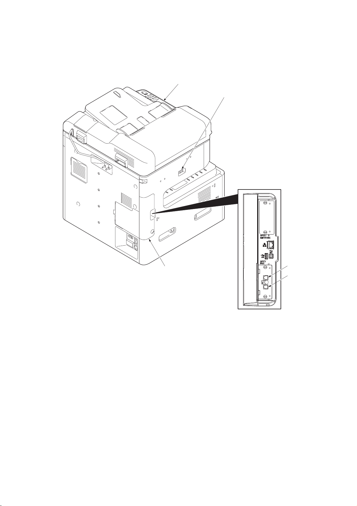
1-1-2 Parts names
2
4
5
3
1
1. Operation panel
2. Main power switch
3. Contoroler box cover
4. LINE connector
5. TEL connector
(1) Machine
5JR
Figure 1-1-1
Note that you cannot automatically receive FAX when turning the main power switch off.
To turn the power off, press the Power key on the operation panel.
1-1-4
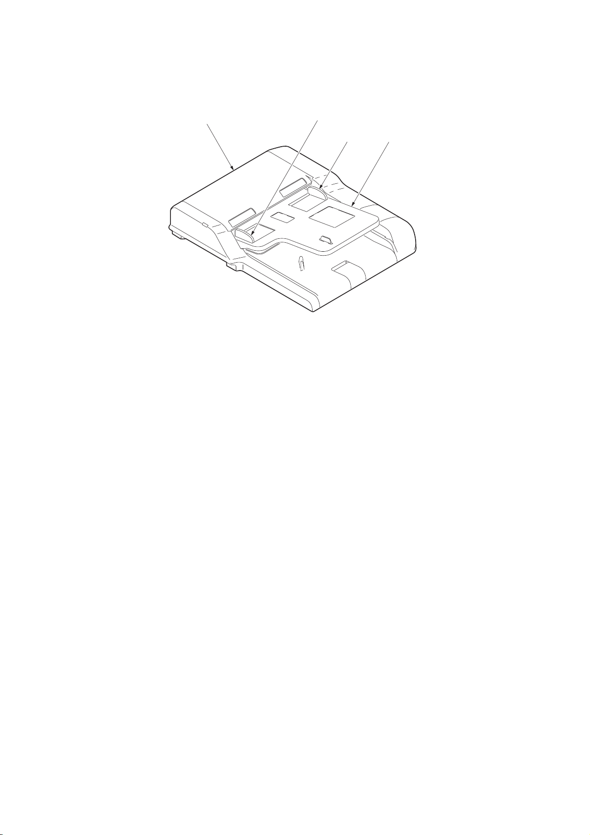
(2) Document processor
2
1
2
3
1. DP top cover
2. Paper width guides
3. Original table
5JR
Figure 1-1-2
1-1-5
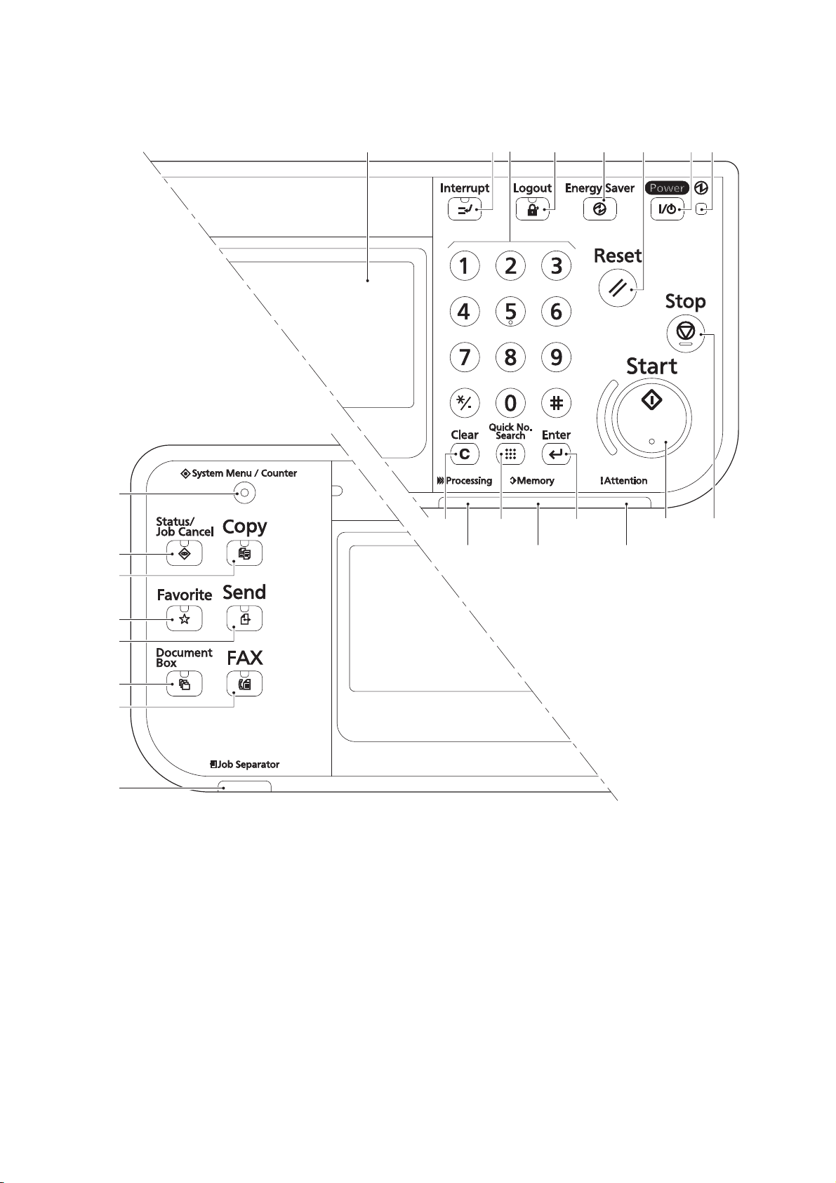
(3) Operation panel
1. Message display
2. Interlupt key / LED
3. Numeric keys
4. Logout key / LED
5. Enagy saver / LED
6. Reset key
7. Power key / LED
8. Main power LED
9. Clear key
10. Quick No.serch key
11. Enter key
12. Start key / LED
13. Stop key
14. System menu/Counter key
/ LED
15. Status/Job cancel / LED
16. Copy key / LED
17. Favorite key / LED
18. Send key / LED
19. Document box key / LED
20. FAX key / LED
21. Job separator LED
22. Processing LED
23. Memory LED
24. Attention LED
5JR
3
1
2 4 85 6
7
14
15
16
17
18
19
20
21
9 10
Figure 1-1-3
11
12
13
242322
1-1-6

5JR
1-2 Installation
1-2-1 Installation environment
Installation location (Be based on the machine establishment place.)
Avoid direct sunlight or bright lighting. Ensure that the photoconductor will not be exposed to direct sunlight or
other strong light when removing paper jams.
Avoid locations subject to high temperature and high humidity or low temperature and low humidity; an abrupt
change in the environmental temperature; and cool or hot, direct air.
Avoid places subject to dust and vibrations.
Choose a surface capable of supporting the weight of the machine.
Place the machine on a level surface (maximum allowance inclination: 1°).
Avoid air-borne substances that may adversely affect the machine or degrade the photoconductor, such as
mercury, acidic of alkaline vapors, inorganic gasses, NOx, SOx gases and chlorine-based organic solvents.
Select a well-ventilated location.
1-2-1
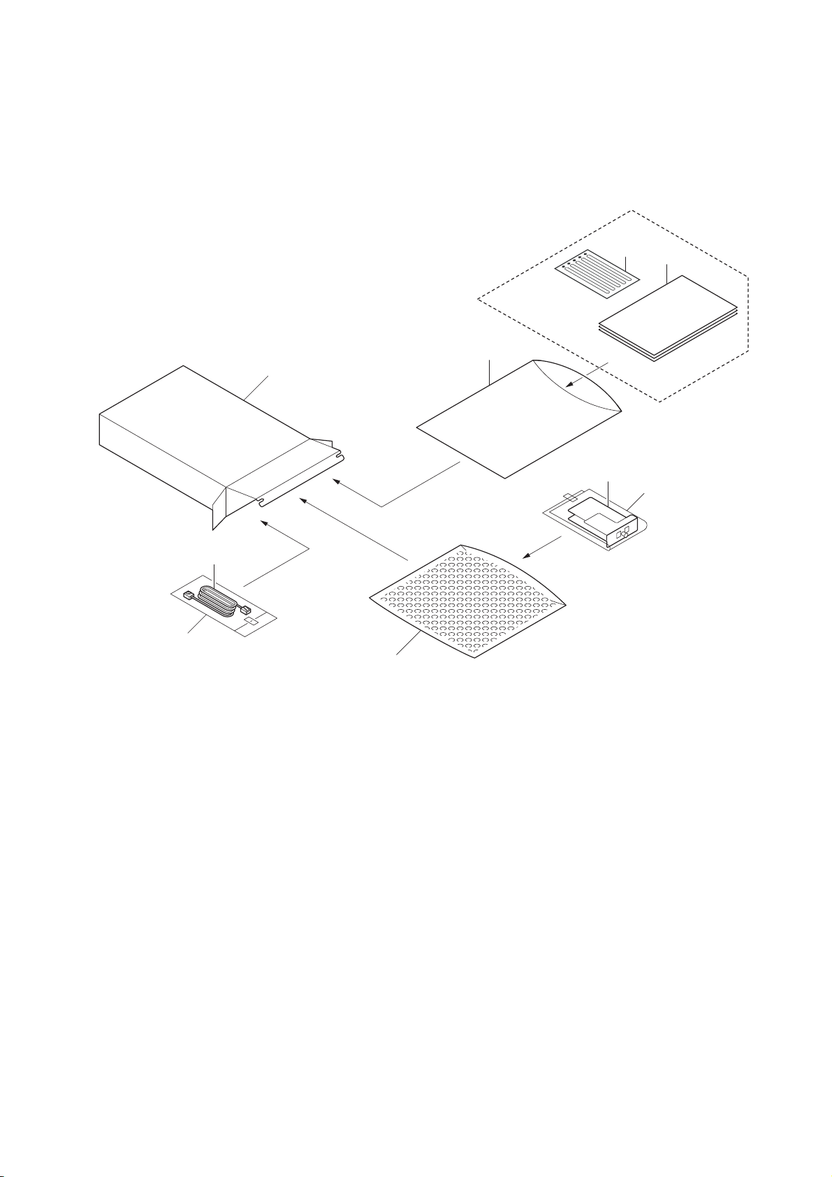
1-2-2 Unpacking
1. Fax assembly
2. Plastic bag
3. Air-padded bag
4. Modular cord
*1
5. Plastic bag
6. Outer case
7. Installation guide
8. Alphabet label
9. Plastic bag
*1: 120 V and Australian models only.
(1) Unpacking
5JR
8
7
9
6
1
2
4
5
3
Figure 1-2-1
Caution: See the Installation Guide for installation.
1-2-2
(2) Initialization procedure after installing the facsimile system
Code Destination Code Destination Code Destination
000 Japan 156 Singapore 253 Sweden
009 Australia 159 South Africa France
038 China 169 Thailand Austria
080 Hong Kong 181 U.S.A. Switzerland
084 Indonesia 242 South America Belgium
088 Israel 243 Saudi Arabia Denmark
097 Korea 253 CTR21 (European nations) Finland
108 Malaysia Italy Portugal
126 New Zealand Germany Ireland
136 Peru Spain Norway
137 Philippines U.K. 254 Taiwan
152 Middle East Netherlands
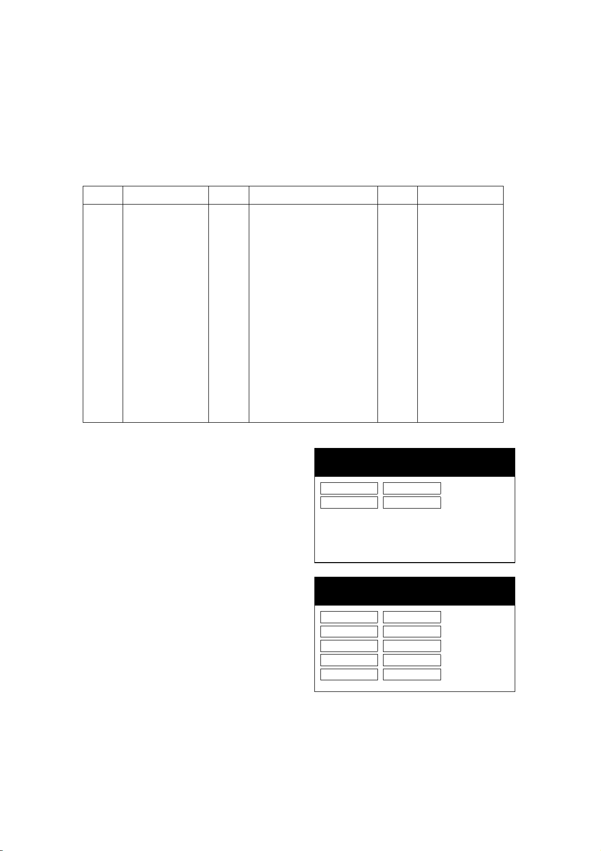
MAINTENANCE MODE
MAINTENANCE MODE ACTIVE. U600
Initialize: All Data
Country Code
XXX
OEM Code
YYY
MAINTENANCE MODE
MAINTENANCE MODE ACTIVE. U600
Initialize: All Data
Country Code
XXX
OEM Code
YYY
APL
****************
BOOT
****************
IPL
****************
1. Insert the machine power plug to the wall outlet and turn the main power switch on.
2. Enter 10871087 using the numeric keys. The machine enters maintenance mode.
3. Run maintenance item U600 using the cursor up/down keys or numeric keys.
4. Press [Execute] and then press the start key.
5. Select [Country Code] and enter a destination code using the numeric keys (refer to the destination code
list). Press the start key.
5JR
6. Select [OEM Code], enter the OEM
code (000) and then press the start key.
7. After initialization, the entered destination, OEM codes and ROM version are
displayed. A ROM version displays
three kinds, application, boot, and IPL.
8. After completing the installation, run the
communications test to confirm that the
fax system is operative.
1-2-3
Figure 1-2-2
 Loading...