

Page 1
FS-3820N
FS-3830N
Page Printers
Installation Guide
Page 2

Caution
No liability is assumed for any damage caused by improper installation.
Notice on Software
Software used with this printer must support the printer’s emulation mode. The printer is factory-set to emulate
the HP PCL 6. The emulation mode can be changed by following the procedures described in the Operation
Guide contained as an electronic file in the CD-ROM supplied with the printer.
Notice
The information in this manual is subject to change without notification. Additional pages may be inserted in
future editions. The user is asked to excuse any technical inaccuracies or typographical errors in the present
edition.
No responsibility is assumed if accidents occur while the user is following the instructions in this manual. No
responsibility is assumed for defects in the printer’s firmware (contents of its read-only memory).
This manual, any copyrightable subject matter sold or provided with or in connection with the sale of the page
printer, are protected by copyright. All rights are reserved. Copying or other reproduction of all or part of this
manual, any copyrightable subject matter without the prior written consent of Kyocera Mita Corporation is prohibited. Any copies made of all or part of this manual, any copyrightable subject must contain the same copyright notice as the material from which the copying is done.
Table of Contents
STEP 1 Unpacking ......................................................................... 1
STEP 2 Positioning the Printer ..................................................... 2
STEP 3 Installing the Toner Container ......................................... 3
STEP 4 Installing the Waste Toner Box........................................ 5
STEP 5 Connecting the Printer to the Computer ........................ 7
STEP 6 Connecting the Power Cord ............................................ 9
STEP 7 Adding Paper to the Paper Cassette and MP Tray....... 10
STEP 8 Turning the Power Switch On ........................................ 18
STEP 9 Printing a Status Page.................................................... 19
©2003, 2004 by KYOCERA MITA CORPORATION All rights reserved.
Revision 1.1 January 2004
Page 3
STEP
1
Unpacking
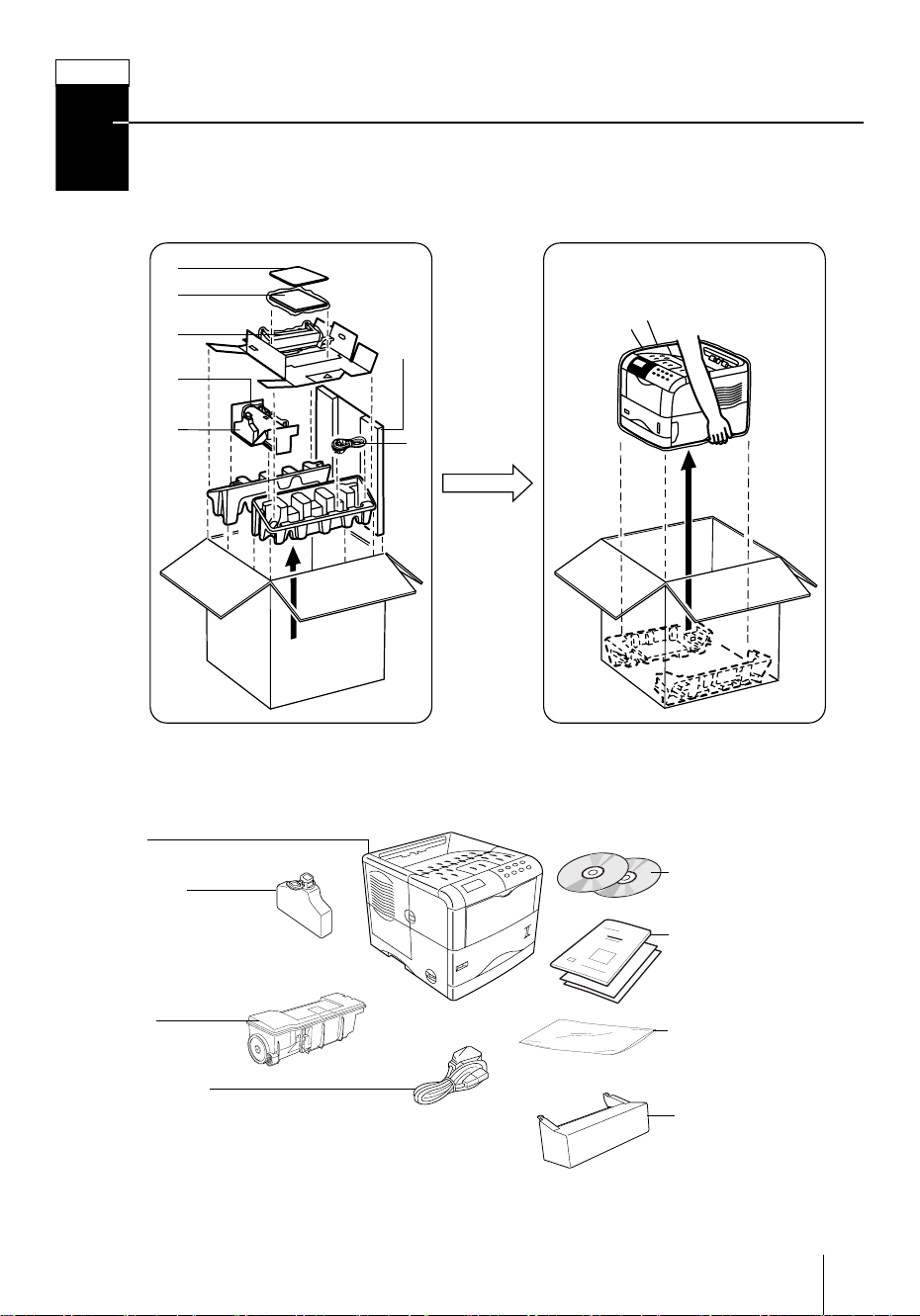
Carefully remove the printer and other items from the box. Check that nothing is missing against the list of shipped components below.
List of Shipped Components
(A)
(B)
(C)
(D)
(for
U.S.A.
only)
(E)
Printer
Waste Toner
Box (E)
Printer
(F)
CD-ROMs (B)
Installation Guide
[this booklet] and
other printed matter
(B)
To n e r
Container (D)
Power Cord (F)
Plastic Bag for
Developer Unit (A)
Dust Cover (C)
[for U.S.A. only]
1
Page 4
STEP
2
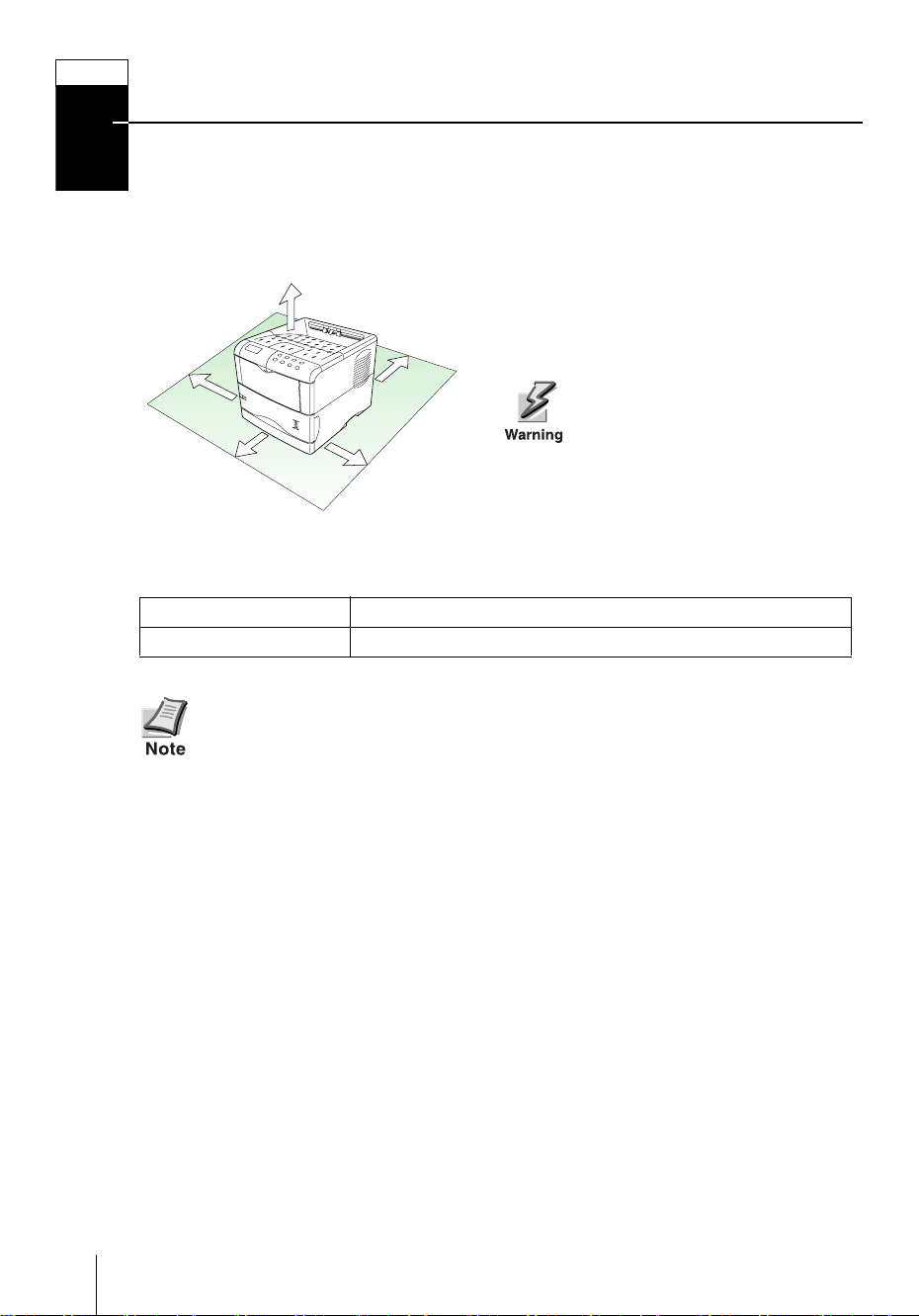
Positioning the Printer
Make sure that the place of installation meets the following requirements:
Clearance
30 cm (11-13/16 inches)
20 cm (7-7/8 inches)
[40 cm (15-3/4 inches) when the option
30 cm
(11-13/16
inches)
60 cm
(23-5/8
inches)
Environment
rear tray is installed]
25 cm
(9-7/8
inches)
Be sure to secure enough space
around the printer. Prolonged
use without sufficient clearance
may cause heat to build up
within the printer, resulting in
fire.
Te m p e r a t u r e
Humidity
Do not install the printer where temperature or humidity is outside the rec-
ommended range. Print quality may suffer and there will be an increased
chance of paper jams.
10 to 32.5 °C (50 to 90.5 °F), ideally about 23 °C (73.4 °F)
20 to 80 %, ideally 60 %
Places to Avoid
Avoid installing the printer in locations subject to:
• Direct drafts of hot or cold air
• Direct drafts from outside (Avoid locations near building entrances.)
• Sudden temperature or humidity changes
• Sources of high temperature, for example, near stoves or radiators
• Excessive dust
•Vibration
• Unstable surfaces and surfaces that are not level
• Ammonia or other harmful fumes (If you are planning to fumigate the room, or
make liberal use of insecticide, remove the printer first!)
• Excessive sunlight or humidity
• Lack of ventilation
• Low air pressure, e.g., elevations greater than 2000 meters (6500 feet) above
sea level
2
Page 5

STEP
3
Installing the Toner Container
Before you can use the printer for the first time, you must prepare it by installing the
toner container, waste toner box, and set up the interfacing with the computer.
Top Cover
1 Open the printer top cover all the way.
2 Take the toner container from the bag.
10 times or
more
Toner Container
Protective Seal
3 With the label side down, thoroughly
shake the toner container (in the direction of the arrow) ten times or more to
loosen and mix the toner inside.
4 Carefully remove the protective seal.
5 Install the toner container into the
printer.
3
Page 6
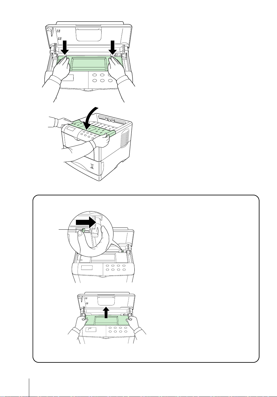
6 Push firmly on the top of the toner con-
tainer at the positions marked PUSH
HERE.
When the toner container fits into place,
it will lock with a clicking sound.
7 Close the top cover.
To remove the toner container
Lock Lever
Pull the lock lever (blue colored) to the
right and gently lift the toner container.
4
Page 7
STEP
4
Installing the Waste Toner Box
The waste toner box is supplied with the printer. The waste toner box must be installed
in the printer.
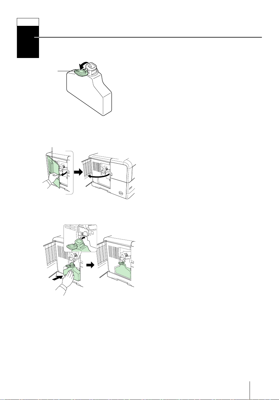
1 Open the cap of the waste toner box.
Cap
Waste Toner
Box
Left Cover
2 Open the left cover on the left side of the
printer.
3 Insert the waste toner box as shown in
the figure. The box will be locked when
it fits into place.
5
Page 8
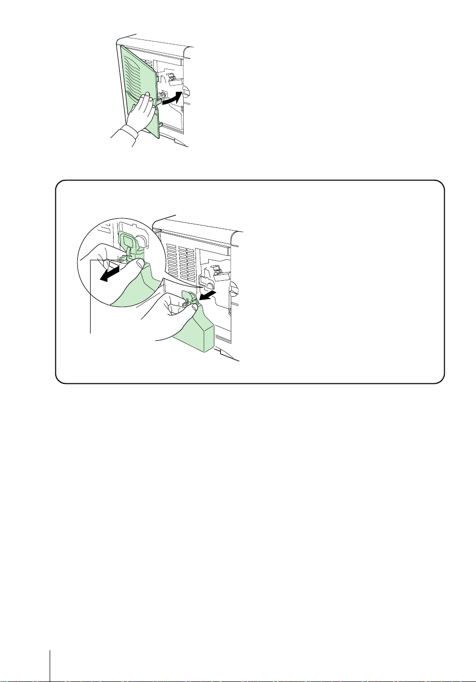
To remove the Waste Toner Box
4 Ensuring that it is correctly inserted,
close the left cover.
While holding the waste toner box,
press the lock lever and then gently
remove the waste toner box.
Lock Lever
6
Page 9
STEP
5
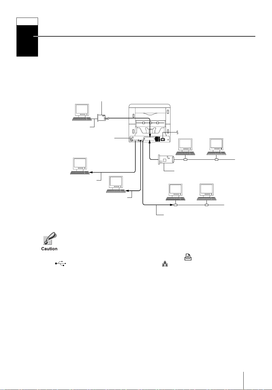
Connecting the Printer to the Computer
There are various ways of connecting the printer to the computer, such as through the
parallel interface connector, through the USB (Universal Serial Bus) interface connector, and through the network interface connector. In addition, a serial interface and a
second network interface are optionally available as well.
Printer Connections
Option Serial Interface
Board Kit (3.3 V DC)
Printer (Rear)
Serial Interface
Connector for option sorter
(See the option sorter’s
user’s manual.)
Parallel Interface
Power Supply
Network
Option Network Interface Card
(3.3 V DC)
USB Interface
Network
Network Interface
Before performing this step, be sure to turn off both the printer and the computer’s power switches and unplug the printer’s power plug from the power
outlet. Failure to do so may result in electrical shock.
The standard Centronics parallel interface connector ( ), USB interface connector ( ) and network interface connector ( ) are located on the rear of the
printer.
7
Page 10
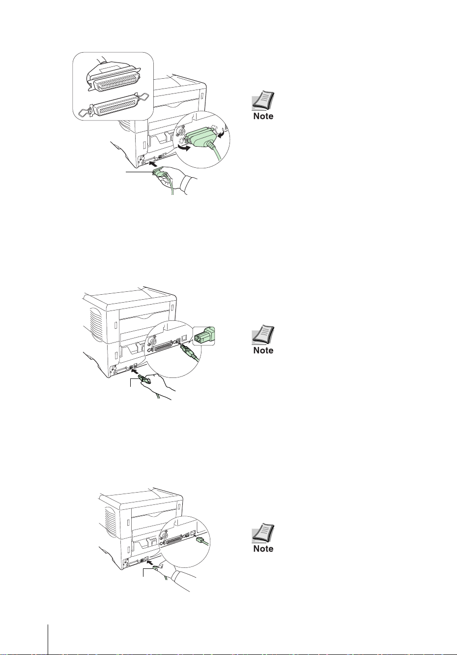
Parallel Interface Connection
1 Plug one end of the printer cable (not
included) into the parallel interface connector on the rear of the printer.
Clip
Parallel Printer
Cable
Clip
• Use a parallel printer cable
that complies with the
IEEE1284 standards.
• The printer will work best if it
is installed near the computer. The connecting cable
should be shielded and not be
longer than 3 meters (10 feet).
2 Close the clips on both sides to fix the
connector in place.
Plug the other end of the printer cable
into the computer’s parallel interface
connector.
USB (Universal Serial Bus) Interface Connection
1 Plug one end of the USB cable into the
USB interface connector on the rear of
the printer.
• Use a cable that complies
with Revision 2.0 of USB standard. (a rectangular Type A
plug or a square Type B plug).
8
USB Cable
2 Plug the other end of the USB cable into
the computer’s USB interface connector.
Network Interface Connection
1 Plug one end of the network cable (not
included) into the network interface
connector on the rear of the printer.
2 Plug the other end of the network cable
Network Cable
into the network hub.
• The connecting cable should
be shielded and not be longer
than 5 meters (16 feet).
Use an Ethernet cable (10BaseT or 100Base-TX) as the network cable.
Page 11
STEP
6
Connecting the Power Cord
This section describes the procedure for connecting the power cord and various cautions.
Notes on Power Supply
• Install the printer near an AC wall outlet, preferably one that can be used for
the printer alone.
• Only use this printer with the supply voltage indicated on the serial number
label attached to the printer’s rear panel.
• If an extension cord is used, the total length of the power cord plus extension
should be 5 meters (16 feet) or less.
Power Requirements
Voltage
Frequency
Current capacity
120 V (U.S.A. and Canada), 220 to 240 V (European countries,
and the Asia Pacific region), ±10 % at each voltage
60 Hz (120 V) ±2 %, 50/60 Hz (220 to 240V) ±2 %
8.0 A at 110/120 V, or 4.0 A at 220 to 240 V
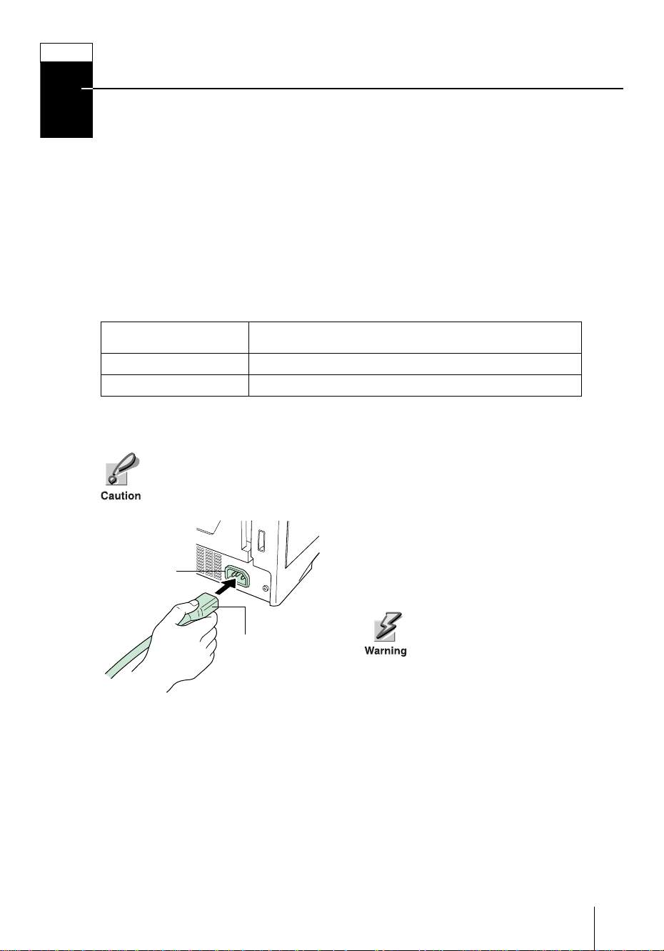
T o Connect the Power Cord
• Be sure the printer’s power switch is turned off.
• Only use the power cord supplied with the printer .
1 Plug the power cord into the power cord
Power Cord
Connector
Power Cord
2 Connect the other end of the power cord
connector on the rear of the printer.
into a power outlet.
Be sure to connect to a 3-wire
grounded power strip.
9
Page 12

STEP
7
Adding Paper to the Paper Cassette and MP
Tray
The paper cassette can accommodate A5 to A4/Letter and Legal (for U.S.A. only) size
paper and can hold approximately 500 sheets. The MP (Multi Purpose) tray can
accommodate the various paper sizes and can hold approximately 100 sheets of
paper.
Paper sizes that are not standard sizes (other sizes) but within the size limitations
can also be loaded into the cassette. When loading other sizes into the cassette, the
size must be input into the printer on the operator panel (Refer to the Operation
Guide [PDF file] provided on the CD-ROM). Standard size paper settings are indicated as fixed positions in the cassette.
The following paper weights can be used with the printer.
Paper source Paper weight
Paper cassette 60 to 105 g/m²
MP tray 60 to 200 g/m²
The edges of paper are sharp. When loading paper, be careful not to cut
your hand on the paper.
Paper cassette
Standard paper sizes are attached to the inside of the paper cassette as shown in
the following figure. Align the paper guides and paper stopper to the paper size
you want to print on as described on the next page.
10
A4
Letter
B5
A5
Page 13

Paper Cassette
Bottom Plate
1 Pull the paper cassette all the way out of
the printer.
2 Push the bottom plate down until it
locks.
Standard paper sizes are attached to
the inside of the paper cassette as
shown in the following figure. In the
paper cassette for U.S.A., Legal size
indication is also attached.
11
Page 14

Paper Size Dial Paper Size Window
Release
3 Turn the paper size dial so that the size
of the paper you are going to use
appears in the paper size window.
When the paper size dial is set
to OTHER the paper size must
be set into the printer on the
operator panel. See the Opera-
tion Guide (PDF file) provided
on the CD-ROM.
4 Adjust the position of the paper guides
located on the left and right sides of the
paper cassette. Pull the release lever on
the left side guide and slide to the
desired paper size.
Release
Paper Guides
Paper
Stopper
5 Adjust the position of the paper stopper
located at the rear of the paper cassette.
Pull the release lever and slide the
paper stopper to the desired paper size.
When shipped from the factory, the
paper cassette is set to A4 size.
When using other size paper, move the
paper guides and paper stopper all the
way out, insert the paper, then adjust
the paper guides and paper stopper to
the size of the paper. Adjust them so
that they are in light contact with the
paper.
12
Page 15

Fan the media (paper/transparencies), then tap it on a level
surface to avoid media jams or
skewed printing.
6 Slide the paper into the paper cassette.
Load Limit Load Limit
Clip Clip
• Do not load more paper than
will fit under the load limits on
the paper guides.
• The paper cassette will hold
approximately 500 sheets of
paper with a 80 g/m² (21 lb.)
basis weight, or with a thickness of 0.11 mm.
7 Set the stack of paper so that it is under
the clips as shown.
13
Page 16

Paper Gauge
8 Insert the paper cassette into the slot in
the printer. Push it straight in as far as
it will go.
There is a paper gauge on the right
side of the front of the paper cassette
to indicate the remaining paper
supply. When paper is exhausted, the
pointer
will go down to the level of
(empty).
9 If you have installed a paper cassette
that can hold the Legal size paper,
install the dust cover at the back of the
printer. (The Legal size cassette and the
dust cover are supplied for U.S.A. only.)
14
Removing the Dust Cover
Page 17

MP (Multi Purpose) tray
MP Tray
1 Pull the MP tray towards you until it
stops.
2 Pull out the subtray.
A4
LTR
Paper Guides
B5
A5
Load Limit
3 Adjust the position of the paper guides
on the MP tray. Standard paper sizes
are attached to the MP tray. For standard paper sizes, slide the guides to the
position marked correspondingly.
4 Align the paper with the paper guides
and insert as far as it will go.
Do not load more paper than
will fit under the load limits on
the inside of the MP tray.
15
Page 18
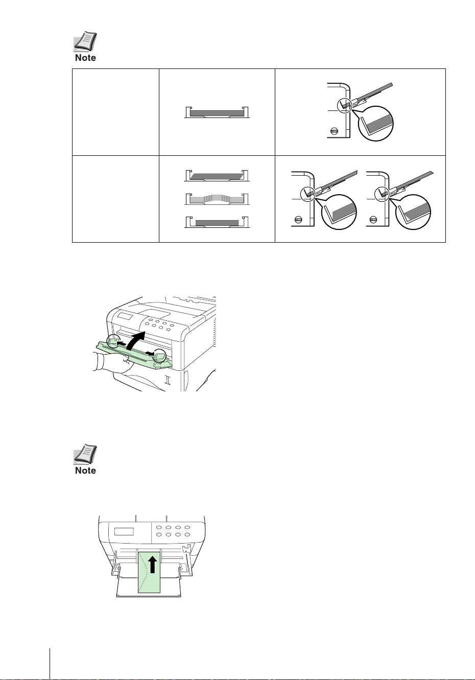
If the paper is considerably curled in one direction, for example, if the
paper is already printed on one side, try to roll the paper in the opposite
direction to counteract the curl. Printed sheets will then come out flat.
Correct
Incorrect
To Close the MP Tray
Before closing the MP Tray, ensure the
subtray is pushed back in, and the
paper guides are opened as far as they
will go.
16
Envelopes
Envelopes should be fed in the face-up position, right edge first.
• Test a sample envelope on the printer and check that printing quality is
satisfactory before purchasing.
• To avoid trouble, we recommend that envelopes be delivered face-up
using the option rear tray. Refer to next page.
Some types of envelopes are not suitable
for printing. For details on suitable
types of envelopes, see the Operation
Guide contained as a PDF file in the CDROM supplied with the printer.
Page 19

Installing the Option Rear Tray
Use the rear tray when you wish paper to be stacked with the printed side facing
up (reverse order), or when you are printing on envelopes, postcards, transparencies, or thick paper.
This rear tray is a separate option.
Legal Size
A4 Size
Letter Size
Paper Stopper
Rear Tray
17
Page 20

STEP
8
Turning the Power Switch On
This section describes the procedure for turning on the printer’s power.
During start-up, the language for the message display and status page of this printer
can be selected from English, French, German, Italian, Dutch, Spanish, and Portuguese.
The default message language is English. For how to change the message language to another, refer to the Selecting a Message Language section.
1 Switch on the printer’s power. The mes-
sage display should indicate Self
test.
If the indicator does not light,
check that previous steps were
performed properly.
When the printer is first switched
on after installation, there will be a
delay of approximately 8 minutes
Power Switch
before the printer gets ready to
print as the developer unit needs to
be filled with toner. During this
period, the message display shows
Please wait (Adding toner).
2 Wait until the READY ( ) indicator is
Ready
--- A4 PLAIN
also lit and the message display indicates Ready. The printer is ready to
print.
Selecting a Message Language
The default message language is English. To change the message language to
another, follow the procedure described below. If required, your dealer can download major languages other than English, French, German, Italian, Dutch, Spanish, and Portuguese to your printer. Please contact your dealer.
1 While pressing the ENTER key, turn the
GO
CANCEL MENU ENTER
Please wait
?
power switch ON ( l ). Keep pressing the
ENTER key until the message display
indicates Please wait (approximately
1 minute). The message display should
indicate Self test.
2 When the message display shows
Please wait, release the ENTER key.
18
Page 21

STEP
9
3 The message display indication
MSG language
? English
changes to that shown on the left and ?
flashes.
4 Press the or key repeatedly until
or
ENTER
the message display shows the desired
language and then press the ENTER
key.
If you do not wish to change the setting,
press the CANCEL key.
5 The READY ( ) indicator on the oper-
ator panel lights and the printer gets
ready to print.
Printing a Status Page
To test the printer, print a status page indicating factory settings.
1 Press the MENU key on the operator
panel.
MENU
or
Print
Status Page
ENTER
2 times press
2 Press the or key repeatedly until
the message display shows
Print Status Page.
3 Press the ENTER key twice. The mes-
sage display indicates Processing
during printing of the status page, then
returns to Ready.
If the status page prints correctly,
printer setup is complete. For details on
using the printer, refer to the Operation
Guide contained as a PDF file in the CDROM supplied with the printer.
19
Page 22

Correcting a Paper Jam
If a paper jam occurs while you are printing, remove the jammed paper as
described below. After you have removed the jammed paper, open and close the
top cover or the paper transfer unit.
When pulling the paper, pull it gently so as not to tear it. Torn pieces of
paper are difficult to remove and may be easily overlooked, deterring the
jam recovery.
Jam at the Rear Cover
1 While pulling the paper transfer unit release lever (green colored), pull out the
paper transfer unit.
2 Open the rear cover and remove the jammed paper as shown in the figure.
Paper Transfer Unit Release
Lever (green colored)
20
Paper Transfer Unit
Rear Cover
Page 23

Jam Inside the Printer
1 While pulling the paper transfer unit release lever (green colored), pull out the
paper transfer unit.
2 If paper is jammed before the registration roller, remove it as shown in A.
If paper is jammed under the registration roller, remove it as shown in B.
A
Paper Transfer Unit Release
Lever (green colored)
Registration Roller
Paper Transfer
Unit
B
Registration Roller
21
Page 24

FCC statement for users in the United States
This device complies with Part 15 of the FCC Rules. Operation is subject to the following two conditions: (1) This
device may not cause harmful interference, and (2) this device must accept any interference received, including
interference that may cause undesired operation.
■ Note
This equipment has been tested and found to comply with the limits for a Class B digital device, pursuant to
Part 15 of the FCC Rules. These limits are designed to provide reasonable protection against harmful interference in a residential installation. This equipment generates, uses, and can radiate radio frequency energy and,
if not installed and used in accordance with the instructions, may cause harmful interference to radio communications. However, there is no guarantee that interference will not occur in a particular installation. If this
equipment does cause harmful interference to radio or television reception, which can be determined by turning
the equipment off and on, the user is encouraged to try to correct the interference by one or more of the following
measures:
• Reorient or relocate the receiving antenna.
• Increase the separation between the equipment and receiver.
• Connect the equipment into an outlet on a circuit different from that to which the receiver is connected.
• Consult the dealer or an experienced radio/TV technician for help.
Changes or modifications not expressly approved by the manufacturer for compliance could void the user’s
authority to operate the equipment. Shielded circular cable should be used for interfacing with the computer.
■ Caution to user
Any modification without prior permission may cause harmful interference.
If any modification/change is introduced to this equipment without prior permission, Kyocera Mita as the man-
ufacturer cannot guarantee compliance with FCC rules. To use equipment which does not comply with FCC
rules is prohibited. The printer may be optionally installed with the following units:
■ Options Conforming to the Class B limits
• DU-61 Duplexer
• SO-60 Sorter
• PF-60 Paper Feeder (500 sheets)
Warning: FCC Regulations state that any unauthorized changes or modifications to this equipment not
expressly approved by the manufacturer could void the user’s authority to operate the equipment.
22
Page 25

■ Caution labels
The labels shown are affixed to the printer.
Label inside the printer (Laser radiation warning)
(European/Pacific countries)
Label on the printer’s rear panel
Label inside the rear
(U.S.A/Canada)
Ozone concentration
The printers generate ozone gas (O3) which may concentrate in the place of installation and cause an unpleasant
smell. To minimize concentration of ozone gas to less than 0.1 ppm, we recommend you not to install the printer
in a confined area where ventilation is blocked.
IMPORTANT SAFEGUARDS
1. Read all of these instructions and save these instructions for later use.
2. Unplug this product from the wall outlet before cleaning.
3. Do not use this product near water.
4. Do not place this product on an unstable cart, stand, or table. The product may fall, causing serious damage to
the product.
5. Slots and openings in the cabinet and the back are provided for ventilation to ensure reliable operation of the
product and to protect it from overheating, these openings must not be blocked or covered. The openings should
never be blocked by placing the product on a bed, sofa, rug, or other similar surface. This product should never
be placed near or over a radiator or heat register. This product should not be placed in a built-in installation
unless proper ventilation is provided.
6. This product is equipped with a 3-wire grounding type plug, a plug having a third (grounding) pin. This plug
will only fit into a grounding-type power outlet. This is a safety feature. If you are unable to insert the plug into
the outlet, contact your electrician to replace your obsolete outlet. Do not defeat the purpose of the groundingtype plug.
7. Do not allow anything to rest on the power cord. Do not locate this product where persons will walk on the cord.
8. If an extension cord is used with this product, make sure that the total of the ampere ratings on the products
plugged into the extension cord do not exceed the extension cord ampere rating.
23
Page 26

9. Never push objects of any kind into this product through cabinet slots as they may touch dangerous voltage
points or short out parts that could result in a risk of fire or electric shock. Never spill liquid of any kind on the
product.
10. Except as explained elsewhere in User’s Manual, do not attempt to service this product yourself. Removing
covers may expose you to dangerous voltage points or other risks. Refer all servicing in those compartments to
service personnel.
11. Unplug this product from the wall outlet and refer servicing to qualified service personnel under the following
conditions:
A- When the power cord or plug is damaged or frayed.
B- If liquid has been spilled into the product.
C- If the product has been exposed to rain or water.
D- If the product does not operate normally when the operating instructions are followed. Adjust only
those controls that are covered by the operating instructions since improper adjustment of other controls may result in damage and will often require extensive work by a qualified technician to restore
the product to normal operation.
E- If the product has been dropped or the cabinet has been damaged.
Canadian Department of Communications compliance statement
This Class B digital apparatus complies with Canadian ICES-003.
Avis de conformité aux normes du ministère des Communications du
Canada
Cet appareil numérique de la classe B est conforme à la norme NMB-003 du Canada.
ISO 7779
Maschinenlärminformationsverordnung 3. GSGV, 18.01.1991: Der höchste Schalldruckpegel beträgt 70 dB(A)
oder weniger gemäß ISO 7779.
CE Marking Directive
According to Council Directive 89/336/EEC and 73/23/EEC
Manufacturer’s name: Kyocera Mita Corporation, Tamaki Plant
Manufacturer’s address: 704-19 Nojino, Tamaki-Cho, Watarai-Gun, Mie-Ken 519-0497, Japan
declares that the product
Product name: Page Printer
Model number: FS-3820N/FS-3830N (as tested with the enhancement optional unit: PF-60, DU-61, and SO-60)
Conforms to the following product specifications.
EN 55 022:1998 Class B
EN 61 000-3-2:1995
EN 61 000-3-3:1995
EN 55 024:1998
EN 60 950:2000
EN 60 825-1:1994+A1+A2
The manufacturer and its merchandising companies retain the following technical documentation in anticipation of the inspection that may be conducted by the authorities concerned.
User’s instruction that conforms to the applicable specifications
Technical drawings
Descriptions of the procedures that guarantee the conformity
Other technical information
24
Page 27

Declaration of Conformity (Australia)
Manufacturer’s name: Kyocera Mita Corporation, Tamaki Plant
Manufacturer’s address: 704-19 Nojino, Tamaki-Cho, Watarai-Gun, Mie-Ken 519-0497, Japan
declares that the product
Product name: Page Printer
Model number: FS-3820N/FS-3830N (as tested with the enhancement optional units: PF-60, DU-61, and SO-60)
Description of device: This Page Printer Model FS-3830N is the 33 ppm (FS-3820N is the 28 ppm); A4 size and
utilized plane paper; laser; dry toner etc. The printer can be equipped with several
as a paper feeder as PF-60, a duplexer as DU-61, a sorter as SO-60 etc.
Conforms to the following product specifications.
AS/NZS 3548: 1995 (EN 55 022:1994 Class B)
IEC60950 (EN 60 950:2000)
IEC60825-1 (EN 60 825-1:1994+A11+A2)
The manufacturer and its merchandising companies retain the following technical documentation in anticipation of the inspection that may be conducted by the authorities concerned.
User’s instruction that conforms to the applicable specifications
Technical drawings
Descriptions of the procedures that guarantee the conformity
Other technical information
Kyocera Mita Australia Pty., Ltd.
6-10 Talavera Road, North Ryde, NSW, 2113, Australia
Phone: +61 2-9888-9999
Fax: +61 2-9888-9588
enhancement optional units
Declaration of Conformity (U.S.A.)
Model Number:
Trade Name: Kyocera
Responsible Party: Kyocera Mita America Inc.
Address: 225 Sand Road PO Box 40008 Fairfield, New Jersey 07004-0008, U.S.A.
Telephone number: (973) 808-8444
Fax number: (973) 882-6000
Manufacturer’s name: Kyocera Mita Corporation, Tamaki Plant
Manufacturer’s address: 704-19 Nojino, Tamaki-Cho, Watarai-Gun, Mie-Ken 519-0497, Japan
This device complies with Part 15 of the FCC Rules, Operation is subject to the following two conditions: (1) This
device may not cause harmful interference, and (2) this device must accept any interference received, including
interference that may cause undesired operation.
The manufacturer and its merchandising companies retain the following technical documentation in anticipation of the inspection that may be conducted by the authorities concerned.
User’s instruction that conforms to the applicable specifications.
Technical drawings.
Descriptions of the procedures that guarantee the conformity.
Other technical information.
Laser Printer
PF-60, DU-61, SO-60.)
FS-3820N/FS-3830N
(as tested with enhancement optional units:
Kyocera Mita America Inc.
Disclaimer
We shall have no liability or responsibility to customers or any other person or entity with respect to any liability,
loss or damage caused or alleged to be caused directly or indirectly by equipment sold or furnished by us, including
but not limited to, any interruption of service, loss of business or anticipatory profits, or consequential damages
resulting from the use or operation of the equipment or software.
25
Page 28
Prolonged Non-Use and Moving the Printer
■ Prolonged Non-use
If you ever leave the printer unused for a long period of time, remove the power cord from the wall outlet.
We recommend you consult with your dealer about the additional actions you should take to avoid possible dam-
ages that may occur when the printer is used next time.
■ Moving the Printer
When you move the printer:
• Move it gently.
• Keep it as level as possible, to avoid spilling toner inside the printer as
shown in the figure.
• The handhold on the right side of the printer doubles as the memory
card slot. Be sure to remove the memory card first, if inserted, before
lifting or moving the printer.
• Be sure to remove all the option units such as the sorter and duplexer
before moving the printer.
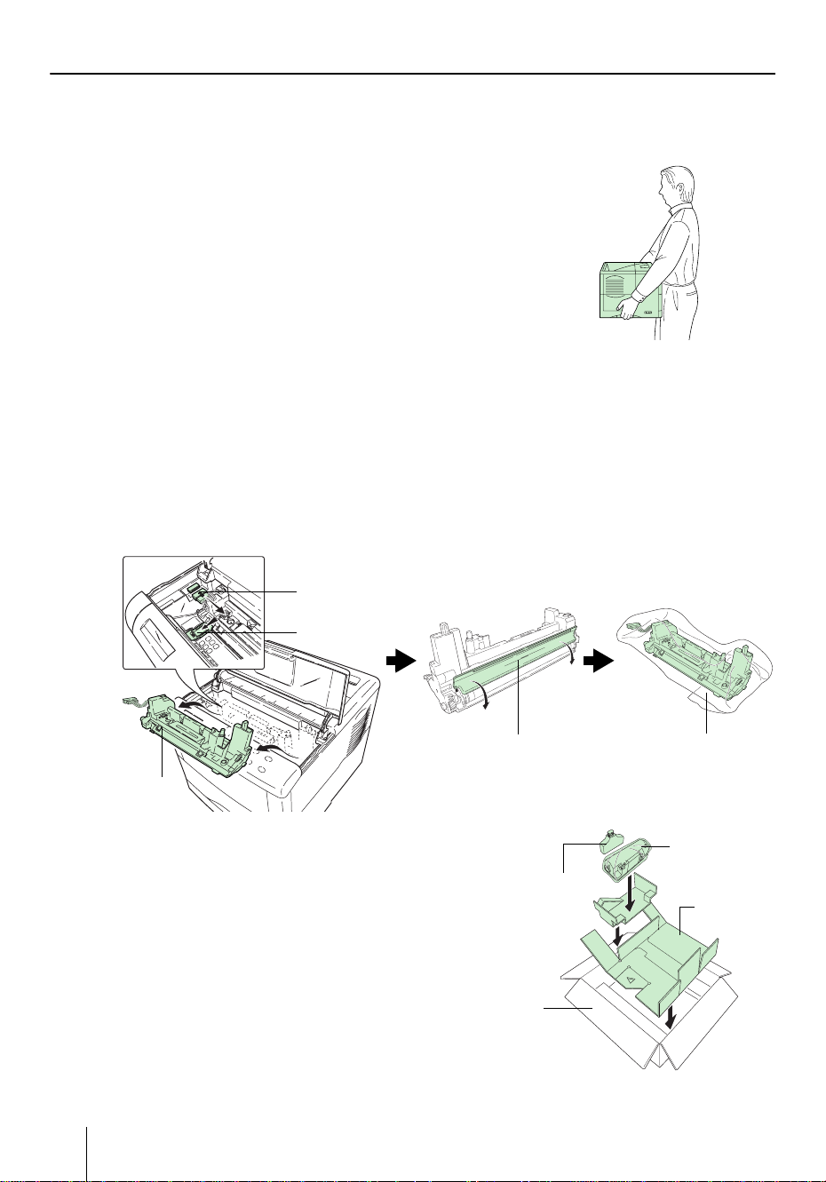
If you need to move the printer to another location, remove the toner container, waste toner box, and developer
unit. The procedure for removing these is as follows:
1 Remove the toner container and waste toner box from the printer. Put the toner container into the
plastic bag in which it was supplied to prevent spilling of toner. Close the cap of the waste toner
box tightly.
2 Disconnect the connector of the developer unit from the printer and while pulling the developer
unit release lever, remove the developer unit from the printer (1). Close the protect cover on the
developer unit (2) and put the developer unit into the supplied plastic bag (3).
(1)
Remove the developer unit.
(2)
Close the protect cover.
(3)
Put the developer unit.
1. Disconnect
2. Pull
Developer
Unit
3 Put the printer into the box in reverse order of the
unpacking procedure (Refer to STEP 1 Unpacking).
Position the pad as shown in the figure, then place the
toner container and waste toner box.
Printer Packing
Carton
Protect Cover
Waste Toner
Box
Plastic bag (supplied)
Toner Container
Pad
26
Page 29

4 Push the center as shown in the figure to make space for
the developer unit.
5 Put the developer unit into that space.
To reinstall the developer unit into the printer, use the reverse procedure of the above.
ENERGY STA R
®
As an ENERGY STAR Partner, we have determined that this product meets the
E
NERGY STAR guidelines for energy efficiency.
The basic objective of the E
lution by encouraging the manufacture and sale of equipment that uses energy
more efficiently.
This printer is equipped with a sleep timer function that conforms with the standards of the E
the amount of electrical power consumed by the printer. For maximum power
savings, turn off the printer’s power supply when not using the printer for
extended periods of time.
For details on the sleep timer function and printer power consumption, refer to
the CD-ROM instruction manual provided with the printer.
Initial settings of the sleep timer function and power saved using the sleep timer
function:
Model name Initial sleep mode setting
FS-3820N 15 minutes (30 minutes) 13 W (30 W)
FS-3830N 15 minutes (60 minutes) 13 W (40 W)
NERGY STAR Program. This function makes it possible to reduce
NERGY STAR Program is to reduce environmental pol-
Power consumption in sleep
mode
( ): E
NERGY STAR program guideline
Developer Unit
Group for Energy Efficient Appliances (GEEA)
The goal of GEEA is efficient use of energy. This product has a high-efficiency
profile and meets the criteria for receiving the GEEA-Label.
Model name Initial sleep mode setting
FS-3820N 15 minutes (30 minutes) 0 W (1 W) 13 W (15 W)
FS-3830N 15 minutes (60 minutes)
Power consumption
Power off Sleep mode
( ): GEEA criteria
27
Page 30
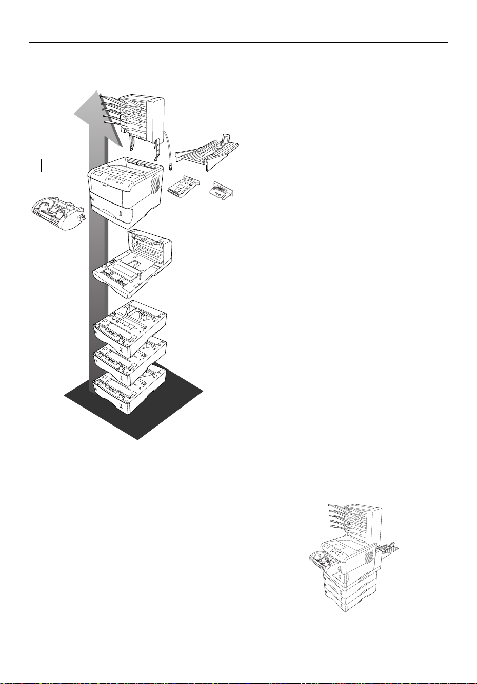
Options
1
The following options are available for the printer.
Sorter
(SO-60)
Rear Tray
2
Printer
Network
3
Interface Card
(3.3 V DC)
5
e
a
r
l
l
Duplexer
(DU-61)
6
f
o
i
t
a
or
Serial Interface
Board Kit
(IB-11)
Paper feeder
(PF-60)
n
o
4
Envelope
feeder
(EF-60)
d
r
O
t
s
n
I
1Sorter (SO-60)
Equipped with five trays each with 200 sheets
capacity. Performs sorting, collating, and mailbox
function. Attaches to the top of the printer.
2Rear Tray
It attaches to the rear of the printer.
3 Network Interface Card (IB-20/21E/22)
Insert the card into the option interface slot at the
rear of the printer. The printer can be used on network environments including Windows, Macintosh, UNIX, NetWare, etc.
Serial lnterface Board Kit (IB-11)
Connect to the computer’s serial printer port with
a serial cable.
4 Envelope Feeder (EF-60)
Holds more envelopes at a time than the MP tray.
This envelope feeder can be attached to t he front of
the printer after the MP tray has been removed.
5 Duplexer (DU-61)
Performs duplex printing for short edge and long
edge binding. Attaches to the bottom of the printer.
6 Paper Feeder (PF-60)
Holds approximately 500 sheets of A5 to A4/Letter
and Legal size paper. Up to three paper feeders can
be attached to the bottom of the printer unit.
Other Options
• Paper Cassette (PC-60LG)
Holds A5 to A4/Letter and Legal size paper.
• Bulk Paper Feeder (PF-8E)
Holds approximately 2,000 sheets of 76 to 216 mm
(3 to 8-1/2") × 148 to 305 mm (5-13/16 to 12") size
paper. This bulk paper feeder can be attached to
the front of the printer after the MP tray has been
removed, but can only be installed on the
FS-3830N.
• Memory DIMM, CompactFlash™ card,
Microdrive™ (Hard Disk Unit)
See your dealer for purchasing information of
these optional devices that are best suited for use
with this printer.
Printer combined with options
28
Page 31

Regarding Trademarks
PRESCRIBE is a registered trademark of Kyocera Corporation. KPDL and KIR (Kyocera Image Refinement)
are trademarks of Kyocera Mita Corporation.
Hewlett-Packard, PCL, and PJL are registered trademarks of Hewlett-Packard Company. Centronics is a trade
mark of Centronics Data Computer Corp. PostScript is a registered trademark of Adobe Systems Incorporated.
Adobe and Acrobat are trademarks of Adobe Systems Incorporated.
This Kyocera Mita page printer uses PeerlessPrintXL to provide the HP LaserJet compatible PCL 6 language
emulation. PeerlessPrintXL is a trademark of The Peerless Group, Redondo Beach, CA 90278, U.S.A.
This product was developed using the Tornado™ Real Time Operating System and Tools from Wind River Systems.
This product contains UFST
™
and MicroType® from Agfa Monotype Corporation.
ENERGY STAR is a U.S. registered mark.
IBM Program License Agreement
The device you have purchased contains one or more software programs ("Programs") which belong to international business machines corporation ("IBM"). This document defines the terms and conditions under which the
software is being licensed to you by IBM. If you do not agree with the terms and conditions of this license, then
within 14 days after your acquisition of the device you may return the device for a full refund. If you do not so
return the device within the 14 days, then you will be assumed to have agreed to these terms and conditions.
The Programs are licensed not sold. IBM, or the applicable IBM country organization, grants you a license for
the Programs only in the country where you acquired the Programs. You obtain no rights other than those
granted you under this license.
The term "Programs" means the original and all whole or partial copies of it, including modified copies or portions merged into other programs. IBM retains title to the Programs. IBM owns, or has licensed from the owner,
copyrights in the Programs.
1. License
Under this license, you may use the Programs only with the device on which they are installed and transfer possession of the Programs and the device to another party.
If you transfer the Programs, you must transfer a copy of this license and any other documentation to the other
party. Your license is then terminated. The other party agrees to these terms and conditions by its first use of
the Program.
You may not:
1) use, copy, modify, merge, or transfer copies of the Program except as provided in this license;
2) reverse assemble or reverse compile the Program; or
3) sublicense, rent, lease, or assign the Program.
2. Limited Warranty
The Programs are provided "AS IS."
There are no other warranties covering the programs (or conditions), express or implied, including, but not lim-
ited to, the implied warranties of merchantability and fitness for a particular purpose.
Some jurisdictions do not allow the exclusion of implied warranties, so the above exclusion may not apply to you.
3. Limitation of Remedies
IBM’s entire liability under this license is the following;
1) For any claim (including fundamental breach), in any form, related in any way to this license, IBM’s liability
will be for actual damages only and will be limited to the greater of:
a) the equivalent of U.S.$25,000 in your local currency; or
b) IBM’s then generally available license fee for the Program
This limitation will not apply to claims for bodily injury or damages to real or tangible personal property for
which IBM is legally liable.
IBM will not be liable for any lost profits, lost savings, or any incidental damages or other economic consequential damages, even if IBM, or its authorized supplier, has been advised of the possibility of such damages. IBM
will not be liable for any damages claimed by you based on any third party claim. This limitation of remedies
also applies to any developer of Programs supplied to IBM. IBM’s and the developer’s limitations of remedies
are not cumulative. Such developer is an intended beneficiary of this Section. Some jurisdictions do not allow
these limitations or exclusions, so they may not apply to you.
29
Page 32

4. General
You may terminate your license at any time. IBM may terminate your license if you fail to comply with the terms
and conditions of this license. In either event, you must destroy all your copies of the Program. You are responsible for payment of any taxes, including personal property taxes, resulting from this license. Neither party may
bring an action, regardless of form, more than two years after the cause of action arose. If you acquired the Program in the United States, this license is governed by the laws of the State of New York. If you acquired the
Program in Canada, this license is governed by the laws of the Province of Ontario. Otherwise, this license is
governed by the laws of the country in which you acquired the Program.
Important Note on the Interface Connectors
Be sure to turn off printer power before connecting or disconnecting an interface cable to the printer. For protection against static discharge which may be applied to the printer’s internal electronics through the interface
connector(s), keep any interface connector which is not in use capped using the protective cap supplied.
Note: Use shielded interface cable.
Safety Information
■ Laser Safety
This printer is certified as a Class 1 laser product under the U.S. Department of Health and Human Services
(DHHS) Radiation Performance Standard according to Radiation Control for Health and Safety Act of 1968.
This means that the printer does not produce hazardous laser radiation. Since radiation emitted inside the
printer is completely confined within protective housings and external covers, the laser beam cannot escape
from the printer during any phase of user operation.
■ Laser Notice
This printer is certified as a Class I laser product conforming to the requirements of IEC 825.
DANGER: LASER RADIATION WHEN OPEN. AVOID DIRECT EXPOSURE TO BEAM.
CAUTION: Use of controls or adjustments or performance of procedures other than those specified herein may
result in hazardous radiation exposure.
30
Page 33

This page intentionally left blank.
Page 34

This page intentionally left blank.
Page 35

Page 36

Operator Panel
For more details on operating procedures, see the Operation Guide contained as a PDF file
in t h e CD-ROM supplied with t h e printer.
INTERFACE SIZE TYPE
READY
GO
DATA
ATTENTION
CANCEL MENU ENTER
Operator Panel
Indicator Name Description
READY
DATA
ATTENTION
Ready
indicator
Data
indicator
Attention
indicator
Flashing: Indicates when
Lit: Indicates that the printer is on-line. Printing is possible.
Off: Indicates that the printer is off-line. Data can be received but will not be
printed. Also indicates when printing is automatically stopped due to occurrence of an error.
Flashing: Indicates data transfer is taking place.
Lit: Indicates either that data is being processed, or that data is being writ-
ten to the memory card.
Flashing: Indicates when the printer needs maintenance attention or the
printer is warming up (Please wait).
Lit:
Indicates when a problem or an error occurs that you can clear by yourself.
(For example, paper jam occurs.)
an error occurs that you can clear by yourself.
Message Display Name Description
INTERFACE
SIZE
TYPE
Interface
indicator
Paper size
indicator
Paper type
indicator
The interface indicator shows which of the printer’s interfaces is currently
active. The default is no selection (---).
Indicates the paper size of the current paper cassette. The default is A4 (A4)
size.
Indicates the paper type of the current paper cassette. The default is PLAIN.
If the number of pages to be printed is set to 2 or more, when printing starts, the lower line of
the message display shows the number of printed pages/set number of pages to be printed.
?
Key Function
• Switches the printer on-line and off-line.
• Prints and feed out one page.
GO
CANCEL
MENU
?
ENTER
Printed in Japan 7KKTB21E++AA
• Cancels specific errors.
• Wakes from sleep mode.
• Abandons a printing job, resets numeric values, or cancels a setting procedure.
• Used to stop the sounding of the alarm buzzer indicating the occurrence of an error.
• When pressed during mode selection, terminates the setting and returns to the Ready
condition.
•
Used to select the emulation, font, character code set; to read an memory card and others.
Lets you access the desired item or enter numeric values. In some of the control procedures,
the < and > keys are used to enter or exit the sub items.
Enables access to the desired item or entering of numeric values. In some of the control procedures, the < and > keys are used to enter or exit the sub items.
Used as the < key in the mode selection function.
• Used as the > key in the mode selection function.
• Displays online help messages on the message display when paper jam errors occur.
Finalizes numeric values and other selections.
2004. 1
 Loading...