

Page 1

FS-C2026MFP
FS-C2126MFP
SERVICE
MANUAL
Published in February 2013
842KX117
2KXSM067
Rev. 7
Page 2

CAUTION
RISK OF EXPLOSION IF BATTERY IS REPLACED BY AN INCORRECT TYPE. DISPOSE
OF USED BATTERIES ACCORDING TO THE INSTRUCTIONS.
It may be illegal to dispose of this battery into the municipal waste stream. Check with your
local solid waste officials for details in your area for proper disposal.
ATTENTION
IL Y A UN RISQUE D’EXPLOSION SI LA BATTERIE EST REMPLACEE PAR UN MODELE
DE TYPE INCORRECT. METTRE AU REBUT LES BATTERIES UTILISEES SELON LES
INSTRUCTIONS DONNEES.
Il peut être illégal de jeter les batteries dans des eaux d’égout municipales. Vérifiez avec les
fonctionnaires municipaux de votre région pour les détails concernant des déchets solides
et une mise au rebut appropriée.
Page 3

Revision history
Revision Date Replaced pages Remarks
1 July 7, 2010 1-1-1, 1-1-2, 1-1-4, 1-3-1, 1-3-4, 1-3-18, 1-3-55,
1-3-59 to 1-3-63
2 September 17, 2010 Contents, 1-1-1, 1-1-7, 1-2-2 to 1-2-13, 1-3-2, 1-3-4,
1-3-6, 1-3-7, 1-3-9 to 1-3-11, 1-3-13, 1-3-16, 1-3-19,
1-3-50, 1-3-58, 1-3-63, 1-3-65, 1-4-4 to 1-4-6, 1-4-21
to 1-4-27, 1-4-29, 1-4-30, 1-5-7, 1-5-8, 1-5-10 to
1-5-13, 1-5-17, 1-5-26, 1-5-27, 1-5-29, 1-5-30,
1-5-35, 1-5-53, 1-5-65 to 1-5-67, 2-1-13, 2-1-16,
2-1-20, 2-1-26, 2-1-28, 2-2-1 to 2-2-3, 2-2-5, 2-2-7,
2-3-2, 2-3-5 to 2-3-9, 2-3-11, 2-3-15, 2-3-16, 2-3-18,
2-4-1 to 2-4-9, 2-4-11
3 November 8, 2010 Contents, 1-1-1, 1-3-7, 1-4-2, 1-4-5, 1-4-17, 1-4-27,
1-4-38, 1-4-40, 1-4-42, 1-4-43, 1-4-44, 1-5-4, 1-5-10,
1-5-12, 2-1-1, 2-1-5, 2-1-6, 2-1-11, 2-1-12, 2-1-21,
2-1-22, 2-2-4, 2-2-5, 2-3-5, 2-3-8, 2-4-9, 2-4-11
4 April 6, 2011 Safety precautions, 1-2-5, 1-3-2 to 1-3-4, 1-3-15,
1-5-11, 1-5-17
5 June 18, 2012 Contents, 1-3-9, 1-3-23, 1-3-51, 1-6-1, 2-4-3,
2-4-9 to 16
6 1 December 2012 Contents, 1-6-1, 1-6-2, 2-4-7 -
-
-
-
-
-
7 12 February 2013 Contents, 1-3-2 to 5, 1-3-12 to 24, 1-32 to 34, 1-3-37,
Address
-
Page 4

This page is intentionally left blank.
Page 5

Safety precautions
This booklet provides safety warnings and precautions for our service personnel to ensure the safety of
their customers, their machines as well as themselves during maintenance activities. Service personnel
are advised to read this booklet carefully to familiarize themselves with the warnings and precautions
described here before engaging in maintenance activities.
Page 6
Safety warnings and precautions
Various symbols are used to protect our service personnel and customers from physical danger and
to prevent damage to their property. These symbols are described below:
DANGER: High risk of serious bodily injury or death may result from insufficient attention to or incorrect
compliance with warning messages using this symbol.
WARNING: Serious bodily injury or death may result from insufficient attention to or incorrect compliance
with warning messages using this symbol.
CAUTION: Bodily injury or damage to property may result from insufficient attention to or incorrect com-
pliance with warning messages using this symbol.
Symbols
The triangle ( ) symbol indicates a warning including danger and caution. The specific point of attention is
shown inside the symbol.
General warning. Warning of risk of electric shock.
Warning of high temperature.
indicates a prohibited action. The specific prohibition is shown inside the symbol.
General prohibited action. Disassembly prohibited.
indicates that action is required. The specific action required is shown inside the symbol.
General action required. Remove the power plug from the wall outlet.
Always ground the copier.
Page 7

1. Installation Precautions
WARNING
• Do not use a power supply with a voltage other than that specified. Avoid multiple connections to
one outlet: they may cause fire or electric shock. When using an extension cable, always check that
it is adequate for the rated current. .....................................................................................................
• Connect the ground wire to a suitable grounding point. Not grounding the copier may cause fire or
electric shock. Connecting the earth wire to an object not approved for the purpose may cause
explosion or electric shock. Never connect the ground cable to any of the following: gas pipes, lightning rods, ground cables for telephone lines and water pipes or faucets not approved by the proper
authorities. ..........................................................................................................................................
CAUTION:
• Do not place the copier on an infirm or angled surface: the copier may tip over, causing injury. .........
• Do not install the copier in a humid or dusty place. This may cause fire or electric shock. .................
• Do not install the copier near a radiator, heater, other heat source or near flammable material. This
may cause fire. ...................................................................................................................................
• Allow sufficient space around the copier to allow the ventilation grills to keep the machine as cool
as possible. Insufficient ventilation may cause heat buildup and poor copying performance. ............
• Always handle the machine by the correct locations when moving it. .................................................
• Always use anti-toppling and locking devices on copiers so equipped. Failure to do this may cause
the copier to move unexpectedly or topple, leading to injury. ..............................................................
• Avoid inhaling toner or developer excessively. Protect the eyes. If toner or developer is accidentally
ingested, drink a lot of water to dilute it in the stomach and obtain medical attention immediately.
If it gets into the eyes, rinse immediately with copious amounts of water and obtain medical atten-
tion. .....................................................................................................................................................
• Advice customers that they must always follow the safety warnings and precautions in the copier’s
instruction handbook. .........................................................................................................................
Page 8
2. Precautions for Maintenance
WARNING
• Always remove the power plug from the wall outlet before starting machine disassembly. ................
• Always follow the procedures for maintenance described in the service manual and other related
brochures. ..........................................................................................................................................
• Under no circumstances attempt to bypass or disable safety features including safety mechanisms
and protective circuits. ........................................................................................................................
• Always use parts having the correct specifications. ............................................................................
• Always use the thermostat or thermal fuse specified in the service manual or other related brochure
when replacing them. Using a piece of wire, for example, could lead to fire or other serious acci-
dent. ...................................................................................................................................................
• When the service manual or other serious brochure specifies a distance or gap for installation of a
part, always use the correct scale and measure carefully. ..................................................................
• Always check that the copier is correctly connected to an outlet with a ground connection. ...............
• Check that the power cable covering is free of damage. Check that the power plug is dust-free. If it
is dirty, clean it to remove the risk of fire or electric shock. .................................................................
• Never attempt to disassemble the optical unit in machines using lasers. Leaking laser light may
damage eyesight. ...............................................................................................................................
• Handle the charger sections with care. They are charged to high potentials and may cause electric
shock if handled improperly. ...............................................................................................................
CAUTION
• Wear safe clothing. If wearing loose clothing or accessories such as ties, make sure they are safely
secured so they will not be caught in rotating sections. ......................................................................
• Use utmost caution when working on a powered machine. Keep away from chains and belts. ..........
• Handle the fixing section with care to avoid burns as it can be extremely hot. ..................................
• Check that the fixing unit thermistor, heat and press rollers are clean. Dirt on them can cause
abnormally high temperatures. ...........................................................................................................
Page 9

• Do not remove the ozone filter, if any, from the copier except for routine replacement. ......................
• Do not pull on the AC power cord or connector wires on high-voltage components when removing
them; always hold the plug itself. ........................................................................................................
• Do not route the power cable where it may be stood on or trapped. If necessary, protect it with a
cable cover or other appropriate item. ................................................................................................
• Treat the ends of the wire carefully when installing a new charger wire to avoid electric leaks. ..........
• Remove toner completely from electronic components. .....................................................................
• Run wire harnesses carefully so that wires will not be trapped or damaged. ......................................
• After maintenance, always check that all the parts, screws, connectors and wires that were
removed, have been refitted correctly. Special attention should be paid to any forgotten connector,
trapped wire and missing screws. .......................................................................................................
• Check that all the caution labels that should be present on the machine according to the instruction
handbook are clean and not peeling. Replace with new ones if necessary. .......................................
• Handle greases and solvents with care by following the instructions below: ......................................
· Use only a small amount of solvent at a time, being careful not to spill. Wipe spills off completely.
· Ventilate the room well while using grease or solvents.
· Allow applied solvents to evaporate completely before refitting the covers or turning the power
switch on.
· Always wash hands afterwards.
• Never dispose of toner or toner bottles in fire. Toner may cause sparks when exposed directly to
fire in a furnace, etc. ...........................................................................................................................
• Should smoke be seen coming from the copier, remove the power plug from the wall outlet immedi-
ately. ...................................................................................................................................................
3. Miscellaneous
WARNING
• Never attempt to heat the drum or expose it to any organic solvents such as alcohol, other than the
specified refiner; it may generate toxic gas. ........................................................................................
• Keep the machine away from flammable liquids, gases, and aerosols. A fire or an electric shock
might occur. ........................................................................................................................................
Page 10

This page is intentionally left blank.
Page 11

2KW/2KX-7
CONTENTS
1-1 Specifications
1-1-1 Specifications ........................................................................................................................ 1-1-1
1-1-2 Parts names .......................................................................................................................... 1-1-6
(1) Machine (front side).......................................................................................................... 1-1-6
(2) Machine (rear side)........................................................................................................... 1-1-7
(3) Document processor ........................................................................................................ 1-1-8
(4) Operation panel ................................................................................................................1-1-9
1-1-3 Machine cross section ......................................................................................................... 1-1-10
1-2 Installation
1-2-1 Installation environment......................................................................................................... 1-2-1
1-2-2 Unpacking.............................................................................................................................. 1-2-2
1-2-3 Installing the expansion memory (option) ............................................................................ 1-2-12
1-3 Maintenance Mode
1-3-1 Maintenance mode ................................................................................................................ 1-3-1
(1) Executing a maintenance item ......................................................................................... 1-3-1
(2) Maintenance modes item list ............................................................................................ 1-3-2
(3) Contents of the maintenance mode items ........................................................................ 1-3-6
1-3-2 Service mode....................................................................................................................... 1-3-73
(1) Executing a service mode .............................................................................................. 1-3-73
(2) Description of service mode ........................................................................................... 1-3-74
1-4 Troubleshooting
1-4-1 Paper misfeed detection ........................................................................................................ 1-4-1
(1) Paper misfeed indication .................................................................................................. 1-4-1
(2) Paper misfeed detection condition ................................................................................... 1-4-2
1-4-2 Self-diagnostic function ......................................................................................................... 1-4-6
(1) Self-diagnostic function .................................................................................................... 1-4-6
(2) Self diagnostic codes........................................................................................................ 1-4-7
1-4-3 Image formation problems ................................................................................................... 1-4-28
(1) No image appears (entirely white).................................................................................. 1-4-29
(2) No image appears (entirely black).................................................................................. 1-4-29
(3) A specific color is printed solid. ...................................................................................... 1-4-30
(4) The back side gets dirty.................................................................................................. 1-4-30
(5) Image is too light. ........................................................................................................... 1-4-30
(6) The background is colored. ............................................................................................ 1-4-31
(7) White streaks are printed vertically................................................................................. 1-4-31
(8) Black streaks are printed vertically. ................................................................................ 1-4-31
(9) Streaks are printed horizontally. ..................................................................................... 1-4-32
(10) Spots are printed. ........................................................................................................... 1-4-32
(11) The leading edge of image begins to print too early or too late...................................... 1-4-32
(12) Paper is wrinkled. ........................................................................................................... 1-4-32
(13) Offset occurs. ................................................................................................................. 1-4-33
(14) Part of image is missing. ................................................................................................ 1-4-33
(15) Fusing is loose................................................................................................................ 1-4-33
(16) Colors are printed offset to each other. .......................................................................... 1-4-34
1-4-4 Electric problems ................................................................................................................. 1-4-35
1-4-5 Mechanical problems........................................................................................................... 1-4-40
Page 12

2KW/2KX-3
1-4-6 Send error code ................................................................................................................... 1-4-42
(1) Scan to SMB error codes ............................................................................................... 1-4-42
(2) Scan to FTP error codes ................................................................................................ 1-4-43
(3) Scan to E-mail error codes ............................................................................................. 1-4-44
1-4-7 Error codes .......................................................................................................................... 1-4-45
(1) Error code.......................................................................................................................1-4-45
(2) Table of general classification ........................................................................................ 1-4-46
(2-1) U004XX error code table: Interrupted phase B ..................................................... 1-4-48
(2-2) U006XX error code table: Problems with the unit ................................................. 1-4-48
(2-3) U008XX error code table: Page transmission error............................................... 1-4-48
(2-4) U009XX error code table: Page reception error .................................................... 1-4-48
(2-5) U010XX error code table: G3 transmission ........................................................... 1-4-49
(2-6) U011XX error code table: G3 reception ................................................................ 1-4-50
(2-7) U017XX error code table: V.34 transmission ........................................................ 1-4-51
(2-8) U018XX error code table: V.34 reception.............................................................. 1-4-51
1-5 Assembly and disassembly
1-5-1 Precautions for assembly and disassembly........................................................................... 1-5-1
(1) Precautions....................................................................................................................... 1-5-1
(2) Drum................................................................................................................................. 1-5-1
(3) Toner ................................................................................................................................ 1-5-1
(4) How to tell a genuine Kyocera Mita toner container ......................................................... 1-5-2
1-5-2 Outer covers .......................................................................................................................... 1-5-3
(1) Detaching and refitting the rear upper cover, right upper cover,
left upper cover and front cover........................................................................................ 1-5-3
(2) Detaching and refitting the right rear cover, right cover and right lower cover .................1-5-6
(3) Detaching and refitting the left rear cover, left cover and left lower cover ........................ 1-5-9
(4) Detaching and refitting the inner cover........................................................................... 1-5-11
1-5-3 Paper feed section............................................................................................................... 1-5-13
(1) Detaching and refitting the retard roller unit ................................................................... 1-5-13
(2) Detaching and refitting the paper feed roller unit............................................................ 1-5-15
(3) Detaching and refitting the MP paper feed roller ............................................................ 1-5-17
1-5-4 Developing section .............................................................................................................. 1-5-19
(1) Detaching and refitting the developing unit .................................................................... 1-5-19
1-5-5 Drum section ....................................................................................................................... 1-5-21
(1) Detaching and refitting the drum unit.............................................................................. 1-5-21
1-5-6 Transfer/Separation section ................................................................................................ 1-5-22
(1) Detaching and refitting the intermediate transfer unit..................................................... 1-5-22
(2) Detaching and refitting the transfer roller unit................................................................. 1-5-25
1-5-7 Fuser section ....................................................................................................................... 1-5-26
(1) Detaching and refitting the fuser unit.............................................................................. 1-5-26
1-5-8 PWBs................................................................................................................................... 1-5-27
(1) Detaching and refitting the engine PWB......................................................................... 1-5-27
(2) Detaching and refitting the power source PWB.............................................................. 1-5-29
(3) Detaching and refitting the main PWB............................................................................ 1-5-30
(4) Detaching and refitting the high voltage PWB ................................................................ 1-5-35
(5) Detaching and refitting the FAX control PWB (4 in 1 model (with FAX) only) ................ 1-5-36
1-5-9 Drive section........................................................................................................................ 1-5-37
(1) Detaching and refitting the MP feed drive unit................................................................ 1-5-37
(2) Detaching and refitting the drum/developing drive unit .................................................. 1-5-38
(3) Detaching and refitting the paper feed drive unit............................................................ 1-5-40
(4) Detaching and refitting the fuser pressure drive unit ...................................................... 1-5-41
(5) Detaching and refitting the middle transfer drive unit ..................................................... 1-5-43
Page 13

2KW/2KX-6
1-5-10 Optical section ..................................................................................................................... 1-5-45
(1) Detaching and refitting the laser scanner unit ................................................................ 1-5-45
(2) Detaching and refitting the scanner unit ......................................................................... 1-5-48
1-5-11 Document processor ........................................................................................................... 1-5-52
(1) Detaching and refitting the document processor ............................................................ 1-5-52
(2) Detaching and refitting the DP paper feed pulley unit .................................................... 1-5-56
(3) Detaching and refitting the DP separation pad............................................................... 1-5-60
(4) Detaching and refitting the DP drive PWB...................................................................... 1-5-61
1-5-12 Others .................................................................................................................................. 1-5-62
(1) Detaching and refitting the paper conveying unit ........................................................... 1-5-62
(2) Detaching and refitting the operation panel.................................................................... 1-5-64
(3) Detaching and refitting the power source inlet ............................................................... 1-5-65
(4) Direction of installing the principal fan motors ................................................................ 1-5-67
1-6 Requirements on PWB Replacement
1-6-1 Upgrading the firmware ......................................................................................................... 1-6-1
1-6-2 Remarks on engine PWB replacement ................................................................................. 1-6-3
2-1 Mechanical Construction
2-1-1 Paper feed/conveying section ............................................................................................... 2-1-1
(1) Cassette paper feed section............................................................................................. 2-1-1
(2) MP tray paper feed section............................................................................................... 2-1-3
(3) Paper conveying section .................................................................................................. 2-1-5
2-1-2 Drum section ......................................................................................................................... 2-1-7
2-1-3 Developing section ................................................................................................................ 2-1-9
2-1-4 Optical section ..................................................................................................................... 2-1-11
(1) Image scanner section ................................................................................................... 2-1-11
(2) Laser scanner section .................................................................................................... 2-1-14
2-1-5 Transfer/Separation section ................................................................................................ 2-1-16
(1) Intermediate transfer unit section ................................................................................... 2-1-16
(2) Secondary transfer roller section.................................................................................... 2-1-18
2-1-6 Fuser section ....................................................................................................................... 2-1-19
2-1-7 Eject/Feedshift section ........................................................................................................ 2-1-21
2-1-8 Duplex conveying section....................................................................................................2-1-23
2-1-9 Document processor ........................................................................................................... 2-1-25
(1) Original feed section....................................................................................................... 2-1-25
(2) Original conveying section.............................................................................................. 2-1-27
(3) Original switchback/eject sections .................................................................................. 2-1-29
2-2 Electrical Parts Layout
2-2-1 Electrical parts layout ............................................................................................................ 2-2-1
(1) PWBs................................................................................................................................ 2-2-1
(2) Switches and sensors....................................................................................................... 2-2-4
(3) Motors............................................................................................................................... 2-2-6
(4) Others............................................................................................................................... 2-2-8
(5) Document processor ........................................................................................................ 2-2-9
Page 14

2KW/2KX-5
2-3 Operation of the PWBs
2-3-1 Power source PWB ............................................................................................................... 2-3-1
2-3-2 Engine PWB .......................................................................................................................... 2-3-3
2-3-3 Main PWB............................................................................................................................ 2-3-13
2-3-4 Drum relay PWB .................................................................................................................. 2-3-20
2-3-5 DP drive PWB...................................................................................................................... 2-3-23
2-4 Appendixes
2-4-1 Appendixes ............................................................................................................................ 2-4-1
(1) Maintenance kits............................................................................................................... 2-4-1
(2) Repetitive defects gauge .................................................................................................. 2-4-2
(3) Firmware environment commands ................................................................................... 2-4-3
(4) Maintenance Commands.................................................................................................. 2-4-9
(5) Wiring diagram ............................................................................................................... 2-4-17
Page 15

1-1 Specifications
1-1-1 Specifications
Machine
2KW/2KX-3
Item
Specifications
3 in 1 model (without FAX) 4 in 1 model (with FAX)
Type Desktop
Printing method Electrophotography by semiconductor laser, tandem (4) drum system
Originals Sheet, Book, 3-dimensional objects (maximum original size: Folio/Legal)
Original feed system Fixed
2
(Duplex: 60 to 163 g/m2)
2
, 230 m (Cardstock)
Paper weight
Paper type
Cassette 60 to 163 g/m
MP tray
Cassette
60 to 220 g/m
Plain, Recycled, Preprinted, Bond, Color (Colour), Prepunched,
Letterhead, Thick, High quality, Custom 1 to 8 (Duplex: Same as simplex)
Plain, Transparency, Vellum, Labels, Recycled, Preprinted, Bond,
MP tray
Cardstock, Color (Colour), Prepunched, Letterhead, Thick, Envelope,
Coated, High quality, Custom 1 to 8
Cassette
Paper size
MP tray
A4, A5, A6, B5, Letter, Legal, Statement, Executive, Oficio II, Folio, 16K,
Custom
A4, A5, A6, B5, ISO B5, B6, Letter, Legal, Statement, Executive, Oficio II,
Folio, 16K, Envelope #10, Envelope #9, Envelope #6, Envelope Monarch,
Envelope DL, Envelope C5, Postcards, Return postcard, Youkei 2,
Youkei 4, Custom
Manual mode : 25 to 400%, 1% increments
Zoom level
Auto mode : 400%, 200%, 141%, 129%, 115%, 90%, 86%, 78%, 70%,
A4R : 26 sheets/min
LetterR : 28 sheets/min
Simplex
Copying
speed
Legal : 23 sheets/min
B5R : 28 sheets/min
A5R : 28 sheets/min
A6R : 28 sheets/min
A4R : 13 sheets/min
Duplex
LetterR : 13 sheets/min
Legal : 12 sheets/min
First copy
time
(A4, feed from
cassette)
Warm-up time
(22 °C/71.6 °F, 60% RH)
Paper
Cassette 150 sheets (80g/m
capacity
B/W
Color
MP tray 50 sheets (80 g/m
When using the DP : 11.0 s or less
When the DP is not used: 10.0 s or less
When using the DP : 13.0 s or less
When the DP is not used: 12.0 s or less
Power on : 29 s or less
Sleep mode: 20 s or less
Output tray capacity 150 sheets (80g/m
64%, 50%, 25%
2
)
2
, plain paper, A4/Letter or less)
2
)
Continuous copying 1 to 999 sheets
1-1-1
Page 16

2KW/2KX-1
Item
Light source Exposure lamp
Scanning system Flat bed scanning by CCD image sensor
Photoconductor OPC drum (diameter 30 mm)
Image write system Semiconductor laser
Charging system Charger roller
Developing system
Transfer system
Separation system Small diameter separation
Cleaning system Drum: Counter blade
Charge erasing system Exposure by cleaning lamp (LED)
Fusing system
3 in 1 model (without FAX) 4 in 1 model (with FAX)
Touch down developing system
Developer: 2-component
Toner replenishing: Automatic from the toner container
Primary: Transfer belt
Secondary: Transfer roller
Heat and pressure fusing with the heat roller and the press roller
Heat source: halogen heater
Abnormally high temperature protection devices: thermostat
Specifications
CPU PowerPC464 (667MHz)
Main
memory
Interface
Resolution 600 × 600 dpi
Operating
environment
Dimensions (W × D × H)
Weight 36.5 kg / 80.3 lb (with toner container)
Space required (W × D)
Power source
Standard 768 MB
Maximum 1792 MB
Standard
Option
Temperature 10 to 32.5 °C/50 to 90.5 °F
Humidity 15 to 80% RH
Altitude 2,500 m/8,202 ft or less
Brightness 1,500 lux or less
USB interface connector: 1 (USB Hi-speed)
USB host: 2
Network interface: 1 (10BASE-T/100BASE-TX)
KUIO/W slot: 1
514 × 550 × 580 mm
20 1/4 × 21 5/8 × 22 13/16”
514 × 1020 mm (using MP tray)
20 1/4 × 40 3/16” (using MP tray)
120 V AC, 60 Hz, more than 8.9 A
220 - 240 V AC, 50/60 Hz, more than 4.7 A
Options Paper feeder × 2, Expanded memory
1-1-2
Page 17

Document processor
Item Specifications
Original feed method Automatic feed
Supported original types Sheet originals
2KW/2KX
Original sizes
Original weights
Maximum: A4/Legal
Minimum : A5/Statement
Simplex: 50 to 120 g/m
Duplex : 50 to 110 g/m
Loading capacity 50 sheets (50 to 80 g/m2) or less
Dimensions (W × D × H)
490 × 338 × 104 mm
19 5/16 × 13 5/16 × 4 1/8”
Weight 3 kg/ 6.6 lb or less
Printer
Item Specifications
Printing speed Same as copying speed.
First print time
(A4, feed from cassette)
Resolution 600 dpi
Operating system
B/W : 9.0 s or less
Color: 10.5 s or less
Windows 2000, Windows XP, Windows XP Professional,
Windows Server 2003, Windows Server 2003 x64 Edition,
Windows Vista x86 Edition, Windows Vista x64 Edition,
Windows 7 x86 Edition, Windows 7 x64 Edition, Windows Server 2008,
Windows Server 2008 x64 Edition, Apple Macintosh OS 10.x
2
2
USB interface connector: 1 (USB Hi-speed)
Interface
USB host: 2
Network interface: 1 (10BASE-T/100BASE-TX)
Page description language PRESCRIBE
1-1-3
Page 18

Scanner
2KW/2KX-1
Item Specifications
Operating system
System requirements
Resolution 600 dpi, 400 dpi, 300 dpi, 200 dpi
File format JPEG, TIFF, PDF, XPS
Simplex
Scanning
speed
Duplex
Interface Ethernet (10 BASE-T/100 BASE-TX)
Network protocol TCP/IP
Transmission system
Windows 2000 (Service Pack 4), Windows XP, Windows Vista,
Windows 7, Windows Server 2003, Windows Server 2008
IBM PC/AT compatible
CPU: Celeron 600 MHz or higher
RAM: 128 MB or more
HDD free space: 20 MB or more
Interface: Ethernet
B/W : 35 images/min
Color: 25 images/min
(A4 landscape, 300 dpi, Image quality: Text/Photo original)
B/W : 18 images/min
Color: 13 images/min
(A4 landscape, 300 dpi, Image quality: Text/Photo original)
PC transmission
SMB Scan to SMB
FTP Scan to FTP, FTP over SSL
E-mail transmission
SNTP Scan to E-mail
TWAIN scan*
WIA scan*
1
2
*1 Available operating system: Windows 2000 (Service Pack 4), Windows XP, Windows Vista,
Windows Server 2008, Windows 7
*2 Available operating system: Windows Vista, Windows Server 2008, Windows 7
1-1-4
Page 19

FAX (4 in 1 model (with FAX) only)
Item Specifications
Compatibility G3
Communication line Subscriber telephone line
Transmission time 3 s or less (33600 bps, JBIG, ITU-T A4 #1 chart)
2KW/2KX
Transmission speed
Coding scheme JBIG/MMR/MR/MH
Error correction ECM
Original size
Automatic document feed Max. 50 sheets
Scanner resolution
Printing resolution 600 × 600 dpi
Gradations 256 shades (Error diffusion)
One-Touch key 22 keys
Multi-Station transmission Max. 100 destinations
Substitute
memory reception
Image memory capacity 3.5 MB (standard) (for incoming faxed originals)
33600/31200/28800/26400/24000/21600/19200/16800/14400/12000/9600/
7200/4800/2400 bps
Max. width: 8 1/2"/216 mm
Max. length: 14"/356 mm
Horizontal × Vertical
200 × 100 dpi Normal (8 dot/mm × 3.85 line/mm)
200 × 200 dpi Fine (8 dot/mm ×7.7 line/mm)
200 × 400 dpi Super fine (8 dot/mm × 15.4 line/mm)
400 ×400 dpi Ultra fine (16 dot/mm ×15.4 line/mm)
256 sheets or more (when using ITU-T A4 #1 chart)
Report output
NOTE: These specifications are subject to change without notice.
Sent result report, FAX RX result report, Report for job canceled before
sending, Activity report, Status page
1-1-5
Page 20
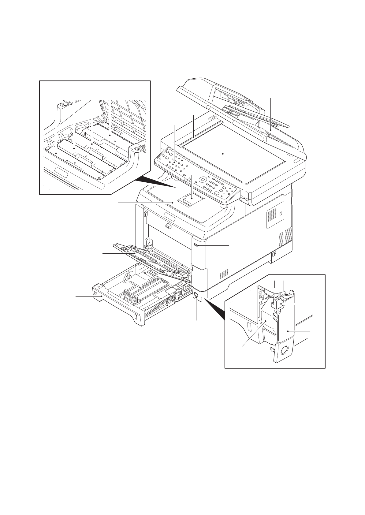
1-1-2 Parts names
1. Document processor (DP)
2. Contact glass
3. Original size Indicator plate
4. Operation panel
5. Top tray lever
6. Paper stopper
7. Top tray
8. MP (Multi-Purpose) tray
9. Cassette
10. USB memory slot
11. Main power switch
12. Toner container K
13. Toner container M
14. Toner container C
15. Toner container Y
16. Waste toner cover
17. Waste toner box
18. Lock release button
(1) Machine (front side)
2KW/2KX
12131415
1
3
4
2
6
5
7
10
8
9
11
Figure 1-1-1
1-1-6
18
16
17
Page 21
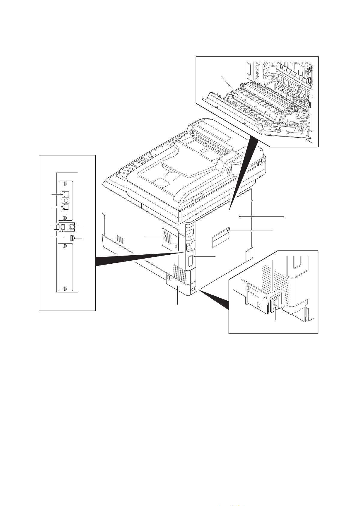
(2) Machine (rear side)
19. Rear cover
20. Rear cover lever
21. IF cover
22. Memory cover
23. Power cord cover
24. Paper conveying unit
25. Power cord connector
26. Network indicators
27. Network interface connector
28. USB interface connector
29. USB memory slot
30. LINE connector*
31. TEL connector*
*: 4 in 1 model (with FAX) only
30
2KW/2KX-2
24
31
26
27
28
29
19
20
22
21
23
25
Figure 1-1-2
1-1-7
Page 22
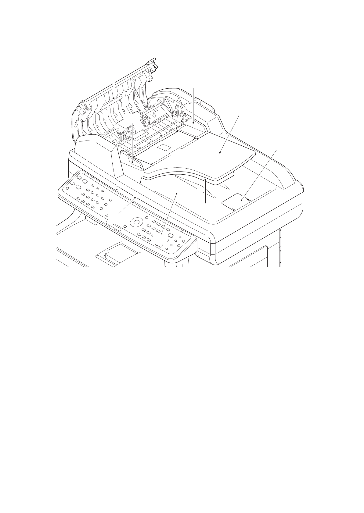
(3) Document processor
32. DP top cover
33. Original width guides
34. Original table
35. Original eject table
36. Switchback table
37. Original stopper
38. Opening Handle
31
2KW/2KX
32
33
32
36
37
35
34
Figure 1-1-3
1-1-8
Page 23
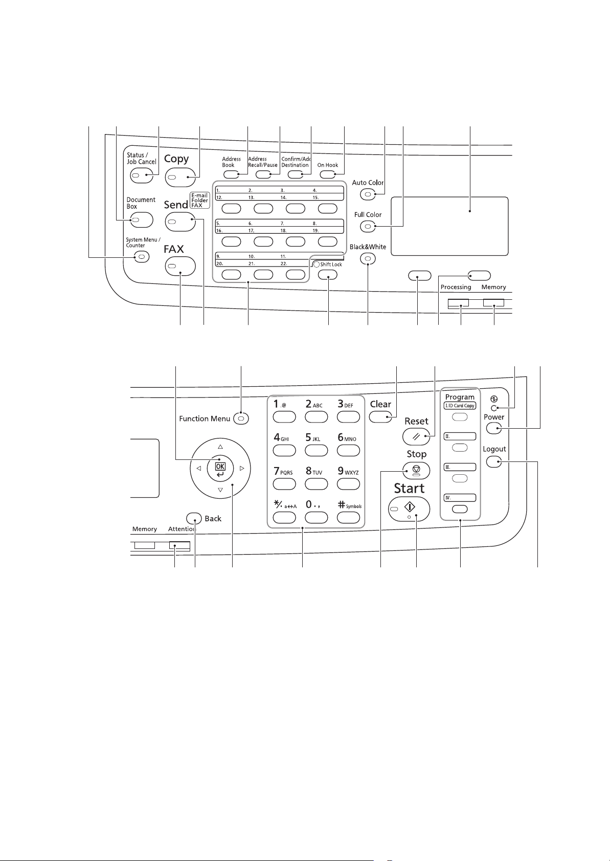
(4) Operation panel
1. System menu/Counter key
2. Document box key
3. Status/Job cancel key
4. Copy key
5. Send key
6. FAX key*
7. Address book key
8. Address recall/Pause key*
9. Confirm/Add destination key
10. On Hook key*
11. One-touch keys
12. Shift Lock key
13. Auto color key
14. Full color key
15. Black and White key
16. Message display
17. Left Select key
18. Right Select key
19. Processing indicator
20. Memory indicator
21. Attention indicator
22. Back key
23. Cursor keys
24. OK key
25. Function Menu key
26. Numeric keys
27. Clear key
28. Reset key
29. Stop key
30. Start key
31. Program keys
32. Main power LED
33. Power key
34. Logout key
*: 4 in 1 model (with FAX) only
2KW/2KX
31 2
24
4 7 8 9 10 16
65
12 18
25
13 14
1511 17
27 32 3328
19 20
20 22 23 26 31 3430
Figure 1-1-4
1-1-9
29
Page 24
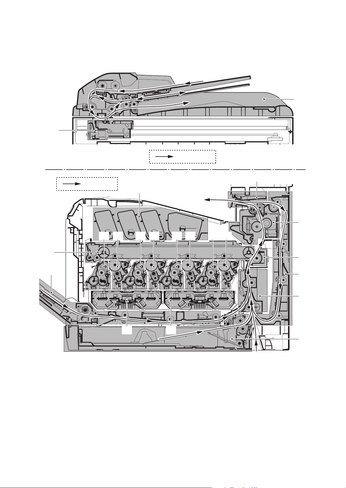
1-1-3 Machine cross section
1. Cassette paper feed section
2. MP tray paper feed section
3. Paper conveying section
4. Laser scanner unit KM
5. Laser scanner unit CY
6. Drum unit K
7. Drum unit M
8. Drum unit C
9. Drum unit Y
10. Developing unit K
11. Developing unit M
12. Developing unit C
13. Developing unit Y
14. Toner container section
15. Primary transfer section
16. Secondary transfer/Separation sections
17. Fuser section
18. Eject/Feed shift sections
19. Duplex section
20. Image scanner unit
21. Document processor
20
2KW/2KX
21
Original path
15
Paper path
14
17
18
13
9
1248 11 7 10 6
16
2
19
3
5
1
Figure 1-1-5
1-1-10
Page 25
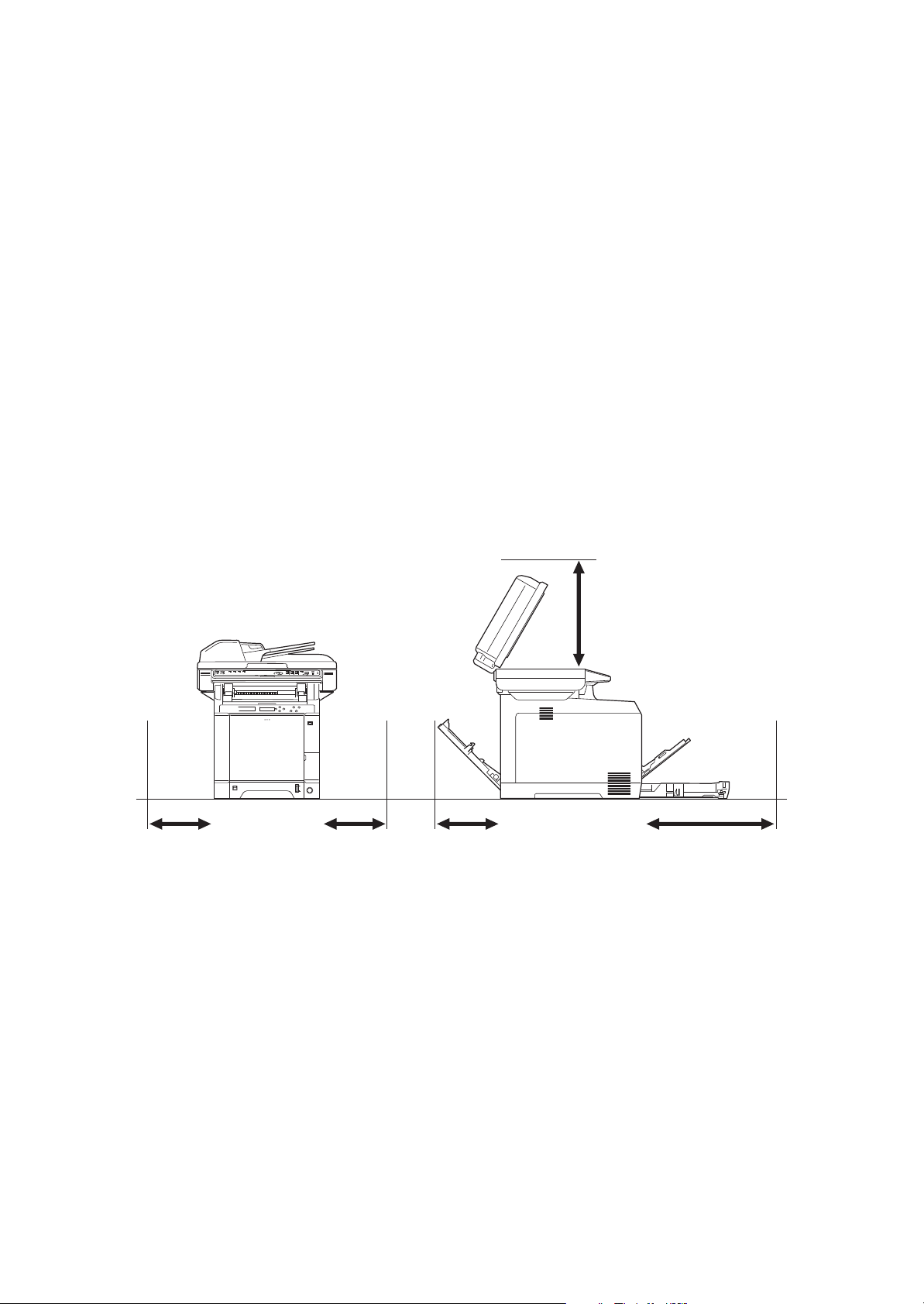
1-2 Installation
1-2-1 Installation environment
1. Temperature: 10 to 32.5°C/50 to 90.5°F
2. Humidity: 15 to 80% RH
3. Power supply: 120 V AC, 8.9 A
220 - 240 V AC, 4.7 A
4. Power source frequency: 50 Hz ±2%/60 Hz ±2%
5. Installation location
Avoid direct sunlight or bright lighting. Ensure that the photoconductor will not be exposed to direct sunlight or other strong light when removing paper jams.
Avoid locations subject to high temperature and high humidity or low temperature and low humidity; an
abrupt change in the environmental temperature; and cool or hot, direct air.
Avoid places subject to dust and vibrations.
Choose a surface capable of supporting the weight of the machine.
Place the machine on a level surface (maximum allowance inclination: 1).
Avoid air-borne substances that may adversely affect the machine or degrade the photoconductor, such
as mercury, acidic of alkaline vapors, inorganic gasses, NOx, SOx gases and chlorine-based organic solvents.
Select a well-ventilated location.
6. Allow sufficient access for proper operation and maintenance of the machine.
2KW/2KX
400 mm
15 3/4"
300 mm300 mm
300 mm
11 13/16"11 13/16"11 13/16"
600 mm
23 5/8"
Figure 1-2-1
1-2-1
Page 26

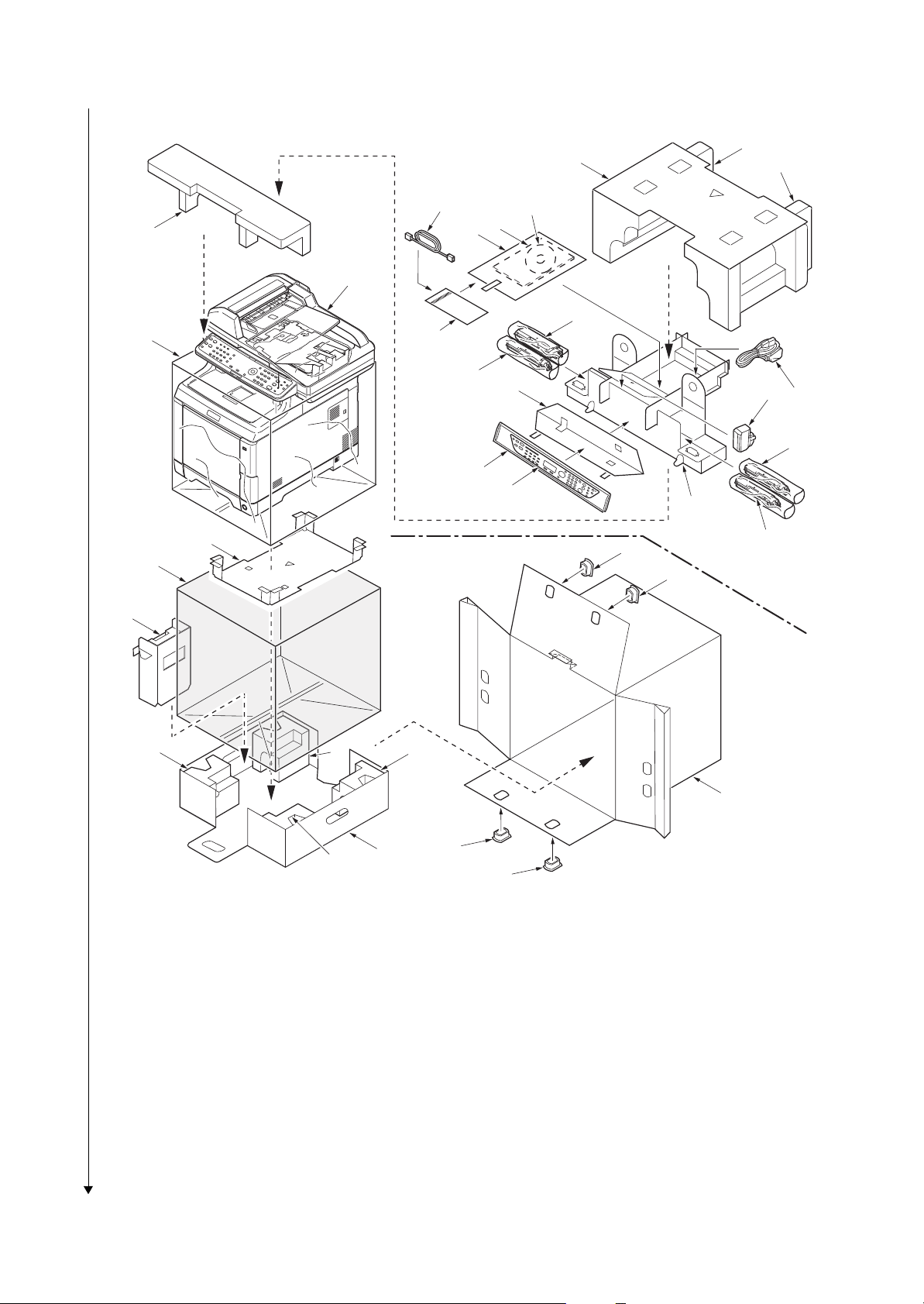
1-2-2 Unpacking
Unpacking
1. Machine
2. Outer case
3. Machine cover (620 × 580)
4. Bottom spacer
5. Plastic bag (650 × 650)
6. Left spacer
7. Bottom pads
8. Bottom case
9. Front pad
10. Top spacer
11. Top pad L
12. Top pad R
13. Plastic bag (240 × 350)
14. Installation guide etc.
15. CD-ROM*
16. Middle spacer
17. Power cord
18. Waste toner box
19. Toner containers
20. Plastic bags (200 × 450)
21. Plastic bag (250 × 600)
22. Operation labels
23. Operation label pad
24. Modular cable**
25. Hinge joints
*: 240 V AC model only.
**: 4 in 1 model (with FAX) only.
220-240 V AC model
2KW/2KX-2
10
11
12
15
9
13
14
1
19
3
24
20
23
17
18
20
21
22
4
5
25
16
19
25
6
7
7
8
Figure 1-2-2
25
1-2-2
2
25
Page 27
120 V AC model
1. Machine
2. Outer case
3. Machine cover (620 × 580)
4. Bottom spacer
5. Plastic bag (650 × 650)
6. Left spacer
7. Bottom pads A
8. Bottom pads B
9. Bottom case
10. Front pad
11. Top spacer
12. Top pad L
13. Top pad R
14. Plastic bag (240 × 350)
15. Installation guide etc.
16. CD-ROM
17. Middle spacer
18. Power cord
19. Waste toner box
20. Toner containers
21. Plastic bags (200 × 450)
22. Plastic bag (250 × 600)
23. Operation labels
24. Operation label pad
25. Modular cable*
26. Plastic bag*
27. Hinge joints
*: 4 in 1 model (with FAX) only.
2KW/2KX-2
10
3
12
25
14
11
16
15
13
1
20
26
21
24
19
18
21
22
23
17
4
27
20
5
27
6
7
8
7
2
9
8
27
27
Figure 1-2-3
Place the machine on a level surface.
1-2-3
Page 28
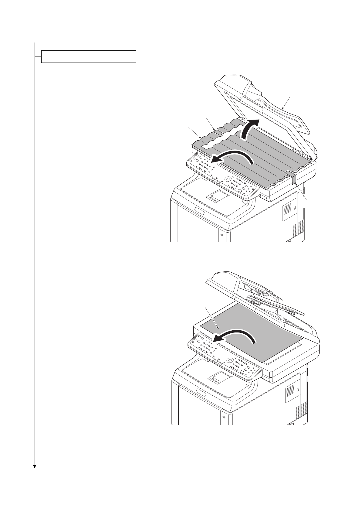
1. Open the DP.
Removing the tapes and pads
2. Remove two tapes.
3. Remove two sheets.
2KW/2KX-2
DP
Ta pe
Sheets
Ta pe
4. Remove the paper.
Figure 1-2-4
Paper
Figure 1-2-5
1-2-4
Page 29
2KW/2KX-4
5. Remove the tape A and pad.
6. Move the lock lever to the position of
release.
* : When turning on power if the lock lever
is not released, the error message is
displayed.
7. Remove the tape B.
8. Close the DP.
Tape A
Pad
Lock lever
DP
Tape B
Figure 1-2-6
9. Remove three tapes.
Ta pe
Ta pe
Ta pe
Figure 1-2-7
1-2-5
Page 30
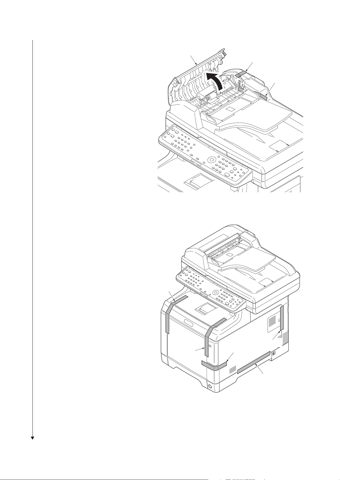
2KW/2KX-2
10. Open the DP top cover.
11. Remove two tapes.
12. Close the DP top cover.
DP top cover
Ta pe
Ta pe
Figure 1-2-8
13. Remove five tapes.
Ta pe
Ta pe
Ta pe
Ta pe
Ta pe
1-2-6
Figure 1-2-9
Page 31

14. Remove four tapes.
2KW/2KX-2
Ta pe
Ta pe
15. Open the top tray.
16. Remove pads A and B.
17. Close the top tray.
Top tray
Ta pe
Figure 1-2-10
Pad B
Ta pe
Pad A
1-2-7
Figure 1-2-11
Page 32

1. Slide the release lever backward.
Installing the toner containers
Toner container
Toner feed slot
2KW/2KX-2
Release lever
2. Facing the toner feed slot up and shake
the toner container 5 to 6 times.
Figure 1-2-12
Figure 1-2-13
1-2-8
Page 33

2KW/2KX-2
Installing the waste toner box
3. Install toner containers (K, M, C, Y).
4. Close the top cover.
To ne r
container M
To ne r
container C
To ne r
container Y
To ne r
container K
Top tray
1. Open the waste toner cover.
2. Open the cap of the waste toner box.
3. Install the waste toner box.
4. Close the waste toner cover.
Figure 1-2-14
Waste toner
cover
Cap
Waste toner box
Figure 1-2-15
1-2-9
Page 34

2KW/2KX-2
Loading paper
1. Pull the cassette out.
2. While pressing the width lever, adjust
the paper width guides to fit the paper
size.
3. While pressing the length lever, adjust
the paper length guide to fit the paper
size.
Paper
length guide
Length lever
Paper width guide
Paper
width guide
Cassette
Width lever
4. Load the paper in the cassette.
5. Turn the paper size dial so that it shows
the paper size you are going to use.
6. Insert the cassette.
Figure 1-2-16
Size dial
Paper
Cassette
Figure 1-2-17
1-2-10
Page 35

1. Connect the interface cable to the
Connecting the interface cable
Connecting the power cord
Completion of the machine installation
machine and PC or network.
2KW/2KX-2
Network interface
USB interface
1. Remove the power cord cover.
2. Connect the power cord to the machine
and the wall outlet.
3. Refit the power cord cover.
4. Press the main power switch to turn
power on.
5. Installing the printer driver (refer to
operation guide).
Figure 1-2-18
Power
source cord
Power cord cover
Figure 1-2-19
1-2-11
Page 36

1-2-3 Installing the expansion memory (option)
Procedure
1. Turn off the main power switch.
Caution: Do not insert or remove
expansion memory while machine
power is on.
Doing so may cause damage to the
machine and the expansion memory.
2. Remove the memory cover.
2KW/2KX-2
Memory cover
3. Release the hook and then open the
fan bracket.
Fan bracket
Figure 1-2-20
2
Hook
1
1-2-12
Figure 1-2-21
Page 37

2KW/2KX-2
4. Insert the expansion memory into the
memory socket so that the notches on
the memory align with the corresponding protrusions in the slot.
5. Close the fan bracket.
6. Refit the memory cover.
7. Print a status page to check the memory expansion (see page 1-3-74).
If memory expansion has been properly
performed, information on the installed
memory is printed with the total memory
capacity has been increased. Standard
memory capacity 768 MB.
Expansion memory
Memory socket
Fan bracket
Figure 1-2-22
1-2-13
Page 38

2KW/2KX
This page is intentionally left blank.
1-2-14
Page 39

2KW/2KX-1
1-3 Maintenance Mode
1-3-1 Maintenance mode
The machine is equipped with a maintenance function which can be used to maintain and service the
machine.
(1) Executing a maintenance item
Start
Enter “10871087” using
the numeric keys.
Enter the maintenance item
number using the cursor left/right keys
or numeric keys.
Press the start key.
The selected maintenance item is run.
Press the stop key.
Yes
Repeat the same
maintenance item?
Maintenance mode is entered.
The maintenance item is selected.
No
Yes
Run another maintenance
item?
No
Turn the main power switch off and on.
End
Maintenance mode is exited and
the system is restarted to initialize it
and to reflect the setting changes.
1-3-1
Page 40

(2) Maintenance modes item list
2KW/2KX-7
Section
General U000 Outputting an own-status report -
Drive,
paper
feed and
paper
conveying
system
Optical U065 Adjust Scanner Motor Speed 0/0
Item
No.
U001 Exit Maintenance Mode -
U002 Setting the factory default data -
U019 Firmware Version -
U034 Adjust Paper Timing Data
LSU Out Top
LSU Out Left
U066 Adjust Table Leading Edge Timing 0/0
U067 Adjust Table Center 0/0
U068 Adjust DP Scan Position 0/0
U070 Adjust DP Motor Speed 0
U071 Adjust DP Leading Edge Timing 0/0/0/0/0
Content of maintenance item
Initial
setting
0/0/0
0/0/0/0/0
U072 Adjust DP Original Center 0/12/0
Operation
panel and
support
equipment
Mode setting U250 Setting the maintenance cycle 200000
Image
processing
U203 Checking DP operation -
U222 Setting the IC card type Other
U251 Checking/clearing the maintenance count 0
U252 Setting the destination -
U253 Switching between double and single counts Double count
U260 Selecting the timing for copy counting Eject
U285 Setting service status page On
U332 Setting the size conversion factor 1.0
U345 Setting the value for maintenance due indication 0
U402 Adjust Print Margin 4.0/4.0/4.0/4.0
U403 Adjust Scanning Margin(Table) 2.0/2.0/2.0/2.0
U404 Adjust Scanning Margin(DP) 3.0/2.5/3.0/4.0
U410 Adjusting the halftone automatically -
U411 Adjusting the scanner automatically -
U425 Setting the target -
1-3-2
Page 41

2KW/2KX-7
Section
Fax U600 Initializing all data -
Item
No.
U601 Initializing permanent data -
U603 Setting user data 1 DTMF
U604 Setting user data 2 2 (120 V)
U605 Clearing data -
U610 Setting system 1
Setting the number of lines to be ignored when receiving a
fax at 100% magnification
Setting the number of lines to be ignored when receiving a
fax in the auto reduction mode
Setting the number of lines to be ignored when receiving a
fax (A4R/LetterR) in the auto reduction mode
U611 Setting system 2
Setting the number of adjustment lines for automatic reduction
Setting the number of adjustment lines for automatic reduction when A4 paper is set
Setting the number of adjustment lines for automatic reduction when letter size paper is set
Content of maintenance item
Initial
setting
1 (220-240 V)
3
0
0
7
22
26
U612 Setting system 3
Selecting if auto reduction in the auxiliary direction is to be
performed
Setting the automatic printing of the protocol list
Setting how trailing edge margins are detected
U620 Setting the remote switching mode One
U625 Setting the transmission system 1
Setting the auto redialing interval
Setting the number of times of auto redialing
U630 Setting communication control 1
Setting the communication starting speed
Setting the reception speed
Setting the waiting period to prevent echo problems at the
sender
Setting the waiting period to prevent echo problems at the
receiver
U631 Setting communication control 2
Setting ECM transmission
Setting ECM reception
Setting the frequency of the CED signal
On
Off
On
3 (120 V)
2 (220-240 V)
2 (120 V)
3 (220-240 V)
14400bps/V17
14400bps
300
75
On
On
2100
U632 Setting communication control 3
Setting the DIS signal to 4 bytes
Setting the CNG detection times in the fax/telephone auto
select mode
1-3-3
Off
2Time
Page 42

2KW/2KX-7
Section
Fax
Item
No.
U633 Setting communication control 4
Enabling/disabling V.34 communication
Setting the number of times of DIS signal reception
Setting the number of times of DIS signal reception
Setting the reference for RTN signal output
U634 Setting communication control 5 0
U640 Setting communication time 1
Setting the one-shot detection time for remote switching
Setting the continuous detection time for remote switching
U641 Setting communication time 2
Setting the T0 time-out time
Setting the T1 time-out time
Setting the T2 time-out time
Setting the Ta time-out time
Setting the Tb1 time-out time
Setting the Tb2 time-out time
Setting the Tc time-out time
Setting the Td time-out time
Content of maintenance item
Initial
setting
On
On
Once
15%
80
56
36
69
30
20
80
60
9 (120 V)
6 (220-240 V)
7
U650 Setting modem 1
Setting the G3 transmission cable equalizer
Setting the G3 reception cable equalizer
Setting the modem detection level
U651 Setting modem 2
Modem output level
DTMF output level (main value)
DTMF output level (level difference)
U660 Setting the NCU
Setting the connection to PBX/PSTN
Setting PSTN dial tone detection
Setting busy tone detection
Setting for a PBX
Setting the loop current detection before dialing
U670 Outputting lists -
U695 FAX function customize On/Off
U699 Setting the software switches -
0dB
0dB
-43dBm
9 (120 V)
10 (220-240 V)
5 (120 V)
10.5 (220-240 V)
2 (120 V)
2.5 (220-240 V)
PSTN
On
On
Loop
On
1-3-4
Page 43

2KW/2KX-7
Section
Others U910 Clearing the print coverage data -
Item
No.
U917 Setting backup data reading/writing -
U920
U927 Clearing the all copy counts and machine life counts (one
U928 Checking machine life counts -
U977 Data capture mode -
U995 Memory data Individual setting -
Checking the copy counts -
time only)
Content of maintenance item
Initial
setting
-
1-3-5
Page 44

(3) Contents of the maintenance mode items
Display Output list
Maintenance List of the current settings of the maintenance modes
Event Outputs the event log
All Outputs the all reports
Display Output list
Print Outputs the report
USB (Text) Sends output data to the USB memory (text type)
USB (HTML) Sends output data to the USB memory (HTML type)
Item No. Description
U000 Outputting an own-status report
Description
Outputs lists of the current settings of the maintenance items and paper jam and service call
occurrences. Outputs the event log. Also sends output data to the USB memory.
Purpose
To check the current setting of the maintenance items, or paper jam or service call occurrences.
Before initializing or replacing the backup RAM, output a list of the current settings of the maintenance items to reenter the settings after initialization or replacement.
Method
1. Press the start key.
2. Select the item to be output using the cursor up/down keys.
2KW/2KX
3. Press the start key. A list is output.
Method: Send to the USB memory
1. Press the power key on the operation panel, and after verifying the main power indicator has
gone off, switch off the main power switch.
2. Insert USB memory in USB memory slot.
3. Turn the main power switch on.
4. Enter the maintenance item.
5. Press the start key.
6. Select the item to be send.
7. Select [Text] or [HTML].
8. Press the start key.
Output will be sent to the USB memory.
Completion
Press the stop key. The screen for selecting a maintenance item No. is displayed.
1-3-6
Page 45

Item No. Description
U000 Event log
Event Log
MFP
(1)
Firmware version 2KX_2000.000.000 2010.04.06
2KW/2KX-2
(2)
06/Apr/2010 08:40
(3) (4) (5)
[XXXXXXXX] [XXXXXXXX] [XXXXXXXX]
(7)
Paper Jam Log
#
16
15
14
13
12
11
10
9
8
7
6
5
4
3
2
1
Count.
1876543
166554
4988
4988
4988
4988
110 3
110 3
110 3
110 3
1027
1027
1027
1027
406
36
Event Descriprions
0501.01.08.01.01
4020.01.08.01.01
0501.01.08.01.01
4020.01.08.01.01
0501.01.08.01.01
4020.01.08.01.01
0501.01.08.01.01
4020.01.08.01.01
0501.01.08.01.01
4020.01.08.01.01
0501.01.08.01.01
4020.01.08.01.01
0501.01.08.01.01
4020.01.08.01.01
0501.01.08.01.01
4020.01.08.01.01
0501.01.08.01.01
(a) (b) (c) (d) (e)
(11)
Counter Log
J0100:
(f) (g) (h)
J0105:
J0106:
J0110:
J0 111:
.
.
.
.
.
.
J0512:
0
J0513:
0
J0518:
0
J0519:
0
J1020:
0
.
.
.
.
.
.
J4201:
J4202:
J4203:
J4208:
J4209:
.
.
.
.
.
.
0
0
0
0
0
0
0
0
0
0
C0030:
C0070:
C0100:
C0120:
C0130:
.
.
.
.
.
.
(8)
Service Call Log
#
Count.
8
1881214
7
178944
6
5296
5
5295
4
2099
3
1054
2
809
1
30
Maintenance Log
(9)
#
Count.
8
1045571
7
104511
6
7045
5
3454
4
3454
3
3454
2
417
1
34
Unknown toner Log
(10)
#
Count.
5
3454
4
3454
3
3454
2
406
1
32
C2100:
1
C2200:
1
C2300:
1
C2330:
1
C2340:
1
.
.
.
.
.
.
1
1
1
1
1
Service Code
01.6000
01.2100
01.4000
01.6000
01.2100
01.4000
01.6000
01.2100
Item
01.00
01.00
01.00
01.00
01.01
01.01
01.01
01.01
Item
01.00
01.00
01.00
01.00
01.00
1
T00:
1
T01:
Figure 1-3-1
1-3-7
(6)
[XXXXXXXXXXXXXXXX]
Page 46

Item No. Description
No. Items Description
(1) System version
(2) System date
(3) Engine soft version
(4) Engine boot version
(5) Operation panel mask version
(6) Machine serial number
(7) Paper Jam
Log
# Count. Event
Remembers 1 to 16 of
occurrence. If the occurrence of the previous
paper jam is less than
16, all of the paper jams
are logged. When the
occurrence excesseds
16, the oldest occurrence is removed.
The total page count
at the time of the
paper jam.
Log code (hexadecimal, 5 categories)
(a) Cause of a paper
jam
(b) Paper source
(c) Paper size
(d) Paper type
(e) Paper eject
(a) Cause of paper jam (Hexadecimal)
Refer to P.1-4-1 for paper jam location
0100: Controller sequence error
0105: Registration sensor not detected
0106: Controller sequence error
0110: Top tray open
0111: Rear cover open
0112: Front cover open
0113: MP tray open
0120: Controller sequence error
0121: Controller sequence error
0211: Rear cover open (paper feeder 1)
0212: Rear cover open (paper feeder 2)
0501: No paper feed from cassette 1
0502: No paper feed from cassette 2
0503: No paper feed from cassette 3
0508: No paper feed from duplex section
0509: No paper feed from MP tray
0511: Multiple sheets in cassette 1
0512: Multiple sheets in cassette 2
0513: Multiple sheets in cassette 3
0518: Multiple sheets in duplex section
0519: Multiple sheets in MP tray
1020: MP paper conveying sensor is turned ON
1403: PF feed sensor 1 does not turn ON
1413: PF feed sensor 1 does not turn OFF
1420: PF feed sensor 1 is turned ON
1620: PF feed sensor 2 is turned ON
U000 Detail of event log
2KW/2KX-3
1-3-8
Page 47

Item No. Description
No. Items Description
(7)
cont.
Paper Jam
Log
4002: Registration sensor does not turn ON (Paper feeder 1)
4003: Registration sensor does not turn ON (Paper feeder 2)
4009: Registration sensor does not turn ON (MP tray)
4012: Registration sensor does not turn OFF (Paper feeder 1)
4013: Registration sensor does not turn OFF (Paper feeder 2)
4019: Registration sensor does not turn OFF (MP tray)
4020: Registration sensor is turned ON
4201: Eject sensor does not turn ON (Cassette)
4202: Eject sensor does not turn ON (Paper feeder 1)
4203: Eject sensor does not turn ON (Paper feeder 2)
4208: Eject sensor does not turn ON (Duplex)
4209: Eject sensor does not turn ON (MP tray)
4211: Eject sensor does not turn OFF (Cassette)
4212: Eject sensor does not turn OFF (Paper feeder 1)
4213: Eject sensor does not turn OFF (Paper feeder 2)
4218: Eject sensor does not turn OFF (Duplex)
4219: Eject sensor does not turn OFF (MP tray)
4220: Eject sensor is turned ON
9010: DP top cover open
9400: No original feed
9401: An original jam in the original switchback section 2
9410: An original jam in the original conveying section
9411: An original jam in the original switchback section 1
(b) Detail of paper source (Hexadecimal)
00: MP tray
01: Cassette 1
02: Cassette 2 (paper feeder 1)
03: Cassette 3 (paper feeder 2)
04 to 09: Reserved
(c) Detail of paper size (Hexadecimal)
00: (Not specified)
01: Monarch
02: Business
03: International DL
04: International C5
05: Executive
06: Letter-R
86: Letter-E
07: Legal
08: A4R
88: A4E
09: B5R
89: B5E
0A: A3
0B: B4
0C: Ledger
0D: A5R
0E: A6
0F: B6
10: Commercial #9
11: Commercial #6
12: ISO B5
13: Custom size
1E: C4
1F: Postcard
20: Reply-paid post-
card
21: Oficio II
22: Special 1
23: Special 2
24: A3 wide
25: Ledger wide
26: Full bleed paper
(12 x 8)
27: 8K
28: 16K-R
A8: 16K-E
32: Statement-R
B2: Statement-E
33: Folio
34: Western type 2
35: Western type 4
U000
2KW/2KX
1-3-9
Page 48

Item No. Description
No. Items Description
(7)
cont.
Paper Jam
Log
(d) Detail of paper type (Hexadecimal)
01: Plain
02: Transparency
03: Preprinted
04: Labels
05: Bond
06: Recycled
07: Vellum
08: Rough
09: Letterhead
0A: Color
0B: Prepunched
0C: Envelope
0D: Cardstock
0E: Coated
0F: 2nd side
10: Thick
11: High quality
15: Custom 1
16: Custom 2
17: Custom 3
18: Custom 4
19: Custom 5
1A: Custom 6
1B: Custom 7
1C: Custom 8
(e) Detail of paper eject location (Hexadecimal)
01: Face down (FD)
(8) Service Call
Log
# Count. Service Code
Remembers 1 to 8
of occurrence of self
diagnostics error. If
the occurrence of
the previous diagnostics error is less
than 8, all of the
diagnostics errors
are logged.
The total page
count at the time of
the self diagnostics
error.
Self diagnostic error code
(See page 1-4-7)
Example:
01.6000
01: Self diagnostic error
6000: Self diagnostic error
code number
(9) Maintenance
Log
# Count. Item
Remembers 1 to 8
of occurrence of
replacement. If the
occurrence of the
previous replacement of toner container is less than 8,
all of the occurrences of replacement are logged.
The total page
count at the time of
the replacement of
the toner container.
Code of maintenance
replacing item
(1 byte, 2 categories)
First byte (Replacing item)
01: Toner container
Second byte
(Type of replacing item)
00: Black
01: Cyan
02: Magenta
03: Yellow
First byte (Replacing item)
02: Maintenance kit
Second byte
(Type of replacing item)
01: MK-590/592/594
U000
2KW/2KX-5
1-3-10
Page 49

Item No. Description
No. Items Description
(10) Unknown Toner
Log
# Count. Item
Remembers 1 to 5
of occurrence of
unknown toner
detection. If the
occurrence of the
previous unknown
toner detection is
less than 5, all of
the unknown toner
detection are
logged.
The total page count
at the time of the
toner empty error
with using an
unknown toner container.
Unknown toner log
code
(1 byte, 2 categories)
First byte
01: Toner container
(Fixed)
Second byte
00: Black
01: Cyan
02: Magenta
03: Yellow
(11) Counter Log
Comprised of
three log counters including
paper jams, self
diagnostics
errors, and
replacement of
the toner container.
(f) Paper jam (g) Self diagnostic
error
(h) Maintenance item
replacing
Indicates the log
counter of paper
jams depending on
location.
Refer to Paper Jam
Log.
All instances including those are not
occurred are displayed.
Indicates the log
counter of self diagnostics errors
depending on
cause.
(See page 1-4-7)
Example:
C6000: 4
Self diagnostics
error 6000 has happened four times.
Indicates the log counter depending on the
maintenance item for
maintenance.
T: Toner container
00: Black
01: Cyan
02: Magenta
03: Yellow
M: Maintenance kit
01: MK-590/592/594
Example:
T00: 1
The toner container has
been replaced once.
U000
2KW/2KX-2
1-3-11
Page 50

Item No. Description
Codes Description
0001 Controller error
0020 Engine error
0040 Scanner error
U001 Exit Maintenance Mode
Description
Exits the maintenance mode and returns to the normal copy mode.
Purpose
To exit the maintenance mode.
Method
1. Press the start key. The normal copy mode is entered.
U002 Setting the factory default data
Description
Restores the machine conditions to the factory default settings.
Purpose
To move the image scanner unit to the home position.
2KW/2KX-7
Method
1. Press the start key.
2. Select [Mode1(All)] using the cursor up/down keys.
3. Press the start key.
The imege scanner unit returns to the home position.
4. Turn the main power switch off and on.
* : An error code is displayed in case of an initialization error.
When errors occurred, turn main power switch off then on, and execute initialization using
maintenance item U002.
Error codes
1-3-12
Page 51

Item No. Description
Display Description
Main Main ROM
MMI Operation ROM
Engine Engine ROM
Engine Boot Engine booting
Scanner Scanner ROM
Scanner Boot Scanner booting
Option Language Optional language ROM
Color Table Color table ROM
Cassette2 Paper feeder 2
Cassette3 Paper feeder 3
Fax Boot Fax Boot
Fax APL Fax APL
Fax IPL Fax IPL
U019 Firmware Version
Description
Displays the part number of the ROM fitted to each PWB.
Purpose
To check the part number or to decide, if the newest version of ROM is installed.
Method
1. Press the start key. The ROM version are displayed.
2. Change the screen using the cursor up/down keys.
2KW/2KX-7
Completion
Press the stop key. The screen for selecting a maintenance item No. is displayed.
1-3-13
Page 52

Item No. Description
Display Description
LSU Out Top Leading edge registration adjustment
LSU Out Left Center line adjustment
Display Description
Setting
range
Initial
setting
Change in
value per step
MPT Paper feed from MP tray -100 to 600 0 0.1 mm
Cassette Paper feed from cassette -100 to 600 0 0.1 mm
Duplex Duplex mode (second) -100 to 600 0 0.1 mm
U034 Adjust Paper Timing Data
Description
Adjusts the leading edge registration or center line.
Purpose
Make the adjustment if there is a regular error between the leading edges of the copy image and
original.
Make the adjustment if there is a regular error between the center lines of the copy image and
original.
Method
1. Press the start key.
2. Select the item to be adjusted.
2KW/2KX-7
Adjustment: [LSU Out Top]
1. Press the system menu key.
2. Press the start key to output a test pattern.
3. Press the system menu key.
4. Select the item to be adjusted.
5. Change the setting value using the cursor left/rigrt keys or numeric keys.
For output example 1, increase the value. For output example 2, decrease the value.
Leading edge
registration
(20 ± 1.0 mm)
Correct image
Output
example 1
Figure 1-3-2
6. Press the start key. The value is set.
1-3-14
Output
example 2
Page 53

Item No. Description
U034
U066
(P.1-3-18)
U071
(P.1-3-22)
Display Description
Setting
range
Initial
setting
Change in
value per step
MPT Paper feed from MP tray -100 to 600 0 0.1 mm
Cassette1 Paper feed from optional cassette1 -100 to 600 0 0.1 mm
Cassette2 Paper feed from optional cassette2 -100 to 600 0 0.1 mm
Cassette3 Paper feed from optional cassette3 -100 to 600 0 0.1 mm
Duplex Duplex mode (second) -100 to 600 0 0.1 mm
U034
U067
(P.1-3-19)
U072
(P.1-3-24)
U034 Caution
Check the copy image after the adjustment. If the image is still incorrect, perform the following
adjustments in maintenance mode.
Adjustment: [LSU Out Left]
1. Press the system menu key.
2. Press the start key to output a test pattern.
3. Press the system menu key.
4. Select the item to be adjusted.
2KW/2KX-7
5. Change the setting value using the cursor left/rigrt keys or numeric keys.
For output example 1, increase the value. For output example 2, decrease the value.
Center line of printing
(within ± 2.0 mm)
Correct image
Output
example 1
Output
example 2
Figure 1-3-3
6. Press the start key. The value is set.
Caution
Check the copy image after the adjustment. If the image is still incorrect, perform the following
adjustments in maintenance mode.
Completion
Press the stop key. The screen for selecting a maintenance item No. is displayed.
1-3-15
Page 54

Item No. Description
Display Description
Setting
range
Initial
setting
Change in
value per step
Y Scan Zoom
Scanner magnification in the
main scanning direction
-32 to 127 0 0.1 %
X Scan Zoom
Scanner magnification in the
auxiliary scanning direction
-25 to 25 0 0.1 %
U065 Adjust Scanner Motor Speed
Description
Adjusts the magnification of the original scanning.
Purpose
Make the adjustment if the magnification in the main scanning direction is incorrect.
Make the adjustment if the magnification in the auxiliary scanning direction is incorrect.
Method
1. Press the start key.
2. Press the system menu key.
3. Place an original and press the start key to make a test copy.
4. Press the system menu key.
5. Select the item to be adjusted.
2KW/2KX-7
Adjustment: [Y Scan Zoom]
1. Change the setting value using the cursor left/rigrt keys or numeric keys.
For copy example 1, increase the value. For copy example 2, decrease the value.
Increasing the setting enlarges the image and decreasing it narrows the image.
Original Copy
example 1
Copy
example 2
Figure 1-3-4
2. Press the start key. The value is set.
1-3-16
Page 55

Item No. Description
U065 Adjustment: [X Scan Zoom]
1. Change the setting value using the left/rigrt keys or numeric keys.
For copy example 1, increase the value. For copy example 2, decrease the value.
Increasing the value makes the image longer, while decreasing the value makes the image
shorter.
2KW/2KX-7
Original Copy
example 1
Copy
example 2
Figure 1-3-5
2. Press the start key. The value is set.
Completion
Press the stop key. The screen for selecting a maintenance item No. is displayed.
1-3-17
Page 56

Item No. Description
Display Description
Setting
range
Initial
setting
Change in
value per step
Front Scanner leading edge registra-
tion
-45 to 45 0 0.086 mm
Rotate Scanner leading edge registra-
tion (rotate copying)
-45 to 45 0 0.086 mm
U034
(P.1-3-14)
U065
(P.1-3-16)
U066
U066 Adjust Table Leading Edge Timing
Description
Adjusts the scanner leading edge registration of the original scanning.
Purpose
Make the adjustment if there is a regular error between the leading edges of the copy image and
original.
Adjustment
1. Press the start key.
2. Press the system menu key.
3. Place an original and press the start key to make a test copy.
4. Press the system menu key.
5. Select the item to be adjusted.
2KW/2KX-7
6. Change the setting value using the cursor left/right keys or numeric keys.
For copy example 1, increase the value. For copy example 2, decrease the value.
Increasing the value moves the image forward and decreasing the value moves the image
backward.
Leading edge registration of the copy image (+1.0/-1.5 mm or less)
Original
Copy
example 1
Copy
example 2
Figure 1-3-6
7. Press the start key. The value is set.
Caution
If the above adjustment does not optimize the leading edge registration, proceed with the following maintenance modes.
Completion
Press the stop key. The screen for selecting a maintenance item No. is displayed.
1-3-18
Page 57

Item No. Description
Display Description
Setting
range
Initial
setting
Change in
value per step
Front Scanner center line -40 to 40 0 0.085 mm
Rotate Scanner center line (rotate
copying)
-40 to 40 0 0.085 mm
U034
(P.1-3-14)
U065
(P.1-3-16)
U067
U067 Adjust Table Center
Description
Adjusts the scanner center line of the original scanning.
Purpose
Make the adjustment if there is a regular error between the center lines of the copy image and
original.
Adjustment
1. Press the start key.
2. Press the system menu key.
3. Place an original and press the start key to make a test copy.
4. Press the system menu key.
5. Select the item to be adjusted.
2KW/2KX-7
6. Change the setting value using the cursor left/right keys or numeric keys.
For copy example 1, decrease the value. For copy example 2, increase the value.
Increasing the value moves the image leftward and decreasing it moves the image rightward.
Center line of the copy image (within ± 2.0 mm)
Original Copy
example 1
Copy
example 2
Figure 1-3-7
7. Press the start key. The value is set.
Caution
If the above adjustment does not optimize the center line, proceed with the following maintenance modes.
Completion
Press the stop key. The screen for selecting a maintenance item No. is displayed.
1-3-19
Page 58

Item No. Description
Display Description
Setting
range
Initial
setting
Change in
value per step
DP Read Starting position adjustment for
scanning originals
-33 to 33 0 0.086 mm
Black Line Scanning position for the test
copy originals
0 to 3 0 0.22 mm
U068 Adjust DP Scan Position
Description
Adjusts the position for scanning originals from the DP. Performs the test copy at the four scanning positions after adjusting.
Purpose
Used when the image fogging occurs because the scanning position is not proper when the DP is
used. Run U071 to adjust the timing of DP leading edge when the scanning position is changed.
Setting
1. Press the start key.l
2KW/2KX-7
2. Select [DP Read].
3. Change the setting using the cursor left/right keys or numeric keys.
When the setting value is increased, the scanning position moves to the right and it moves to
the left when the setting value is decreased.
4. Press the start key. The value is set.
5. Select [Black Line].
6. Change the setting using the +/- keys or numeric keys.
7. Press the start key. The value is set.
8. Set the original (the one which density is known) in the DP and press the system menu key.
9. Press the start key. Test copy is executed.
10. Perform the test copy at each scanning position with the setting value from 0 to 3 and check
that no black line appears and the image is normally scanned.
Completion
Press the stop key. The screen for selecting a maintenance item No. is displayed.
1-3-20
Page 59

Item No. Description
Display Description
Setting
range
Initial
setting
Change in
value per step
Convey
Speed
Magnification in the auxiliary
scanning direction of CCD
(first side)
-25 to 25 0 0.1 %
U070 Adjust DP Motor Speed
Description
Adjusts the DP original scanning speed.
Purpose
Make the adjustment if the magnification is incorrect in the auxiliary scanning direction when the
DP is used.
Adjustment
1. Press the start key.
2. Press the system menu key.
3. Place an original on the DP and press the start key to make a test copy.
4. Press the system menu key.
5. Select [Convey Speed].
2KW/2KX-7
6. Change the setting value using the cursor left/right keys or numeric keys.
For copy example 1, increase the value. For copy example 2, decrease the value.
Increasing the value makes the image longer, while decreasing the value makes the image
shorter.
Original Copy
example 1
Copy
example 2
Figure 1-3-8
7. Press the start key. The value is set.
Completion
Press the stop key. The screen for selecting a maintenance item No. is displayed.
1-3-21
Page 60

Item No. Description
Display Description
Setting
range
Initial
setting
Change in
value per step
Front Head Leading edge registration of
CCD (first side)
-32 to 32 0 0.196 mm
Front Tail Trailing edge registration of
CCD (first side)
-32 to 32 0 0.196 mm
Back Head Leading edge registration of
CCD (second side)
-45 to 45 0 0.196 mm
Back Tail Trailing edge registration of
CCD (second side)
-45 to 45 0 0.196 mm
Rotate Leading edge registration
(rotate copying)
-128 to 127 0 0.196 mm
U071 Adjust DP Leading Edge Timing
Description
Adjusts the DP original scanning timing.
Purpose
Make the adjustment if there is a regular error between the leading or trailing edges of the original and the copy image when the DP is used.
Method
1. Press the start key.
2. Press the system menu key.
3. Place an original on the DP and press the start key to make a test copy.
4. Press the system menu key.
5. Select the item to be adjusted.l
2KW/2KX-7
1-3-22
Page 61

Item No. Description
U034
(P.1-3-14)
U071
U071 Adjustment: Leading edge registration
1. Change the setting value using the cursor left/right keys or numeric keys.
For copy example 1, increase the value. For copy example 2, decrease the value.
Increasing the value moves the image forward and decreasing the value moves the image
backward.
2KW/2KX-7
Original Copy
example 1
Copy
example 2
Figure 1-3-9
2. Press the start key. The value is set.
Caution
If the first side is adjusted, check the second side and if adjustment is required, carry out the
adjustment.
If the above adjustment does not optimize the leading edge registration, proceed with the following maintenance modes.
Adjustment: Trailing edge registration
1. Change the setting value using the cursor left/right keys or numeric keys.
For copy example 1, increase the value. For copy example 2, decrease the value.
Original
Copy
example 1
Copy
example 2
Figure 1-3-10
2. Press the start key. The value is set.
Caution
If the first side is adjusted, check the second side and if adjustment is required, carry out the
adjustment.
Completion
Press the stop key. The screen for selecting a maintenance item No. is displayed.
1-3-23
Page 62

Item No. Description
Display Description
Setting
range
Initial
setting
Change in
value per step
Front DP center line (first side) -39 to 39 0 0.085 mm
Back DP center line (second side) -39 to 39 12 0.085 mm
Rotate DP center line (rotate copying) -39 to 39 0 0.085 mm
U034
(P.1-3-14)
U065
(P.1-3-16)
U067
(P.1-3-19)
U072
U072 Adjust DP Original Center
Description
Adjusts the scanning start position for the DP original.
Purpose
Make the adjustment if there is a regular error between the centers of the original and the copy
image when the DP is used.
Adjustment
1. Press the start key.
2. Press the system menu key.
3. Place an original on the DP and press the start key to make a test copy.
4. Press the system menu key.
5. Select the item to be adjusted.l
2KW/2KX-7
6. Change the setting value using the cursor left/right keys or numeric keys.
For copy example 1, increase the value. For copy example 2, decrease the value.
Increasing the value moves the image rightward and decreasing it moves the image leftward.
Original Copy
example 1
Copy
example 2
Figure 1-3-11
7. Press the start key. The value is set.
Caution
If the first side is adjusted, check the second side and if adjustment is required, carry out the
adjustment.
If the above adjustment does not optimize the center line, proceed with the following maintenance modes.
Completion
Press the stop key. The screen for selecting a maintenance item No. is displayed.
1-3-24
Page 63

Item No. Description
Display Description
Normal Speed Normal reading (600 dpi)
High Speed High-speed reading
Display Description
CCD ADP (Non-P) Without paper, single-sided original of CCD
(continuous operation)
CCD ADP With paper, single-sided original of CCD
CCD RADP (Non-P) Without paper, double-sided original of CCD
(continuous operation)
CCD RADP With paper, double-sided original of CCD
U203 Checking DP operation
Description
Simulates the original conveying operation separately in the DP.
Purpose
To check the DP operation.
Method
1. Press the start key.
2. Place an original in the DP if running this simulation with paper.
3. Select the speed to be operated using the cursor up/down keys.
4. Press the start key.
5. Select the item to be operated using the cursor up/down keys.
2KW/2KX
6. Press the start key. The operation starts.
7. To stop continuous operation, press the stop key.
Completion
Press the stop key. The screen for selecting a maintenance item No. is displayed.
1-3-25
Page 64

Item No. Description
Display Description
Other The type of IC card is SSFC.
SSFC The type of IC card is not SSFC.
Description Setting range Initial setting
Maintenance cycle 0 to 9999999 200000
U222 Setting the IC card type
Description
Sets the type of IC card.
Purpose
To change the type of IC card.
Setting
1. Press the start key.
2. Select the item using the cursor up/down keys.
* : Initial setting: Other
3. Press the start key. The setting is set.
Completion
Press the stop key. The screen for selecting a maintenance item No. is displayed.
2KW/2KX-2
U250 Setting the maintenance cycle
Description
Displays, clears and changes the maintenance cycle.
Purpose
To check and change the maintenance cycle.
Method
1. Press the start key. The currently set maintenance cycle is displayed.
Setting
1. Select [M.Cnt A] using the cursor up/down keys.
2. Change the setting using the cursor left/right keys or numeric keys.
3. Press the start key. The value is set.
Clearing
1. Select [Clear] using the cursor up/down keys.
2. Press the start key. The count is cleared.
Completion
Press the stop key. The screen for selecting a maintenance item No. is displayed.
1-3-26
Page 65

Item No. Description
Description Setting range Initial setting
Maintenance count 0 to 9999999 0
U251 Checking/clearing the maintenance count
Description
Displays, clears and changes the maintenance count.
Purpose
To check the maintenance count.
Also to clear the count during maintenance service (replacing the maintenance kit).
Method
1. Press the start key. The maintenance count is displayed.
Setting
1. Select [M.Cnt A] using the cursor up/down keys.
2. Change the setting using the cursor left/right keys or numeric keys.
3. Press the start key. The count is set.
2KW/2KX
Clearing
1. Select [Clear] using the cursor up/down keys.
2. Press the start key. The count is cleared.
Completion
Press the stop key. The screen for selecting a maintenance item No. is displayed.
1-3-27
Page 66

Item No. Description
Display Description
Inch Inch (North America) specifications
Europe Metric Metric (Europe) specifications
Asia Pacific Metric (Asia Pacific) specifications
Australia Australia specifications
China China specifications
Korea Korea specifications
U252 Setting the destination
Description
Switches the operations and screens of the machine according to the destination.
Purpose
To be executed after initializing the backup RAM, in order to return the setting to the value before
replacement or initialization.
Setting
1. Press the start key.
2. Select the destination using the cursor up/down keys.
2KW/2KX-4
3. Press the start key.
4. Turn the main power switch off and on.
Supplement
The specified initial settings are provided according to the destinations in the maintenance items
below. To change the initial settings in those items, be sure to run maintenance item U021 after
changing the destination.
1-3-28
Page 67

Item No. Description
Display Description
Color Count system of color mode
B/W Count system of black/white mode
Display Description
SGL Count(All) Single count for all size paper
DBL Count(Folio) Double count for Folio size or larger
Display Description
Feed When secondary paper feed starts
Eject When the paper is ejected
U253 Switching between double and single counts
Description
Switches the count system for the total counter and other counters.
Purpose
Used to select, according to the preference of the user (copy service provider), if folio size paper
is to be counted as one sheet (single count) or two sheets (double count).
Setting
1. Press the start key.
2. Select the item using the cursor up/down keys.
3. Press the start key.
4. Select the count system using the cursor up/down keys.
2KW/2KX-2
* : Initial setting: DBL Count(Folio)
5. Press the start key. The setting is set.
Completion
Press the stop key. The screen for selecting a maintenance item No. is displayed.
U260 Selecting the timing for copy counting
Description
Changes the copy count timing for the total counter and other counters.
Purpose
To be set according to user request.
Setting
1. Press the start key.
2. Select the copy count timing using the cursor up/down keys.
* : Initial setting:
Eject
3. Press the start key. The setting is set.
Completion
Press the stop key. The screen for selecting a maintenance item No. is displayed.
1-3-29
Page 68

Item No. Description
Display Description
On Displays the print coverage
Off Not to display the print coverage
Display Description Setting range Initial setting
Rate Size parameter 0.1 to 3.0 1.0
U285 Setting service status page
Description
Determines displaying the print coverage report on reporting.
Purpose
According to user request, changes the setting.
Setting
1. Press the start key.
2. Select On or Off using the cursor up/down keys.
* : Initial setting: On
3. Press the start key. The setting is set.
Completion
Press the stop key. The screen for selecting a maintenance item No. is displayed.
2KW/2KX
U332 Setting the size conversion factor
Description
Sets the coefficient of nonstandard sizes in relation to the A4/Letter size. The coefficient set here
is used to convert the black ratio in relation to the A4/Letter size and to display the result in user
simulation.
Purpose
To set the coefficient for converting the black ratio for nonstandard sizes in relation to the A4/Letter size.
Setting
1. Press the start key.
2. Change the setting using the cursor left/right keys or numeric keys.
3. Press the start key. The value is set.
Completion
Press the stop key. The screen for selecting a maintenance item No. is displayed.
1-3-30
Page 69

Item No. Description
Description Setting range Initial setting
Time for maintenance due indication
(Remaining number of copies that can be made
before the current maintenance cycle ends)
0 to 9999 0
U345 Setting the value for maintenance due indication
Description
Sets when to display a message notifying that the time for maintenance is about to be reached,
by setting the number of copies that can be made before the current maintenance cycle ends.
When the difference between the number of copies of the maintenance cycle and that of the
maintenance count reaches the set value, the message is displayed.
Purpose
To change the time for maintenance due indication.
Setting
1. Press the start key.
2. Select [Cnt] using the cursor up/down keys.
3. Change the setting using the cursor left/right keys.
4. Press the start key. The value is set.
2KW/2KX-1
Clearing
1. Select [Clear] using the cursor up/down keys.
2. Press the start key. The value is cleared.
Completion
Press the stop key. The screen for selecting a maintenance item No. is displayed.
1-3-31
Page 70

Item No. Description
Display Description
Setting
range
Initial
setting
Change in
value per step
Lead Printer leading edge margin 0 to 100 40 0.1mm
A Margin Printer left margin 0 to 100 40 0.1mm
C Margin Printer right margin 0 to 100 40 0.1mm
Trail Printer trailing edge margin 0 to 100 40 0.1mm
U034
(P.1-3-14)
U402
U402 Adjust Print Margin
Description
Adjusts margins for image printing.
Purpose
Make the adjustment if margins are incorrect.
Adjustment
1. Press the start key.
2. Press the system menu key.
3. Press the start key to output a test pattern.
4. Press the system menu key.
5. Select the item to be adjusted.
2KW/2KX-7
6. Change the setting value using the cursol left/right keys or numeric keys.
Increasing the value makes the margin wider, and decreasing it makes the margin narrower.
Printer leading edge margin
(4.0 +1.5/-1.0 mm)
Printer
left margin
(2.5 +1.5/-2.0 mm)
Printer trailing edge margin
(4.0 mm or less)
Printer
right margin
(2.5 +1.5/-2.0 mm)
Figure 1-3-12
7. Press the start key. The value is set.
Caution
If the above adjustment does not optimize the margins, perform the following maintenance
modes.
Completion
Press the stop key. The screen for selecting a maintenance item No. is displayed.
1-3-32
Page 71

Item No. Description
Display Description
Setting
range
Initial
setting
Change in
value per step
A Margin Scanner left margin 0.0 to 10.0 2.0 0.5 mm
B Margin Scanner leading edge margin 0.0 to 10.0 2.0 0.5 mm
C Margin Scanner right margin 0.0 to 10.0 2.0 0.5 mm
D Margin Scanner trailing edge margin 0.0 to 10.0 2.0 0.5 mm
U034
(P.1-3-14)
U402
(P.1-3-32)
U403
U403 Adjust Scanning Margin(Table)
Description
Adjusts margins for scanning the original on the contact glass.
Purpose
Make the adjustment if margins are incorrect.
Adjustment
1. Press the start key.
2. Press the system menu key.
3. Place an original and press the start key to make a test copy.
4. Press the system menu key.
5. Select the item to be adjusted.
2KW/2KX-7
6. Change the setting value using the cursor left/right keys or numeric keys.
Increasing the value makes the margin wider, and decreasing it makes the margin narrower.
Leading edge margin of the copy image
(4.0 +1.5/-1.0 mm)
Left margin of
the copy image
(2.5 +1.5/-2.0 mm)
Trailing edge margin of the copy image
(4.0 mm or less)
Right margin of
the copy image
(2.5 +1.5/-2.0 mm)
Figure 1-3-13
7. Press the start key. The value is set.
Caution
If the above adjustment does not optimize the margins, perform the following maintenance
modes.
Completion
Press the stop key. The indication for selecting a maintenance item No. appears.
1-3-33
Page 72

Item No. Description
Display Description
Setting
range
Initial
setting
Change in
value per step
A Margin DP left margin 0.0 to 10.0 3.0 0.5 mm
B Margin DP leading edge margin 0.0 to 10.0 2.5 0.5 mm
C Margin DP right margin 0.0 to 10.0 3.0 0.5 mm
D Margin DP trailing edge margin 0.0 to 10.0 4.0 0.5 mm
U034
(P.1-3-14)
U402
(P.1-3-32)
U403
(P.1-3-33)
U404
U404 Adjust Scanning Margin(DP)
Description
Adjusts margins for scanning the original from the DP.
Purpose
Make the adjustment if margins are incorrect.
Adjustment
1. Press the start key.
2. Press the system menu key.
3. Place an original on the DP and press the start key to make a test copy.
4. Press the system menu key.
5. Select the item to be adjusted.
2KW/2KX-7
6. Change the setting value using the cursor left/right keys or numeric keys.
Increasing the value makes the margin wider, and decreasing it makes the margin narrower.
DP leading edge margin
(4.0 +1.5/-1.0 mm)
DP left margin
(2.5 +1.5/-2.0 mm)
DP trailing edge margin
(4.0 mm or less)
DP right margin
(2.5 +1.5/-2.0 mm)
Figure 1-3-14
7. Press the start key. The value is set.
Caution
If the above adjustment does not optimize the margins, perform the following maintenance
modes.
Completion
Press the stop key. The screen for selecting a maintenance item No. is displayed.
1-3-34
Page 73

Item No. Description
Codes Description Codes Description
S001 Patch not detected E001 Engine status error
S002 Original deviation in the main
scanning direction
E002 Engine sensor error
EFFF Engine other error
S003 Original deviation in the auxil-
iary scanning direction
C001 Controller error
C100 Adjustment value error
S004 Original inclination error C200 Adjustment value error
S005 Original type error CFFF Controller other error
SFFF Scanner other error
U410 Adjusting the halftone automatically
Description
Carries out processing for the data acquisition that is required in order to perform either automatic adjustment of the halftone or the ID correction operation.
Purpose
Performed when the quality of reproduced halftones has dropped.
Method
1. Select [Normal Mode].
2. Press the start key. A test patterns 1 and 2 are outputted.
3. Place the output test pattern 1 as the original.
Place approximately 20 sheets of white paper on the test pattern 1 and set them.
4. Press the start key.
Adjustment is made (first time).
5. Place the output test pattern 2 as the original.
Place approximately 20 sheets of white paper on the test pattern 2 and set them.
6. Press the start key.
Adjustment is made (second time).
7. When normally completed, [Finish] is displayed.
If a problem occurs during auto adjustment, error code is displayed.
2KW/2KX-2
Error codes
Completion
Press the stop key. The screen for selecting a maintenance item is displayed.
1-3-35
Page 74

Item No. Description
Display Description Original to be used
for adjustment (P/N)
All Performs automatic adjustment in the DP
scanning section following automatic
adjustment in the scanner section
302FZ56990/
303LJ57010
Table Automatic adjustment in the scanner sec-
tion
302FZ56990
DP Automatic adjustment in the DP scanning
section:
303LJ57010
U411 Adjusting the scanner automatically
Description
Uses a specified original and automatically adjusts the following items in the scanner and the DP
scanning sections.
Scanner section: Original size magnification, leading edge timing, center line, input gamma, input
gamma in monochrome mode and matrix
DP scanning section: Original size magnification, leading edge timing, center line
Purpose
To perform automatic adjustment of various items in the scanner and the DP scanning sections.
Method
1. Press the start key.
2. Select the item.
2KW/2KX
Method: Table
1. Enter the target values which are shown on the specified original (P/N: 302FZ56990) executing maintenance item U425.
2. Set a specified original (P/N: 302FZ56990) on the platen.
3. Enter maintenance item U411.
4. Select [Table] using the cursor up/down keys.
5. Press the start key. Auto adjustment starts.
6. When automatic adjustment has normally completed, [OK] is displayed. If a problem occurs
during auto adjustment, [NG XX] (XX is replaced by an error code) is displayed and operation
stops. Should this happen, determine the details of the problem and repeat the procedure
from the beginning.
7. To return to the screen for selecting an item, press the stop key.
Method: DP
1. Select [DP] using the cursor up/down keys.
2. Set a specified original (P/N: 303LJ57010) in the DP.
3. Press the start key. Auto adjustment starts.
4. When automatic adjustment has normally completed, [OK] is displayed. If a problem occurs
during auto adjustment, [NG XX] (XX is replaced by an error code) is displayed and operation
stops. Should this happen, determine the details of the problem and repeat the procedure
from the beginning.
5. To return to the screen for selecting an item, press the stop key.
1-3-36
Page 75

Item No. Description
Codes Description
01 Black band detection error (scanner leading edge registration)
02 Black band detection error (scanner center line)
03 Black band detection error (scanner main scanning direction magnification)
04 Black band is not detected (scanner leading edge registration)
05 Black band is not detected (scanner center line)
06 Black band is not detected (scanner main scanning direction magnification)
07 Black band is not detected
(scanner auxiliary scanning direction magnification)
08 Black band is not detected
(DP main scanning direction magnification far end)
09 Black band is not detected
(DP main scanning direction magnification near end)
0a Black band is not detected
(DP auxiliary scanning direction magnification leading edge)
0b Black band is not detected
(DP auxiliary scanning direction magnification leading edge original check)
0c Black band is not detected (DP auxiliary scanning direction trailing edge)
0d Black band is not detected (DP auxiliary scanning direction trailing edge 2)
0e DMA time out
0f Auxiliary scanning direction magnification error
10 Auxiliary scanning direction leading edge detection error
11 Auxiliary scanning direction trailing edge detection error
12 Auxiliary scanning direction skew 1.5 error
13 Maintenance request error
14 Main scanning direction center line error
15 Main scanning direction skew 1.5 error
16 Main scanning direction magnification error
17 Service call error
18 DP paper misfeed error
19 PWB replacement error
1a Original error
1b Original error (scanner input gamma adjustment)
1c Original error (scanner matrix adjustment)
U411 Error Codes
2KW/2KX-7
Completion
Press the stop key. The screen for selecting a maintenance item is displayed.
1-3-37
Page 76

Item No. Description
Display Description
N875 Setting the N875 patch for the original for adjustment
N475 Setting the N475 patch for the original for adjustment
N125 Setting the N125 patch for the original for adjustment
C Setting the cyan patch for the original for adjustment
M Setting the magenta patch for the original for adjustment
Y Setting the yellow patch for the original for adjustment
R Setting the red patch for the original for adjustment
G Setting the green patch for the original for adjustment
B Setting the blue patch for the original for adjustment
Adjust Original Setting the main and auxiliary scanning directions
Display Description Setting range
L Setting the L value 0.0 to 100.0
a Setting the a value -200.0 to 200.0
b Setting the b value -200.0 to 200.0
U425 Setting the target
Description
Enters the lab values that is indicated on the back of the chart (P/N: 302FZ56990) used for
adjustment.
Purpose
Performs data input in order to correct for differences in originals during automatic adjustment.
Method
1. Press the start key.
2. Select the item to be set using the cursor up/down keys.
2KW/2KX
3. Select the item to be set using the cursor up/down keys.
4. Enters the value that is indicated on the back of the chart using the cursor left/right keys or
numeric keys.
5. Press the start key. The value is set.
1-3-38
Page 77

Item No. Description
U425 Setting: [Adjust Original]
1. Measure the distance from the left edge to the black belt (a) of the original at A, B and C.
Measurement procedure
1) Measure the distance from the edge to the black belt (a) of the original at A (30 mm from
the leading edge), B (154.5 mm from the leading edge) and C (267 mm from the leading
edge), respectively.
2) Apply the following formula for the values obtained: ((A + C) / 2 + B) / 2
2. Enter the values solved using the cursor left/right keys or numeric keys in [MAIN].
3. Press the start key. The value is set.
4. Measure the distance from the leading edge to the black belt (c) of the original at D, E and F.
Measurement procedure
1) Measure the distance from the edge to the black belt (c) of the original at D (50 mm from
the left edge), E (105 mm from the left edge) and F (160 mm from the left edge), respectively.
2) Apply the following formula for the values obtained: ((D + F) / 2 + E) / 2
5. Enter the values solved using the cursor left/right keys or numeric keys in [SUB LEAD].
6. Press the start key. The value is set.
7. Measure the length (G) from the edge of the black belt (b) to edge of the black belt (c) of the
original.
8. Enter the measured value using the cursor left/right keys or numeric keys in [SUB TAIL].
9. Press the start key. The value is set.
2KW/2KX-5
30mm
ABC
Black
belt (c)
[ Main ] =
((A+C)/2+B)/2
[ Sub Lead ] =
((D+F)/2+E)/2
[ SubTail ] = G
154.5mm267mm
Black
belt (a)
black
belt (b)
G
Original for adjustment (P/N: 302FZ56990)
Figure 1-3-15
Completion
Press the stop key. The screen for selecting a maintenance item No. is displayed.
Leading edge
Left edge
50mm
D
105mm
E
160mm
F
1-3-39
Page 78

Item No. Description
Code Destination Code Destination
000 Japan 253 CTR21 (European nations)
009 Australia Italy
038 China Germany
080 Hong Kong Spain
084 Indonesia U.K.
088 Israel Netherlands
097 Korea Sweden
108 Malaysia France
126 New Zealand Austria
136 Peru Switzerland
137 Philippines Belgium
152 Middle East Denmark
156 Singapore Finland
159 South Africa Portugal
169 Thailand Ireland
181 U.S.A. Norway
242 South America 254 Taiwan
243 Saudi Arabia
U600 Initializing all data
Description
Initializes software switches and all data in the backup data on the FAX control PWB, according
to the destination and OEM.
Executes the check of the file system, when abnormality of the file system is detected, initializes
the file system, communication past record and register setting contents.
Purpose
To initialize the FAX control PWB.
Method
1. Press the start key.
2. Select [Execute]. The screen for entering the destination code and OEM code is displayed.
3. Select [Country Code] and enter a destination code using the numeric keys (refer to the destination code list on following for the destination code).
4. Press the start key.
There is no operation necessary on this screen.
The destination code and the OEM code are displayed with the values currently set.
5. Press the start key. Data initialization starts. To cancel data initialization, press the stop key.
6. After data initialization, the entered destination, OEM codes and ROM version are displayed.
A ROM version displays three kinds, application, boot, and IPL.
2KW/2KX
Destination code list
1-3-40
Page 79

Item No. Description
Display Description
DTMF DTMF
10PPS 10 PPS
20PPS 20 PPS
U601 Initializing permanent data
Description
Initializes software switches on the FAX control PWB according to the destination and OEM.
Purpose
To initialize the FAX control PWB without changing user registration data.
Method
1. Press the start key.
2. Select [Execute]. The screen for entering the destination code and OEM code is displayed.
3. Select [Country Code] and enter a destination code using the numeric keys (refer to the destination code list on page 1-3-40 for the destination code).
4. Press the start key.
There is no operation necessary on this screen.
The destination code and the OEM code are displayed with the values currently set.
5. Press the start key. Data initialization starts. To cancel data initialization, press the back key.
6. After data initialization, the entered destination, OEM codes and ROM version are displayed.
A ROM version displays three kinds, application, boot, and IPL.
2KW/2KX
U603 Setting user data 1
Description
Makes user settings to enable the use of the machine as a fax.
Purpose
To be executed as required.
Method
1. Press the start key.
2. Select [Line Type] and press the start key.
3. Select the setting using the cursor up/down keys.
* : Initial setting: DTMF
4. Press the start key. The setting is set.
Completion
Press the stop key. The screen for selecting a maintenance item No. is displayed.
1-3-41
Page 80

Item No. Description
Description Setting range Initial setting
Number of fax/telephone rings 0 to 15 2 (120 V)/1 (220-240 V)
U604 Setting user data 2
Description
Makes user settings to enable the use of the machine as a fax.
Purpose
Use this if the user wishes to adjust the number of rings that occur before the unit switches into
fax receiving mode when fax/telephone auto-select is enabled.
Method
1. Press the start key.
2. Change the setting using the cursor left/right keys or numeric keys.
* : If you set this to 0, the unit will start fax reception without any ringing.
3. Press the start key. The value is set.
Completion
Press the stop key. The screen for selecting a maintenance item No. is displayed.
2KW/2KX
U605 Clearing data
Description
Initializes data related to the fax transmission such as transmission history.
Purpose
To clear the transmission history.
Method
1. Press the start key.
2. Select [Comm REC].
3. Press the start key. Initialization processing starts. When processing is finished, [Completed]
is displayed.
Completion
Press the stop key. The screen for selecting a maintenance item No. is displayed.
1-3-42
Page 81

Item No. Description
Display Description
Cut Line:100% Sets the number of lines to be ignored when receiving a fax at
100% magnification.
Cut Line:Auto Sets the number of lines to be ignored when receiving a fax in
the auto reduction mode.
Cut Line:A4 Sets the number of lines to be ignored when receiving a fax
(A4R/LetterR) in the auto reduction mode.
Description Setting
range
Initial
setting
Change in
value per step
Number of lines to be ignored when
receiving at 100%
0 to 22 3 16 lines
Description Setting
range
Initial
setting
Change in
value per step
Number of lines to be ignored when
receiving in the auto reduction mode
0 to 22 0 16 lines
U610 Setting system 1
Description
Makes settings for fax reception regarding the sizes of the fax paper and received images and
automatic printing of the protocol list.
Method
1. Press the start key.
2. Select the item to be set using the cursor up/down keys.
2KW/2KX
Setting the number of lines to be ignored when receiving a fax at 100% magnification
Sets the maximum number of lines to be ignored if the received data volume exceeds the recording capacity when recording the data at 100% magnification. If the number of excess lines is
below the setting, those lines are ignored. If over the setting, they are recorded on the next page.
1. Change the setting using the cursor left/right keys or numeric keys.
* : Increase the setting if a blank second page is output, and decrease it if the received
image does not include the entire transmitted data.
2. Press the start key. The value is set.
Setting the number of lines to be ignored when receiving a fax in the auto reduction mode
Sets the maximum number of lines to be ignored if the received data volume exceeds the recording capacity when the data is recorded in the auto reduction mode. If the number of excess lines
is below the setting, those lines are ignored. If over the setting, the entire data on a page is further reduced so that it can be recorded on the same page.
1. Change the setting using the cursor left/right keys or numeric keys.
* : Increase the setting if a page received in the reduction mode is over-reduced and too
much trailing edge margin is left. Decrease it if the received image does not include all
transmitted data.
2. Press the start key. The value is set.
1-3-43
Page 82

2KW/2KX
Description Setting
range
Initial
setting
Change in
value per step
Number of lines to be ignored when
receiving a fax (A4R, letter) in the auto
reduction mode
0 to 22 0 16 lines
Item No. Description
U610 Setting the number of lines to be ignored when receiving a fax (A4R/LetterR) in the auto
reduction mode
Sets the maximum number of lines to be ignored if the received data volume exceeds the recording capacity when the data is recorded in the auto reduction mode onto A4R or LetterR paper
under the conditions below.
If the number of excess lines is below the setting, those lines are ignored. If over the setting, the
entire data on a page is further reduced so that it can be recorded on the same page.
1. Change the setting using the cursor left/right keys or numeric keys.
* : Increase the setting if a page received in the reduction mode is over-reduced and too
much trailing edge margin is left. Decrease it if the received image does not include all
transmitted data.
2. Press the start key. The value is set.
Completion
Press the stop key. The screen for selecting a maintenance item No. is displayed.
1-3-44
Page 83

Item No. Description
Display Description
Adj Lines Sets the number of adjustment lines for automatic reduction.
Adj Lines(A4) Sets the number of adjustment lines for automatic reduction
when A4 paper is set.
Adj Lines(LT) Sets the number of adjustment lines for automatic reduction
when letter size paper is set.
Description Setting range Initial setting
Number of adjustment lines for automatic reduction 0 to
22 7
Description Setting range Initial setting
Number of adjustment lines for automatic reduction
when A4 paper is set
0 to
22 22
Description Setting range Initial setting
Number of adjustment lines for automatic reduction
when letter size paper is set
0 to
26 26
U611 Setting system 2
Description
Sets the number of adjustment lines for automatic reduction.
Method
1. Press the start key.
2. Select the item to be set using the cursor up/down keys.
Setting the number of adjustment lines for automatic reduction
Sets the number of adjustment lines for automatic reduction.
1. Change the setting using the cursor left/right keys or numeric keys.
2KW/2KX
2. Press the start key. The value is set.
Setting the number of adjustment lines for automatic reduction when A4 paper is set
Sets the number of adjustment lines for automatic reduction when A4 paper is set.
1. Change the setting using the cursor left/right keys or numeric keys.
2. Press the start key. The value is set.
Setting the number of adjustment lines for automatic reduction when letter size paper is
set
Sets the number of adjustment lines for automatic reduction when letter size paper is set.
1. Change the setting using the cursor left/right keys or numeric keys.
2. Press the start key. The value is set.
Completion
Press the stop key. The screen for selecting a maintenance item No. is displayed.
1-3-45
Page 84

Item No. Description
Display Description
Auto Reduction Selects if auto reduction in the auxiliary direction is to be per-
formed.
Protocol List Sets the automatic printing of the protocol list.
Detect Trail Sets how trailing edge margins are detected
Display Description
On Auto reduction is performed if the received document is longer
than the fax paper.
Off Auto reduction is not performed.
Display Description
On The protocol list is automatically printed out after communica-
tion.
Err The protocol list is automatically printed out after communica-
tion only if a communication error occurs.
Off The protocol list is not printed out automatically.
U612 Setting system 3
Description
Makes settings for fax transmission regarding operation and automatic printing of the protocol
list. This determines how trailing edge margin is detected (to prevent image from being mutilated)
while printing a received Fax.
Method
1. Press the start key.
2. Select the item to be set using the cursor up/down keys.
Selecting if auto reduction in the auxiliary direction is to be performed
Sets whether to receive a long document by automatically reducing it in the auxiliary direction or
at 100% magnification.
1. Select the setting using the cursor left/right keys.
2KW/2KX
* : Initial setting: On
2. Press the start key. The setting is set.
Setting the automatic printing of the protocol list
Sets if the protocol list is automatically printed out.
1. Select the setting using the cursor left/right keys.
* : Initial setting: Off
2. Press the start key. The setting is set.
1-3-46
Page 85

Item No. Description
Display Description
On Detects trailing edge margin
Off Does not detect trailing edge margin
Display Description
One One-shot detection
Cont Continuous detection
U612 Setting how trailing edge margins are detected
This determines whether trailing edge margin is detected (to prevent image from being mutilated)
while printing a received Fax.
1. Select On or Off using the cursor left/right keys.
* : Initial setting: On
2. Press the start key. The setting is set.
Completion
Press the stop key. The screen for selecting a maintenance item No. is displayed.
U620 Setting the remote switching mode
Description
Sets the signal detection method for remote switching. Be sure to change the setting according to
the type of telephone connected to the machine.
2KW/2KX
Setting
1. Press the start key.
2. Select [Remort Mode] and press the start key.
3. Select the mode using the cursor up/down keys.
* : Initial setting: One
4. Press the start key. The setting is set.
Completion
Press the stop key. The screen for selecting a maintenance item No. is displayed.
1-3-47
Page 86

Item No. Description
Display Description
Interval Setting the auto redialing interval
Times Setting the number of times of auto redialing
Description Setting range Initial setting
Redialing interval 1 to 9 (min.) 3 (120 V)/2 (220-240 V)
Description Setting range Initial setting
Number of redialing 0 to 15 2 (120 V)/3 (220-240 V)
U625 Setting the transmission system 1
Description
Makes settings for the auto redialing interval and the number of times of auto redialing.
Purpose
Change the setting to prevent the following problems: fax transmission is not possible due to too
short redial interval, or fax transmission takes too much time to complete due to too long redial
interval.
Method
1. Press the start key.
2. Select the item to be set using the cursor up/down keys.
Setting the auto redialing interval
1. Change the setting using the cursor left/right keys.
2KW/2KX
2. Press the start key. The value is set.
Setting the number of times of auto redialing
1. Change the setting using the cursor left/right keys or numeric keys.
2. Press the start key. The value is set.
Completion
Press the stop key. The screen for selecting a maintenance item No. is displayed.
1-3-48
Page 87

Item No. Description
Display Description
TX Speed Sets the communication starting speed.
RX Speed Sets the reception speed.
TX Echo Sets the waiting period to prevent echo problems at the
sender.
RX Echo Sets the waiting period to prevent echo problems at the
receiver.
Display Description
14400bps/V17 V.17, 14400 bps
9600bps/V29 V.17, 9600 bps
4800bps/V27ter V.27ter, 4800 bps
2400bps/V27ter V.27ter, 2400 bps
Display Description
14400bps V.17, V.33, V.29, V.27ter
9600bps V.29, V.27ter
4800bps V.27ter
2400bps V.27ter (fallback only)
U630 Setting communication control 1
Description
Makes settings for fax transmission regarding the communication.
Method
1. Press the start key.
2. Select the item to be set using the cursor up/down keys.
Setting the communication starting speed
Sets the initial communication speed when starting transmission. When the destination unit has
V.34 capability, V.34 is selected for transmission, regardless of this setting.
1. Select the setting using the cursor up/down keys.
2KW/2KX
* : Initial setting: 14400bps/V17
2. Press the start key. The setting is set.
Setting the reception speed
Sets the reception speed that the sender is informed of using the DIS or NSF signal. When the
destination unit has V.34 capability, V.34 is selected, regardless of the setting.
1. Select the setting using the cursor up/down keys.
* : Initial setting: 14400bps
2. Press the start key. The setting is set.
1-3-49
Page 88

Item No. Description
Display Description
500 Sends a DCS 500 ms after receiving a DIS.
300 Sends a DCS 300 ms after receiving a DIS.
Display Description
500 Sends an NSF, CSI or DIS 500 ms after receiving a CED.
75 Sends an NSF, CSI or DIS 75 ms after receiving a CED.
U630 Setting the waiting period to prevent echo problems at the sender
Sets the period before a DCS signal is sent after a DIS signal is received. Used when problems
occur due to echoes at the sender.
1. Select the setting using the cursor up/down keys.
* : Initial setting: 300
2. Press the start key. The setting is set.
Setting the waiting period to prevent echo problems at the receiver
Sets the period before an NSF, CSI or DIS signal is sent after a CED signal is received. Used
when problems occur due to echoes at the receiver.
1. Select the setting using the cursor up/down keys.
2KW/2KX
* : Initial setting: 75
2. Press the start key. The setting is set.
Completion
Press the stop key. The screen for selecting a maintenance item No. is displayed.
1-3-50
Page 89

Item No. Description
Display Description
ECM TX Sets ECM transmission.
ECM RX Sets ECM reception.
CED Freq Sets the frequency of the CED signal.
Display Description
On ECM transmission is enabled.
Off ECM transmission is disabled.
Display Description
On ECM reception is enabled.
Off ECM reception is disabled.
Display Description
2100 2100 Hz
1100 1100 Hz
U631 Setting communication control 2
Description
Makes settings regarding fax transmission.
Method
1. Press the start key.
2. Select the item to be set using the cursor up/down keys.
Setting ECM transmission
To be set to Off when reduction of transmission costs is of higher priority than image quality.
This should not be set to Off when connecting to the IP (Internet Protocol) telephone line.
1. Select the setting using the cursor up/down keys.
2KW/2KX
* : Initial setting: On
2. Press the start key. The setting is set.
Setting ECM reception
To be set to Off when reduction of transmission costs is of higher priority than image quality.
This should not be set to Off when connecting to the IP (Internet Protocol) telephone line.
1. Select the setting using the cursor up/down keys.
* : Initial setting: On
2. Press the start key. The setting is set.
Setting the frequency of the CED signal
Sets the frequency of the CED signal. Used as one of the measures to improve transmission performance for international communications.
1. Select the setting using the cursor up/down keys.
* : Initial setting: 2100
2. Press the start key. The setting is set.
Completion
Press the stop key. The screen for selecting a maintenance item No. is displayed.
1-3-51
Page 90

Item No. Description
Display Description
DIS 4Byte Sets the DIS signal to 4 bytes.
Num OF CNG(F/T) Sets the CNG detection times in the fax/telephone auto select
mode.
Display Description
On Bit 33 and later bits of the DIS/DTC signal are not sent.
Off Bit 33 and later bits of the DIS/DTC signal are sent.
Display Description
1Time Detects CNG once.
2Time Detects CNG twice.
U632 Setting communication control 3
Description
Makes settings for fax transmission regarding the communication.
Method
1. Press the start key.
2. Select the item to be set using the cursor up/down keys.
Setting the DIS signal to 4 bytes
Sets if bit 33 and later bits of the DIS/DTC signal are sent.
1. Select the setting using the cursor up/down keys.
2KW/2KX
* : Initial setting: Off
2. Press the start key. The setting is set.
Setting the CNG detection times in the fax/telephone auto select mode
Sets the CNG detection times in the fax/telephone auto select mode.
1. Select the setting using the cursor up/down keys.
* : Initial setting: 2Time
2. Press the start key. The setting is set.
Completion
Press the stop key. The screen for selecting a maintenance item No. is displayed.
1-3-52
Page 91

Item No. Description
Display Description
V.34 Enables or disables V.34 communication.
V.34-3429Hz Sets the V.34 symbol speed (3429 Hz).
DIS 2Res Sets the number of times of DIS signal reception.
RTN Check Sets the reference for RTN signal output.
Display Description
On V.34 communication is enabled for both transmission and reception.
TX V.34 communication is enabled for transmission only.
RX V.34 communication is enabled for reception only.
Off V.34 communication is disabled for both transmission and reception.
Display Description
On V.34 symbol speed 3429 Hz is used.
Off V.34 symbol speed 3429 Hz is not used.
U633 Setting communication control 4
Description
Makes settings for fax transmission regarding the communication.
Purpose
To reduce transmission errors when a low quality line is used.
Method
1. Press the start key.
2. Select the item to be set using the cursor up/down keys.
Enabling/disabling V.34 communication
Sets whether V.34 communication is enabled/disabled for transmission and reception.
1. Select the setting using the cursor up/down keys.
2KW/2KX
* : Initial setting: On
2. Press the start key. The setting is set.
Setting the V.34 symbol speed (3429 Hz)
Sets if the V.34 symbol speed 3429 Hz is used.
1. Select the setting using the cursor up/down keys.
* : Initial setting: On
2. Press the start key. The setting is set.
1-3-53
Page 92

Item No. Description
Display Description
Once Responds to the first signal.
Twice Responds to the second signal.
Display Description
5% Error line rate of 5%
10% Error line rate of 10%
15% Error line rate of 15%
20% Error line rate of 20%
Description Setting range Initial setting
Number of allowed error bytes when detecting TCF 0 to 255 0
U633 Setting the number of times of DIS signal reception
Sets the number of times to receive the DIS signal to once or twice. Used as one of the correction
measures for transmission errors and other problems.
1. Select the setting using the cursor up/down keys.
* : Initial setting: Once
2. Press the start key. The setting is set.
Setting the reference for RTN signal output
Sets the error line rate as the reference for RTN signal output. If transmission errors occur frequently due to the quality of the line, they can be reduced by lowering this setting.
1. Select the setting using the cursor up/down keys.
2KW/2KX
* : Initial setting: 15%
2. Press the start key. The setting is set.
Completion
Press the stop key. The screen for selecting a maintenance item No. is displayed.
U634 Setting communication control 5
Description
Sets the maximum number of error bytes judged acceptable when receiving a TCF signal. Used
as a measure to ease transmission conditions if transmission errors occur.
Setting
1. Press the start key.
2. Change the setting using the cursor left/right keys or numeric keys.
3. Press the start key. The value is set.
Completion
Press the stop key. The screen for selecting a maintenance item No. is displayed.
1-3-54
Page 93

Item No. Description
Display Description
Time (One) Sets the one-shot detection time for remote switching.
Time (Cont) Sets the continuous detection time for remote switching.
Description Setting range Initial setting
One-shot detection time for remote switching 0 to 255 7
Description Setting range Initial setting
Continuous detection time for remote switching 0 to 255 80
U640 Setting communication time 1
Description
Sets the detection time when one-shot detection is selected for remote switching. (This setting
item will be displayed, but the setting made is ineffective.)
Sets the detection time when continuous detection is selected for remote switching. (This setting
item will be displayed, but the setting made is ineffective.)
Method
1. Press the start key.
2. Select the item to be set using the cursor up/down keys.
Setting the one-shot detection time for remote switching
1. Change the setting using the cursor left/right keys.
2KW/2KX
2. Press the start key. The value is set.
Setting the continuous detection time for remote switching
1. Change the setting using the cursor left/right keys.
2. Press the start key. The value is set.
Completion
Press the stop key. The screen for selecting a maintenance item No. is displayed.
1-3-55
Page 94

Item No. Description
Display Description
T0 Time Out Sets the T0 time-out time.
T1 Time Out Sets the T1 time-out time.
T2 Time Out Sets the T2 time-out time.
Ta Time Out Sets the Ta time-out time.
Tb1 Time Out Sets the Tb1 time-out time.
Tb2 Time Out Sets the Tb2 time-out time.
Tc Time Out Sets the Tc time-out time.
Td Time Out Sets the Td time-out time.
Description Setting range Initial setting
T0 time-out time 30 to 90 s 56
Description Setting range Initial setting
T1 time-out time 30 to 90 s 36
U641 Setting communication time 2
Description
Sets the time-out time for fax transmission.
Purpose
To improve transmission performance for international communications mainly.
Method
1. Press the start key.
2. Select the item to be set using the cursor up/down keys.
2KW/2KX
Setting the T0 time-out time
Sets the time before detecting a CED or DIS signal after a dialing signal is sent.
Depending on the quality of the exchange, or when the auto select function is selected at the
destination unit, a line can be disconnected. Change the setting to prevent this problem.
1. Change the setting using the cursor left/right keys.
2. Press the start key. The value is set.
Setting the T1 time-out time
Sets the time before receiving the correct signal after call reception. No change is necessary for
this maintenance item.
1. Change the setting using the cursor left/right keys.
2. Press the start key. The value is set.
1-3-56
Page 95

Item No. Description
Description Setting
range
Initial
setting
Change in value
per step
T2 time-out time 1 to 255 69 100 ms
Description Setting range Initial setting
Ta time-out time 1 to 255 30
Description Setting
range
Initial
setting
Change in value
per step
Tb1 time-out time 1 to 255 20 100 ms
U641 Setting the T2 time-out time
The T2 time-out time decides the following.
From CFR signal output to image data reception
From image data reception to the next signal reception
In ECM, from RNR signal detection to the next signal reception
1. Change the setting using the cursor left/right keys.
2. Press the start key. The value is set.
Setting the Ta time-out time
In the fax/telephone auto select mode, sets the time to continue ringing an operator through the
connected telephone after receiving a call as a fax machine (see figure 1-3-16). A fax signal is
received within the Ta set time, or the fax mode is selected automatically when the time elapses.
In fax/telephone auto select mode, change the setting when fax reception is unsuccessful or a
telephone fails to receive a call.
1. Change the setting using the cursor left/right keys.
2KW/2KX
2. Press the start key. The value is set.
Ring detection
Tb1
Line connection
as a fax machine
Ring back tone send start
Tb2
Rings
Ta
Start of fax reception
Figure 1-3-16 Ta/Tb1/Tb2 time-out time
Setting the Tb1 time-out time
In the fax/telephone auto select mode, sets the time to start sending the ring back tone after
receiving a call as a fax machine (see figure 1-3-16). In fax/telephone auto select mode, change
the setting when fax reception is unsuccessful or a telephone fails to receive a call.
1. Change the setting using the cursor left/right keys.
2. Press the start key. The value is set.
1-3-57
Page 96

Item No. Description
Description Setting
range
Initial
setting
Change in value
per step
Tb2 time-out time 1 to 255 80 100 ms
Description Setting range Initial setting
Tc time-out time 1 to 255 60
Description Setting range Initial setting
Td time-out time 1 to 255 9 (120 V)/6 (220-240 V)
U641 Setting the Tb2 time-out time
In the fax/telephone auto select mode, sets the time to start ringing an operator through the connected telephone after receiving a call as a fax machine (see figure 1-3-16). In the fax/telephone
auto select mode, change the setting when fax reception is unsuccessful or a telephone fails to
receive a call.
1. Change the setting using the cursor left/right keys.
2. Press the start key. The value is set.
Setting the Tc time-out time
In the TAD mode, set the time to check if there are any triggers for shifting to fax reception after a
connected telephone receives a call. Only the telephone function is available if shifting is not
made within the set Tc time.
In the TAD mode, change the setting when fax reception is unsuccessful or a telephone fails to
receive a call.
1. Change the setting using the cursor left/right keys.
2KW/2KX
2. Press the start key. The value is set.
Setting the Td time-out time
Sets the length of the time required to determine silent status (fax), one of the triggers for Tc time
check. In the TAD mode, change the setting when fax reception is unsuccessful or a telephone
fails to receive a call. Be sure not to set it too short; otherwise, the mode may be shifted to fax
while the unit is being used as a telephone.
1. Change the setting using the cursor left/right keys.
2. Press the start key. The value is set.
Completion
Press the stop key. The screen for selecting a maintenance item No. is displayed.
1-3-58
Page 97

Item No. Description
Display Description
Reg G3 TX Eqr Sets the G3 transmission cable equalizer.
Reg G3 RX Eqr Sets the G3 reception cable equalizer.
RX Mdm Level Sets the modem detection level.
U650 Setting modem 1
Description
Sets the G3 cable equalizer. Sets the modem detection level.
Purpose
Perform the following adjustment to make the equalizer compatible with the line characteristics.
To improve the transmission performance when a low quality line is used.
Method
1. Press the start key.
2. Select the item to be set using the cursor up/down keys.
Setting the G3 transmission cable equalizer
1. Select [0dB], [4dB], [8dB] or [12dB] using the cursor up/down keys.
* : Initial setting: 0dB
2. Press the start key. The setting is set.
2KW/2KX
Setting the G3 reception cable equalizer
1. Select [0dB], [4dB], [8dB] or [12dB] using the cursor up/down keys.
* : Initial setting: 0dB
2. Press the start key. The setting is set.
Setting the modem detection level
1. Select [-33dBm], [-38dBm], [-43dBm] or [-48dBm] using the cursor up/down keys.
* : Initial setting: -43dBm
2. Press the start key. The setting is set.
Completion
Press the stop key. The screen for selecting a maintenance item No. is displayed.
1-3-59
Page 98

Item No. Description
Display Description Setting range Initial setting
Sgl LV Mdm Modem output level 1 to 15 9 (120 V)
10 (220-240 V)
DTMF LV(C) DTMF output level
(main value)
0 to 15.0 5 (120 V)
10.5 (220-240 V)
DTMF LV(D) DTMF output level
(level difference)
0 to 5.5 2 (120 V)
2.5 (220-240 V)
U651 Setting modem 2
Description
Sets the modem output level.
Sets the DTMF output level of a push-button dial telephone.
Purpose
Used if problems occur when sending a signal with a push-button dial telephone.
Setting
1. Press the start key.
2. Select the item to be set using the cursor up/down keys.
3. Change the setting using the cursor left/right keys or numeric keys.
2KW/2KX
4. Press the start key. The setting is set.
Completion
Press the stop key. The screen for selecting a maintenance item No. is displayed.
1-3-60
Page 99

Item No. Description
Display Description
Exchange Sets the connection to PBX/PSTN.
Dial Tone Sets PSTN dial tone detection.
Busy Tone Sets busy tone detection.
PBX Setting Setting for a PBX.
DC Loop Sets the loop current detection before dialing.
Display Description
PSTN Connected to the public switched telephone network.
PBX Connected to a PBX.
Display Description
On Detects the dial tone.
Off Does not detect the dial tone.
U660 Setting the NCU
Description
Makes setting regarding the network control unit (NCU).
Purpose
To be executed as required.
Method
1. Press the start key.
2. Select the item to be set using the cursor up/down keys.
2KW/2KX
Setting the connection to PBX/PSTN
Selects if a fax is to be connected to either a PBX or public switched telephone network.
1. Select the setting using the cursor up/down keys.
* : Initial setting: PSTN
2. Press the start key. The setting is set.
Setting PSTN dial tone detection
Selects if the dial tone is detected to check the telephone is off the hook when a fax is connected
to a public switched telephone network.
1. Select the setting using the cursor up/down keys.
* : Initial setting: On
2. Press the start key. The setting is set.
1-3-61
Page 100

Item No. Description
Display Description
On Detects busy tone.
Off Does not detect busy tone.
Display Description
Flash Flashing mode
Loop Code number mode
Display Description
On Performs loop current detection before dialing.
Off Does not perform loop current detection before dialing.
U660 Setting busy tone detection
When a fax signal is sent, sets whether the line is disconnected immediately after a busy tone is
detected, or the busy tone is not detected and the line remains connected until T0 time-out time.
Fax transmission may fail due to incorrect busy tone detection. When set to 2, this problem may
be prevented. However, the line is not disconnected within the T0 time-out time even if the destination line is busy.
1. Select the setting using the cursor up/down keys.
* : Initial setting: On
2. Press the start key. The setting is set.
Setting for a PBX
Selects the mode to connect an outside call when connected to a PBX.
According to the type of the PBX connected, select the mode to connect an outside call.
1. Select the setting using the cursor up/down keys.
2KW/2KX
* : Initial setting: Loop
2. Press the start key. The setting is set.
Setting the loop current detection before dialing
Sets if the loop current detection is performed before dialing.
1. Select the setting using the cursor up/down keys.
* : Initial setting: On
2. Press the start key. The setting is set.
Completion
Press the stop key. The screen for selecting a maintenance item No. is displayed.
1-3-62
 Loading...