

Page 1
Table of Contents
FS-1750
FS-3750
User’s Manual
Kyocera Laser Printer
Page 2

Introduction
Caution
NO LIABILITY IS ASSUMED FOR ANY DAMAGE CAUSED BY IMPROPER INSTALLATION.
Notice on Software
SOFTWARE USED WITH THIS PRINTER MUST SUPPORT THE PRINTER'S EMULATION MODE. The printer is
factory-set to emulate the PCL 6. The emulation mode can be changed by following the procedures described in Chapter
2.
Notice
The information in this manual is subject to change without notification. Additional pages may be inserted in future
editions. The user is asked to excuse any technical inaccuracies or typographical errors in the present edition.
No responsibility is assumed if accidents occur while the user is following the instructions in this manual. No responsibility is assumed for defects in the printer's firmware (contents of its read-only memory).
This manual, any copyrightable subject matter sold or provided with or in connection with the sale of the page printer,
are protected by copyright. All rights are reserved. Copying or other reproduction of all or part of this manual, any
copyrightable subject matter without the prior written consent of Kyocera Corporation is prohibited. Any copies made
of all or part of this manual, any copyrightable subject must contain the same copyright notice as the material from which
the copying is done.
Regarding Tradenames
PRESCRIBE is a registered trademark of Kyocera Corporation. PRESCRIBE 2e, KPDL, and KIR2 (Kyocera Image
Refinement 2)* are trademarks of Kyocera Corporation.
Diablo 630 is a product of Xerox Corporation. IBM Proprinter X24E is a product of International Business Machines
Corporation. Epson LQ-850 is a product of Seiko Epson Corporation.
Hewlett-Packard, PCL, and PJL are registered trademarks of Hewlett-Packard Company. Centronics is a trade name
of Centronics Data Computer Corp. PostScript is a registered trademark of Adobe Systems Incorporated. Macintosh is
a registered trademark of Apple computer, Inc. AppleTalk is a trademark of Apple Computer, Inc. Microsoft, Windows,
and MS-DOS are registered trademarks of Microsoft Corporation. PowerPC is a trademark of International Business
Machines Corporation. E
This Kyocera page printer uses PeerlessPrintXL to provide the HP LaserJet compatible PCL6 language emulation.
PeerlessPrintXL is a trademark of The Peerless Group, Redondo Beach, CA 90278, U.S.A.
This product was developed using the Tornado™ Real Time Operating System and Tools from Wind River Systems.
™
Contains UFST
*: KIR 2 uses Pixel Magic’s resolution enhancement technology.
and MicroType® from Agfa Corporation.
Pixel Magic is a trademark of Oak Technology, Inc.
NERGY STAR
is a U.S. registered mark.
© 1999 by Kyocera Corporation. All rights reserved, Revision 1.4., November 1999
i
Page 3

Introduction
IBM PROGRAM LICENSE AGREEMENT
THE DEVICE YOU HAVE PURCHASED CONTAINS ONE OR MORE SOFTWARE PROGRAMS ("PROGRAMS")
WHICH BELONG TO INTERNATIONAL BUSINESS MACHINES CORPORATION ("IBM"). THIS DOCUMENT
DEFINES THE TERMS AND CONDITIONS UNDER WHICH THE SOFTWARE IS BEING LICENSED TO YOU BY
IBM. IF YOU DO NOT AGREE WITH THE TERMS AND CONDITIONS OF THIS LICENSE, THEN WITHIN 14 DAYS
AFTER YOUR ACQUISITION OF THE DEVICE YOU MAY RETURN THE DEVICE FOR A FULL REFUND. IF YOU
DO NOT SO RETURN THE DEVICE WITHIN THE 14 DAYS, THEN YOU WILL BE ASSUMED TO HAVE AGREED
TO THESE TERMS AND CONDITIONS.
The Programs are licensed not sold. IBM, or the applicable IBM country organization, grants you a license for the
Programs only in the country where you acquired t he Programs. You obtain no rig hts other than those granted you under
this license.
The term "Programs" means the original and all whole or partial copies of it, including modified copies or portions
merged into other programs. IBM retains title to the Programs. IBM owns, or has licensed from the owner, copyrights
in the Programs.
1. License
Under this license, you may use the Programs only with the device on which they are installed and transfer possession
of the Programs and the device to another party.
If you transfer the Programs, you must transfer a copy of this license and any other documentation to the other party.
Your license is then terminated. The other party agrees to these terms and conditions by its first use of the Program.
You may not:
1) use, copy, modify, merge, or transfer copies of the Program except as provided in this license;
2) reverse assemble or reverse compile the Program; or
3) sublicense, rent, lease, or assign the Program.
2. Limited Warranty
The Programs are provided "AS IS."
THERE ARE NO OTHER WARRANTIES COVERING THE PROGRAMS (OR CONDITIONS), EXPRESS OR
IMPLIED, INCLUDING, BUT NOT LIMITED TO, THE IMPLIED WARRANTIES OF MERCHANTABILITY AND
FITNESS FOR A PARTICULAR PURPOSE.
Some jurisdictions do not allow the exclusion of implied warranties, so the above exclusion may not apply to you.
SUPPLEMENT TO AGREEMENT FOR SOFTWARE BUNDLING AND DISTRIBUTION FOR ALDC
3. Limitation of Remedies
IBM's entire liability under this license is the following;
1) For any claim (including fundamental breach), in any form, related in any way to this license, IBM's liability will be
for actual damages only and will be limited to the greater of:
a) the equivalent of U.S.$25,000 in your local currency; or
b) IBM's then generally available license fee for the Program
This limitation will not apply to claims for bodily injury or damages to real or tangible personal property for which IBM
is legally liable.
IBM will not be liable for any lost profits, lost savings, or any incidental damages or other economic consequential
damages, even if IBM, or its authorized supplier, has been advised of the possibility of such damages. IBM will not be
liable for any damages claimed by you based on any third party claim. This limitation of remedies also applies to any
developer of Programs supplied to IBM. IBM's and the developer's limitations of remedies are not cumulative. Such
developer is an intended beneficiary of this Section. Some jurisdictions do not allow these limitations or exclusions, so
they may not apply to you.
ii
Page 4

Introduction
4. General
You may terminate your license at any time. IBM may terminate your license if you fail to comply with the terms and
conditions of this license. In either event, you must destroy all your copies of the Program. You are responsible for
payment of any taxes, including personal property taxes, resulting from this license. Neither party may bring an action,
regardless of form, more than two years after the cause of action arose. If you acquired the Program in the United States,
this license is governed by the laws of the State of New York. If you acquired the Program in Canada, this license is
governed by the laws of the Province of Ontario. Otherwise, this license is governed by the laws of the country in which
you acquired the Program.
Typeface Trademark Acknowledgement
All resident fonts in this printer are licensed from Agfa Corporation.
Helvetica, Palatino and Times are registered trademarks of Linotype-Hell AG.
ITC Avant Garde Gothic, ITC Bookman, ITC ZapfChancery and ITC Zapf Dingbats are registered trademarks of International Typeface Corporation.
Agfa Japan License Agreement Guidelines
1. “Software” shall mean the digitally encoded, machine readable, scalable outline data as encoded in a special format
as well as the UFST Software.
2. You agree to accept a non-exclusive license to use the Software to reproduce and display weights, styles and versions
of letters, numerals, characters and symbols (“Typefaces”) solely for your own customary business or personal purposes at the address stated on the registration card you return to Agfa Japan. Under the terms of this License
Agreement, you have the right to use the Fonts on up to three printers. If you need to have access to the fonts on more
than three printers, you need to acquire a multi-user license agreement which can be obtained from Agfa Japan. Agfa
Japan retains all rights, title and interest to the Software and Typefaces and no rights are granted to you other than
a License to use the Software on the terms expressly set forth in this Agreement.
3. To protect proprietary rights of Agfa Japan, you agree to maintain the Software and other proprietary information
concerning the Typefaces in strict confidence and to establish reasonable procedures regulating access to and use of
the Software and Typefaces.
4. You agree not to duplicate or copy the Software or Typefaces, except that you may make one backup copy. You agree
that any such copy shall contain the same proprietary notices as those appearing on the original.
5. This License shall continue until the last use of the Software and Typefaces, unless sooner terminated. This License
may be terminated by Agfa Japan if you fail to comply with the terms of this License and such failure is not remedied
within thirty (30) days after notice from Agfa Japan. When this License expires or is terminated, you shall either
return to Agfa Japan or destroy all copies of the Software and Typefaces and documentation as requested.
6. You agree that you will not modify, alter, disassemble, decrypt, reverse engineer or decompile the Software.
7. Agfa Japan warrants that for ninety (90) days after delivery, the Software will perform in accordance with Agfa
Japan-published specifications, and the diskette will be free from defects in material and workmanship. Agfa Japan
does not warrant that the Software is free from all bugs, errors and omissions.
THE PARTIES AGREE THAT ALL OTHER WARRANTIES, EXPRESS ED OR IMPLIED, INCLUDING WARRANTIES OF FITNESS FOR A PARTICULAR PURPOSE AND MERCHANTABILITY, ARE EXCLUDED.
8. Your exclusive remedy and the sole liability of Agfa Japan in connection with the Software and Typefaces is repair
or replacement of defective parts, upon their return to Agfa Japan.
IN NO EVENT WILL AGFA JAPAN BE LIABLE FOR LOST PROFITS, LOST DATA, OR ANY OTHER INCIDENTAL OR CONSEQUENTIAL DAMAGES, OR ANY DAMAGES CAUSED BY ABUSE OR MISAPPLICATION OF
THE SOFTWARE AND TYPEFACES.
9. New York, U.S.A. law governs this Agreement.
10. You shall not sublicense, sell, lease, or otherwise transfer the Software and/or Typefaces without the prior written
consent of Agfa Japan.
11. Use, dupli cation or disclosure by the Government is subject to restri ctions as set forth in the Rights in Technical Data
and Computer Software clause at FAR 252-227-7013, subdivision (b)(3)(ii) or subparagraph (c)(1)(ii), as appropriate.
Further use, duplication or disclosure is subject to restrictions applicable to restricted rights software as set forth in
FAR 52.227-19 (c)(2).
iii
Page 5

Introduction
12. YOU ACKNOWLEDGE THAT YOU HAVE READ THIS AGREEMENT, UNDERSTAND IT, AND AGREE TO BE
BOUND BY ITS TERMS AND CONDITIONS. NEITHER PARTY SHALL BE BOUND BY ANY STATEMENT OR
REPRESENTATION NOT CONTAINED IN THIS AGREEMENT. NO CHANGE IN THIS AGREEMENT IS
EFFECTIVE UNLESS WRITTEN AND SIGNED BY PROPERLY AUTHORIZED REPRESENTATIVES OF EA CH
PARTY. BY OPENING THIS DISKETTE PACKAGE, YOU AGREE TO ACCEPT THE TERMS AND CONDITIONS OF THIS AGREEMENT.
FCC statement
This device complies with Part 15 of the FCC Rules. Operation is subject to the following two conditions: (1)
This device may not cause harmful interference, and (2) this device must accept any interference received,
including interference that may cause undesired operation.
Note
This equipment has been tested and found to comply with the limits for a Class B digital device, pursuant to
Part 15 of the FCC Rules. These limits are designed to provide reasonable protection against harmful interference in a residential installat ion. This equipment generates, uses, and can radiate radio frequency energy
and, if not installed and used in accordance with the instructions, may cause harmful interference to radio
communications. However, there is no guarantee tha t interference will not occur in a particul ar installation.
If this equipment does cause harmful interference to radio or television reception, which can be determined
by turning the equipment off and on, the user is encouraged to try to correct the interference by one or more
of the following measures:
Reorient or relocate the receiving antenna.
❒
Increase the separation between the equipment and receiver.
❒
Connect the equipment into an outlet on a circuit different from that to which the receiver is connected.
❒
Consult the dealer or an experienced radio/TV technician for help.
❒
Changes or modifications not expressly approved by the manufacturer for compliance could void the user's
authority to operate the equipment.
Shielded circular cable should be used for interfacing with the computer.
Caution to user
Any modification without prior permission may cause harmful interference.
If any modification/change is introduced to this equipment without prior permission, Kyocera as the manufacturer cannot guarantee compliance with FCC rules.
To use equipment which does not comply with FCC rules is prohibited.
The printer may be optionally installed with the following units:
Conforming to the Class A limits
HS-3E Bulk Paper Stacker (for FS-3750)
❒
PF-7E Bulk Paper Feeder
❒
Conforming to the Class B limits
EF-1 Envelope Feeder
❒
DU-20 Duplexer (for FS-3750)
❒
DU-21 Duplexer (for FS-1750/FS-3750)
❒
HS-20 Paper Handler/Stacker (for FS-3750)
❒
HS-21 Paper Handler/Stacker (for FS-1750/FS-3750)
❒
PF-20/PF-20mini Paper Feeder (for FS-3750)
❒
PF-21/PF-21mini Paper Feeder (for FS-1750/FS-3750)
❒
SO-6 Sorter/Stacker
❒
ST-20 Bulk Paper Stacker
❒
iv
Page 6
Introduction
Interface connectors
Important note on the interface connectors
Be sure to turn off printer power before connecting or disconnecting an interface cable to the printer. For
protection against static discharge which may be applied to the printer's internal electronics through the
interface connector(s), keep any interface connector which is not in use capped using the protective cap supplied.
☛ Use shielded interface cable.
Safety information
Laser safety
This printer is certified as a Class 1 laser product under the U.S. Department of Health and Human Services
(DHHS) Radiation Performance Standard according to Radiation Control for Health and Safety Act of 1968.
This means that the printer does not produce hazardous laser radiation. Since radiation emitted inside the
printer is completely confined within protective housings and external covers, the laser beam cannot escape
from the printer during any phase of user operation.
Laser notice
This printer is certified in the U.S. to conform to the requirements of DHHS 21 CFR Subchapter for Class I
(1) laser products, and elsewhere is certified as a Class I laser product conforming to the requirements of
IEC 825-1.
Caution
Use of controls or adjustments or performance of procedures other than those specified herein may result in
hazardous radiation exposure.
(Philippines)
Laser radiation when open. DO NOT STARE INTO BEAM OR VIEW DIRECTLY WITH OPTICAL
INSTRUMENTS.
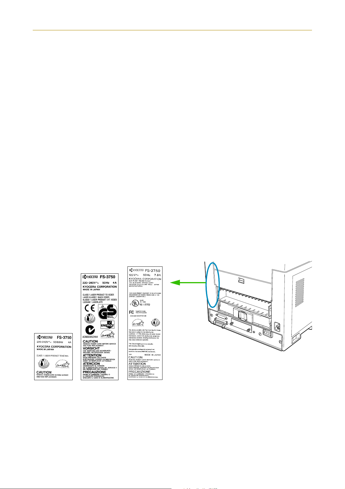
The labels shown are affixed to the
FS-3750. Similar labels are affixed
to same location on the FS-1750.
(European/
Asian countries)
(U.S.A./Canada)
v
Page 7

Introduction
CDRH regulations
The Center of Devices and Radiological Health (CDRH) of the U.S. Food and Drug Administration implemented regulations for laser products on August 2, 1976. These regulations apply to laser products manufactured after August 1, 1976. Compliance is mandatory for products marketed in the United States. A label
indicating compliance with the CDRH regulations must be attached to laser products marketed in the
United States.
Ozone concentration
The printers generate ozone gas (O3) which may concentrate in the place of installation and cause an
unpleasant smell. To minimize concentration of ozone gas to less than 0.1 ppm, we recommend you not to
install the printer in a confined area where ventilation is blocked.
IMPORTANT SAFEGUARDS
1. Read all of these instructions and save these instructions for later use.
2. Unplug this product from the wall outlet before cleaning.
3. Do not use this product near water.
4. Do not place this product on an unstable cart, stand, or table. The product may fall, causing serious
damage to the product.
5. Slots and openings in the cabinet and the back are provided for ventilation to ensure reliable operation
of the product and to protect it from overheating, these openings must not be blocked or covered. The
openings should never be blocked by placing the product on a bed, sofa, rug, or other similar surface.
This product should never be placed near or over a radiator or heat register. This product should not be
placed in a built-in installation unless proper ventilation is provided.
6. This product is equipped with a 3-wire grounding type plug, a plug having a third (grounding) pin. This
plug will only fit into a grounding-type power outlet. This is a safety feature. If you are unable to insert
the plug into the outlet, contact your electrician to replace your obsolete outlet. Do not defeat the purpose of the grounding-type plug.
7. Do not allow anything to rest on the power cord. Do not locate this product where persons will walk on
the cord.
8. If an extension cord is used with this product, make sure that the total of the ampere ratings on the
products plugged into the extension cord do not exceed the extension cord ampere rating.
9. Never push objects of any kind into this product through cabinet slots as they may touch dangerous
voltage points or short out parts that could result in a risk of fire or electric shock. Never spill liquid of
any kind on the product.
10. Except as explained elsewhere in User's Manual, do not attempt to service this product yourself.
Removing covers may expose you to dangerous voltage points or other risks. Refer all servicing in those
compartments to service personnel.
11. Unplug this product from the wall outlet and refer servicing to qualified service personnel under the
following conditions:
A—When the power cord or plug is damaged or frayed.
B—If liquid has been spilled into the product.
C—If the product has been exposed to rain or water.
D—If the product does not operate normally when the operating instructions are followed. Adjust only
those controls that are covered by the operating instructions since improper adjustment of other controls may result in damage and will often require extensive work by a qualified technician to restore
the product to normal operation.
E—If the product has been dropped or the cabinet has been damaged.
vi
Page 8

Introduction
Declaration of Conformity (U.S.A.)
Model Number: Page Printer FS-1750/FS-3750
(as tested with enhancement optional units: EF-1, PF-21, DU-21, HS-21
and ST-20 etc.)
Trade Name: Kyocera
Responsible Party: Kyocera Electronics Inc.
Address: 11465 John’s Creek Parkway, Suite #250 Duluth, GA 30097, U.S.A.
Telephone number: 770-623-2150
Fax number: 770-623-2151
Contact person for technical matter: Paul Bosak
Phone: 770-623-2163
Manufacturer's name: Kyocera Corporation, Printer Division
Manufacturer's address: 2-14-9 Tamagawadai, Setagaya Ward,
Tokyo 158-8610, Japan
This device complies with Part 15 of the FCC Rules, Operation is subject to the following two conditions: (1)
This device may not cause harmful interference, and (2) this device must accept any interference received,
including interference that may cause undesired operation.
CE Marking Directive
according to Council Directive 89/336/EEC and 73/23/EEC
Manufacturer's name: Kyocera Corporation, Printer Division
Manufacturer's address: 2-14-9 Tamagawadai, Setagaya Ward, Tokyo 158-8610, Japan
declares that the product
Product name: Page Printer
Model number: FS-1750/FS-3750 (as tested with enhancement optional units:EF-1, PF-21,
DU-21, HS-21 and ST-20 etc.)
conforms to the following product specifications.
EN 55 022:1998 Class B, if operated without PF-7E and without HS-3E
EN 55 022:1998 Class A, if operated with PF-7E and with HS-3E
EN 61 000-3-2:1995
EN 50 082-1:1992
IEC 801-2:1991
IEC 801-3:1984
IEC 801-4:1988
EN 60 950:1992+A1+A2+A3+A4+A11
EN 60 825-1:1994+A11
vii
Page 9

Introduction
The manufacturer and its merchandising companies retain the following technical documentation in anticipation of the inspection that may be conducted by the authorities concerned.
User's instruction that conforms to the applicable specifications
Technical drawings
Descriptions of the procedures that guarantee the conformity
Other technical information
KYOCERA ELECTRONICS EUROPE GmbH
Mollsfeld 12
40670 Meerbusch, Germany
Phone: +49 21 59 918 0
Fax: +49 21 59 918 100
Declaration of Conformity (Australia)
Manufacturer's name: Kyocera Corporation, Printer Division
Manufacturer's address: 2-14-9 Tamagawadai, Setagaya Ward, Tokyo 158-8610, Japan
declares that the product
Product name: Page Printer
Model number: FS-1750/FS-3750 (as tested with enhancement optional units:
EF-1, PF-21, DU-21, HS-21 and ST-20 etc.)
Description of device: This Page Printer Model FS-3750 is the 18ppm (FS-1750 is the 14ppm); A4 size and
utilized plane paper; laser; dry toner etc. The printer can be equipped with several enhancement optional
units as a paper feeder as PF-21, a duplexer as DU-21, a sorter as ST-20 etc.
Conforms to the following product specifications.
AS/NZS 3548: 1995 (EN 55 022:1994 Class B, if operated without PF-7E and without HS-3E)
(EN 55 022:1994 Class A, if operated with PF-7E and with HS-3E)
IEC60950 (EN 60 950:1992+A1+A2+A3+A4)
IEC60825-1 (EN 60 825-1:1994+A11)
The manufacturer and its merchandising companies retain the following technical documentation in anticipation of the inspection that may be conducted by the authorities concerned.
User's instruction that conforms to the applicable specifications
Technical drawings
Descriptions of the procedures that guarantee the conformity
Other technical information.
viii
Page 10

Introduction
The manufacturer has been employed with ISO9001 scheme. The manufacturer has been attested by JQA
and BS.
KYOCERA ELECTRONICS AUSTRALIA PTY., LTD
Unit 6, 112 Talavera Road, North Ryde NSW 2113, Australia
Phone: +61 2-9888-9999
Fax: +61 2-9888-9588
Canadian Department of Communications compliance statement
This Class B digital apparatus complies with Canadian ICES-003.
Avis de conformité aux normes du ministère des Communications du
Canada
Cet appareil numérique de la classe B est conforme à la norme NMB-003 du Canada.
ISO 7779
Maschinenlärminformationsverordnung 3. GSGV, 18.01.1991: Der höchste Schalldruckpegel beträgt 70
dB(A) oder weniger gemäß ISO 7779.
Disclaimer
We shall have no liability or responsibility to customers or any other person or entity with respect to any
liability, loss or damage caused or alleged to be caused directly or indirectly by equipment sold or furnished
by us, including but not limited to, any interruption of service, loss of business or anticipatory profits, or consequential damages resulting from the use or operation of the equipment or software.
ix
Page 11
Introduction
Prolonged Non-Use and Moving the Printer
Prolonged Non-use
If you ever leave the printer unused for a long period of time, remove the power cord from the wall outlet.
We recommend you consult with your dealer about the additional actions you should take to avoid possible
damages that may occur when the printer is used next time.
Moving the Printer
When you move the printer:
❒ Move it gently.
❒ Keep it as level as possible, to avoid spilling toner inside the printer.
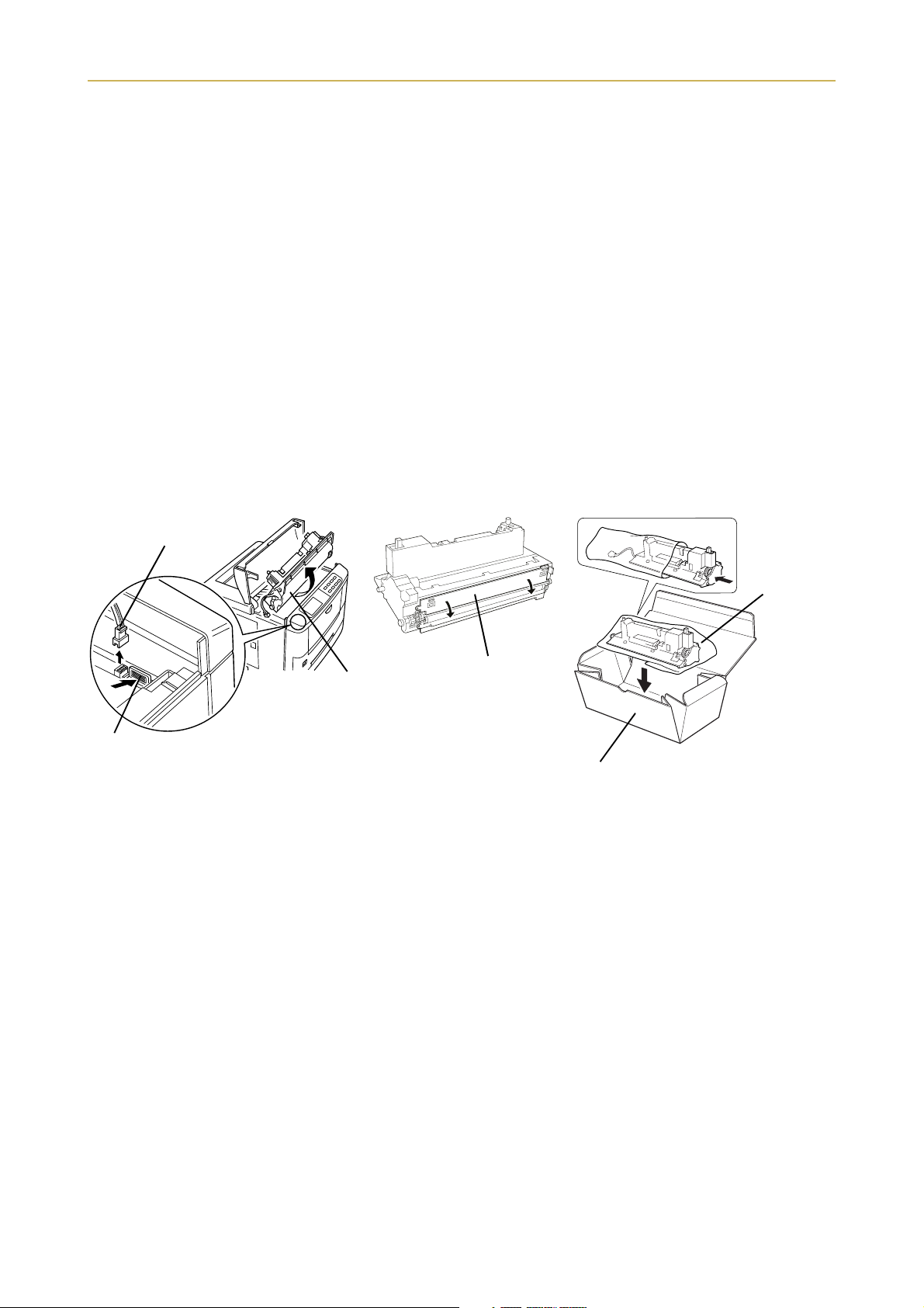
❒ If you need to move the printer to another location, first remove the toner container, developer unit, and
waste toner bottle. After removing the developer unit from the printer, wrap it in the supplied plastic bag
and place it into the box in which the toner container is packaged. Make sure that the waste toner bottle
is securely capped and place it in the plastic bag together with the toner container. Be sure to consult a
serviceman before attempting long-distance transportation of the printer.
(1) Remove the developer unit. (2)
1. Disconnect
Developer unit
2. Push
To reinstall the developer unit in the printer, use the reverse procedure of the above.
Close the protect cover. (3)
Protect cover
Toner container box
Pack the developer unit.
Plastic
bag
(supplied)
x
Page 12
Introduction
As an E
product meets the E
E
NERGY STAR
The basic objective of the E
manufacture and sale of equipment that uses energy more efficiently.
This printer is equipped with a sleep timer function that conforms with the standards of the E
Program. This function makes it possible to reduce the amount of electrical power consumed by the printer.
For maximum power savings, turn off the printer's power supply when not using the printer for extended
periods of time.
For details on the sleep timer function and printer power consumption, refer to the instruction manual provided with the printer.
®
NERGY STAR
NERGY STAR
Program is to reduce environmental pollution by encouraging the
Partner, Kyocera Corporation has determined that this
NERGY STAR
guidelines for energy efficiency.
NERGY STAR
Initial settings of the sleep timer function and power saved using the sleep timer
function:
Initial sleep mode setting
FS-1750 30 minutes (30 minutes) 14 W (30 W)
FS-3750 30 minutes (60 minutes) 16 W (45 W)
The action program Energy 2000
Energy partnership for a sustainable development.
We get further – with all our energy.
Kyocera ECO-PRODUCT
This product has been developed and manufactured with the express interest of reducing the impact on the environment.
Using Kyocera's innovative cartridge free technology, Kyocera has created
an advanced printing sy stem that does not require the wasteful replacement
and disposal of a cartridge.
NERGY STAR
(): E
Power consumption in
sleep mode
program guideline
xi
Page 13

Introduction
Introduction
The Kyocera laser printer has many extremely desirable features. It has been designed to make a contribution to a cleaner environment as well as to represent the latest generation of page printer technology.
Maintenance Features
• Compact design
Thanks to the inboard cassette configuration, the printer requires no more space than the average computer.
• Ultra long life modules
The drum, developer, and fuser have been designed for ultra long life.
• Amorphous silicon drum
The drum has been developed using Kyocera's unique ceramic technology using amorphous silicon.
Print Engine Features
• Superb print quality
Using 1200 dots per inch in "Fast 1200 mode" or "Fine 1200 mode", the printout is close to typeset quality.
Also, with Kyocera Image Refinement (KIR) technology, high quality printing can be achieved even at 600
dpi and 300 dpi.
•High speed
A4 sizes typically print at the rate of 18 (14 for the FS-1750) pages per minute. (Actual time varies according to page complexity)
• Large paper capacity
Approximately 250 sheets can be loaded into the paper cassette, and about 100 sheets can be loaded into
the MP tray.
• Wide variety of print media
As well as standard paper, the printer will print on OHP film, labels and other types of special purpose
media.
•Sleep mode
Conserves energy during the printer's idle periods.
• Ecoprint mode
Extends the toner yield by reducing the amount of toner used on the page.
• Standard bi-directional parallel interface
Supports high-speed data exchange with the computer.
xii
Page 14

Introduction
Software Features
• Wide variety of available fonts
The printer comes with 80 PCL/PS compatible fonts installed.
• Kyocera's own PRESCRIBE 2e printer language
Allows advanced graphic capabilities that allow you to print out any outline shape or solid form, as well
as providing a variety of special effects such as patterned fills, gray-scale shading, a user accessible print
image model, and multiple page orientations and print directions within the same page.
• Automatic rotation of fonts and graphics
Images and fonts are automatically rotated to match the page orientation.
• A wide variety of internal symbol sets
The printer supports most PCL 6 symbol sets.
• Display of printer messages in any of four languages
English, French, German, or Italian. As an option it is also possible to download the messages in other
languages. Please contact your Kyocera dealer.
• Memory card slot for option fonts, macros, forms, etc.
Data in the memory card can be selectively read from the printers control panel.
• Simple network management protocol (SNMP) compliance
Offers network managers complete open network management.
•Kyocera PrintMonitor
Provides network wide management of the Kyocera FS family of laser printers. Refer to the readme file
located in the Kyocera Digital Library CD-ROM (included with the printer) for details.
• PDF417 two-dimensional bar codes
The printer includes the capability that allows the user to implement the two-dimensional stacked bar
code symbology, PDF 417, or Portable Data File 417.
Options
The following options are available for the printer.
DU-20 Duplexer (for FS-3750)
DU-21 Duplexer (for FS-1750/FS-3750)
EF-1 Envelope Feeder
HS-20 Paper Handler/Stacker (for FS-3750)
HS-21 Paper Handler/Stacker (for FS-1750/FS-3750)
HS-3E Bulk Paper Stacker (for FS-3750)
PA-1 Paper Path Adaptor
PA-20 Paper Path Adaptor
PF-20/PF-20mini Paper Feeder (for FS-3750)
PF-21/PF-21mini Paper Feeder (for FS-1750/FS-3750)
PF-7E Bulk Paper Feeder
PT-4 Face-up Output Tray (for FS-1750)
SO-6 Sorter/stacker
ST-20 Bulk Paper Stacker
xiii
Page 15

Introduction
Guide to the Manual
Unless specifically stated otherwise, information in this manual applies to printer models FS-1750/
FS-3750. The printer illustrations and printed samples used in this manual are of the FS-3750.
User's Manual (This booklet)
The User's Manual is this booklet. This manual guides you through the following topics:
❒ Installation
❒ Printer operation
❒ Control panel operations
❒ Fonts
❒ Maintenance and troubleshooting
CD-ROM (Kyocera Digital Library)
The CD-ROM supplied contains the printer User's Manual, PRESCRIBE 2e Programming Manual, and
PDF417 Two Dimensional Bar Code Implementation Manual. To gain access to these documents, insert the
CD-ROM into the appropriate drive and follow the instructions on the insert accompanying the CD-ROM.
To view these documents, you need the Adobe Acrobat software installed in your computer. For details, read
the instructions on the CD-ROM package.
The User's Manual guides you through topics concerning the operations and maintenance of the printer.
The PRESCRIBE 2e Programming Manual explains how to use the PRESCRIBE 2e commands in document files for formatting, and their parameters in detail for experienced users, using pictures and samples.
User's Manual (on CD-ROM):
Includes the text of this manual.
PRESCRIBE 2e Programming Manual (on CD-ROM):
❒ PRESCRIBE 2e command reference
❒ Fonts
❒ Bar codes
❒ Printer permanent parameters
❒ Emulation
PDF417 Two Dimensional Bar Code Implementation Manual (on CD-ROM):
❒ PDF417 overview
❒ PRESCRIBE 2e commands for PDF417
xiv
Page 16

Table of Contents
Table of Contents
Chapter 1 Installing the Printer............................................. 1-1
1.1. Positioning the Printer............................................................1-1
Clearance............................................................................................................ 1-1
Places to Avoid................................................................................................... 1-1
Basic requirements............................................................................................ 1-2
Power Supply ..................................................................................................... 1-3
1.2. Unpacking and Inspection ...................................................... 1-3
List of Shipped Components ............................................................................. 1-4
1.3. Names of Parts........................................................................ 1-5
Front View.......................................................................................................... 1-5
Interior View ...................................................................................................... 1-6
Rear View........................................................................................................... 1-6
1.4. Setting Up and Interfacing .....................................................1-7
1—Open the top cover ....................................................................................... 1-8
2—Install the toner container........................................................................... 1-8
3—Close the top cover ....................................................................................... 1-9
4—Install the waste toner bottle ...................................................................... 1-9
5—Adjusting the paper guides in the cassette and adding paper ................ 1-11
6—Open the paper stopper on the face-down output tray ............................ 1-13
7—Install the face-up output tray (if required) ............................................. 1-13
8—Connect the printer to the computer......................................................... 1-14
9—Attach the power cord ................................................................................ 1-14
10—Print a status page ................................................................................... 1-15
11—Test the interface with the computer...................................................... 1-15
12—Set the emulation mode ........................................................................... 1-15
13—Install the printer driver ......................................................................... 1-16
1.5. MP (Multi-Purpose) Tray Feeding ......................................... 1-19
First Mode (Automatic Manual Feeding) ....................................................... 1-19
Cassette Mode .................................................................................................. 1-19
Duplex Printing from the MP tray ................................................................. 1-19
Selecting the MP Tray ..................................................................................... 1-19
1.6. Memory Card ........................................................................ 1-22
Handling a Memory Card................................................................................ 1-22
1.7. Memory Expansion Installation............................................ 1-23
Removing the Main Circuit Board .................................................................. 1-23
SIMM to be used.............................................................................................. 1-25
Installing and Removing SIMMs .................................................................... 1-25
Testing the Expansion Memory ...................................................................... 1-26
xv
Page 17

Table of Contents
Chapter 2 Operating the Laser Printer..................................2-1
2.1. Control Panel .......................................................................... 2-1
Message Display ................................................................................................ 2-2
Interface Indicator............................................................................................. 2-2
Resolution Indicator .......................................................................................... 2-2
Paper Size Indicator .......................................................................................... 2-3
Copy Indicator.................................................................................................... 2-3
Symbolic Indicators ........................................................................................... 2-4
Control Keys....................................................................................................... 2-5
2.2. Operating Procedures............................................................. 2-6
Switching Power On .......................................................................................... 2-6
Stack Selection................................................................................................... 2-6
Feed Selection .................................................................................................... 2-6
On-line/Off-line Setting ..................................................................................... 2-7
Canceling Printing............................................................................................. 2-7
Status Printout .................................................................................................. 2-8
Form Feed ........................................................................................................ 2-10
2.3. Using the Mode Select Menu ............................................... 2-11
Mode Select Menu............................................................................................ 2-11
2.4. Configuring Interfaces.......................................................... 2-13
Parallel Interface ............................................................................................. 2-13
2.5. RAM DISK .............................................................................. 2-14
Setting the RAM DISK Size............................................................................ 2-14
RAM DISK Operations .................................................................................... 2-14
2.6. Operating a Memory Card.................................................... 2-15
Hints on Writing Fonts to the Memory Card................................................. 2-15
Reading Fonts/Data from a Memory Card ..................................................... 2-15
Writing Data to a Memory Card ..................................................................... 2-15
Deleting Data from a Memory Card............................................................... 2-16
Formatting a Memory Card ............................................................................ 2-17
Printing a list of data names........................................................................... 2-17
2.7. Setting Custom Sizes ............................................................2-18
2.8. Setting the Paper Type ......................................................... 2-19
Making Settings............................................................................................... 2-20
Paper Type User Setting ................................................................................. 2-20
2.9. Sleep (Ecopower) Mode........................................................ 2-22
xvi
2.10. Dumping Received Data ....................................................... 2-23
2.11. KIR 2 Level............................................................................ 2-24
2.12. Ecoprint Mode ...................................................................... 2-25
2.13. Resource Protection .............................................................. 2-26
Page 18

Table of Contents
2.14. Adjusting the Print Density .................................................. 2-26
2.15. Setting the Audio Warning (Buzzer)..................................... 2-27
Chapter 3 Fonts....................................................................... 3-1
3.1. Internal Fonts..........................................................................3-1
3.2. List of Fonts ............................................................................ 3-2
Chapter 4 Maintenance .......................................................... 4-1
4.1. Toner Kit Replacement ........................................................... 4-1
Toner Kit to be Used.......................................................................................... 4-1
Supplying Toner................................................................................................. 4-1
Replace the Waste Toner Bottle........................................................................ 4-4
4.2. Cleaning.................................................................................. 4-6
Main Charger Unit ............................................................................................ 4-6
Paper Feed Unit................................................................................................. 4-8
Chapter 5 Troubleshooting....................................................5-1
5.1. General Guide ......................................................................... 5-1
5.2. Power Problems ...................................................................... 5-2
5.3. Interface Problems.................................................................. 5-2
5.4. Print Quality Problems............................................................ 5-3
Completely blank printout ................................................................................ 5-3
All-black printout............................................................................................... 5-3
Dropouts, horizontal streaks, stray dots .......................................................... 5-4
Black or white vertical streaks ......................................................................... 5-4
Faint or blurred printing................................................................................... 5-5
Grey background................................................................................................ 5-5
Dirt on the top edge or back of the paper ......................................................... 5-6
Characters out of position ................................................................................. 5-6
5.5 Indicators and Messages ........................................................5-7
Indicators ........................................................................................................... 5-7
Maintenance Messages...................................................................................... 5-8
Error Messages ................................................................................................ 5-10
5.6. Correcting a Paper Jam......................................................... 5-12
xvii
Page 19

Table of Contents
Appendix A Printer Specifications.........................................A-1
Appendix B Paper Selection................................................... B-1
B.1. General Guidelines..................................................................B-1
Paper Availability ..............................................................................................B-1
Paper Specifications ..........................................................................................B-1
B.2. Selecting the Right Paper ....................................................... B-2
B.3. Special Paper ..........................................................................B-4
Overhead Projection (OHP) Film......................................................................B-5
Adhesive-Backed Labels....................................................................................B-5
Appendix C Host Computer Interface ................................... C-1
C.1. Parallel Interface .....................................................................C-1
Parallel interface communication modes .........................................................C-1
Interface Signals................................................................................................C-2
C.2. RS-232C/RS-422A Interface .....................................................C-4
RS-232C interface ..............................................................................................C-4
RS-422A interface ..............................................................................................C-5
C.3. RS-232C/RS-422A Protocol ......................................................C-8
PRESCRIBE 2e FRPO D0 command................................................................C-9
C.4. RS-232C Cable Connection ..................................................... C-9
Preparing an RS-232C Cable ............................................................................C-9
Connecting the Printer to the Computer........................................................C-10
Index..................................................................................Index-1
Mode Select Menu ........................................................Last page
xviii
Page 20
1.1. Positioning the Printer
Chapter 1
Installing the Printer
This chapter explains how to unpack and install the printer. The topics covered are:
Positioning the printer
Unpacking and inspection
Names of parts
Setting up and interfacing
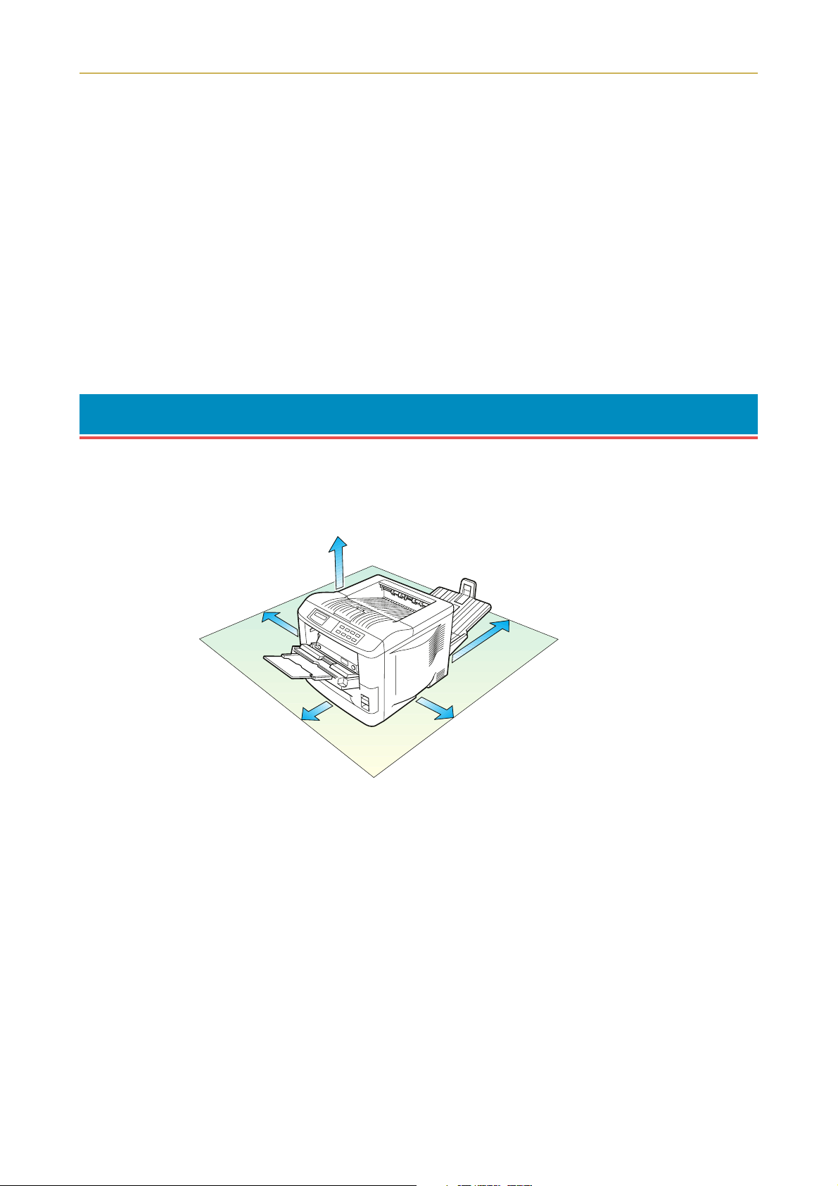
1.1. Positioning the Printer
Clearance
Allow at least the necessary minimum clearance around the printer (see below). A total space of 92 cm by
61 cm by 138 cm (36 by 24 by 54 inches) is needed.
30 cm (12 inches)
30 cm (12 inches)
40 cm (16 inches)
[20 cm (8 inches) when the
face-up output tray* is not
installed.]
* Optional with the FS-1750
60 cm (24 inches)
25 cm (10 inches)
Places to Avoid
Avoid installing the printer in locations subject to:
❒ Direct drafts of hot or cold air
❒ Direct drafts from outside (Avoid locations near doors leading outside.)
❒ Sudden temperature or humidity changes
❒ Sources of high temperature, for example, near stoves or radiators
❒ Excessive dust
❒ Vibration
❒ Ammonia or other harmful fumes. (If you are planning to fumigate the room, or make liberal use of insec-
ticide, remove the printer first!)
❒ Excessive sunlight or humidity
❒ Lack of ventilation
❒ Low air pressure, e.g., located more than 2000 meters (6500 feet) above sea level
1-1
Page 21
1.1. Positioning the Printer
Basic requirements
The printer will work best if it is installed in a location that is:
❒ Near the computer
If the parallel interface is used to connect the printer to the computer, the connecting cable should be
shielded type and not be longer than 3 meters (10 feet).
❒ Level and well supported
Place the printer on a sturdy table or desk. Do not place the printer on an unstable cart, stand, or table. The
printer may fall, causing injury, or serious damage to the printer.
❒ Near an AC wall outlet, preferably one that can be used for the printer alone (see section Power Supply on
next page).
Power requirements are:
Voltage
Frequency
Current capacity
The outlet should be earthed, or an adapter should be used.
If an extension cord is used, the total length of the power cord plus extension should be 5 meters (17 feet) or
less.
❒ Well ventilated, not too hot or cold, and not too damp or dry
Temperature
Humidity
If you install the printer where the temperature or humidity is outside the above ranges, you may not get
the best print quality, and there will be an increased chance of paper jams.
120 V (U.S.A./Canada), 220 V to 240 V (European countries), ±10 % at each voltage
60 Hz (120 V), ±2 %
50 Hz/60 Hz (220 V to 240 V), ±2 %
FS-1750: Max. 5.8 A at 120 V, or Max. 3 A at 220 V to 240 V
FS-3750: Max. 7.8 A at 120 V, or Max. 4 A at 220 V to 240 V
10°C to 32.5°C (50°F to 90.5°F)
20% to 80%
1-2
Page 22
1.2. Unpacking and Inspection
Power Supply
The printer should not be on the same power circuit as an air conditioner, fluorescent light, copier, or shredder, because these devices generate electrical noise on the power line. If it must share a power circuit with
equipment like this, a high-frequency noise filter or isolation transformer is advisable. (Filters and transformers are available commercially.)
Avoid using plug multipliers to connect a large number of devices on the same circuit as the printer.
If the power from the outlet itself appears to be unstable, a line stabilizer should be used. In places where
the voltage tends to fluctuate, it may be necessary to install a voltage regulator.
As the disconnect device is not incorporated in the printer’s AC primary circuit, an easily
accessible socket outlet must be provided near the equipment.
If the printer is used with the optional Sorter (SO-6) or Stacker (ST-20), in order to avoid shortcircuiting, it should be ensured that these devices are plugged securely into their respective
power outlets.
Da kein Trennschalter in den Wechselstrom-Primärkreis des Druckers eingebaut ist, muß
eine leicht zugängliche Steckdose in der Nähe des Gerätes vorhanden sein.
Wenn der Drucker mit dem gesonderten Sorter (SO-6) oder Stapler (ST-20) verwendet wird,
muß darauf geachtet werden, daß diese Geräte einwandfrei an separate Steckdosen angeschlossen sind, um Kurzschluß zu vermeiden.
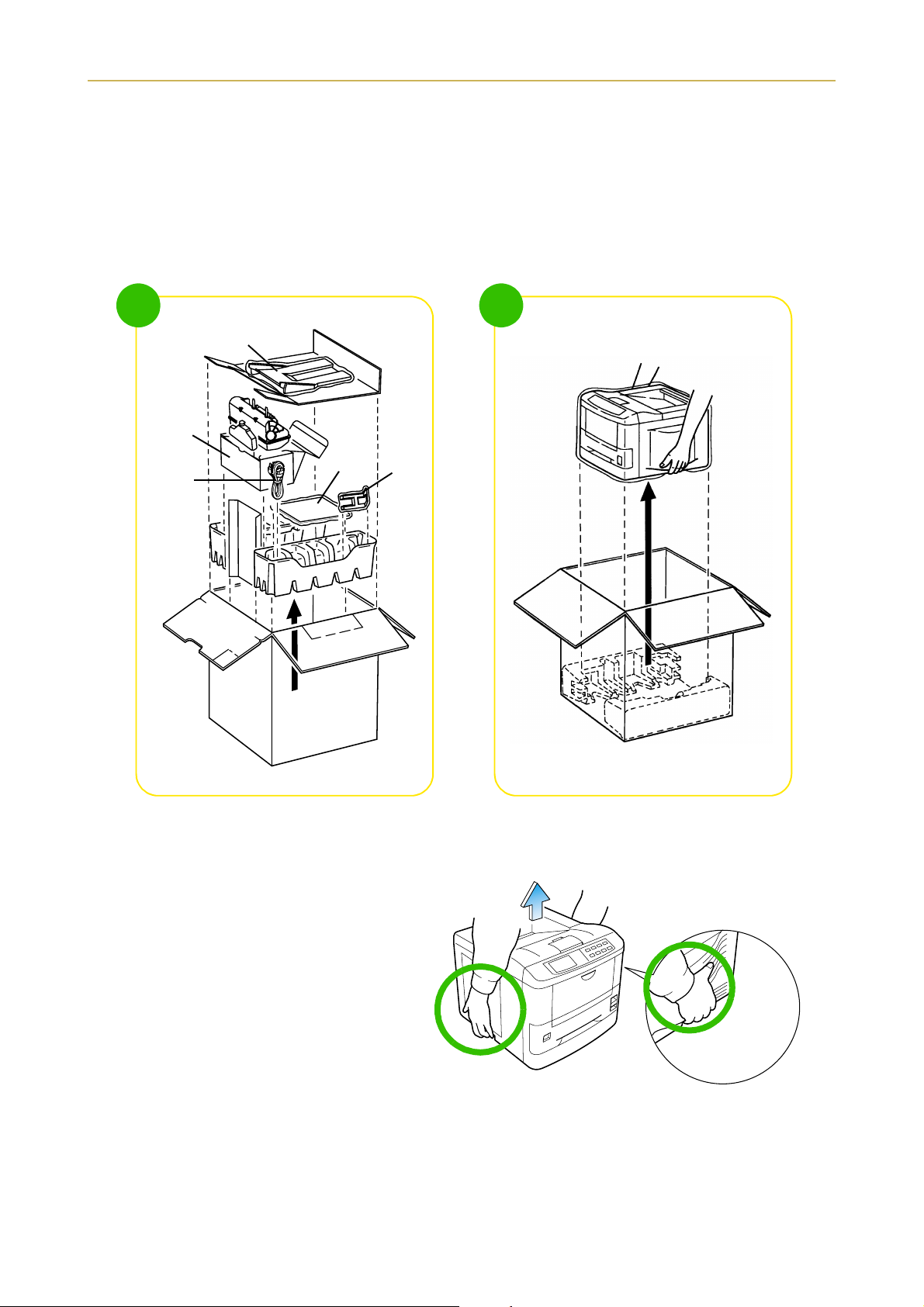
1.2. Unpacking and Inspection
The printer is packed a s shown below. Unpack the printer following d iagrams 1 and 2 on the next page. While
unpacking it, check that the listed parts are all accounted for.
Examine the package for any signs of damage that may have been caused during transportation. If the carton is found to be badly damaged, leave the carton unopened and immediately notify the dealer from whom
you purchased the printer.
Save the box and other packing materials in case you have to repack the printer for transportation at a later
date.
1-3
Page 23
1.2. Unpacking and Inspection
List of Shipped Components
❒ (A) Face-up Output Tray (FS-3750 only)
❒ (B) Toner Kit (Box for the Developer Unit)
❒ (C) Power Cord
❒ (D) User's Manual and Kyocera Digital Library (CD-ROM), including the printer drivers and manuals.
❒ (E) Paper Stopper (FS-3750 only)
1
(B)
(C)
(A)
(D)
2
Printer
(E)
To remove the printer from the box, grasp the handholds on either side of the printer. Lift the printer from
the carton as shown below.
☛
‹ Always use these handholds when-
ever you lift or move the printer.
‹ The handhold on the right side of the
printer doubles as the memory card
slot. Be sure to remove the memory
card first, if inserted, before lifting or
moving the printer.
1-4
Page 24
1.3. Names of Parts
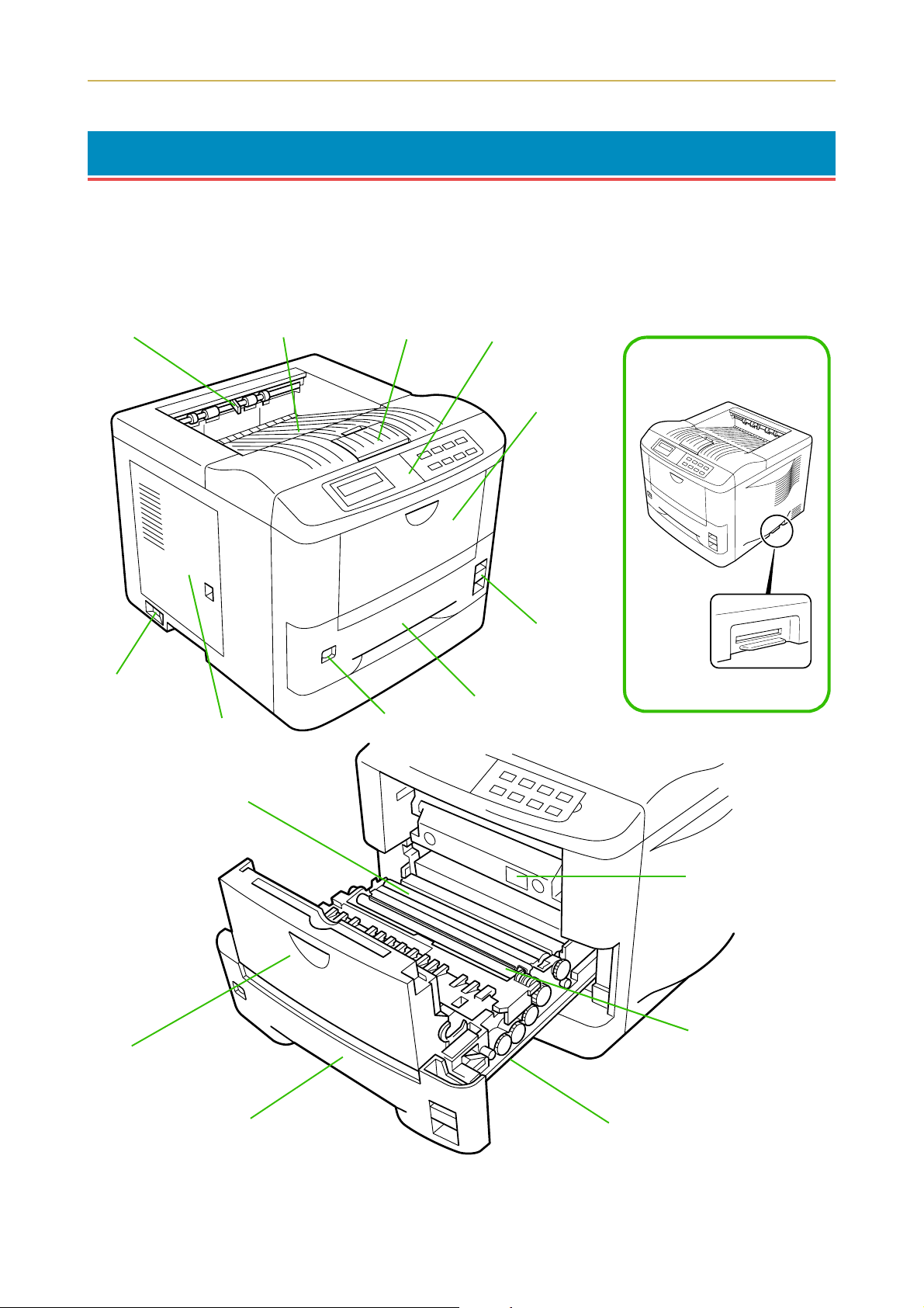
1.3. Names of Parts
This section takes you on a guided tour of the printer, pointing out its major parts. The part names introduced here will be used throughout this manual.
Front View
Paper Full Sensor
(Model FS-3750 only)
Power Switch
Side Cover
Face-down
Output Tray
Paper Stopper Control Panel
MP
(Multi-Purpose)
Tray
Paper Feed Unit
Release Lever
Memory Card Slot
Paper Cassette
Size Window
MP Tray
Transfer Roller
Option Paper Feeder
Connector*
Registration Roller
Paper Cassette Paper Feed Unit
1-5
Page 25
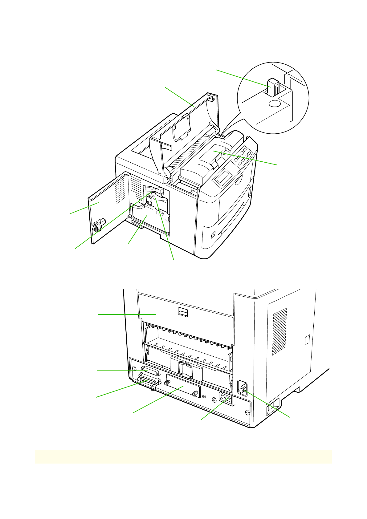
1.3. Names of Parts
T
Interior View
oner Container Release
Lever (Green)
Top Cover
Toner Container
Side Cover
Cleaner Knob (Green)
Rear View
Rear Cover
Serial Interface
(RS-232C/RS-422A)
Connector
Waste Toner Bottle
Main Charger Unit
Parallel Interface Connector
Option Interface Slot Cover
*: To protect the printer against static discharge, the connector must be covered with the supplied protective cap when
not in use.
Option Paper
Handler/Stacker Connector*
Power Cord
Receptacle
1-6
Page 26

1.4. Setting Up and Interfacing
1.4. Setting Up and Interfacing
Before you can use the printer for the first time, you must set up the printer by installing the printer components and interfacing with the computer. The steps to be followed in setting up are:
Open the top cover.
1.
Install the toner container.
2.
Close the top cover.
3.
Install the waste toner bottle.
4.
Adjusting the paper guides in the cassette and adding paper.
5.
Open the paper stopper on the face-down output tray.
6.
Install the face-up output tray (if required).
7.
Connect the printer to the computer.
8.
Attach the power cord.
9.
Print a status page.
10.
Test the interface with the computer.
11.
Set the emulation mode.
12.
Install the printer driver.
13.
1-7
Page 27
1.4. Setting Up and Interfacing
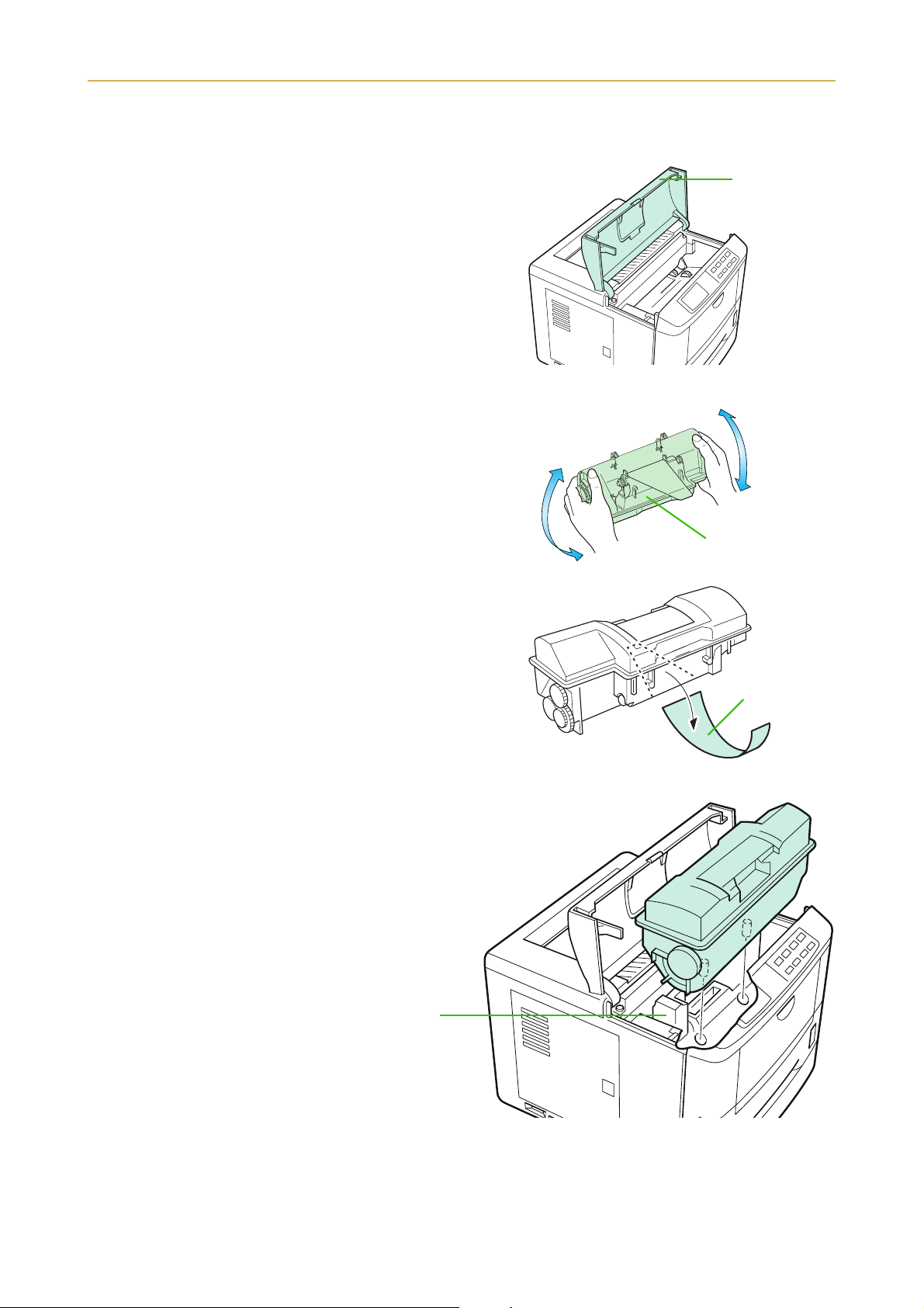
1—Open the top cover
Remove the packing tape from the printer.
1.
Open the printer top cover all the way.
2.
2—Install the toner container
Take the toner container from the toner kit.
1.
With the label side down, thoroughly shake the
2.
toner container (in the direction of the arrow) ten
times or more to loosen and mix the toner inside.
Top Cover
The bottom of the toner container is sealed with a
3.
sealing strip. Peel off the seal on the toner container
and carefully pull off and dispose of the sealing
strip.
☛ Be sure to peel the seal off the toner container
before the toner container is fitted into the developer unit.
Install the toner container on the developer
4.
as show in the diagram.
Toner Container
Sealing strip
1-8
Developer Unit
Page 28
1.4. Setting Up and Interfacing
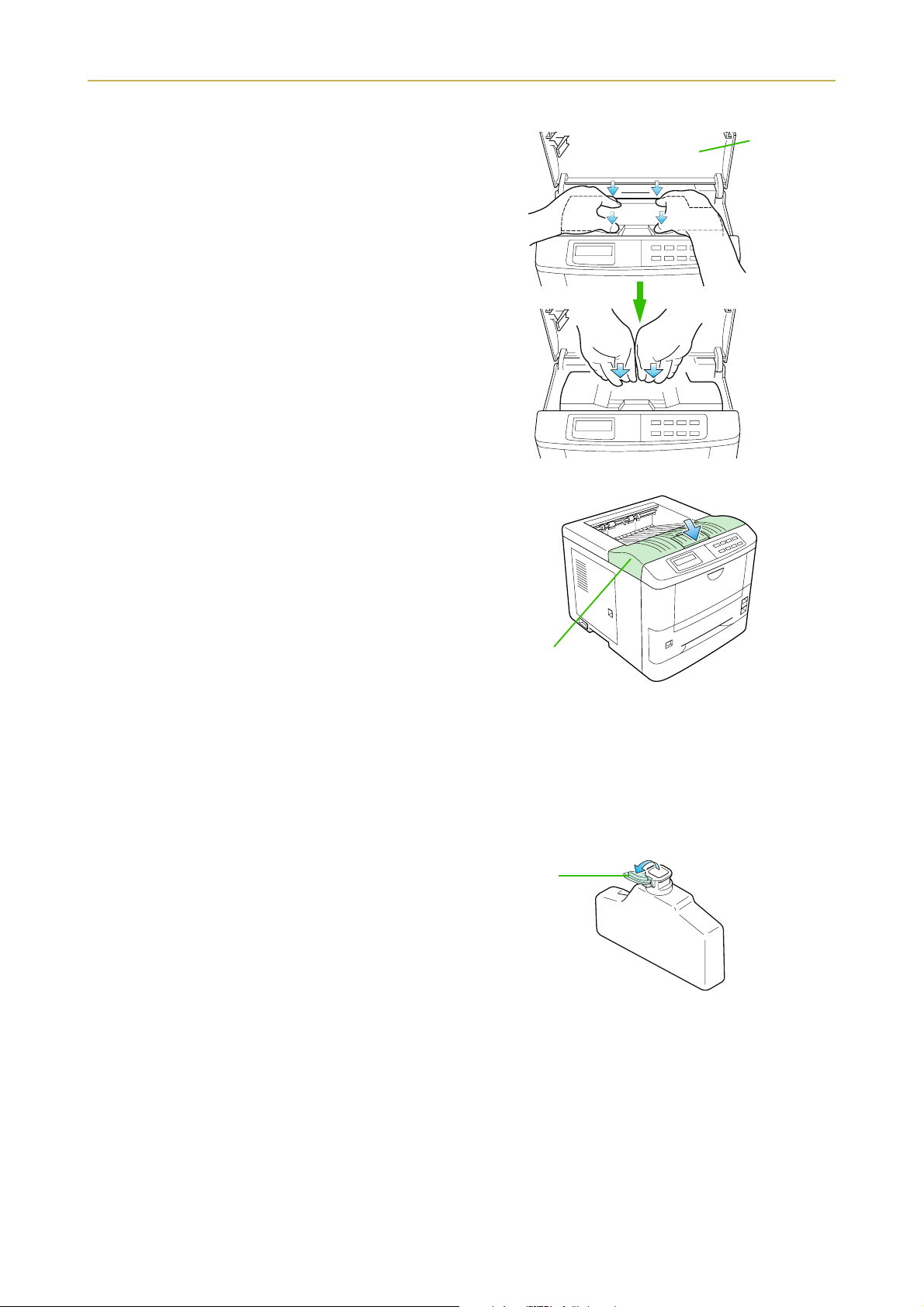
5. When the toner container is installed correctly on
the developer, push the top of the container unit
("PUSH HERE") until it locks in.
☛ Make sure that the toner container is properly
locked in the printer.
3—Close the top cover
Close the top cover by pressing the arrowed part in this
diagram.
Top Cover
Top Cover
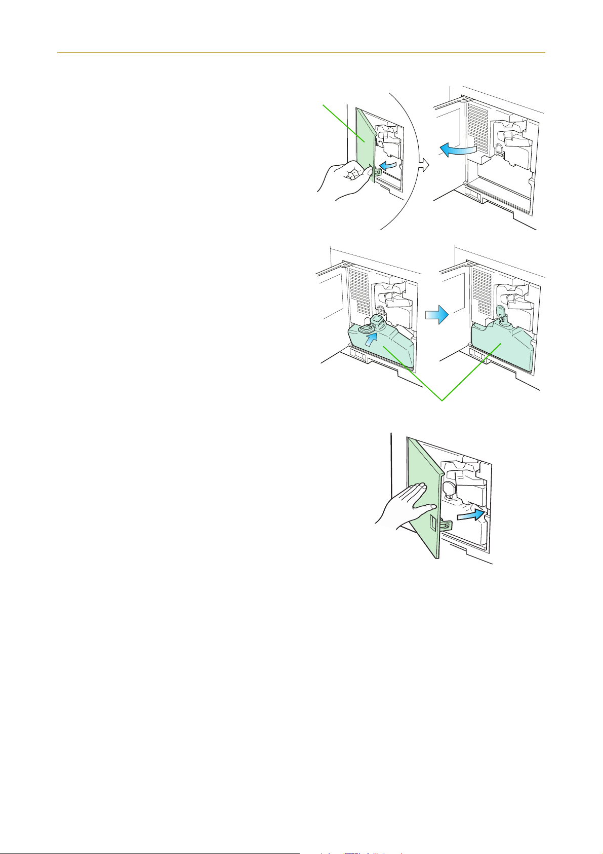
4—Install the waste toner bottle
The waste toner bottle is in the toner kit supplied with the printer. The waste toner bottle must be installed
in the printer.
Install the waste toner bottle in the printer as follows.
1. Take the waste toner bottle from the toner kit sup-
plied.
☛ Do not cap the waste toner bottle.
Cap
Waste Toner
Bottle
1-9
Page 29
1.4. Setting Up and Interfacing
2. Open the side cover on the left side of the printer.
3. Insert the waste toner bottle with the bottle tilted
slightly towards you as shown in the figure.
Side Cover
4. Ensuring that it is correctly inserted, close the side
cover.
Waste Toner Bottle
1-10
Page 30
1.4. Setting Up and Interfacing
B
P
l
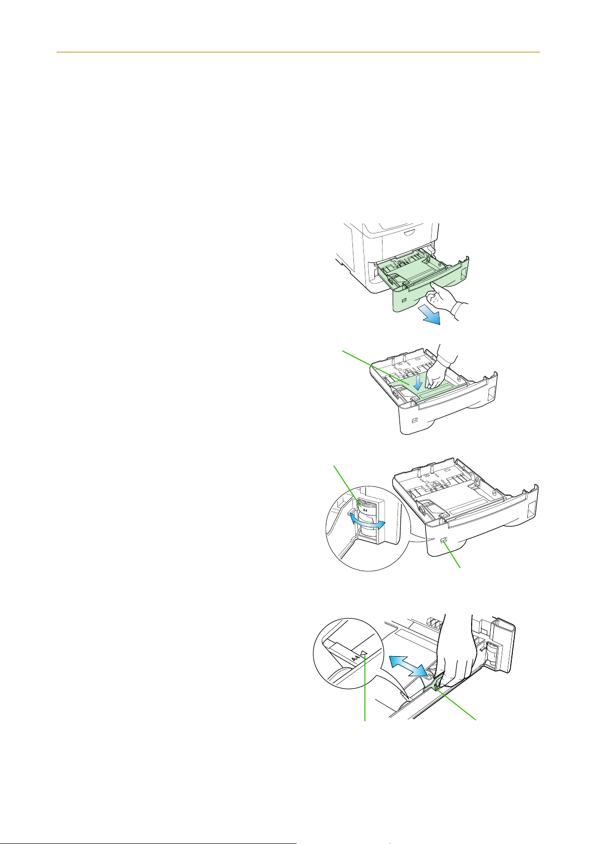
5—Adjusting the paper guides in the cassette and adding paper
The paper cassette provided with the printer can accommodate paper sizes from A5 to legal, by adjusting the
position of the paper guides and the paper stopper. Paper sizes that are not standard sizes (custom sizes) but
within the size limitations can also be loaded into the cassette. When loading custom sizes into the cassette,
the size must be input into the printer on the control panel. (Refer to 2.7. Setting Custom Sizes) Standard
size paper settings are indicated as fixed positions in the cassette.
☛ ‹ Before adding paper, remove the paper cassette all the way from the printer.
‹ Read the paper manufacturer's instructions concerning handling of the paper.
Remove the paper cassette from the printer, and
1.
place it on a flat, stable surface.
Paper Cassette
Push the bottom plate down until it locks.
2.
Turn the paper size dial so that the size of the paper
3.
you are going to use appears in the paper size window.
☛ When the paper size dial is set to "Custom" the
paper size must be set into the printer on the control panel. See 2-7 Setting Custom Sizes for the
setting procedure.
Adjust the paper guide and paper stopper posi-
4.
tions.
Move the paper guides while lifting the green latch
on the right. Set the triangular markings on the
guides to the size of paper that you are to use as
indicated.
ottom Plate
aper Size Dia
Paper Size Window
Triangle Mark
Paper Guide
1-11
Page 31

1.4. Setting Up and Interfacing
Move the paper stopper while pushing on the green
button at the back. Set the paper stopper to the size
of paper that you a re to use as indicated in the small
windows on the floor of the cassette.
When using custom size paper, move the paper
guides and paper stopper all the way out, insert the
paper, and then adjust the paper guides and paper
stopper to suit. Adjust them so that they are in light
contact with the paper.
5. Tap the edges of the paper to align the sheets
neatly. Set the paper in the cassette as shown. The
side of paper that faces downward in the cassette is
the one on which printing is done.
Do not load paper into the cassette higher than the
limitation mark on the right (The cassette should
hold approximately 250 sheets of paper with a 0.1
mm thickness.)
6. Set the stack of paper so that it is under the clips as
shown.
Paper Stopper
When loading the paper,
make sure the leading
edge of paper is not bent
in any way.
Limitation
mark
Clip
7. Hold the cassette as shown in the illustration and
insert the paper cassette into the printer cassette
slot. Push it straight in as far as it will go.
☛ If the paper size dial on the cassette is not set to
match the size of paper inserted, a paper jam may
result.
1-12
Page 32

1.4. Setting Up and Interfacing
6—Open the paper stopper on the face-down output tray
Open the paper stopper as shown right.
Paper Stopper
7—Install the face-up output tray (if required)
☛ This face-up output tray is a separate option (PT-4) with the FS-1750.
If you want the printed pages stacked face-up (in reverse order), mount the face-up output tray as follows.
Depending on the size of the paper you use, mount the paper stopper on the face-up output tray as shown
below.
Paper Stopper
Legal Size
A4 Size
Letter Size
Face-up Output
Tray
1-13
Page 33

1.4. Setting Up and Interfacing
8—Connect the printer to the computer
The printer has two computer cable connectors and a slot for installing an option interface. The one marked
" " is for a parallel (Centronics standard) interface. The one marked "IOIOI" is for a serial (RS-232C/
RS-422A) interface. You may use whichever is convenient for your computer, with the option interface, if
you have already have one installed. All interface connectors can be used simultaneously with different computers.
Serial (RS-232C/RS-422A)
Interface Connector
Parallel Interface
Connector
☛ Only connect or disconnect cables to the connectors while the printer and computer power are
switched off.
Option Interface
Slot Cover
Parallel interface
Plug one end of the cable into the connector marked Parallel on the printer. Close the clips on both sides to hold
it in place.
Plug the other end into a parallel (Centronics) interface
connector on your computer. This connector is usually
marked PRINTER.
See Appendix C for more details about the parallel
interface.
Printer Cable
Clips
Rear Panel
Serial interface
The serial interface of this printer is set to RS-232C mode before leaving the factory, but can also be set to RS422A mode to suit your operating environment. Follow the instructions in Appendix C.
9—Attach the power cord
Check that the power switch is off.
1.
Plug one end of the power cord into the receptacle at
2.
the back of the printer.
Plug the other end into the wall outlet.
3.
Power Cord
Power Cord
Receptacle
1-14
Page 34

1.4. Setting Up and Interfacing
10—Print a status page
Test that the printer works by printing out a status page as follows.
Switch on the printer's power. The message display should indicate 6HOIý WHVW.
1.
☛ When the printer is first switched on after installation, there will be a delay of several minutes
(approx. 6 to 7 minutes) before the printer gets ready to print. During this period, the message display shows 3OHDVHýZDLW.
Wait until the ON LINE indicator is also lit and the message display indicates 5HDG\.
2.
Press the STATUS key. The printer should print a page listing the positions of margins, memory alloca-
3.
tion, and other information.
A sample status printout is shown in Chapter 2.
11—Test the interface with the computer
Test that the printer and computer are correctly connected. If you have connected the printer and computer
with a parallel interface cable, follow the procedure below.
Check that the printer's message display indicatesý5HDG\ and that the ON LINE indicator is ON.
1.
Boot the computer in DOS mode, or set the computer to DOS (prompt) mode.
2.
At the DOS prompt, type the following.
3.
ECHO !R! STAT; EXIT;>PRN
If the printer prints a status page, the computer and printer are connected correctly. For details on the status
page, refer to Chapter 2.
If you do not get this result, check that the cable is securely plugged in at both ends, and repeat the test. If
you still do not get the right result, you may have a defective or improperly-wired cable. Try using a different
cable.
12—Set the emulation mode
The printer emulates the operation of five other printers. It is factory-set to emulate the PCL 6 at power-up.
If you primarily use software that supports PCL 6, or that supports the Kyocera printer itself, the factory
setting is the one you want. If you primarily use software that supports another printer, it is convenient to
change the printer's power-up emulation mode.
The emulation mode can be changed from the printer control panel. To change the emulation mode, refer to
the Mode Select Menu diagram on the last page of this manual.
1-15
Page 35

1.4. Setting Up and Interfacing
13—Install the printer driver
Printer drivers are provided for using the printer with Windows 95, Windows 98, or Windows 3.1. Use the
Kyocera Digital Library CD-ROM supplied with the printer. To install the printer driver, proceed as follows.
Reference to the Windows manual is also recommended.
Windows 95/Windows 98
The automatic installation screen appears when the CD-ROM for the printer is inserted into the computer,
if the computer is set for CD aut o-run. Proceed with the installati on according to the instructions that app ear
on the screen. Read the explanation below for information about the main screens during installation.
Select FS-3750 or FS-1750 from this screen.
The types of drivers are shown below. Select the driver that you need. (When you click an explanation
appears below the box.
Depending on the computer, installation screens may not appear. If this happens, install the printer driver
according to the procedure below.
1-16
Page 36

1.4. Setting Up and Interfacing
1. Insert the supplied CD-ROM (Kyocera Digital Library) into the CD-ROM drive of the computer.
2. Click on Start with the mouse on the Windows95/98 Task Bar, and align the cursor with Settings. Click
on Printers among the items displayed.
Start button
Windows 95 Windows 98
3. The printer folder will open. Double click on Add printer.
Windows 95 Windows 98
4. The Printer Wizard screen will appear. Click on Next >.
5. A screen for selecting the printer to be connected will appear. Select the most appropriate printer and
click on Next.
6. Next, Click the manufacturer and model of your printer.... screen will appear. At this point, select Have
Disk ... located at the lower right. (See the figure for Step 7.)
7. A screen for installing from floppy disk will appear. Copy manufacture's files from inside the box, or
input one of the following directories:
(Standard PCL5E driver)
[CD-ROM Drive Name]:\drivers\[Language]\pcl\9x
(Standard PCLXL driver)
[CD-ROM Drive Name]:\drivers\[Language]\pcl\9x\enhanced
1-17
Page 37

1.4. Setting Up and Interfacing
(Standard KPDL driver)
[CD-ROM Drive Name]:\drivers\[Language]\kpdl\9x
8. Select Kyocera FS-1750 or Kyocera FS-3750 click on Next >, and follow the on-screen instructions to
install. Once the driver has been properly installed, a Kyocera printer icon will be added to the printers
folder.
☛ When printing under Windows 95/98, be sure to set the emulation of this printer to PCL 6 (default
setting).
Windows 3.1
To install the printer driver for Windows 3.1, proceed as follows:
1. Insert the Kyocera Digital Library CD-ROM in your CD-ROM drive.
2. Start Windows on your computer.
3. Double click on Control Panel.
4. Double click on Printers.
5. Click on Add.
6. Click on Install.
7. Select Install Unlisted or Updated Printer under List of Printers.
8. Click Install.
9. Select the drive into which you inserted the Kyocera Digital Library CD-ROM, and then select one of
the following directories.
(Standard PCL5E driver)
[CD-ROM Drive Name]:\drivers\[Language]\pcl\3x
(Standard PCLXL driver)
[CD-ROM Drive Name]:\drivers\[Language]\pcl\3x\enhanced
(Standard KPDL driver)
[CD-ROM Drive Name]:\drivers\[Language]\kpdl\3x
Click OK and follow the instructions that appear on the screen.
10. When the driver is installed, click on Close to close Control Panel.
1-18
Page 38

1.5. MP (Multi-Purpose) Tray Feeding
1.5. MP (Multi-Purpose) Tray Feeding
The MP tray is incorporated on the front of the printer. It can be used in one of two modes: first mode or
cassette mode. The MP tray can hold about 100 sheets of paper (A4 size, 0.1 mm thickness).
If you set a full number of sheets for sizes bigger than A4, it could cause a paper jam. In this case, set a lower
number of sheets than the full amount, confirm that there will be no paper jams and then commence printing.
First Mode (Automatic Manual Feeding)
The printer automatically feeds any paper placed on the MP tray even if another paper source is selected.
After all paper in the MP tray is printed, paper will be fed from the paper source originally set. (This is the
factory set default.)
Cassette Mode
The cassette mode provides faster printing speed than the first mode. Approximately 100 sheets of paper
can be continuously fed in this mode.
Duplex Printing from the MP tray
In first mode, be sure to set the MP tray to the same paper size and paper type as set for the current cassette.
If the paper size or type differs, a paper jam may result. Also note that it is not possible to select the MP tray
as the current cassette and perform duplex printing. We therefore recommend that duplex printing be performed from the paper cassette. An optional duplexer (DU-21) is required to perform duplex printing.
Selecting the MP Tray
Taking hold of the front of the printer as shown in
1.
the figure, open the MP tray by pulling towards
you.
Withdraw the sub tray as shown in the diagram.
2.
MP Tray
Sub Tray
1-19
Page 39

1.5. MP (Multi-Purpose) Tray Feeding
3. Raise the paper protector bar until it locks in the up
position. Then adjust the paper guides to the size of
the paper being fed.
Protector Bar
Paper Guides
4. Check that the message 5HDG\ is displayed in the printer's message display, and that the ON LINE
indicator is lit.
5. Set the paper source to the multi-purpose tray by pressing the FEED key until the message display indi-
cates 03ý WUD\. The multi-purpose tray indicator on the control panel will flash, and $GGýSDSHU
will be displayed.
6. Press the MODE key. Then use + or – keys to display 3DSHUý KDQGOLQJý ýý !.
7. Press the (Form Feed) key to display !03ýWUD\ýVL]H or !ý03ýWUD\ý W\SH, then press the ENTER
key so you can set the paper size or type to be fed from the MP tray. See Mode Select Menu at the end of
this manual.
The following pages explain the use of the MP tray in the Cassette Mode and First Mode.
First Mode (Automatic Manual Feeding)
The printer automatically feeds the paper placed on the MP tray regardless of the current paper source selection. To use the first mode (automatic manual feeding mode), simply place a sheet of paper on the MP tray
in the same manner as above, even while the printer is presently feeding the paper in the printer's cassette.
1. Press the MODE key. Then use + or – keys to display 3DSHUý KDQGOLQJý ýý !.
2. Press the (Form Feed) key to display !03ý WUD \ýPRGH.
3. After pressing the ENTER key, the mode display is changed by pressing the + and – keys. Display )LUVW
and then press the ENTER key.
!03 WUD\ PRGH
)LUVW
4.
Press the EXIT key.
☛ The printer will not switch to light the MP tray indicator while the paper is fed manually using the
automatic manual feeding mode.
1-20
Page 40

1.5. MP (Multi-Purpose) Tray Feeding
Cassette Mode
1. Press the MODE key to display 3DSHUý KDQGOLQJý ý ý!.
2. Press the (Form Feed) key to display !03ý WUD \ýPRGH.
3. After pressing the ENTER key, the mode display is changed by pressing the + and – keys. Display
&DVVHWWH and then press the ENTER key.
!03 WUD\ PRGH
&DVVHWWH
4.
Press the EXIT key.
5. Insert the paper so that it is aligned straight in the
tray. About 100 sheets (0.1 mm thickness) can be
inserted at one time.
5HDG\ appears on the message display.
Protector Bar
6. Carefully lower the protector bar, and the paper will be correctly set in the MP tray.
Feeding Envelopes
Envelopes should be fed face up, right side first, as shown below. From the MODE SELECT menu, set the
printer to print in landscape page orientation.
☛ To avoid trouble, we recommend that envelopes
are delivered face-up. Use the STACK key on the
printer control panel to select the face-up tray.
Not all envelopes print well. See Appendix B for details
on suitable types of envelopes.
See page 2-3 for the envelope sizes that can be set.
Envelope
1-21
Page 41

1.6. Memory Card
1.6. Memory Card
A memory card is a microchip card containing, for example, nonresident fonts and/or macros, forms, etc. The
printer reads the contents of the card into its internal memory when power is switched on. The presence of
this data in the printer memory can be confirmed on the status printout.
☛ The maximum card capacity that can be used is 32 Megabytes. The type of the memory card to be
used must be of either flash memory card (+5V type) or SRAM-type and conform to the PCMCIA 2.1
(JEIDA 4.2) standards. Please use a memory card recommended by Kyocera.
The memory card slot is located at the bottom right of the printer.
To insert and use a memory card:
Switch printer power off.
1.
☛ Do not insert or remove a memory card while power is on. If the memory card is removed while the
printer is on, damage could result in the printer's electronics or the memory card.
Insert the memory card in the slot. Insert it face up,
2.
connector end first. Push it in all the way.
Memory Card Slot
[PC CARD (MEMORY)]
Memory Card
Switch printer power on. The printer reads the contents of the memory card during its power-up
3.
sequence. The information (nonresident fonts, etc.) on the memory card is now available for use.
If the memory card information is deleted from the printer's memory during the printing process, it can be
reread by using the mode selection function explained on the last page in this manual.
To Remove the Memory Card:
Switch the power off.
1.
Remove the memory card from the slot.
2.
Handling a Memory Card
A memory card contains sensitive electronic circuits. Treat them with appropriate care.
A memory card is sensitive to electrostatic discharge. Please discharge yourself before touching a memory
❒
card.
Never attempt to force a memory card into its slot.
❒
Never bend a memory card.
❒
Avoid impact. Do not drop a memory card.
❒
Do not touch the terminals of the memory card.
❒
Do not spill water or other liquids on a memory card.
❒
Keep a memory card away from naked flames and other sources of heat.
❒
Do not leave a memory card lying in direct sunlight.
❒
For details regarding the use of the memory card, refer to 2.6. Operating a Memory Card in this manual.
1-22
Page 42

1.7. Memory Expansion Installation
1.7. Memory Expansion Installation
In this section is explained how to expand the printer's memory. Expanded printer memory enables you to
print more complex pages, download more fonts, and define more macros.
It begins by explaining how to remove the main circuit board from the printer, and explains how to install a
SIMM (single in-line memory module) on the main circuit board.
The FS-1750 comes supplied with 8 MB of memory installed, and likewise the FS-3750 comes with 16 MB of
memory supplied. Two slots are provided for expanding the memory in your printer so that more complex
printing can be done, as well as increasing the printing speed. By installing the optional memory card into
your printer, the memory in the FS-1750 can be increased to a maximum of 72 MB, and the FS-3750 can be
increased to a maximum of 64 MB.
☛ ‹ A 16 MB SIMM is installed in one of the SIMM sockets in the FS-3750, so in order to increase the
memory to the maximum 64 MB this SIMM must be changed.
‹ The expansion memory should be installed only by a Kyocera authorized dealer or Kyocera certi-
fied technician. Kyocera shall not be liable for damage due to improper installation of the expansion memory.
The minimum memory requirements for the printer with various options installed are listed in the table
below. Please refer to this table when expanding the printer's memory.
Resolution
Printing condition
PCL 6, duplex mode = None 8 MB 8 MB 8 MB 8 MB
PCL 6, duplex mode = On 8 MB 8 MB 8 MB 12 MB
KPDL, duplex mode = None 8 MB 8 MB 8 MB 8 MB
KPDL, duplex mode = On 8 MB 8 MB 12 MB 12 MB
PCL 6/KPDL resource protection,
duplex mode = None
PCL 6/KPDL, resource protection,
duplex mode = On
300 dpi 600 dpi
– 10 MB 10 MB 10 MB
– 14 MB 14 MB 14 MB
Fast mode Fine mode
1200 dpi
Removing the Main Circuit Board
The main circuit board of the printer is equipped with two sockets for memory expansion. Expansion memory is available in the form of a SIMM.
☛ The following instructions are intended for the technician only.
Notes on Handling the Main Circuit Board and SIMM
Protect the electronics by taking these precautions:
Before touching the main circuit board, touch a water pipe or other large metal object to discharge yourself
❒
of static electricity. While doing the work, it is recommended that you wear an antistatic wrist strap.
Touch the main circuit board and SIMM only by the edges.
❒
1-23
Page 43

1.7. Memory Expansion Installation
Withdrawing the Main Circuit Board from the Printer
☛ Be sure to remove the memory card first if inserted in the printer's memory card slot.
Withdraw the main circuit board completely from the printer as follows:
1. Turn the printer's power off. Unplug the printer's power cable and disconnect the printer from the host
computer.
2. Remove the three screws from the printer's rear
cover.
Power OFF (O)
3. Pull the main circuit board all the way out of the
printer.
☛ Before pulling the main board out, clean an area
on the table, etc., at the back of the printer's rear
panel. Foreign objects, accidentally sticking to
the back of the main board, can cause serious
damage to the printer.
Install the SIMM as described on the next page.
SIMM Sockets
1-24
Page 44

1.7. Memory Expansion Installation
SIMM to be used
See your Kyocera dealer for purchasing information of the SIMMs that are best suited for use with this
printer.
Either 4 MB, 8 MB, 16 MB or 32 MB SIMMs can be used for memory expansion.
Installing and Removing SIMMs
Installing SIMMs
Insert the SIMM into the socket as shown right.
Insert the connector end of the SIMM into the
1.
socket.
Carefully push the board upright until it snaps into
2.
place. Make sure that the catches at the ends of the
socket fit into the holes at the ends of the SIMM
board.
SIMM
Catch
Socket
Catch
1-25
Page 45

1.7. Memory Expansion Installation
Removing SIMMs
To remove a SIMM, carefully pull the end catches
slightly outwards and tilt the SIMM as shown, then pull
the SIMM out of the socket.
Reverse the procedure under Withdrawing the Main
Circuit Board from the Printer to put the main circuit
board back into the printer.
Testing the Expansion Memory
After you have finished installing SIMMs in the printer, test the printer to see if the installation has been
successful.
To test the expansion memory, proceed as follows:
1. Make sure the power switch is off. Plug the power cord into the printer and turn power on.
2. When the printer is on-line, press the STATUS key.
3. If the installation has been successful, the amount of memory shown on the status page will correspond
with the amount of expanded memory. (The factory installed memory size is 8 MB for the FS-1750 and
16 MB for the FS-3750.)
1-26
Page 46

2.1. Control Panel
Chapter 2
Operating the Laser Printer
This chapter explains the printer's control panel and operating procedures. It covers the fundamental information you will need to use the page printer.
2.1. Control Panel
The printer control panel comprises a message display, keys, and indicators, as shown below.
Message Display
Paper Size Indicator
Resolution Indicator
(☛ Page 2-2)
Copy Indicator
Symbolic Indicators
(☛ Page 2-5)
CONTINUE/ Key
ON LINE Key
(☛ Page 2-4)
FORM FEED/ Key
STACK/+ Key
ENTER/STATUS key
- /FEED Key
EXIT/MODE Key
Interface Indicator
(☛ Page 2-2, 3)
CANCEL Key
(☛ Page 2-5)
2-1
Page 47

2.1. Control Panel
Message Display
The message display gives information in the form of short messages. The six messages listed below are displayed during normal warm-up and printing.
Message Meaning
6HOIý WHVW
3OHDVHý ZDLW
5HDG\
3URFHVVLQJ
:DLWLQJ
6OHHSLQJ
&DQFHOOLQJý GDWD
)RUP)HHGý 7LPHý 2XW
The printer is self-testing after power-up.
The printer is warming up and is not ready.
The printer is ready to print.
The printer is receiving data, generating graphics, reading an memory card, or printing.
The printer is waiting for a command that says the job is over before printing the last
page. Pressing the
The printer is in Sleep mode. The printer wakes from Sleep mode whenever a key on the
control panel is pressed, the cover is opened or closed, or data is received. The printer
then warms up and goes online. (The time that it takes the printer to enter Sleep mode
depends on the Sleep Timer setting.)
Data inside the printer is being canceled.
The printer prints the last page after a waiting period.
FORM FEED
key allows you to obtain the last page immediately.
Other messages appear when the printer needs the operator's attention as explained in Chapter 5.
Interface Indicator
The interface indicator shows which of the printer's interfaces is currently active. It uses the following
abbreviations:
3$5 Standard bi-directional parallel interface
6(5 Serial interface (RS-232C/RS-422A)
237 Optional interface
Theý3$5,ý6 ( 5 , orý2 3 7 indicator flashes when the printer is receiving and has received all the data, and
then remains on.
Resolution Indicator
This shows the current printing resolution. The resolutions below can be switched on the control panel. The
default is 1200 dpi (Fast 1200 mode) in the PCL 6 and KPDL emulation mode and 300 dpi in other emulation
modes. The printer's resolution can be selected using the printer's control panel (See the last page in this
manual.). For 1200 dpi, there are two modes, Fast 1200 mode and Fine 1200 mode. See Mode Select Menu at
the end of this manual.
êíí Print at 300 dpi.
çíí Print at 600 dpi.
млнну Print at 1200 dpi (Fast 1200 mode) (Default).
ìëíí Print at 1200 dpi (Fine 1200 mode).
2-2
Page 48

2.1. Control Panel
Paper Size Indicator
This is the paper SIZE indicator which indicates:
❒ the size of the current paper cassette (letter size for the U.S.A. and A4 for European countries).
The following abbreviations are used to indicate the paper sizes.
ISO A4 (21 cm × 29.7 cm)
$é
ISO A5 (14.8 cm × 21 cm)
$è
ISO A6 (10.5 cm × 14.8 cm)
$ç
JIS B5 (18.2 cm × 25.6 cm)
%è
JIS B6 (12.8 cm × 18.2 cm)
%ç
Letter (8-1/2 × 11 inches)
/7
Legal (8-1/2 × 14 inches)
/*
Monarch (3-7/8 × 7-1/2 inches)
02
Business (4-1/8 inches)
%8
*
with only the MP tray feeding or optional envelope feeder (EF-1) installed.
**
with only the MP tray feeding.
**
**
*
*
ISO DL (11 × 22 cm)
'/
ISO C5 (16.2 × 22.9 cm)
&è
ISO B5 (17.6 × 25 cm)
Eè
Executive (7-1/4 × 10-1/2 inches)
(;
Commercial 6-3/4 (3-5/8 × 6-1/2 inches)
úç
Commercial 9 (3-7/8 × 8-7/8 inches)
úä
Japanese Postcard (10 × 14.8 cm)
+$
Return Postcard (20 × 14.8 cm)
2+
Custom Size (14.8 × 21 cm to 21.6 × 35.6 cm)
&8
*
*
**
**
*
*
*
*
☛
While the printer isý 3URFHVVLQJ data to print, the SIZE indicator indicates the paper size selected
by the application software.
Copy Indicator
Indicates the number of copies set in the current interface (ì- äää), and the number is reduced as printing
proceeds.
2-3
Page 49

2.1. Control Panel
Symbolic Indicators
The symbolic indicators light during normal operation and when the
printer needs attention.
Indicator Name Description
Face-down
stack indicator
Flashing:
point, open and remove any jammed paper. See
Lit:
put tray.
Indicates the possibility that paper may be jammed at this
Indicates when printed pages are delivered to the face-down out-
Section 5.6
.
ON LINE
DATA
ATTENTION
Face-up
stack indicator
Toner indicator
Cassette feed
indicator
MP tray indicator
On-line indicator
Data indicator
Attention
indicator
Flashing:
point, open and remove any jammed paper. See
Lit:
tray, or to the option stacker if installed.
Flashing:
Lit:
container.
See
Flashing rapidly:
at this point, open and remove any jammed paper. See
Flashing slowly:
paper.
Lit:
Flashing rapidly:
at this point, open and remove any jammed paper. See
Flashing slowly:
paper.
Lit:
lope feeder if installed.
Flashes when a memory error has occurred. (See
when the printer is on-line. The printer prints received data. Goes off
when the printer is off-line. The printer stores but does not print
received data.
Flashing:
Lit:
written to the memory card.
Flashing:
or the printer is warm ing up (
the message display and consult
Lit:
by the user. (For example, the paper feed cassette is empty.) Read the
message in the message display and consult
Indicates the possibility that paper may be jammed at this
Section 5.6
Indicates when printed pages are delivered to the face-up output
Indicates there is insufficient toner.
Indicates that the printer is out of tone r. Replace with a new toner
Section 4.1
Indicates when paper is fed from the paper feed cassette.
Indicates when paper is fed from the MP tray, or the option enve-
Indicates either that data is being processed, or that data is being
Indicates when a pr oblem or an error occurs which may be clea red
.
Indicates the possibility that paper may be jammed
Indicates that the printer is out of paper. Load more
Indicates the possibility that paper may be jammed
Indicates that the printer is out of paper. Load more
Table 5.3
Indicates data transfer is taking place.
Indicates when the printer needs maintenance attention
3OHDVH ZDLW
Chapter 5
). Read the message on
.
Chapter 5
.
Section 5.6
Section 5.6
.) Lights
.
.
.
2-4
Page 50

Control Keys
The control panel keys are used to configure the printer.
☛ Settings made with these keys effect only the interface cur-
rently in use.
Key Function
ON LINE
Switches the printer on-line and off-line.
2.1. Control Panel
CONTINUE
STACK
+
FORM FEED
CANCEL
EXIT
MODE
–
FEED
ENTER
STATUS
1.Depending on the message being indicated, there are cases where operation will
continue after pressing the
tion will be resumed after pressing this key. (See
2.Used as the key in the mode selection function.
1.Selects whether printed pages are delivered to the face-down, face-up tray, or
optional sorter/stacker (if installed).
2.Lets you access the desired item or enter numeric values. In some of the control
procedures, the (
the sub items.
1.Prints and feeds out one page.
2.Used as the key in the mode selection function.
Abandons a printing job, resets numeric values, or cancels a setting procedure.
1.When pressed during mode selection, terminates the setting and returns to the
5HDG\
2.Used to select the emulation, font, character code set; to read an memory card
and others (See
1.Enables access to the desired item or entering of numeric values. In some of the
control procedures, the (
or exit the sub items.
2.Selects the cassette feed or MP tray feed.
1.Finalizes numeric values and other selections.
2.Prints a page of status information on all interfaces together (The printer must
be on-line.).
condition.
CONTINUE
Section 2.3
CONTINUE
) and (
and the last page in this manual.).
CONTINUE
key. If such a message is displayed, opera-
FORM FEED
) and (
Table 5.3
) keys are used to enter or exit
FORM FEED
)
) keys are used to enter
☛ Most of the panel functions can also be controlled by PRESCRIBE 2e commands or commands gen-
erated by application software. The printer obeys the most recently received printer settings sent
from the application software, or from the printer driver, which take priority over control panel settings.
2-5
Page 51

2.2. Operating Procedures
2.2. Operating Procedures
Switching Power On
Check that the power cord is securely plugged in at both ends.
Check that the printer is connected to the computer. In switching
power on, the general rule is to switch on printer power first, computer power second.
Push the power switch to the ON ( | ) position.
1.
Wait for the printer to warm up. During warm-up the mes-
2.
sage display indicatesý6HOIýWHVW.
At the end of the warm-up period, the ON LINE indicator lights,
and the message display indicatesý 5HDG\. The printer is now
ready to print.
Stack Selection
The STACK key selects the tray to which the printed pages are delivered. The STACK key can be used whenever
the message display indicatesý5HDG\.
Power Switch
Press the STACK key. The selection toggles and is momentarily displayed in the message display as:
)DFHðXSý WUD\
)DFHðGRZQý WUD\
If you have installed the optional sorter or stacker,ý6RUWHU orý%XONý
VWDFNHU will also be displayed.
The current selection is indicated by a green light on the printer symbol above the
key.
Also, if the printer is being used with the optional sorter or stacker, the destination of the paper from each
can be selected.
Feed Selection
The FEED key selects the paper feed cassette [&DVVHWWH] or MP tray
[03 WUD\] (or the option paper feeder[s], if installed) as the paper source. The
FEED key can be used whenever the message display indicatesý5HDG\ orý$G G ý
SDSHU.
Press the FEED key. The selection cycles and is momentarily displayed in the message display as:
&DVVHWWH
õpaper sizeôõpaper typeô
03ý WUD\>MP tray mode@
õpaper sizeôõpaper typeô
If you have installed the optional paper feeder, the cassette in the printer appears on the display as
&DVVHWWHýì, and the cassettes in the paper feeder appear asý &DVVHWWHý ë andý&DVVHWWHý ê.
Also, if the Envelop Feeder or Bulk Feeder is installed then MP tray is not displayed andý( ) orý %XONý
IHHGHU is displayed instead.
The current selection is indicated by a green light on the printer symbol above the key.
2-6
Page 52

2.2. Operating Procedures
On-line/Off-line Setting
By pressing the ON LINE key you can change the printer between the on-line state, in which it prints the data
it receives from the computer, and the off-line state, in which it stores the data for printing later.
Make sure that the message display indicatesý5HDG\.
1.
Press the ON LINE key.
2.
If the printer is on-line, it changes to off-line. If the printer is off-line, it changes back to on-line.
The ON LINE indicator lights when the printer is on-line.
Going off-line may or may not halt communication between the printer and computer, depending on details
of the current interface. While off-line, the printer continues to accept any data that arrives until the current
interface buffer is full, at which point it instructs the computer to stop sending data. Data stored while offline are printed when the printer is returned to the on-line state.
Canceling Printing
Perform the following procedure when you wish to cancel printing after it has begun.
Check if the messageý3URFHVVLQJ is displayed in the message display.
1.
Press the ON LINE key to take the printer offline.
2.
Perform the necessary procedure on the computer to halt printing.
3.
Press the CANCEL key.
4.
The messageý3ULQWý&DQFHO" will appear in the message display and the interface to be canceled
5.
will be displayed.
3DUDOOHO
6HULDO
2SWLRQý (appears only when an optional interface is installed)
Selecting the interface to cancel using the + or – key and then press the ENTER key. Printing from the
6.
interface selected will be stopped.
A few pages may be printed even after the CANCEL key is pressed as remaining data received before the
CANCEL key was pressed is printed.
The messageý 3ULQWý&DQFHO"ý &XU UHQWýMRE will also be displayed when the CANCEL key is
pressed for the purpose of stopping the printing of status pages or font lists from the control panel. When
the ENTER key is pressed, the messageý&DQFHOOLQJý GDWD appears in the message display and
printing stops after the printer finishes printing the current page.
Press the CANCEL key again if you wish to stop the cancellation of printing.
Press the ON LINE key to put the printer back online to continue with other print jobs.
☛ Canceling data from the computer using the CANCEL key will restore temporary settings to their
default values. (The same status resulting from executing the PRESCRIBE 2e RES command.)
☛ It is impossible to cancel printing of just one side when printing in duplex mode using an optional
duplexer (DU-21).
2-7
Page 53

2.2. Operating Procedures
Status Printout
If you want to check the printer's current status, including memory available, and option settings, you can
find the information you need on the status page. To print out a status page, the printer must be on-line.
Proceed as follows:
Make sure the message display indicatesý5HDG\.
1.
Press the STATUS key. The printer prints a page of status information.
2.
The message display indicatesý3URFHVVLQJ during printing of the status page, then returns toý5HDG\.
For a full description of the status page, see next page.
☛ Items and values on the status page may vary depending on the printer model and printer's firm-
ware version.
2-8
Page 54

Sample Status Page
2.2. Operating Procedures
1
2
3
7
8
4
5
6
9
2-9
Page 55

2.2. Operating Procedures
1 — Software version
This information shows the software version and date of issue of the printer.
2 — Hardware information
This information shows the currently selected paper feed source (indicated by an asterisk), paper size, and
main settings of the printer.
3 — Page information
This information shows the currently selected resolution and number of copies.
4 — Memory usage
This information shows the amount of total memory installed in the printer and the amount of currently
available memory.
5 — Installation Options
This shows the options currently installed in the printer.
6 — Emulation
This shows all available emulations and the currently selected emulation (marked with an asterisk). The
printer is shipped from the factory set to PCL 6 emulation.
7 — Interface information
This information shows all interfaces installed in the printer and the currently selected interface.
8 — Fonts at startup (for each interface)
This shows the font automatically selected when the printer starts up (default font). It is possible to set different fonts for the parallel interface and the serial interface. The figure on page 2-9 shows default settings.
The font is set to Courier font (font number: I000).
This also shows font information similar to the column below if an optional interface is installed.
9 — KIR test pattern
This is used when setting the printer's KIR mode. For details, see page 2-24.
Form Feed
Depending on the software, the messageý:DLWLQJ may be displayed in the message display when you get
to the end of a print job. This occurs when the software does not issue a final form feed to the printer indicating the end of the print data. If you wait awhile,ý)RUP)HHGý7LPH2XW will be displayed and the last
page will be printed automatically. Pressing the FORM FEED key allows you to finish printing immediately.
1. Check if the message display readsý :DLWLQJ.
2. Press the FORM FEED key. The message display will now readý3URFHVVLQ J and the last page will
print.
☛ Theý:DLWLQJ display may also appear due to interruptions in printed data while the computer is
processing data. Pressing the FORM FEED key unnecessarily when the message display reads
:DLWLQJ will result in a form feed.
2-10
Page 56

2.3. Using the Mode Select Menu
2.3. Using the Mode Select Menu
This section explains how to use the MODE key on the control panel. The MODE key allows you to set or change
the printer environment such as the number of copies to make, emulation, page orientation, code set, etc. to
your specific needs.
The following items can be selected by using the MODE, + and –, and ENTER keys. Also, the diagram on the
last page in this manual gives a quick reference to the full options and the sequence of selection.
Mode Select Menu
Item Function Default Setting
3ULQW
ý 0HQXý 0DS
,QWHUIDFHý ý ý ýýý!
(PXODWLRQý ý ý ýýý!
)RQWэ э эээээээээ!
Prints a menu map with the current settings on it. —
Selects the interface on which the control panel settings are effective. This setting affects only the currently active interface.
Parallel setting has a sub item in which one of four
data transmission modes can be selected —
1LEEOHý õKLJKô, $XWR, 1RUPDO
+LJK VSHHG
Serial setting has five sub items, and sets the following RS-232C/RS-422A parameters:
Baud rate
Data bits
Stop bits
Parity
Protocol
If an optional network board is installed, also makes
the network settings.
Changes the emulation mode on the current interface. The key allows access to sub item
!&RGH VHW
Also with KPDL emulation, print settings can be
made when there is an error or alternative emulation.
Select the current i nterface font. The default number
for selecting an internal font is I000 (this is the number for Courier). If there are optional fonts in the
printer other than the internal ones, you can specify
them by switching to the
Depending on the type of optional font, the symbols
used at the start of the font number change as follows:
Soft font (Download): S
Fonts resident in a Memory Card: M
Fonts resident in a RAM disk: H
Fonts resident in an optional ROM: O
This menu also allows printing the font lists, selecting Courier, Letter Gothic, and selecting the size and
pitch of the font.
.
ý 2SWLRQ
, or
display.
Parallel
Auto
9600
8
1
None
DTR(pos.)&XON
PCL 6
Internal
I000 (Courier)
2-11
Page 57

2.3. Using the Mode Select Menu
Item Function Default Setting
3DJHэ VHWэээээээ!
3ULQWý TXDOLW\ý ý !
2SWпэ 520эээээээ!
5$0ý ',6.ý PRGHý ý !
0(025<ý &$5'ý ýýý!
3DSHUý KDQGOLQJý !
2WKHUVэээээээээ!
Press the key to set the following page printing
method.
Number of copies
Page orientation
Page protect
LF action
CR action
Wide A4
Press the key to set the following print quality.
KIR mode
Ecoprint mode
Resolution
Print density
Reads information from the option ROM installed in
the printer's main board.
The following settings can be made from sub-menus
when the total printer memory is 12 MB or more and
this mode is set to 2Q.
Reads or writes data from or to an memory card in the
printer's memory card slot. Also, this menu allows
deletion of data from an memory card; and formatting the memory card.
The following operations can be performed from submenus on paper type.
MP tray mode
Paper size for MP tray
Paper type for MP tray
Paper size for optional envelope feeder
Paper type for optional envelope feeder
Paper size for optional bulk feeder*
Paper type for optional bulk feeder*
Cassette size for custom sizes
Paper type for Cassette 1-3
Duplex printing mode*
Optional sorter mode*
Override A4/Letter
Set up the custom paper type
Reset the custom paper type
The following sub-menus can be displayed by pressing the key and then the + and – key
Message language setting
Automatic form feed timeout setting
Sleep timer setting [See
Receive data damping [See
Printer reset
Display total number of printed pages
Resource setting
Alarm (buzzer) setting
Service (for service personnel)
page 2-22
page 2-23
001
Portrait
Auto
LF only
CR only
Off
On
Off
Fast 1200 mode
03
—
Off
—
First
A4 or Letter
Plain
DL or Business
Envelope
A4
Plain
216 mm × 356 mm
Plain
None
Stacker
Off
—
—
English
30 sec.
.]
.]
30 min.
—
—
—
Off
On
—
/ *: These items are available only when the printer is installed with the applicable option unit/kit.
For items with the ! mark on the message display, the (FORM FEED) key lets you go down to the sub items
which give access to more items to change the relevant settings.
2-12
Page 58

2.4. Configuring Interfaces
2.4. Configuring Interfaces
The printer is equipped with both a parallel and serial interface. Independent settings can be made for each
interface. Optional interface can also be installed.
To configure each interface, press the MODE key and use the + or – key to select the interface you wish to make
settings for.
☛ This interface selection does not select which interface data will be received from. The printer auto-
matically selects that interface.
Parallel Interface
The parallel interface mode of this printer supports a bi-directional/high-speed mode. Normally, this interface is used under the default settingý$ X W R , see Appendix C. After setting the interface, be sure to reset the
printer or turn the power off at least once. The new setting will be enabled thereafter.
2-13
Page 59

2.5. RAM DISK
2.5. RAM DISK
A RAM DISK can be set up as a virtual media device by setting a given amount of the total printer memory
as the RAM DISK. (This is only available for the FS-1750 when the printer's memory has been expanded to
12 MB or more.) By setting up a RAM DISK electronic sorting can be done. (This cuts down the total time of
printing.) Note however that data written to the RAM DISK is lost if the power to the printer is turned off
or the printer is reset. RAM DISK settings can be made from the printer's control panel.
☛ The RAM DISK is set from the printer's user memory. The printer's printing speed may therefore drop
or insufficient memory errors result depending on the value of the RAM DISK setting.
Setting the RAM DISK Size
Press the MODE key.
1.
Press the + or – key and selectý5$0ý ',6.ý PRGHý!.
2.
The default setting isý2I I . Pressing the ENTER key will cause aý" to flash. Press the + or – keys to dis-
3.
playý2 Q and then press the ENTER key.
Press the key to displayý !5$0ý ',6.ýVL]H.
4.
Press the ENTER key again, and change the RAM DISK size using the + or –key. It is not possible to make
5.
a setting that exceeds total printer memory. The default value for the RAM DISK is the total printer
memory minus 9 MB. This parameter may be set anywhere fromýí ì toýç ê depending on the available
printer memory. Press the EXIT key if you want to cancel the setting.
Once the desired RAM DISK size is displayed, press the ENTER key.
6.
Press the EXIT key. Then turn the printer's power off and on again. The setting will be activated after
7.
restart.
RAM DISK Operations
The following operations are available with the RAM DISK.
Read Data
❒
Write Data
❒
Delete Data
❒
Print a List of Data Names
❒
Procedures for all operations are the same as for a memory card. Please see the memory card item for the
given procedure.
2-14
Page 60

2.6. Operating a Memory Card
2.6. Operating a Memory Card
Hints on Writing Fonts to the Memory Card
Some memory card writer utility programs are available for writing data to the memory card. If you write
fonts into a memory card, we recommend you write them as font data and not as host data. Fonts written in
a memory card as font data are automatically loaded in the printer when it is switched on and are usable on
all the printer interfaces simultaneously. The printer reads only the header part of these fonts into its memory and therefore these fonts do not occupy a large area in the printer's memory.
If you write the fonts in the memory card as host data, the fonts are transferred directly from the memory
card into the printer's memory when the card is read. This may require extra memory to be installed in the
printer as they usually occupy a great amount of the printer's memory. Moreover, use of the fonts is
restricted on only the interface that was active during the fonts were read from the memory card.
To properly write font data into the memory card, refer to the memory card writer manufacture's instructions.
Reading Fonts/Data from a Memory Card
If the memory card is already inserted in the slot when the printer is powered on, the fonts are automatically
read into the printer. To reread the fonts from a memory card, use theý !5HDGý IRQWV function.
☛ The PRESCRIBE 2e FRPO I0 command specifies the name of the partition in the memory card to be
read automatically at power up. See PRESCRIBE 2e Programming Manual, Chapter 5.
Writing Data to a Memory Card
A memory card can hold up to 127 data partition names, depending on its capacity. When writing to the card,
a name is assigned automatically. You can use the procedure later in this section to print a list of data names
for confirmation.
☛ You cannot write font data to a memory card with the printer.
To write data to a memory card, proceed as follows.
First check that the memory card can be writable (that the memory card is properly formatted, not writeprotected, and its internal battery is not exhausted, for example). Otherwise, theý ! :ULWH GDWD message to be explained below will not be shown on the message display.
☛ If the card inserted in the memory card slot is not formatted, theý!)RUPDW option will automati-
cally appear on the display. Refer to Formatting a Memory Card which follows this section and format the memory card.
With the message display showingý!:ULWH GDWD, press the ENTER key. A blinking question mark
1.
will appear as follows:
!:ULWH GDWD "
Press the ENTER key. The message display changes to showý3URFHVVLQJ, then toý:DLWLQJ.If you
2.
want to abandon writing, press the CANCEL key.
In this state, send the file from the computer to the printer as in the example below.
3.
Example:
To send the file (data) TEST.TXT on drive C, enter the following at the DOS prompt (C:\):
COPY TEST.TXT PRN
The file is written onto the memory card given a destination name (also referred to as a partition name)
which the printer automatically assigns one after another as follows:
2-15
Page 61

2.6. Operating a Memory Card
DataS001 (first data), DataS002 (second data), DataS003 (third data),
... DataS127 (last data)
In the example above, if the file TEST.TXT is the first data to be written onto the memory card, the destination name will be DataS001.
By using the PRESCRIBE 2e RWER W (write memory card) command to write data to a memory card,
you can change the destination name to be the same as the original name or any other name you desire.
As the printer receives data, the message display changes toý3URFHVVLQJ, then when the end of the
data is received, the message display changes toý:DLWLQJ.
4. Check that the message display has changed toý :DLWLQJ, then press the (FORM FEED) key. This
writes the file to the memory card and instructs the printer to automatically print out a memory card
write information page as shown below.
Data type. Type of data written (currently only type 2 is supported).
Partition (data) name. The destination name of data written to the card.
Write data length. The size of the written data on the memory card in bytes.
Others. Error information.
When the memory card write information page is printed, the message display returns toý 5HDG\.
If the writing was not completed successfully, an error code appears on the message display. For details,
see Section 5.5 Indicators and Messages. If this happens, press the CONTINUE key. The message display
returns toý 5HDG\.
5. Repeat above steps until you have transferred all data (files) that you want to write to the memory card.
Each time you finish writing data, a memory card write information page is printed from the printer
showing the information explained in step 4 above, but pertaining only to the data just written. To see
all data contained in the memory card at once, print a list of data names as explained on the last page
of this manual.
Deleting Data from a Memory Card
It is possible to use the printer to delete data from a memory card one by one.
First check that the memory card is writable (for example that the memory card is not write-protected, data
exists on the card, and its internal battery is not exhausted). Otherwise, theý!'HOHWH GDWD menu will
not be shown on the message display.
2-16
Page 62

2.6. Operating a Memory Card
Formatting a Memory Card
Formatting allows data to be written to the card. A new memory card must be formatted before it can be used
in the printer.
☛ Formatting destroys any existing data on the memory card.
First check that the memory card is writable (for example that the memory card is not write-protected, and
its internal battery is not exhausted).
When the formatting operation is successfully completed, the printer automatically prints out a formatting
information page as shown below.
Card size.
Data size.
Remaining size.
The total size of the memory card memory in bytes.
The size the printer uses for its system in bytes.
The size remaining in the memory card for storing data in bytes.
Printing a list of data names
The printer prints a list of all data names (referred to as partitions) stored in a memory card for reference.
(Printing a list is also available for a font card.)
The printout (example above) includes the following information.
Partition (data) number.
Name.
The destination name of the written data as assigned automatically by the printer.
Size.
The size of the written data in bytes.
Type.
The type of the written data i.e., whether it is host data (Data) or font data (Font).
Card size.
Data size.
Remaining size.
memory that the printer uses for its system (approximately 70 bytes).
Current terminating string.
card using the PRESCRIBE 2e RWER W command; usually WRED.
The total capacity of the memory card in bytes.
The total size of the data stored in the memory card in bytes.
The size of the capacity remaining in the memory card for storing further data, including the amount of
Reference number for each written data.
The PRESCRIBE 2e command that terminates a writing operation when writing to memory
2-17
Page 63

2.7. Setting Custom Sizes
2.7. Setting Custom Sizes
When setting sizes other than A5, A4, B5, Letter or Legal into the paper cassette, set the size of the paper to
be used into the printer by the following procedure.
Displayý3DSHUýKDQGOLQJ! on the printer's display panel and press the key. Then use the + and
1.
– keys to displayý !&DVVHWWHýVL]Hý !.
By pressing the keyý !!8QLW appears as shown in the diagram below (The unit of the paper length).
2.
You can selectýP P orýLQFK by using the + and – keys.
!!8QLW
ýýPP
!!8QLW
ýýLQFK
With the unit settings completed,ý !!;ýGLPHQVLRQ appears as shown in the diagram below (the
3.
paper width setting). Press the ENTER key while in this state and the cursor begins to flash.
☛ The width that can be set must be in the range of 148-216mm (5.83-8.5 inches).
!!;ý GLPHQVLRQ
B
ëìçý PP
By pressing the + and – keys the numbers above the cursor change. By pressing the or keys the
4.
position of the cursor moves.
When you have input the desired custom size, press the ENTER key to complete the width setting.
5.
With the width settings completed, press the + and – keys andý!!<ýGLPHQVLRQ appears as shown
6.
below (the paper length setting). Set this in the same way as the width setting.
☛ The length that can be set must be in the range of 210-356mm (8.27-14.02 inches).
!!<ý GLPHQVLRQ
B
êèçý PP
2-18
Page 64

2.8. Setting the Paper Type
2.8. Setting the Paper Type
This printer is capable of printing under the optimum setting for the type of paper being used.
Setting the paper type for the paper source from the printer's control panel will cause the printer to automatically print in the mode best suited to that type of paper. This allows you to easily achieve high-quality
printing results. A different paper type setting can be made for each paper source including the multipurpose tray. Not only can preset paper types be selected, but it is also possible for the user to define and select
customized paper types.
The following types of paper can be set. For details on paper, please see Appendix B.
Cassette, Media Type and Custom Settings
Paper feed source
Paper Type
3ODLQ OO O O
7UDQVSDUHQF\ O ×× ×
3UHSULQWHG OO O O
/DEHOV O × O ×
%RQG OO O O
5HF\FOHG OO O O
9HOOXP O ×× ×
5RXJK OO O O
/HWWHUKHDG OO O O
&RORU OO O O
3UHSXQFKHG OO O O
(QYHORSH O × O ×
&DUGVWRFN O × O ×
&XVWRPý ú
*: This is a paper type defined and registered by the user. Up to eight types of user settings may be defined. A number
fromýì toýå is used in place of the #. For details on setting user types, please see page 2-20.
*
MP tray
Bulk feeder
OO O O
Cassette
(Envelope feeder)
EF
O
: Can be stored×: Cannot be stored
Duplex path
(MP tray available only
in Cassette mode)
2-19
Page 65

2.8. Setting the Paper Type
Making Settings
The following describes the procedure for setting the paper type using the Recycled type and Cassette as
examples.
Displayý 3 DSHUýKDQGOLQJý! on the printer's Mode Select Menu and press the key. Then use the
1.
+ and – keys to display theý&DVVHWWHýW\SH.
3DSHUý KDQGOLQJý ! !&DVVHWWHý W\SH
ý ý 3ODLQ
Pressing the ENTER key will cause aý" to flash. Press the + and – keys to displayý5HF\FOHG.
2.
!&DVVHWWHý W\SH
"ý 5HF\FOHG
Press the CANCEL key if you want to cancel the setting. Theý" display will disappear.
Pressing the ENTER key will cause theý" to disappear. Pressing the EXIT key will exit the setting.
3.
The same procedure can be used to set the paper type for other paper sources.
Paper Type User Setting
The following describes the procedure used to set a user-defined paper type for the printer. Eight custom
user settings may be registered. After having been set, any of these may be called up when setting the paper
type for a paper source.
Displayý 3 DSHUýKDQGOLQJý! on the printer's Mode Select Menu and press the key. Then use the
1.
+ and – keys to displayý !7\ SHýDGMXVW.
3DSHUý KDQGOLQJý ! !7\SHý DGMXVWý ý ý !
ý ý &XVWRPý ú
Pressing the ENTER key will cause aý" to be displayed. Press the + and – keys to select the paper type
2.
(see page 2-19) that you want to customize and then press the ENTER key.
!7\SHý DGMXVW
"ý &XVWRPý ú
☛ Note that if you change the setting for a paper type other thaný &XVWRPýì throughýå the paper
type setting for each paper source set to that paper type will be changed.
2-20
Page 66

2.8. Setting the Paper Type
3. Press the key after selecting the paper type you want to customize. Pressing the + and – keys will
cycle through a display of the submenus given in the table below.
Submenus displayed Selection parameters Description
!!3DSHUý ZHLJKW 1RUPDOý
(default)
Sets the paper thickness
+HDY\ý õ7KLFNô
!!'XSOH[ý SDWK
(only when the paper type
is
&XVWRPý ú
)
(QDEOHý
'LVDEOH
(default)
Selects duplex printing on/off when an optional
duplexer is installed (setting active only for the
selected paper type)
Display the submenu to be set and press the ENTER key. Aý" will flash. Press the + and – keys to select
the desired parameter.
!!3DSHUý ZHLJKW
"ý 1RUPDO
(Example: Setup menu for Paper weight)
Press the CANCEL key if you want to cancel the setting. Theý" will disappear.
4. Pressing the ENTER key will cause theý" to disappear. Pressing the EXIT key will exit the setting.
The same procedure can be used to set the parameters on other submenus.
Note that the setting status for paper weight and fuser mode used for each paper type is as given in the table
below. In addition, all paper type settings made usingý 7\SHý DGMXVW can be reset to the default values
shown in the table below using theý !5HVHWý W\SHý DGMXVW menu.
Paper Type
Trans-
Plain
parency*
Normal
Paper
Heavy
weight
(Thick)
*
: These cannot be selected when the paper source is EF-1.
**
: These paper types will cause slower printing when the paper is fed from the MP tray.
O × OOOOOOOOOO × O
× O ЧЧЧЧЧЧЧЧЧЧO ×
Pre-
printed
Labels**
Bond
Recycled
Vellum*
Rough**
Letter-
head
Color**
Pre-
punched
Envelope**
Card
stock**
Custom
2-21
Page 67

2.9. Sleep (Ecopower) Mode
2.9. Sleep (Ecopower) Mode
The printer has a sleep timer to conserve power when the printer is not printing, processing, or receiving
data. You can adjust the timer value, the length of time the printer waits before entering sleeping mode in
the absence of data.
Any value from 0 to 120 [minutes] (the factory setting is 30 [minutes]) can be entered in 5-minute increments. You can use the or key to move the cursor back and forth through the figures to rapidly set a
large value.
If the printer receives no data for the period adjusted as above, it times out and enters into sleeping mode,
indicatingý 6OHHSLQJ on the message display. When you send data for printing to the printer again or
press a key on the control panel, the printer starts warming up, indicatingý 3OHDVH ZDLW, and becomes
ready and on-line.
Opening and closing the printer's top cover or drawing out and closing the current paper cassette also awakens the printer to start warming up and become ready.
The printer also enters into sleeping mode if it times out while MODE SELECTing, or requesting the addition of paper or toner, indicating the appropriate maintenance message on its message display.
☛ The printer environment last set is still maintained even though all indicators are out while the
printer is iný6OHHSLQJ mode.
2-22
Page 68

2.10. Dumping Received Data
2.10. Dumping Received Data
It is possible to print data received by the printer as hexadecimal code for the purposes of debugging programs and files.
Pressing the ENTER key once whileý!3ULQWý +(;ð'803 is shown on the message display will cause
1.
aý" to display.
Pressing the ENTER key once again,ý 3URFHVVLQJ will be shown for a second then the message
2.
:DLWLQJ will appear on the message display.
Send data to be dumped to the printer. The messageý3URFHVVLQJ will be displayed during receiving
3.
the data. Once the dumped data you require has been output, it is possible to cancel the printing of any
further dumped data by taking the printer offline by pressing the ON LINE key and then pressing the
CANCEL key.
Once all data has been received, the messageý:DLWLQJ will appear. Press the FORM FEE D key to finish
4.
printing.
2-23
Page 69

2.11. KIR 2 Level
2.11. KIR 2 Level
This printer incorporates the KIR 2 (Kyocera Image Refinement 2) smoothing function. At resolutions of 600
dpi and 300 dpi, this function provides high print quality by providing software enhancement of print resolution. The function does not operate at 1200 dpi because that is the maximum resolution attainable by the
print engine.). KIR 2 provides high quality printing by providing a software-type improvement to the resolution.
Q
The KIR setting is
☛ Set the print density toýí ê when setting the KIR 2 mode. For details on print density, see page 2-26.
You can look at the check line, the last line on a status page, to make the optimum KIR 2 mode setting.
Status Page
KIR Checking Lines
. The KIR setting is
ý2I I
ý2Q
.
2-24
Page 70

2.12. Ecoprint Mode
Optimized stripes
The current KIR setting is optimal.
Dark vertical stripes
Set the KIR mode toý2 I I . Try printing the status page again. If you still get
dark vertical stripes, adjust the print density control to a lighter setting.
(See the last page in this manual.)
White vertical stripes
Set the KIR mode toý2Q . Try printing the status page again. If you still get
white vertical stripes, adjust the print density control to a darker setting.
(See the last page in this manual.)
2.12. Ecoprint Mode
The Ecoprint enables you to reduce the amount of toner consumed on the page so as to save your printing
costs. You can set to Ecoprint mode on, as follows. (The factory-setting isý2I I . )
The Ecoprint mode setting isý2 Q when the printing image becomes lighter, yet very readable.
☛ The Ecoprint setting has no effect on the print speed.
Ecoprint setting is
(default).
ý2 I I
Ecoprint setting is
ý2 Q
2-25
Page 71

2.13. Resource Protection
2.13. Resource Protection
When you switch from the HP LaserJet emulation to another, all downloaded fonts and macros are lost.
Resource protection preserves these PCL resources in memory so that they are intact when you change the
emulation back to PCL 6.
By using the printer's MODE SELECT, you can select from two resource protection modes as follows:
!5HVRXUFH SURWï
3HUPDQHQW
In this mode, the printer stores fonts, macros, symbol sets, etc. in memory that were downloaded as permanent PCL resources. All temporary resources are lost when the emulation mode is changed from PCL 6 to
another or vice versa.
!5HVRXUFH SURWï
3HUP î 7HPS
In this mode, the printer stores both permanent and temporary resources when the emulation mode is
changed from PCL 6 to another or vice versa.
☛ Resource protection requires extra memory to store the downloaded fonts and macros. The total
size of the printer memory recommended for using the resource protection option is affected by
several factors. See section 1.7. Memory Expansion Installation.
2.14. Adjusting the Print Density
If necessary, the print density can be adjusted from the MODE SELECT MENU. Density can be adjusted in
five steps fromýí ì (light) toýí è (dark). The factory setting isýí ê , and there is normally no need to alter this
setting.
When using the KIR function, please use the " íê" setting.
2-26
Page 72

2.15. Setting the Audio Warning (Buzzer)
2.15. Setting the Audio Warning (Buzzer)
In addition to the message displayed when the paper supply is exhausted, or when paper jamming occurs,
an audio warning is made to sound. This is useful, for example, when the printer is in a location some distance from the user.
The audio alarm is set to ON when leaving the factory. An audio alarm corresponding to the type of printer
error will sound according to the table below. If the alarm is set to OFF, it is made not to sound.
Type of Error and Corresponding Audio Alarm (Buzzer)
Alarm Frequency
Priority Error Message
High
Low
5HSODFHý 7RQHU
&OHDQý SULQWHU
5HSODFHýýýZDVWHð
WRQHUý ERWWOH
&OHDQý SULQWHU
3UHVVý &217,18(
3DSHUý MDP
)DFHðGRZQý WUD\
SDSHUý IXOO
3DSHUý SDWKý HUURU
2SWLRQý VWDFNHU
SDSHUý IXOO
5HPRYHээээээ2SWп
6WDFNHUэ SDSHU
/RDGý 03ý WUD\
0HPRU\ý RYHUIORZ
3UHVVý &217,18(
3ULQWý RYHUUXQ
3UHVVý &217,18(
.3'/ý HUURU
3UHVVý &217,18(
0(025<&$5'ý HUU
3UHVVý &217,18(
5$0ý ',6.ý HUURU
3UHVVý &217,18(
2SWïý 520ý HUURU
3UHVVý &217,18(
6HWý SDSHU
3UHVVý &217,18(
/RDGý &DVVHWWH
$GGý SDSHU
Short beeps: approx. 0.8 s
Long beeps: approx. 0.4 s
short beeps —
short beeps —
short beeps —
short beeps —
short beeps *
short beeps **
short beeps **
short beeps **
short beeps —
short beeps —
short beeps —
short beeps —
short beeps **
short beeps —
short beeps **
short beeps —
short beeps —
long beeps —
Remarks
* Model FS-3750 only
** These error messages are displayed if the relevant option is fitted.
2-27
Page 73

2.15. Setting the Audio Warning (Buzzer)
The alarm will continue to sound while the error condition continues (if the printer is in the sleep mode, the
alarm will be silent for that period alone). The alarm will cease to sound, however, when the CANCEL key is
pressed.
To rectify the various error conditions listed above, please refer to Chapter 5 of this manual, or to the operating manuals accompanying the various optional equipment.
☛ ‹ If you wish to cancel the data being processed while the audio alarm is sounding, press the CAN-
CEL key twice. Firstly, the audio alarm will be turned OFF, and then the data processing will be
canceled.
‹ After the audio alarm has been set to OFF, even if the PRESCRIBE 2e FRPO INIT command is exe-
cuted, the printer will not return to the initial (ON) alarm setting. To set the audio alarm to ON,
reset using the mode selector menu from the control panel.
2-28
Page 74

3.1. Internal Fonts
Chapter 3
Fonts
This chapter describes the types of fonts you can use with the printer, including the printer's
internal fonts.
3.1. Internal Fonts
A font is a set of characters of a particular design. The design is referred to as a typeface. Several characteristics identify a font. These include the code set (For details on the code sets, please read the Programming
Manual on the supplied CD-ROM.), spacing, pitch, height, style, stroke weight, and typeface family.
The printer has 80 PCL/PS compatible fonts and a bitmap font for a line printer loaded into it. Also fonts may
be downloaded to the printer's memory from a memory card or disk. These fonts are referred to as downloadable or soft fonts. The printer accepts as many downloadable fonts as its user available memory permits.
3-1
Page 75

3.2. List of Fonts
3.2. List of Fonts
This section contains a full list of the printer's internal fonts. You can print the same font list from the printer
by using the printer's control panel key. To print a list of fonts, refer to Mode Select Menu, List of fonts.
Internal Scalable and Bitmap Fonts
Font
number Font samples
0
1
2
3
4
5
6
7
8
9
10
11
12
13
14
15
16
17
18
19
20
21
22
23
24
25
26
27
28
29
30
31
32
33
34
35
36
37
3-2
Page 76

Font
number Font samples
38
39
40
41
42
43
44
45
46
47
48
49
50
51
52
53
54
55
56
57
58
59
60
61
62
63
64
65
66
67
68
69
70
71
72
73
74
75
76
77
78
79
80
3.2. List of Fonts
3-3
Page 77

3.2. List of Fonts
KPDL Fonts (1)
3-4
Page 78

KPDL Fonts (2)
3.2. List of Fonts
3-5
Page 79

4.1. Toner Kit Replacement
Chapter 4
Maintenance
This printer is designed to provide years of trouble-free service without the necessity of
printer module replacement. However, you must replace the toner container in the printer
with a replacement container from a new toner kit. Also, to ensure good print quality, various parts inside the printer must be cleaned at regular intervals.
4.1. Toner Kit Replacement
The toner container in the printer should be replaced as soon as the message display shows
7RQHU ORZ 7.ðëí &OHDQ SULQWHU or soon after. If you continue to use the printer, eventually the
toner supply will be exhausted at which point the printer will stop printing and the
5HSODFH 7RQHU &OHDQ SULQWHU message will be shown instructing you to install a new toner kit.
Toner kit replacement interval
The life of the toner container will vary according to the density of print in your documents. If you print documents with an actual toner coverage of approximately 5% (with the Ecoprint mode* turned off), the toner
container will need replacing approximately once every 10,000** pages (20,000 pages with the TK-20H).
* Turning the Ecoprint mode ON conserves toner. Refer to Chapter 2 for details.
** In the case of a new printer in which a toner kit has been installed for the first time, the number of pages that can be printed will be 6,000.
Toner Kit to be Used
The toner kit to be used with this printer is the TK-20/TK-20H. It contains the following:
❒ Toner container
❒ Waste toner bottle
❒ Wiper (lint-free) cloth
❒ Grid cleaner
❒ 2 plastic bags (for disposal of the old toner container and waste toner bottle)
❒ Instructions
(The kit supplied with the printer contains only the toner container and waste toner bottle.)
☛
We strongly recommend you use only the original Kyocera toner kit. Use of original Kyocera toner
assures the intended long term reliability of the printer.
Supplying Toner
☛
Before proceeding, take note of the following:
‹ Do not leave floppy disks etc. lying around while performing this maintenance procedure. This
procedure tends to raise a little toner dust which can harm magnetic recording media.
‹ Do not attempt to reuse the waste toner remaining in the toner container.
‹ Use only the toner kit exclusively designed for the printer. Use of a toner kit intended for use with
other printer models may damage the printer and void the warranty.
4-1
Page 80

4.1. Toner Kit Replacement
To replace the toner container, proceed as follows.
1.
Open the printer's top cover all the way.
2.
Press the toner container release lever (Green) to
release the old toner container from the printer.
Remove the old toner container as gently as possible.
☛ Keep the toner container as level as possible while
removing.
Top Cover
Old Toner Container
Toner Container
Release Lever (Green)
3.
Put the old toner container in the plastic bag supplied with the toner kit. Dispose of the toner container.
☛ The old toner container may be incinerated with-
out the risk of generating harmful gas.
4.
Take the new toner container from its bag.
With the label side down, thoroughly shake the toner
container (in the direction of the arrow) ten times or
more to loosen and mix the toner inside.
5.
The bottom of the toner container is sealed with a
plastic strip. Carefully pull the sealing strip off the
toner container, making sure not to leak any toner.
Dispose of the sealing strip.
Plastic Bag
Old Toner Container
New Toner Container
Sealing Strip
4-2
Page 81

6. Install the toner container on the developer as shown
in the diagram.
☛ Be sure to peel off the seal on the toner container
before mounting the toner container on the developer unit.
7. When the toner container is installed correctly on
the developer.
4.1. Toner Kit Replacement
8. Push the top of the toner container unit ("PUSH HERE")
until it locks in.
☛ Make sure that the toner container is properly
locked in the printer.
9. Close the top cover by pressing the arrowed part in
this diagram.
☛ It is necessary to clean the inside of the printer
after replacing the toner container.
If the toner container is replaced when the messageý 5HSODFH 7RQHUý &OHDQ SULQWHU is displayed, the messageý&OHDQý SULQWHUý3UHVVý&217,18( will be displayed after replacement.
After cleaning the inside of the printer (See Section 4.2. Cleaning), the message will disappear when
the CONTINUE key is pressed, and the printer will be ready for printing.
4-3
Page 82

4.1. Toner Kit Replacement
Replace the Waste Toner Bottle
☛ When replacing the toner container, the used waste toner bottle in the printer should also be
replaced with a new one from the new toner kit.
Open the printer side cover.
1.
Remove the waste toner bottle as shown right.
2.
Side Cover
Old Waste
Toner Bottle
☛ Remove the waste toner bottle as gently as possi-
ble so as not to scatter the waste toner inside. Do
not let the opening of the waste toner bottle face
downward.
Cap the waste toner bottle after removing from the
3.
printer.
To avoid toner spilling, place the capped waste toner
4.
bottle in the plastic bag supplied before forwarding
to proper disposal.
Old Waste
Toner Bottle
Cap
Old Waste
Toner Bottle
4-4
Plastic Bag
Page 83

5. Locate the new waste toner bottle in the toner kit,
and install in the printer as shown right.
☛ Do not cap the new waste toner bottle.
Insert the new waste toner bottle with the bottle
tilted slightly towards you as shown in the figure.
6. After ensuring that the bottle is correctly installed,
close the side cover.
4.1. Toner Kit Replacement
New Waste Toner Bottle
4-5
Page 84

4.2. Cleaning
4.2. Cleaning
In addition to the maintenance procedures described on the following pages, the charger wire in the drum
unit and paper feed unit should be cleaned from time to time, or whenever print quality problems occur.
To avoid print quality problems, the following printer parts must be cleaned with every toner container
replacement.
☛ If the toner container has been replaced when the messageý 5 HSODFH 7RQHUý
&OHDQ SULQWHU was displayed, the messageý &OHDQ SULQWHU 3UHVVý &217,18( will be
displayed after replacement. After cleaning the inside of the printer following the procedure shown
below, press the CONTINUE key; the message will disappear and the printer will be ready for printing.
Main Charger Unit
The main charger unit grid should be cleaned when the toner container is changed.
Cleaning the Charger Wire
Open the printer side cover.
1.
Main Charger Unit
Side Cover
Pull the cleaning knob (Green) slowly in and out a
2.
few times. This pulls a cleaning pad inside the drum
unit along the wire.
Cleaning Knob
(Green)
4-6
Page 85

Cleaning the Grid
1. Take the grid cleaner from protective bag in the new
toner kit, and remove the cap.
☛ The grid cleaner pad is impregnated with water.
Perform the following cleaning procedure before
the pad dries.
2. Attach the grid cleaner to the printer with the pad
uppermost, as shown in the diagram.
Protective Bag
4.2. Cleaning
Cap
Grid Cleaner
3. After attaching the grid cleaner, repeat the action
of slowly pulling out and then pushing back in the
main charger unit at least 5 times. It is easier to
pull out the main charger for the first time if it is
raised slightly, as shown in the figure.
The grid part underneath the main charger is
cleaned by this procedure.
4. When the grid is clean, remove the grid cleaner
from the printer and dispose of it. The grid
cleaner is not re-usable.
5. After cleaning the charger wire, push the clean-
ing knob all the way in and close the side cover.
Grid Cleaner
(1)
(3)
(2)
Main Charger Unit
4-7
Page 86

4.2. Cleaning
Paper Feed Unit
To avoid print quality problems due to paper dust and debris, clean the paper feed unit in the following manner.
Pull the paper feed unit release lever up and draw
1.
the paper feed unit all the way out until it stops.
Paper Feed
Unit Release
Lever
Wipe the paper dust on the registration roller and the paper ramp using the wiper cloth included in the
2.
toner kit.
Wiper Cloth
Paper Ramp
Transfer Roller [Black]
See Note (☛) below.
Registration Roller
Paper Feed Unit
☛ Do not touch the transfer roller (the black roller) when wiping the paper ramp.
4-8
Page 87

5.1. General Guide
Chapter 5
Troubleshooting
This chapter explains how to handle printer problems which may or may not occur. The procedures are easy to follow. If a problem persists after you have completed the appropriate
troubleshooting procedures, call for the assistance of a service person.
5.1. General Guide
If the printer does not print
If nothing is displayed on the message display on the front control panel, then you probably have a power
problem. See section 5.2.
If the printing is abnormal
With the printer on-line and ready, press the STATUS key to print a status page. You can also optimize print
quality using the KIR test pattern printed at the bottom of the status page. To adjust the print status, see
Chapter 2.
❒ If the result is normal, you may have an interface problem. See section 5.3.
❒ If the result is not normal, you have a print quality problem. See section 5.4.
If a maintenance message is displayed on the message display:
❒ See section 5.5. (For a paper jam, see section 5.6.)
If the printer does not print the entire page or indicatesý0HPRU\ RYHUIORZ on its message display, try
adding optional memory. To add optional memory, see Chapter 1.
5-1
Page 88

5.2. Power Problems
5.2. Power Problems
☛ The printer power rating must be within the voltage range in your country. If in doubt, consult your
dealer.
If nothing happens when you switch the printer's power on, you have a power problem. The symptoms are a
dark control panel, no printing, and no fan sound. Proceed as follows.
Check the power switch.
The on position is marked "|".
The off position is marked "O".
Check the power cord.
If the cord is loose at either end, switch power off, plug the power cord in securely, then switch power on
again.
Call for the assistance of a service person.
If the above checks do not solve the problem, call for the assistance of a service person.
5.3. Interface Problems
If the printer prints a status page correctly but does not print data from the computer correctly (or at all),
there may be an interface problem.
Check the interface (network) cable.
Make sure the cable is plugged in securely at both ends.
Check your file and software.
Try printing a different file, or using a different print command.
Try using a different cable.
Compare the pin assignments listed in Appendix C with the specifications of your cable.
Call for the assistance of a service person.
If the above checks do not solve the problem, call for the assistance of a service person.
5-2
Page 89

5.4. Print Quality Problems
5.4. Print Quality Problems
Print quality problems range from uneven tone to completely blank output. The troubleshooting procedure
for each type of problem is given below.
If the checks explained in this section do not solve the problem, call for the assistance of a service person.
Completely blank printout
Check the developer unit.
Open the printer top cover and check that the developer unit is inserted correctly and check that the developer 's connector is connected properly.
Call for the assistance of a service person.
All-black printout
Check the Main Charger Unit
Open the printer side cover and check that the main charger unit is correctly installed.
Call for the assistance of a service person.
5-3
Page 90

5.4. Print Quality Problems
Dropouts, horizontal streaks, stray dots
Clean the charger wire.
Open the printer side cover. Pull the green main charger wire cleaning knob slowly in and out a few times.
See Section 4.2.
Note the spacing of the defects.
If the defects occur at regular intervals of 60.6 mm (2.4 inches), the problem may be a dirty transfer roller.
Call for the assistance of a service person.
If the defects occur at regular intervals of 94 mm (3.7 inches), the problem may be a damaged drum unit or
fuser roller. Call for the assistance of a service person.
Black or white vertical streaks
Check the control panel.
If theý 7RQHU ORZ 7.ðëí &OHDQ SULQWHU message is displayed and the indicator is flashing,
install a new toner kit. See Section 4.1.
Clean the charger wire.
Open the printer side cover. Pull the green main charger wire cleaning knob slowly in and out a few times.
See Section 4.2.
Call for the assistance of a service person.
If the above checks do not solve the problem, call for the assistance of a service person.
5-4
Page 91

5.4. Print Quality Problems
Faint or blurred printing
Check the control panel.
If theý 7RQHU ORZ 7.ðëí &OHDQ SULQWHU message is displayed and the indicator is flashing,
install a new toner kit. See Section 4.1.
Set the print density from the control panel to a higher level than the current setting. See Section 2.14.
Make sure the Paper Type setting is correct.
Check the Ecoprint setting.
See Section 2.12.
Grey background
Check the control panel.
If theý 7RQHU ORZ 7.ðëí &OHDQ SULQWHU message is displayed and the indicator is flashing,
install a new toner kit. See Section 4.1.
Check the print density.
Display the print density menu from the control panel and select a lighter density setting. See Section 2.14.
Clean the main charger wire.
Open the printer's side cover. Pull the green main charger wire cleaning knob slowly in and out a few times.
See Section 4.2.
Check the main charger unit installation.
Open the printer's side cover. Remove the main charger unit half way out, then reinstall it properly. See section 4.2.
Call for the assistance of a service person.
If the above checks do not solve the problem, call for the assistance of a service person.
5-5
Page 92

5.4. Print Quality Problems
Dirt on the top edge or back of the paper
Check the paper chute and the ramp.
Draw out the paper feed unit and check for toner on the paper ramp. Clean the paper ramp (see Section 4.2.)
using the wiper supplied, or a soft, dry, lint-free cloth.
Check the transfer roller.
If the transfer roller is dirty with toner, try printing several pages; or call for the assistance of a service person.
Characters out of position
Check the file or program.
See if the problem is caused by incorrect PRESCRIBE 2e commands. If the problem occurs with only one file
or program, the most likely cause is a command error.
Call for the assistance of a service person.
If the above checks do not solve the problem, call for the assistance of a service person.
5-6
Page 93

5.5 Indicators and Messages
5.5 Indicators and Messages
The tables on the following pages indicate how to respond to problems indicated by the control panel symbolic indicators and messages.
Indicators
Table 5.1 Symbolic Indicators
Indicator Condition Corrective Action
Flashing
Lit
Fast
Flashing
Slow
Flashing
Lit
Flashing
ATTENTION
Lit
The printer has run low on toner. The toner should be replaced as soon
as possible.
Install a new toner kit. See Section
There is a paper jam. There is a possibility that paper may be jammed at
the point indicated by flashing, open and remove any jammed paper. See
Section
The paper has run out in the paper cassette or MP tray. Please insert
paper. See Section
This indicates either the current paper feeder or the paper output point.
The printer has insufficient memory available or the printer is warming
up (
display. See Section
Note the maintenance message on the message display and consult
Table
5.6
.
1.4
3OHDVH ZDLW
5.2
.
.
). Confirm the message indicated on the message
5.5
.
4.1
.(Toner Empty)
5-7
Page 94

5.5 Indicators and Messages
Maintenance Messages
Table 5.2 Maintenance Messages
Message Corrective Action
7RS FRYHU
2SHQ
6LGH FRYHU
2SHQ
3DSHU IHHG XQLWý
2SHQ
)DFHðGRZQ WUD\ý
SDSHU IXOO
$GG SDSHU
(paper size)/(paper type)
*(paper size) and (paper
type) are displayed flashing
alternately.
6HWý SDSHU
3UHVVý &217,18(
3DSHU MDP Open the top cover or the paper feed unit and correct the paper jam (or paper mis-feed-
:DUQLQJ
/RZ PHPRU\
2SWLRQý LQWHUIDFH
(UURU
7RQHU ORZ 7.ðëíý
&OHDQ SULQWHU
5HSODFH 7RQHUý
&OHDQ SULQWHU
&OHDQ SULQWHUý
3UHVV &217,18(
5HSODFH :DVWHð
WRQHU ERWWOH
0LVVLQJ :DVWHð
WRQHU ERWWOH
(paper source)
Open the top cover, then close tightly.
Open the side cover, then close tightly.
Open the paper feed unit, then close tightly.
The face-down tray has become full (approx. 250 pages). You must remove all printed
pages from the face-down tray. When the printer senses that the face-down tray is
empty again, it will continues printing into the face-down tray (Model FS-3750 only).
The paper has run out. Supply paper according to the paper source displayed (paper
cassette, MP tray, or optional paper feeder).
Add a sheet of paper to the MP tray, and press the CONTINUE key.
ing in the cassette). See Section 5.6.
The printer's internal memory is running low due to the number of fonts and macros
downloaded. Print a status page to see how much user memory is left, and try deleting
unnecessary fonts and macros. See the PRESCRIBE 2e DELF and DELM commands
explanation in the programming manual (CD-ROM).
A failure has occurred with the option interface.
Check the option interface installed on the printer.
Replace the toner container using a new toner kit. See Section 4.1.
Replace the toner container using a new toner kit. The printer does not operate when
this message is displayed. See section 4.1.
Please clean the inside of the printer. See Section 4.2.
This message will be displayed when replacing the toner container after the message
5HSODFHý 7RQHUý &OHDQý SULQWHU has been displayed. After cleaning the
inside of the printer, press the CONTINUE key and the printer will be ready for printing.
Replace the old waste toner bottle with the new one which is included in the TK-20/
TK-20H toner kit. The message will also be shown if the waste toner bottle has become
full. The waste toner bottle should be replaced when the message display eventually
showsý7RQHUýORZý 7.ðëíý&OHDQý SULQWHU. See Section 4.1.
Install the waste toner bottle. See Section 1.4. The printer does not operate when this
message is displayed.
5-8
Page 95

Message Corrective Action
/RDGý &DVVHWWHý ú
(paper size)/(paper type)
*(paper size) and (paper
type) are displayed flashing
alternately.
/RDGý 03ý WUD\
(paper size)/(paper type)
*(paper size) and (paper
type) are displayed flashing
alternately.
&DOO VHUYLFH
SHUVRQ(Qгнмлкйиз
&DOO VHUYLFH
SHUVRQ)Qгнмлкйиз
5.5 Indicators and Messages
There is data for printing that matches with a paper cassette s etting (paper size, paper
type), but there is no paper in the cassette.
Set paper into the paper source as displayed on the control panel, and press the
CONTINUE key to restart printing. However, the paper source number (ú) is only dis-
played when there is an optional paper feeder installed.
Or, if you want to print from a different paper source press the FEED key to displayý8VHý
DOWHUQDWLYH" and you can cha nge the source for paper feeding. Further, yo u can
change the paper source by pressing the FEED key.
After selecting a paper source and pressing the MODE key,ý3DSHUýKDQGOLQJý !
appears. By pressing the key, the paper type settings menu appears. After setting
the correct paper type, press the EXIT key and printing starts.
There is no paper cassette set (paper size, paper type) that matches with the data for
printing .
Because there is no cassette that matches the data, printing is done from the MP tray.
Set paper into the MP tray that matches the paper size and type shown on the display
and press the CONTINUE button to restart printing.
Or, if you want to print from a different paper source press the FEED key to displayý8VHý
DOWHUQDWLYH" and you can cha nge the source for paper feeding. Further, yo u can
change the paper source by pressing the FEED key.
After selecting a paper source and pressing the MODE key,ý3DSHUýKDQGOLQJý !
appears. By pressing the key, the paper type settings menu appears. After setting
the correct paper type, press the EXIT key and printing starts.
Mechanical error (n=í,ýì ,ýë , ...)-Call a service person. The printer does not operate
when a message beginning withý( is displayed. The total number of pages printed is
also indicated.
Controller error (n=í,ýì,ýë , ...)-Call a service person. The printer does not operate
when a message beginning withý) is displayed. The total number of pages printed is
also indicated.
5-9
Page 96

5.5 Indicators and Messages
Error Messages
Table 5.3 Error Messages
Message Corrective Action
0HPRU\ RYHUIORZ
3UHVV &217,18(
3ULQW RYHUUXQ
3UHVV &217,18(
.3'/ (UURU
3UHVV &217,18(
5$0ý ',6.ý HUURUý úú
3UHVVý &217,18(
0(025< &$5' HUU
,QVHUW DJDLQ
,QVHUW WKH VDPH
0(025< &$5'
)RUPDW HUURU
0(025< &$5'
:DUQLQJ EDWWHU\
0(025< &$5'
%DWWHU\ HUURU
0(025< &$5'
The total amount of data received by the printer exceeds the printer's internal memory. Try adding more memory (expansion RAM). Press the CONTINUE key to resume
printing. You can abandon printing by the CANCEL key.
The data transferred to the printer was too complex to print on a page. Press the
CONTINUE key to resume printing. (The page may break in some pages.)
You can abandon printing by the CANCEL key.
Note:
maintain optimum use of memory during printing, display
from the control panel, and re-select
See the last page in this manual.
Current print processing cannot continue.
To print out a error report, displayý !ý3ULQWý .3'/ýHUUV from the mode select
menu, and selectý2 Q .
Press the CONTINUE key to resume printing. You can abandon printing by the CANCEL
key.
Check the error code displayed in the place ofýú ú and refer to the appropriate description below.
íì:Abnormal format. Try turning the power off and on again.
íë:RAM DISK mode isý2II. Turn RAM DISK modeý2 Q .
íê:Cannot write to the disk system because it is write protected. Remove the write
íé:No disk space. Clean up files.
íè:Specified file not on disk.
íç:No memory for use by disk system. Expand printer memory.
ìí:Cannot format disk because host data is spooled there. Format the disk after
äå:Unable to read files during the sorting (file does not exist, or corrupted).
The memory card is accidentally removed from the printer's memory card slot during
reading. If you continue reading the memory card, insert the same memory card into
the slot again. The printer again reads it from the beginning of the data.
Note: We recommend that you follow the reading procedure from the begin-
ning to ensure correct reading of the memory card.
You have inserted the wrong memory card when theý,QVHUWýDJDLQ message was
displayed. Remove the wrong memory card from the printer's memory card slot and
insert the correct memory card. The printer again reads it from the beginning of the
data.
This message appears when the printer is in the ready state and the memory card is
not formatted, and therefore cannot be read or written. Follow the procedure on Section 2.6. to format the card.
This message appears when the printer is in the ready state and the battery in the
memory card is low. You can still enter the memory card mode, but the battery should
be changed as soon as possible.
This message appears when the printer is in the ready state and the battery in the
memory card is dead, or there is no battery at all. It is not possible to use the memory
card mode until you insert a good battery in the card.
After this message has been displayed, Page protect mode will be On. To
ý !3DJH SURWHFW
ý $XWR.
protection.
5HDG\ is displayed.
5-10
Page 97

5.5 Indicators and Messages
Message Corrective Action
0(025<&$5' HUUúú
3UHVV &217,18(
,î) RFFXSLHG This message is displayed when you attempt to use the printer's control panel to
3URFHVVLQJ
3$5 ),7 $é
This message appears when an error occurs during access to the memory card using
the PRESCRIBE 2e RWER (ICCD) command or from the printer's control panel. Look
at the error code given in place ofýú ú and refer to the corresponding description given
below. Note that error codes ofýí ä and above only result when memory card operations are done fromthe control panel.
íì:Data or memory card capacity is too large.
• This error code appears if an attempt is made to write more than 32 MB of data
to a memory card or if the capacity of the memory card installed in the printer
is more than 32 MB. Decrease the data being written to the memory card to less
than 32 MB. Note that only the memory card of 32 MB and less can be used by
this printer.
• This error code appears when a data name not existing on the memory card is
specified.
Check the data names on the memory card.
íë: The memory card does not meet specifications. This memory card cannot be used
by this printer. Insert a memory card which can be used by this printer.
(See "Memory Card" of Chapter 2.)
íê:The memory card is not a JEIDA card. Only a JEIDA Ver. 4.2 memory card can
be used by th is printer.
íé:The card is an S-RAM or flash card which cannot be used by this printer.
íè:There is no battery in the memory card. Replace the battery in the memory card
with a new one.
íç:The memory card is write-protected. Cancel the write-protection of the memory
card.
íæ: The memory card requires formatting. Format the memory card from the control
panel.
íä: The capacity of the memory card is insufficient. This error code appears when an
attempt is made to write more data on the memory card than available memory.
To halt the writing of data, first stop data transmissions from the computer, and
then the printer's CONTINUE key. Press the FORM FEED key if the messageý
:DLWLQJ will appear in the message display. The message display will return
to readingý 5HDG\.
ìì:The memory card is full of data items. The number of data items which can be
written on the memory card is limited to 127. Pressing the CONTINUE key will
restore the messageý 5HDG\ in the message display.
ìê:This is a logical error. Try substituting another flash memory card.
ìæ:The flash memory card cannot be written due to insufficient printer memory.
Either delete unnecessary macros and/or fonts stored in the printer, or expand
the printer's available memory.
ìå:This is a write error. Try substituting another flash memory card. (Error codes
ìê throughýì å apply only to a flash memory card.)
change the environmental settings on the interface from which data are presently
being received.
),7 (image FITting) flashes to indicate that a loss of raster data occurred when the
data was compressed to be fitted within the currently available memory. Flashingý
),7 extinguishes automatically when the job times out; the printer receives the next
data from the host computer; or if you press any key on the printer's control panel. Try
adding more memory in the printer to prevent this error.
5-11
Page 98

5.6. Correcting a Paper Jam
5.6. Correcting a Paper Jam
Theý 3DSHU MDP message is displayed on the message display when paper becomes stuck in the paper
transport system, the paper feed timing is incorrect, or paper fails to feed at all. The jam can be corrected by
removing the paper.
The printer goes off-line when theý 3 DSHU MDP message is displayed.
Compare the symbol on the front panel that is flashing to Figure 5.1 and take the appropriate action listed
below:
A
B
D
C
Figure 5.1. Printer Symbol
Check the facedown output tray.
A
Check the inside of
the rear cover.
Check the face-up
output tray.
B
Check the paper
feed cassette.
C
Check the registration roller.
Check the MP tray. If the pa per is stacked in the MP tray, remove the paper
D
If paper is partially fed out into the tray, pull the paper
out the rest of the way by hand, then open and close the
printer's top cover or the paper feed unit.
Open the printer's rear cover. Draw out the paper feed
unit. Pull out the paper as shown in Figure 5.2. Close
the printer's rear cover.
Refer to A, above.
If paper is stacked in the paper cassette, not reaching
the registration rollers, remove the paper cassette and
draw out the paper feed unit. Remove the jammed
paper gently. See Figure 5.3. Close the paper feed unit
and install the paper cassette in the printer.
If the paper is caught by the registration rollers, draw
out the paper feed unit half way and remove the
jammed paper gently. See Figure 5.4. Return the paper
feed unit to the printer.
by pulling it out. Open and close the printer's top cover
or the paper feed unit.
When the jammed paper has been removed, open and close the printer's top cover or the paper feed unit.
Then the printer automatically warms up, goes on-line, and continues printing. Depending on the point at
which the jam occurred, the printer may or may not print the jammed page.
If paper jams occur frequently, try using a different type of paper, replace with paper from another ream,
turn the stack of paper over, or turn the paper the other way around. Read the information in Appendix B.
Also, look for tiny pieces of paper that may have been torn off and overlooked when the jammed paper was
removed.
If you cannot solve the problem by changing the paper, there may be a problem with the printer. Call a service person.
5-12
Page 99

5.6. Correcting a Paper Jam
☛ When pulling the paper, pull it gently so as not to tear it. Torn pieces of paper are difficult to remove
and may be easily overlooked, deterring the jam recovery.
Rear Cover
Figure 5.2. Rear Cover
Paper Feed Unit
Figure 5.3. Paper Cassette
Figure 5.4. Paper Feed Unit
5-13
Page 100

Appendix A
Printer Specifications
Printer Specifications
Item
Printing method Electrophotography, laser scan.
Printing speed 14 pages/minute (A4 or letter-size paper,
when printing multiple copies of the same
page)
Resolution 1200 dpi (Fine 1200 mode/Fast 1200 mode)
600 dpi (with KIR 2 [Kyocera Image Refinement])
300 dpi (with KIR 2 [Kyocera Image Refinement])
First print Approx. 15 seconds (A4 or letter size),
depends on input data.
Warm-up time Approx. 50 seconds
(at 23°C, 120 V or 220 V)
Controller PowerPC 603e (100 MHz) PowerPC 603e (166 MHz)
Main memory 8 MB, expandable up to 72 MB 16 MB, expandable up to 64 MB
Memory card slot One, PC CARD (PCMCIA 2.1/JEIDA 4.2 [type I , memory card] )
Self test Performed at power-up
Scanning system Laser diode, polygon mirror.
Maximum duty cycle 25,000 pages/month 50,000 pages/month
Drum Amorphous silicon drum
Developer Mono-component dry developer
Main charger Positive scorotron charger
Transferring Negative charger roller
Separation Curvature separation
Drum cleaning Blade cleaner
Drum discharging Illumination by eraser LED array
Fuser Heat roller and pressure roller
Toner saving Ecoprint mode
Paper Plain paper. See Appendix B.
Paper feed trays Cassette: Legal size to A5 universal cassette. Holds 250 sheets of thickness 0.1 mm.
MP tray: Adjustable to ISO A6 to Legal size. Holds 100 sheets of thickness 0.1 mm.
Capacity of output trays Face-down tray — 250 sheets of thickness 0.1 mm.
Face-up tray — 250 sheets of thickness 0.1 mm.
Ambient conditions Temperature: 10°C to 32.5°C (50°F to 90.5°F)
Humidity: 20% to 80% RH
Optimum conditions: 20°C (68°F), 60% RH.
Altitude: Max. 2000m (6500 feet)
Illumination: Max. 1500 lux
FS-1750 FS-3750
Description
18 pages/minute (A4 or letter-size paper,
when printing multiple copies of the same
page)
Approx. 12 seconds (A4 or letter size),
depends on input data.
Approx. 40 seconds
(at 23°C, 120 V or 220 V)
A-1
 Loading...