

Page 1

FS-1370DN
SERVICE
MANUAL
Published in June 2010
842L0112
2L0SM062
Rev. 2
Page 2

CAUTION
RISK OF EXPLOSION IF BATTERY IS REPLACED BY AN INCORRECT TYPE. DISPOSE OF
USED BATTERIES ACCORDING TO THE INSTRUCTIONS.
It may be illegal to dispose of this battery into the municipal waste stream. Check with your local
solid waste officials for details in your area for proper disposal.
ATTENTION
IL Y A UN RISQUE D’EXPLOSION SI LA BATTERIE EST REMPLACEE PAR UN MODELE DE
TYPE INCORRECT. METTRE AU REBUT LES BATTERIES UTILISEES SELON LES INSTRUCTIONS DONNEES.
Il peut être illégal de jeter les batteries dans des eaux d’égout municipales. Vérifiez avec les fonctionnaires municipaux de votre région pour les détails concernant des déchets solides et une mise
au rebut appropriée.
Page 3

Revision history
Revision Date Replaced pages Remarks
1 April 23, 2010 1-3-1, 1-3-2, 1-3-7, 1-3-10 to 1-3-14, 1-4-2, 1-4-3,
1-6-2, 1-6-6
2 June 3, 2010 1-1-1, 1-3-1, 1-3-8 -
-
Page 4

This page is intentionally left blank.
Page 5

Safety precautions
This booklet provides safety warnings and precautions for our service personnel to ensure the safety of
their customers, their machines as well as themselves during maintenance activities. Service personnel
are advised to read this booklet carefully to familiarize themselves with the warnings and precautions
described here before engaging in maintenance activities.
Page 6
Safety warnings and precautions
Various symbols are used to protect our service personnel and customers from physical danger and
to prevent damage to their property. These symbols are described below:
DANGER: High risk of serious bodily injury or death may result from insufficient attention to or incorrect
compliance with warning messages using this symbol.
WARNING: Serious bodily injury or death may result from insufficient attention to or incorrect compliance
with warning messages using this symbol.
CAUTION: Bodily injury or damage to property may result from insufficient attention to or incorrect com-
pliance with warning messages using this symbol.
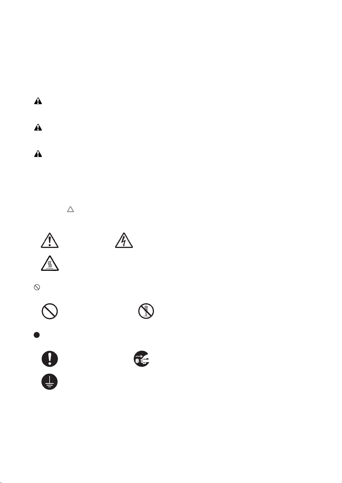
Symbols
The triangle ( ) symbol indicates a warning including danger and caution. The specific point of attention is
shown inside the symbol.
General warning. Warning of risk of electric shock.
Warning of high temperature.
indicates a prohibited action. The specific prohibition is shown inside the symbol.
General prohibited action. Disassembly prohibited.
indicates that action is required. The specific action required is shown inside the symbol.
General action required. Remove the power plug from the wall outlet.
Always ground the copier.
Page 7

1. Installation Precautions
WARNING
• Do not use a power supply with a voltage other than that specified. Avoid multiple connections to
one outlet: they may cause fire or electric shock. When using an extension cable, always check that
it is adequate for the rated current. .....................................................................................................
• Connect the ground wire to a suitable grounding point. Not grounding the copier may cause fire or
electric shock. Connecting the earth wire to an object not approved for the purpose may cause
explosion or electric shock. Never connect the ground cable to any of the following: gas pipes, lightning rods, ground cables for telephone lines and water pipes or faucets not approved by the proper
authorities. ..........................................................................................................................................
CAUTION:
• Do not place the copier on an infirm or angled surface: the copier may tip over, causing injury. .........
• Do not install the copier in a humid or dusty place. This may cause fire or electric shock. .................
• Do not install the copier near a radiator, heater, other heat source or near flammable material. This
may cause fire. ...................................................................................................................................
• Allow sufficient space around the copier to allow the ventilation grills to keep the machine as cool
as possible. Insufficient ventilation may cause heat buildup and poor copying performance. ............
• Always handle the machine by the correct locations when moving it. .................................................
• Always use anti-toppling and locking devices on copiers so equipped. Failure to do this may cause
the copier to move unexpectedly or topple, leading to injury. ..............................................................
• Avoid inhaling toner or developer excessively. Protect the eyes. If toner or developer is accidentally
ingested, drink a lot of water to dilute it in the stomach and obtain medical attention immediately.
If it gets into the eyes, rinse immediately with copious amounts of water and obtain medical atten-
tion. .....................................................................................................................................................
• Advice customers that they must always follow the safety warnings and precautions in the copier’s
instruction handbook. .........................................................................................................................
Page 8
2. Precautions for Maintenance
WARNING
• Always remove the power plug from the wall outlet before starting machine disassembly. ................
• Always follow the procedures for maintenance described in the service manual and other related
brochures. ..........................................................................................................................................
• Under no circumstances attempt to bypass or disable safety features including safety mechanisms
and protective circuits. ........................................................................................................................
• Always use parts having the correct specifications. ............................................................................
• Always use the thermostat or thermal fuse specified in the service manual or other related brochure
when replacing them. Using a piece of wire, for example, could lead to fire or other serious acci-
dent. ...................................................................................................................................................
• When the service manual or other serious brochure specifies a distance or gap for installation of a
part, always use the correct scale and measure carefully. ..................................................................
• Always check that the copier is correctly connected to an outlet with a ground connection. ...............
• Check that the power cable covering is free of damage. Check that the power plug is dust-free. If it
is dirty, clean it to remove the risk of fire or electric shock. .................................................................
• Never attempt to disassemble the optical unit in machines using lasers. Leaking laser light may
damage eyesight. ...............................................................................................................................
• Handle the charger sections with care. They are charged to high potentials and may cause electric
shock if handled improperly. ...............................................................................................................
CAUTION
• Wear safe clothing. If wearing loose clothing or accessories such as ties, make sure they are safely
secured so they will not be caught in rotating sections. ......................................................................
• Use utmost caution when working on a powered machine. Keep away from chains and belts. ..........
• Handle the fixing section with care to avoid burns as it can be extremely hot. ..................................
• Check that the fixing unit thermistor, heat and press rollers are clean. Dirt on them can cause
abnormally high temperatures. ...........................................................................................................
Page 9
• Do not remove the ozone filter, if any, from the copier except for routine replacement. ......................
• Do not pull on the AC power cord or connector wires on high-voltage components when removing
them; always hold the plug itself. ........................................................................................................
• Do not route the power cable where it may be stood on or trapped. If necessary, protect it with a
cable cover or other appropriate item. ................................................................................................
• Treat the ends of the wire carefully when installing a new charger wire to avoid electric leaks. ..........
• Remove toner completely from electronic components. .....................................................................
• Run wire harnesses carefully so that wires will not be trapped or damaged. ......................................
• After maintenance, always check that all the parts, screws, connectors and wires that were
removed, have been refitted correctly. Special attention should be paid to any forgotten connector,
trapped wire and missing screws. .......................................................................................................
• Check that all the caution labels that should be present on the machine according to the instruction
handbook are clean and not peeling. Replace with new ones if necessary. .......................................
• Handle greases and solvents with care by following the instructions below: ......................................
· Use only a small amount of solvent at a time, being careful not to spill. Wipe spills off completely.
· Ventilate the room well while using grease or solvents.
· Allow applied solvents to evaporate completely before refitting the covers or turning the power
switch on.
· Always wash hands afterwards.
• Never dispose of toner or toner bottles in fire. Toner may cause sparks when exposed directly to
fire in a furnace, etc. ...........................................................................................................................
• Should smoke be seen coming from the copier, remove the power plug from the wall outlet immedi-
ately. ...................................................................................................................................................
3. Miscellaneous
WARNING
• Never attempt to heat the drum or expose it to any organic solvents such as alcohol, other than the
specified refiner; it may generate toxic gas. ........................................................................................
Page 10

This page is intentionally left blank.
Page 11

CONTENTS
1-1 Specifications
1-1-1 Specifications ..........................................................................................................................................1-1-1
1-1-2 Parts names ............................................................................................................................................1-1-3
(1) Overall ...............................................................................................................................................1-1-3
(2) Operation panel.................................................................................................................................1-1-4
1-1-3 Machine cross section ............................................................................................................................1-1-5
1-2 Installation
1-2-1 Installation environment ..........................................................................................................................1-2-1
1-2-2 Unpacking ...............................................................................................................................................1-2-2
(1) Removing the tapes ..........................................................................................................................1-2-3
1-2-3 Installing the expanded memory (option)................................................................................................1-2-4
1-2-4 Installing the memory card (optional)......................................................................................................1-2-5
1-3 Maintenance Mode
1-3-1 Service mode ..........................................................................................................................................1-3-1
(1) Executing a service item ...................................................................................................................1-3-1
(2) Contents of service mode items ........................................................................................................1-3-2
(3) Printing an event log (EVENT LOG)................................................................................................1-3-10
1-4 Troubleshooting
1-4-1 Paper misfeed detection .........................................................................................................................1-4-1
(1) Paper misfeed indication ...................................................................................................................1-4-1
(2) Paper misfeed detection condition ....................................................................................................1-4-1
1-4-2 Self-diagnostic function ...........................................................................................................................1-4-2
(1) Self-diagnostic function .....................................................................................................................1-4-2
(2) Self diagnostic codes ........................................................................................................................1-4-3
1-4-3 Image formation problems ......................................................................................................................1-4-7
(1) Completely blank printout..................................................................................................................1-4-8
(2) All-black printout................................................................................................................................1-4-8
(3) Dropouts............................................................................................................................................1-4-9
(4) Black dots..........................................................................................................................................1-4-9
(5) Black horizontal streaks. ...................................................................................................................1-4-9
(6) Black vertical streaks.......................................................................................................................1-4-10
(7) Unsharpness. ..................................................................................................................................1-4-10
(8) Gray background.............................................................................................................................1-4-10
(9) Dirt on the top edge or back of the paper........................................................................................1-4-11
(10) Undulated printing at the right edge (scanning start position). ........................................................1-4-11
1-4-4 Electric problems ..................................................................................................................................1-4-12
1-4-5 Mechanical problems ............................................................................................................................1-4-14
2L0
1-5 Assembly and Disassembly
1-5-1 Precautions for assembly and disassembly............................................................................................1-5-1
(1) Precautions .......................................................................................................................................1-5-1
(2) Drum..................................................................................................................................................1-5-1
(3) Toner container .................................................................................................................................1-5-1
(4) How to tell a genuine Kyocera Mita toner container ..........................................................................1-5-2
1-5-2 Outer covers ...........................................................................................................................................1-5-3
(1) Detaching and refitting the top cover.................................................................................................1-5-3
(2) Detaching and refitting the right and left covers................................................................................1-5-4
1-5-3 Paper feed section ..................................................................................................................................1-5-6
(1) Detaching and refitting the paper feed roller assembly (paper feed roller and pickup roller)............1-5-6
(2) Detaching and refitting the retard roller assembly.............................................................................1-5-8
(3) Detaching and refitting the MP paper feed roller.............................................................................1-5-10
1-5-4 Developing section................................................................................................................................1-5-11
(1) Detaching and refitting the developing unit .....................................................................................1-5-11
1-5-5 Drum section .........................................................................................................................................1-5-12
(1) Detaching and refitting the drum unit ..............................................................................................1-5-12
(2) Detaching and refitting the main charger unit..................................................................................1-5-13
Page 12

2L0
1-5-6 Transfer/separation section ..................................................................................................................1-5-14
(1) Detaching and refitting the transfer roller ........................................................................................1-5-14
1-5-7 Fuser section ........................................................................................................................................1-5-16
(1) Detaching and refitting the fuser unit...............................................................................................1-5-16
(2) Switching the fuser pressure...........................................................................................................1-5-18
1-5-8 PWBs ....................................................................................................................................................1-5-19
(1) Detaching and refitting the control PWB .........................................................................................1-5-19
(2) Detaching and refitting the power source PWB...............................................................................1-5-22
(3) Detaching and refitting the high voltage PWB .................................................................................1-5-24
1-5-9 Others ...................................................................................................................................................1-5-28
(1) Detaching and refitting the main motor ...........................................................................................1-5-28
(2) Detaching and refitting the laser scanner unit.................................................................................1-5-29
(3) Detaching and refitting the eraser lamp (PWB)...............................................................................1-5-31
(4) Direction of installing the left cooling fan motor and right cooling fan motor ...................................1-5-32
1-6 Firmware
1-6-1 Downloading firmware ............................................................................................................................1-6-1
(1) Firmware files ....................................................................................................................................1-6-1
(2) Downloading the firmware from the USB memory ............................................................................1-6-2
(3) Downloading the firmware from the memory card.............................................................................1-6-4
2-1 Mechanical Construction
2-1-1 Paper feed/conveying section.................................................................................................................2-1-1
(1) Cassette paper feed section..............................................................................................................2-1-1
(2) MP tray paper feed section ...............................................................................................................2-1-2
(3) Paper conveying section ...................................................................................................................2-1-3
2-1-2 Drum section ...........................................................................................................................................2-1-4
(1) Drum section .....................................................................................................................................2-1-4
(2) Main charger unit...............................................................................................................................2-1-5
2-1-3 Optical section ........................................................................................................................................2-1-6
(1) Laser scanner unit.............................................................................................................................2-1-6
2-1-4 Developing section..................................................................................................................................2-1-8
2-1-5 Transfer/separation section ....................................................................................................................2-1-9
2-1-6 Cleaning section ...................................................................................................................................2-1-10
2-1-7 Fuser section ........................................................................................................................................2-1-11
2-1-8 Paper exit section .................................................................................................................................2-1-13
2-1-9 Duplex/conveying section .....................................................................................................................2-1-15
2-2 Electrical Parts Layout
2-2-1 Electrical parts layout ..............................................................................................................................2-2-1
(1) PWBs ................................................................................................................................................2-2-1
(2) Switches and sensors .......................................................................................................................2-2-3
(3) Other electrical components..............................................................................................................2-2-4
2-3 Operation of the PWBs
2-3-1 Power source PWB .................................................................................................................................2-3-1
2-3-2 Control PWB ...........................................................................................................................................2-3-3
2-4 Appendixes
2-4-1 Appendixes .............................................................................................................................................2-4-1
(1) Wiring diagram ..................................................................................................................................2-4-1
(2) Repetitive defects gauge...................................................................................................................2-4-2
(3) Maintenance parts list .......................................................................................................................2-4-3
Page 13

1-1 Specifications
1-1-1 Specifications
Type................................................Desktop
Printing method...............................Electrophotography, laser scan
Paper weight...................................Cassette: 60 to 120 g/m
MP tray: 60 to 220 g/m
Paper type ......................................Cassette:
Plain, Preprinted, Bond, Recycled, Rough, Letterhead, Color (Colour),
Prepunched, High quality, Custom 1 to 8
MP tray:
Plain, Transparency, Preprinted, Labels, Bond, Recycled, Rough, Vellum,
Letterhead, Color (Colour), Prepunched, Envelope, Cardstock, Thick paper,
High quality, Custom 1 to 8
Paper size.......................................Cassette:
A4, JIS B5, A5, Folio, Legal, Letter, Oficio II, Statement, Executive, A6, B6,
ISO B5, Envelope C5, 16K,
Custom (105 148 to 216 356 mm/4
MP tray:
A4, JIS B5, A5, Folio, Legal, Letter, Oficio II, Statement, Executive, A6, B6,
ISO B5, Envelope C5, Envelope #10, Envelope #9, Envelope #6Envelope Monarch, Envelope DL, Hagaki, Ofuku Hagaki, 16K, Yokei 2, Yokei 4,
Custom (70 148 to 216 356 mm/2
Printing speed.................................Simplex printing:
35 ppm (A4)
37 ppm (Letter)
17 ppm (A5)
Duplex printing
19 ppm (A4)
20 ppm (Letter)
First print time .................................7 seconds or less (A4, feed from cassette)
Warm-up time .................................120 V AC model:
Power on 20 seconds or less (22
Sleep 15 seconds or less (22
220 - 240 V AC model:
Power on 19 seconds or less (22
Sleep 14 seconds or less (22
Paper capacity ................................ Cassette: 250 sheets (80 g/m
MP tray: 50 sheets (80 g/m
Output tray capacity........................Simplex printing: 250 sheets (80 g/m2)
Duplex printing: 200 sheets (80 g/m
Continuous printing.........................1 to 999 sheets
Photoconductor...............................OPC drum (diameter 30 mm)
Image write system.........................Semiconductor laser (1 beam)
Charging system.............................Scorotron (positive charging)
Developing system .........................Mono component dry developing method
Toner replenishing: Automatic from the toner container
Transfer system .............................. Transfer roller (negative-charged)
Separation system..........................Small diameter separation, discharger brush
Cleaning system .............................Drum: Counter blade
Charge erasing system...................Exposure by eraser lamp (LED)
Fusing system................................. Heat roller system
Memory...........................................Standard: 128 MB
Maximum: 1152 MB
Resolution.......................................Fine 1200 mode, Fast 1200 mode, 600 dpi, 300 dpi
Operating environment ................... Temperature: 10 to 32.5
Humidity: 15 to 80%
Altitude: 2,500 m/8,202 ft maximum
Brightness: 1,500 lux maximum
2
(Duplex: 60 to 105 g/m2)
2
1/8 5 13/16" to 8 1/2 14")
13/16 5 13/16" to 8 1/2 14")
C/71.6 F, 60%RH)
C/71.6 F, 60%RH)
C/71.6 F, 60%RH)
C/71.6 F, 60%RH)
2
, A4/Letter or smaller)
2
, A4/Letter or smaller)
2
)
C/50 to 90.5 F
2L0-2
3/4,
1-1-1
Page 14

2L0
Controller ........................................PowerPC 440F5/500 MHz
Supported OS ................................. Microsoft Windows 2000/XP/Vista/7, Windows Server 2003/2008,
Mac OS X 10.x
Interface..........................................Hi-Speed USB: 1
Network: 1 (10BASE-T/100BASE-TX)
KUIO-W slot: 1
PDL.................................................PRESCRIBE
Dimension (W D H)...................375 393 267 mm
14 3/4 15 1/2 10 1/2"
Weight (without toner container).....12 kg/26.5 lb
Power source..................................120 V AC, 60 Hz, 8.0 A
220 to 240 V AC, 50/60 Hz, 4.2 A
Power consumption ........................120 V AC model, Standard
Maximum: 925 W
During printing: 584.0 W
During standby: 10.3 W (EcoFuser ON), 93.3 W (EcoFuser OFF)
Sleep mode: 5.5 W
120 V AC model, Full options
Maximum: 935 W
During printing: 593.1 W
During standby: 12.9 W (EcoFuser ON), 89.1 W (EcoFuser OFF)
Sleep mode: 6.8 W
220 - 240 V AC model, Standard
Maximum: 987 W
During printing: 553.9 W
During standby: 11.0 W (EcoFuser ON), 89.3 W (EcoFuser OFF)
Sleep mode: 5.5 W
220 - 240 V AC model, Full options
Maximum: 998 W
During printing: 561.9 W
During standby: 13.5 W (EcoFuser ON), 88.2 W (EcoFuser OFF)
Sleep mode: 6.9 W
Options ...........................................Expanded memory, Paper feeder 2
NOTE: These specifications are subject to change without notice.
1-1-2
Page 15
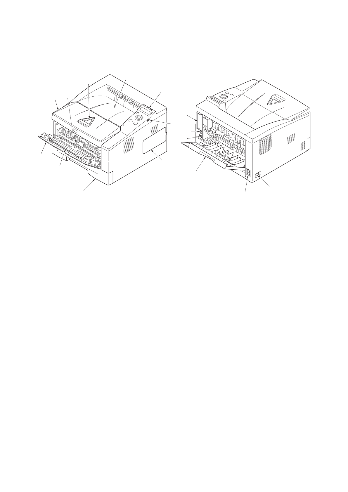
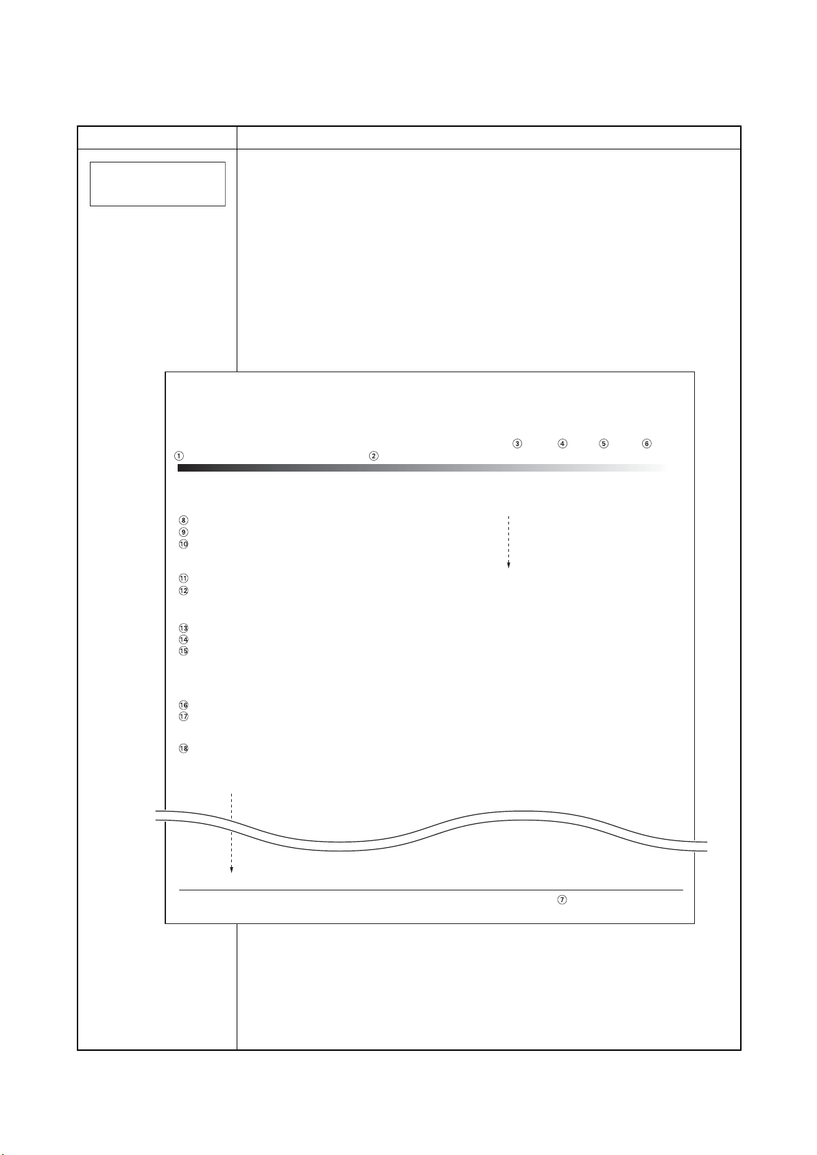
1-1-2 Parts names
2
3
4
16
1
7
9
6
10
11
12
13
14
15
8
5
1. Top cover
2. Paper stopper
3. Top tray
4. Operation panel
5. Right side cover
6. Cassette
7. Front cover
8. MP tray
9. Sub tray
10. Optional interface slot cover
11. USB interface connector
12. Network interface connector
13. Rear cover
14. Power cord connector
15. Power switch
16. USB memory slot
(1) Overall
2L0
Figure 1-1-1
1-1-3
Page 16
2L0
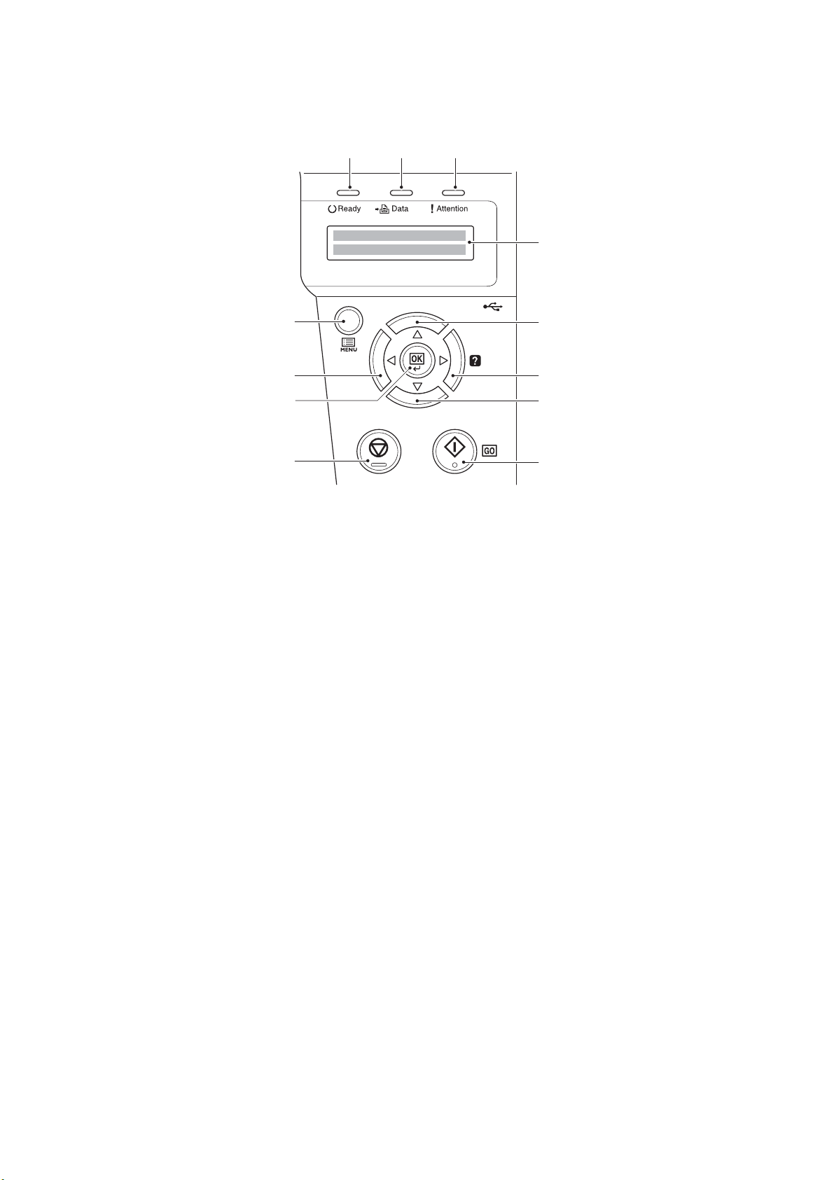
1 2 3
4
5
5
5
5
6
9
7
8
1. Ready indicator
2. Data indicator
3. Attention indicator
4. Message display
5. Cursor keys
6. GO key
7. CANCEL key
8. OK key
9. MENU key
(2) Operation panel
Figure 1-1-2
1-1-4
Page 17
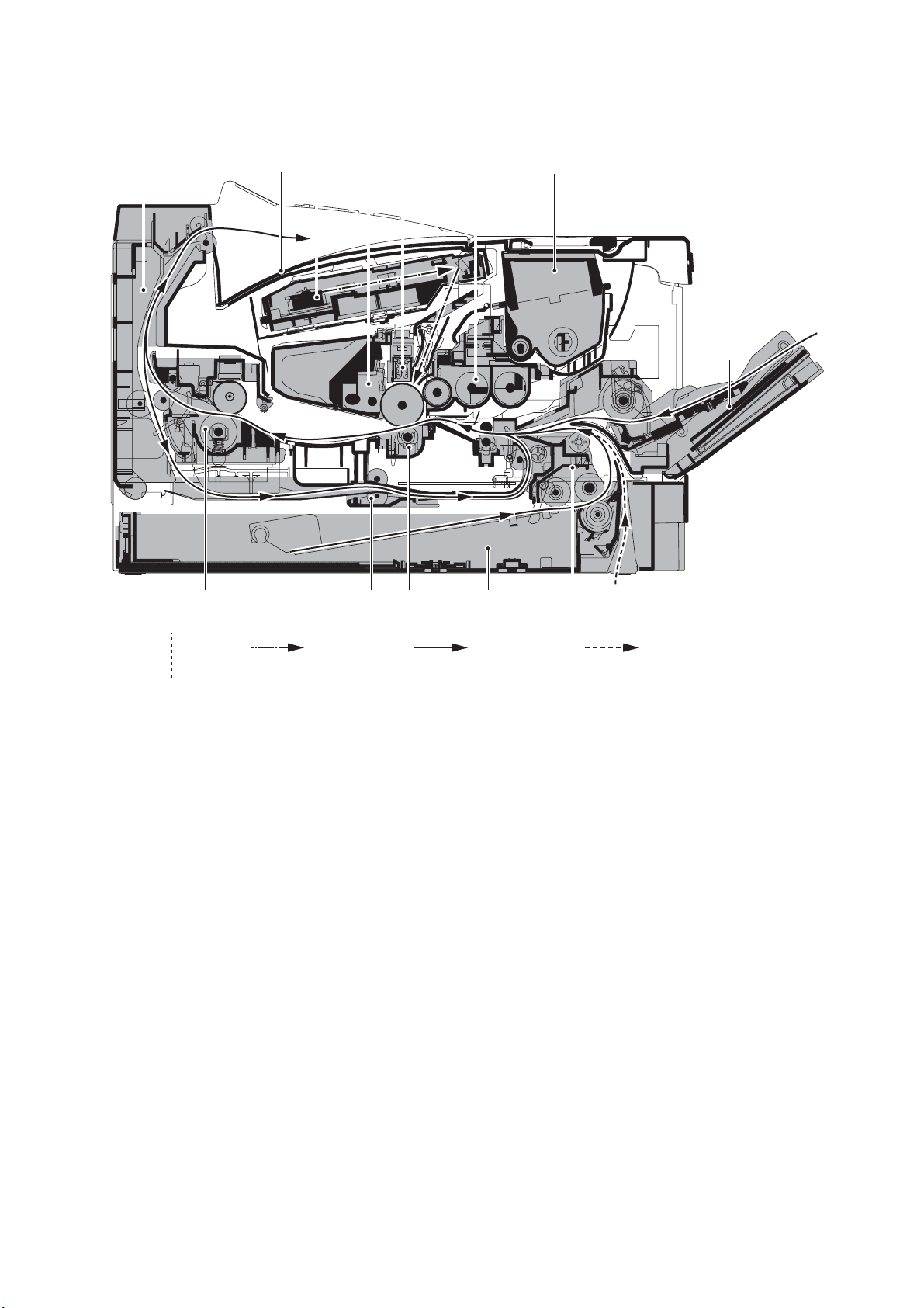
1-1-3 Machine cross section
2
13910 13
456811 12 7
Paper pathLight path Paper path
(option)
1. Cassette
2. MP tray
3. Paper feed/conveying
section
4. Toner container
5. Developing unit
6. Main charger unit
7. Drum unit
8. Laser scanner unit
9. Transfer/separation section
10. Fuser section
11. Paper exit section
12. Top tray
13. Duplex/conveying section
2L0
Figure 1-1-3
1-1-5
Page 18

2L0
This page is intentionally left blank.
1-1-6
Page 19
1-2 Installation
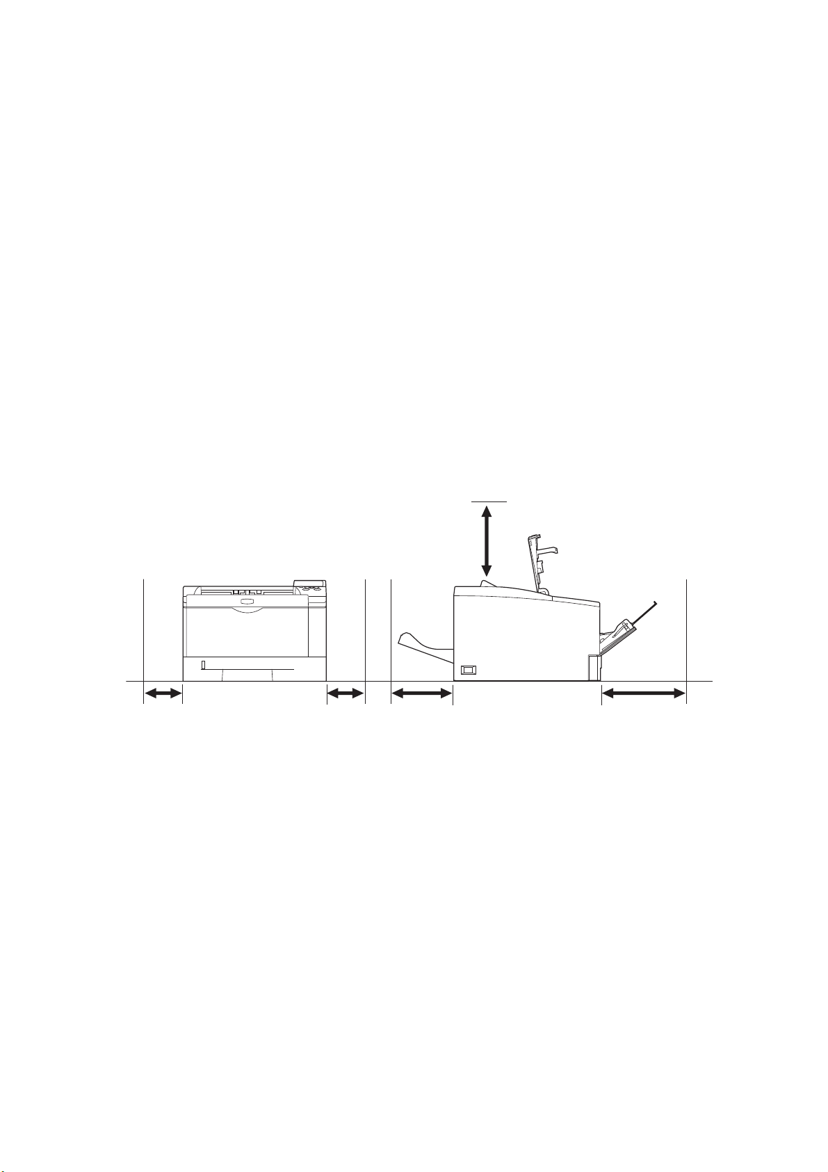
1-2-1 Installation environment
1. Temperature: 10 to 32.5C/50 to 90.5F
2. Humidity: 15 to 80%RH
3. Power supply: 120 V AC, 8.0 A
220 - 240 V AC, 4.2 A
4. Power source frequency: 50 Hz 0.3%/60 Hz 0.3%
5. Installation location
Avoid direct sunlight or bright lighting. Ensure that the photoconductor will not be exposed to direct sunlight or
other strong light when removing paper jams.
Avoid locations subject to high temperature and high humidity or low temperature and low humidity; an abrupt
change in the environmental temperature; and cool or hot, direct air.
Avoid places subject to dust and vibrations.
Choose a surface capable of supporting the weight of the machine.
Place the machine on a level surface (maximum allowance inclination: 1
Avoid air-borne substances that may adversely affect the machine or degrade the photoconductor, such as mercury, acidic of alkaline vapors, inorganic gasses, NOx, SOx gases and chlorine-based organic solvents.
Select a well-ventilated location.
6. Allow sufficient access for proper operation and maintenance of the machine.
).
2L0
Machine front: 500 mm/19
11/ 16"
Machine rear: 200 mm/7 7/8"
Machine right: 300 mm/11
13/16"
Machine left: 300 mm/11 13/16"
Machine top: 200 mm/7 7/8"
300 mm
11
13/16"
300 mm
11 13/16"
200 mm
7
200 mm
7 7/8"
Figure 1-2-1
7/8"
500 mm
19
11/16"
1-2-1
Page 20
2L0
1
2
6
8
9
7
10
13
16
15
14 14
11
3
5
4
12
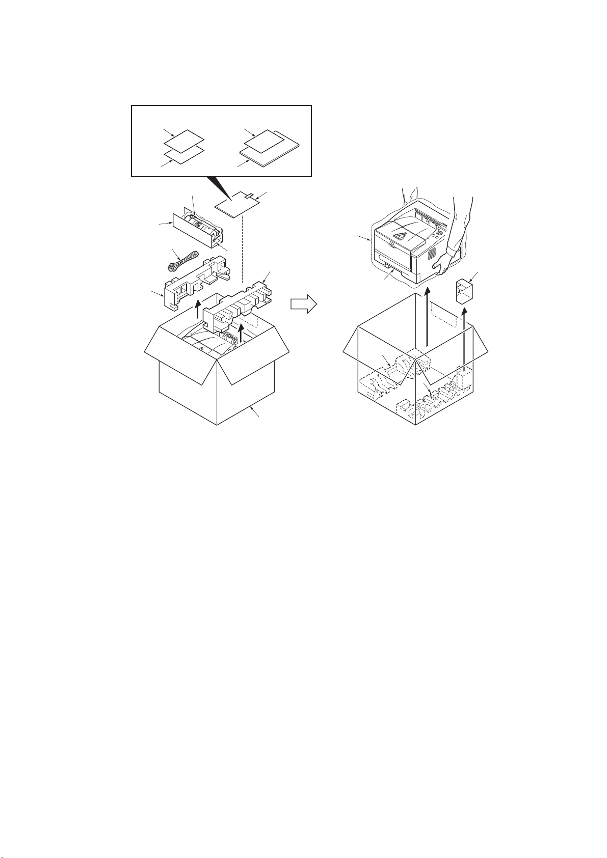
120 V AC model220 - 240 V AC model
1. Printer
2. Outer case
3. Bottom pad L
4. Bottom pad R
5. Machine cover
6. Top pad L
7. Top pad R
8. Accessory spacer
9. Toner container
10. Plastic bag
11. Power cor d
12. Rear right pad
13. Plastic bag
14. Installation guide
15. EEA information leaflet
16. Operation guide
1-2-2 Unpacking
Figure 1-2-2
1-2-2
Page 21
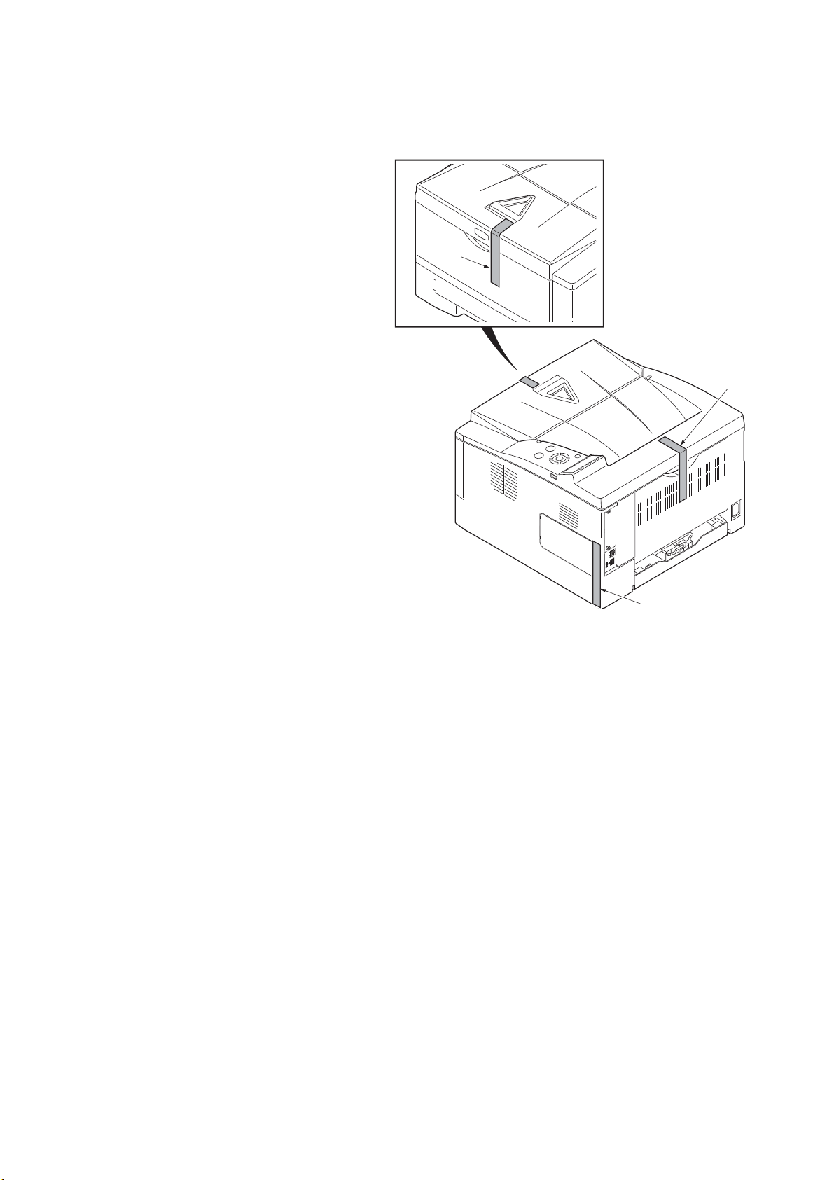
(1) Removing the tapes
Ta pe
Ta pe
Ta pe
Procedure
1. Remove three tapes.
2L0
Figure 1-2-3
1-2-3
Page 22
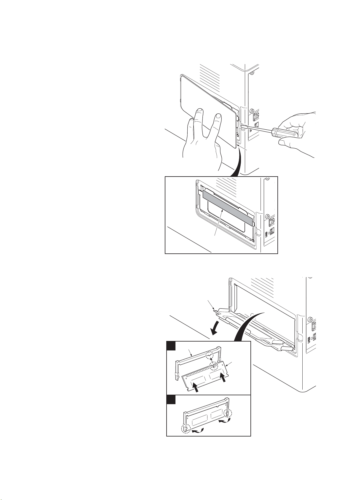
2L0
1
2
Memory slot cover
Expanded
memory
Memory socket
1-2-3 Installing the expanded memory (option)
Procedure
1. Turn off printer power switch.
Caution: Do not insert or remove expanded
memory while printer power is on.
Doing so may cause damage to the printer
and the expanded memory.
2. Remove the right side cover.
3. Remove the tape.
Right side cover
Ta pe
Figure 1-2-4
4. Open the memory slot cover.
5. Insert the expanded memory into the mem-
ory socket so that the notches on the memory align with the corresponding protrusions
in the slot.
6. Close the memory slot cover.
7. Refit the right side cover.
8. Print a status page to check the memory
expansion (See page 1-3-2).
If memory expansion has been properly performed, information on the installed memory
is printed with the total memory capacity has
been increased. Standard memory capacity
128 MB.
Figure 1-2-5
1-2-4
Page 23
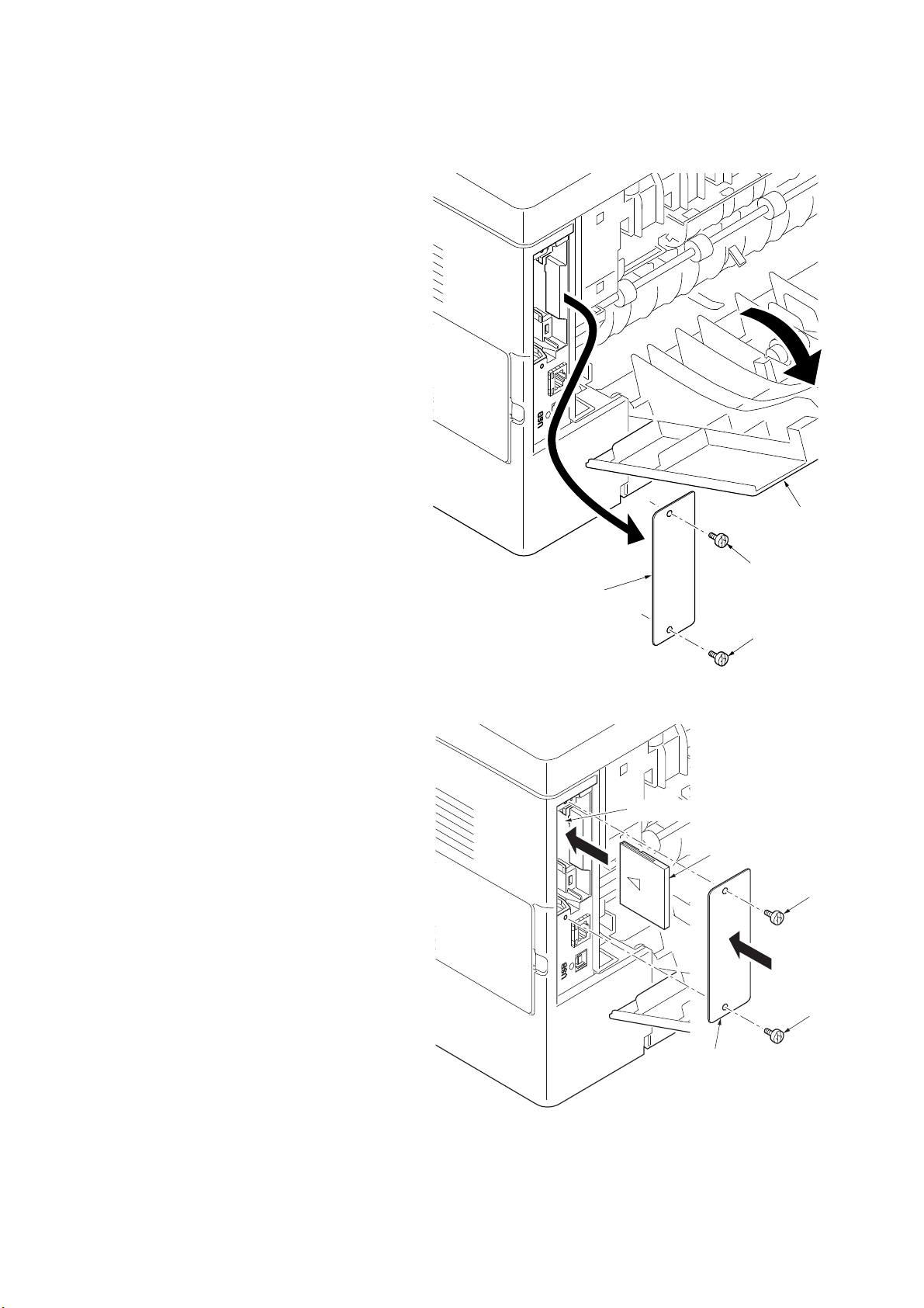
1-2-4 Installing the memory card (optional)
Optional interface
slot cover
Screw
Screw
Rear cover
Procedure
1. Turn off printer power switch.
Caution: Do not insert or remove memory
card while printer power is on.
Doing so may cause damage to the printer
and the memory card.
2. Open the rear cover.
3. Remove two screws and then remove the
optional interface slot cover.
2L0
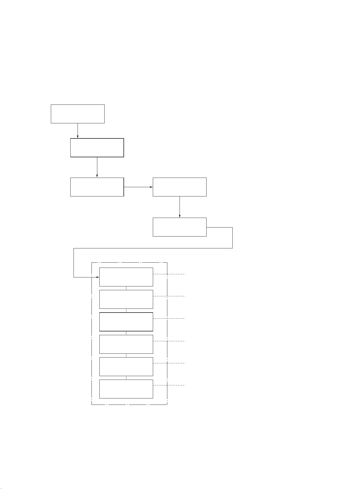
4. Insert the memory card into the memory
card slot. Push it in all the way.
5. Secure the optional interface slot cover by
using two screws.
6. Close the rear cover.
7. Format the memory card before use.
Figure 1-2-6
Memory card slot
Memory card
Screw
Screw
Optional interface
slot cover
Figure 1-2-7
1-2-5
Page 24

2L0
This page is intentionally left blank.
1-2-6
Page 25
1-3 Maintenance Mode
Ready
Report Print >
Adjust/ >
Maintenance
>Restart
Printer
>Service >
>>Print
Status Page
>>Print Network
Status Page
>>Print
Test Page
>>Write Data
>>Maintenance
>>Developer
1. Press the MENU key.
Message display
To print a status page for service purpose.
To print a network status page.
Prints a test page which contains halftone.
To write data into a USB memory.
To reset counter for the maintenance kit.
To initialize the developing unit. (toner install mode)
2. Press the or key several times
until [Adjust/Maintenance >] is displayed.
Service mode items
3. Press the key.
5. Press the key.
4. Press the or key several times
until [>Service >] is displayed.
To scroll these items,
press the or key
repeatedly.
(See page 1-3-2)
(See page 1-3-7)
(See page 1-3-7)
(See page 1-3-8)
(See page 1-3-8)
(See page 1-3-9)
1-3-1 Service mode
The printer is equipped with a service function which can be used to maintain and service the machine.
(1) Executing a service item
2L0-2
1-3-1
Page 26
2L0-1
>>Print
Status Page
Firmware version 2L0_2000.000.000
1
Standard Size
Option Slot
Total Size
Controller Information
2010.03.01 [
XXXXXXXX][XXXXXXXX][XXXXXXXX[XXXXXXXX
]
[XXXXXXXXXXXXXXXX]
500.0 KB
500.0 KB
10000.0 KB
Local Time Zone
Time Server
+01:00_Amsterdam
10.183.53.13
Default Pattern Switch
Default Font Number
FRPO parameters
B8
C5*10000+C2*100+C3000000
e-MPS error control Y6 0
Service Status Page
Printer
Memory Status
Time
Paper feeder 2
Paper feeder 3
Memory Card
Installed
Installed
Installed
Installed Options
Average(%) / Usage Page(A4/Letter Conversion)
K: 1.00 / 1111111.0 0
Last Page (%) 1.00
Toner coverage
FRPO Status
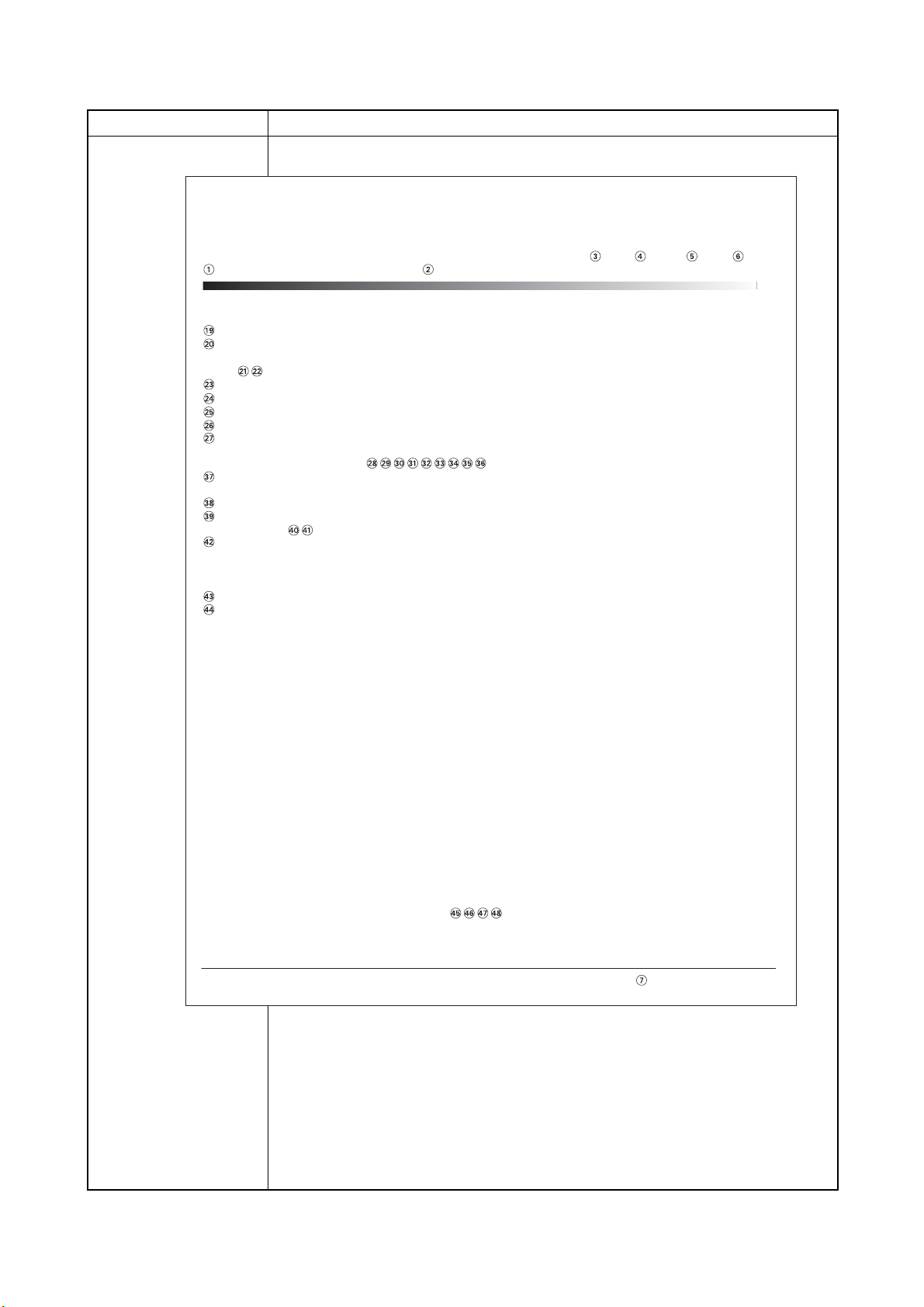
(2) Contents of service mode items
Service items Description
Printing a status page for service purpose
Description
Prints a status page for service purpose. The status page includes various printing settings and service cumulative.
Purpose
To acquire the current printing environmental parameters and cumulative information.
Procedure
1. Enter the maintenance mode [>>Print Status Page].
2. Press the OK key. [Print Status Page?] will be displayed.
3. Press the OK key. [Processing] will be displayed.
Two pages will be printed.
Completion
Figure 1-3-1Service status page 1
1-3-2
Page 27
Service items Description
No. Items Description
1 System version -
2 System date -
3 Engine software version -
4 Engine software boot version -
5 Main ROM version -
6 Operation panel mask version -
7
Machine serial number
-
8 Standard memory size -
9 Option slot memory size -
10 Total memory size -
11 Local time zone -
12 TIme server -
13 Optional paper feeder installing information Paper feeder 1
14 Optional paper feeder installing information Paper feeder 2
15 Optional memory card installing information -
16 Page of relation to the A4/Letter -
17 Coverage on the final output page -
18 FRPO setting -
Details of service status page 1
2L0
1-3-3
Page 28
2L0
1/2
100/100
0/0/0/0/0/
0/0/0/0/0/
0/0/0/0/0/0/0/0/
0000000/0000000/0000000/0000000/0000000/0000000/
0000000/
F00/U00/0/0/0/0/30/ABCDE/1/
0000/0000/0000/0000/0000/0000/0000/0000/0000/0000/0000/0000/0000/0000/0000/
0000/0000/0000/0000/0000/0000/0000/0000/0000/0000/
0203040508090A0B0C0D0F101112131415161718191A1B1C1D1E1F202122235E
12345678/11223344/00001234abcd567800001234abcd5678/01234567890123456789012345678901/0008/00/07
XXXXXXXX/t/
FFFFFFFFFFFFFFFF/FFFFFFFFFFFFFFFF/FFFFFFFFFFFFFFFF/FFFFFFFFFFFFFFFF/
FFFFFFFFFFFFFFFF/FFFFFFFFFFFFFFFF/FFFFFFFFFFFFFFFF/FFFFFFFFFFFFFFFF/
FFFFFFFFFFFFFFFF/FFFFFFFFFFFFFFFF/FFFFFFFFFFFFFFFF/FFFFFFFFFFFFFFFF/
FFFFFFFFFFFFFFFF/FFFFFFFFFFFFFFFF/FFFFFFFFFFFFFFFF/FFFFFFFFFFFFFFFF/
00/
00000000/00000000/00000000/00000000/
00000000/00000000/00000000/00000000/
00000000/00000000/00000000/00000000/
00000000/00000000/00000000/00000000/
00000000/00000000/00000000/00000000/
00000000/00000000/00000000/00000000/
00000000/00000000/00000000/00000000/
00000000/00000000/00000000/00000000/
00000000/00000000/00000000/00000000/
00000000/00000000/00000000/00000000/
00000000/00000000/00000000/00000000/
00000000/00000000/00000000/00000000/
00000000/00000000/00000000/00000000/
00000000/00000000/00000000/00000000/
00000000/00000000/00000000/00000000/
00000000/00000000/00000000/00000000/
00000000/00000000/00000000/00000000/
00000000/00000000/00000000/00000000/
00000000/00000000/00000000/00000000/
00000000/00000000/00000000/00000000/
00000000/00000000/00000000/00000000/
00000000/00000000/00000000/00000000/
00000000/00000000/00000000/00000000/
[ABCDEFGHIJ][ABCDEFGHIJ][ABCDEFGHIJ]
NVRAM Version
MAC Address
Engine Information
XXXXXXXXXXX
00.00.00.00.00.00
2
Firmware version 2L0_2000.000.000 2010.03.01 [
XXXXXXXX][XXXXXXXX][XXXXXXXX[XXXXXXXX
]
Service Status Page
Printer
[XXXXXXXXXXXXXXXX]
Service items Description
Service status page 2
Figure 1-3-2Service status page 2
1-3-4
Page 29
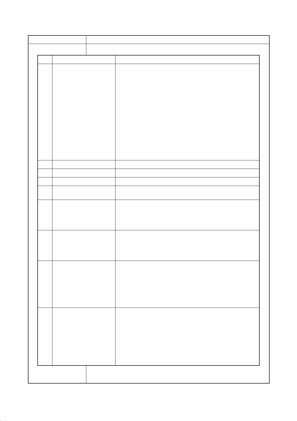
Service items Description
No. Items Description
19 NV RAM version _ Bb 04B29 _ Bb 04B29
(a) (b) (c) (d) (e) (f)
(a) Consistency of the present software version and the database
_ (underscore): OK
* (Asterisk): NG
(b) Database version
(c) The oldest time stamp of database version
(d) Consistency of the present software version and the ME firmware
version
_ (underscore): OK
* (Asterisk): NG
(e) ME firmware version
(f) The oldest time stamp of the ME database version
Normal if (a) and (d) are underscored, and (b) and (e) are identical with
(c) and (f).
20 Mac address -
21 Destination information -
22 Area information -
23 Margin settings 0/0
(a)(b)
(a) Top margin
(b) Left margin
24 Top offset for each bin 0/0/0/0/0
(a)(b)(c)(d)(e)
(a) MP tray
(b) Cassette 2
(c) Cassette 3
(d) Duplex
(e) Page rotation
25 Left offset for each bin 0/0/0/0/0
(a)(b)(c)(d)(e)
(a) MP tray
(b) Cassette 2
(c) Cassette 3
(d) Duplex
(e) Page rotation
26 L value settings 0/0/0/0/0/0/0/0
(a)(b)(c)(d)(e)(f)(g)(h)
(a) Top margin (integer)
(b) Top margin (decimal place)
(c) Left margin (integer)
(d) Left margin (decimal place)
(e) Paper length (integer)
(f) Paper length (decimal place)
(g) Paper width (integer)
(h) Paper width (decimal place)
27 Life counter 0000000/0000000/0000000/0000000/0000000/0000000/0000000/
(a) (b) (c) (d) (e) (f) (g)
(a) Printer
(b) MP tray
(c) Cassette 1
(d) Cassette 2
(e) Cassette 3
(f) Duplex printing
(g) Maintenance kit
Details of service status page 2
2L0
1-3-5
Page 30
2L0
No. Items Description
28 Operation panel lock status 0: Off
1: Partial lock
2: Full lock
29 USB information 0: Not connected
1: Full-Speed
2: Hi-Speed
30 Paper handling information 0: Paper source unit select
1: Paper source unit
31 Black and white printing dou-
ble count mode
0: All single counts
3: Folio, Single count, Less the 330 mm (length)
32 Billing counting timing -
33 Temperature (machine inside) -
34 LXI calibration information -
35 Fixed asset number -
36 Job end judgment time-out
time
-
37 Media type Weight
0: Light
1: Normal 1
2: Normal 2
3: Normal 3
4: Heavy 1
5: Heavy 2
6: Heavy 3
7: Extra Heavy
Fuser
0: Hi
1: Middle
2: Low
3: Vellum
Duplex
0: Disable
1: Enable
38 SPD information -
39 RFID information -
40 RFID reader/writer version
information
-
41 Toner install mode informa-
tion
0: OFF
1: ON
42 Engine parameter information Hexadecimal, 512 bytes
43 DRT table number -
44 DRT parameter coefficient -
45 Optional font version -
46 Optional table version -
47 Optional message version -
48 WEB optional version -
NOTE:
Code conversion
ABCDEFGH I J
0123456789
Service items Description
1-3-6
Page 31

Service items Description
FS-1350DN SN:SPL8307597 Counter:1135
2L0-1
>>Print Network
Status Page
>>Print
Test Page
Printing a status page for network
Description
On the status page for network, detailed network setting information is printed.
Procedure
1. Enter the maintenance mode [>>Print Network Status Page].
2. Press the OK key. [>>Print Network Status Page?] will be displayed.
3. Press the OK key. Three sheets of network status page will be printed.
Completion
Printing a test page
Description
Prints a test page which contains halftone.
Purpose
To check the activation of the developer and drum units.
Procedure
1. Enter the maintenance mode [>>Print Test Page].
2. Press the OK key. [>>Print Test Page?] will be displayed.
3. Press the OK key. A sheet of test page will be printed.
Completion
Figure 1-3-3
1-3-7
Page 32

2L0-2
>>Write Data
>>Maintenance
Service items Description
Write data (USB memory data write)
Description
To write data into a USB memory.
Procedure
Install the USB memory before attempting to write data.
1. Enter the maintenance mode [>>Write Data].
2. Press the OK key. [>>Write Data?] will be displayed.
3. Press the OK key. [Data waiting] is displayed and the printer waits for data to be writ-
ten.
4. When the data is sent, [Processing] appears and the data is written to USB memory.
When data writing ends, the display returns to [Ready].
Completion
Counter reset for the maintenance kit
Description
The "Install MK" message means that maintenance kit should be replaced at 100,000
pages of printing. The interval counter must be manually reset using this service item.
Maintenance kit MK-172 (for 120 V specifications)
Maintenance kit MK-170 (for 230 V specifications)
Maintenance kit MK-174 (for 240 V specifications)
Maintenance kit includes the following units:
Drum unit
Developing unit
Purpose
To reset the life counter for the developing unit and drum unit included in maintenance kit.
Procedure for replacing the maintenance kit
Drum unit (See page 1-5-12)
Developing unit (See page 1-5-11)
Procedure
1. Enter the maintenance mode [>>Maintenance].
2. Press the OK key. [>>Maintenance?] will be displayed.
3. Press the OK key twice. The counter for each component is reset immediately.
Completion
Note:
Occurrences of resetting the maintenance kits are recorded on the service status page or
event log in number of pages at which the maintenance kit was replaced (See page 1-3-2, 1-3-
10). This may be used to determine the possibility that the counter was errorneously or unintentionally reset
.
1-3-8
Page 33

Service items Description
>>Developer
Toner install mode
Description
The new developing unit is shipped from the factory with no toner contained. The developing unit can be automatically replete with toner when a toner container is installed onto it
and the printer is turned on. However, because the toner reservoir in the developing unit
has a large capacity, it requires a lengthy period of time until a substantial amount of toner
has been fed to get the printer ready. (A new developing unit needs approximately 260 g
for triggering the sensor inside.)
Purpose
To execute when the developing unit has been replaced.
Method
1. Enter the maintenance mode [>>Developer].
2. Press the OK key. [>>Developer?] will be displayed.
3. Press the OK key. [Ready] will be displayed.
4. Turn off and on the printer. [Self test] [Please wait (Adding toner)] will displayed.
The printer continually engages in this mode for a period of approximately 15
minutes, after which the printer reverts to the [Ready] state. [Ready] will displayed. Developing unit initialization is finished.
Completion
2L0
1-3-9
Page 34

2L0
(3) Printing an event log (EVENT LOG)
Service items Description
Printing an event log
(EVENT LOG)
Printing an event log (EVENT LOG)
Description
Prints a history list of occurrences of paper jam, self-diagnostics, toner replacements, etc.
Purpose
To allow machine malfunction analysis based on the frequency of paper misfeeds, self diagnostic errors and replacements.
Procedure
1. Connect the USB or network cable between printer and PC (network).
2. Connect the power cord.
Network interface
connector
Network cable
USB interface
connector
USB cable
Figure 1-3-4
3. Turn printer power on. Make sure the printer is ready.
4. Send the following PRESCRIBE command sequence from the PC to the printer.
!R!KCFG"ELOG";EXIT;
Note: To send a PRESCRIBE command sequence to the printer, use COMMAND
CENTER (the printer's embedded web) while the printer is connected to the PC via its
network interface.
A sheet of event log will be printed.
Completion
1-3-10
Page 35

Service items Description
#
16
15
14
13
12
11
10
9
8
7
6
5
4
3
2
1
Count.
9999999
8888888
7777777
6666666
5555555
4444444
3333333
2222222
1111111
999999
888888
777777
666666
555555
444444
1
Paper Jam Log
J00:
J01:
J02:
J03:
J04:
J05:
J06:
J07:
J08:
J09:
J10:
J12:
0
1
11
222
1
1
1
1
1
1
1
999
J13:
J14:
J15:
J16:
J17:
J18:
J19:
J20:
J21:
J22:
J23:
J24:
1
1
1
1
1
1
1
1
1
1
1
1
J25:
J26:
J27:
J28:
J29:
J30:
J31:
J32:
J33:
J34:
J35:
J36:
1
1
1
1
1
1
1
1
1
1
1
1
C0000:
C0001:
C0002:
C0003:
C0004:
C0005:
C0006:
C0007:
C0008:
C0009:
C0010:
C0011:
0
1
2
3
4
5
6
7
8
9
10
11
C0012:
C0013:
C0014:
C0015:
C0016:
C0017:
C0018:
C0019:
C0020:
C0021:
C0022:
C0023:
12
13
14
15
16
17
18
19
20
21
22
23
T00:
M01:1020
Counter Log
#
8
7
6
5
4
3
2
1
Count.
1111111
999999
888888
777777
666666
555555
444444
1
Service Call Log
Service Code
00. 0000
00. 0000
00. 0000
00. 0000
00. 0000
00. 0000
00. 0000
00. 0000
#
5
4
3
2
1
Count.
1111111
999999
888888
777777
666666
Unknown Toner Log
Item
00. 00
00. 00
00. 00
00. 00
00. 00
# Count.
Maintenance Log
Item
Log Data Nothing...
Event Log
Firmware Version 2L0_2000.000.000 2010.04.06 [XXXXXXXX] [XXXXXXXX] [XXXXXXXX] [XXXXXXXX]
Printer
[XXXXXXXXXXXXXXXX]
Event Descriprions
10.01.08.01.01
10.01.08.01.02
10.01.08.01.01
10.01.08.01.02
10.01.08.01.01
10.01.08.01.02
10.01.08.01.01
10.01.08.01.02
10.01.08.01.01
10.01.08.01.02
10.01.08.01.01
10.01.08.01.02
10.01.08.01.01
10.01.08.01.02
10.01.08.01.01
10.01.08.01.02
(f) (g)
(h)
10.01.08.01.01
(a) (b) (c) (d) (e)
Detail of event log
2L0-1
Figure 1-3-5 Event log
1-3-11
Page 36

2L0-1
No. Items Description
1 Firmware version -
2 Engine software ver-
sion
-
3 Engine boot version -
4 Main ROM version -
5 Panel mask version -
6 Machine serial number -
7 Paper Jam Log # Count. Event
Remembers 1 to 16 of
occurrence. If the
occurrence of the previous paper jam is less
than 16, all of the paper
jams are logged. When
the occurrence
excessed 16, the oldest occurrence is
removed.
The total page count
at the time of the
paper jam.
Log code (2 digit, hexadecimal, 5 categories)
(a) Cause of a paper jam
(b) Paper source
(c) Paper size
(d) Paper type
(e) Paper exit
Service items Description
1-3-12
Page 37

Service items Description
No. Items Description
7
cont.
(a) Cause of paper jam
10: Paper does not arrive at the registration sensor. [42] (MP tray)
10: Paper does not arrive at the registration sensor. [31] (Cassette 1)
10: Paper does not arrive at the registration sensor. [31] (Cassette 2)
10: Paper does not arrive at the registration sensor. [31] (Cassette 3)
10: Paper does not arrive at the registration sensor. [49] (Duplex conveying)
11: Paper does not pass the registration sensor. [48]
12: Paper remains at the registration sensor when power is turned on. [48]
20: Paper does not arrive at the exit sensor. [48]
21: Paper does not pass the exit sensor. [47]
22: Paper remains at the exit sensor when power is turned on. [47]
30: Paper does not arrive at the paper feeder 1’s PF paper feed sensor. [32](Cassette 2)
30: Paper does not arrive at the paper feeder 1’s PF paper feed sensor. [33] (Cassette 3)
31: Paper does not arrive at the paper feeder 1’s PF paper feed sensor. [32] (Cassette 2)
32: Paper remains at the paper feeder 1’s PF paper feed sensor when power is turned on.
[32] (Cassette 2)
40: Paper does not arrive at the paper feeder 2’s PF paper feed sensor. [33] (Cassette 3)
41: Paper does not pass the paper feeder 2’s PF paper sensor. [33] (Cassette 3)
42: Paper remains at the paper feeder 2’s PF paper feed sensor when power is turned on.
[33] (Cassette 3)
A1: Paper does not arrive at the exit sensor. [47]
A3: Paper does not pass the exit sensor. [49]
E0: Paper misfeed occurs due to forced stop when an error occurs during printing.
(such as opening of a cover) [00]
F0 to FE: Paper misfeed by another cause. [00]
Note:
Within [ ] indicate paper misfeed locations. (Refer to figure 1-3-6 below.)
Figure 1-3-6
47
48
4
49
2L0-1
Printer
Sensors
Registration
1
sensor
2
Paper sensor
3
MP paper
sensor
Exit sensor
PF paper feed sensor
PF paper sensor
31
42
4
5
6
3
2
1
Paper feeder 1
Paper feeder 2
5
6
6
32
5
33
Paper misfeed locations
31
Cassette 1 (Printer)
32
Cassette 2 (Paper feeder 1)
Cassette 3 (Paper feeder 2)
33
MP tray
42
Fuser/paper exit section
47
Printer inside
48
Duplex/conveying section
49
1-3-13
Page 38

2L0-1
No. Items Description
7
cont.
(b) Detail of paper source (Hexadecimal)
00: MP tray
01: Cassette 1 (Printer)
02: Cassette 2 (Paper feeder 1)
03: Cassette 3 (Paper feeder 2)
04 to 09: -
(c) Detail of paper size (Hexadecimal)
00: (indefinite)
01: Monarch
02: Business
03: International DL
04: International C5
05: Executive
06: Letter-R
86: Letter-E
07: Legal
08: A4R
88: A4E
09: B5R
89: B5E
0A: A3
0B: B4
0C: Ledger
0D: A5
0E: A6
0F: B6
10: Commercial #9
11: Commercial #6
12: ISO B5
13: Custom size
1E: C4
1F: Postcard
20: Reply-paid postcard
21: Oficio II
22: Special 1
23: Special 2
24: A3 wide
25: Ledger wide
26: Full bleed paper
(12 8)
27: 8K
28: 16K-R
A8: 16K-E
32: Statement-R
B2: Statement-E
33: Folio
34: Western type 2
35: Western type 4
(d) Detail of paper type (Hexadecimal)
01: Plain
02: Transparency
03: Preprint
04: Labels
05: Bond
06: Recycle
07: Vellum
08: Rough
09: Letter head
0A: Color
0B: Prepunched
0C: Envelope
0D: Cardstock
0E: Coated
0F: 2nd side
10: Media 16
11: High quality
15: Custom 1
16: Custom 2
17: Custom 3
18: Custom 4
19: Custom 5
1A: Custom 6
1B: Custom 7
1C: Custom 8
(e) Detail of paper exit location (Hexadecimal)
01: Face down tray (FU)
02 to 48: -
8 Service Call
(Self diagnostic
error) Log
# Count. Service Code
Remembers 1 to 8 of
occurrence of self diagnostics error. If the
occurrence of the previous diagnostics error is
less than 8, all of the
diagnostics errors are
logged.
The total page count at
the time of the self diagnostics error.
Self diagnostic error code
(See page 1-4-3)
Example
01.6000
01 means a self-diagnostic error; 6000 means a
self diagnostic error code.
Service items Description
1-3-14
Page 39

Service items Description
No. Items Description
9 Maintenance
Log
# Count. Item
Remembers 1 to 8 of
occurrence of replacement. If the occurrence of
the previous replacement
of toner container is less
than 8, all of the occurrences of replacement
are logged.
The total page count at the
time of the replacement of
the toner container.
Code of maintenance replacing
item (1 byte, 2 categories)
First byte (Replacing item)
01: Toner container
Second byte (Type of replacing
item)
00: Black (Fixed)
First byte (Replacing item)
02: Maintenance kit
Second byte (Type of replacing
item)
01: (Fixed)
10 Unknown Toner
Log
# Count. Item
Remembers 1 to 5 of
occurrence of unknown
toner detection.
If the occurrence of the
previous unknown toner
detection is less than 5,
all of the unknown toner
detection are logged.
The total page count at the
time of the “Toner Empty”
error with using an
unknown toner container.
Unknown toner log code
(1 byte, 2 categories)
First byte
01: Fixed (Toner container)
Second byte
00: Black (Fixed)
11 Counter Log
Comprised of
three log
counters including paper jams,
self diagnostics
errors, and
replacement of
the toner container.
(f) Jam (g) Self diagnostic error (h) Maintenance item replacing
Indicates the log counter
of paper jams depending
on location.
Refer to Paper Jam Log.
All instances including
those are not occurred
are displayed.
Indicates the log counter of
self diagnostics errors
depending on cause.
(See page 1-4-3)
Example
C6000: 4
Self diagnostics error
6000 has happened four
times.
Indicates the log counter
depending on the maintenance
item for maintenance.
T: Toner container
00: Black
Example
T00: 1
The (black) toner container has
been replaced once.
2L0-1
1-3-15
Page 40

2L0
This page is intentionally left blank.
1-3-16
Page 41

1-4 Troubleshooting
Attention indicator
Paper jam
Printer
Paper misfeed location
Paper misfeed display
r
1-4-1 Paper misfeed detection
(1) Paper misfeed indication
When a paper misfeed occurs, the printer immediately stops printing and displays the paper misfeed message on the
operation panel. To remove paper misfed in the printer, pull out the paper cassette, open the front cover, rear cover or
duplexer’s cover, or remove the drum unit.
Figure 1-4-1
(2) Paper misfeed detection condition
(1) Registration sensor
(2) Paper sensor
(3) MP paper sensor
(4) Exit sensor
(5) PF paper feed senso
(6) PF paper sensor
2L0
(4)
(1)
(6)
(6)
Figure 1-4-2
(3)
(2)
Printer
(5)
Peper feeder 1
(Option)
(5)
Peper feeder 2
(Option)
1-4-1
Page 42

2L0-1
r
r
r
1-4-2 Self-diagnostic function
(1) Self-diagnostic function
This printer is equipped with self-diagnostic function. When a problem is detected, the printer stops printing and display an
error message on the operation panel. An error message consists of a message prompting a contact to service personnel
and a four-digit error code indicating the type of the error. (The display varies depending on the type of the error.)
Attention indicato
Call service
Error code
Error code
6000
Attention indicato
Call service
F000
Attention indicato
Error code
Error.power off.
F030
Figure 1-4-3
1-4-2
Page 43

(2) Self diagnostic codes
2L0-1
Code Contents
Causes Check procedures/corrective measures
0100 Backup memory device error Defective flash
memory (U10).
Defective control
PWB.
0110 Backup memory data error Defective flash
memory (U10).
Defective control
PWB.
0120 MAC address data error Defective control
PWB.
0150 Control PWB EEPROM error
Detecting control PWB EEPROM (U300)
communication error.
0170 Billing counting error Defective control
0420 Paper feeder communication error
Communication error between control
PWB and optional paper feeder.
Improper installation control PWB
EEPROM (U300).
Defective control
PWB.
PWB.
Improper installation paper feeder.
Defective harness
between control
PWB (YC318) and
paper feeder interface connector, or
improper connector insertion.
Defective control
PWB.
Remarks
Replace the control PWB (See page 1-5-
19).
Replace the control PWB (See page 1-5-
19).
Replace the control PWB (See page 1-5-
19).
Replace the control PWB (See page 1-5-
19).
Replace the control PWB (See page 1-5-
19).
Check the installation of the EEPROM
(U300) and remedy if necessary (See page
1-5-19).
Replace the control PWB (See page 1-5-
19).
Replace the control PWB (See page 1-5-
19).
Follow installation instruction carefully again.
Reinsert the connector. Also check for continuity within the connector harness. If none,
remedy or replace the harness.
Replace the control PWB (See page 1-5-
19).
Defective harness
between PF main
PWB (YC5) and
paper feeder interface connector, or
improper connector insertion.
Defective PF main
PWB.
Reinsert the connector. Also check for continuity within the connector harness. If none,
remedy or replace the harness (Refer to the
service manual for the paper feeder).
Replace the PF main PWB (Refer to the service manual for the paper feeder).
1-4-3
Page 44

2L0
Code Contents
2000 Main motor error
The main motor ready input is not given
for 2 s during the main motor is ON.
4000 Polygon motor (laser scanner unit)
error
The polygon motor ready input is not
given for 6 s during the polygon motor is
ON.
Remarks
Causes Check procedures/corrective measures
Defective harness
between main
motor (CN1) and
control PWB
(YC305), or
improper connector insertion.
Defective drive
transmission system of the main
motor.
Defective main
motor.
Defective control
PWB.
Defective harness
between polygon
motor and control
PWB (YC319), or
improper connector insertion.
Defective laser
scanner unit.
Reinsert the connector. Also check for continuity within the connector harness. If none,
remedy or replace the harness.
Check if the rollers and gears rotate
smoothly. If not, grease the bushings and
gears. Check for broken gears and replace if
any.
Replace the main motor (See page 1-5-28).
Replace the control PWB (See page 1-5-
19).
Reinsert the connector. Also check for continuity within the connector harness. If none,
remedy or replace the harness.
Replace the laser scanner unit (See page 15-29).
Defective control
PWB.
4200 BD error (laser scanner unit) error Defective laser
scanner unit.
Defective control
PWB.
6000 Broken fuser heater lamp wire
The fuser temperature does not rise after
the fuser heater lamp has been turned
on.
6020 Abnormally high fuser thermistor
temperature
Fuser thermistor detects abnormally
temperature.
Poor contact in the
fuser thermistor
connector terminals.
Poor contact in the
fuser heater lamp
connector terminals.
Fuser thermistor
installed incorrectly.
Fuser thermal cutout triggered.
Fuser heater lamp
installed incorrectly.
Broken fuser
heater lamp wire.
Shorted fuser
thermistor.
Defective control
PWB.
Replace the control PWB (See page 1-5-
19).
Replace the laser scanner unit (See page 15-29).
Replace the control PWB (See page 1-5-
19).
Reinsert the connector (See page 1-5-16).
Reinsert the connector (See page 1-5-16).
Replace the fuser unit (See page 1-5-16).
Replace the fuser unit (See page 1-5-16).
Replace the fuser unit (See page 1-5-16).
Replace the fuser unit (See page 1-5-16).
Replace the fuser unit (See page 1-5-16).
Replace the control PWB (See page 1-5-
19).
1-4-4
Page 45

2L0
Code Contents
6030 Broken fuser thermistor wire
Input from fuser thermistor is 0 (A/D
value).
6400 Zero cross signal error
The zero cross signal does not reach the
control PWB for specified time.
Remarks
Causes Check procedures/corrective measures
Poor contact in the
fuser thermistor
connector terminals.
Broken fuser
thermistor wire.
Fuser thermistor
installed incorrectly.
Fuser thermal cutout triggered.
Fuser heater lamp
installed incorrectly.
Broken fuser
heater lamp wire.
Defective harness
between high voltage PWB (YC202)
and control PWB
(YC311), or
improper connector insertion.
Defective harness
between power
source PWB
(YC103) and high
voltage PWB
(YC201), or
improper connector insertion.
Reinsert the connector (See page 1-5-16).
Replace the fuser unit (See page 1-5-16).
Replace the fuser unit (See page 1-5-16).
Replace the fuser unit (See page 1-5-16).
Replace the fuser unit (See page 1-5-16).
Replace the fuser unit (See page 1-5-16).
Reinsert the connector. Also check for continuity within the connector harness. If none,
remedy or replace the harness.
Reinsert the connector. Also check for continuity within the connector harness. If none,
remedy or replace the harness.
Defective power
source PWB.
Defective control
PWB.
F000 Control PWB - Operation panel PWB
communication error
F010 Control PWB checksum error Defective code
Defective harness
between operation
panel PWB (YC1)
and control PWB
(YC7), or improper
connector insertion.
Defective operation panel PWB.
Defective control
PWB.
ROM (flash memory).
Defective control
PWB.
Replace the power source PWB (See page
1-5-22).
Replace the control PWB (See page 1-5-
19).
Reinsert the connector. Also check for continuity within the connector harness. If none,
remedy or replace the harness.
Replace the operation panel PWB.
Replace the control PWB (See page 1-5-
19).
Turn the power switch off/on to restart the
printer. If the error is not resolved, replace
the control PWB (See page 1-5-19).
Replace the control PWB (See page 1-5-
19).
1-4-5
Page 46

2L0
Code Contents
Causes Check procedures/corrective measures
F020 Control PWB RAM checksum error Defective main
memory (RAM) on
the control PWB.
Defective
expanded memory
(DIMM).
F030 Control PWB general failure Defective control
PWB.
F040 Control PWB engine communication
error
F050 Control PWB engine checksum error Some error may
Defective control
PWB.
have occurred
when downloading
the firmware of the
control PWB.
Defective control
PWB.
Remarks
Turn the power switch off/on to restart the
printer. If the error is not resolved, replace
control PWB (See page 1-5-19).
Replace the expanded memory (DIMM)
(See page 1-2-4).
Turn the power switch off/on to restart the
printer. If the error is not resolved, replace
control PWB (See page 1-5-19).
Turn the power switch off/on to restart the
printer. If the error is not resolved, replace
control PWB (See page 1-5-19).
Download the firmware of the control PWB
again using the memory card (See page 16-4).
Turn the power switch off/on to restart the
printer. If the error is not resolved, replace
control PWB (See page 1-5-19).
F186 Control PWB video data control error Defective control
PWB.
Turn the power switch off/on to restart the
printer. If the error is not resolved, replace
control PWB (See page 1-5-19).
1-4-6
Page 47

1-4-3 Image formation problems
ABC
123
ABC
123
ABC
123
ABC
123
ABC
123
ABC
123
This vertical
line should
be straight.
2L0
(1) Completely blank
printout.
See page 1-4-8 See page 1-4-8 See page 1-4-9 See page 1-4-9 See page 1-4-9
(6) Black vertical
streaks.
(2) All-black printout. (3) Dropouts. (4) Black dots. (5) Black horizontal
streaks.
(7) Unsharpness. (8) Gray background. (9) Dirt on the top
edge or back of
the paper.
(10)Undulated print-
ing at the right
edge (scanning
start position).
See page 1-4-10 See page 1-4-10 See page 1-4-10 See page 1-4-11 See page 1-4-11
1-4-7
Page 48

2L0
(1) Completely blank printout.
Print example Causes Check procedures/corrective measures
Defective drum unit or developing
unit.
Defective transfer bias output or
developing bias output.
Poor contact of developing bias terminal (spring) and high voltage output
terminal B (J401, J402, J403) on the
high voltage PWB.
Poor contact of transfer bias terminal
(spring) and transfer bias terminal T
(J201, J202, J203) on the high voltage PWB.
Defective laser scanner unit. Replace the laser scanner unit (See page 1-5-29).
Defective control PWB. Replace the control PWB (See page 1-5-19).
(2) All-black printout.
Print example Causes Check procedures/corrective measures
Defective main charger unit. Open the top cover and check that the drum unit and develop-
Poor contact of main charger terminal
(spring) and main charger output terminal M on the high voltage PWB.
Defective main charging output. Replace the high voltage PWB (See page 1-5-24).
Broken main charger wire. Replace the main charger unit (See page 1-5-13).
Open the top cover and check that the drum unit and developing unit are correctly seated. Investigate that the terminals
between the main charger unit and the drum unit are not in
loose contact (See page 1-5-12 and 1-5-11).
Replace the high voltage PWB (See page 1-5-24).
Check the high voltage PWB visually and correct or replace if
necessary (See page 1-5-24).
ing unit are correctly seated (See page 1-5-12).
Investigate that the terminals between the main charger unit
and the drum unit are not in loose contact.
Check the high voltage PWB visually and correct or replace if
necessary (See page 1-5-24).
1-4-8
Defective control PWB. Replace the control PWB (See page 1-5-19).
Page 49

(3) Dropouts.
ABC
123
ABC
123
ABC
123
Print example Causes Check procedures/corrective measures
2L0
(4) Black dots.
Defective developing roller (developing unit).
Defective drum unit. If the defects occur at regular intervals of 94 mm/3
Defective fuser unit (heat roller or
press roller).
Defective paper specifications. Paper with rugged surface or dump tends to cause dropouts.
Defective transfer roller installation. The transfer roller must be supported by the bushes at the
Defective transfer bias output. Replace the high voltage PWB or control PWB (See page 1-5-
If the defects occur at regular intervals of 62.8 mm/2
page 2-4-2), the problem may be the damaged developing
roller (in the developing unit). Replace the developing unit
(See page 1-5-11).
page 2-4-2), the problem may be the damaged drum (in the
drum unit). Replace the drum unit (See page 1-5-12).
If the defects occur at regular intervals of 73.162 mm/2
78.5 mm/3 1/16" (See page 2-4-2), the problem may be the
damaged heat roller or press roller (in the fuser unit). Replace
fuser unit (See page 1-5-16).
Replace paper with the one that satisfies the paper specifications.
both ends. Clean the bush to remove oil and debris. Replace
the transfer roller if necessary (See page 1-5-14).
24 or 1-5-19).
1/2" (See
11/ 16" (See
7/8", or
Print example Causes Check procedures/corrective measures
Defective drum unit or developing
unit.
(5) Black horizontal streaks.
Print example Causes Check procedures/corrective measures
Defective drum unit's ground. Check that the drum shaft and the grounding tab (printer) are
Defective drum unit. Replace the drum unit (See page 1-5-12).
If the defects occur at regular intervals of 94 mm/3
page 2-4-2), the problem may be the damaged drum (in the
drum unit). Replace drum unit (See page 1-5-12).
If the defects occur at random intervals, the toner may be leaking from the developing unit or drum unit. Replace the developing unit or drum unit (See page 1-5-11 or 1-5-12).
in good contact. Apply the grounding tab a small amount of
electroconductive grease as required.
11/ 16" (See
1-4-9
Page 50

2L0
ABC
123
ABC
123
(6) Black vertical streaks.
Print example Causes Check procedures/corrective measures
Adhesion of oxide to main charger
wire.
Defective drum unit. A streak of toner remaining on drum after printing means that
Defective developing roller (developing unit).
(7) Unsharpness.
Print example Causes Check procedures/corrective measures
Defective paper specifications. Replace paper with the one that satisfies the paper specifica-
Defective transfer roller installation. The transfer roller must be supported by the bushes at the
Defective transfer bias output. Replace the high voltage PWB or control PWB (See page 1-5-
EcoPrint mode setting. The EcoPrint mode can provides faint, unsharp printing
Remove the drum unit (See page 1-5-12). Slide the charger
cleaner (green) left and right 2 or 3 times to clean the charger
wire, then return it to its original position (CLEANER HOME
POSITION). Refer to the operation guide.
the cleaning blade (in the drum unit) is not working properly.
Replace the drum unit (See page 1-5-12).
Replace the developing unit (See page 1-5-11).
tion.
both ends. Clean the bush to remove oil and debris. Replace
the transfer roller if necessary (See page 1-5-14).
24 or 1-5-19).
because it acts to conserve toner for draft printing purpose.
For normal printing, turn the EcoPrint mode off by using the
operator panel. For details, refer to the operation guide.
(8) Gray background.
Print example Causes Check procedures/corrective measures
Print density setting. The print density may be set too high. Try adjusting the print
density. For details, refer to the operation guide.
Defective potential on the drum surface.
Defective main charger grid. Clean the main charger grid (See page 1-5-13).
Defective developing roller (developing unit).
Replace the drum unit (See page 1-5-12).
If a developing unit which is known to work normally is available for check, replace the current developing unit in the
printer with the normal one. If the symptom disappears,
replace the developing unit with a new one (See page 1-5-11).
1-4-10
Page 51

(9) Dirt on the top edge or back of the paper.
ABC
123
This vertical
line should
be straight.
Print example Causes Check procedures/corrective measures
Toner contamination in various parts. Dirty edges and back of the paper can be caused by toner
accumulated on such parts as the paper chute guide, paper
conveying paths, the bottom of the drum and developing unit,
and the fuser unit inlet. Clean these areas and parts to remove
toner.
Defective transfer roller. If the transfer roller is contaminated with toner, clean the trans-
fer roller using a vacuum cleaner or by continuously printing a
low density page until the symptom has faded away.
(10) Undulated printing at the right edge (scanning start position).
Print example Causes Check procedures/corrective measures
2L0
Defective polygon motor (laser scanner unit).
Defective control PWB. Replace the control PWB (See page 1-5-19).
Replace the laser scanner unit (See page 1-5-29).
1-4-11
Page 52

2L0
1-4-4 Electric problems
Problem Causes Check procedures/corrective measures
(1)
The machine does
not operate when the
power switch is
turned on.
No electricity at the power
outlet.
The power cord is not
plugged in properly.
The top cover is not closed
completely.
Broken power cord. Check for continuity. If none, replace the cord.
Defective power switch. Check for continuity across the contacts. If none, replace the
Blown fuse in the power
source PWB.
Defective interlock switch. Check for continuity across the contacts of interlock switch. If
Measure the input voltage.
Check the contact between the power plug and the outlet.
Check the top cover.
power source PWB (See page 1-5-22).
Check for continuity. If none, remove the cause of blowing and
replace the power source PWB (See page 1-5-22).
none, replace the power source PWB (See page 1-5-22).
(2)
Right cooling fan
motor does not operate.
(3)
Left cooling fan
motor does not operate.
(4)
Registration clutch
does not operate.
Defective power source
PWB.
Defective control PWB. Replace the control PWB (See page 1-5-19).
Broken right cooling fan
motor coil.
Defective harness between
right cooling fan motor and
control PWB (YC315), or
improper connector insertion.
Defective control PWB. Replace the control PWB (See page 1-5-19).
Broken left cooling fan
motor coil.
Defective harness between
left cooling fan motor and
control PWB (YC104), or
improper connector insertion.
Defective control PWB. Replace the control PWB (See page 1-5-19).
Broken registration clutch
coil.
Defective harness between
registration clutch and control PWB (YC308), or
improper connector insertion.
Replace the power source PWB (See page 1-5-22).
Check for continuity across the coil. If none, replace the right cooling fan motor.
Reinsert the connector. Also check for continuity within the connector harness. If none, remedy or replace the harness.
Check for continuity across the coil. If none, replace the left cooling fan motor.
Reinsert the connector. Also check for continuity within the connector harness. If none, remedy or replace the harness.
Check for continuity across the coil. If none, replace the registration clutch.
Reinsert the connector. Also check for continuity within the connector harness. If none, remedy or replace the harness.
(5)
Paper feed clutch
does not operate.
1-4-12
Defective control PWB. Replace the control PWB (See page 1-5-19).
Broken paper feed clutch
coil.
Defective harness between
paper feed clutch and control PWB (YC308), or
improper connector insertion.
Defective control PWB. Replace the control PWB (See page 1-5-19).
Check for continuity across the coil. If none, replace the paper
feed clutch.
Reinsert the connector. Also check for continuity within the connector harness. If none, remedy or replace the harness.
Page 53

Problem Causes Check procedures/corrective measures
2L0
(6)
Developing clutch
does not operate.
(7)
MP paper feed solenoid does not operate.
(8)
Duplex solenoid does
not operate.
Broken developing clutch
coil.
Defective harness between
developing clutch and control PWB (YC308), or
improper connector insertion.
Defective control PWB. Replace the control PWB (See page 1-5-19).
Broken MP paper feed solenoid coil.
Defective harness between
MP paper feed solenoid
and control PWB (YC309),
or improper connector
insertion.
Defective control PWB. Replace the control PWB (See page 1-5-19).
Broken duplex solenoid
coil.
Defective harness between
duplex solenoid and control
PWB (YC317), or improper
connector insertion.
Defective control PWB. Replace the control PWB (See page 1-5-19).
Check for continuity across the coil. If none, replace the developing clutch.
Reinsert the connector. Also check for continuity within the connector harness. If none, remedy or replace the harness.
Check for continuity across the coil. If none, replace the MP paper
feed solenoid.
Reinsert the connector. Also check for continuity within the connector harness. If none, remedy or replace the harness.
Check for continuity across the coil. If none, replace the duplex
solenoid.
Reinsert the connector. Also check for continuity within the connector harness. If none, remedy or replace the harness.
(9)
Eraser lamp does not
turn on.
(10)
Paper indicator is
flashing when paper
is present in the cassette.
(11)
A paper jam in the
paper feed/conveying section or fuser
section is indicated
when the power
switch is turned on.
(12)
Attention indicator is
lit when the top cover
is closed.
Defective harness between
eraser lamp (YC701) and
control PWB (YC316), or
improper connector insertion.
Defective eraser lamp
(PWB).
Defective control PWB. Replace the control PWB (See page 1-5-19).
Defective paper sensor. Replace the paper sensor.
Defective harness between
paper sensor and control
PWB (YC306), or improper
connector insertion.
A piece of paper torn from
paper is caught around registration sensor or exit sensor.
Defective registration sensor on the high voltage
PWB.
Defective exit sensor. Replace the exit sensor.
Defective interlock switch
on the power source PWB.
Reinsert the connector. Also check for continuity within the connector harness. If none, remedy or replace the harness.
Replace the eraser lamp (PWB) (See page 1-5-31).
Reinsert the connector. Also check for continuity within the connector harness. If none, remedy or replace the harness.
Check and remove if any.
Replace the high voltage PWB (See page 1-5-24).
Check for continuity across the interlock switch. If there is no continuity when the interlock switch is on, replace the power source
PWB (See page 1-5-22).
1-4-13
Page 54

2L0
1-4-5 Mechanical problems
Problem Causes/check procedures Corrective measures
(1)
No primary paper feed.
(2)
No secondary paper
feed.
Check if the surfaces of the paper feed roller
is dirty with paper powder.
Check if the paper feed roller is deformed. Check visually and replace any deformed
Defective paper feed clutch installation. Check visually and remedy if necessary.
Check if the surfaces of the upper and lower
registration rollers are dirty with paper powder.
Defective registration clutch installation. Check visually and remedy if necessary.
Clean with isopropyl alcohol.
paper feed roller (assembly) (See page 1-5-
6).
Clean with isopropyl alcohol.
(3)
Skewed paper feed.
(4)
Multiple sheets of paper
are fed at one time.
(5)
Paper jams.
(6)
Toner drops on the paper
conveying path.
(7)
Abnormal noise is heard.
Paper width guide in a cassette installed
incorrectly.
Check if the separator pad or MPF separation
pad is worn.
Check if the paper is curled. Replace the paper.
Check if the paper is excessively curled. Replace the paper.
Check if the contact between the upper and
lower registration rollers is correct.
Check if the heat roller or press roller is
extremely dirty or deformed.
Check if the contact between the ejection
roller and fuser ejection pulley is correct.
Check if the drum unit or developing unit is
extremely dirty.
Check if the pulleys, rollers and gears operate
smoothly.
Check if the following electromagnetic
clutches are installed correctly:
Paper feed clutch, registration clutch and
developing clutch.
Check the paper width guide visually and
correct or replace if necessary.
Replace the separator pad if it is worn.
Check visually and remedy if necessary.
Replace the fuser unit (See page 1-5-16).
Check visually and remedy if necessary.
Clean the drum unit or developing unit (See
page 1-5-11 or 1-5-12).
Grease the bearings and gears.
Check visually and remedy if necessary.
1-4-14
Page 55

2L0
1-5 Assembly and Disass embly
1-5-1 Precautions for assembly and disassembly
(1) Precautions
Be sure to turn the power switch off and disconnect the power plug before starting disassembly.
When handling PWBs, do not touch connectors with bare hands or damage the PWB.
Do not touch any PWB containing ICs with bare hands or any object prone to static charge.
When removing the hook of the connector, be sure to release the hook.
Take care not to get the wire caught.
To reassemble the parts, use the original screws. If the types and the sizes of screws are not known, refer to the PARTS
LIST.
(2) Drum
Note the following when handling or storing the drum.
When removing the drum unit, never expose the drum surface to strong direct light.
Keep the drum at an ambient temperature between 0
90% RH. Avoid abrupt changes in temperature and humidity.
Avoid exposure to any substance which is harmful to or may affect the quality of the drum.
Do not touch the drum surface with any object. Should it be touched by hands or stained with oil, clean it.
°C/32 °F and 40 °C/104 °F and at a relative humidity not higher than
(3) Toner container
Store the toner container in a cool, dark place.
Avoid direct light and high humidity.
1-5-1
Page 56

2L0
Incision
Cut
(4) How to tell a genuine Kyocera Mita toner container
As a means of brand protection, the Kyocera Mita toner container utilizes an optical security technology to enable visual
validation. A validation viewer is required to accomplish this.
Hold the validation viewer over the left side part of the brand protection seal on the toner container. Through each window
of the validation viewer, the left side part of the seal should be seen as follows:
A black-colored band when seen through the left side window
A shiny or gold-colored band when seen through the right side window
The above will reveal that the toner container is a genuine Kyocera Mita branded toner container, otherwise, it is a counterfeit.
See through the left window
( marking)
Brand
protection
seal
A black-colored band when
seen through the left side window
See through the right window
( marking)
Validation viewerValidation viewer
Brand
protection
seal
A shiny or gold-colored band when
seen through the right side window
Figure 1-5-1
The brand protection seal has an incision as shown below to prohibit reuse.
Figure 1-5-2
1-5-2
Page 57

1-5-2 Outer covers
Top cover
Screw
Screw
Top cover
Top cover
Connector
Boss
B hook
B hook
A hook
Hole
(1) Detaching and refitting the top cover
Procedure
1. Open the top cover.
2. Remove two screws.
2L0
Figure 1-5-3
3. Extract the boss from the hole.
4. Unhook the A hook.
5. Unhook two B hooks.
6. Remove the connector.
7. Remove the top cover.
Figure 1-5-4
1-5-3
Page 58

2L0
Right cover
Hooks
(2) Detaching and refitting the right and left covers
Procedure
1. Remove the top cover (See page 1-5-3).
2. Remove the cassette (See page 1-5-6).
3. Open the front cover.
4. Unhook seven hooks and then remove the
right cover.
Figure 1-5-5
1-5-4
Page 59

5. Unhook seven hooks and then remove the
Left cover
Hooks
left cover.
2L0
Figure 1-5-6
1-5-5
Page 60

2L0
Cassette
1-5-3 Paper feed section
(1) Detaching and refitting the paper feed roller assembly (paper feed roller and pickup roller)
Procedure
1. Remove the cassette.
2. Slide the feed shaft.
3. While pressing the lever and then remove
the paper feed roller assembly.
Figure 1-5-7
Feed shaft
1-5-6
Paper feed roller
assembly
Lever
Figure 1-5-8
Page 61

2L0
4. Check or replace the paper feed roller
assembly and refit all the removed parts.
When refitting the paper feed roller assembly, be sure to align the paper feed roller
pivot with the slotted hole on the feed shaft.
Paper feed roller
assembly
Pivot
Feed shaft
Paper feed roller
assembly
Feed shaft
Slotted hole
Figure 1-5-9
1-5-7
Page 62

2L0
Retard guide
Cassestte
Cassette
Hook
Hook
Hook
Hook
Bottom plate
Retard roller
Assembly
(2) Detaching and refitting the retard roller assembly
Procedure
1. Remove the cassette (See page 1-5-6).
2. Push the bottom plate down until it locks.
3. Unhook two hooks and then remove the
retard guide.
4. Remove the retard roller assembly.
Figure 1-5-10
Figure 1-5-11
1-5-8
Page 63

5. Check or replace the retard roller assembly
Spring
Retard roller
assembly
Projection
and refit all the removed parts.
Caution: Before refitting the retard roller
assembly, firmly install the spring onto the
projection of the retard roller assembly.
2L0
Figure 1-5-12
1-5-9
Page 64

2L0
MP feed holder
(Lever)
Front cover
MP paper feed roller
MP paper feed roller
MPF feed shaft
Pivot
MP paper feed roller
Slotted hole
(3) Detaching and refitting the MP paper feed roller
Procedure
1. Open the front cover.
2. Pull the MP feed holder (lever) down (1).
3. Slide the MP feed holder (2).
4. Remove the MP paper feed roller (3).
5. Check or replace the MP paper feed roller
and refit all the removed parts.
When refitting the MP paper feed roller, be
sure to align the MPF feed shaft pivot with
the slotted hole on the MP paper feed roller.
Figure 1-5-13
Figure 1-5-14
1-5-10
Page 65

1-5-4 Developing section
Developing unit
Front cover
Top cover
(1) Detaching and refitting the developing unit
Procedure
1. Open the top cover.
2. Open the front cover.
3. Remove the developing unit (with toner container).
4. Check or replace the developing unit and
refit all the removed parts.
5. When the developing unit is replaced with a
new one, carry out the following procedure.
6. Perform toner install mode in the service
mode (see page 1-3-9).
2L0
Figure 1-5-15
1-5-11
Page 66

2L0
Drum unit
1-5-5 Drum section
(1) Detaching and refitting the drum unit
Procedure
1. Remove the developing unit (See page 1-5-
11) .
2. Remove the drum unit.
3. Check or replace the drum unit and refit all
the removed parts.
Figure 1-5-16
1-5-12
Page 67

(2) Detaching and refitting the main charger unit
Main charger unit
Procedure
1. Remove the drum unit (See page 1-5-12).
2. Remove the tape.
3. While pushing on the main plate (1), slide
the main charger unit (2).
2L0
Ta pe
Main charger unit
Drum unit
Main charger unit
4. Remove the main charger unit by lifting it.
5. Check or replace the main charger unit and
refit all the removed parts.
Main plate
Figure 1-5-17
Figure 1-5-18
1-5-13
Page 68

2L0
Hook
Hook
Hook
Hook
Paper chute guide
Paper chute guide
1-5-6 Transfer/separation section
(1) Detaching and refitting the transfer roller
Procedure
1. Remove the developing unit (See page 1-5-
11) .
2. Remove the drum unit (See page 1-5-12).
3. Slide the paper chute guide and unhook the
hooks.
4. Remove the paper chute guide.
Figure 1-5-19
1-5-14
Page 69

2L0
5. Remove the transfer roller’s shaft from the
both transfer bushes.
6. Remove the gear Z16 from the transfer
roller.
Shaft
Transfer roller
Shaft
Transfer bush
Transfer bush
Transfer roller
Gear Z16
7. Check or replace the transfer roller and refit
all the removed parts.
Caution: When refitting the transfer roller, be
careful about following point.
Push the release lever to raise the lever
end, then insert the front of gear Z16 under
the release lever end.
Figure 1-5-20
Gear Z16
Release lever
Transfer bush
Transfer roller
Transfer bush
Figure 1-5-21
1-5-15
Page 70

2L0
Connector
1-5-7 Fuser section
(1) Detaching and refitting the fuser unit
Procedure
1. Remove the outer covers (See page 1-5-3).
2. Remove two connectors.
3. Release the wires form wire clamps.
Wires
Wire clamps
Connector
(Fuser heater lamp)
Connector
(Fuser thermistor)
4. Remove the connector.
Figure 1-5-22
1-5-16
Figure 1-5-23
Page 71

5. Open the rear cover and then remove the
Rear cover
rear cover.
2L0
6. Remove two screws and then remove the
fuser unit.
7. Check or replace the fuser unit and refit all
the removed parts.
Figure 1-5-24
Fuser unit
Screw
Screw
Figure 1-5-25
1-5-17
Page 72

Fuser lever R
Duplex cover
Fuser lever L
Fuser lever L (R)
Fuser lever L (R)
Normal
Fuser pressure
decreased
2L0
(2) Switching the fuser pressure
The fuser pressure may be decreased to suppress the print quality problems such as paper creases and curls.
It must be cautioned that decreasing the fuser pressure could cause loose toner fusing.
Procedure
1. Remove the cassette (See page 1-5-6).
2. Open the duplex cover.
3. Slide the fuser lever R and L.
Normal:
Flush with the front of the machine.
Fuser pressure decreased:
Flush with the rear of the machine.
Figure 1-5-26
1-5-18
Page 73

1-5-8 PWBs
Connectors
(Thirteen)
Connector
Control PWB
Control PWB
Wire clamps
(1) Detaching and refitting the control PWB
Procedure
1. Remove the right cover (See page 1-5-4).
2. Remove the fourteen connectors form the
control PWB.
3. Release the wires from the wire clamps.
2L0
Figure 1-5-27
1-5-19
Page 74

2L0
Hook
Screws
Control PWB assembly
Control PWB
Screw
Screws
Connectors
(Four)
4. Remove five screws.
5. Remove the four connectors form the control PWB.
6. Unhook the hook and then remove the control PWB assembly.
Figure 1-5-28
1-5-20
Page 75

7. Remove five screws and then remove the
Screw
Screw
Screw
Screw
Screw
Control PWB
Control PWB
U300
EEPROM
control PWB.
8. Check or replace the control PWB and refit
all the removed parts.
To replace the control PWB, remove the
EEPROM (U300) from the old control PWB
and mount it to the new control PWB.
2L0
Figure 1-5-29
1-5-21
Page 76

2L0
Connector
Connector
Connector
Connector
Power source
PWB assembly
P tight screws
P tight screws
Ground
terminal
Screws
Connector
(YC201)
High voltage PWB
Connector
(YC103)
(2) Detaching and refitting the power source PWB
Procedure
1. Remove the left cover (See page 1-5-4).
2. Remove four connectors.
Figure 1-5-30
3. Remove four P tight screws, two screws and
ground terminal.
4. Remove the power source PWB assembly
from the high voltage PWB’s connector.
1-5-22
Figure 1-5-31
Page 77

5. Remove four screws and then remove the
Power source PWB
Screws
Screws
Power source plate
Power source film
power source plate from the power source
PWB.
6. Check or replace the power source PWB
and refit all the removed parts.
Caution: The power source film must be
installed in the specified position.
2L0
Figure 1-5-32
1-5-23
Page 78

2L0
Stop ring
DU holder
(3) Detaching and refitting the high voltage PWB
Procedure
1. Remove the developing unit (See page 1-5-
11) .
2. Remove the drum unit (See page 1-5-12).
3. Remove the cassette (See page 1-5-6).
4. Remove the outer covers (See page 1-5-3).
5. Remove the power source PWB (See page
1-5-22).
6. Turn the printer with the bottom side up.
7. Remove the stop ring.
8. Remove the DU holder.
9. Pull out the DU bush.
10. Remove the DU cover assembly.
Figure 1-5-33
DU cover assembly
DU bush
1-5-24
Figure 1-5-34
Page 79

11. Remove four screws.
Screws
Screws
Hook
Hook
Hook
Lower base cover
Lower base cover
12. Unhook three hooks and then remove the
lower base cover.
2L0
Figure 1-5-35
1-5-25
Page 80

2L0
Spring
Cassette pin
13. Remove the spring.
14. Remove the cassette pin.
15. Remove two connectors and then remove
the high voltage PWB.
16. Remove the cassette pin holder from the
high voltage PWB.
Figure 1-5-36
High voltage PWB
Connector
Connector
High voltage
PWB
Cassette pin
holder
YC202
YC203
Figure 1-5-37
1-5-26
Page 81

OK NG
High voltage PWB
High voltage PWB
High voltage
PWB
Cassette pin
Cassette pin holder
Ground plate
Bias
contact pin
Spring
(Main charger)
Spring
(separation)
Spring
(Developing)
Spring
(Transfer)
2L0
17. Check or replace the high voltage PWB and
refit all the removed parts.
When refitting the high voltage PWB, be
careful about following points.
• Position the ground plate so that it is atop
the high voltage PWB.
• Each interface is firmly in contact with each
spring.
• The bias contact pin must be installed in
the specified position.
• The cassette pin must be inserted in the
cassette pin holder.
Figure 1-5-38
1-5-27
Page 82

2L0
Main motor
M3 Screw
M4 screws
1-5-9 Others
(1) Detaching and refitting the main motor
Procedure
1. Remove the right cover (See page 1-5-4).
2. Remove the connector.
Connector
3. Remove the M3 screw and two M4 screws.
4. Remove the main motor.
5. Check or replace the main motor and refit all
the removed parts.
Figure 1-5-39
1-5-28
Figure 1-5-40
Page 83

(2) Detaching and refitting the laser scanner unit
Procedure
1. Remove the right cover (See page 1-5-4).
2. Remove the connector from the control
PWB.
3. Release the wire clamp.
4. Draw in the connector inside.
2L0
Connector
Control PWB
Connector
Figure 1-5-41
Wire clamp
1-5-29
Page 84

2L0
5. Remove four screws and then remove the
laser scanner unit.
6. Check or replace the laser scanner unit and
refit all the removed parts.
Screws
Screws
Laser scanner unit
Figure 1-5-42
1-5-30
Page 85

(3) Detaching and refitting the eraser lamp (PWB)
Procedure
1. Remove the laser scanner unit (See page 15-29).
2. Remove the connector.
3. Slide the eraser holder.
4. Unhook the hooks and then remove the
eraser holder.
2L0
Connector
Eraser holder
5. Remove the eraser lamp (PWB) from the
eraser holder.
6. Check or replace the eraser lamp (PWB)
and refit all the removed parts.
Hooks
Hook
Figure 1-5-43
Eraser lamp (PWB)
Hooks
Hooks
Eraser holder
Eraser holder
Figure 1-5-44
1-5-31
Page 86

2L0
(4) Direction of installing the left cooling fan motor and right cooling fan motor
When detaching or refitting the left cooling fan motor or right cooling fan motor, be careful of the airflow direction (intake or
exhaust).
Left cooling
fan motor
Exhaust
Right cooling
fan motor
Intake
Figure 1-5-45
1-5-32
Page 87

1-6 Firmware
Firmware file name example
Product code
2L0= This printer
Pause (underscore)
System firmware
Master download file
Build number
Update history
Classification (Normally: 0)
Supplement (Normally: 00)
Firmware category
30: System (Main)
31: System (BROM)
Extention
Extention
Product code
2L0= This printer
Pause (underscore)
Software ID
Build number
Update history
Classification (Normally: 0)
Supplement (Normally: 00)
Firmware category
10: Engine
Engine firmware
Master download file
DL_CTRL.2L0
2L0_3000.000.088.bin
2L0_3100.000.004.hex
DL_ENGN.2L0
S2L0_1000000024.x
1-6-1 Downloading firmware
(1) Firmware files
Firmware files are named after the following codes:
2L0
Figure 1-6-1
1-6-1
Page 88

2L0-1
(2)
(1)
supervisor mode
USB data reading
supervisor mode
Message display
(3)
2L0_1000.000.024
[E1F9]
Supplement (Normally: 00)
Classification (Normally: 0)
Product code
2L0: This printer
Checksum
Update history
Build number
Firmware category
10: Engine
30: System (Main)
31: System (BROM)
(2) Downloading the firmware from the USB memory
To download data written in a USB memory to the printer, proceed as explained in this section.
CAUTION
Downloading firmware takes several minutes. Do not turn power off during downloading. If downloading is interrupted by
an accidental power failure, etc., the control PWB may have to be replaced.
Procedure
1. Turn printer power off.
2. Insert the USB memory to the PC's USB
slot.
3. Copy the firmware files to download to the
root directory of the USB memory.
4. Remove the USB memory from the PC's
USB slot.
5. Insert the USB memory into the printer's
USB memory slot.
USB memory
slot
USB memory
Figure 1-6-2
6. Turn printer power on.
7. When message display (1) is displayed to
detect firmware in the USB memory.
8. Message display (2) is displayed during
downloading.
9. When message display (3) is displayed to
indicate downloading is finished.
Figure 1-6-3
1-6-2
Page 89

10. Turn printer power off.
11. Remove the USB memory from USB memory slot.
12. Turn printer power on.
13. Print the service status page to check that
the firmware version has been updated.
(See page 1-3-7)
2L0
USB memory
slot
USB memory
Figure 1-6-4
1-6-3
Page 90

2L0
Optional interface
slot cover
Screw
Screw
Memory card slot
Memory card
(3) Downloading the firmware from the memory card
To download data written in a memory card (CompactFlash) to the printer, proceed as explained in this section.
CAUTION
Downloading firmware takes several minutes. Do not turn power off during downloading. If downloading is interrupted by
an accidental power failure, etc., the control PWB may have to be replaced.
Procedure
1. Turn printer power off.
2. Open the rear cover.
3. Remove two screws and then remove the
optional interface slot cover.
4. Insert the memory card into the memory
card slot.
5. Turn printer power on.
6. Press MENU key on the printer's operation
panel and carry out the memory card formatting procedure (1).
7. When formatting is complete, turn printer
power off.
Message display
Ready
>Memory Card >
>>Format
(1)
>>Format ?
Processing
Ready
Figure 1-6-5
Operation panel key
Press MENU key.
Press arrow key. Press arrow key.
Press OK key.
Press OK key.
(Format information is
automatically printed.)
Press arrow key.
1-6-4
Figure 1-6-6
Page 91

8. Remove the formatted memory card from
Memory card
the memory card slot.
9. Insert the memory card to the PC's slot or to
the adaptor.
10. Copy the firmware files to download to the
root directory of the memory card.
11. Remove the memory card from the PC's slot
or the adaptor.
2L0
Memory card
Figure 1-6-7
Adapter
(Memory card reader)
Memory card
12. Insert the memory card into the memory
card slot.
To PC
Figure 1-6-8
Figure 1-6-9
1-6-5
Page 92

2L0-1
13. Turn printer power on.
14. When message display (1) is displayed to
detect firmware in the memory card.
15. Message display (2) is displayed during
downloading.
16. When message display (3) is displayed to
indicate downloading is finished.
Message display
supervisor mode
(1)
supervisor mode
(2)
CF-card reading
2L0_1000.000.024
(3)
Product code
2L0: This printer
Firmware category
10: Engine
30: System (Main)
31: System (BROM)
Supplement (Normally: 00)
Classification (Normally: 0)
Update history
Build number
Checksum
[E1F9]
17. Turn printer power off.
18. Remove the memory card from memory
card slot.
19. Refit the optional interface slot cover.
20. Turn printer power on.
21. Print the status page to check that the firmware version has been updated.
(See page 1-3-7)
Figure 1-6-10
Memory card slot
Memory card
Screw
Screw
Option interface
slot cover
1-6-6
Figure 1-6-11
Page 93

2-1 Mechanical Construction
1
9
7
3
4
5
2
6
8
10
11
(1) Pickup roller
(2) Paper feed roller
(3) Feed holder
(4) Retard roller
(5) Retard holder
(6) Retard guide
(7) Bottom plate
(8) Bottom pad
(9) Cassette base
(10) Paper sensor
(11) Actuator (paper sensor)
2-1-1 Paper feed/conveying section
Paper feed/conveying section consists of the paper feed unit that feeds paper from the cassette and the MP tray paper
feed unit that feeds paper from the MP tray, and the paper conveying section that conveys the fed paper to the transfer/
separation section.
(1) Cassette paper feed section
2L0
Main motor
Paper sensor
Figure 2-1-1 Cassette paper feed section
Paper feed
Clutch
MMOTRDYN
MOTCLK
REMOTEN
FEDDRN
PAPER
YC331-3
YC331-4
YC331-5
YC334-4
YC332-3
Control PWB
Figure 2-1-2Cassette paper feed section block diagram
2-1-1
Page 94

2L0
1
2
6
8
5
9
4
7
10
11
12
3
13
(1) MP paper feed roller
(2) MPF separation pad
(3) MPF separator
(4) MPF bottom plate
(5) MPF friction pad
(6) MP paper sensor
(7) Actuator (MP paper sensor)
(8) MPF frame
(9) MPF guide R/L
(10) MPF base
(11) MPF middle tray
(12) MPF upper tray
(13) MPF turn guide
MMOTRDYN
MPFDRN
MP paper sensor
MP paper
feed solenoid
Main motor
Control PWB
HANDSN
MOTCLK
REMOTEN
YC330-3
YC335-2
YC331-3
YC331-4
YC331-5
(2) MP tray paper feed section
Figure 2-1-3 MP tray paper feed section
2-1-2
Figure 2-1-4 MP tray paper feed section block diagram
Page 95

(3) Paper conveying section
(1) Lower registration roller
(2) Upper registration roller
(3) Registration sensor
(4) Actuator (registration sensor)
(5) Feed pulley
2
1
4
3
Figure 2-1-5 Paper conveying section
2L0
5
Main motor
High voltage PWB
Registration
sensor
Figure 2-1-6 Paper conveying section block diagram
Registration
clutch
MMOTRDYN
MOTCLK
REMOTEN
REGDRN
REGN
Control PWB
YC331-3
YC331-4
YC331-5
YC334-2
YC337-11
2-1-3
Page 96

2L0
(1) Drum
(2) Drum shaft
(3) Drum cover A
(4) Drum cover B
2-1-2 Drum section
(1) Drum section
The durable layer of organic photoconductor (OPC) is coated over the aluminum cylinder base. The OPC tend to reduce
its own electrical conductance when exposed to light. After a cyclic process of charging, exposure, and development, the
electrostatic image is constituted over the OPC layer.
Since the OPC is materialized by resin, it is susceptible to damage caused by sharp edges such as a screwdriver, etc.,
resulting in a print quality problem. Also, finger prints can cause deterioration of the OPC layer, therefore, the drum (in the
drum unit) must be handled with care. Substances like water, alcohol, organic solvent, etc., should be strictly avoided.
As with all other OPC drums, the exposure to a strong light source for a prolonged period can cause a print quality problem. The limit is approximately 500 lux for less than five minutes. If the drum (drum unit) remains removed form the printer,
it should be stored in a cool, dark place.
.
3
4
2
1
Figure 2-1-7 Drum section
2-1-4
Page 97

2L0
(1) Main charger shield
(2) Main charger wire
(3) Main charger grid
(4) Main charger wire cleaner
Main charger wire
Main charger shield
Main charger grid
Drum
High voltage
PWB
Main charger output
Zener
PWB
M
(2) Main charger unit
As the drum rotates in a “clean (neutral)” state, its photoconductive layer is given a uniform, positive (+) corona charge dispersed by the main charger wire. Due to high-voltage scorotron charging, the charging wire can get contaminated by oxidization after a long run. Therefore, the charger wire must be cleaned at a specific interval. Cleaning the charging wire
prevents print quality problems such as black streaks.
1
2
4
3
Figure 2-1-8 Main charger unit
Figure 2-1-9 Drum unit and main charger unit block diagram
2-1-5
Page 98

2L0
(1) Polygon motor (mirror)
(2) F- lens
(3) F- lens
(4) LSU mirror
(5) LSU shutter
(6) LSU frame
(7) LSU cover
2-1-3 Optical section
(1) Laser scanner unit
The charged surface of the drum is then scanned by the laser beam from the laser scanner unit.
The laser beam (780 nm wavelength) beam is dispersed as the polygon motor revolves to reflect the laser beam over the
drum. Various lenses and mirror are housed in the laser scanner unit, adjust the diameter of the laser beam, and focalize
it at the drum surface.
7
1
2
Figure 2-1-10 Laser scanner unit
3
6
5
4
2-1-6
Page 99

2L0
1
2
3
8
9
10
4
5
6
7
(1) Polygon motor (mirror)
(2) Laser diode (APC PWB)
(3) Collimator lens
(4) Cylindrical lens
(5) F- lens
(6) F- lens
(7) PD mirror
(8) SOS lens
(9) Pin photo diode sensor (PD PWB)
(10) LSU mirror
Figure 2-1-11 Laser scanner unit
2-1-7
Page 100

2L0
1
3
4
6
7
8
5
2
(1) Magnet sleeve
(2) Magnet roller
(3) Developing blade
(4) Blade magnet
(5) DLP screw A
(6) DLP screw B
(7) DLP case
(8) Toner container
DLPDRN
Developing
clutch
B
Developing
roller
Magnet roller
Magnet sleeve
Developing bias output
High voltage PWB
Control PWB
YC334-6
2-1-4 Developing section
The latent image constituted on the drum is developed into a visible image. The developing roller contains a 3-pole (S-NS) magnet roller and an aluminum cylinder rotating around the magnet roller. Toner attracts to the magnet sleeve since it is
powdery ink made of black resin bound to iron particles. Developing blade, magnetized by magnet, is positioned approximately 0.3 mm above the magnet sleeve to constitute a smooth layer of toner in accordance with the magnet sleeve revolution.
The developing roller is applied with the AC-weighted, positive DC power source. Toner on the magnet sleeve is given a
positive charge. The positively charged toner is then attracted to the areas of the drum which was exposed to the laser
light. (The gap between the drum and the magnet sleeve is approximately 0.32 mm.) The non-exposed areas of the drum
repel the positively charged toner as these areas maintain the positive charge.
The developing roller is also AC-biased to ensure contrast in yielding by compensating the toner’s attraction and repelling
action during development.
Figure 2-1-12 Developing unit and toner container
Figure 2-1-13 Developing section block diagram
2-1-8
 Loading...