

Page 1

ZX / SCOUT
PREFACE
This Service Manual describes the technical feature.s and servicing
procedures for the KYMCO ZX / SCOUT 50.
In this manual, many illustrations and drawings are used to help
servicemen have better understanding.
Section 2 contains the service precautions for all operations and
troubleshooting stated in this manual. Read them carefully before starting
any operation.
Section 3 describes the inspection/adjustment procedures, safety rules and
service information for each part, starting from periodic maintenance.
Sections 4 through 16 give instructions for disassembly, assembly and
inspection of lubrication system, engine, fuel system and electrical
equipment.
Section 17 is the maintenance and inspection directions for the evaporative/
exhaust emission control system. Most sections start with an assembly or
system illustration and troubleshooting for the section. The subsequent
pages give detailed procedures for the section.
KWANG YANG MOTOR CO., LTD.
OVERSEAS SALES DEPARTMENT
OVERSEAS SERVICE SECTION
MARCH 2000
Page 2

1. SPECIFICATIONS
1-0
ZX / SCOUT
1
TABLE OF CONTENTS
SPECIFICATIONS.................................................................................. 1
GENERAL INFORMATION .................................................................. 2
INSPECTION/ADJUSTMENT............................................................... 3
LUBRICATION SYSTEM ....................................................................... 4
ENGINE REMOVAL/INSTALLATION................................................. 5
CYLINDER HEAD/CYLINDER/PISTON.............................................. 6
A.C. GENERATOR ................................................................................. 7
KICK STARTER/DRIVE PULLEY/CLUTCH/DRIVEN PULLEY....... 8
FINAL REDUCTION............................................................................... 9
CRANKCASE/CRANKSHAFT...............................................................10
CARBURETOR .......................................................................................11
FRAME COVERS....................................................................................12
STEERING HANDLEBAR/FRONT WHEEL/FRONT BRAKE/
FRONT SHOCK ABSORBER/FRONT FORK......................................13
REAR WHEEL/REAR BRAKE/REAR SHOCK ABSORBER ..............14
ELECTRICAL EQUIPMENT.................................................................15
INSTRUMENT/SWITCHES/LIGHTS....................................................16
EVAPORATIVE/EXHAUST EMISSION CONTRAL SYSTEM ...........17
1
Page 3
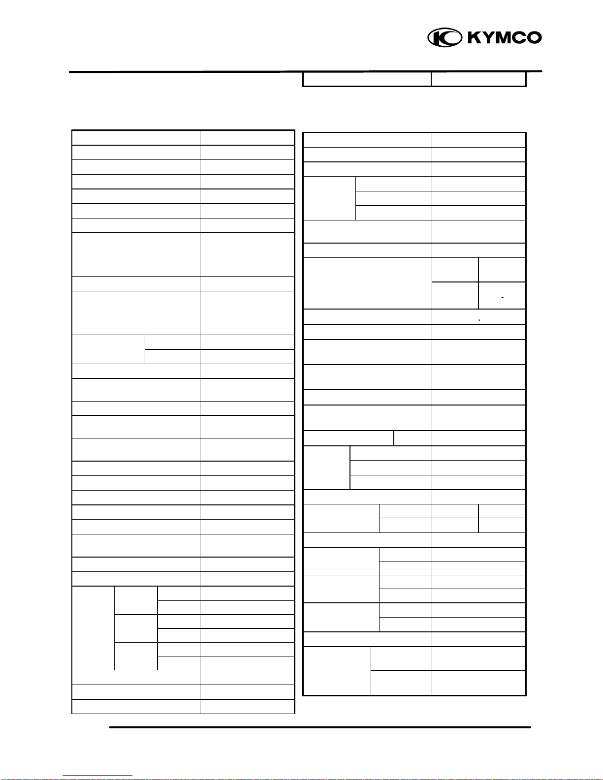
1. SPECIFICATIONS
1-1
ZX 50
SPECIFICATIONS
Name & Model SC10AS
Overall length (mm) 1792
Overall width (mm) 690
Overall height (mm) 1053
Wheel base (mm) 1225
Engine type Air cooled 2-stroke
Displacement (cc) 49.4 cc
Net weight (kg)
92.5
Seating capacity 2 riders (110kg)
Gross weight(kg)
150
Front wheel
120/70-12
Tires
Rear wheel
120/70-12
Ground clearance (mm) 170
Braking distance (m)
(Initial speed Km/h)
7m (30km/h)
Min. turning radius (mm) 1940
Starting system
Starting motor &
kick starter
Fuel type
Gasoline, 2-stroke
motor oil
Cylinder arrangement Single cylinder, flat
Combustion chamber type Semi -sphere
Valve arrangement Reed valve & piston
Bore x stroke (mm) 39 x 41.4
Compression ratio 7.3 : 1
Compression pressur e
(kg/cm ² rpm)
11.5kg/cm ²
Max. output (kw/rpm) 3.75/7000kw/rpm
Max. torque (kg-m/rpm) 4.5/6500 kg m/rpm
Open Automatic controlled
Intake
Close Automatic controlled
Port Open
timing
Exhaust
Close
Open
Scavenge
Close
Idle speed (rpm) 2100±100
Lubrication type Separate type
Oil pump type Plunger type
Oil filter type Full-flow filtration
Lubrication oil capacity (liter) 0.80
Air cleaner type & No. Wet, single
Fuel capacity (liter) 4.9
Type Plunger type
Carburetor Piston dia. (mm)
Venturi dia. (mm) 14
Ignition system type
CDI electromagnetic
Ignition
Ignition timing F mark 15.5°±2°BTDC/2000rpm
Spark
NGK BR8HSA
plug
ND
Spark plug gap (mm) 0.6 0.7
Battery capacity 12V3AH
Power to transmission gear
Power-transmission
gear-clutch
Reduction ratio of power to
transmission
Clutch type Dry multi-disc clutch
Transmission gear operation
type
Automatic centrifugal
type
Transmission ratio 1 spe
ed
Reduction Type Two-stage reduction
gear 1st reduction ratio
2nd reduction ratio
Transmission gear type Non-stage transmission
Tire pressure
Front wheel
1.50 1.75
(kg/cm ²)
Rear wheel 1.75 2.25
Turning angle Right & left 45°
Brake system
Front wheel
Expanding/hydraulic
type
Rear wheel
Expanding
Suspension
Front wheel
Telescope
type
Rear wheel
Unit swing
Shock absorber
Front wheel
Telescope
type
Rear wheel
Unit swing
Frame type Pipe under bone
CO 4.5% Exhaust
emission
concentration
HC 7000ppm Max
Page 4

2. GENERAL INFORMATION
2-0
ZX / SCOUT
1
__________________________________________________________________________________
__________________________________________________________________________________
__________________________________________________________________________________
__________________________________________________________________________________
__________________________________________________________________________________
GENERAL INFORMATION
__________________________________________________________________________________
ENGINE SERIAL NUMBER/IDENTIFICATION............................2- 1
SERVICE PRECAUTIONS ............................................................2- 2
SERVICE INFORMATION ............................................................2- 6
TORQUE VALUES........................................................................2- 8
SPECIAL TOOLS ..........................................................................2- 9
LUBRICATION POINTS...............................................................2-11
WIRING DIAGRAM......................................................................2-12
CABLE & HARNESS ROUTING...................................................2-13
TROUBLESHOOTING ..................................................................2-17
2
Page 5
2. GENERAL INFORMATION
2-1
ZX / SCOUT
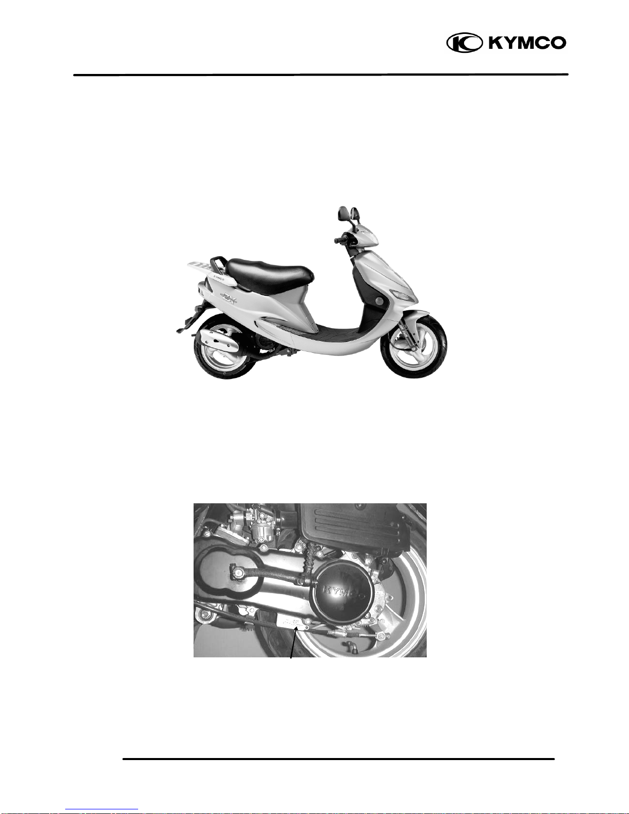
ENGINE SERIAL NUMBER/IDENTIFICATION
Location of Engine Serial Number
Page 6
2. GENERAL INFORMATION
2-2
ZX / SCOUT
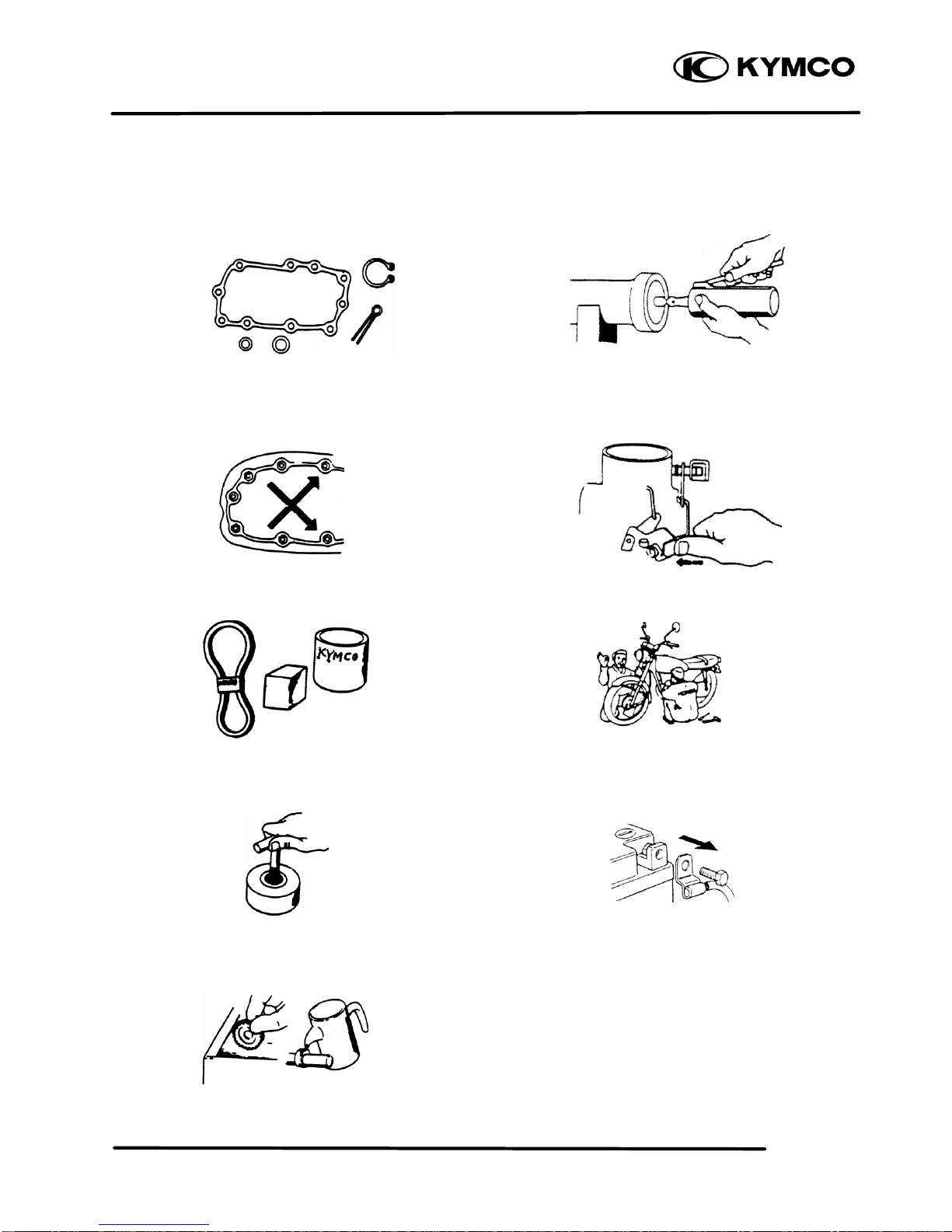
SERVICE PRECAUTIONS
n Make sure to install new gaskets, O-rings,
circlips, cotter pins, etc. when reassembling.
n When tightening bolts or nuts, begin with
larger-diameter to smaller ones at several
times, and tighten to the specified torque
diagonally.
n Use genuine parts and lubricants.
n When servicing the motorcycle, be sure to use
special tools for removal and installation.
n After disassembly, clean removed parts.
Lubricate sliding surfaces with engine oil
before reassembly.
n Apply or add designated greases and
lubricants to the specified lubrication points.
n After reassembly, check all parts for proper
tightening and operation.
n When two persons work together, pay
attention to the mutual working safety.
n Disconnect the battery negative (-) terminal
before operation.
n When using a spanner or other tools, make
sure not to damage the motorcycle surface.
n After operation, check all connecting points,
fasteners, and lines for proper connection and
installation.
n When connecting the battery, the positive (+)
terminal must be connected first.
n After connection, apply grease to the battery
terminals.
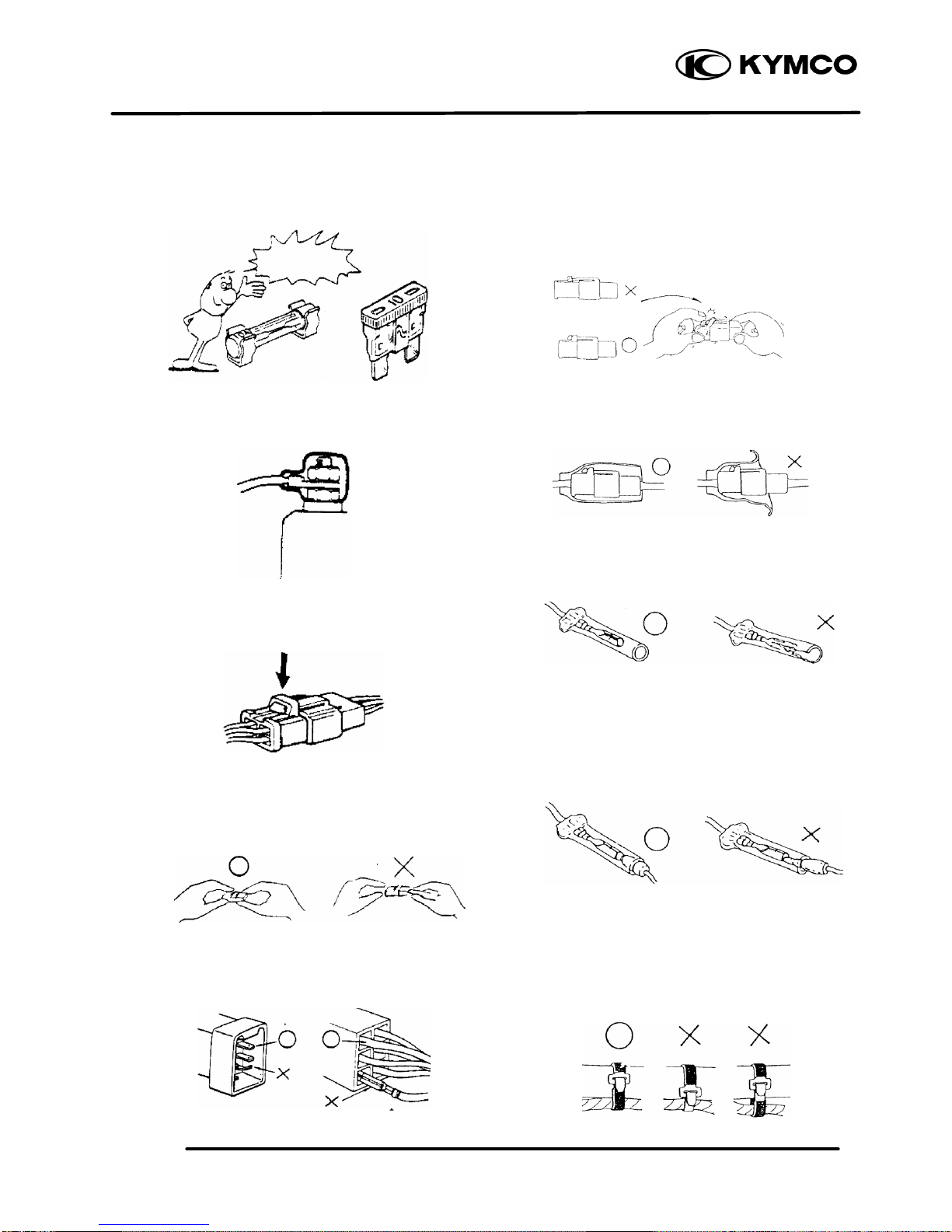
n Terminal caps shall be installed securely.
n If the fuse is burned out, find the cause and
repair it. Replace it with a new one according
Page 7
2. GENERAL INFORMATION
2-3
ZX / SCOUT
to the specified capacity.
n After operation, terminal caps shall be installed
securely.
n When taking out the connector, the lock on
the connector shall be released before
operation.
n Hold the connector body when connecting or
disconnecting it.
n Do not pull the connector wire.
n Check if any connector terminal is bending,
protruding or loose.
n The connector shall be inserted completely.
n If the double connector has a lock, lock it
at the correct position.
n Check if there is any loose wire.
n Before connecting a terminal, check for
damaged terminal cover or loose negative
terminal.
n Check the double connector cover for proper
coverage and installation.
n Insert the terminal completely.
n Check the terminal cover for proper coverage.
n Do not make the terminal cover opening face
up.
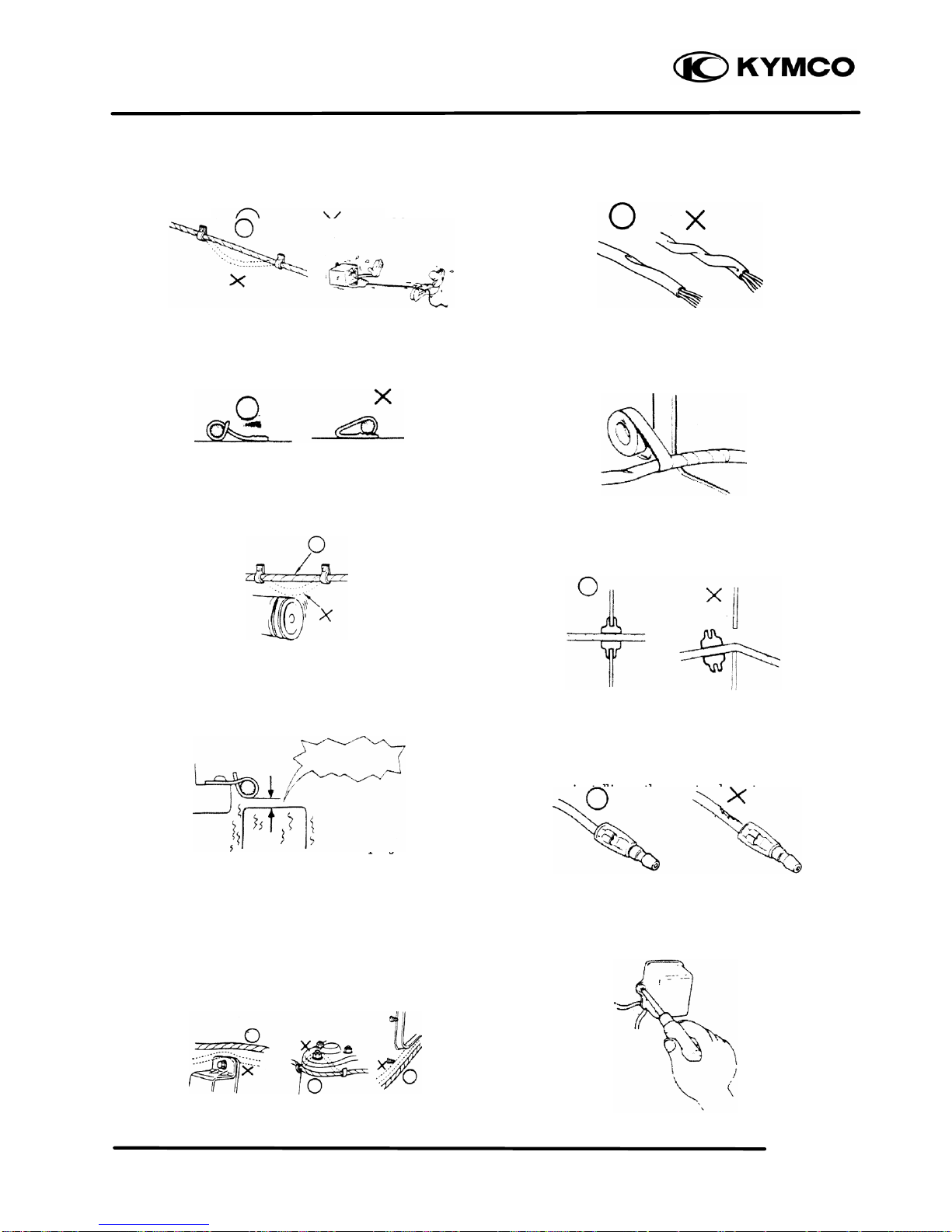
n Secure wire harnesses to the frame with their
respective wire bands at the designated
locations.
Tighten the bands so that only the insulated
surfaces contact the wire harnesses.
n After clamping, check each wire to make sure
it is secure.
Easy confirm
Page 8
2. GENERAL INFORMATION
2-4
ZX / SCOUT
n Do not squeeze wires against the weld or its
clamp.
n After clamping, check each harness to make
sure that it is not interfering with any moving or
sliding parts.
n When fixing the wire harnesses, do not make it
contact the parts which will generate high heat.
n Route wire harnesses to avoid sharp edges or
corners. Avoid the projected ends of bolts
and screws.
n Route wire harnesses passing through the side
of bolts and screws. Avoid the projected
ends of bolts and screws.
n Route harnesses so they are neither pulled
tight nor have excessive slack.
n Protect wires and harnesses with electrical
tape or tube if they contact a sharp edge or
corner.
n When rubber protecting cover is used to
protect the wire harnesses, it shall be installed
securely.
n Do not break the sheath of wire.
n If a wire or harness is with a broken sheath,
repair by wrapping it with protective tape or
replace it.
n When installing other parts, do not press or
squeeze the wires.
n After routing, check that the wire harnesses
are not twisted or kinked.
Don’t touch
Page 9
2. GENERAL INFORMATION
2-5
ZX / SCOUT
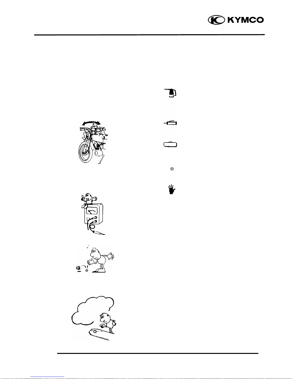
n Wire harnesses routed along with handlebar
should not be pulled tight, have excessive
slack or interfere with adjacent or surrounding
parts in all steering positions.
n When a testing device is used, make sure to
understand the operating methods thoroughly
and operate according to the operating
instructions.
n Be careful not to drop any parts.
n When rust is found on a terminal, remove the
rust with sand paper or equivalent before
connecting.
n Symbols:
The following symbols represent the servicing
methods and cautions included in this service
manual.
: Apply engine oil to the
specified points. (Use
designated engine oil for
lubrication.)
: Apply grease for lubrication.
: Use special tool.
: Caution
: Warning
(ð12-3) : Refer to page 12-3.
Engine Oil
Grease
Special
*
Remove the rest
Page 10
2. GENERAL INFORMATION
2-6
ZX / SCOUT
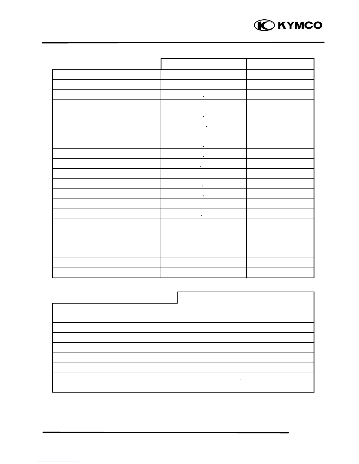
SERVICE INFORMATION
ENGINE
Standard (mm) Service Limit (mm)
Item SC10AS SC10AS
Cylinder head warpage 0.10
Piston O.D.(5mm from bottom of piston skirt) 38.955 38.970 38.90
Cylinder-to- piston clearance 0.10
Piston pin hole I.D. 12.002 12.008 12.03
Piston pin O.D. 11.994 12.0 11.98
Piston -to-piston pin clearance ← ←
Piston ring end gap (top/second) 0.10 0.25 0.40
Connecting rod small end I.D. 17.005 17.017 17.03
Cylinder bore 39.039.025 39.05
Drive belt width 18 17
Drive pulley collar O.D. 20.01 20.025 ←
Movable drive face ID. 20.035 20.085 19.97
Weight roller O.D. 13.0 12.4
Clutch outer I.D. 107 107.2 107.5
Driven face spring free length 87.9 82.6
Driven face O.D. ← ←
Movable driven face I.D. ← ←
Connecting rod big end side clearance ← ←
Connecting rod big end radial clearance ← ←
Crankshaft runout A/B ←
CARBURETOR
SC10AS
Venturi dia. 14mm
Identification number 014A
Float level 5.0mm
Main jet #80
Slow jet #35
Air screw opening 1 ±¼
Idle speed 2100±100rpm
Throttle grip free play 2 6mm
Jet needle clip notch 1st notch
Page 11
2. GENERAL INFORMATION
2-7
ZX / SCOUT
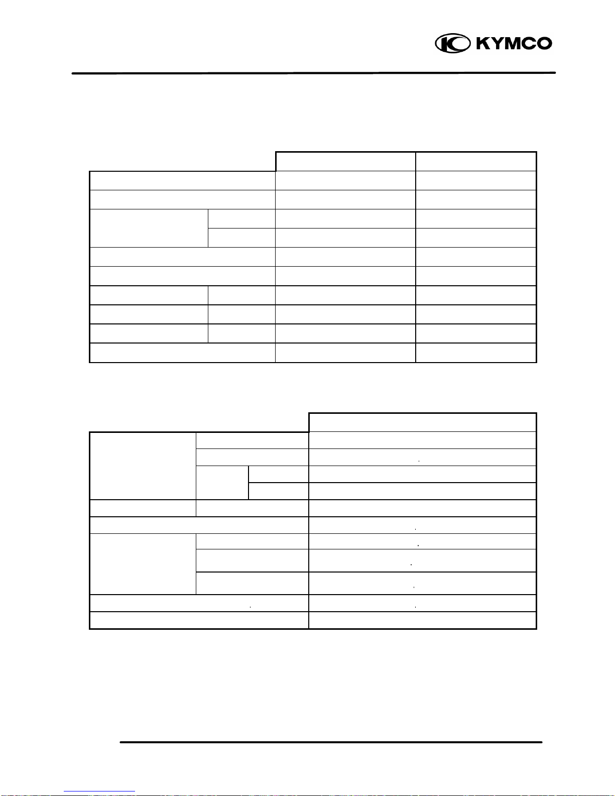
FRAME
Standard (mm) Service Limit (mm)
Item SC10AS SC10AS
Axle shaft runout 0.2
Radial
Front wheel rim runout
Axial
Front shock absorber spring free length 200.0 182.8
Rear wheel rim runout 2.0
Brake drum I.D. Front/rear 110 111
Brake lining thickness Front/rear 4.0/4.0 2.0/2.0
Brake disk runout Front/rear 0.30
Rear shock absorber spring free length 235.7 218.7
ELECTRICAL EQUIPMENT
SC10AS
Capacity 12V3AH
Voltag e 13.0 13.2V
Charging Standard 0.4A/5H
Battery
current Quick 4A/0.5H
Spark plug (NGK) BR8HSA
Spark plug gap 0.6 0.7mm
Primary coil 0.153 0.187Ω
Secondary coil
(with plug cap)
6.99 10.21KΩ
Ignition coil resistance
Secondary coil
(without plug cap)
3.24 3.96KΩ
Pulser coil resistance (20 ) 80 160Ω
Ignition timing 15.5°±2°BTDC/2000rpm
Page 12
2. GENERAL INFORMATION
2-8
ZX / SCOUT
TORQUE VALUES
ENGINE
Item Thread dia. (mm)
Torque (kg
-m)
Remarks
Cylinder head bolt
Clutch drive plate nut
Clutch outer nut
Drive face nut
Oil check bolt
Engine mounting bolt
Engine hanger bracket bolt
Exhaust muffler joint lock nut
Exhaust muffler lock bolt
Spark plug
BF7x115
10
NH10
NH12
10
BF10x95
BF10x50
NC6mm
BF8x35
1.5 1.7
3.5 4.0
3.5 4.5
5.0 6.0
1.0 1.5
4.5 5.5
3.5 4.5
1.0 1.4
3.0 3.6
1.1 1.7
(cold)
(cold)
FRAME
Item Thread dia. (mm)
Torque (kg
-m)
Remarks
Handlebar lock nut
Steering stem lock nut
Steering top cone race
Front axle nut
Rear axle nut
Rear brake arm bolt
Front shock absorber:
upper mount bolt
lower mount bolt
hex bolt
Front damper nut
Front pivot arm bolt
Rear shock absorber:
upper mount bolt
lower mount bolt
lower joint nut
10
25.4
25.4
12
16
8
8
10
8
8
4.5 5.0
8.0 12.0
0.5 1.3
5.0 7.0
11.0 13.0
3.3
3.3
1.5 3.0
1.5 3.0
3.5 4.5
2.4 3.0
1.5 2.5
Flange bolt/U-nut
Flange U-nut
Flange U-nut
Flange nut
Flange bolt/U-nut
Cross head
Apply locking agent
Flange screw/U-nut
Flange nut
Torque specifications listed above are for important fasteners. Others should be tightened to standard
torque values below.
STANDARD TORQUE VALUES SH bolt: 8mm Flange 6mm bolt
Item Torque (kg
-m)
Item Torque (kg
-m)
5mm bolt, nut
6mm bolt, nut
8mm bolt, nut
10mm bolt, nut
12mm bolt, nut
0.45 0.6
0.8 1.2
1.8 2.5
3.0 4.0
5.0 6.0
5mm screw
6mm screw, SH bolt
6mm flange bolt, nut
8mm flange bolt, nut
10mm flange bolt, nut
0.35 0.5
0.7 1.1
1.0 1.4
2.4 3.0
3.5 4.5
Page 13
2. GENERAL INFORMATION
2-9
ZX / SCOUT
SPECIAL TOOLS
Tool Name Tool No. Remarks
Universal bearing puller E030 Crankshaft bearing removal
Lock nut socket wrench F001 Top cone race holding
Lock nut wrench, F002 Stem lock nut tightening
Crankcase puller E026 Crankcase disassembly
Bearing remover set, 12mm
(Spindle assy, 12mm)
(Remover weight)
E020
Drive shaft bearing removal/installation
Bearing remover set, 15mm
(Spindle assy, 15mm)
(Remover head, 15mm)
(Remover shaft, 15mm)
E018
Drive shaft bearing removal/installation
Bearing outer driver, 28x30mm E014 Bearing installation
Clutch spring compressor E027 Driven pulley disassembly/assembly
Crankcase assembly collar E023
Driven shaft, crankshaft & crankcase
assembly
Crankcase assembly tool E024 Crankshaft & crankcase assembly
Ball race remover F005 Steering stem bearing races
Rear shock absorber compressor F004 Rear shock absorber disassembly/assembly
Universal holder E017 Flywheel holding
Flywheel puller E001 Flywheel removal
Bearing outer driver, 32x35mm E014
Drive shaft bearing installation
Final shaft bearing installation
Bearing outer driver, 37x40mm E014
Drive shaft bearing installation Final shaft
bearing installation Crankshaft bearing
installation
Universal bearing puller E030 Crankshaft bearing removal
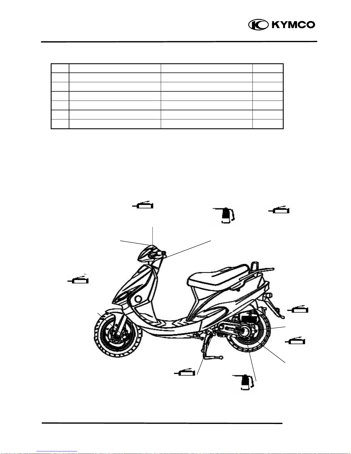
LUBRICATION POINTS
Page 14
2. GENERAL INFORMATION
2-10
ZX / SCOUT
ENGINE
NO.
Lubrication Points Lubricant Remarks
1 Crankcase sliding & movable parts JASO-FC or API-TC
2 Cylinder movable parts JASO-FC or API-TC
3 Transmission gear (final gear) SAE-90#
4 Kick starter spindle bushing Grease
5 Drive pulley movable parts Grease
6 Starter pinion movable parts Grease
FRAME
Apply clean engine oil or grease to cables and movable parts not specified. This will avoid abnormal
noise and rise the durability of the motorcycle.
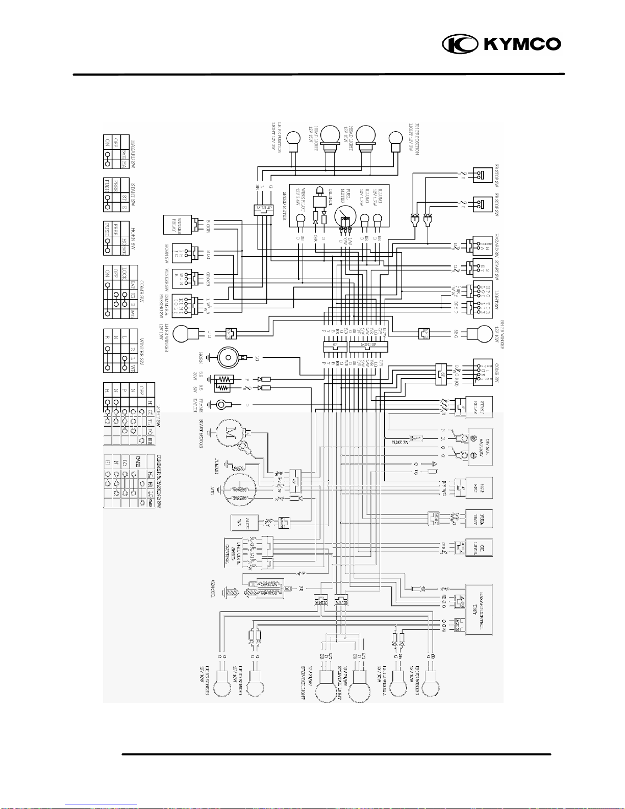
SC10AS WIRING DIAGRAM
Front/Rear Brake Lever
Seat Lock
Rear Wheel Bearing
Throttle Cable
Main Stand Pivot
Grease
Engine Oil
Grease
Engine Oil
Speedometer Gear/
Brake Cam/Front
Shock Absorber
Lower Mount
Bushings/Pivot
Grease
Grease
Grease
Grease
Engine Oil
Rear Brake Cable
Brake Cam/
Anchor Pin
Page 15
2. GENERAL INFORMATION
2-11
ZX / SCOUT
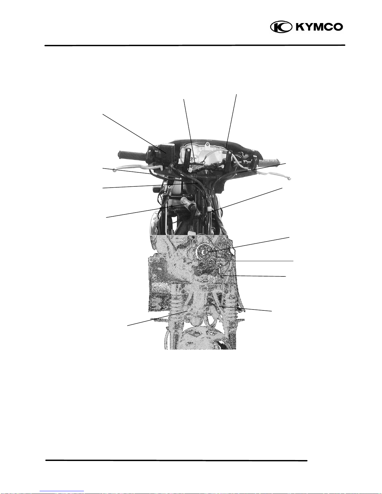
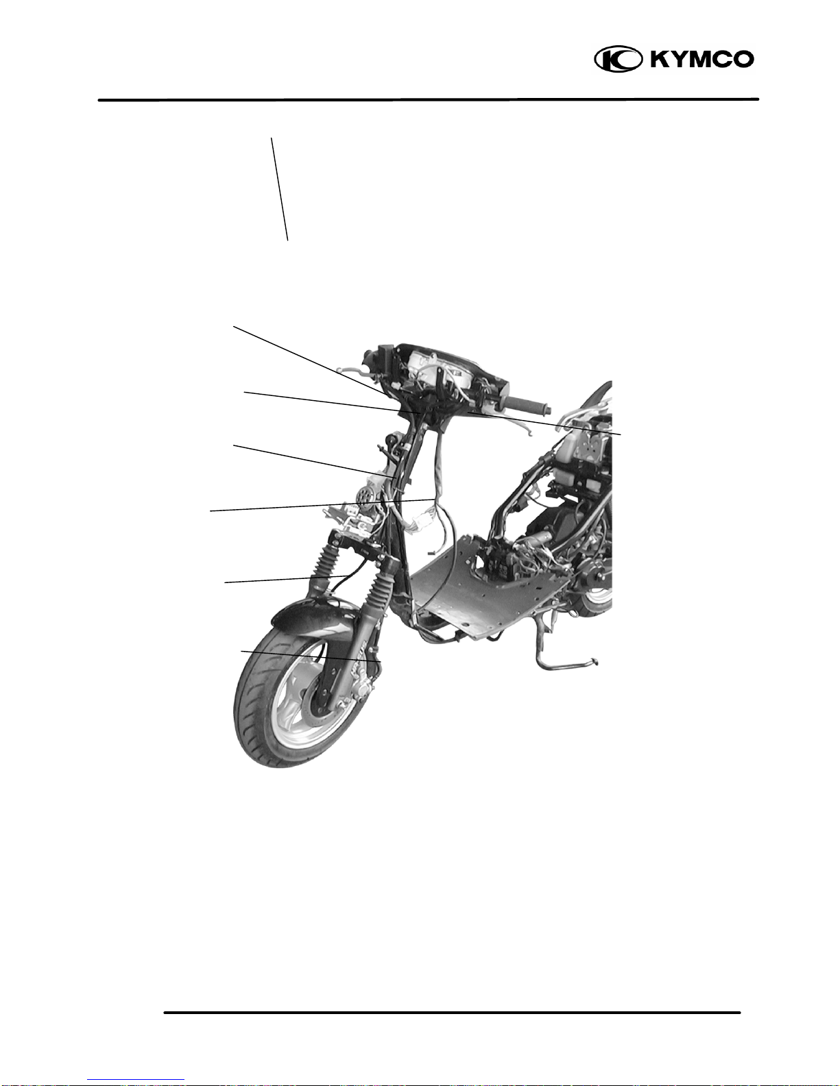
CABLE & HARNESS ROUTING
Page 16
2. GENERAL INFORMATION
2-12
ZX / SCOUT
Front Brake Reservoir
Rear Brake Cable
Throttle Cable
Ignition Switch
Regulator/Rectifier
Front Brake Fluid Tube
Resistor
Front Stop Switch Wire
Rear Stop Switch Wire
Speedometer Cable
Speedometer Cable
Front Brake Fluid Tube
Horn
Page 17
2. GENERAL INFORMATION
2-13
ZX / SCOUT
Ignition Coil
Fuel Unit
Wire Harness
Rear Brake Cable
Throttle Cable
Front Brake Fluid Tube
Speedometer Cable
Speedometer Cable
Front Brake Fluid Tube
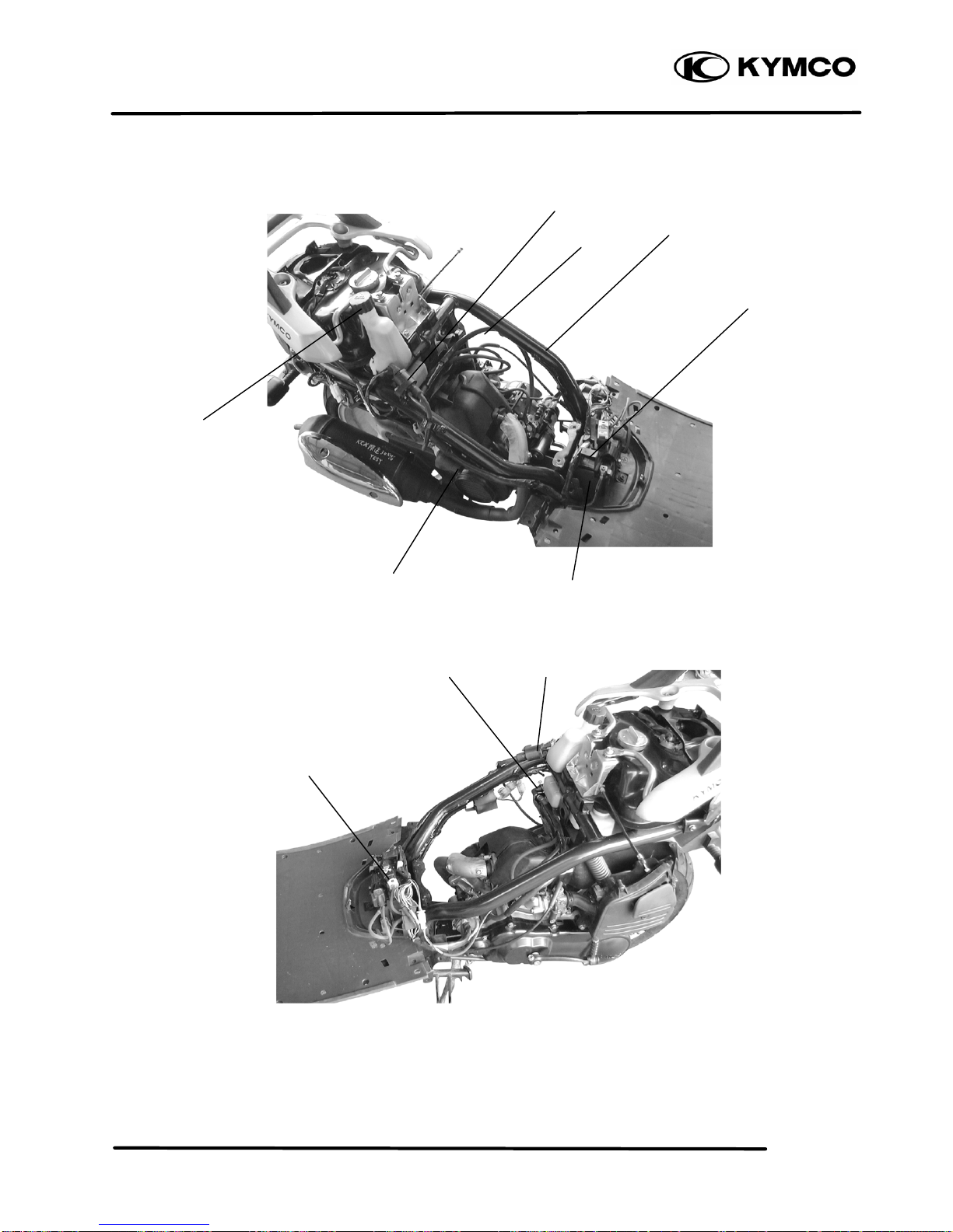
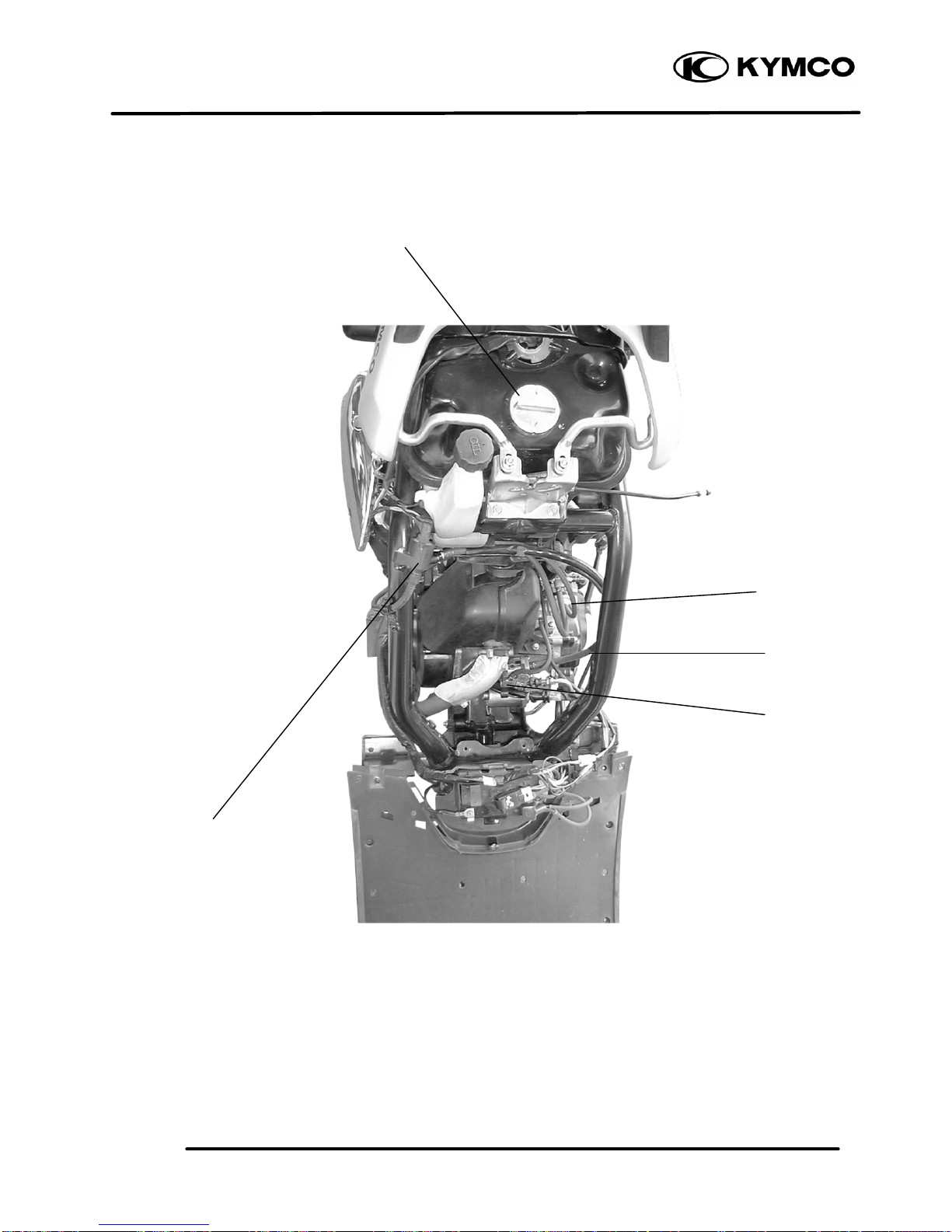
Page 18
2. GENERAL INFORMATION
2-14
ZX / SCOUT
Fuel Filter
Oil Tank Cap
Starter Relay
CDI Unit
Battery
Wire Harness
Ignition Coil
Oil Tube
Page 19
2. GENERAL INFORMATION
2-15
ZX / SCOUT
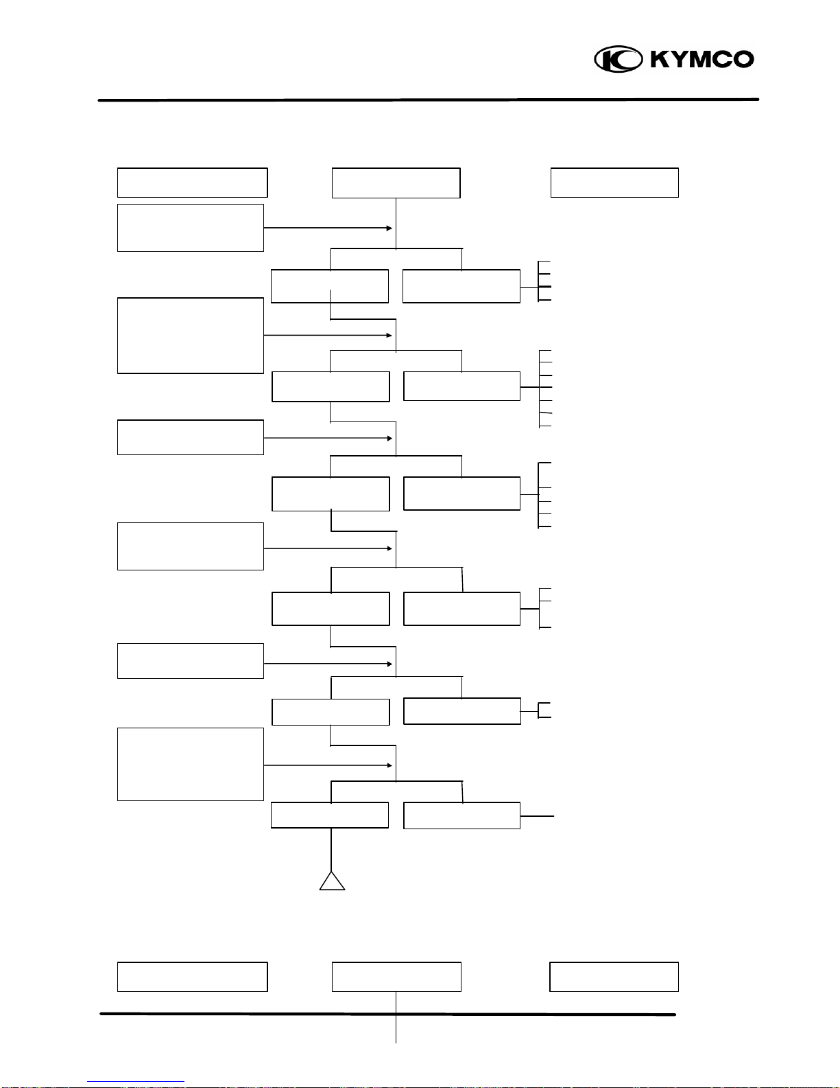
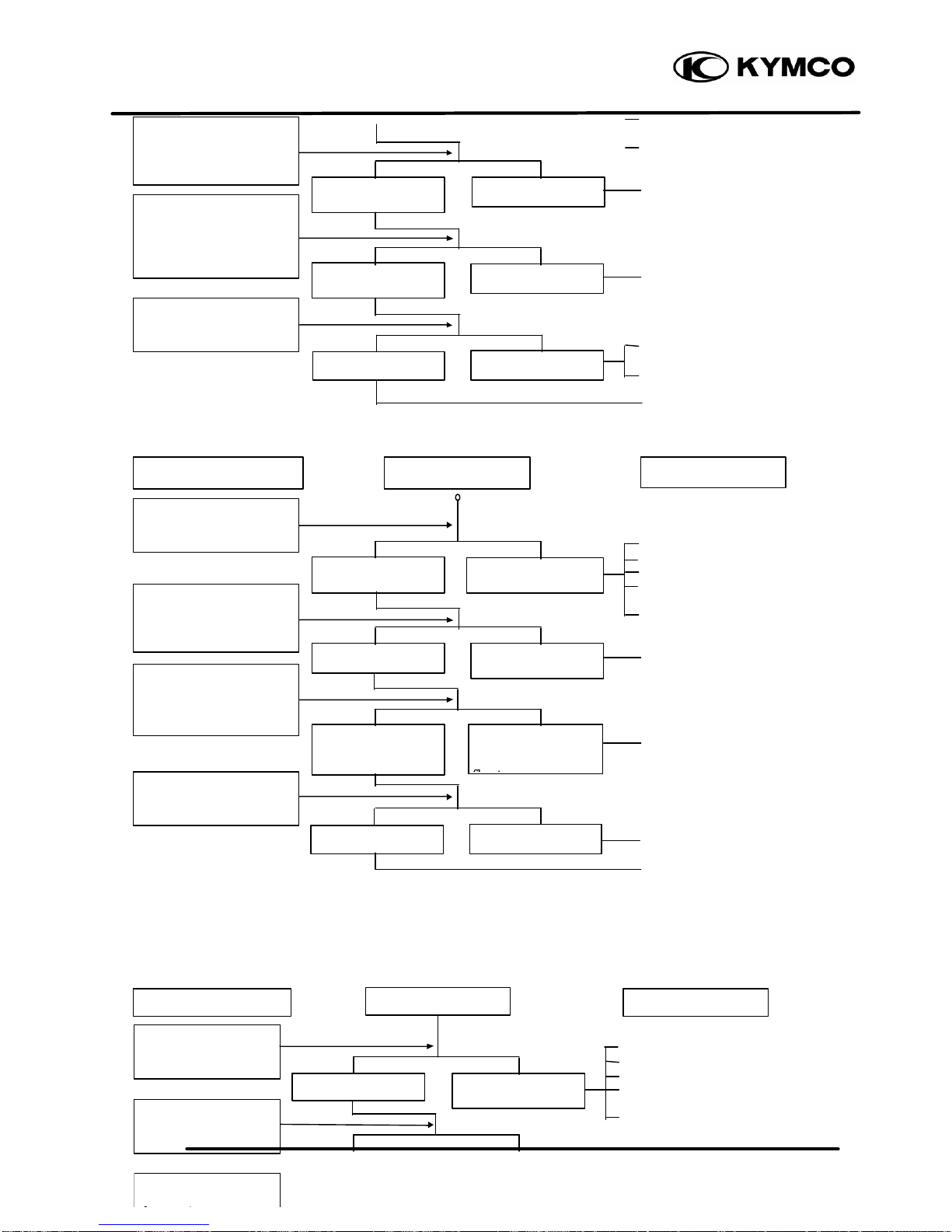
TROUBLESHOOTING
Vacuum Tee
Oil Pump
Ignition Coil
Oil Tube
Fuel Unit
Fuel Tank Cap
Page 20
2. GENERAL INFORMATION
2-16
ZX / SCOUT
ENGINE WILL NOT START OR IS HARD TO START
• Empty fuel tank
‚ Clogged float valve
ƒ Clogged fuel filter
„ Faulty auto fuel valve
• Faulty spark plug
‚ Fouled spark plug
ƒ Faulty CDI unit
„ Faulty A.C. generator
… Broken or shorted ignition coil
† Broken or shorted exciter coil
‡Faulty ignition switch
• Burned or worn cylinder
piston
‚ Faulty reed valve
ƒ Blown cylinder head gasket
„ Leaking crankcase
… Faulty crankcase oil seal
• Incorrectly adjusted idle speed
‚ Air leaking through intake
pipe
ƒ Incorrect ignition timing
• Flooded carburetor
‚ Throttle valve excessively
open
• Faulty auto bystarter
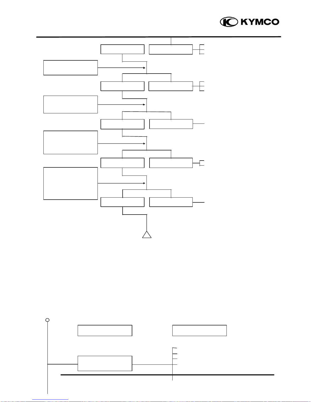
ENGINE STOPS IMMEDIATELY AFTER IT STARTS
Inspection/Adjustment Symptom Probable Cause
Check if fuel reaches
carburetor by loosening
drain screw.
Remove spark plug and
install it into spark plug
cap to test spark by
connecting it to engine
ground.
Inspection/Adjustment Symptom Probable Cause
Fuel reaches
carburetor
Spark jumps
Dry spark plug
Not clogged
Normal
compression
Engine does not
fire
Fuel does not
reach carburetor
Weak or no spark
Wet spark plug
Clogged
Low or no
compression
Engine fires but
does not start
Test cylinder
compression.
Remove spark plug and
inspect again.
Wait for
30 minutes and
then remove the
carbu-retor auto choke
circuit hose and blow
the hose with mouth.
Start engine by
follow-ing normal
starting procedure.
Page 21

2. GENERAL INFORMATION
2-17
ZX / SCOUT
• Empty fuel tank
‚ Clogged float valve
ƒ Clogged fuel filter
„ Faulty auto fuel valve
• Fouled spark plug
‚ Incorrect heat range plug
• Fouled spark plug
‚ Faulty CDI unit
ƒ Faulty A.C. generator
„ Faulty ignition coil
… Broken or shorted high
tension wire
† Faulty ignition switch
• Worn cylinder and piston rings
‚ Blown cylinder head gasket
ƒ Flaws in cylinder head
„ Faulty reed valve
… Seized piston
• Clogged carburetor jets
• Faulty CDI unit or A.C.
generator
‚ A.C.G. flywheel not aligned
• Mixture too rich (turn screw
out)
‚ Mixture too lean (turn screw
in)
Check if fuel reaches
carburetor by loosening
drain screw.
Fuel reaches
carburetor
Good spark
Remove spark plug and
install it into spark plug
cap to test spark by
connecting it to engine
ground.
Correct timing
Correctly adjusted
Plug not fouled or
discolored
Normal
compression
Not Clogged
Fuel does not
reach carburetor
Weak or inter
-
mittent spark
Incorrect timing
Incorrectly adjusted
Plug fouled or
discolored
Abnormal
compression
Clogged
Inspection/Adjustment
Symptom Probable Cause
Test cylinder
compression (using a
compression gauge).
Check carburetor for
clogging.
Check carburetor
gasket for air leaks.
Check ignition timing.
Check carburetor air
screw adjustment.
Remove spark plug and
install it into spark plug
cap to test spark by
connecting it to engine
ground.
Page 22
2. GENERAL INFORMATION
2-18
ZX / SCOUT
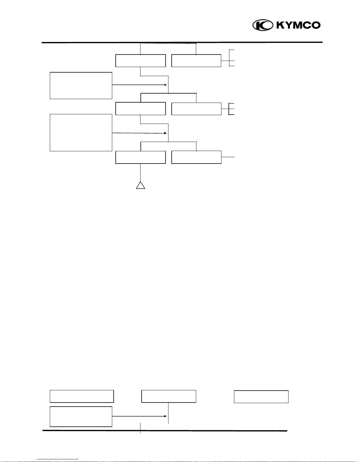
• Carburetor not securely
tightened
‚ Faulty intake manifold gasket
ƒ Deformed or broken
carburetor O-ring
• Broken cable
‚ Dirty auto bystarter
ƒ Faulty auto bystarter
• Faulty auto bystarter
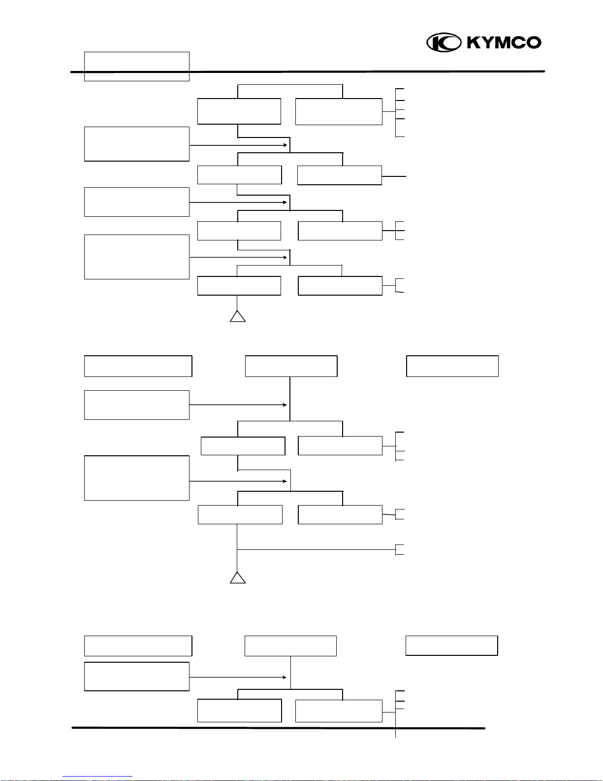
ENGINE LACKS POWER
Inspection/Adjustment Symptom
Probable Cause
No air leak
Not clogged
Clogged
Air leaks
Clogged
Not Clo gged
Connect auto bystarter
wire to battery. Wait for
5 minutes, then connect
a hose to fuel enriching
circuit and then blow
the hose with mouth.
Remove auto bystarter
connecting wire and
check if bypass fuel line
is clogged.
Start engine and
accelerate lightly for
observation.
Page 23
2. GENERAL INFORMATION
2-19
ZX / SCOUT
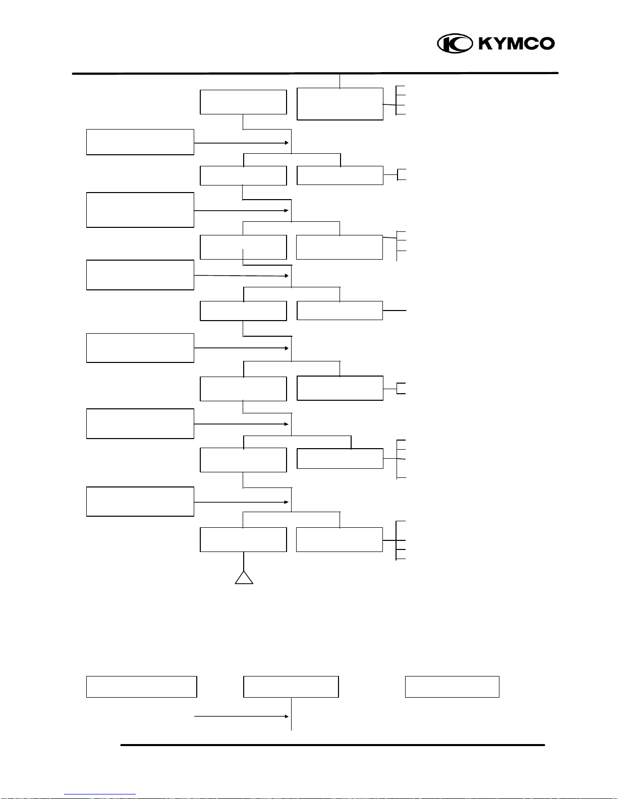
• Clogged air cleaner
‚ Clogged fuel filter
ƒ Clogged exhaust muffler
„ Faulty auto bystarter
• Faulty CDI unit
‚ Faulty A.C. generator
• Worn cylinder and piston rings
‚ Blown cylinder head gasket
ƒ Faulty reed valve
• Clogged carburetor jets
• Fouled spark plug
‚ Incorrect heat range plug
• Mixture too lean
‚ Poor quality fuel
ƒ Excessive carbon build -up in
combustion chamber
„ Ignition timing too early
• Excessive carbon build -up in
combustion chamber
‚ Poor quality fuel
ƒ Clutch slipping
„ Mixture too lean
POOR PERFORMANCE (ESPECIALLY AT IDLE AND LOW SPEEDS)
Engine speed
increases
Engine overheats
Correct timing
Inspection/Adjustment
Engine does not
knock
Symptom
Plug not fou
led or
discolored
Probable Cause
Normal
compression
Not Clogged
Engine speed does
not increase
sufficiently
Engine does not
overheats
Incorrect timing
Engine knocks
Plug fouled or
discolored
Abnormal
compression
Clogged
Check ignition timing
(using a timing light).
Rapidly accelerate or
run at high speed
Test cylinder
compression (using a
compression gauge)
Check carburetor for
clogging
Remove spark plug and
inspect
Check if engine
overheats
Page 24
2. GENERAL INFORMATION
2-20
ZX / SCOUT
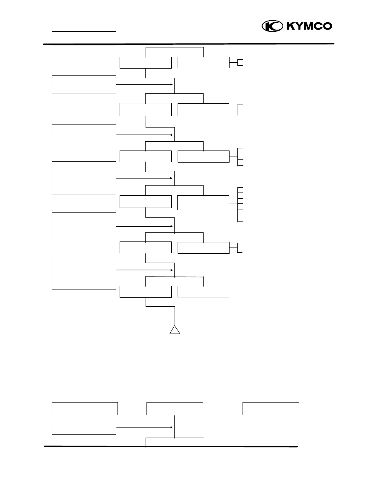
• Faulty CDI unit
‚ Faulty A.C. generator
• Mixture too rich (turn screw
out)
‚ Mixture too lean (turn screw
in)
• Carburetor not securely
tightened
‚ Faulty intake manifold gasket
ƒ Deformed carburetor O-ring
• Faulty or fouled spark plug
‚ Faulty CDI unit
ƒ Faulty A.C. generator
„ Faul ty ignition coil
… Broken or shorted high
tension wire
† Faulty ignition switch
• Broken auto bystarter wire
‚ Faulty auto bystarter
POOR PERFORMANCE (AT HIGH SPEED)
Clogged Not clogged
Inspection/Adjustment Symptom Probable Cause
Check ignition timing.
Remove spark plug and
install it into spark plug
cap to test spark by
connecting it to engine
ground.
Check ignition timing.
Connect auto bystarter
wire to battery. Wait for
5 minutes, then connect
a hose to fuel enriching
circuit and then blow
the hose with mouth.
Remove auto bystarter
connecting wire and
check if bypass fuel line
is clogged.
Check carburetor
gasket for air leaks.
Check carburetor air
screw adjustment.
Correct timing
Incorrect timin g
Correctly adjusted
Incorrectly adjusted
No air leak
Air leaks
Good spark
Weak or inter
-
mittent spark
Not clogged
Clogged
Page 25
2. GENERAL INFORMATION
2-21
ZX / SCOUT
• Faulty CDI unit
‚ Loose A.C.G. stator
ƒ Faulty A.C. generator
• Empty fuel tank
‚ Clogged fuel tube or filter
ƒ Clogged charcoal canister
• Clean and unclog
• Broken auto bystarter wire
‚ Faulty auto bystarter
• Faulty auto bystarter
CLUTCH, DRIVE AND DRIVEN PULLEYS
• Worn or slipping drive belt
‚ Broken ramp plate
ƒ Broken driven face spring
„ Separated clutch lining
Clogged Not clogged
Engine starts but
motor-cycle does not
Symptom
Probable Cause
Connect auto bystarter
wire to battery. Wait for
5 minutes, then connect
a hose to fuel enriching
circuit and then blow
the hose with mouth.
Remove auto bystarter
connecting wire and
check if bypass fuel line
is clogged.
Check carburetor jets
for clogging.
Check auto fuel valve
for fuel supply.
Correct timing
Incorrect timing
Fuel flows freely Fuel flow restricted
Not clogged
Clogged
Not clogged Clogged
Page 26
2. GENERAL INFORMATION
2-22
ZX / SCOUT
… Damaged driven pulley shaft splines
† Damaged final gear
‡ Seized final gear
• Broken shoe spring
‚ Clutch outer and clutch weight stuck
ƒSeized pivot
• Worn or slipping drive belt
‚ Worn weight rollers
ƒ Seized drive pulley bearings
„ Weak driven face spring
… Worn or seized driven pulley bearings
• Worn or slipping drive belt
‚ Worn weight rollers
ƒ Worn or seized driven pulley bearings
• Oil or grease fouled drive belt
‚ Worn drive belt
ƒ Weak driven face spring
„ Worn or seized driven pulley bearings
STEERING HANDLEBAR DOES NOT TRACK STRAIGHT
(Front and rear tire pressures are normal)
• Steering stem nut too tight
‚ Broken steering steel balls
• Excessive wheel bearing play
‚ Bent rim
ƒ Loose axle nut
• Misaligned front and rear wheels
‚ Bent front fork
POOR SUSPENSION PERFORMANCE
(Front and rear tire pressures are normal)
• Weak shock spring
‚ Excessive load
Engine lacks power at
start of a grade (poor
slope performance)
Steering is heavy
Suspension is too soft
Front or rear wheel is
wobbling
Symptom
Symptom
Probable Cause
Probable Cause
Engine lacks power at
high speed
There is abnormal noise
or smell while running
Motorcycle creeps or
engine starts but soon
stops or seems to rush
out (Rear wheel rotates
when engine idles)
Steering handlebar pulls
to one side
Page 27
2. GENERAL INFORMATION
2-23
ZX / SCOUT
ƒ Shock damper oil leaking
• Bent fork tube or shock rod
‚ Fork slid er and tube binding
• Fork tube and spring binding
‚ Fork slider and tube binding
POOR BRAKE PERFORMANCE
(Adjust brake according to standards)
• Worn brake linings
‚ Worn brake cam contacting area on
brake shoes
ƒ Worn brake cam
„ Worn brake drum
• Worn brake linings
‚ Foreign matter on brake linings
ƒ Rough brake drum contacting area
• Sluggish or elongated brake cables
‚ Brake shoes improperly contact
brake drum
ƒ Water and mud in brake system
„ Oil or grease on brake linings
• Faulty brake master cylinder
‚ Faulty brake caliper
ƒ Oil or grease on brake disk
„ Deformed brake disk
… Leaking brake fluid tube
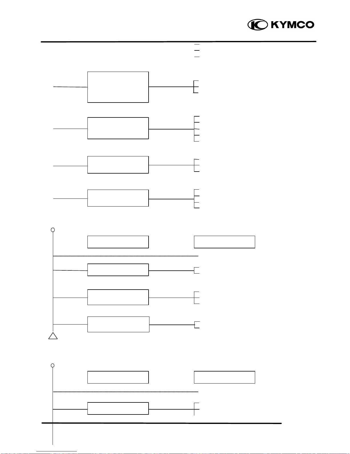
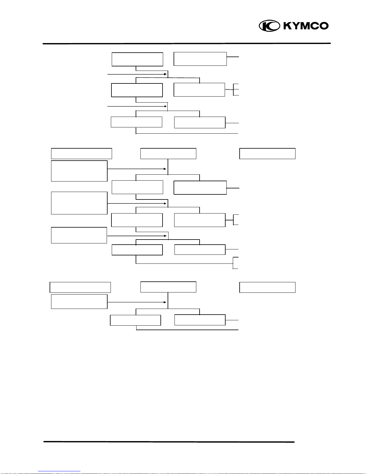
OIL METER
1. Motor oil indicator light does not come on when there is no motor oil (Ignition switch ON)
Inspection/Adjustment Symptom Probable Cause
Brake squeaks
Symptom
Probable Cause
Suspension is too hard
Suspension is noisy
Brake performance is
poor
Index mark on brake
panel aligns with wear
indicator arrow
Expanding
Brake
Hydraul
ic
Brake
Page 28
2. GENERAL INFORMATION
2-24
ZX / SCOUT
Faulty
• Burned out fuse
‚ Weak or dead battery
ƒ Faulty ignition switch
„ Loose or disconnected
connector
… Broken wire harness
•Burned out bulb
• Loose wire connector
‚ Broken wire harness
ƒ Incorrectly connected wire
• Faulty float
‚ Broken or shorted wire in
meter
2. Motor oil is sufficient but the indicator light remains on (Ignition switch ON)
• Loose or disconnected
connector
‚ Broken wire harness
ƒ Incorrectly connected wire
• Faulty float
‚ Broken or shorted wire in
meter
• Damaged oil tank
‚ Foreign matters in oil tank
FUEL GAUGE
1. Pointer does not register correctly (Ignition switch ON)
• Burned out fuse
‚ Weak or dead battery
ƒ Faulty ignition switch
Inspection/Adjustment Symptom
Inspection/Adjustment Symptom Probable Cause
Signals operate
properly
Signals dim, remain
on or don‘t operate
Signals operate
properly
Signals dim, remain
on or don‘t operate
Bulb lights Bulb does not light
Good
Faulty
Remov
e oil meter and
check operation of
indicator light by moving
float
Check connectors for
proper connection.
Good
Probable Cause
Good
Faulty
Remove oil meter and
check operation of
indicator light by moving
float
Check connectors for
proper operation.
Connect indicator light
bulb to battery for bulb
inspection.
Check battery circuit by
operating turn signals.
Good
Faulty
Check battery circuit by
operating turn signals.
Float up = Light off
Float down = Light on
Float up = Light off
Float down = Light on
Page 29
2. GENERAL INFORMATION
2-25
ZX / SCOUT
„ Loose or disconnected
connector
… Broken wire harness
• Faulty float
• Broken or shorted fuel unit
wire
• Loose or disconnected
connector
‚ Incorrectly connected
connector
• Broken or shorted wire in
fuel gauge
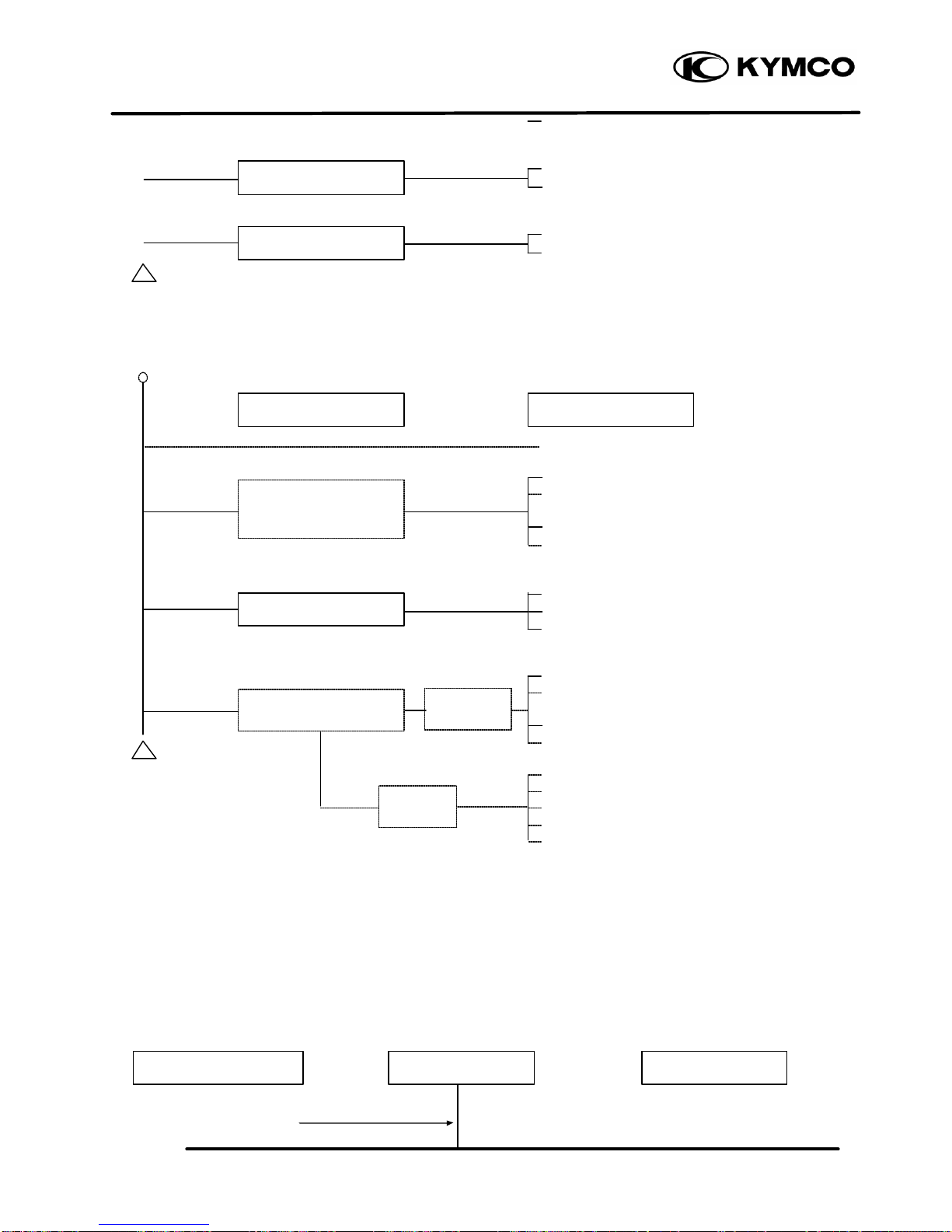
2. Pointer fluctuates or swings (Ignition switch ON)
• Burned out fuse
‚ Weak or dead battery
ƒ Faulty ignition switch
„ Loose or disconnected
connector
… Broken wire harness
• Poor contact in fuel unit
• Insufficient damping oil in
fuel gauge
• Loose or disconnected
connector
• Broken or shorted wire in
fuel gauge
STARTER MOTOR
1. Starter motor won‘t turn
• Burned out fuse
‚ Weak or dead battery
ƒ Faulty stop switch
„ Loose or disconnected
connector
… Broken or shorted ignition
Inspection/Adjustment
Symptom
Inspection/Adjustment Symptom
Stoplight does not
come on
Stoplight comes on
Signals operate
properly
Signals
dim, remain
on or don‘t operate
Pointer does not
move
Pointer does not
move
Good
Good
Pointer moves
Pointer moves
Pointer moves
Pointer does not
move in
accord
-
ance with
Probable Cause
Faulty
Faulty
Pointer does not
move
Pointer moves in
accordance with
float
Probable Cause
Check operation of
stop switch by
applying brake.
Check battery circuit
by operating turn
signals.
Remove fuel unit and
check operation of
pointer by moving float
up and down.
Check operation of
pointer by opening and
shorting fuel unit
terminal on wire
harness side.
Check connectors for
proper connection.
Chec
k operation of
starter relay by
Remove fuel unit and
check operation of
pointer by moving float
up and down.
Check battery circuit by
operating turn signals
and horn.
Move float up and down
rapidly (1 round /sec.)
to check the operation
of pointer.
Check connectors for
proper connection.
Page 30
2. GENERAL INFORMATION
2-26
ZX / SCOUT
switch wire
• Faulty or weak battery
• Poor starter button connection
‚ Faulty starter relay
ƒ Loose or disconnected
connector
• Faulty starter motor
• Faulty wire harness
2. Starter motor turns slowly or idles
• Weak or dead battery
• Loose or disconnected
connector
‚ Faulty starter relay
• Seized cylinder
• Broken or shorted starter
motor cable
‚ Faulty starter pinion
3. Starter motor does not stop turning
• Faulty starter pinion
• Starter relay shorted or stuc k
closed
Inspection/Adjustment
Inspection/Adjustment
Symptom
Symptom
Signals o
perate
properly
Signals operate
properly
Signals dim, remain
on or don‘t operate
S
ignal
s dim, remain
on or don‘t operate
Starter motor turns
Turns easily
Not stopped
Starter does not
Hard to turn
Stopped
Relay operates
properly
Starter motor
turns slowly
Probable Cause
Probable Cause
Relay does not
operate
Starter motor
turns normally
Check battery circuit
by operating turn
signals.
Turn ignition
switch
OFF.
Connect starter
motor directly to
battery.
Rotate crankshaft.
Page 31

3. INSPECTION/ADJUSTMENT
3-0
ZX /SCOUT 50
3
__________________________________________________________________________________
__________________________________________________________________________________
__________________________________________________________________________________
__________________________________________________________________________________
__________________________________________________________________________________
INSPECTION/ADJUSTMENT
__________________________________________________________________________________
INSPECTION AND MAINTENANCE SCHEDULE........................3- 1
BRAKE SYSTEM...........................................................................3- 4
MOVING DEVICE.........................................................................3- 5
DAMPING DEVICE.......................................................................3- 6
POWER DRIVE SYSTEM .............................................................3- 6
ELECTRICAL EQUIPMENT ..........................................................3- 7
ENGINE.........................................................................................3- 8
OTHERS........................................................................................3- 11
3
Page 32

3. INSPECTION/ADJUSTMENT
3-1
ZX /SCOUT 50
INSPECTION AND MAINTENANCE SCHEDULE
(Note) 1. means time for inspection.
2. means regular replacement for the specified parts.
This inspection and maintenance schedule is based upon average riding conditions. Machines
subjected to serve use, or ridden in unusually dusty areas, require more frequent servicing.
Frequency
Inspection & Maintenance Item
Preride
1st
month
Every
6
month
s
Every
12
months
Judgment Standards Remarks
Check for looseness and
vertical play
Steering
handlebar
Operating performance
Right/left turning angle
Suspension
Damage
Check for front fork
pivot installation
Check
steering
stem
Front
fork
Check front fork pivot
for looseness and
abnormal noise
Check
steering
stem
Front/rear brake lever
free play
Free play:
10 20mm
Brake lever operation
Brake
Lever
Brake performance
Lever/
Cable
Looseness, abnormal
noise and damage
Brake
System
Drum-to-lining
clearance
Brake shoe and lining
wear
Indi cator
type
Brake
drum/
shoe
Brake drum wear and
damage
Standard:
Front: 110 mm
Rear : 110 mm
Service Limits:
Front: 111 mm
Rear : 111 mm
Moving
Device
Tire Tire pressure
Front Rear
1
rider
1.50
kg/cm²
1.75
kg/cm²
Tire
Size
120/70-12 120/70-1
2
Page 33

3. INSPECTION/ADJUSTMENT
3-2
ZX /SCOUT 50
Frequency
Inspection & Maintenance Item
Preride
1st
month
Every
6
month
s
Every
12
months
Judgment Standards Remarks
Tire crack and damage
Tire groove and
abnormal wear
Groove Depth:
Front: 0.8mm
Rear : 0.8mm
Imbedded objects,
gravel, etc.
Moving
Device
Motorcycle
Axle nut looseness
Torque Values:
Front axle nut
5.0 7.0kg-m
Rear axle nut
11.0 13.0kg-m
Axle nut
torque
Check wheel rim, rim
edge and spoke plate for
damage
Rim runout at rim end:
Front: Axial 2.0mm
Radial 2.0mm
Rear: Axial 2.0mm
Radial 2.0mm
Check front wheel
bear-ing for excessive
play and abnormal noise
Check front wheel
bear-ing for excessive
play and abnormal noise
Frame
Spring
Damage
Shock
spring
free
length
Suspen -si
on arm
Connecting parts
loose-ness and arm
damage
Shock
Oil leakage and damage
Damping
Device
absorber
Assembly parts
loose-ness abnormal
noise
Power
Clutch Operation
Drive
System
Transmission case
Oil leakage and oil level
Oil level:
Oil check bolt hole
at lower hole edge
Rear wheel
transmission case
Ignition
device
Spark plug condition
Plug gap: 0.60.7mm
Page 34

3. INSPECTION/ADJUSTMENT
3-3
ZX /SCOUT 50
Electrical
Equipment
Battery Terminal connection
Wires
Loose connection and
damage
Frequency
Inspection & Maintenance Item
Preride
1st
month
Every
6
month
s
Every
12
months
Judgment Standards Remarks
Performance and abnormal
noise
Body
Conditions at low and high
speeds
Exhaust smoke
Air cleaner
Oil quality and quantity
r Oil level indicator
Indicator light comes on
when oil is insufficient
Engine
Oil leakage
Oil level
Lubrication
system
Check oil filter for clogging
Fuel leakage
Carburetor, throttle valve and
auto bystarter
Check fuel filter for clogging
Fuel level
Fuel
System
Fuel tube replacement
Every 4 years
Operation
Lights & Winker
Winking action, dirt and
damage
Buzzer &
Steering Lock
Operation
Rearview Mirror
& Reflector
Rearview mirror position
Rearview
Mirror
Reflector &
License Plate
Dirt and damage
Counter Operation
Exhaust
Joint looseness and damage
Muffler
Exhaust muffler performance
Body & Frame Looseness and damage
Page 35

3. INSPECTION/ADJUSTMENT
3-4
ZX /SCOUT 50
Abnormal
Conditions
Happened Last
Time
Check if the abnormal
conditions occur again
Lubrication points
Others
Remove carbon deposits on
combustion chamber,
breather hole and exhaust
muffler
BRAKE DRUM/SHOE
«Brake Shoe Wear»
Replace the brake shoes if the arrow on the
brake arm aligns with reference mark“” on the
brake panel when the brake is fully applied.
«Brake Drum Wear/Damage»
Check the brake drum appearance for damage.
Check if the brake lining wear is within the
specified service limit. Check the brake
operation for abnormal noise and brake drum
inside for wear or damage.
BRAKE DISK/LINING
«Brake Disk Surface and Brake Pad
Wear»
Check the brake disk surface for scratch.
Check if the brake pad wear is within the
specified service limit.
«Brake Disk Runout Inspection»
Jack the motorcycle wheels off the ground and
check if the brake disk runout is within the
specified service limit.
BRAKE FLUID LEVEL INSPECTION
«Brake Master Cylinder Fluid Level
Inspection »
Turn the steering handlebar upright and check
if the front brake fluid level is within the
specified limits through the front brake master
cylinder check hole.
“” Marks <Rear>
Adjusting Nuts
<Front>
Page 36

3. LUBRICATION SYSTEM
3-5
MOVING DEVICE
TIRES
«Tire Pressure»
Check the tire pressure.
Tire Pressure (one rider)
Front: 1.50 kg/cm²
Rear: 1.75 kg/cm²
Tire Size:
Front: 120/70-12
Rear: 120/70-12
«Axle Nut/Axle Shaft Looseness»
Check the front and rear axle nuts for
looseness.
If the axle nuts are loose, tighten them to the
specified torques.
Torques:
Front: 5.0 7.0kg-m
Rear: 11.0 13.0kg-m
«Wheel Rim/Spoke Plate Damage»
Check the wheel rim and spoke plate for wear or
damage and measure the rim runout.
Tire pressure should be checked when
tires are cold.
*
Brake Disk
Brake Lining Service
Limit Mark
Brake Master Cylinder
Page 37

3. INSPECTION/ADJUSTMENT
3-6
DAMPING DEVICE
SHOCK ABSORBERS
«Oil Leak/Damage»
Fully apply the front brake and check the
action of the front shock absorber by
compressing it several times.
Check the entire shock absorber assembly for
looseness or damage.
Check the action of the rear shock absorber
by compressing it several times.
Check the entire shock absorber assembly for
looseness or damage.
POWER DRIVE SYSTEM
TRANSMISSION CASE
Check the rear wheel transmission case
surrounding area for oil leaks.
Stop the engine and remove the oil check bolt.
The gear oil level shall be at the oil check bolt
hole. If the oil level is low, add the specified
oil to the proper level.
Specified Gear Oil: SAE10W90#
Install and tighten the oil check bolt.
Torque: 1.0 1.5kg-m
Start the engine and check for oil leaks.
Axle Nut
Place the motorcycle on its main stand on
level ground.
*
Axle Nut
Rear Wheel
Page 38

3. LUBRICATION SYSTEM
3-7
ELECTRICAL EQUIPMENT
IGNITION APPARATUS
«Spark Plug»
Remove the frame center cover.
Remove the spark plug cap and spark plug.
Check the spark plug for wear, fouling and
carbon deposits.
Remove the fouling and carbon deposits with a
spark plug cleaner or wire brush.
Specified Spark Plug
BR8HSA
Spark Plug Gap: 0.6 0.7mm
«Ignition Apparatus»
Remove the right side rail. (ð12-4)
Remove the A.C. generator fan cover.
(ð7-3)
Remove the four bolts attaching the fan and
then remove the fan.
Warm up the engine and check the ignition
timing with a timing light.
When the engine is running at the specified rpm, the
ignition timing is correct if the “F” mark on the
flywheel aligns with the index mark on the
crankcase within ±2°.
Ignition Timing:
15.5°±2°BTDC/2000rpm
Gap, Wear and
Fouling Deposits
Washer Damage
Cracks
Bolt
The CDI ignition timing is not adjust
-
able.
If the timing is incorrect, check the CDI
unit, ignition coil and A.C. generator and
replace any faulty parts.
*
0.6-0.7mm
Page 39

3. INSPECTION/ADJUSTMENT
3-8
ENGINE
BODY
«At High and Low Speeds»
Adjust the idle speed to the specified range by
turning the throttle stop screw and air screw.
Idle Speed:
2100±100rpm
«Air Cleaner»
Remove the air cleaner cover by removing the
six air cleaner cover screws.
Remove the air cleaner element.
The engine must be warm for accurate idle
speed adjustment.
*
Screws
Air Screw
Throttle Stop Screw
Index Mark
F Mark
Page 40

3. LUBRICATION SYSTEM
3-9
Wash the air cleaner element in detergent oil,
squeeze out and allow to dry.
After washing, soak the element in clean engine
oil SAE 15W-40# and squeeze out excess oil.
Reinstall the element.
«Cylinder Compression»
Remove the spark plug and insert a
compression gauge.
Open the throttle valve fully and push the
starter button for 7 8 seconds to test the
compression.
Compression :
11.5kg/cm ²
If the compression is low, check for the
following:
• Leaking cylinder head gasket
• Worn piston/cylinder
If the compression is high, it indicates that
carbon deposits have accumulated on the
combustion chamber and the piston head.
LUBRICATION SYSTEM
«Oil Filter Cleaning»
Disconnect the oil tube at the oil pump side and
allow oil to drain into a clean container.
Remove the tube clip at the oil tank side and
disconnect the oil tube.
Remove the oil filter.
Soak in oil
Air Cleaner
Squeeze out
and dry
Wash
Squeeze out
excess oil
Warm up the engine before compression
test.
*
Never use gasoline or organic vaporable
oil with acid or alkali for washing.
*
Page 41

3. INSPECTION/ADJUSTMENT
3-10
Clean the oil filter screen with compressed air.
Install the oil filter in the reverse order of
removal and fill the oil tank with specified oil
up to the proper level.
Bleed air from the oil pump and oil lines.
«Oil Pump Condition»
Open the throttle valve fully and check that the
index mark on the pump body aligns with the
aligning mark on the oil pump control lever.
Reference tip alignment within 1mm of index
mark on open side is acceptable.
Start and idle the engine, then slowly open the
throttle to increase engine rpm and check the
operation of the oil pump control lever.
If adjustment is necessary, adjust the oil pump
control cable by loosening the control cable
lock nut and turning the adjusting nut.
After adjustment, tighten the lock nut.
If the oil pump is not synchronized properly, the
following will occur:
• Excessive white smoke or hard starting due to
pump control lever excessively open
• Seized piston due to pump control lever
insufficiently open
Filter Screen
Oil Filter
• Connect the oil tubes securely.
• Install the tube clip at the oil tank side
and also install the clip to the lower oil
tube that goes to the oil pump.
• Check for oil leaks.
*
Adjust oil pump control cable after the
throttle grip free play is adjusted.
*
Reference tip alignment within 1mm of
index mark on open side is acceptable.
However, the aligning mark on the control
lever must never be on the closed side of
the index mark, otherwise engine damage
will occur because of insufficient
*
Adjusting Nut
Lock Nut
Control Lever Aligning Mark
Clip
Page 42

3. LUBRICATION SYSTEM
3-11
FUEL SYSTEM
«Throttle Grip Free Play»
Measure the throttle grip free play.
Free Play: 2 6mm
If the throttle grip free play does not fall within
the specified range, adjust by loosening the
lock nut and turning the adjusting nut.
OTHERS
LIGHTS
«Headlight»
Adjust the headlight beam by loosening the
headlight adjusting bolt and moving the adjusting
bolt forward and backward to a proper position.
Tighten the adjusting bolt.
Adjusting Nut
Lock Nut
Page 43

3. INSPECTION/ADJUSTMENT
3-12
Headlight Adjusting Bolt
Page 44

4. LUBRICATION SYSTEM
4-0
ZX /SCOUT 50
4
__________________________________________________________________________________
__________________________________________________________________________________
__________________________________________________________________________________
__________________________________________________________________________________
__________________________________________________________________________________
LUBRICATION SYSTEM
__________________________________________________________________________________
SERVICE INFORMATION ............................................................4-2
TROUBLESHOOTING ..................................................................4-2
OIL PUMP REMOVAL..................................................................4-3
OIL PUMP INSPECTION..............................................................4-3
OIL PUMP INSTALLATION.........................................................4-4
OIL PUMP BLEEDING ..................................................................4-5
OIL TANK .....................................................................................4-6
4
Page 45

4. LUBRICATION SYSTEM
4-1
ZX /SCOUT 50
LUBRICATION SYSTEM
Page 46

4. LUBRICATION SYSTEM
4-2
ZX /SCOUT 50
SERVICE INFORMATION
GENERAL INSTRUCTIONS
• Use care when removing and installing the oil pump not to allow dust and dirt to enter the engine and oil
line.
• Do not attempt to disassemble the oil pump.
• Bleed air from the oil pump if there is air between the oil pump and oil line.
• If the oil is disconnected, refill the oil line with motor oil before connecting it.
SPECIFICATIONS
• Recommended Motor Oil: SAE20W20# 2-stroke Motor Oil
• Oil Capacity : 0.80 liter
Light comes on : 0.25 liter
TROUBLESHOOTING
Excessive white smoke or carbon deposits on spark plug
• Oil pump not properly synchronized (excessive oil)
• Poor quality oil
Engine overheating
• Oil pump not properly adjusted (insufficient oiling)
• Poor quality oil
Seized piston
• No oil in tank or clogged oil line
• Oil pump not properly adjusted (insufficient oiling)
• Air in oil line
• Faulty oil pump
Oil not flowing out of tank to engine
• Clogged oil tank cap breather hole
• Clogged oil filter
Page 47

4. LUBRICATION SYSTEM
4-3
ZX /SCOUT 50
OIL PUMP REMOVAL
Remove the met-in box. (ð12-4)
Disconnect the oil pump control cable from the
pump body.
Disconnect the oil inlet line from the oil pump.
Then, disconnect the oil outlet line.
Remove the oil pump control cable plate bolt
and copper washer.
Remove the oil pump from the crankcase.
OIL PUMP INSPECTION
Remove the oil pump and inspect the following
items:
• Weakened O-ring
• Damage to crankcase mating surface
• Damage to pump body
• Control lever operation
• Oil leaks through oil seals
• Worn or damaged pump pinion
OIL PUMP INSTALLATION
Do not allow foreign matters to enter the
crankcase. Before removing the oil pump,
clean the oil pump and crankcase surfaces.
*
Do not disassemble the oil pump which
cannot be used after disassembly.
*
Before disconnecting the oil line, clip the
oil line to avoid oil flowing out and then
plug the oil line after it is disconnected.
*
Oil Outlet Line
Oil Inlet Line
Control Cable
Oil Pump
O-ring
Pinion
Control Lever
Control Cable plate
Page 48

4. LUBRICATION SYSTEM
4-4
ZX /SCOUT 50
Install the oil pump onto the crankcase.
Install the oil pump control cable plate.
Connect the oil inlet line and oil outlet line
properly.
Connect the oil pump control cable.
Bleed air from the oil pump.
OIL PUMP BLEEDING
• Lubricate the O-ring with grease or
engine oil before installation.
• Make sure that the oil pump is inserted
into the crankcase.
• Apply molybdenum disulfide or grease to
the pump pinion.
*
Grease or Engine Oil
Control Cable
Oil Outlet Line
Page 49

4. LUBRICATION SYSTEM
4-5
ZX /SCOUT 50
OIL INLET LINE/OIL PUMP BLEEDING
Fill the oil tank with recommended oil.
Place a shop towel around the oil pump.
Disconnect the oil inlet line from the oil pump
and clip it.
Fill the oil pump with oil by squirting clean oil
through the joint. (About 3cc)
Fill the oil line with oil and connect it to the oil
pump.
OIL OUTLET LINE BLEEDING
1. Disconnect the oil outlet line and bend it into
U shape. Force air out of the tube by filling
it with oil.
2. Start the engine and allow it to idle with the
oil control lever in the fully open position.
Visually check the oil flow.
3. If there is no oil flowing out within 1 minute,
bleed air from the oil inlet line and oil pump.
OIL TANK
OIL TANK REMOVAL
• Air in the oil lines will block oil flow and
result in severe engine damage.
• Bleed air from the oil lines and oil pump
whenever the oil lines or pump have been
removed or there is air in the oil lines.
*
Bleed air from the oil inlet line first, then
bleed air from the oil outlet line.
*
• Never run the engine in a closed area.
• Do not increase the engine speed at will.
*
Oil Pump
Oil Tube
Oil Outlet Line
Oil O
utlet Line
Page 50

4. LUBRICATION SYSTEM
4-6
ZX /SCOUT 50
Remove the rear carrier. (ð12-5)
Remove the frame body cover. (ð12-5)
Remove the oil meter connector.
Remove the two bolts attaching the oil tank.
Disconnect the oil inlet line.
Drain the oil inside the oil tank into a clean
container.
Remove the oil tank.
The installation sequence is the reverse of
removal.
• Connect the oil line properly.
• Bleed air from the oil pump after
installation.
• The oil tube clip (at the oil tank side)
must be locked from inside of the oil tube
joint.
*
Wire Connector
Page 51

5. ENGINE REMOVAL/INSTALLATION
5-0
ZX / SCOUT
5
__________________________________________________________________________________
__________________________________________________________________________________
__________________________________________________________________________________
__________________________________________________________________________________
__________________________________________________________________________________
ENGINE REMOVAL/INSTALLATION
__________________________________________________________________________________
SERVICE INFORMATION ............................................................5-1
ENGINE REMOVAL......................................................................5-2
ENGINE INSTALLATION.............................................................5-4
5
Page 52

5. ENGINE REMOVAL/INSTALLATION
5-1
ZX / SCOUT
SERVICE INFORMATION
GENERAL INSTRUCTIONS
• Parts requiring engine removal for servicing:
Crankcase
Crankshaft
TORQUE VALUES
Engine mounting bolt 4.5 5.5kg-m
Rear shock absorber lower mount bolt 2.4 3.0kg-m
Engine hanger bracket bolt 3.5 4.5kg-m
4.5
5.5kg
-m4.5
5.5kg
-m3.5
4.5kg
-
m
Page 53

5. ENGINE REMOVAL/INSTALLATION
5-2
ZX / SCOUT
ENGINE REMOVAL
Remove the frame body cover. (ð12-5)
Remove the two bolts attaching the air cleaner
case.
Loosen the band between the air cleaner and
carburetor to remove the air cleaner case.
Remove the carburetor cap.
Disconnect the oil pump control cable from the
pump body.
Disconnect the oil inlet line from the oil pump.
Disconnect the auto bystarter, A.C. generator
and starter motor wire connectors.
Remove the spark plug cap.
After the oil inlet line is disconnected, plug
the oil line opening to prevent oil from
flowing out.
*
Carburetor Cap
Oil Inlet Line
Oil Pump Control Cable
Band
Air Cleaner Case
AC Generator Wire
Connector
Spark Plug
Cap
Bolt
Page 54

5. ENGINE REMOVAL/INSTALLATION
5-3
ZX / SCOUT
Remove the rear brake adjusting nut and
disconnect the brake cable from the
crankcase.
Remove the rear brake cable clamp and rear
brake cable.
Remove the cooling air tube band on the left
crankcase cover and disconnect the cooling air
tube.
Remove the rear shock absorber lower mount
bolt.
Remove the right and left engine mounting nuts.
Take out the right and left engine mounting
bolts.
Lift the frame upward to separate it from the
engine and be careful not to damage the rear
fender.
ENGINE HANGER BRACKET REMOVAL
Remove the engine hanger bracket bolt and
engine hanger bracket.
The installation sequence is the reserve of
removal.
Torque: 3.5 4.5kg-m
ENGINE HANGER BRACKET
INSPECTION
Engine Mounting Nuts
Rear Brake Cable
Clamp
Rear Shock Absorber Lower Mount Bolt
Engine Hanger Bracket Bolt
Page 55

5. ENGINE REMOVAL/INSTALLATION
5-4
ZX / SCOUT
Inspect the stopper rubbers and bushings for
damage and replace with new ones if
necessary.
ENGINE INSTALLATION
Install the engine in the reverse order of
removal.
Torque Values:
Engine mounting bolt : 4.5 5.5kg-m
Rear shock absorber lower mount bolt:
2.4 3.0kg-m
Perform the following inspections and
adjustments after installation.
• Throttle cable
• Oil pump control cable (ð3-10)
• Rear brake cable (ð3-4)
• Oil pump bleeding (ð4-5)
Cables and wires should be routed
properly.
*
Bushings
Engine Hanger
Stopper Rubbers
Page 56

6. CYLINDER HEAD/CYLINDER/PISTON
6-0
ZX / SCOUT
6
__________________________________________________________________________________
__________________________________________________________________________________
__________________________________________________________________________________
__________________________________________________________________________________
__________________________________________________________________________________
CYLINDER HEAD/CYLINDER/PISTON
__________________________________________________________________________________
SERVICE INFORMATION ............................................................6-2
TROUBLESHOOTING ..................................................................6-2
CYLINDER HEAD.........................................................................6-3
CYLINDER/PISTON......................................................................6-6
6
Page 57

6. CYLINDER HEAD/CYLINDER/PISTON
6-1
ZX / SCOUT
Torque: 1.5
1.7kg
-mTorque: 1.1
1.7kg
-
m (cold)
Page 58

6. CYLINDER HEAD/CYLINDER/PISTON
6-2
ZX / SCOUT
SERVICE INFORMATION
GENERAL INSTRUCTIONS
• The cylinder head, cylinder and piston can be serviced with the engine installed in the frame.
• Before disassembly, clean the engine to prevent dust from entering the engine.
• Remove all gasket material from the mating surfaces.
• Do not use a driver to pry between the cylinder and cylinder head, cylinder and crankcase.
• Do not damage the cylinder inside and the piston surface.
• After disassembly, clean the removed parts before inspection. When assembling, apply the speci fied
engine oil to movable parts.
SPECIFICATIONS
Standard (mm) Service Limit (mm)
Item SC10AS SC10AS
Cylinder head warpage 0.10
Piston O.D.(5mm from bottom of piston skirt) 38.955 38.970 38.90
Cylinder-to- piston clearance 0.10
Piston pin hole I.D. 12.002 12.008 12.03
Piston pin O.D. 11.994 12.0 11.98
Piston -to-piston pin clearance ← ←
Piston ring end gap (top/second) 0.10 0.25 0.40
Connecting rod small end I.D. 17.005 17.017 17.03
Cylinder bore 39.039.025 39.05
TORQUE VALUES
Cylinder head bolt 1.5 1.7kg-m
Exhaust muffler joint lock nut 1.0 1.4kg-m
Exhaust muffler lock bolt 3.0 3.6kg-m
Spark plug 1.1 1.7kg-m
TROUBLESHOOTING
Compression too low, hard starting
or poor performance at low speed Abnormal noisy piston
• Leaking cylinder head gasket • Worn cylinder and piston
• Loose spark plug • Worn piston pin or piston pin hole
• Worn, stuck or broken piston and piston rings • Worn connecting rod small end bearing
• Worn or damaged cylinder and piston
Compression too high, overheating
or knocking Abnormal noisy piston rings
• Excessive carbon build-up in cylinder head • Worn, stuck or broken piston rings
or on piston head • Worn or damaged cylinder
Page 59

6. CYLINDER HEAD/CYLINDER/PISTON
6-3
ZX / SCOUT
CYLINDER HE AD
REMOVAL
Remove the rear carrier.
Remove the frame body cover. (ð12-5)
Remove the spark plug cap.
Remove the three bolts attaching the fan cover
to remove the fan cover.
Remove the two joint lock nuts on the front of
the exhaust muffler and then remove the two
exhaust muffler lock bolts.
Remove the bolt attaching the engine hood to
remove the engine hood.
The installation sequence is the reverse of
removal.
Remove the spark plug.
Remove the cylinder head bolts and the
cyl inder head.
Remove the cylinder head gasket.
COMBUSTION CHAMBER
Loosen the bolts diagonally in 2 or 3 times.
*
Cylinder head Bolts
Bolts
When installing the exhaust muffler, first
tighten the two nuts on the front and then
tighten the two bolts.
*
Cylinder Head
Spark Plug
Fan Cover/Engine Hood
Spark Plug Cap
Page 60

6. CYLINDER HEAD/CYLINDER/PISTON
6-4
ZX / SCOUT
DECABONIZING
Remove the carbon deposits from the
com bustion chamber
CYLINDER HEAD INSPECTION
Check the cylinder head for warpage with a
straight edge and feeler gauge.
Service Limit:
0.10mm replace if over
CYLINDER HEAD INSTALLATION
Install the cylinder head on the cylinder
properly.
Install a new cylinder head gasket onto the
cylinder.
Avoid damaging the combustion cha
m-ber
wall and cylinder mating surface.
*
Be ca
reful not to damage the mating
su rfaces.
*
Cylinder head Gasket
Combustion Chamber
Mating Surface
Page 61

6. CYLINDER HEAD/CYLINDER/PISTON
6-5
ZX / SCOUT
Cylinder Head Bolts Installation
Install and tighten the cylinder head bolts
diagonally in 2 or 3 times.
Torque: 1.5 1.7kg-m
Install the spark plug.
Torque: 1.1 1.7kg-m
Engine Hood Installation
Install the engine hood.
Install the spark plug cap.
Perform the following inspections after
installation:
• Compression test
• Abnormal engine noise
• Cylinder air leaks
Cylinder head Bolts
Bolts
Bolt
Cylinder Head
Spark Plug
Spark Plug
Engine Hood
Page 62

6. CYLINDER HEAD/CYLINDER/PISTON
6-6
ZX / SCOUT
CYLINDER/PISTON
CYLINDER REMOVAL
Remove the met-in box and seat.
Remove the frame body cover.
Remove the cylinder head.
Remove the two exhaust muffler joint lock nuts
and two exhaust muffler lock bolts.
Remove the exhaust muffler.
Remove the cylinder.
Remove the cylinder gasket.
PISTON REMOVAL
Remove the piston pin clip to remove the
piston pin and piston.
Spread each piston ring and remove by lifting it
up at a point just opposite the gap.
Remove the expander.
• Do not damage or scratch the piston.
• Do not apply side force to the
connect-ing rod when removing the
piston pin.
• Place clean shop towels in the
crank-case to keep the piston pin clip
*
Do not pry between the cylinder and
crankcase or strike the fins.
*
Piston Pin Clip
Joint Loc
k Nuts
Piston
Piston Pin
Cylinder
Page 63

6. CYLINDER HEAD/CYLINDER/PISTON
6-7
ZX / SCOUT
CYLINDER/PISTON INSPECTION
Check the cylinder and piston for wear or
damage.
Clean carbon deposits from the exhaust port
area.
Measure the cylinder bore at three levels of A,
B and C in both X and Y directions. Avoid
the port area. Take the maximum figure
measured to determine the cylinder bore.
Service Limit:
39.05mm replace if over
Inspect the top of the cylinder for warpage.
Service Limit:
0.10mm replace if over
The cylinder has an A mark or no mark on
it. When replacing the cylinder with a new
one, use a cylinder having the same mark
as the old one.
*
Be careful not to damage the cylinder
inside wall.
*
Page 64

6. CYLINDER HEAD/CYLINDER/PISTON
6-8
ZX / SCOUT
Measure the piston O.D. at a point 5mm from
the bottom of the piston skirt.
Service Limit:
38.90mm replace if below
Measure the piston-to-cylinder clearance.
Service Limit:
0.10mm replace if over
Measure the piston pin hole I.D.
Service Limit:
12.03mm replace if over
Measure the piston pin O.D.
Service Limit:
11.98mm replace if below
Measure the piston-to-piston pin clearance.
Service Limit:
0.03mm replace if over
PISTON RING INSPECTION
A Mark Nuts
Page 65

6. CYLINDER HEAD/CYLINDER/PISTON
6-9
ZX / SCOUT
Measure each piston ring end gap.
Service Limits: Top/Second
0.40mm replace if over
CONNECTING ROD SMALL END
INSPECTION
Install the piston pin and bearing in the
connecting rod small end and check for
excessive play.
Measure the connecting road small end I.D.
Service Limit:
17.03mm replace if over
PISTON/CYLINDER INSTALLATION
First install the expander in the second ring
groove.
Then install the top and second rings in their
respective ring grooves.
The piston rings should be pressed into the
grooves with even force.
After installation, check and make sure that
each ring is flush with the piston at several
points around the ring.
A ring that will not compress means that the
ring groove has carbon deposits in it and
should be cleaned.
Install a new cylinder gasket on the mating surface
between the cylinder and crankcase.
Set each piston ring squarely into the
cylinder using the piston and measure the
end gap.
*
<Small End I.D. Measurement>
piston
Top ring
Sencond ring
expander
Page 66

6. CYLINDER HEAD/CYLINDER/PISTON
6-10
ZX / SCOUT
Make sure that the ring end gaps are aligned
with the piston ring pins in the ring grooves.
Lubricate the cylinder inside and piston rings
with engine oil and install the piston into the
cylinder while compressing the piston rings.
Install the cylinder head.
Torque: 1.5 1.7kg-m
Install the exhaust muffler and tighten the
exhaust muffler joint lock nuts.
Torque: 1.0 1.4kg-m
Tighten the exhaust muffler lock bolts.
Torque: 3.0 3.6kg-m
Install the frame covers.
Be careful not to damage the piston.
*
Cylinder Gasket
Ring Pins
Page 67

7. A.C. GENERATOR
7-0
ZX / SCOUT
7
__________________________________________________________________________________
__________________________________________________________________________________
__________________________________________________________________________________
__________________________________________________________________________________
__________________________________________________________________________________
A.C. GENERATOR
__________________________________________________________________________________
SERVICE INFORMATION ............................................................7-2
A.C. GENERATOR REMOVAL.....................................................7-3
A.C. GENERATOR INSTALLATION............................................7-4
7
Page 68

7. A.C. GENERATOR
7-1
ZX / SCOUT
Torque: 3.5
4.0kg
-mTorque: 0.8
1.2kg
-mTorque: 0.6
1.0kg
-mTorque: 0.8
1.2kg
-
m
Page 69

7. A.C. GENERATOR
7-2
ZX / SCOUT
SERVICE INFORMATION
GENERAL INSTRUCTIONS
• All A.C. generator maintenance and inspection can be made with the engine installed.
• Refer to Section 15 for A.C. generator inspection.
TORQUE VALUE
Flywheel nut : 3.5 4.0kg-m
SPECIAL TOOLS
Flywheel puller
Universal holder
A.C. GENERATOR REMOVAL
Remove the three bolts attaching the fan cover to
Page 70

7. A.C. GENERATOR
7-3
ZX / SCOUT
remove the fan cover.
Remove the cooling fan by removing the four
bolts.
Hold the flywheel with an universal holder and
then remove the flywheel nut.
Remove the A.C. generator flywheel using the
flywheel puller.
Fan Cover
Bolts
Bolt
Nut
Universal Holder
Cooling Fan
Page 71

7. A.C. GENERATOR
7-4
ZX / SCOUT
Remove the A.C. generator wire connector.
Remove the two pulser coil bolts and pulser
coil from the right crankcase.
Remove the pulser coil wire clamp from the
right crankcase.
Remove the two bolts attaching the A.C.
generator stator.
A.C. GENERATOR
INSTA LLATION
Install the A.C. generator stator and pulser coil
wire clamp onto the right crankcase, and then
install the pulser coil.
Connect the A.C. generator wire connector.
Be careful not to damage the
di scon-nected wire.
*
Lock Nut Wrench
A.C. Generator Wire Connector
Stator
Flywheel Puller
Pulser Coil
Wire Clamp
Page 72

7. A.C. GENERATOR
7-5
ZX / SCOUT
Clean the taper hole in the flywheel off any
burrs and dirt.
Install the woodruff key in the crankshaft
keyway.
Install the flywheel onto the crankshaft with the
flywheel groove aligned with the crankshaft
woodruff key.
Hold the flywheel with the universal holder and
install the flywheel flange nut.
Torque: 3.5 4.0kg-m
Start the engine and check the ignition timing.
(ð3-7)
Install other removed parts in the reserve order
of removal.
A.C. Generator Wire Connector
Woodruff Key
Universal Holder
Page 73

8. KICK STARTER/DRIVE PULLEY/
CLUTCH/DRIVEN PULLEY
8-0
ZX / SCOUT
8
__________________________________________________________________________________
__________________________________________________________________________________
__________________________________________________________________________________
__________________________________________________________________________________
__________________________________________________________________________________
KICK STARTER/DRIVE PULLEY/
CLUTCH/DRIVEN PULLEY
__________________________________________________________________________________
SERVICE INFORMATION ............................................................8- 2
TROUBLESHOOTING ..................................................................8- 2
KICK STARTER............................................................................8- 3
DRIVE BELT .................................................................................8- 7
DRIVE PULLEY.............................................................................8- 9
STARTER PINION........................................................................8-11
CLUTCH/DRIVEN PULLEY..........................................................8-12
8
Page 74

8. KICK STARTER/DRIVE PULLEY/
CLUTCH/DRIVEN PULLEY
8-1
ZX / SCOUT
MODEL SC10AS
Torque:
3.5 4.5kg-m
Torque:
5.0
6.0kg
-
m
Page 75

8. KICK STARTER/DRIVE PULLEY/
CLUTCH/DRIVEN PULLEY
8-2
ZX / SCOUT
SERVICE INFORMATION
GENERAL INSTRUCTIONS
• Avoid getting grease and oil on the drive belt and pulley faces.
SPECIFICATIONS
SC10AS
Item Standard (mm) Service Limit (mm)
Drive pulley collar O.D. 20.01 20.025 24.24
Movable drive face I.D. 20.035 20.085 19.97
Weight roller O.D. 13.0 12.4
Clutch outer I.D. 107 107.2 107.5
Driven face spring free length 87.9 82.6
Driven face O.D. 33.965 33.985 33.94
Movable driven face I.D. 34.034.25 34.06
Drive belt width 18 17
TORQUE VALUES
Drive face nut 3.5 4.0kg-m
Clutch outer nut 3.5 4.5kg-m
Clutch drive plate nut 5.0 6.0kg-m
SPECIAL TOOLS
Lock nut wrench, 39mm Universal holder
Clutch spring compressor Lock nut socket wrench, 32mm
Bearing outer driver 37x40mm Bearing driver pilot, 17mm
One-way clutch puller Outer driver, 24x26mm
TROUBLESHOOTING
Poor performance at high speed or
Engine starts but motorcycle won‘t move lack of power
• Worn drive belt • Worn drive belt
• Broken ramp plate • Weak driven face spring
• Worn or damaged clutch lining • Worn weight roller
• Faulty driven face
Engine stalls or motorcycle creeps
• Broken clutch weight spring
KICK STARTER
LEFT CRANKCASE COVER REMOVAL
Page 76

8. KICK STARTER/DRIVE PULLEY/
CLUTCH/DRIVEN PULLEY
8-3
ZX / SCOUT
Remove the drive belt cooling air tube
connector circlip.
Remove the nine left crankcase cover bolts,
left crankcase cover and dowel pins.
Inspect the left crankcase cover seal rubber for
damage or deterioration.
KICK STARTER SPINDLE REMOVAL
Remove the kick lever from the kick starter
spindle.
Remove the circlip and washer from the kick
starter spindle.
Slightly rotate the kick starter spindle to
remove the kick starter driven gear together
with the friction spring.
Remove the kick starter spindle and return spring
from the left crankcase cover.
Remove the kick starter spindle bushing.
Kick Starter Spindle
Left Crankcase Cover
Bolt
Friction Spring
Kick Starter Driven Gear
Washer
Circlip
Page 77

8. KICK STARTER/DRIVE PULLEY/
CLUTCH/DRIVEN PULLEY
8-4
ZX / SCOUT
KICK STARTER SPINDLE INSPECTION
Inspect the kick starter spindle and gear for
wear or damage.
Inspect the return spring for weakness or
damage.
Inspect the kick starter spindle bushing for
wear or damage.
Check the kick starter driven gear for wear or
damage.
Check the friction spring for wear or damage.
Inspect the kick starter spindle and driven gear
forcing parts for wear or damage.
Kick Starter Spindle
Spindle
Friction Spring
Kick Starter Driven Gear
washer
Spindle Bushing
Return Spring
Page 78

8. KICK STARTER/DRIVE PULLEY/
CLUTCH/DRIVEN PULLEY
8-5
ZX / SCOUT
KICK STARTER INSTALLATION
Install the kick starter spindle bushing and
return spring onto the left crankcase cover.
Properly install the kick starter driven gear and
friction spring as the figure shown.
First install the washer and then the circlip onto the
kick starter spindle.
Install the kick lever.
If the hooks of the return spring can not be
installed properly, use a screw driver to
press them into their locations respectively.
*
Kick Starter Spindle Forcing Part
Friction Spring
Kick Starter Driven Gear
Return Spring
Kick Starter Spindle
Ki
ck Starter Driven Gear Forcing Part
Page 79

8. KICK STARTER/DRIVE PULLEY/
CLUTCH/DRIVEN PULLEY
8-6
ZX / SCOUT
LEFT CRANKCASE COVER
INSTALLATION
First install the dowel pins and then the seal
rubber.
Install the left crankcase cover and tighten the
nine bolts diagonally.
Connect the drive belt cooling air tube and
install the circlip.
DRIVE BELT
Remove the left crankcase cover.
INSPECTION
Check the drive belt for cracks, separation or
abnormal or excessive wear.
Left Crankcase Cover
Dowel Pins
Washer
Circlip
For drum brake, note the location of the
brake cable clamp and install the rear
brake cable in place with the clamp.
*
Page 80

8. KICK STARTER/DRIVE PULLEY/
CLUTCH/DRIVEN PULLEY
8-7
ZX / SCOUT
Measure the drive belt width.
Service Limit:
16.5mm replace if below
REPLACEMENT
Remove the nine left crankcase cover bolts
and left crankcase cover. (ð8-3)
Hold the clutch outer with the universal holder
and remove the 14mm clutch outer nut and
clutch outer.
Hold the drive pulley with the holder and
remove the drive face nut.
Remove the starting ratchet.
Remove the drive pulley face.
Remove the drive belt from the clutch/ driven
pulley.
Use specified genuine parts for
replace-ment.
*
Clutch Outer
Drive Face Nut
Drive Face
Clutch Outer Nut
Ratchet
Page 81

8. KICK STARTER/DRIVE PULLEY/
CLUTCH/DRIVEN PULLEY
8-8
ZX / SCOUT
DRIVE BELT INSTALLATION
Turn the driven pulley clockwise and lift it up
to expand the drive belt groove and then install
a new drive belt.
Set the drive belt on the drive pulley.
Install the drive pulley face, starting ratchet and
washer, then tighten the drive face nut.
Torque: 3.5 4.0kg-m
DRIVE PULLEY
REMOVAL
Hold the drive pulley with the holder and remove
the drive face nut.
Remove the starting ratchet, washer and drive
pulley face.
Clutch/Driven Pulley
Drive Belt
Drive Belt
Drive Pulley Face
Washer
Drive Belt
Starting Ratchet
Drive Face Nut
When installing the drive face nut, make
sure that the tooth spaces of the drive
pulley face and starting ratchet align with
the teeth of the crankshaft.
*
Page 82

8. KICK STARTER/DRIVE PULLEY/
CLUTCH/DRIVEN PULLEY
8-9
ZX / SCOUT
MOVABLE DRIVE FACE
DISASSEMBLY
Remove the movable drive face and drive
pulley collar from the crankshaft.
Remove the ramp plate.
Remove the weight rollers.
Movable Driv
e Face
Ramp Plate
Drive Face Nut
Starting Ratchet
Drive Pulley Face
Drive Pulley Collar
Page 83

8. KICK STARTER/DRIVE PULLEY/
CLUTCH/DRIVEN PULLEY
8-10
ZX / SCOUT
MOVABLE DRIVE FACE INSPECTION
Check each weight roller for wear or damage.
Measure each roller O.D.
Service Limit:
12.4mm replace if below
DRIVE PULLEY INSTALLATION
Install the drive pulley collar and movable drive
face onto the crankshaft.
Install the drive belt on the crankshaft.
Install the drive face, starting ratchet and washer,
then tighten the 12mm drive face nut.
Torque: 3.5 4.0kg-m
Keep grease or oil off the drive belt and
drive pulley faces.
*
Weight Roller
Movable Drive Face
Drive Pulley Collar
Page 84

8. KICK STARTER/DRIVE PULLEY/
CLUTCH/DRIVEN PULLEY
8-11
ZX / SCOUT
STARTER PINION
REMOVAL
Remove the left crankcase cover. (ð8-3)
Remove the drive pulley. (ð8-9)
Remove the starter pinion.
INSPECTION
Inspect the starter pinion seat for wear.
Inspect the starter pinion for smooth operation.
Inspect the starter pinion shaft forcing parts for
wear and damage.
INSTALLATION
Apply a small amount of grease to the starter
pinion teeth.
Install the starter pinion in the reverse order of
removal.
CLUTCH/DRIVEN PULLEY
CLUTCH/DRIVEN PULLEY REMOVAL
Remove the drive pulley. (ð8-9)
Hold the clutch outer with the universal holder and
remove the 14mm clutch outer nut.
Remove the clutch outer.
Drive Face Nut
Starting Ratchet
Drive Pulley Face
Starter Pinion
Shaft Forcing Par
ts
Starter Pinion
Page 85

8. KICK STARTER/DRIVE PULLEY/
CLUTCH/DRIVEN PULLEY
8-12
ZX / SCOUT
Remove the clutch/driven pulley.
Remove the drive belt from the clutch/driven
pulley.
CLUTCH/DRIVEN PULLEY
DIS-ASSEMBLY
Compress the clutch/driven pulley spring with
the clutch spring compressor and remove the
39mm drive plate nut.
Remove the driven face spring.
Remove the seal collar.
Clutch/Driven Pulley
Universal Holder
Clutch Outer
14mm Clutch Outer Nut
Clutch Spring Compressor
Lock Nut Wrench, 39mm
Page 86

8. KICK STARTER/DRIVE PULLEY/
CLUTCH/DRIVEN PULLEY
8-13
ZX / SCOUT
Pull out the guide roller pins from the driven
pulley and then remove the O-rings and oil seal
from the driven pulley.
CLUTCH/DRIVEN PULLEY
INSPECTION
Inspect the clutch outer for wear or damage.
Measure the clutch outer I.D.
Service Limit:
107.5mm replace if below
Check the clutch shoes for wear or damage.
Measure the clutch lining thickness.
Service Limit: 2.0mm replace if below
Page 87

8. KICK STARTER/DRIVE PULLEY/
CLUTCH/DRIVEN PULLEY
8-14
ZX / SCOUT
Measure the driven face spring free length.
Service Limit:
82.6mm replace if below
Check the driven face assembly for wear or
damage.
Measure the driven face O.D.
Service Limit: 33.94mm replace if below
Check the movable driven face for wear or
damage.
Measure the movable driven face I.D.
Service Limit: 34.06mm replace if below
Check the guide roller pins for stepped wear.
DRIVEN PULLEY FACE BEARING
REPLACEMENT
Check the needle bearings in the driven face and
replace them if they have excessive play, damage
or abnormal noise.
Drive the inner bearing out of the driven pulley
face.
Page 88

8. KICK STARTER/DRIVE PULLEY/
CLUTCH/DRIVEN PULLEY
8-15
ZX / SCOUT
Remove the snap ring and drive the outer
bearing out of the driven face.
Drive a new outer bearing into the driven face
with the sealed end facing up.
Seat the snap ring in its groove.
Drive in a new needle bearing into the driven face
with the mark facing up.
Snap Ring
Bearing Outer Driver, 37x40mm
Outer Bearing
Pack all bearing cavities with 5.0
5.6g
grease.
Specified grease: 230 Heat-resistant
grease
*
Page 89

8. KICK STARTER/DRIVE PULLEY/
CLUTCH/DRIVEN PULLEY
8-16
ZX / SCOUT
CLUTCH/DRIVEN PULLEY ASSEMBLY
First install the movable driven face onto the
driven face. Then, install the guide roller pins,
O-rings and a new oil seal.
Install the seal collar.
Set the driven pulley, driven face spring and clutch
assembly onto the clutch spring compressor.
Compress the tool and install the 39mm drive plate
nut.
Tighten the 39mm nut to the specified torque.
Torque: 5.0 6.0kg-m
Oil Seal
O-rings
Guide Roller Pin
Driven Pulley
Bearing Driver Pilot
Outer Driver, 24x26mm
Page 90

8. KICK STARTER/DRIVE PULLEY/
CLUTCH/DRIVEN PULLEY
8-17
ZX / SCOUT
CLUTCH/DRIVEN PULLEY
INSTALLATION
Install the drive belt on the clutch/driven pulley
and then install the clutch/driven pulley onto the
drive shaft.
Install the clutch outer.
Hold the clutch outer with the universal holder.
Install and tighten the 10mm clutch outer nut.
Torque: 3.5 4.5kg-m
Install the left crankcase cover. (ð8-6)
Universal Holder
Clutch Outer
Clutch/Driven Pulley
Page 91

9. FINAL REDUCTION
9-0
ZX / SCOUT
9
__________________________________________________________________________________
__________________________________________________________________________________
__________________________________________________________________________________
__________________________________________________________________________________
__________________________________________________________________________________
FINAL REDUCTION
__________________________________________________________________________________
SERVICE INFORMATION ............................................................9-2
TROUBLESHOOTING ..................................................................9-2
FINAL REDUCTION DISASSEMBLY ...........................................9-3
FINAL REDUCTION INSPECTION..............................................9-3
FINAL REDUCTION ASSEMBLY .................................................9-6
9
Page 92

9. FINAL REDUCTION
9-1
ZX / SCOUT
Page 93

9. FINAL REDUCTION
9-2
ZX / SCOUT
SERVICE INFORMATION
Speci fied Oil: SAE90#
At disassembly: 0.12 liter
At change: 0.1 liter
SPECIAL TOOLS
Bearing remover set, 12mm
Bearing remover set, 15mm
Crankcase assembly collar
Crankcase assembly shaft
Bearing outer driver, 37x40mm
Bearing outer driver, 32x35mm
Bearing driver pilot, 17mm
Bearing driver pilot, 15mm
Bearing driver pilot, 12mm
Bearing outer driver handle A
TROUBLESHOOTING
Engine starts but motorcycle won‘t move
• Damaged transmission
• Seized or burnt transmission
Abnormal noise
• Worn, seized or chipped gears
• Worn bearing
Oil leaks
• Oil level too high
• Worn or damaged oil seal
FINAL REDUCTION
Page 94

9. FINAL REDUCTION
9-3
ZX / SCOUT
DISAS-SEMBLY
Remove the rear wheel. (ð14-3)
Remove the left crankcase cover. (ð8-3)
Remove the clutch/driven pulley. (ð8-7)
Drain the transmission gear oil into a clean
container.
Remove the transmission case cover attaching
bolts.
Remove the transmission case cover.
Remove the gasket and dowel pins.
Remove the final gear and countershaft.
FINAL REDUCTION INSPECTION
Inspect the countershaft and gear for wear or
damage.
Inspect the final gear and final shaft for wear,
Final Gear
Countershaft
Dowel Pin
Countershaft
Driver shaft
Driver shift
Bolts
Page 95

9. FINAL REDUCTION
9-4
ZX / SCOUT
damage or seizure.
Check the left crankcase bearings for
excessive play and inspect the oil seal for wear
or damage.
Inspect the drive shaft and gear for wear or
damage.
Check the transmission case cover bearings for
excessive play and inspect the final shaft
bearing oil seal for wear or damage.
BEARING REPLACEMENT (Transmission
Do not remove the transmission case cover
except for necessary part replace-ment.
When replacing the drive shaft, also replace
the bearing and oil seal.
*
Final Shaft
Oil Seal
Drive Shaft Bearing
Page 96

9. FINAL REDUCTION
9-5
ZX / SCOUT
Case Cover)
Remove the transmission case cover bearings
using the bearing remover.
Remove the final shaft oil seal.
Drive new bearings into the transmission case
cover.
BEARING REPLACEMENT (Left
Crankcase Cover)
Remove the drive shaft.
Remove the drive shaft oil seal.
Remove the left crankcase bearings using the
bearing remover.
Drive new bearings into the left crankcase.
Drive Shaft Bearing
Bearing Outer Driver, 32x35mm
Bearing Remover Set
Bearing Remover Set, 12mm
Bearing Outer Driver Handle A
Page 97

9. FINAL REDUCTION
9-6
ZX / SCOUT
Install a new drive shaft oil seal.
FINAL REDUCTION
ASSEMBLY
Install the drive shaft into the left crankcase.
Install the final gear and final shaft into the left
crankcase.
Install the countershaft and gear into the left
Drive Shaft
Bearing Outer Driver
Page 98

9. FINAL REDUCTION
9-7
ZX / SCOUT
crankcase.
Install the resin washer onto the counter-shaft.
Install the dowel pins and a new gasket.
Install the transmission case cover.
Install and tighten the transmission case cover
bolts.
Install the clutch/driven pulley. (ð8-17)
Install other removed parts in the reverse order
of removal.
After installation, fill the transmission case with the
specified oil.
Resin Washer
Countershaft
Transmission Case Cover
Bolts
Dowel Pins
Page 99

9. FINAL REDUCTION
9-8
ZX / SCOUT
Specified Gear Oil: SAE90#
Oil Capacity: at disassembly: 0.12 liter
at change: 0.1 liter
Install and tighten the oil check bolt.
Torque: 1.0 1.5kg-m
Start the engine and check for oil leaks.
Check the oil level from the oil check bolt hole
and add the specified oil to the proper level if
the oil level is low.
• Place the motorcycle on its main stand
on level ground.
• Check the sealing washer for wear or
damage.
*
Drain Bolt
Oil Check Bolt Hole/Filler
Page 100

10. CRANKCASE/CRANKSHAFT
10
-
0
ZX / SCOUT
10
__________________________________________________________________________________
__________________________________________________________________________________
__________________________________________________________________________________
__________________________________________________________________________________
__________________________________________________________________________________
CRANKCASE/CRANKSHAFT
__________________________________________________________________________________
SERVICE INFORMATION ............................................................10-2
TROUBLESHOOTING ..................................................................10-2
CRANKCASE SEPARATION........................................................10-3
CRANKSHAFT REMOVAL...........................................................10-3
CRANKSHAFT INSPECTION.......................................................10-4
CRANKSHAFT INSTALLATION..................................................10-5
CRANKCASE ASSEMBLY............................................................10-7
10
 Loading...