

KYMCO People GT 200i Service Manual

People GT 200i
By KWANG YANG Motor Co., Ltd.
1st Edition, July 2010
All rights reserved. Any reproduction or
unauthorized use without the written
permission of KWANG YANG Motor Co., Ltd.
is expressly prohibited.
T300-LGE6-A2
People GT 200i
PREFACE
This Service Manual describes the
technical features and servicing
procedures for the KYMCO People
GT 300i.
Section 1 contains the precautions for
all operations stated in this manual.
Read them carefully before any
operation is started.
Section 2 is the removal/installation
procedures for the frame covers which
are subject to removal/installation
frequency during maintenance and
servicing operations.
Section 3 describes the inspection/
adjustment procedures, safety rules
and service information for each part,
starting from periodic maintenance.
Sections 5 to 12 give instructions for
disassembly, assembly and
adjustment of engine parts. Section 13
is the AFI system. Section 14 to 15 is
the removal/ installation of chassis.
Section 16 to 19 states the testing and
measuring methods of electrical
equipment.
Most sections start with an assembly
or system illustration and
troubleshooting for the section. The
subsequent pages give detailed
procedures for the section.
KWANG YANG MOTOR CO., LTD.
QUALITY TECHNOLOGY DEPT.
EDUCATION SECTION
TABLE OF CONTENTS
GENERAL INFORMATION 1
EXHAUST MUFFLER/FRAME
COVERS
2
INSPECTION/ADJUSTMENT 3
LUBRICATION SYSTEM 4
ENGINE REMOVAL/INSTALLATION 5
CYLINDER HEAD/VALVES 6
CYLINDER/PISTON 7
DRIVE AND DRIVEN PULLEYS/V-
BELT
8
FINAL REDUCTION 9
A.C. GENERATOR/STARTER
CLUTCH
10
CRANKCASE/CRANKSHAFT 11
COOLING SYSTEM 12
FUEL INJECTION SYSTEM
13
STEERING HANDLEBAR/FRONT
WHEEL/FRONT BRAKE/FRONT
SHOCK ABSORBER/FRONT FORK
14
REAR BRAKE/REAR FORK/REAR
WHEEL/REAR SHOCK ABSORBER`
15
BATTERY/CHARGING SYSTEM 16
IGNITION SYSTEM 17
STARTING SYSTEM 18
LIGHTS SWITCHES / FUEL PUMP 19
The information and contents
included in this manual may be
different from the motorcycle in case
specifications are changed.
CHASSIS
ELE
C
TRI
C
AL
EQUIPMENT
ENGINE

1. GENERAL INFORMATION
1-0
People GT 200i
1
________________________________________________________________________________
________________________________________________________________________________
________________________________________________________________________________
________________________________________________________________________________
________________________________________________________________________________
GENERAL INFORMATION
________________________________________________________________________________
SERIAL NUMBER------------------------------------------------------------------------------------1-1
SPECIFICATION -------------------------------------------------------------------------------------1-2
SERVICE PRECAUTIONS-------------------------------------------------------------------------1-5
TORQUE VALUES-----------------------------------------------------------------------------------1-9
SPECIAL TOOLS----------------------------------------------------------------------------------- 1-10
LUBRICATION POINTS -------------------------------------------------------------------------- 1-11
CABLE & HARNESS ROUTING-------------------------------------------------------------------
1-13
TROUBLESHOOTING ---------------------------------------------------------------------------- 1-14
1
1. GENERAL INFORMATION
1-1
People GT 200i
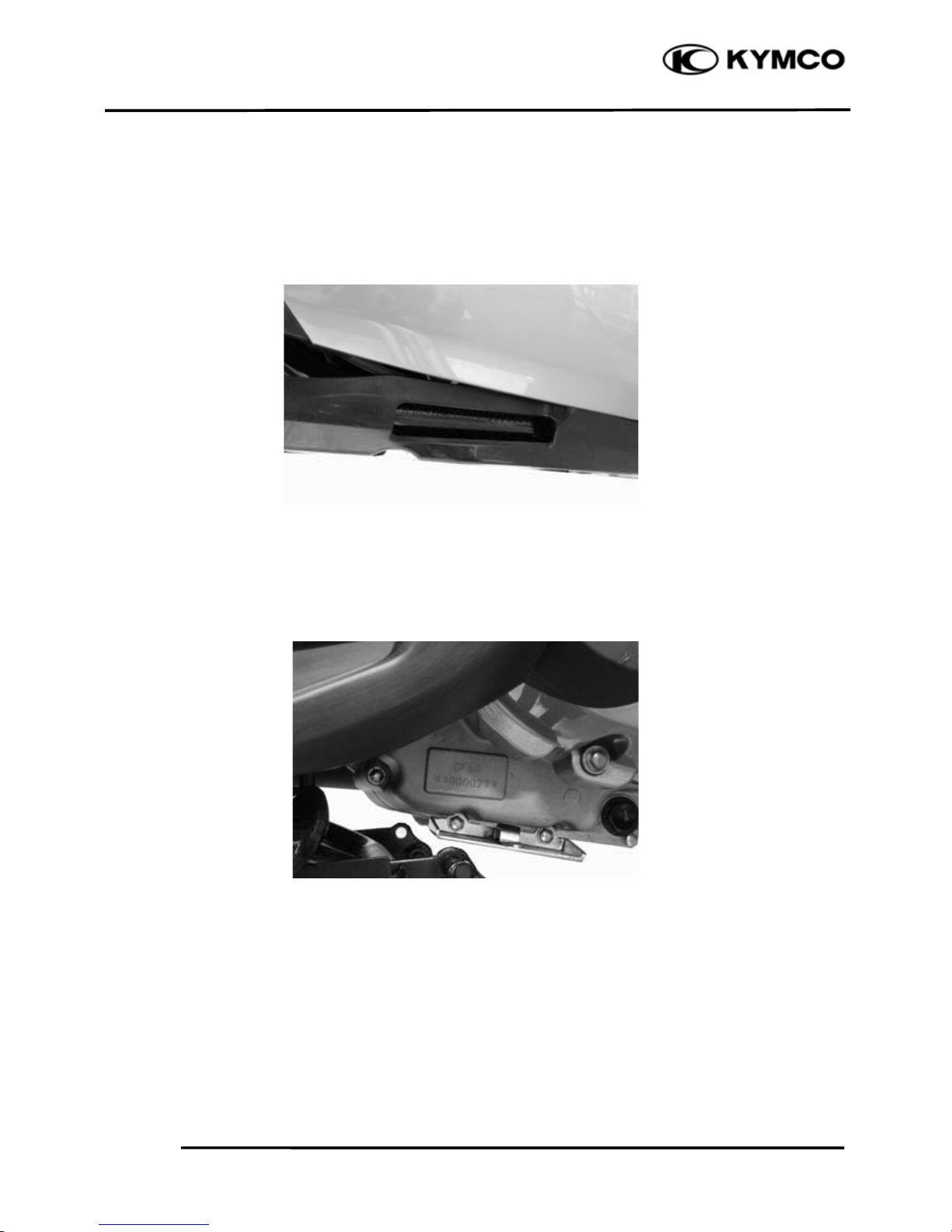
SERIAL NUMBER
Location of Frame Serial Number
Location of Engine Serial Number

1. GENERAL INFORMATION
1-2
People GT 200i
SPECIFICATIONS
Name People GT 200i
Model No. BF40AA
Overall length 2130 mm
Overall width 750 mm
Overall height 1280 mm
Wheel base 1450 mm
Engine type 4 s t r o k e O . H . C .
Displacement 205 cc
Fuel Used 92# nonleaded
gasoline
Front wheel
Rear wheel
Total
171.5
Front wheel
97
Rear wheel
149
Total
246
Ground clearance (mm)
150
Braking distance (m)
7.9m / 40 km/hr
Min. turning radius (mm) R/L
2250/2170
Engine part
Starting system Starting motor
Type
Gasoline 4-cycle
Cylinder arrangement Single cylinde
r
Combustion chamber type Semi-sphere
Valve arrangement O.H.C.-4V
Bore x stroke (mm) φ66 * 60
Compression ratio 10.3:1
Compression pressure
(kg/cm²-rpm)
16-570 rpm
Max. output (ps/rpm) 20.6 / 8000
Max. torque (kg-m/rpm) 2.03 / 6500
Open -5° BTDC
Close 32° BTDC
Open 34° BTDC
Close 5° BTDC
Intake
0.10
Exhaust
0.10
Idle speed (rpm) 1600±100 rpm
Cooling Type Liquid cooling
Lubrication type
Forced pressure &
wet sump
Oil pump type Inner/outer roto
r
Oil filter type Full-flow filtration
Oil capacity 1.5 liter
Exch a n g i n g c a p a c i t y 1.3 liter
Fi injection system
Air cleaner type & No Paper element, wet
Fuel capacity 9 liters
Brand Keihin
Throttle Body
Butterfly type
Venturi diameter (mm)
32
Fuel pump pressure
3.0 bar
Electrical system
Ignition type ECU
Ignition timing
ECU control
Spark plug CR7E (NGK)
Spark plug gap 0.6~0.7mm
Battery Capacity 12V12AH
Transmission system
Clutch type Dry multi-disc
Transmission type
CVT
Operation type Auto centrifugal
Reduction gear type Two-stage reduction
Primary 2.24~0.72
Final 7.222
Moving device
Tire type Tubeless
Front wheel
110/70-16
Rear wheel 140/70-16
Front wheel 1.75
Rear wheel 2.25 (with
passenger)
Wheel material Aluminium
Left 45°±5
Right 45°±5
Front Disk brake
Rear Disk brake
Damping Device
Front
Telescope
Rear Swing arm
Front 110 mm
Shock absorber
stroke
Rear 100 mm
Curb weight
(kg)
Max. weight
(kg)
Intake Timing
Exhaust
Timing
Valve
clearance
Reduction ratio
Tire spec.
Tire pressure
(kg/cm²)
Turning angle
Brake type
Suspension
t
yp
e
1. GENERAL INFORMATION
1-3
People GT 200i
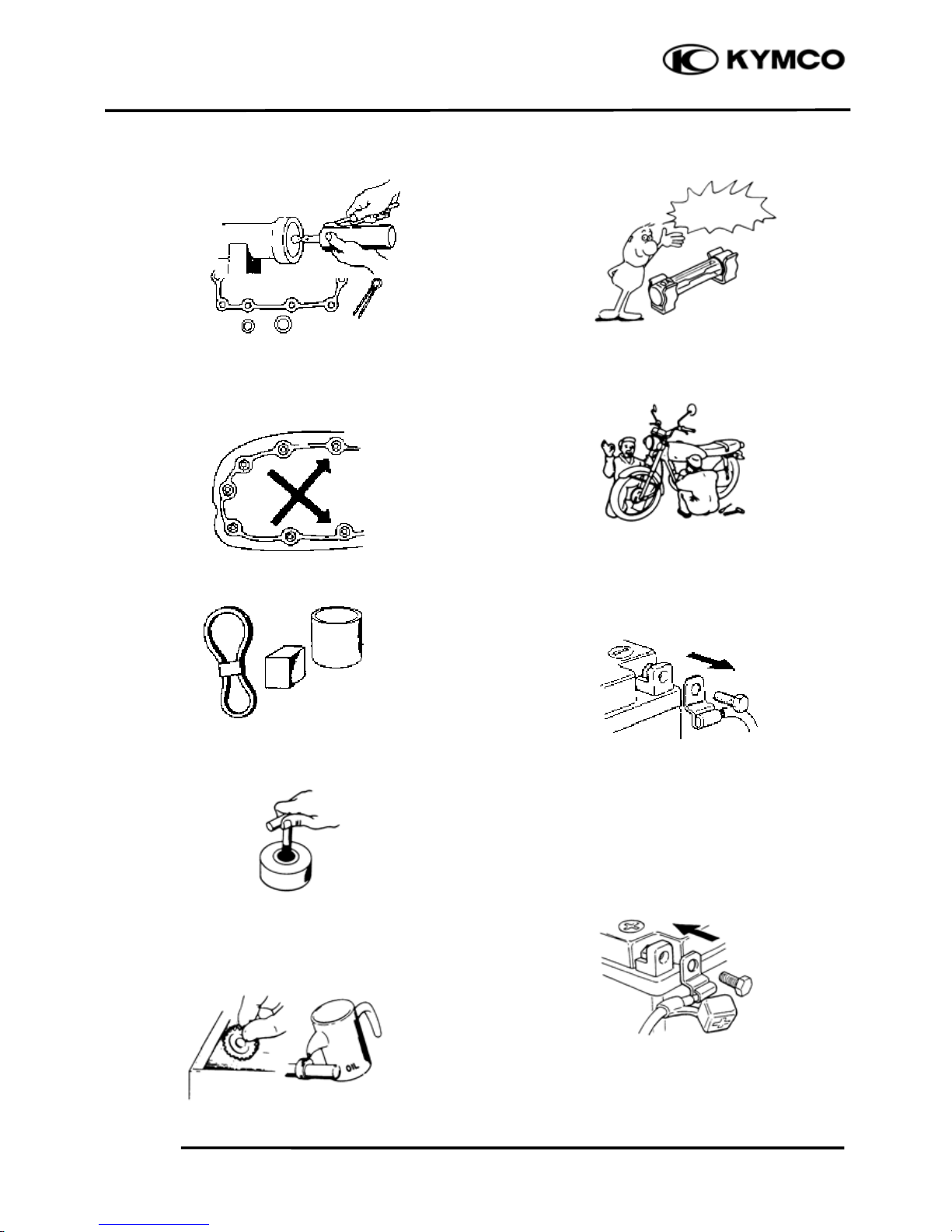
SERVICE PRECAUTIONS
Make sure to install new gaskets, O-rings,
circlips, cotter pins, etc. when
reassembling.
When tightening bolts or nuts, begin with
larger-diameter to smaller ones at several
times, and tighten to the specified torque
diagonally.
Use genuine parts and lubricants.
When servicing the motorcycle, be sure to
use special tools for removal and
installation.
After disassembly, clean removed parts.
Lubricate sliding surfaces with engine oil
before reassembly.
Apply or add designated greases and
lubricants to the specified lubrication points.
When two persons work together, pay
attention to the mutual working safety.
Disconnect the battery negative (-) terminal
before operation.
When using a spanner or other tools,
make
sure not to damage the motorcycle surface.
After operation, check all connecting points,
fasteners, and lines for proper connection
and installation.
When connecting the battery, the positive
(+) terminal must be connected first.
After connection, apply grease to the
battery terminals.
Terminal caps shall be installed securely.
If the fuse
is burned out, find the cause and
repair it. Replace it with a new one
according to the specified capacity.
1. GENERAL INFORMATION
1-4
People GT 200i
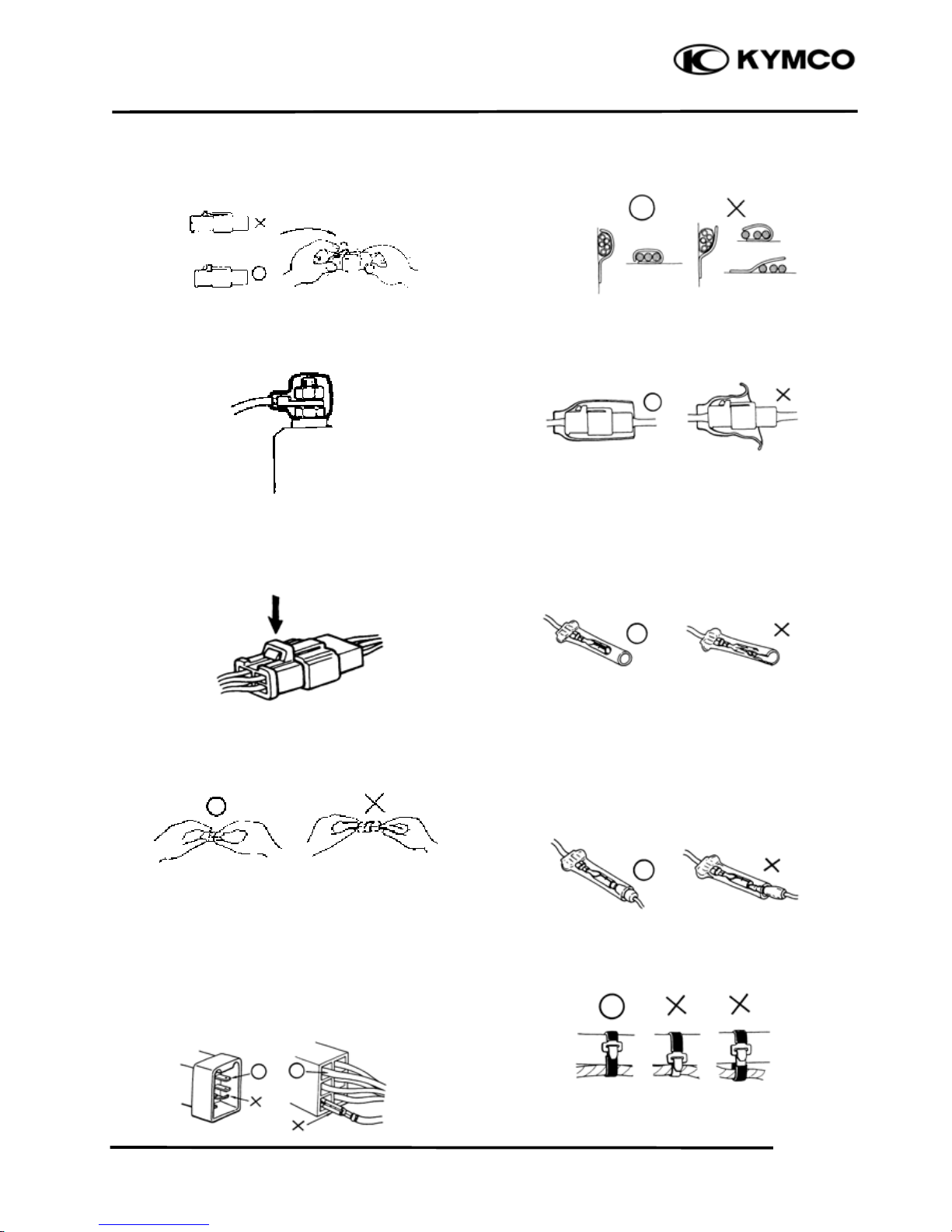
After operation, terminal caps shall be
installed securely.
When taking out the connector, the lock on
the connector shall be released before
operation.
Hold the connector body when
connecting
or disconnecting it.
Do not pull the connector wire.
Check if any connector terminal is
bending,
protruding or loose.
The connector
shall be inserted
completely.
If
the double connector has a lock, lock
it at the correct position.
Check if there is any loose wire.
Before connecting a terminal, check for
damaged
terminal cover or loose negative
terminal.
Check
the double connector cover for
proper coverage and installation.
Insert the terminal completely.
Check the
terminal cover for proper
coverage.
Do
not make the terminal cover opening
face up.
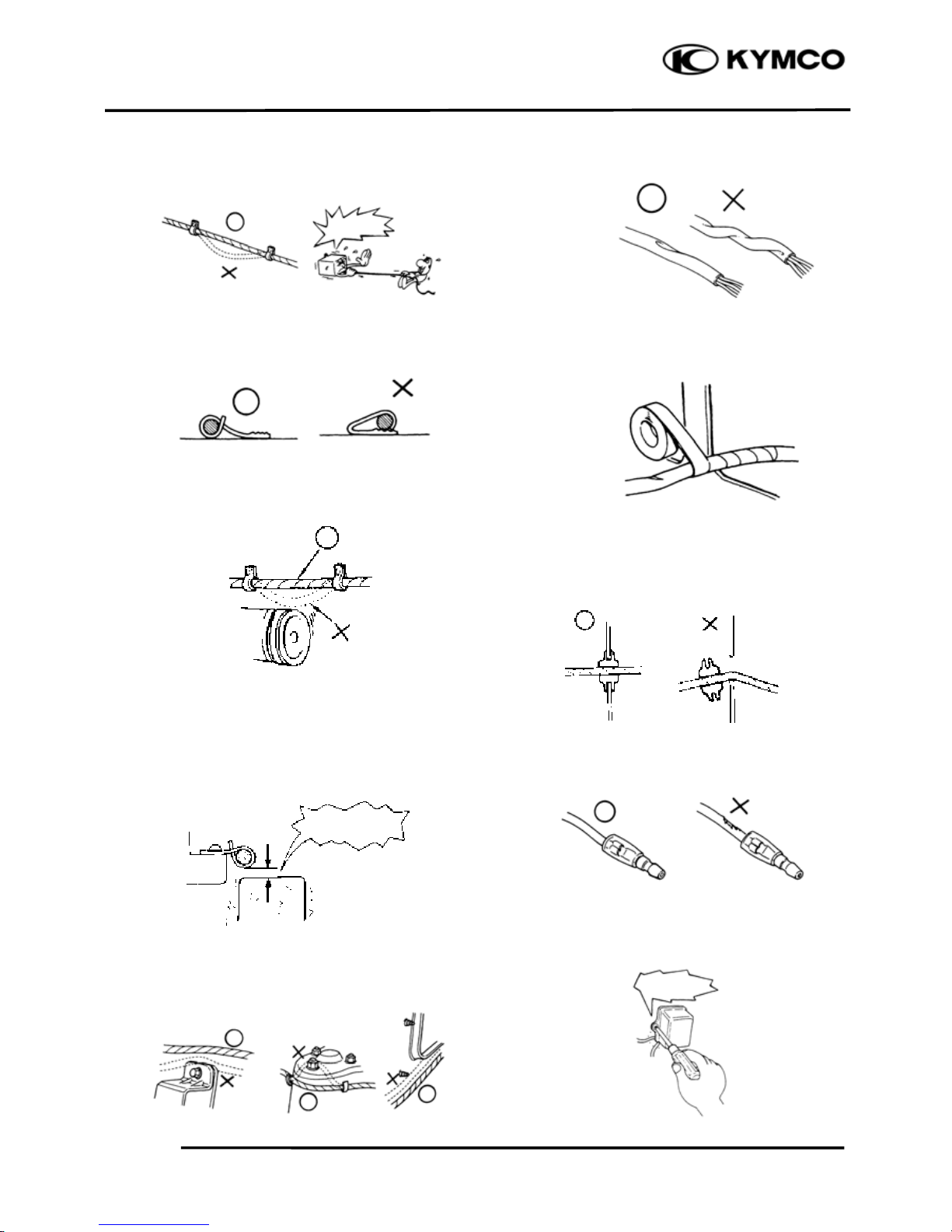
Secure wire harnesses to the frame
with
their respective wire bands at the
designated locations.
Tighten the bands so that only the
insulated
surfaces contact the wire
harnesses.
After
clamping, check each wire to make
sure it is secure.
Confirm
Capacity
1. GENERAL INFORMATION
1-5
People GT 200i
Do not squeeze wires against the weld or
its clamp.
After clamping, check each harness
to
make sure that it is not interfering with any
moving or sliding parts.
When
fixing the wire harnesses, do not
make it contact the parts that will generate
high heat.
Route wire
harnesses to avoid sharp edges
or corners. Avoid the projected ends of
bolts and screws.
Route wire harnesses passing through the
side of bolts and screws. Avoid
the
projected ends of bolts and screws.
Route
harnesses so they are neither
pulled tight nor have excessive slack.
Protect
wires and harnesses with electrical
tape or tube if they contact a sharp edge or
corner.
When rubber protector cover is used to
protect the
wire harnesses, it shall be
installed securely.
Do not break the sheath of wire.
If
a wire or harness is with a broken sheath,
repair by wrapping it with protective tape or
replace it.
When installing other parts, do not press
or
squeeze the wires.
After
routing, check that the wire harnesses
are not twisted or kinked.
Do not pull
too tight!
No Contact
Do not press or
squeeze the wire
1. GENERAL INFORMATION
1-6
People GT 200i
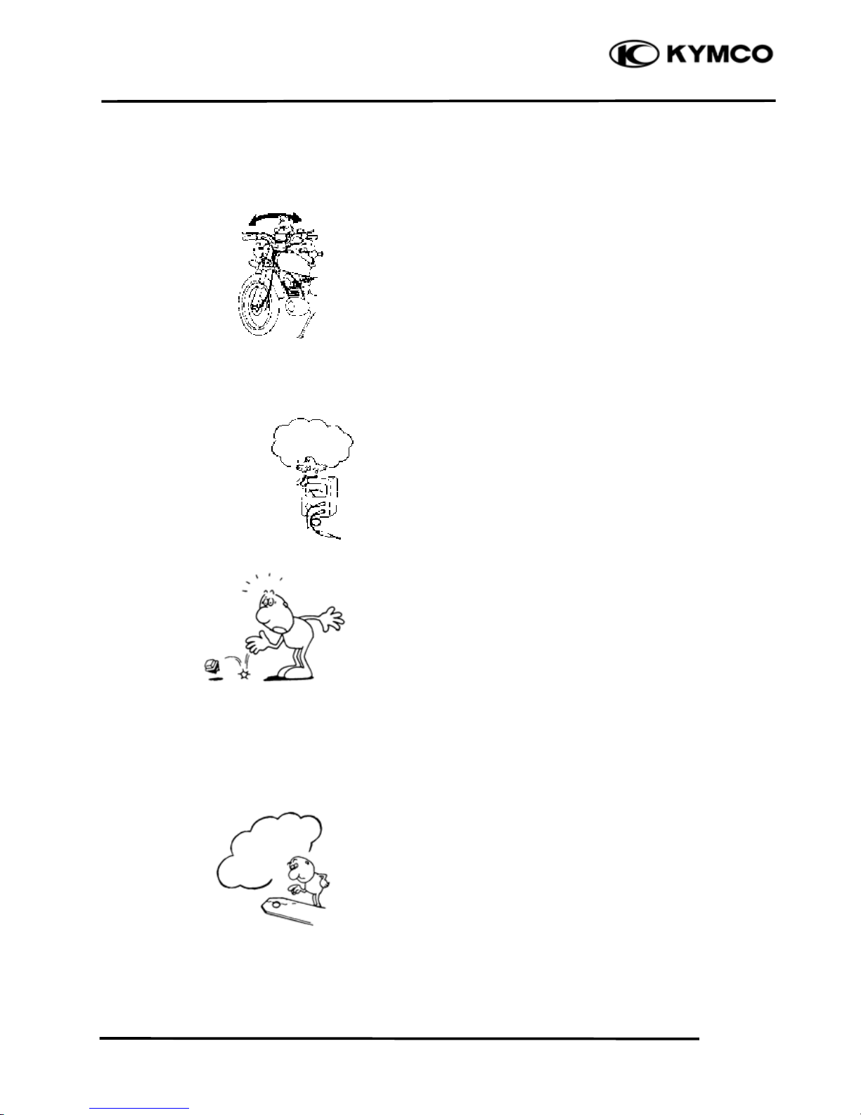
Wire harnesses routed along with
handlebar should not be pulled tight, have
excessive slack or interfere with adjacent
or surrounding parts in all steering
positions.
When
a testing device is used, make sure
to understand the operating methods
thoroughly and operate according to the
operating instructions.
Be careful not to drop any parts.
When rust is found on a terminal, remove
the
rust with sand paper or equivalent
before connecting.
Do you understand
the instrument?
Remove Rust!
1. GENERAL INFORMATION
1-7
People GT 200i
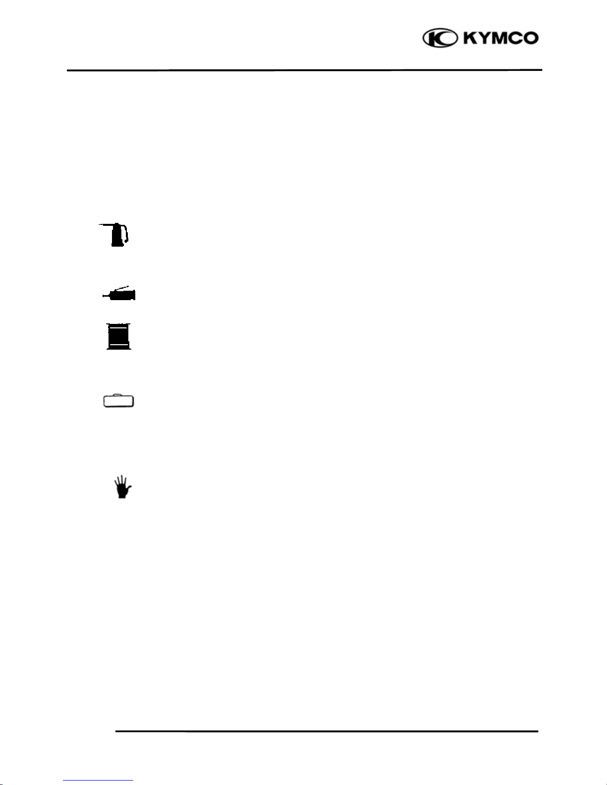
Symbols:
The following symbols represent the
servicing methods and cautions included in
this service manual.
: Apply engine oil to the
specified points. (Use
designated engine oil for
lubrication.)
: Apply grease for lubrication.
: Transmission Gear Oil (90#)
: Use special tool.
: Caution
: Warning
Special
Engine Oil
Grease
Gear Oil
*
1. GENERAL INFORMATION
1-8
People GT 200i
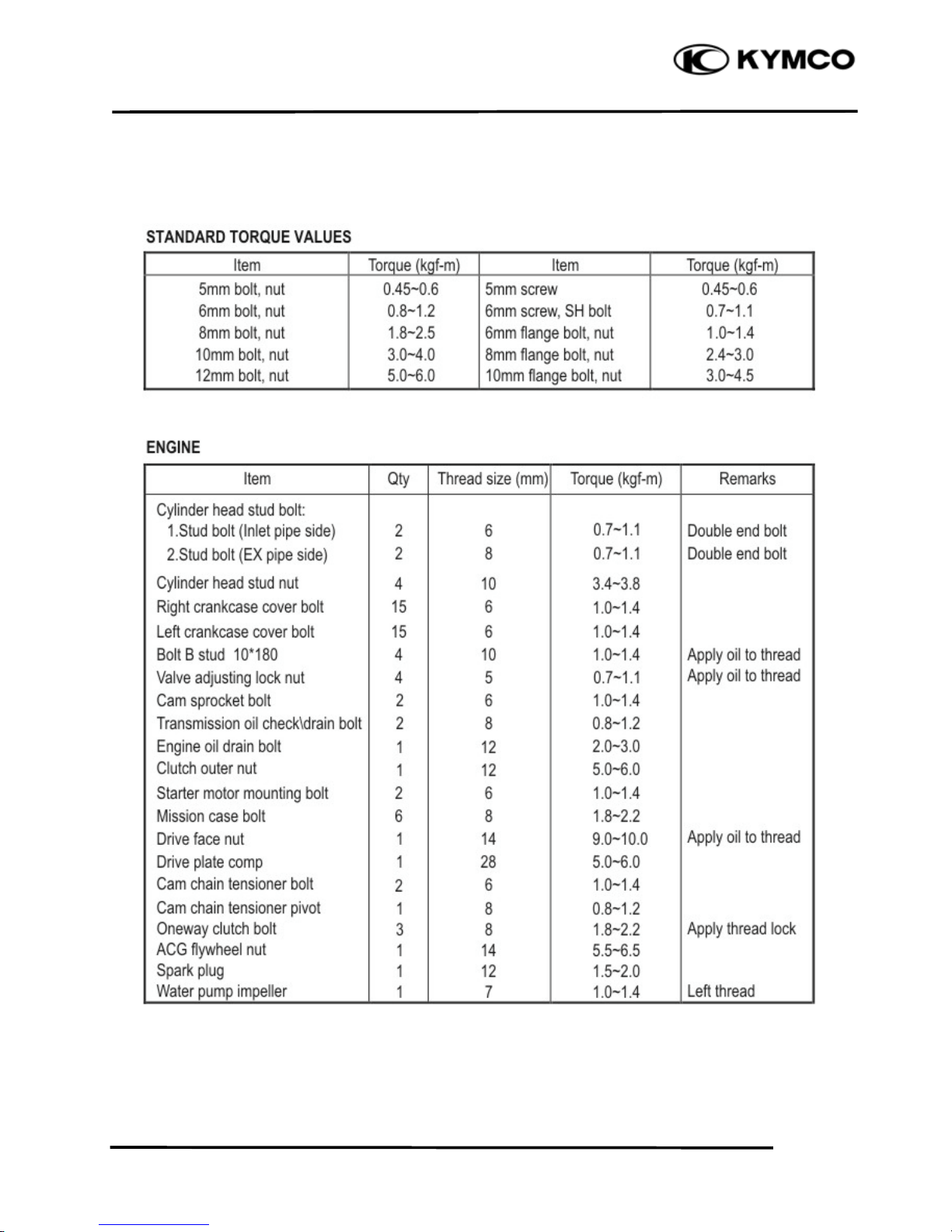
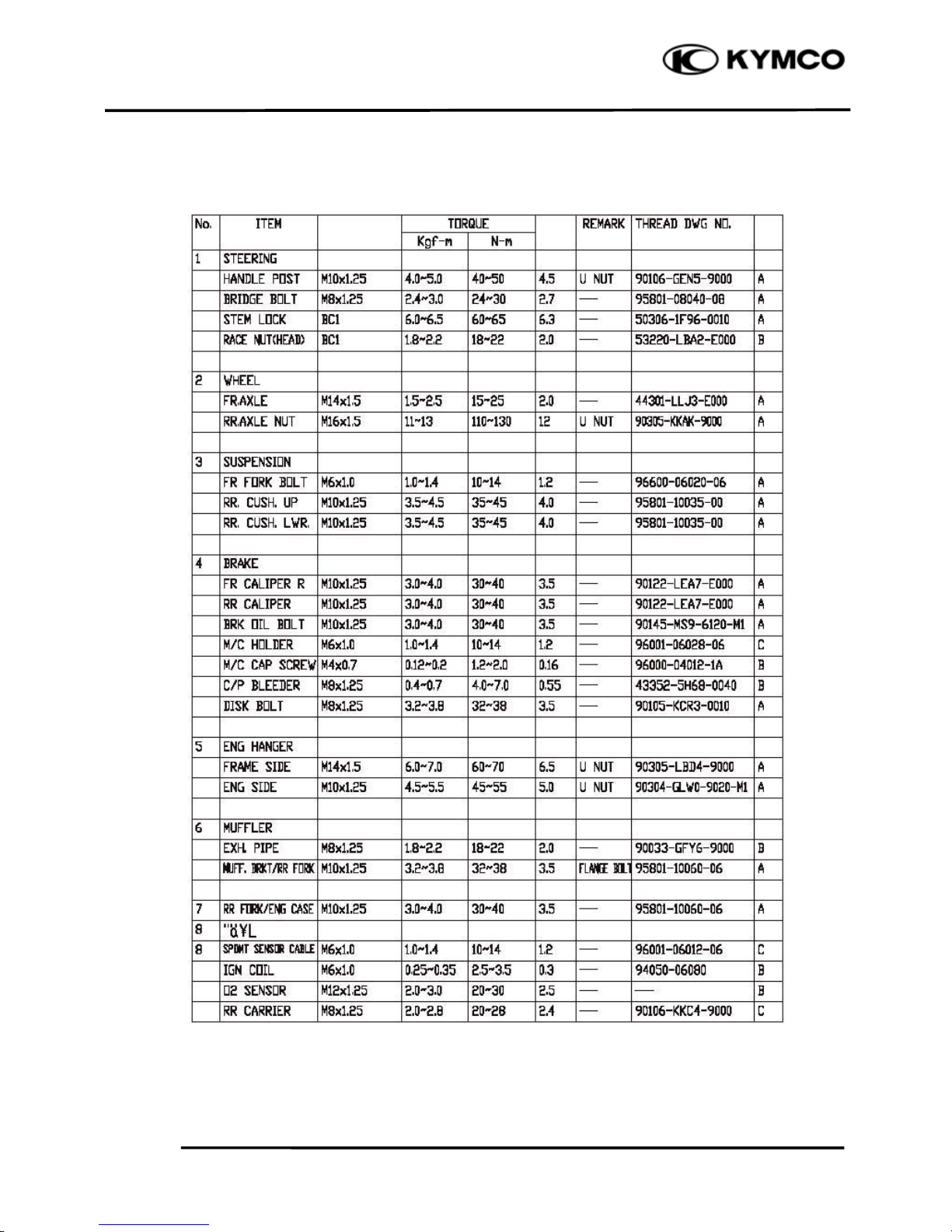
TORQUE VALUES
1. GENERAL INFORMATION
1-9
People GT 200i
TORQUE VALUES
FRAME
1. GENERAL INFORMATION
1-10
People GT 200i
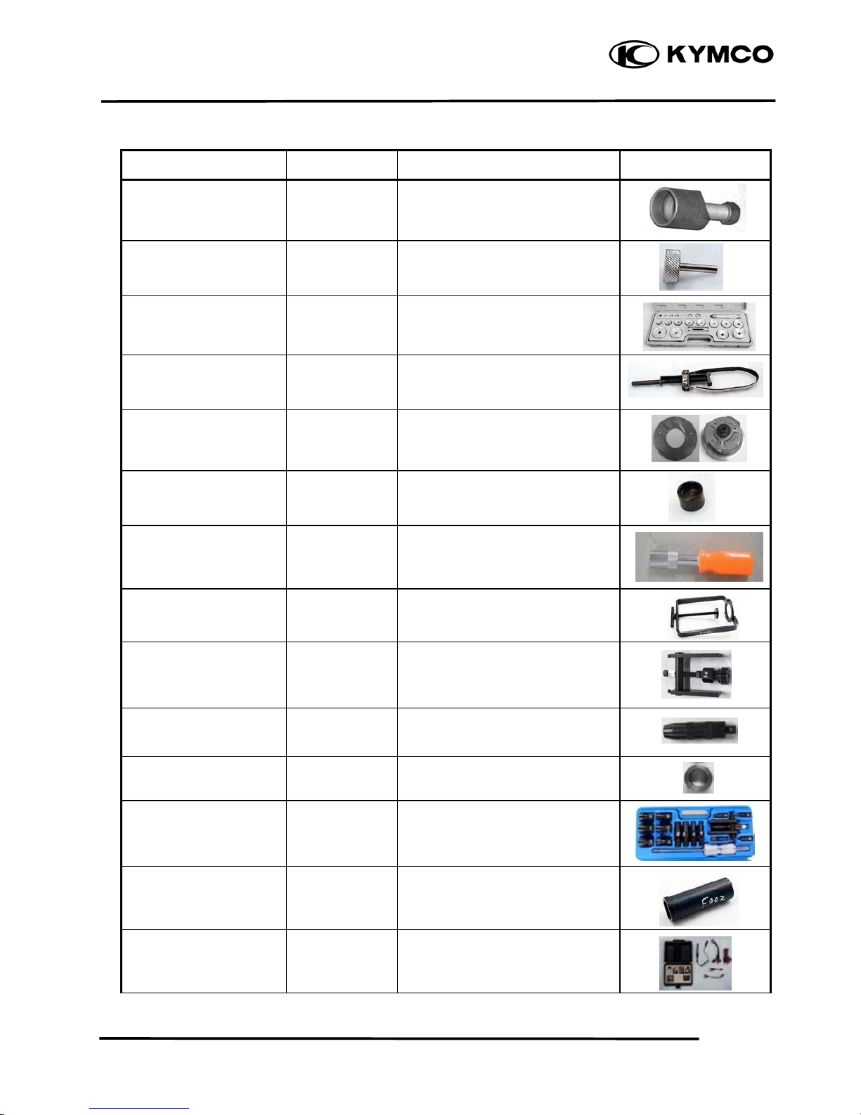
SPECIAL TOOLS
Tool Name Tool No. Performance Photo
Flywheel Puller A120E00003 A.C. generator flywheel removal
Tappet Adjuster A120E00012 Tappet adjustment
Oil Seal & Bearing
Installer
A120E00014 Oil seal & bearing installing
Flywheel Holder A120E00021 A.C. generator flywheel holding
#41 Nut & Fitting A120E00028 Clutch disassembly & assembly
Thread Protector A120E00029 Protecting the crankshaft’s
thread
Valve Cotter Installer A120E00051 Valve cotter installation
Clutch Spring
Compressor
A120E00053 Clutch disassembly & assembly
Shaft Collar Puller A120E00088 Bearing crankcase removal
Shaft Collar Driver A120E00091 Bearing crankcase removal
Shaft Collar Installer A120E00092 Bearing crankcase installation
Bearing Puller A120E00093 Bearing removal
Lock Nut Socket Wrench A120F00002 Steering stem removal or
installation
Electric Repair Kit A120F00032 Fuel injection system diagnosis
1. GENERAL INFORMATION
1-11
People GT 200i
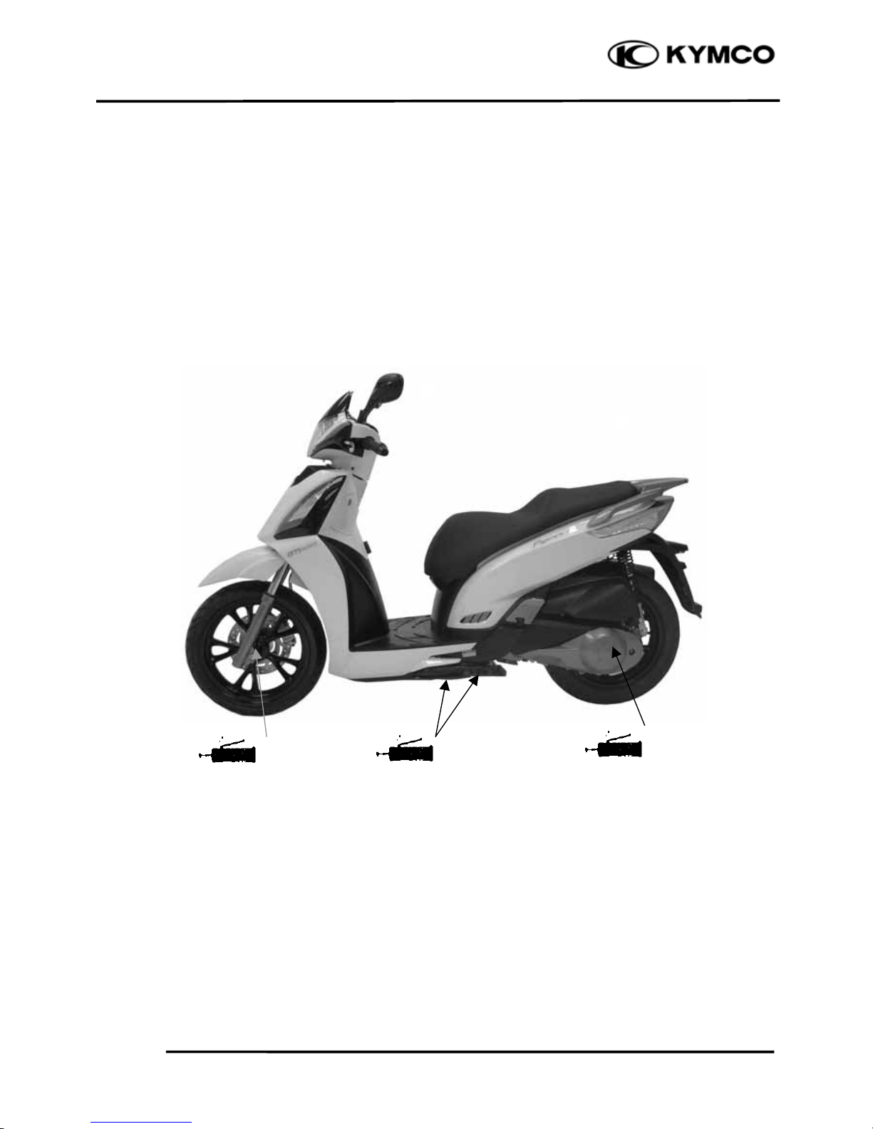
LUBRICATION POINTS
FRAME
The following is the lubrication points for the frame.
Use grease for parts not listed.
Apply engine oil or grease to cables and movable parts not specified. It will avoid abnormal noise
and damage the durability of the motorcycle.
Grease
Grease
Front wheel axle &nut
Rear wheel axle &nut
Grease
Side stand pivot
& Main stand pivot
1. GENERAL INFORMATION
1-12
People GT 200i
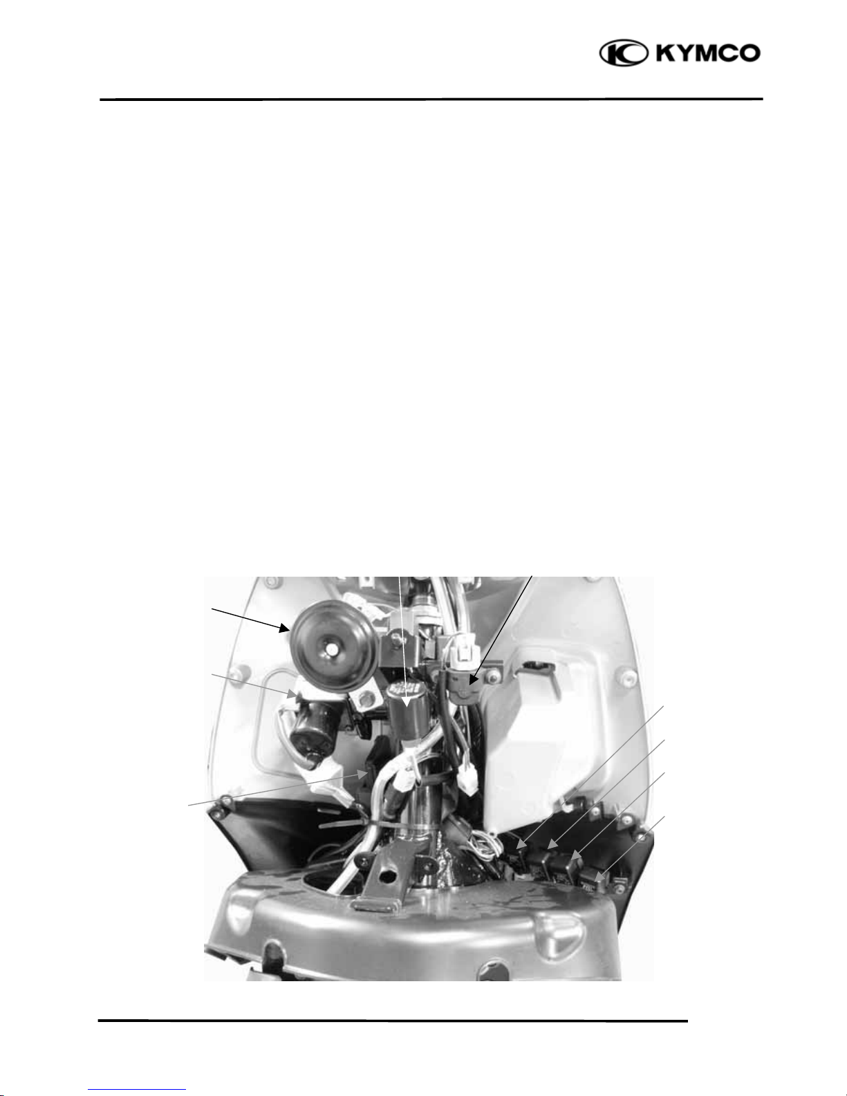
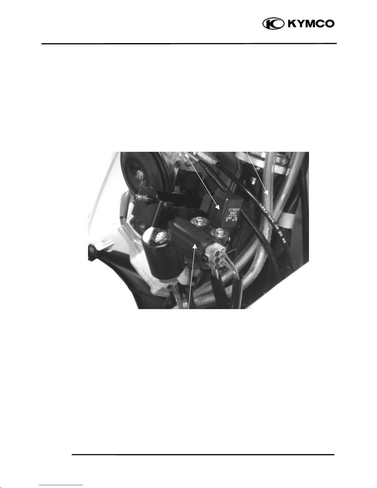
CABLE & HARNESS ROUTING
Tilt Switch
Ignition Switch
ECU
Horn
Winker Relay
Hi Beam Relay
Lo Beam Relay
ECU Relay
Fuel Pump Relay
Tilt Switch
1. GENERAL INFORMATION
1-13
People GT 200i
Oil Controller
Tilt Switch
Front Brake Hose
1. GENERAL INFORMATION
1-14
People GT 200i
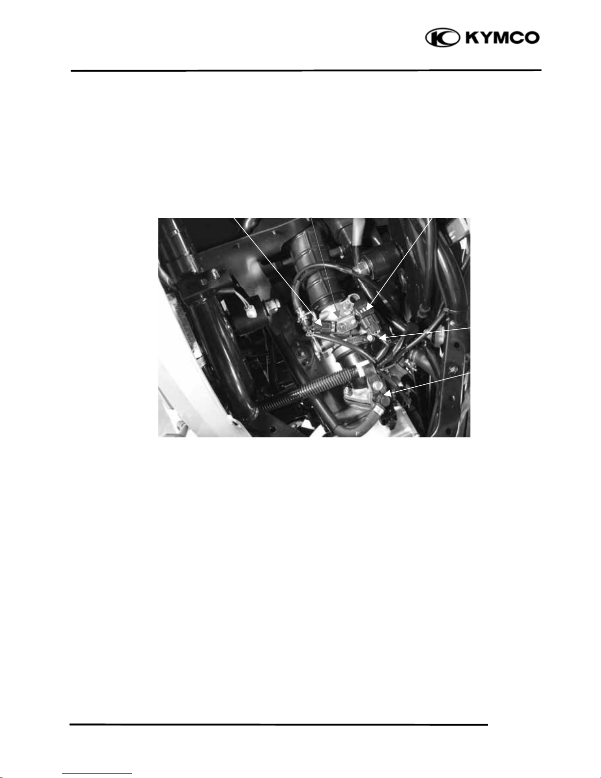
ISCThrottle Body
TPS
Injector
MAP Sensor
1. GENERAL INFORMATION
1-15
People GT 200i
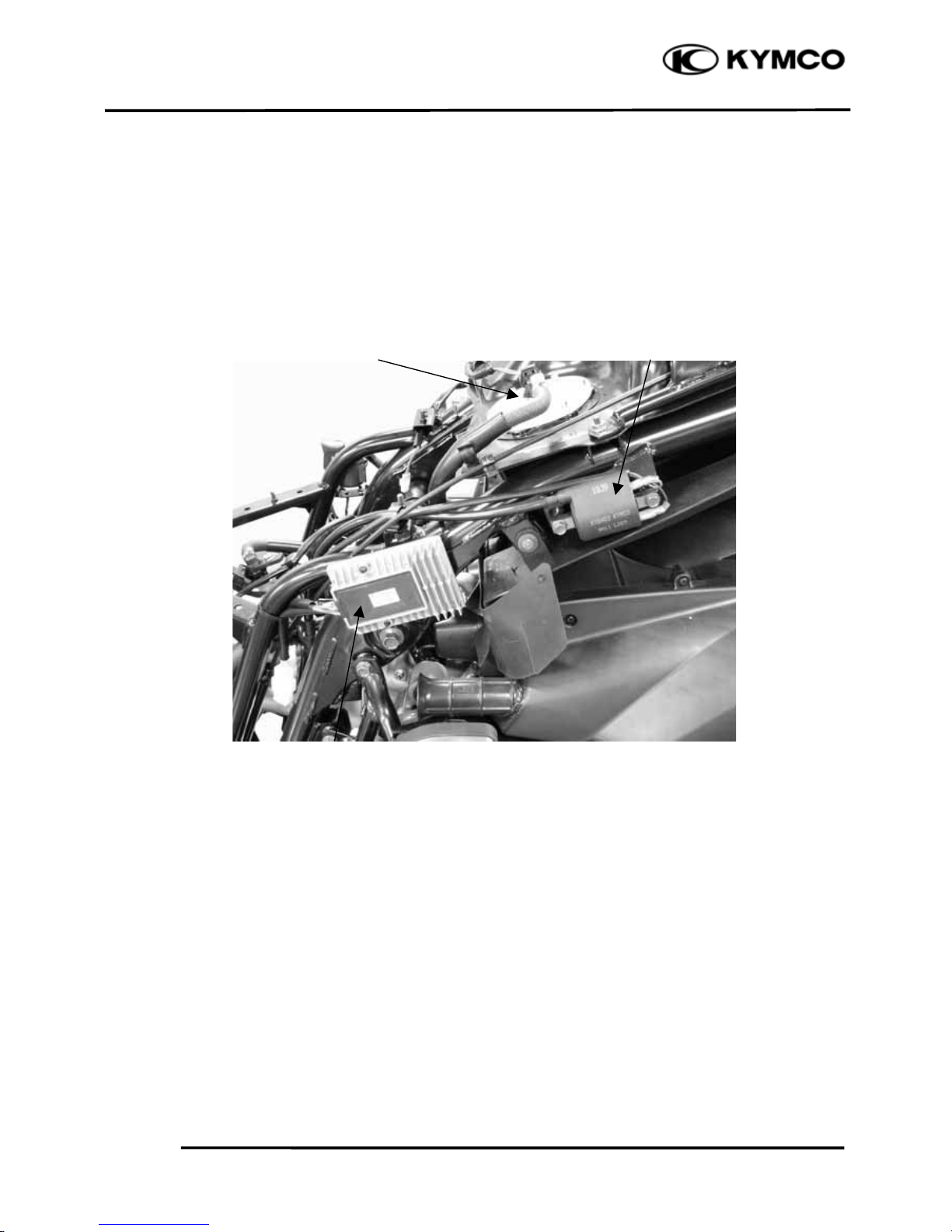
Regulator/Rectifier
Ignition Coil
Fuel Pump

1. GENERAL INFORMATION
1-16
People GT 200i
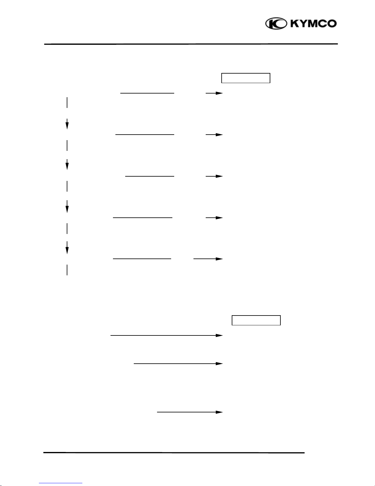
TROUBLESHOOTING
ENGINE WILL NOT START OR IS HARD TO START
Possible cause
1. Check for operation of the fuel pump Abnormal Faulty fuel pump
Normal
2. Inspect the fuel flow Abnormal Faulty pressure regulator
Normal
3. Inspect the fuel injector Abnormal Faulty injector
Normal
4. Perform spark test Weak or no spark Faulty spark plug
Fouled spark plug
Faulty ECU
Good spark Broken or shorted spark plug wire
Faulty ignition switch
Faulty ignition pulse generator
Loose or disconnected spark plug
wire
5. Test cylinder compression Low compression Valve stuck open
Worn cylinder and piston ring
Damaged cylinder head gasket
Compression normal Seized valve
Improper valve timing
6. Starting following normal procedure Engine start Intake pipe leaking
but stops Improper ignition timing (Faulty
ignition coil or ignition pulse
generator)
Engine does not start Fuel contaminated
7. Remove and inspect spark plug Wet plug Throttle valve open
Clogged air cleaner

1. GENERAL INFORMATION
1-17
People GT 200i
ENGINE LACKS POWER
Possible cause
1. Raise wheel off the ground Wheels do not Brake dragging
and spin by hand spin freely Worn or damaged wheel bearing
Wheel spins freely
2. Check tire pressure Pressure low Faulty tire valve
Punctured tire
Pressure normal
3. Accelerate lightly Engine speed does Air cleaner dirty
not increase Restricted fuel flow
Clogged muffler
Engine speed increase Pinched fuel tank breather
4. Check ignition timing Incorrect Faulty ECU
Faulty ignition pulse generator
Correct
5. Test cylinder compression Incorrect Valve stuck open
W
orn cylinder and piston rings
Leaking head gasket
Normal Improper valve timing
6. Inspect fuel flow Abnormal Faulty pressure regulator
Normal
7. Inspect the fuel injector Abnormal Faulty injector
Normal
8. Remove spark plug Fouled or discolored Faulty spark plug
Not fouled or discolored

1. GENERAL INFORMATION
1-18
People GT 200i
Possible cause
9. Check oil level and condition Incorrect Oil level too high
Oil level too low
Contaminated oil
Correct
10. Remove cylinder head cover Valve train not Clogged oil
and inspect lubrication lubricated properly Clogged oil control orifice
Valve train lubricated properly
11. Check for engine overheating Overheating Fan motor not working
Excessive carbon build-up in
combustion chamber
Use of poor quality fuel
Not overheating Wrong type of fuel
Drive and driven pulleys/clutch
slipping
12. Accelerate or run at high Engine knocks Worn piston and cylinder
speed Worn type of fuel
Excessive carbon build-up in
combustion chamber
Ignition timing to advanced (faulty
ECU)
Engine does not knock Lean fuel mixture

1. GENERAL INFORMATION
1-19
People GT 200i
POOR PERFORMANCE AT LOW AND IDLE SPEED
Possible cause
1. Check ignition timing Incorrect Improper ignition timing
Correct
2. Inspect the fuel flow Abnormal Faulty pressure regulator
Normal
3. Inspect the fuel injector Abnormal Faulty injector
Normal
4. Check for leaks in the intake pipe Leaking Loose insulator clamp
Damage insulator
No leak
5. Perform spark test Weak or intermittent spark Faulty the spark plug
Faulty carbon or wet fouled spark
plug
Faulty ECU
Faulty ignition coil
Faulty ignition pulse generator
Faulty ignition switch
Loose or disconnected spark plug
wires
Good spark
1. GENERAL INFORMATION
1-20
People GT 200i
POOR PERFORMANCE AT HIGH SPEED
Possible cause
1. Check ignition timing Incorrect Faulty ECU
Correct
2. Inspect the fuel flow Abnormal Faulty pressure regulator
Normal
3. Inspect the fuel injector Abnormal Faulty injector
Normal
4. Check valve timing Incorrect Camshaft not installed properly
Correct
5. Check valve spring Weak Faulty valve spring
Not weak
POOR HANDLING
Possible cause
1. If steering is heavy Steering stem adjusting nut too
tight
Damaged steering head bearings
2. If either wheel is wobbling Excessive wheel bearing play
Bent rim
Improper installed wheel hub
Swing arm pivot bearing
excessively worn
Bent frame
3. If the motorcycle pulled to one side Faulty the shock absorber
Front and rear wheel not aligned
Bent fork
Bent swing arm
Bent axle

2. EXHAUST MUFFLER/FRAME COVERS
2-0
People GT 200i
2
________________________________________________________________________________
________________________________________________________________________________
________________________________________________________________________________
________________________________________________________________________________
________________________________________________________________________________
EXHAUST MUFFLER/FRAME COVERS
________________________________________________________________________________
SCHEMATIC DRAWING ------------------------------------------------------------------------ 2-1
SERVICE INFORMATION ---------------------------------------------------------------------- 2-2
TROUBLESHOOTING--------------------------------------------------------------------------- 2-2
FRAME COVERS REMOVAL------------------------------------------------------------------ 2-3
EXHAUST MUFFLER REMOVAL ------------------------------------------------------------ 2-6
2
2. EXHAUST MUFFLER/FRAME COVERS
2-1
People GT 200i
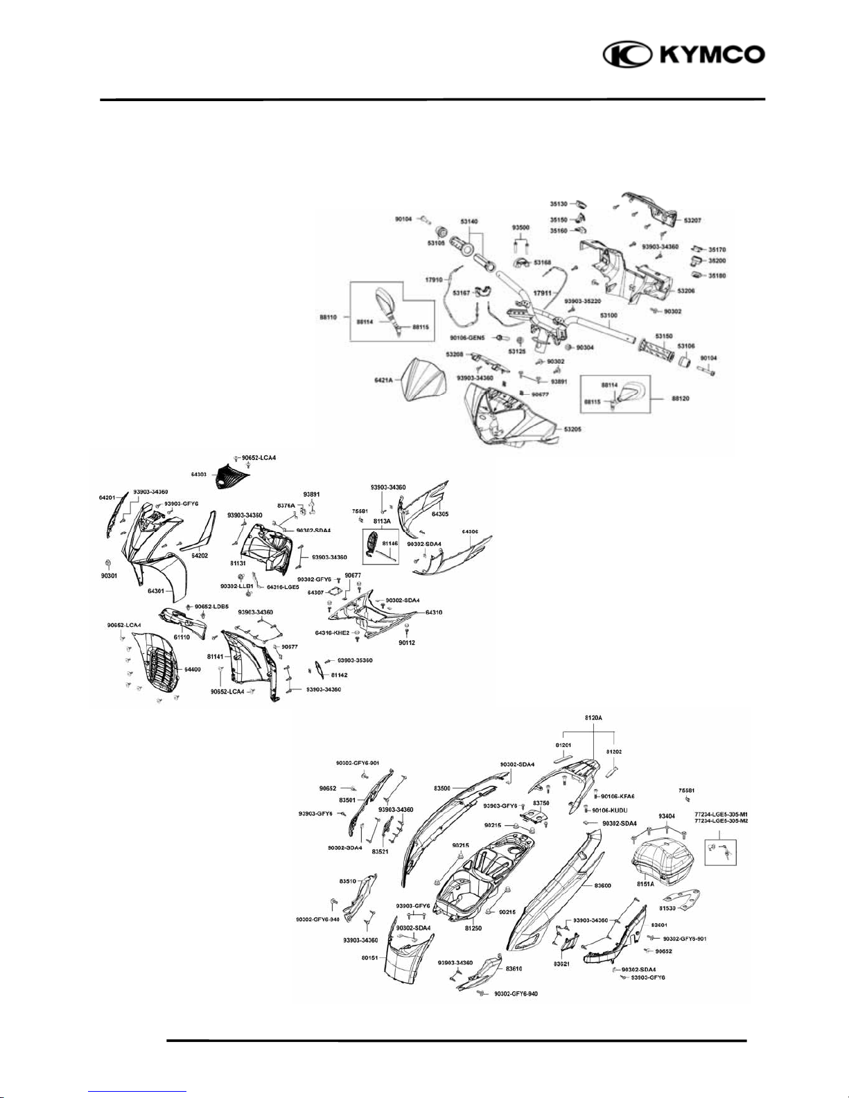
SCHEMATIC DRAWING

2. EXHAUST MUFFLER/FRAME COVERS
2-2
People GT 200i
SERVICE INFORMATION
GENERAL INSTRUCTIONS
• When removing frame covers, use care not to pull them by force because the cover joint claws
may be damaged.
• Make sure to route cables and harnesses according to the Cable & Harness Routing.
TORQUE VALUES
Exhaust muffler lock bolt 35 N-m
Exhaust muffler joint lock nut 20 N-m
TROUBLESHOOTING
Noisy exhaust muffler
• Damaged exhaust muffler
• Exhaust muffler joint air leaks
Lack of power
• Caved exhaust muffler
• Clogged exhaust muffler
• Exhaust muffler air leaks

2. EXHAUST MUFFLER/FRAME COVERS
2-3
People GT 200i
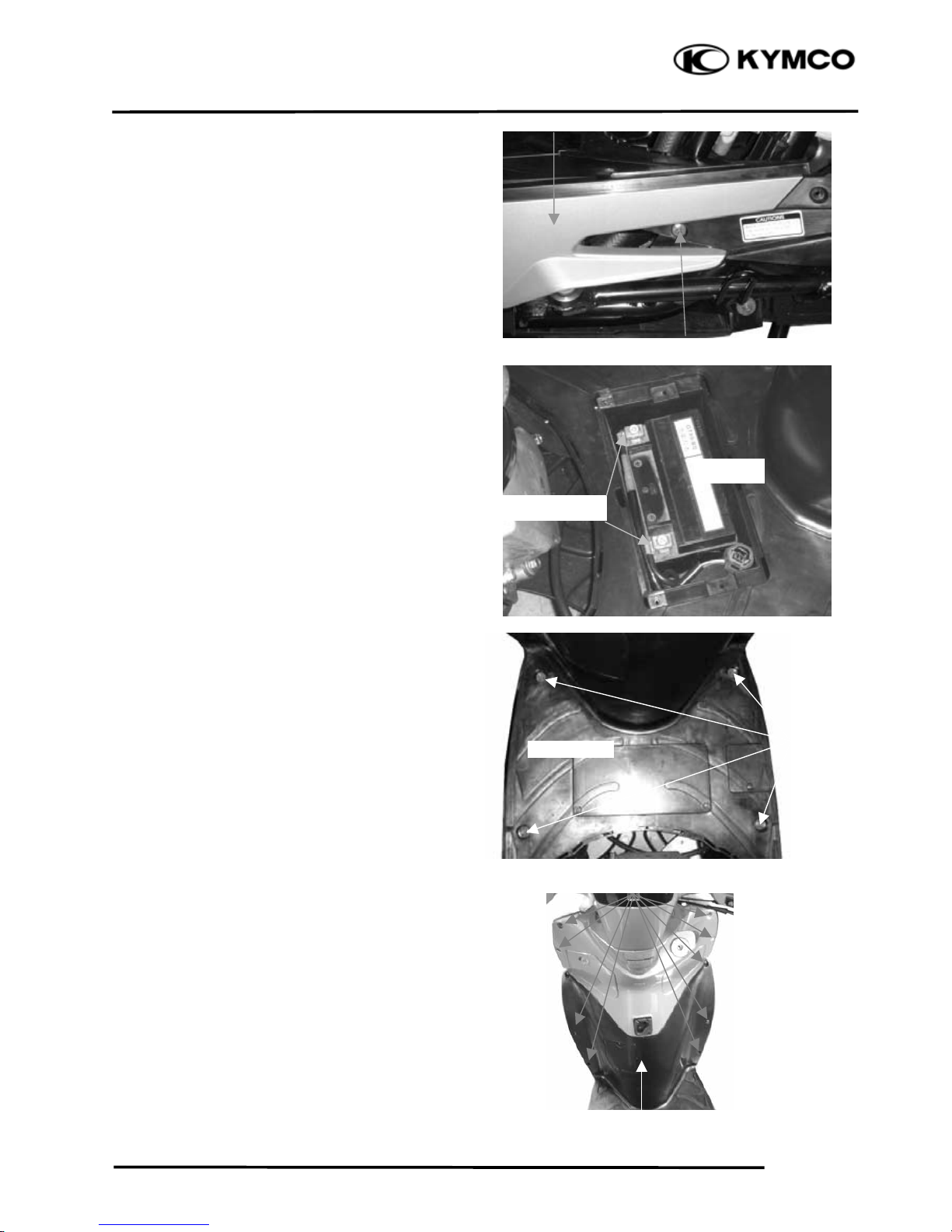
FRAME COVERS REMOVAL
REAR CARRIER
Remove the met-in box.
First remove the eight nuts attaching the metin box.
Remove the met-in box.
Remove the four bolts attaching the rear
carrier.
Remove the rear carrier.
FRAME BODY COVER REMOVAL
Remove the two nuts attaching the rear
protective cover.
Remove the rear protective cover.
Remove the center cover.
Remove the body cover.
Nuts
Carrie
r
Protective Cove
r
Nuts
Body Cove
r
CenterCove
r
2. EXHAUST MUFFLER/FRAME COVERS
2-4
People GT 200i
FLOOR-FOOT REMOVAL
Remove the screws attaching the right and
left side cov
ers.
Remove the right and left side covers by
pulling them outward.
Disconnect the battery wire.
Remove the battery.
Remove the floor mat.
Remove the center cover. (Ö2-3)
Remove the four bolts attaching the
floorboard.
Remove the floorboard.
The installation sequence is the reverse of
removal.
LEG SHIELD REMOVAL
Remove the met-in box.
Remove the body cover.
Remove the floorboard.
Remove the front upper cover.
Remove the screws attaching the leg shield
low.
Disconnect the leg shield low with the cowl
under cover.
The installation sequence is the reverse of
removal.
Screws
Side Cove
r
Bolts
Leg Shield Low
Screws
Battery
Battery Wire
Floorboard
2. EXHAUST MUFFLER/FRAME COVERS
2-5
People GT 200i
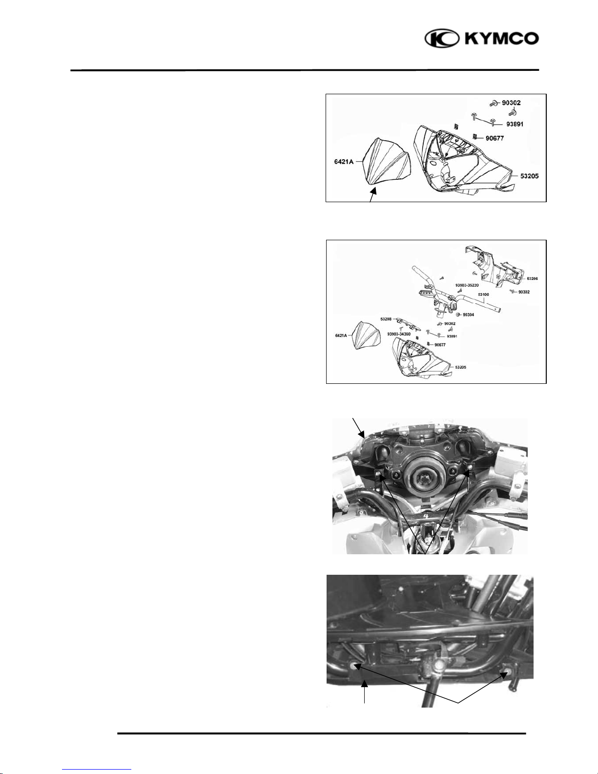
WINDSHIELD REMOVAL
Remove the two bolts attaching the front
windshield.
Remove the windshield cover.
Remove the windshield.
HANDLEBAR COVER REMOVAL
First remove the two bolts attaching the
windshield.
Remove the two screws and four bolts
attaching the handlebar rear cover.
Remove the handlebar rear cover.
The installation sequence is the reverse of
removal.
Remove the two screws attaching the
handlebar cover
Remove the handlebar cover.
The installation sequence is the reverse of
removal.
BOTTOM COVER REMOVAL
Remove the four bolts attaching the bottom
cov
er.
Remove the bottom cover.
Bottom Cove
r
Bolts
Handlebar Cove
r
Screws
Windshield
2. EXHAUST MUFFLER/FRAME COVERS
2-6
People GT 200i
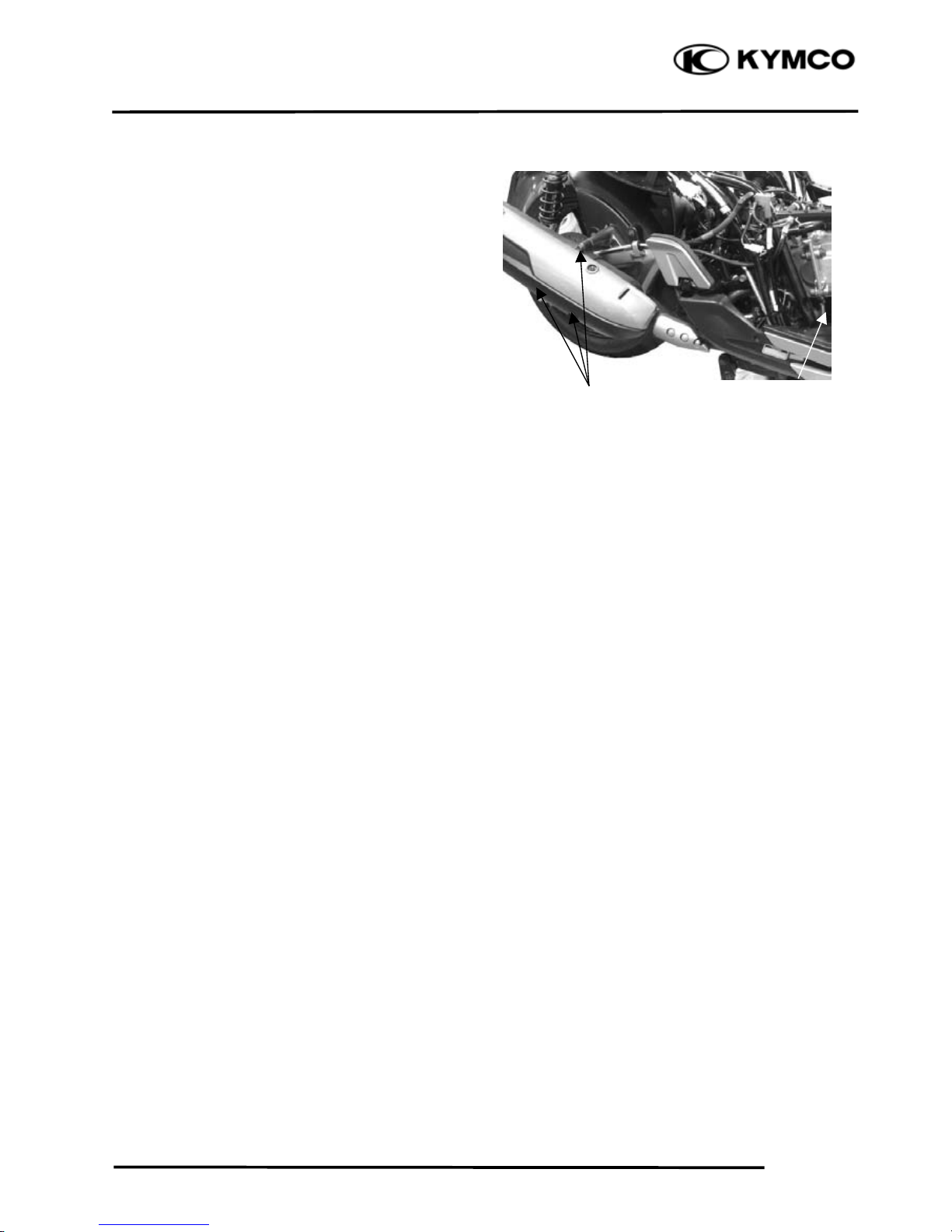
EXHAUST MUFFLER REMOVAL
Remove three lock nuts from joint in the
exhaust muffler.
Remove the exhaust muffler two lock bolts to
remove the exhaust muffler.
Remove the exhaust muffler joint packing
collar.
The installation sequence is the reverse of
removal.
Torque:
Exhaust muffler lock bolt 35 N-m
Exhaust muffler joint lock nut 20 N-m
Lock Bolts
Lock Nut
 Loading...