

Page 1
PREFACE
This Service Manual describes the
technical features and servicing
procedures for the KYMCO
Mongoose/KXR 250.
Section 1 contains the precautions for
all operations stated in this manual.
Read them carefully before starting any
operation.
Section 2 is the removal/installation
procedures for the frame covers which
are subject to higher removal/installation
frequency during maintenance and
servicing operations.
Section 3 describes the inspection/
adjustment procedures, safety rules and
service information for each part,
starting from periodic maintenance.
Sections 4 through 19 give instructions
for disassembly, assembly and
inspection of engine, chassis frame and
electrical equipment.
Most sections start with an assembly or
system illustration and troubleshooting
for the section. The subsequent pages
give detailed procedures for the section.
KWANG YANG MOTOR CO., LTD.
OVERSEAS SALES DEPARTMENT
OVERSEAS SERVICE SECTION
TABLE OF CONTENTS
GENERAL INFORMATION 1
FRAME COVERS/EXHAUST MUFFLER 2
INSPECTION/ADJUSTMENT 3
LUBRICATION SYSTEM 4
FUEL SYSTEM 5
ENGINE REMOVAL 6
CYLINDER HEAD/VALVES 7
CYLINDER/PISTON 8
DRIVE AND DRIVEN PULLEYS
9
FINAL REDUCTION/TRANSMISSION
SYSTEM
10
CRANKCASE/CRANKSHAFT/
BALANCE SHAFT
11
COOLING SYSTEM
12
BRAKE SYSTEM
13
FRONT WHEEL/FRONT
SUSPENSION/STEERING SYSTEM
14
REAR WHEEL/AXLE/SUSPENSION
15
BATTERY/CHARGING SYSTEM/A.C.
GENERATOR
16
IGNITION SYSTEM 17
STARTING SYSTEM 18
BULBSREMOVAL/INSTRUMENT/
HORN
19
The information and contents include
d
in this manual may be different from
the motorcycle in case specifications
are changed.
CHASSIS
ELECTRICAL
EQUIPMENT
ENGINE
Page 2

1. GENERAL INFORMATION
1-0
Mongoose/KXR 250
1
__________________________________________________________________________________
__________________________________________________________________________________
__________________________________________________________________________________
__________________________________________________________________________________
__________________________________________________________________________________
GENERAL INFORMATION
__________________________________________________________________________________
SERIAL NUMBER---------------------------------------------------------- 1- 1
SPECIFICATIONS---------------------------------------------------------- 1- 2
SERVICE PRECAUTIONS------------------------------------------------ 1- 3
TORQUE VALUES --------------------------------------------------------- 1-11
SPECIAL TOOLS ----------------------------------------------------------- 1-12
LUBRICATION POINTS -------------------------------------------------- 1-13
CABLE & HARNESS ROUTING ---------------------------------------- 1-16
WIRING DIAGRAM-------------------------------------------------------- 1-19
TROUBLESHOOTING----------------------------------------------------- 1-21
1
Page 3
1. GENERAL INFORMATION
1-1
Mongoose/KXR 250
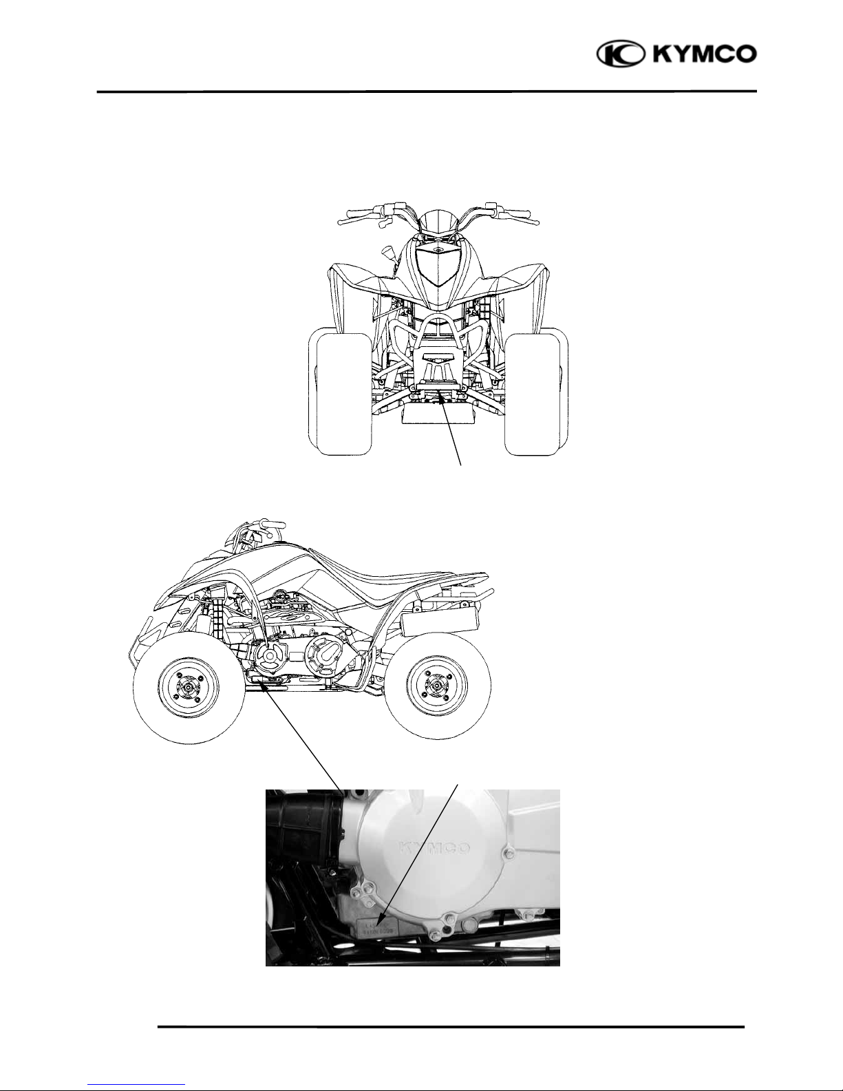
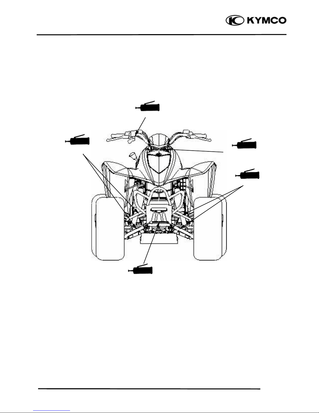
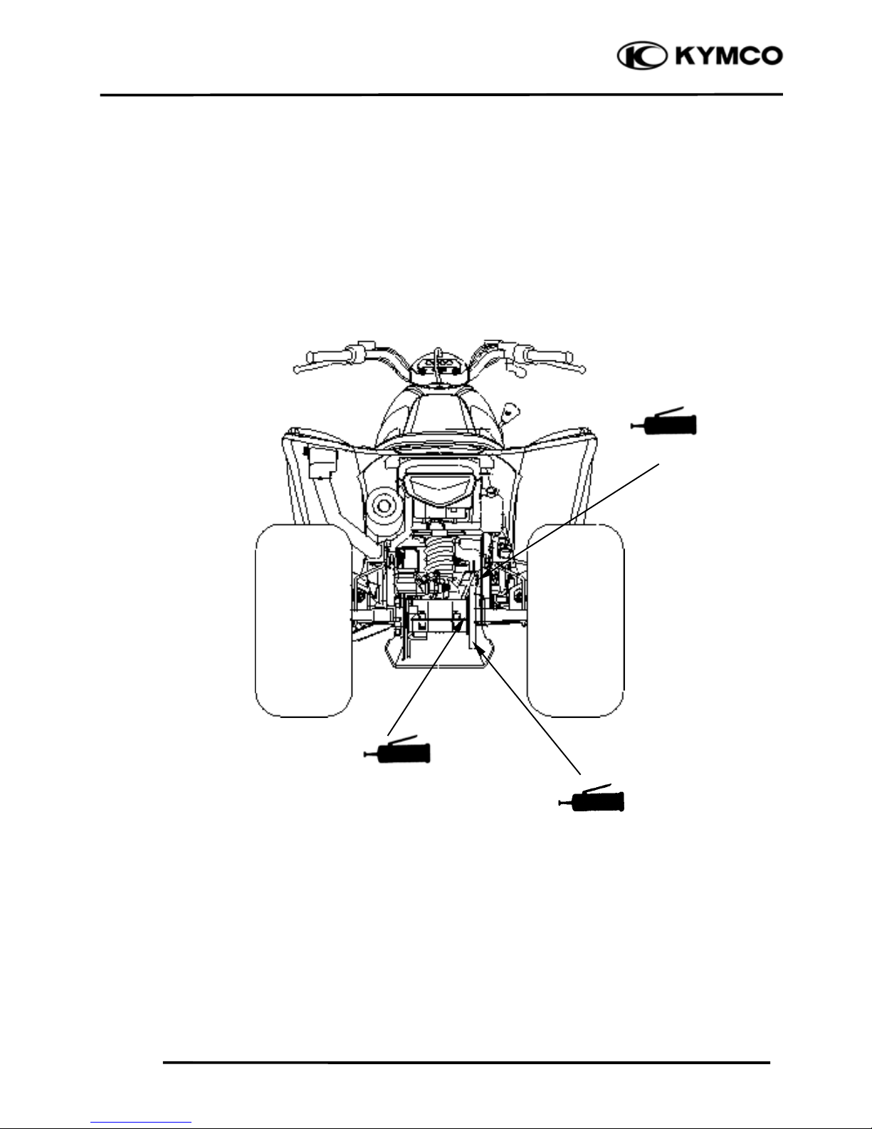
SERIAL NUMBER
Location of Engine Serial Numbe
r
Location of Frame Serial Numbe
r
Page 4
1. GENERAL INFORMATION
1-2
Mongoose/KXR 250
SPECIFICATIONS
Name & Model No. LA50AA/AB
Motorcycle Name & Type Mongoose/KXR
Overall length (mm) 1700
Overall width (mm) 1070
Overall height (mm) 1080
Wheel base (mm) 1180
Engine type O.H.C.
Displacement (cc) 249
Fuel Used 92# nonleaded gasoline
Front wheel 93.1
Net weight (kg) Rear wheel 84.9
Total 178
Front wheel 100
Gross weight(kg) Rear wheel 91
Total 191
Front wheel 21*7-10
Rear wheel 20*11-9
Ground clearance (mm) 130
Perform-
Breakin
g
distance
(m)(30KPH)
29.27 below
ance
Min. turning radius (m) 2.865
Starting system
Starting motor
Type Gasoline, 4-stroke
Cylinder arrangement Single cylinder
Combustion chamber type Semi-sphere
Valve arrangement O.H.C., chain drive
Bore x stroke (mm) 72.7 x 60
Compression ratio 10.3:1
Compression pressure
(kg/cm²)
15.0
Max. output (ps/rpm) 17/7000
Max. torque (kg m/rpm) 2.0/5500
Intake
Open 8.1° BTDC
Port
(1mm)
Close 41° ABDC
timin
g
Exhaust
Open 37° BBDC
(1mm)
Close 7.9° ATDC
Valve clearance
Intake 0.1
(cold) (mm)
Exhaust 0.1
Idle speed (rpm) 1500rpm
Lubrication type
Forced
p
ressure &
Wet sump
Oil pump type Inner/outer rotor type
Oil filter type Full-flow filtration
Oil capacity 1.6 liter
Oil exchanging
capacity
1.4 liter
Cooling Type Water cooling
Air cleaner type & No Sponge
Fuel capacity 13 liters
Type PD
Float lever 14.8mm
Venturi dia.(mm) φ22
Throttle type PISTON
Type CDI
Ignition timing 5°BTDC/2000rpm
Contact breaker Non-contact point type
Spark plug DPR7EA-9
Spark plug gap 0.6~0.7mm
Battery Capacity 12V12AH
Clutch Type CVT
Type Helical gear/spur gear
Operation
Automatic centrifugal
Type
Type Chain drive
Reduction 1st
24.7
ratio
2nd
9.33
Reverse ratio
47.4
FR/RR tire rolling
circumference(mm)
1675/1596
Tire pressure
Fron
t
0.28
(kg/cm²)
Rear 0.28
Turning Left 40°
angle
Right 40°
Brake syste
m
Rea
r
Disk brake
type
Front Disk brake
Front
Double wishbone
Suspension
type
Rear
Link suspension
Frame type Steel tube frame
Tires
Engine
Lubrication
S
y
stem
Fuel S
y
stem
Carbureto
r
Electrical Equipment
I
g
nition S
y
stem
Power Drive System
Transmis-
sion Gear
Reduction
Gear
Moving Device
Damping
Device
Page 5
1. GENERAL INFORMATION
1-3
Mongoose/KXR 250
SERVICE PRECAUTIONS
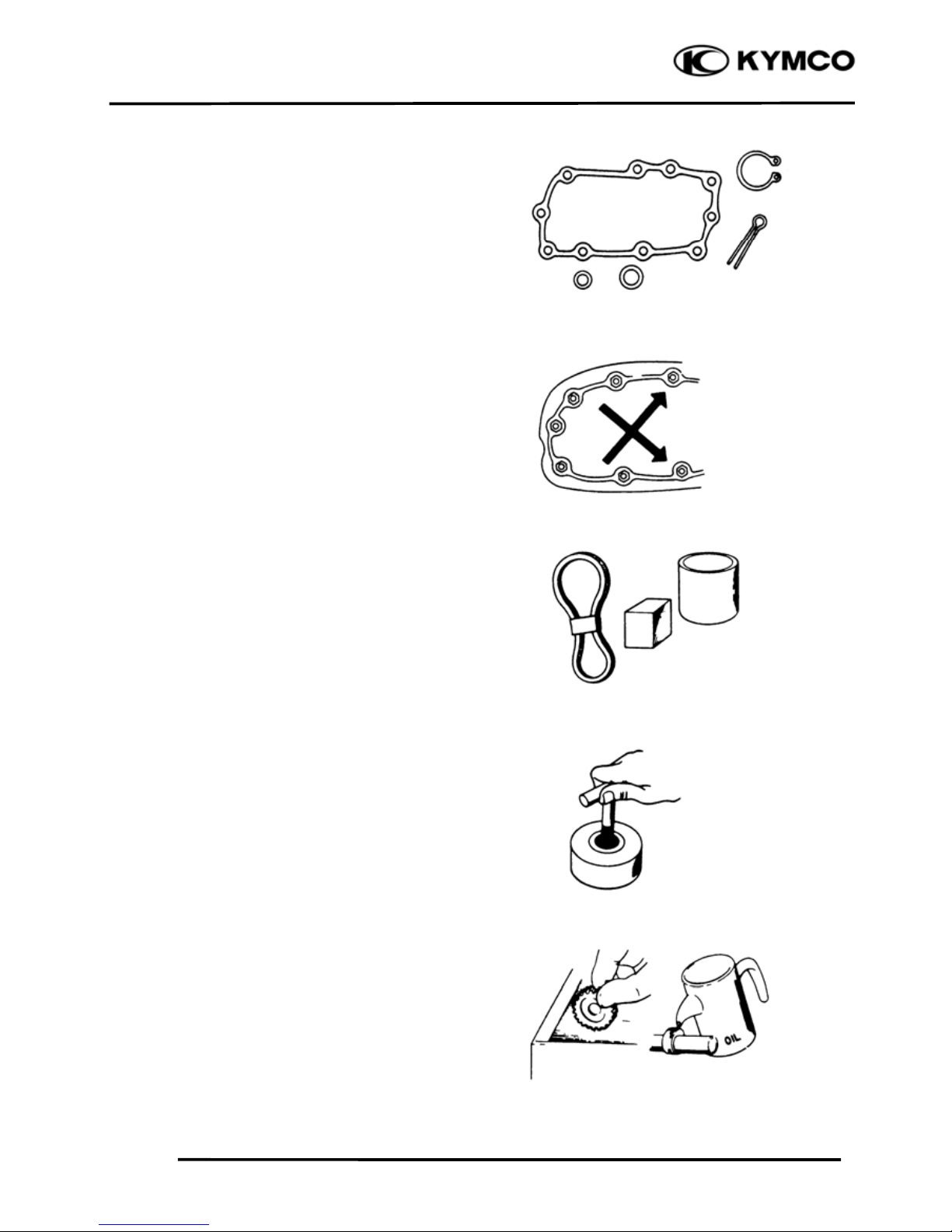
Make sure to install new gaskets, O-rings,
circlips, cotter pins, etc. when
reassembling.
When tightening bolts or nuts, begin with
larger-diameter to smaller ones at several
times, and tighten to the specified torque
diagonally.
Use genuine parts and lubricants.
When servicing the motorcycle, be sure
to use special tools for removal and
installation.
After disassembly, clean removed parts.
Lubricate sliding surfaces with engine oil
before reassembly.
Page 6
1. GENERAL INFORMATION
1-4
Mongoose/KXR 250
Apply or add designated greases and
lubricants to the specified lubrication
points.
After reassembly, check all parts for
proper tightening and operation.
When two persons work together, pay
attention to the mutual working safety.
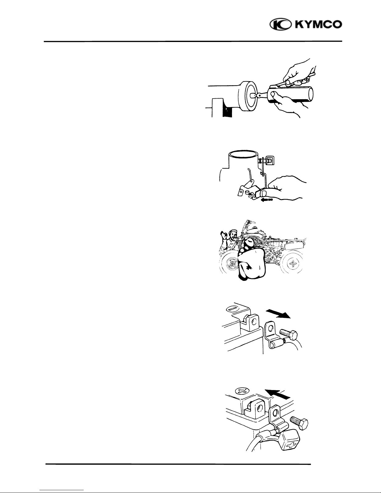
Disconnect the battery negative (-)
terminal before operation.
When using a spanner or other tools,
make sure not to damage the motorcycle
surface.
After operation, check all connecting
points, fasteners, and lines for proper
connection and installation.
When connecting the battery, the positive
(+) terminal must be connected first.
After connection, apply grease to the
battery terminals.
Terminal caps shall be installed securely.
Page 7
1. GENERAL INFORMATION
1-5
Mongoose/KXR 250
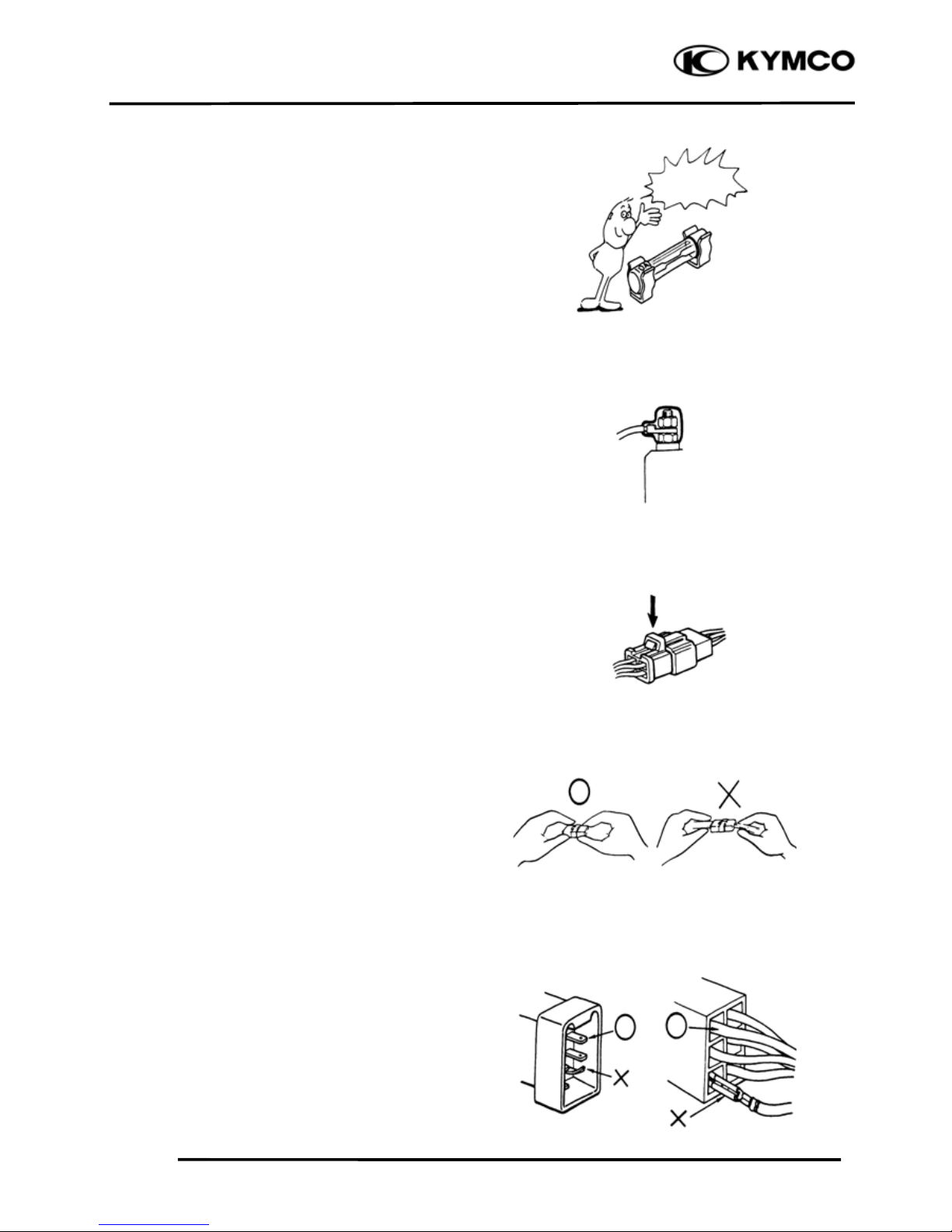
If the fuse is burned out, find the cause
and repair it. Replace it with a new one
according to the specified capacity.
After operation, terminal caps shall be
installed securely.
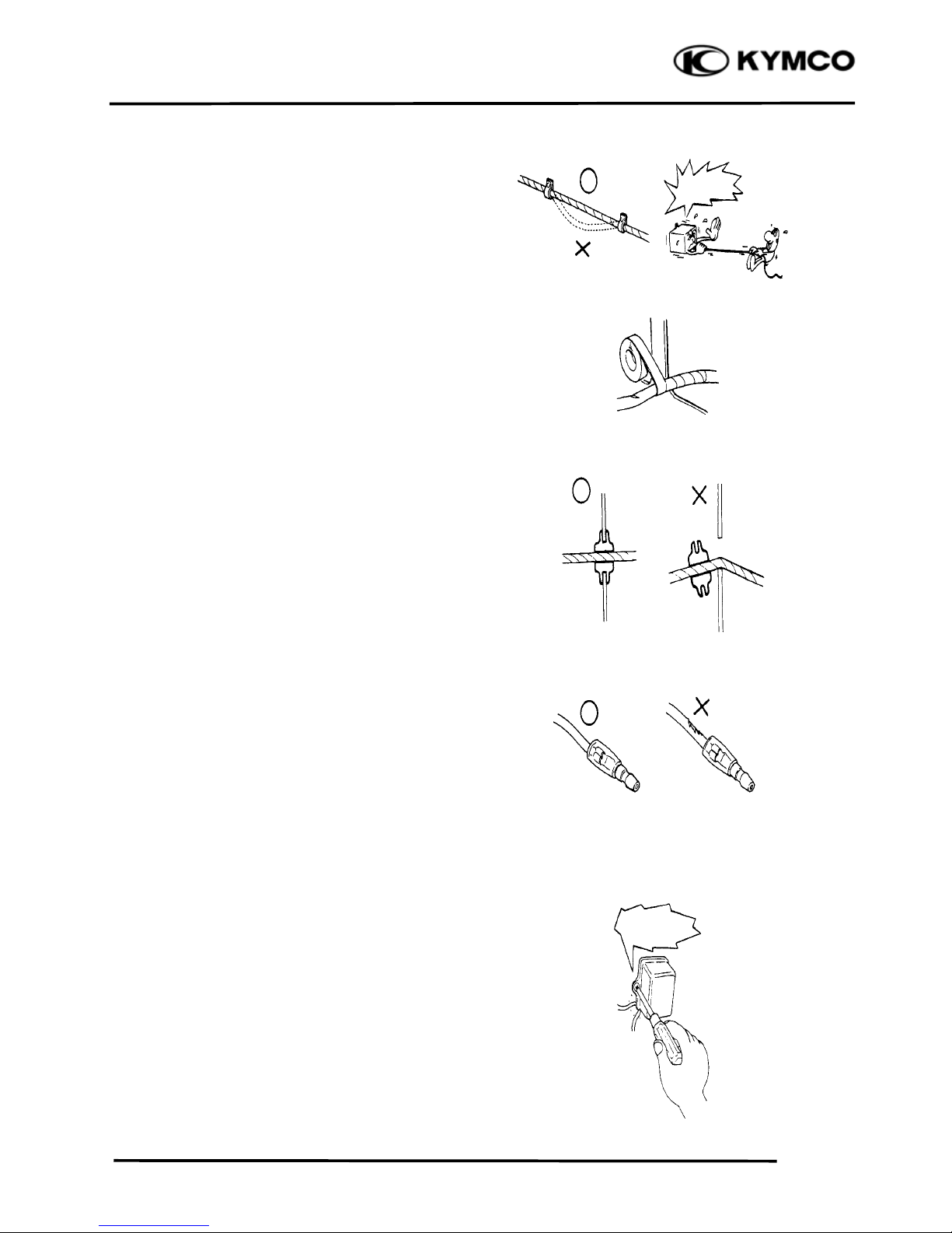
When taking out the connector, the lock
on the connector shall be released before
operation.
Hold the connector body when
connecting or disconnecting it.
Do not pull the connector wire.
Check if any connector terminal is
bending, protruding or loose.
Confir
m
Capacity
Page 8
1. GENERAL INFORMATION
1-6
Mongoose/KXR 250
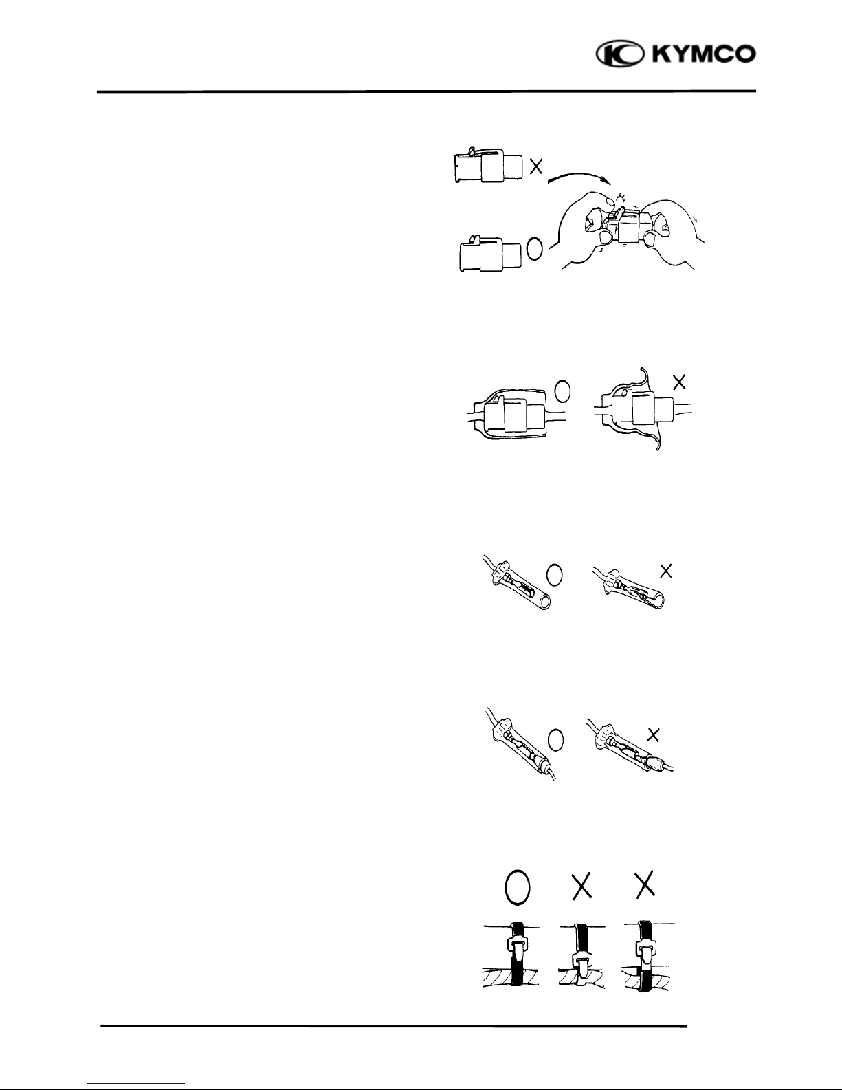
The connector shall be inserted
completely.
If the double connector has a lock,
lock it at the correct position.
Check if there is any loose wire.
Before connecting a terminal, check
for damaged terminal cover or loose
negative terminal.
Check the double connector cover for
proper coverage and installation.
Insert the terminal completely.
Check the terminal cover for proper
coverage.
Do not make the terminal cover opening
face up.
Secure wire harnesses to the frame with
their respective wire bands at the
designated locations.
Tighten the bands so that only the
insulated surfaces contact the wire
harnesses.
Snapping!
Page 9
1. GENERAL INFORMATION
1-7
Mongoose/KXR 250
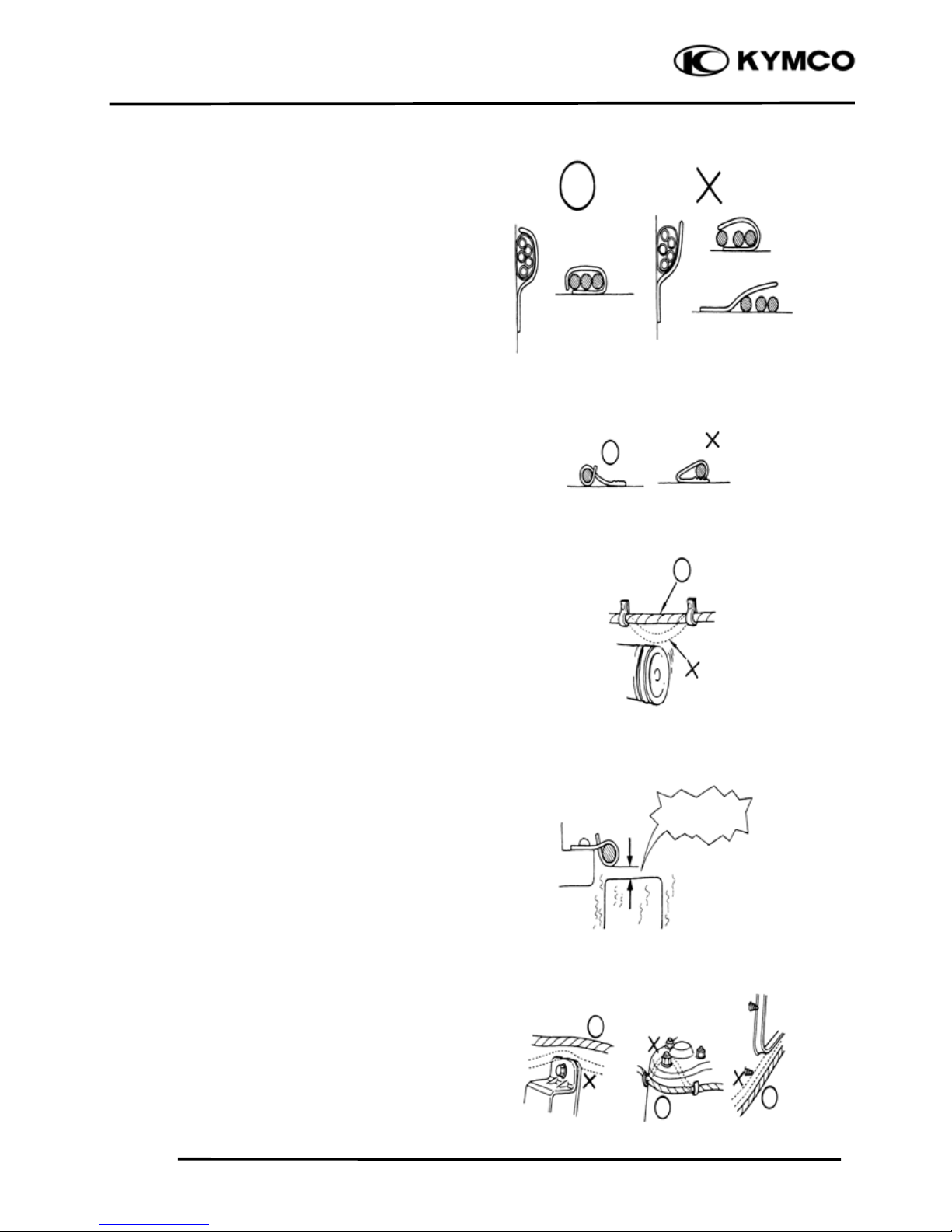
After clamping, check each wire to make
sure it is secure.
Do not squeeze wires against the weld or
its clamp.
After clamping, check each harness to
make sure that it is not interfering with
any moving or sliding parts.
When fixing the wire harnesses, do not
make it contact the parts which will
generate high heat.
Route wire harnesses to avoid sharp
edges or corners. Avoid the projected
ends of bolts and screws.
Route wire harnesses passing through the
side of bolts and screws. Avoid the
projected ends of bolts and screws.
N
o Contact !
Page 10
1. GENERAL INFORMATION
1-8
Mongoose/KXR 250
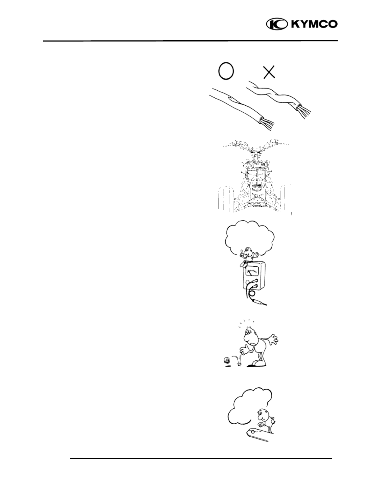
Route harnesses so they are neither
pulled tight nor have excessive slack.
Protect wires and harnesses with
electrical tape or tube if they contact a
sharp edge or corner.
When rubber protecting cover is used to
protect the wire harnesses, it shall be
installed securely.
Do not break the sheath of wire.
If a wire or harness is with a broken
sheath, repair by wrapping it with
protective tape or replace it.
When installing other parts, do not press
or squeeze the wires.
Do not pull
too ti
g
ht!
Do not press
or squeeze
the wire.
Page 11
1. GENERAL INFORMATION
1-9
Mongoose/KXR 250
After routing, check that the wire
harnesses are not twisted or kinked.
Wire harnesses routed along with
handlebar should not be pulled tight, have
excessive slack or interfere with adjacent
or surrounding parts in all steering
positions.
When a testing device is used, make sure
to understand the operating methods
thoroughly and operate according to the
operating instructions.
Be careful not to drop any parts.
When rust is found on a terminal, remove
the rust with sand paper or equivalent
before connecting.
Do you understand
the instrument? Is
the instrument set
correctly?
Remove Rust !
Page 12
1. GENERAL INFORMATION
1-10
Mongoose/KXR 250
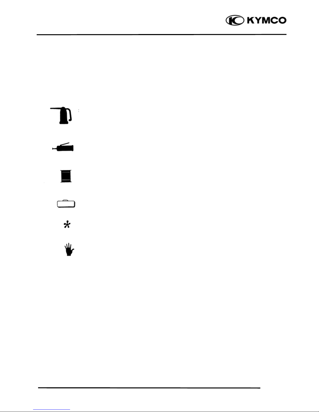
Symbols:
The following symbols represent the
servicing methods and cautions included
in this service manual.
: Apply engine oil to the
specified points. (Use
designated engine oil for
lubrication.)
: Apply grease for
lubrication.
: Transmission Gear Oil
(90#)
: Use special tool.
: Caution
: Warning
Engine Oil
Grease
Gear Oil
Special
Page 13
1. GENERAL INFORMATION
1-11
Mongoose/KXR 250
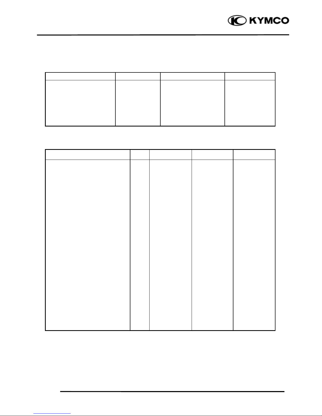
TORQUE VALUES
STANDARD TORQUE VALUES
Ite
m
Torque (kgf-m
)
Ite
m
Torque (kgf-m
)
5mm bolt and nut
6mm bolt and nut
8mm bolt and nut
10mm bolt and nut
12mm bolt and nut
14mm bolt and nut
0.45~0.6
0.8~1.2
1.8~2.5
3.0~4.0
5.0~6.0
6.0~8.0
4mm screw
5mm screw
6mm screw, SH bolt
6mm flange bolt and nut
8mm flange bolt and nut
10mm flange bolt and nut
0.2~0.4
0.35~0.5
0.7~1.1
1.0~1.4
2.4~3.0
3.5~4.5
Torque specifications listed below are for important fasteners.
ENGINE
Item Q‘ty Thread dia.(mm) Torque (kgf-m) Remarks
Stud bolt
Oil filter screen cap
Seat ball stopper bolt
L cover
Cam shaft holder
Tappet ADJ nut
Pivot tensioner bolt
Lifter tensioner bolt
Lifter tensioner cap
Mission case bolt
Mission fill bolt
Driver face nut
Clutch outer nut
Drive plate nut
Oneway clutch bolt
ACG flywheel nut
Spark plug
Water pump impeller
Drain plug
Oil pump screw
Head CYL stud bolt (IN pipe)
Head CYL stud bolt (EX pipe)
A.C.G Startor
4
1
1
10
4
2
1
2
1
9
1
1
1
1
3
1
1
1
1
1
2
2
3
8
30
14
6
8
5
8
6
6
8
12
14
12
28
8
14
12
7
12
3
6
8
5
0.7~1.1
1.0~2.0
4.5~5.0
1.0~1.4
2.3~2.7
0.7~1.1
0.8~1.2
1.0~1.4
0.35~0.5
2.4~3.0
2.0~3.0
9.0~10.0
5.0~6.0
5.0~6.0
1.8~2.2
5.5~6.5
1.5~2.0
1.0~1.4
2.0~3.0
0.1~0.3
0.7~1.1
0.7~1.1
0.8~1.0
Apply oil
Apply oil
Apply oil
Apply thread
lock
Page 14
1. GENERAL INFORMATION
1-12
Mongoose/KXR 250
FRAME
Item Q‘ty Thread dia.(mm) Torque (kgf-m) Remarks
Steering stem nut
Front swing arm nut
Front wheel nut
Rear wheel nut
Front wheel hub nut
Rear wheel hub nut
Front shock absorber upper mount bolt
Front shock absorber lower mount bolt
Rear shock absorber upper mount bolt
Rear shock absorber lower mount bolt
Rear swing arm axle
Rear hub nut
Rear wheel shaft nut
Rear engine bracket upper bolt
Rear engine bracket lower bolt
Engine hanger bracket bolt
Exhaust muffler lock bolt (frame)
Exhaust muffler lock nut (engine)
Rod-end nut
1
8
8
8
2
2
2
2
1
1
1
2
2
1
1
1
2
2
4
14
10
12
12
14
16
10
10
10
10
14
10
40
10
10
10
8
8
8
6.0~8.0
4.0~5.0
4.0~5.0
4.0~5.0
6.0~8.0
9.0~11.0
3.5~4.5
3.5~4.5
3.5~4.5
3.5~4.5
6.0~8.0
3.5~4.5
11.0~13.0
3.5~4.5
3.5~4.5
3.5~4.5
3.2~3.8
1.8~2.2
2.5~3.5
SPECIAL TOOLS
Tool Name Tool No. Remarks Ref. Page
Flywheel puller E003
Valve adjuster E012
Valve spring compressor E040
Oil seal and bearing install E014
Universal holder E017
Flywheel holder E021
Clutch spring compressor E034
Bearing puller E037
Nut wrench F010
Page 15
1. GENERAL INFORMATION
1-13
Mongoose/KXR 250
LUBRICATION POINTS
ENGINE
Lubrication Points Lubricant
Valve guide/valve stem movable part
Cam lobes
Valve rocker arm friction surface
Cam chain
Cylinder lock bolt and nut
Piston surroundings and piston ring grooves
Piston pin surroundings
Cylinder inside wall
Connecting rod/piston pin hole
Connecting rod big end
Crankshaft right side oil seal
Crankshaft one-way clutch movable part
Oil pump drive chain
Balance gear
A.C. generator
Starter one-way clutch
Bearing movable part
O-ring face
Oil seal lip
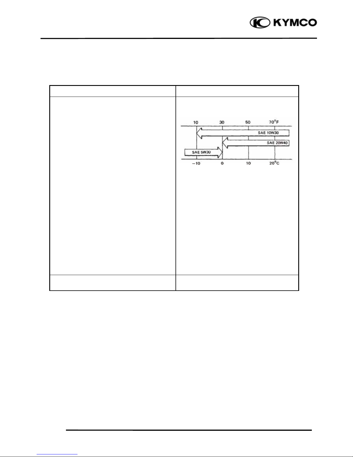
•Genuine KYMCO Engine Oil (SAE15W -40)
•API SG Engine Oil
Transmission gear and movable parts Gear oil: SAE90#
Page 16
1. GENERAL INFORMATION
1-14
Mongoose/KXR 250
FRAME
The following is the lubrication points for the frame.
Use general purpose grease for parts not listed.
Apply clean engine oil or grease to cables and movable parts not specified. This will avoid
abnormal noise and rise the durability of the ATV.
Steering Column Uppe
r
Throttle Cable
Steering Column Lowe
r
Front Swing Arm Bush
Front Swing Ar
m
Page 17
1. GENERAL INFORMATION
1-15
Mongoose/KXR 250
Sprocket hub/Rea
r
Axle Hub Collar/Oil
Seal/Bearing
Driven Sprocket
Rear Swing Ar
m
Axle
Page 18
1. GENERAL INFORMATION
1-16
Mongoose/KXR 250
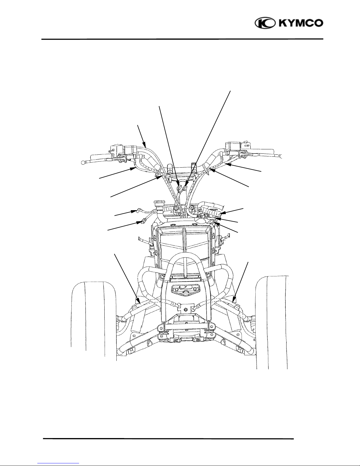
CABLE & HARNESS ROUTING
Headlight Wire
Pilot Lamp Wire
Handlebar Switch Wire
Ignition Switch Wire
Rear Brake Fluid Hose
Harness Wire
Motor Fan Cor
d
Thermostatic Switch Wire
Left Front Brake Fluid Hose
Right Front Brake Fluid Hose
Thermostatic Sensor Wire
Front Brake Fluid Hose
Stop Switch Cor
d
Throttle Cable
Page 19
1. GENERAL INFORMATION
1-17
Mongoose/KXR 250
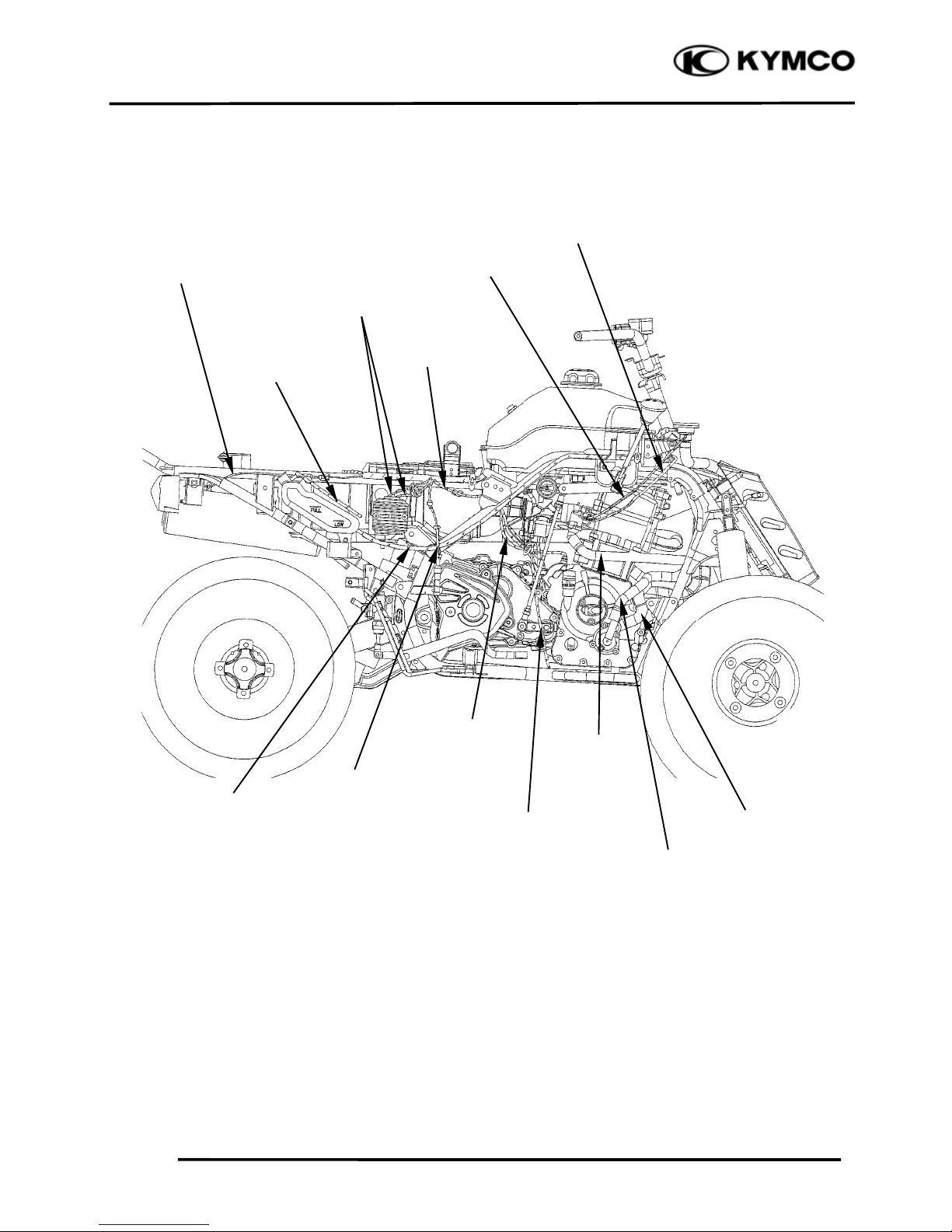
Air Vent Tube
Coolant Reservoi
r
Breather Hose
Outlet Water Hose
Temperature Sensor Wire
Inlet Water Hose
Water Hose
Carburetor Drain Tube
Start Motor Cable
Radiator Overflow Tube
A.C.G Cor
d
REG.REC Cor
d
Tail Light Cor
d
Stop Switch Cor
d
Page 20
1. GENERAL INFORMATION
1-18
Mongoose/KXR 250
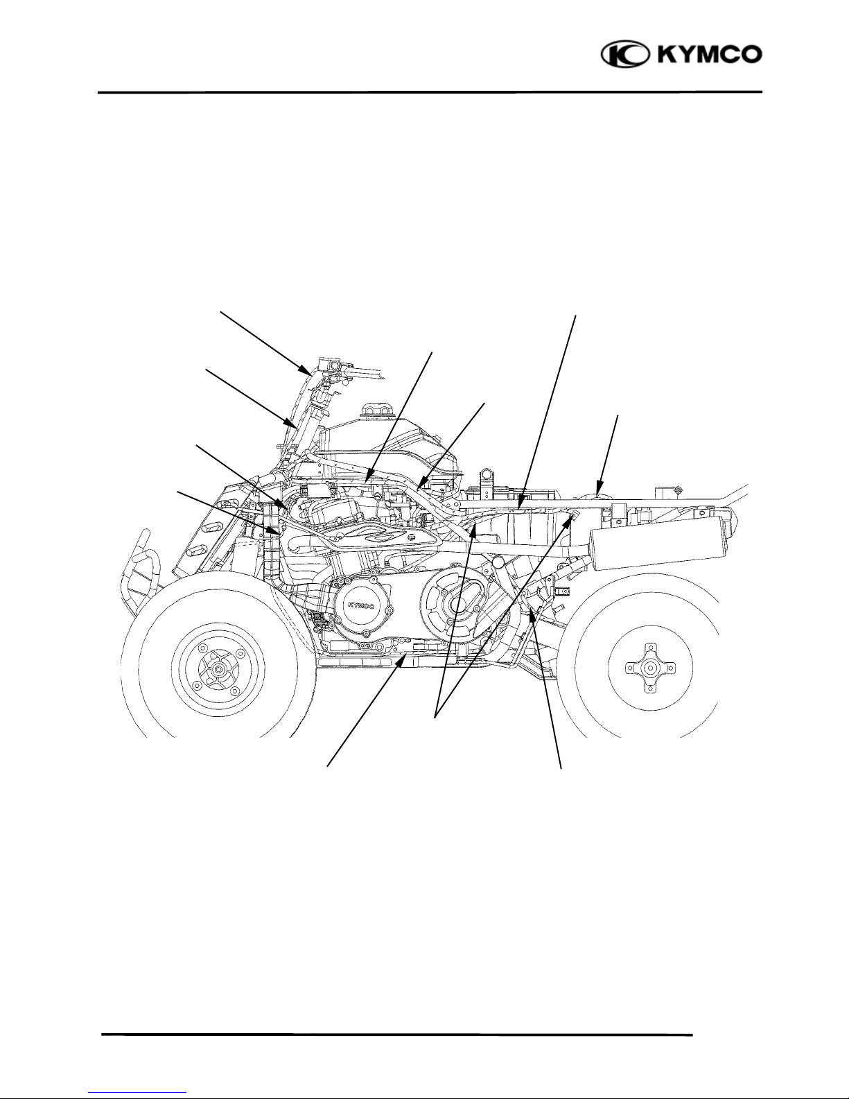
Motor Fan Cor
d
Handlebar Switch Cor
d
Rear Brake Fluid Hose
Harness Wire
Blow By Hose
Rear Brake Fluid Hose
Start Motor Cable
Battery Cable
Crankcase Breather Hose
Rear Brake Fluid Hose
Page 21
1. GENERAL INFORMATION
1-19
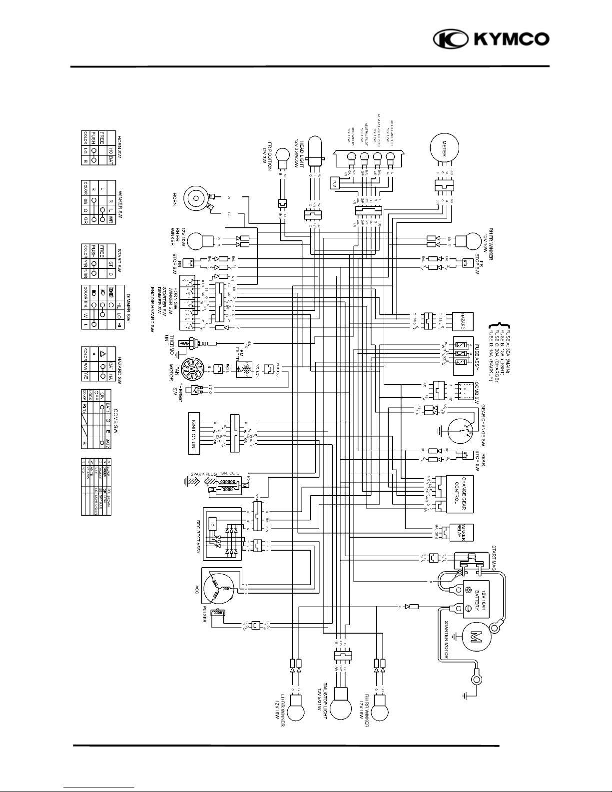
Mongoose/KXR 250
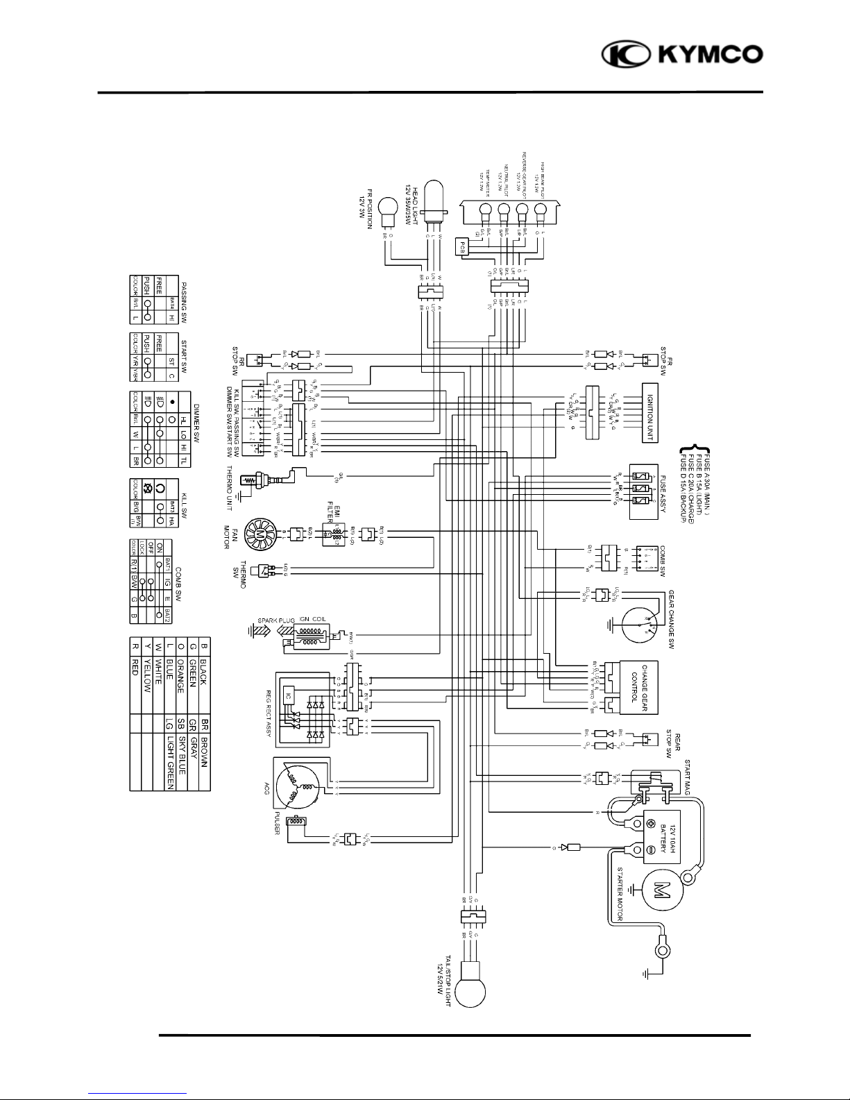
WIRING DIAGRAM (OFF ROAD)
Page 22
1. GENERAL INFORMATION
1-20
Mongoose/KXR 250
WIRING DIAGRAM (ON ROAD)
Page 23
1. GENERAL INFORMATION
1-21
Mongoose/KXR 250
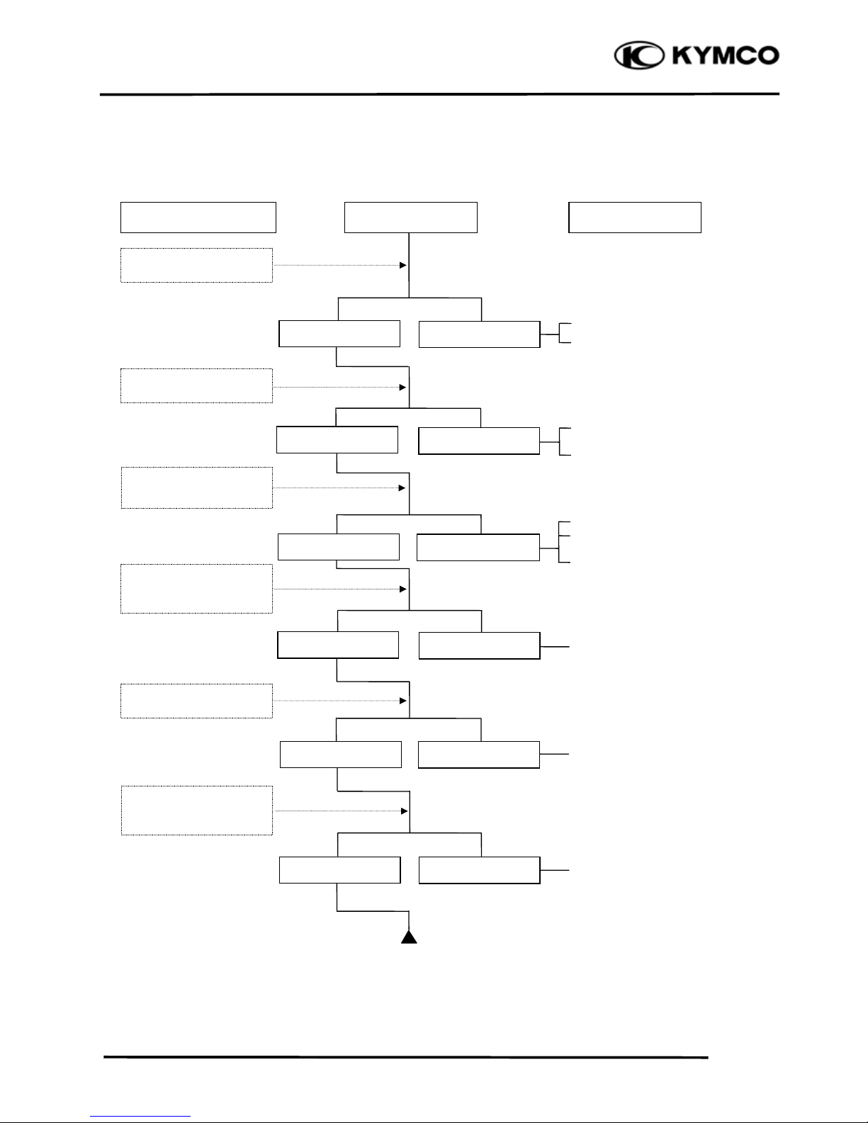
TROUBLESHOOTING
ENGINE WILL NOT START OR IS HARD TO START
Empty fuel tank
Clogged fuel line between fuel
tank and carburetor
Clogged float oil passage
Clogged fuel tank cap breather
hole
Clogged fuel filter
Clogged fuel valve passage
Faulty spark plug
Fouled spark plug
Faulty ignition unit
Faulty change gear control unit
Faulty pulser coil
Broken or shorted ignition coil
Broken or shorted exciter coil
Faulty ignition switch
Weak or dead battery
Faulty starter clutch
Valve clearance too small
Valve stuck open
Worn cylinder, piston and piston
rings
Leaking cylinder head gasket
Air leaking through intake pipe
Leaking intake manifold
Incorrect ignition timing
Incorrectly adjusted air screw
Flooded carburetor
Clogged air cleaner
Throttle valve excessively open
Check if fuel reaches
carburetor by loosening
drain screw
Remove spark plug and
install it into spark plug
cap to test spark by
connecting it to engine
ground
Inspection/Adjustment
Probable Cause
Spark jumps
Normal
compression
Engine does no
t
fire
Weak or no spark
Low or no
compression
Engine fires bu
t
does not start
Test cylinde
r
compression
Start engine by following normal starting
p
rocedure
Remove spark plug and
inspect again
Symptom
Fuel reaches
carburetor
Fuel does no
t
reach carburetor
Wet spark plug
Dry spark plug
Page 24
1. GENERAL INFORMATION
1-22
Mongoose/KXR 250
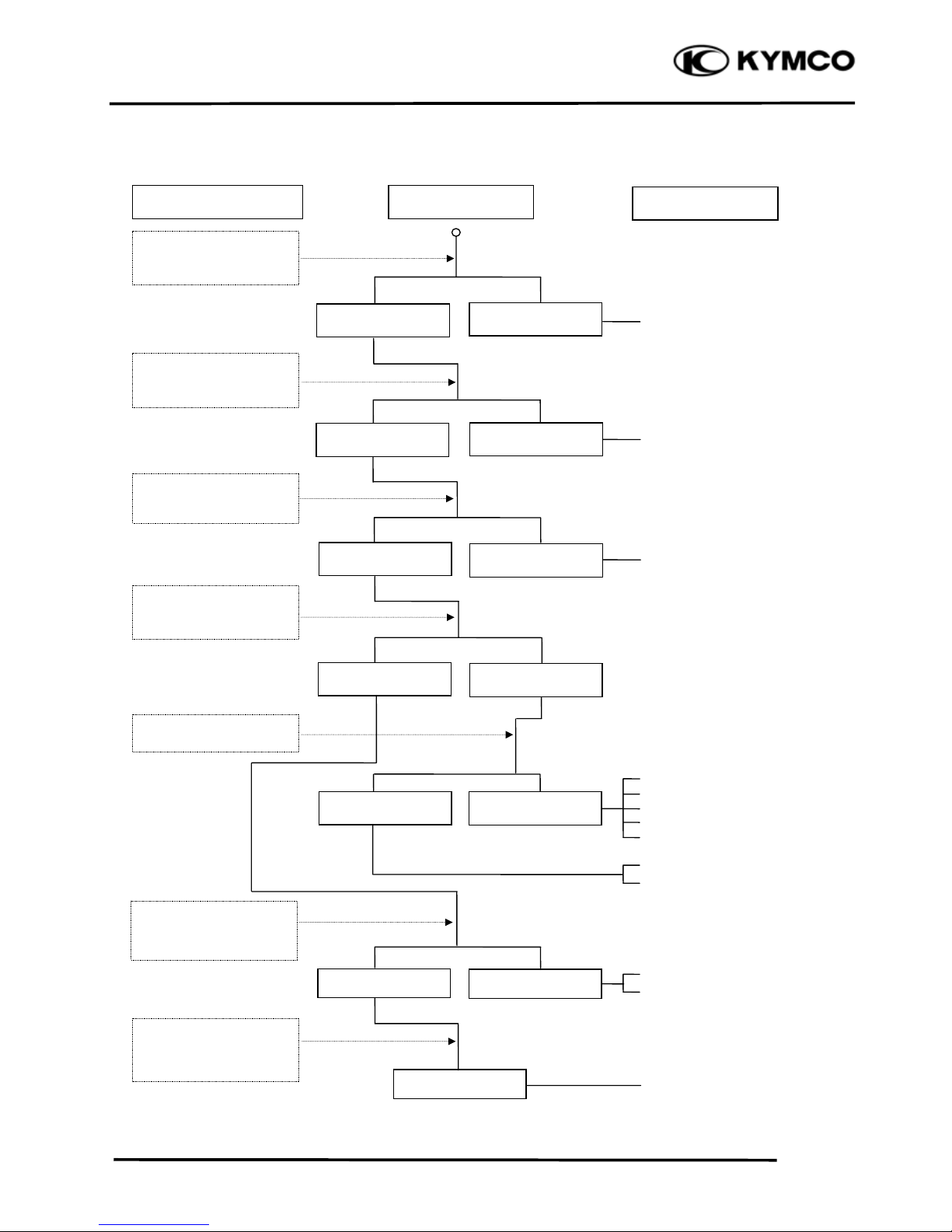
ENGINE LACKS POWER
Clogged air cleaner
Restricted fuel flow
Clogged fuel tank cap breather hole
Clogged exhaust muffler
Carburetor fuel level too low
Faulty ignition unit
Faulty pulser coil
Improper valve clearance
adjustment
Excessively worn valve seat
(protruded valve stem)
Improper valve and seat contact
Worn cylinder and piston rings
Leaking cylinder head gasket
Improper valve timing
Clean and unclog
Fouled spark plug
Incorrect heat range plug
Oil level too high
Oil level too low
Oil not changed
Clogged oil line
Faulty oil pump
Coolant level too low
Worn cylinder and piston rings
Mixture too lean
Poor quality fuel
Excessive carbon build-up in
combustion chamber
Ignition timing too early
Excessive carbon build-up in
combustion chamber
Poor quality fuel
Clutch slipping
Mixture too lean
Ignition timing too early
Start engine and
accelerate lightly for
Inspection/Adjustment
Symptom
Probable Cause
Engine speed
Correct timin
g
Engine speed does no
t
increase sufficientl
y
Incorrect timin
g
Check ignition timing
(using a timing light)
Test cylinder compression
Check carburetor fo
r
clogging
Rapidly accelerate or run
at hi
g
h speed
Remove spark plug and
inspec
t
Check if engine overheats
Check valve clearance
Correc
t
Incorrec
t
N
ormal
com
p
ression
Abnormal
compression
Remove oil dipstick and
check oil level and condition
Remove cylinder head oil
pip
e bolt and inspec
t
Engine overheats
Engine does no
t
overheats
Plug not fouled o
r
discolored
Plug fouled o
r
discolored
Correct and no
t
contaminated
Incorrect o
r
contaminated
Valve train lubricated
prop
erl
y
Valve train no
t
lubricated properl
y
Engine does not knock
Engine knocks
Not clogged
Clogged
Page 25
1. GENERAL INFORMATION
1-23
Mongoose/KXR 250
POOR PERFORMANCE (ESPECIALLY AT IDLE AND LOW SPEEDS)
Faulty ignition unit
Faulty pulser coil
Mixture too rich (turn screw
out)
Mixture too lean (turn screw in)
Deteriorated O-ring
Carburetor not securely
tightened
Damaged insulator rubber
Faulty or fouled spark plug
Faulty ignition unit
Faulty A.C. generator
Faulty ignition coil
Broken or shorted spark plug
wire
Faulty ignition switch
Remove spark plug and
install it into spark plug
cap to test spark by
connecting it to engine
g
round
Inspection/Adjustment Symptom Probable Cause
Check ignition timing
Check carburetor gaske
t
for air leaks
Check carburetor ai
r
screw adjustment
Correct timing
Incorrect timing
Correctly adjusted
No air leak
Air leaks
Good spark
Weak or inter-
mittent spark
Incorrectly adjusted
Page 26
1. GENERAL INFORMATION
1-24
Mongoose/KXR 250
POOR PERFORMANCE (AT HIGH SPEED)
Faulty ignition unit
Faulty pulser coil
Improperly adjusted valve
clearance
Worn valve seat
Empty fuel tank
Clogged fuel tube or filter
Clogged Fuel tank cap breather
hole
Clean and unclog
Cam timing gear aligning marks
not aligned
Faulty spring
Inspection/Adjustment Symptom Probable Cause
Check ignition timing
Check carburetor jets
for clogging
Check fuel pump fo
r
fuel supply
Correct timing
Incorrect timing
Check valve spring
tension
Check valve clearance
Fuel flows freely
Fuel flow restricted
Correc
t
Incorrec
t
Not clogged
Clogged
Correctly adjusted
Incorrectly adjusted
Not weakened
Weak spring
Check valve timing
Page 27
1. GENERAL INFORMATION
1-25
Mongoose/KXR 250
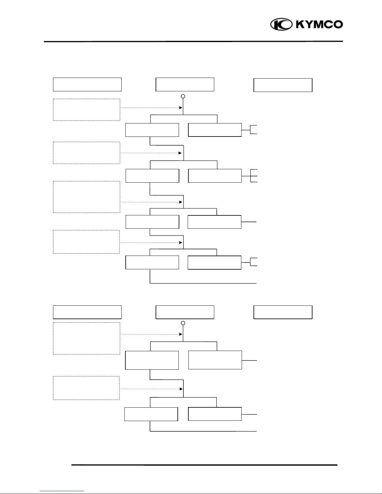
POOR CHARGING (BATTERY OVER DISCHARGING OR OVERCHARGING)
Undercharging
Dead battery
Faulty battery
Faulty A.C. generator coil
Broken yellow wire
Shorted pink and yellow
wires
Broken red wire
Faulty regulator/rectifier
Poorly connected coupler
Faulty A.C. generator
Overcharging
Broken green wire
Poorly connected coupler
Faulty regulator/rectifier
Start engine and tes
t
limit voltage of battery
terminals
Connect battery (+) wire
to regulator/rectifier
coupler red wire and
battery (-) wire to engine
g
round and test voltage
Inspection/Adjustment
Inspection/Adjustment
Symptom
Symptom
Probable Cause
Probable Cause
Normal voltage
B
attery has voltage
with ignition
switch “ON”
Normal
Voltage does no
t
B
attery has no
voltage with ignition
switc
h
“ON”
Resistance too high
Normal voltage No voltage
Measure resistance
between AC generator
coil terminals
Normal
Abnormal
Check regulator/rectifier
coupler for loose
connection
Normal
Abnormal
Connect battery (+) wire
to regulator/rectifier
coupler green wire and
battery (-) wire to engine
g
round and test voltage
Check regulator/rectifier
coupler for loose
connection
Page 28
1. GENERAL INFORMATION
1-26
Mongoose/KXR 250
NO SPARK AT SPARK PLUG
Faulty spark plug
Loose spark plug cap
Poorly connected coupler
Faulty ignition switch
Weak battery
Faulty pulser coil
Faulty ignition coil
Faulty charging system
Broken wire harness
Poorly connected coupler
Faulty ignition unit
Faulty change gear control
unit
Faulty ignition coil
Replace with a new
spark plug and inspect
a
g
ain
Check ignition unit
coupler for looseness
Inspection/Adjustment Symptom
Probable Cause
Normal
Abnormal
Normal
Abnormal
Normal
Abnormal
Abnormal
Measure resistance
between terminals of
i
g
nition unit couple
r
Check related parts
Check ignition coil with
a ignition unit tester
Weak or no spark
Not loose
Good spark
Loose
Good
Good
Check spark plug cap
and high-tension wire
for looseness
Check ignition unit
with a ignition unit
teste
r
Page 29

2. FRAME COVERS/EXHAUST MUFFLER
2-0
Mongoose/KXR 250
2
__________________________________________________________________________________
__________________________________________________________________________________
__________________________________________________________________________________
__________________________________________________________________________________
__________________________________________________________________________________
FRAME COVERS/EXHAUST MUFFLER
__________________________________________________________________________________
SERVICE INFORMATION------------------------------------------------ 2- 2
TROUBLESHOOTING----------------------------------------------------- 2- 2
FRAME COVERS----------------------------------------------------------- 2- 3
EXHAUST MUFFLER REMOVAL-------------------------------------- 2- 7
2
Page 30
2. FRAME COVERS/EXHAUST MUFFLER
2-1
Mongoose/KXR 250
Page 31

2. FRAME COVERS/EXHAUST MUFFLER
2-2
Mongoose/KXR 250
SERVICE INFORMATION
GENERAL INSTRUCTIONS
• When removing frame covers, use special care not to pull them by force because the cover joint
claws may be damaged.
• Make sure to route cables and harnesses according to the Cable & Harness Routing.
TORQUE VALUES
Exhaust muffler lock bolt 3.2~3.8kgf-m
Exhaust muffler lock nut 1.8~2.2kgf-m
TROUBLESHOOTING
Noisy exhaust muffler
• Damaged exhaust muffler
• Exhaust muffler joint air leaks
Lack of power
• Caved exhaust muffler
• Exhaust muffler air leaks
• Clogged exhaust muffler
Page 32

2. FRAME COVERS/EXHAUST MUFFLER
2-3
Mongoose/KXR 250
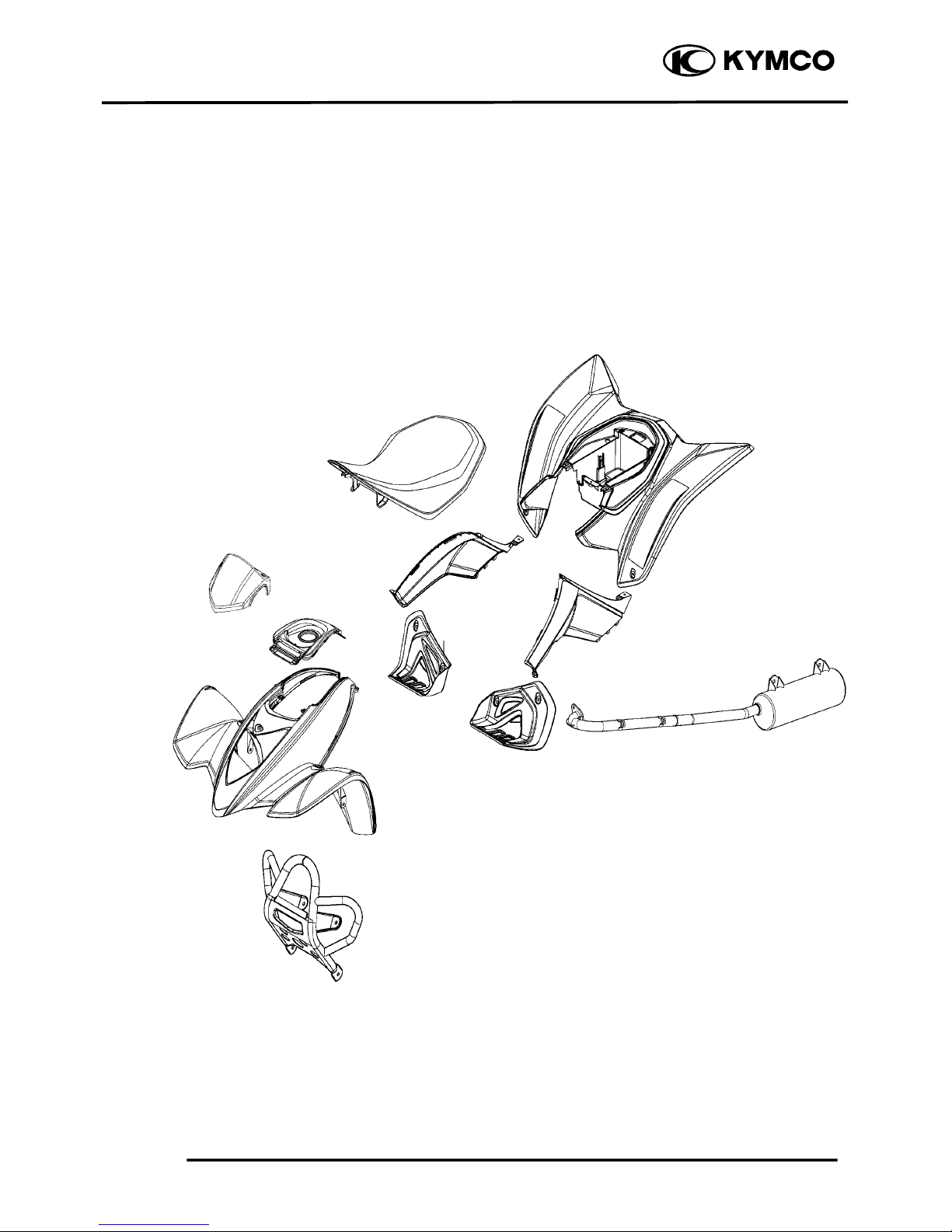
FRAME COVERS
SEAT REMOVAL
Pull the lever right and pull up the seat at
the rear.
Remove the seat.
LEFT/RIGHT FRAME COVER
REMOVAL
Remove the seat. (See page 2-3)
Remove the screw and two bolts at the left
frame cover, then remove left frame cover.
Remove the screw and two bolts at the right
frame cover, then remove right frame cover.
REAR FENDER REMOVAL
Remove seat. (See page 2-3)
Remove right and left frame cover. (See
page 2-3)
Remove battery. (See page 16-4)
Remove the fuse box.
Remove the screw attaching the ignition
unit/change gear control unit/starter relay
holder and remove holder.
Sea
t
Frame LeftCove
r
Bolts
Screw
Battery
Bolts
During removal, do not pull the joint
claws forcedly to avoid damage.
*
Leve
r
Screw
Frame RightCove
r
Screw and Holde
r
Fuse Box
Page 33

2. FRAME COVERS/EXHAUST MUFFLER
2-4
Mongoose/KXR 250
Remove the three bolts at the rear fender.
Remove the two screws attaching the right
and left floor board.
Remove the two screws attaching the frame
body and three screws attaching the outlet
hose, then remove the rear fender.
HANDLEBAR COVER REMOVAL
Remove the two screws at the handlebar
cover.
Disconnect the indicator lamp coupler, then
remove the handlebar cover.
Bolts
Screws
Screws
Screws
Screws
During removal, do not pull the joint
claws forcedly to avoid damage.
*
Outlet Hose
Indicator Lamp couple
r
Page 34

2. FRAME COVERS/EXHAUST MUFFLER
2-5
Mongoose/KXR 250
CENTER FRAME COVER REMOVAL
Remove the seat. (See page 2-3)
Remove the fuel fill cap.
Remove the four bolts at the center frame
cover, then remove the center frame cover.
FRONT FENDER REMOVAL
Remove the seat (See page 2-3), right and
left side frame cover (See page 2-3) and
center frame cover. (See page 2-5)
Remove the two bolts at the front fender left
side.
Remove the two screws attaching the inlet
hose.
Remove the two bolts at the front fender
right side.
Remove the screw, then remove the drive
select grip from the drive select lever.
Bolts
Bolts
Select Grip
Bolts
Screw
Screws
After remove, be sure to tighten the fuel
fill cap.
*
Fuel Fill Cap
Page 35

2. FRAME COVERS/EXHAUST MUFFLER
2-6
Mongoose/KXR 250
Disconnect headlight and ignition switch
couplers, then remove the front fender.
RIGHT AND LEFT FLOOR BOARD
REMOVAL
Remove the four screws at the floor board,
then remove the floor board.
FRONT CARRIER REMOVAL
Remove the four bolts at the front carrier,
then remove the front carrier.
Ignition Couple
r
Headlight Couple
r
Screws
Bolts
Page 36

2. FRAME COVERS/EXHAUST MUFFLER
2-7
Mongoose/KXR 250
EXHAUST MUFFLER
REMOVAL
Remove the two exhaust pipe joint lock
nuts.
Remove the bolt at the exhaust muffler,
disconnect the exhaust pipe from the
exhaust muffler.
Inspect the gasket.
If the exhaust gas leaks, the gasket should
be replaced.
Install by reversing the removal sequence.
Torque:
Exhaust muffler lock bolt: 3.2~3.8kgf-m
Exhaust muffler lock nut: 1.8~2.2kgf-m
Remove the nut and bolt at the exhaust
muffler, then remove the exhaust muffler.
INSTALLATION
Install by reversing the removal sequence.
Torque:
Exhaust muffler lock bolt and nut:
3.2~3.8kgf-m
N
uts
Bol
t
Gaske
t
Nut
Bol
t
Be sure to install a new exhaust gasket.
*
Page 37

3. INSPECTION/ADJUSTMENT
3-0
Mongoose/KXR 250
3
__________________________________________________________________________________
__________________________________________________________________________________
__________________________________________________________________________________
__________________________________________________________________________________
__________________________________________________________________________________
INSPECTION/ADJUSTMENT
__________________________________________________________________________________
SERVICE INFORMATION------------------------------------------------ 3- 1
MAINTENANCE SCHEDULE-------------------------------------------- 3- 2
FUEL LINE/THROTTLE OPERATION/AIR CLEANER ------------ 3- 3
AIR FILTER FOR DRIVE BELT/ SPARK PLUG --------------------- 3- 6
VALVE CLEARANCE/CARBURETOR IDLE SPEED--------------- 3- 7
IGNITION TIMING/CYLINDER COMPRESSION ------------------- 3- 8
ENGINE OIL----------------------------------------------------------------- 3- 9
TRANSMISSION OIL REPLACEMENT ------------------------------- 3-10
DRIVE BELT/BRAKE PADS/BRAKE FLUID INSPECTION ------ 3-11
HEADLIGHT AIM/ STEERING SYSTEM INSPECTION ----------- 3-12
TOE-IN ADJUSTMENT --------------------------------------------------- 3-13
WHEELS/TIRES ------------------------------------------------------------ 3-14
DRIVE CHAIN SLACK ADJUSTMENT-------------------------------- 3-16
DRIVE SELECT LEVER ADJUSTMENT ------------------------------ 3-18
CABLE INSPECTION AND LUBRICATION-------------------------- 3-19
REAR SUSPENSION LUBRICATION---------------------------------- 3-19
COOLING SYSTEM-------------------------------------------------------- 3-20
3
Page 38

3. INSPECTION/ADJUSTMENT
3-1
Mongoose/KXR 250
SERVICE INFORMATION
GENERAL
! WARNING
•Before running the engine, make sure that the working area is well-ventilated. Never run the
engine in a closed area. The exhaust contains poisonous carbon monoxide gas which may
cause death to people.
•Gasoline is extremely flammable and is explosive under some conditions. The working area
must be well-ventilated and do not smoke or allow flames or sparks near the working area or
fuel storage area.
SPECIFICATIONS
ENGINE
Throttle grip free play : 1~4mm
Spark plug gap : 0.6~0.7mm
Spark plug: Standard : DPR7EA-9
Valve clearance : IN: 0.1mm
EX: 0.1mm
Idle speed : 1500±100rpm
Engine oil capacity:
At disassembly : 1.6 liter
At change : 1.4 liter
Gear oil capacity :
At disassembly : 400cc
At change : 300cc
Cylinder compression : 15±2kg/cm²
Ignition timing : BTDC 5°±1°/2000rpm
TIRE PRESSURE
1 Rider
Front 0.28kgf/cm²
Rear 0.28kgf/cm²
TIRE SIZE:
Front : 21*7-10
Rear : 20*11-9
TORQUE VALUES
Front wheel nut 4.0~5.0kgf-m
Rear wheel nut 4.0~5.0kgf-m
Page 39

3. INSPECTION/ADJUSTMENT
3-2
Mongoose/KXR 250
MAINTENANCE SCHEDULE
This chapter includes all information necessary to perform recommended inspections and
adjustments. These preventive maintenance procedures, if followed, will ensure more reliable
vehicle operation and a longer service life. The need for costly overhaul work will be greatly
reduced. This information applies to vehicles already in service ad well as new vehicles that are
being prepared for sale. All service technicians should be familiar with this entire chapter.
Initial Every
Item Remarks
1
month3month6month6month
1
year
Valves
Check valve clearance. Adjust if
necessary.
○○○○
Spark plug
Check condition. Adjust gap and
clean. Replace if necessary.
○○○○○
Air filter element (for
engine and drive belt
compartment)
Clean.
Replace if necessary.
Every 20~40 hours
(
more often in wet or dusty areas.
)
Carburetor
Check idle speed/starter operation.
Adjust if necessary.
○○○○
Fuel line
Check fuel hose for cracks or
damage. Replace if necessary.
○○○
Engine oil
Replace (Warm engine before
draining).
○○○○
Coolant
Check coolant leakage.
Replace if necessary.
Replace coolant every 24 months.
○○○○○
Oil strainer
Clean.
Replace if necessary.
○○○
Drive chain
Check and adjust
slack/alignment/clean/lube.
○○○○○
Transmission oil
Check oil leakage. Replace every
12 months.
○○
Brake system
Check operation and brake fluid.
Replace brake pad if necessary.
○○○○○
Drive belt
Check operation/replace if damage
or excessive wear.
○○
Wheels
Check balance/damage/runout.
Replace if necessary.
○○○○
Wheel bearings
Check bearing assembly for
looseness/damage. Replace if
damaged.
○○○○
Steering system
Check operation/replace if damage.
Check toe-in/adjust if necessary.
○○○○○
Rear swing arm shafts Lubricate every 6 months. ○○○
Fitting/Fasteners
Check all chassis fittings and
fasteners. Correct if necessary.
○○○○○
•In the interest of safety, we recommend these items should be serviced only by an authorized
KYMCO motorcycle dealer.
Page 40

3. INSPECTION/ADJUSTMENT
3-3
Mongoose/KXR 250
FUEL LINE
Check the fuel tubes and replace any parts,
which show signs of deterioration, damage
or leakage.
THROTTLE OPERATION
Check the throttle to swing for smooth
movement.
Measure the throttle to swing free play.
Free Play (A): 1~4mm
To adjust throttle free play:
Slide the rubber sleeve back to expose the
throttle cable adjuster.
Loosen the lock nut, then turn the adjuster
to obtain the correct free play. (1~4 mm or
0.04~0.16 in)
Tighten the lock nut and reinstall the sleeve.
AIR CLEANER
AIR CLEANER REPLACEMENT
Remove the seat. (See page 2-3)
Unlatch the four retainer clips and remove
the air cleaner housing cover.
Do not smoke or allow flames or sparks
in your working area.
*
Fuel Filte
r
Fuel tubes
Lock nu
t
Retainer Clips
Air Cleaner Housing Cove
r
Cable adjuste
r
Rubber sleeve
Page 41

3. INSPECTION/ADJUSTMENT
3-4
Mongoose/KXR 250
Unscrew the clamp and remove the air
cleaner assembly from the air cleaner
housing.
Remove the screw and remove the air
cleaner assembly from the air cleaner
holder.
Remove the air cleaner and air cleaner
screen from the air cleaner body.
Remove the air cleaner net from the air
cleaner.
Reassemble by reversing the disassembly
sequence.
Air Cleaner AssemblyScrew
Screw Air Cleaner Holde
r
Air Cleane
r
Air Cleaner screen
Air Cleaner body
Page 42

3. INSPECTION/ADJUSTMENT
3-5
Mongoose/KXR 250
CLEAN AIR FILTER ELEMENT
Wash the element gently, but throughly in
solvent.
Squeeze the excess solvent out of the
element and let dry.
Apply the engine oil.
Squeeze out the excess oil.
More frequent replacement is required when
riding in unusually dusty or rainy areas.
AIR CLEANER HOUSING DRAIN
Remove the drain tube by removing the
clip.
Drain the deposits.
Reinstall the drain tube, securing it with the
clip.
Use parts cleaning solvent only. Neve
r
use gasoline or low flash point solvents
which may lead to a fire or explosion.
*
Do not twist or wring out the foa
m
element. This could damage the foam
material.
*
The element should be wet but not
dripping.
*
Air Cleaner Housing
Drain Tube
Clip
Page 43

3. INSPECTION/ADJUSTMENT
3-6
Mongoose/KXR 250
Gap, Wear, and Fouling Deposits
AIR FILTER FOR DRIVE BELT
To clean the air filter:
Remove the two screws attaching front
fender and remove air filter housing.
Remove the two screws and remove air
filter housing cover.
Remove the air filter from the housing.
Tap the air filter lightly to remove most of
the dust and dirt.
Blow out the remaining dirt with
compressed air.
If the element is damaged, replace it.
Reassemble by reversing the disassembly
sequence.
SPARK PLUG
Remove ignition coil cap and spark plug.
Check the spark plug for wear and fouling
deposits.
Clean any fouling deposits with a spark
plug cleaner or a wire brush.
Specified Spark Plug: DPR7EA-9
Measure the spark plug gap.
Spark Plug Gap: 0.6~0.7mm
Cracks, Damage
Washer Deformation
Screws
Air Filter Housing
Screw
Air Filter Cove
r
Air Filte
r
When installing, first screw in the spar
k
plug by hand and then tighten it with a
spark plug wrench.
*
Ignition Coil Cap
Spark Plug
Page 44

3. INSPECTION/ADJUSTMENT
3-7
Mongoose/KXR 250
VALVE CLEARANCE
Remove the cylinder head cover. (See page
7-4)
Turn the flywheel clockwise so that the “T”
mark on the flywheel aligns with the index
mark on the right crankcase cover to bring
the round hole on the camshaft gear facing
up to the top dead center on the
compression stroke.
Inspect and adjust the valve clearance.
Valve Clearance: IN: 0.1mm
EX: 0.1mm
Loosen the lock nut and adjust by turning
the adjusting nut
Tappet adjuster E012
CARBURETOR IDLE SPEED
Warm up the engine before this operation.
Start the engine and connect a tachometer.
Turn the throttle stop screw to obtain the
specified idle speed.
Idle Speed: 1500±100rpm
When the engine misses or run erratic,
adjust the air screw.
Inspect and adjust valve clearance while
the engine is cold (below 35℃).
*
• The engine must be warm for accurate
idle speed inspection and adjustment.
*
Cylinder Head Cove
r
Round Hole
Valve Wrench
Throttle Stop Screw
AirScrew
“T” Mark
• Check the valve clearance again afte
r
the lock nut is tightened.
*
Special
Index Mark
Page 45

3. INSPECTION/ADJUSTMENT
3-8
Mongoose/KXR 250
IGNITION TIMING
Remove the timing hole cap.
Check the ignition timing with a timing
light.
When the engine is running at idle speed,
the ignition timing is correct if the “F” mark
on the flywheel aligns with the index mark
on the right crankcase cover.
CYLINDER COMPRESSION
Warm up the engine before compression
test.
Remove the spark plug.
Insert a compression gauge.
Open the throttle valve fully and push the
starter button to test the compression.
Compression: 15±2kg/cm
2
If the compression is low, check for the
following:
- Leaky valves
- Valve clearance too small
- Leaking cylinder head gasket
- Worn piston rings
- Worn piston/cylinder
If the compression is high, it indicates that
carbon deposits have accumulated on the
combustion chamber and the piston head.
The ignition unit is not adjustable. If the
ignition timing is incorrect, check the
ignition system.
*
Compression Gauge
Timing Hole
Timing Hole Cap
Index Mark
Page 46

3. INSPECTION/ADJUSTMENT
3-9
Mongoose/KXR 250
ENGINE OIL
OIL LEVEL
Place the machine on a level place.
Warm up the engine for several minutes and
stop it.
Check the oil level through the inspection
window.
The oil level should be between the
maximum (H) and minimum (L) marks. If
the level is low, add oil to raise it to the
proper level.
ENGINE OIL REPLACEMENT
Place the machine on a level place.
Warm up the engine for several minutes and
stop it.
Place a container under the engine.
Remove the oil fill cap and drain plug to
drain the oil.
Reinstall the drain plug and tighten the
drain plug to specification.
Torque: 2.0~3.0kgf-m
Fill the engine with oil and install the oil fill
cap.
Oil Capacity: At disassembly: 1.6L
At change: 1.4L
Inspection Window
Lower Level
Upper Level
Run the engine for 2~3 minutes and
check the oil level after the engine is
stopped for 2~3 minutes.
*
Oil Fill Cap
Drain Plu
g
The engine oil will drain more easily
while the engine is warm.
*
Page 47

3. INSPECTION/ADJUSTMENT
3-10
Mongoose/KXR 250
ENGINE OIL REPLACEMENT AND
OIL FILTER CLEANING
Place the machine on a level place.
Warm up the engine for several minutes and
stop it.
Place a container under the engine.
Remove the oil fill cap and oil filter cap to
drain the oil.
Clean the oil strainer with solvent.
Inspect the O-ring and replace if damaged.
Reinstall the O-ring, oil strainer,
compression spring and oil filter cap.
Tighten the oil filter cap to specification.
Torque: 1.0~2.0kgf-m
Fill the engine with oil and install the oil fill
cap.
Oil Capacity: At disassembly: 1.6L
At change: 1.4L
TRANSMISSION OIL
REPLACEMENT
Place the machine on a level place.
Place a container under the engine.
Remove the oil filler bolt and drain plug to
drain the oil.
Reinstall the drain plug and tighten to
specification.
Torque: 2.0~3.0kgf-m
Fill the engine with oil and install the oil
filler bolt.
Oil Capacity: At disassembly: 400cc
At change: 300cc
Start the engine and warm up for a few
minutes. While warming up, check for oil
leakage. If oil leakage is found, stop the
engine immediately and check for the cause.
Oil Filter Ca
p
O-ring
Com
p
ression Sprin
g
Oil Straine
r
Oil Filter Ca
p
Oil Filler Bol
t
Drain Plug
Make sure that the sealing washer is in
good condition.
*
Page 48

3. INSPECTION/ADJUSTMENT
3-11
Mongoose/KXR 250
DRIVE BELT
Remove the left crankcase cover.
Inspect the drive belt for cracks, scaling,
chipping or excessive wear.
Measure the V-belt width
Service limit: 22mm
Replace the drive belt if out of specification.
BRAKE PADS INSPECTION
A wear indicator is provided on each brake.
The indicators allows checking of brake
pads wear. Check the position of the
indicator. If the indicator reaches the wear
limit line, to replace the pads.
BRAKE FLUID INSPECTION
Check if the fluid level is below the lower
level mark through the inspection window.
Drive Bel
t
Front Calipe
r
Rear Calipe
r
Inspection Window (R/L Brake Lever)
Page 49

3. INSPECTION/ADJUSTMENT
3-12
Mongoose/KXR 250
HEADLIGHT AIM
Turn the ignition switch ON and start the
engine.
Turn on the headlight switch.
Adjust the headlight aim by turning the
headlight aim adjusting screw.
STEERING SYSTEM
INSPECTION
Place the machine on a level place.
Check the steering column bushings and
bearings:
Move the handlebar up and down, and/or
back and forth.
Replace the steering column bushings and
or bearings if excessive play
Check the tie-rod ends
Turn the handlebar to the left and/or right
until it stops completely, then slightly move
the handlebar from left to right.
Replace the tie-rod ends if tie-rod end has
any vertical play.
Inspection Window (Rear Brake Pedal)
Adjust Screw
Tie-rod Ends
Page 50

3. INSPECTION/ADJUSTMENT
3-13
Mongoose/KXR 250
Raise the front end of the machine so that
there is no weight on the front wheels.
Check ball joints and/or wheel bearings.
Move the wheels lately back and froth.
Replace the front arms and/or wheel
bearings if excessive free play.
TOE-IN ADJUSTMENT
Place the machine on a level place.
Measure the toe-in
Adjust if out of specification.
Toe-in measurement steps:
Mark both front tire tread centers.
Raise the front end of the machine so that
there is no weight on the front tires.
Fix the handlebar straight ahead.
Measure the width A between the marks.
Rotate the front tires 180 degrees until the
marks come exactly opposite.
Measure the width B between the marks.
Calculate the toe-in using the formula given
below.
Toe-in = B-A
Toe-in: 0~10mm
If the toe-in is incorrect, adjust the toe-in
Adjust the toe-in step:
Mark both tie-rods ends.
This reference point will be needed during
adjustment.
Loosen the lock nuts (tie-rod end) of both
tie-rods
The same number of turns should be given
to both tie-rods right and left until the
specified toe-in is obtained, so that the
lengths of the rods will be kept the same.
Tighten the rod end locknuts of both tierods
Torque: 2.5~3.5kgf-m
A
B
Tie-rod
Tie-rod End Nuts
Page 51

3. INSPECTION/ADJUSTMENT
3-14
Mongoose/KXR 250
WHEELS/TIRES
Check the tires for cuts, imbedded nails or
other damages.
Check the tire pressure.
TIRE PRESSURE
1 Rider
Front 0.28kgf/cm²
Rear 0.28kgf/cm²
TIRE SIZE
Front: 21*7-10
Rear : 20*11-9
Check the front axle nut for looseness.
Check the rear axle nut for looseness.
If the axle nuts are loose, tighten them to the
specified torque.
Torque: Front : 6.0~8.0kgf-m
Rear : 9.0~11.0kgf-m
Front Axle Nu
t
RearAxle Nu
t
• Be sure that both tie-rod are turned the
same amount. If not, the machine will
drift tight or left even though the
handlebar is positioned straight which
may lead to mishandling and accident.
• After setting the toe-in to specification,
run the machine slowly for some
distance with hands placed lightly on
the handlebar and check that the
handlebar responds correctly. If not,
turn either the right or left tie-rod
within the toe-in specification.
*
Tire pressure should be checked when
tires are cold.
*
Tie-rod
Tie-rod End Nuts
Page 52

3. INSPECTION/ADJUSTMENT
3-15
Mongoose/KXR 250
Inspect the tire surfaces.
Replace if wear or damage.
Tire wear limit: 3.0mm
WHEEL INSPECTION
Inspect the wheel.
Replace if damage or bends
Always balance the wheel when a tire or
wheel has been changed or replaced.
• Never attempt even small repairs to the
wheel.
• Ride conservatively after installing a
tire to allow it to seat itself properly on
the rim.
*
It is dangerous to ride with a worn out
tire. When a tire wear is out of
specification, replace the tire
immediately.
*
Page 53

3. INSPECTION/ADJUSTMENT
3-16
Mongoose/KXR 250
DRIVE CHAIN SLACK
ADJUSTMENT
Before checking and/or adjusting, rotate the
rear wheels several revolutions and check
slack at several points to find the tightest
point. Check and/or adjust the chain slack
with the rear wheels in this “tightest”
position.
Place the machine on a level place.
Check drive chain slack.
Adjust if out of specification.
Drive chain slack (A): 30 ~ 40mm
Adjust drive chain slack:
Loosen the caliper holder bolt and two axle
hub holding bolt.
Provide a proper pin and pass the pin
through the axle hub and driven sprocket.
Bol
t
Too little of chain slack will overload the
engine and other vital parts; keep the
*
Wheels should be on the ground without
*
Bolts
Driven Sprocke
t
Pin
Axle Hub
Page 54

3. INSPECTION/ADJUSTMENT
3-17
Mongoose/KXR 250
To tighten the chain, push the ATV
forward.
To loosen the chain, pull the ATV
backward.
Retighten the two axle hub holder bolt and
caliper holder bolt to the specification.
Torque:
Axle hub holding bolt: 3.5~4.5kgf-m
caliper holder bolt: 0.8~1.2kgf-m
Pull out the pin.
Bol
t
Bolts
Pin
Page 55

3. INSPECTION/ADJUSTMENT
3-18
Mongoose/KXR 250
DRIVE SELECT LEVER
ADJUSTMENT
Turn the ignition switch is ON and make
sure the engine stop switch in the OFF
position.
Loosen the lock nuts of rod.
Shift the gear to neutral by moving the shift
lever and/or turn the rod. (The neutral
indicator lamp comes on.)
Provide standard/phillips screwdriver and
pass the standard/phillips screwdriver
through the shift arm into the index hole at
the transmission case cover.
Turn the rod clockwise or counterclockwise
until the drive select lever into the "N"
position of the shift guide and tighten the
lock nuts, then pull out the standard/phillips
screwdriver.
After adjustment, start the engine and test to
ride the ATV to be sure the drive select
lever is operating properly.
Lock Nuts
Rod
Standard/Phillips Screwdrive
r
Shift Ar
m
Index Hole
Drive Leve
r
Rod
Page 56

3. INSPECTION/ADJUSTMENT
3-19
Mongoose/KXR 250
CABLE INSPECTION AND
LUBRICATION
Inspect the cable sheath.
Replace if damage.
Check the cable operation.
Lubricate or replace if unsmooth operation.
LEVER LUBRICATION
Lubricate the pivoting parts of each lever.
REAR SUSPENSION
LUBRICATION
Inject grease into the nipples using a grease
gun until slight over flow is observed from
the thrust covers.
N
ipple
Damaged cable sheath may cause
corrosion and interfere with the cable
movement. An unsafe condition may
result so replace such cable as soon as
possible.
*
Wipe off the excess grease.
*
Hold cable end high and apply several
drops of lubricant to cable.
*
Page 57

3. INSPECTION/ADJUSTMENT
3-20
Mongoose/KXR 250
COOLING SYSTEM
COOLANT LEVEL INSPECTION
Place the machine on the level ground.
Check the coolant level in the coolant
reservoir when the engine is cold as the
coolant level will vary with engine
temperature. The coolant level should be
between the maximum and minimum marks.
If the level is low, remove the coolant
reservoir cap, and then add coolant or
distilled water to raise it to the specified
level.
Recommended Coolant: SIGMA Coolant
(Standard Concentration 30%)
COOLANT REPLACEMENT
Remove the front fender. (Ö2-5)
Remove the radiator cap.
Remove the drain bolt to drain the coolant.
Drain the coolant in the reserve tank.
Reinstall the drain bolt.
Coolant capacity: 1400cc
Radiator capacity: 1100cc
Reserve tank capacity: 300cc
Start the engine and check if there are no
bubbles in the coolant and the coolant level
is stable. Reinstall the radiator cap.
If there are bubbles in the coolant, bleed air
from the system.
Fill the reserve tank with the recommended
coolant up to the maximum mark.
The coolant level does not change no
matter the engine is warm or cold. Fill to
the maximum mark.
*
Perform this operation when the engine
is cold.
*
The coolant freezing point should be 5
°C lower than the temprature of the
riding area.
*
Minimum Mark
Maximum Mark
Coolant Reservoir Cap
Drain Bol
t
Page 58

4. LUBRICATION SYSTEM
4-0
Mongoose/KXR 250
4
__________________________________________________________________________________
__________________________________________________________________________________
__________________________________________________________________________________
__________________________________________________________________________________
__________________________________________________________________________________
LUBRICATION SYSTEM
__________________________________________________________________________________
SERVICE INFORMATION------------------------------------------------ 4- 2
TROUBLESHOOTING----------------------------------------------------- 4- 2
ENGINE OIL/OIL FILTER ------------------------------------------------ 4- 3
OIL PUMP-------------------------------------------------------------------- 4- 3
4
Page 59

4. LUBRICATION SYSTEM
4-1
Mongoose/KXR 250
LUBRICATION SYSTEM
Oil Pump
Oil Filter Screen
Crankshaft
Rocker Arm Shaft
Page 60

4. LUBRICATION SYSTEM
4-2
Mongoose/KXR 250
SERVICE INFORMATION
GENERAL INSTRUCTIONS
• The maintenance of lubrication system can be performed with the engine installed in the frame.
• Use care when removing and installing the oil pump not to allow dust and foreign matters to
enter the engine and oil line.
• Do not attempt to disassemble the oil pump. The oil pump must be replaced as a set when it
reaches its service limit.
• After the oil pump is installed, check each part for oil leaks.
SPECIFICATIONS
Item Standard (mm) Service Limit (mm)
Inner rotor-to-outer rotor clearance 0.15 0.20
Oil pump Outer rotor-to-pump body clearance 0.15~0.20 0.25
Rotor end-to-pump body clearance 0.04~0.09 0.12
TROUBLESHOOTING
Oil level too low Poor lubrication pressure
• Natural oil consumption • Oil level too low
• Oil leaks • Clogged oil filter or oil passages
• Worn or poorly installed piston rings • Not use the specified oil
• Worn valve guide or seal
Page 61

4. LUBRICATION SYSTEM
4-3
Mongoose/KXR 250
Bolts
ENGINE OIL/OIL FILTER
OIL LEVEL AND OIL CHANGE
Refer to the “ENGINE OIL” section in the
chapter 3 to check the oil level and
replacement and oil filter cleaning.
OIL PUMP
REMOVAL
Remove the right crankcase cover and the
A.C. generator flywheel. (Refer to the “A.C.
GENERATOR/FLYWHEEL” section in the
chapter 16)
Remove the starter clutch gear. (Refer to the
“STARTER CLUTCH” section in the
chapter 18)
Remove the two bolts and oil separator
cover.
Pry the circlip off and remove the oil pump
driven gear, then remove the oil pump drive
chain and oil driven sprocket.
Oil Separator Cove
r
Circlip
Page 62

4. LUBRICATION SYSTEM
4-4
Mongoose/KXR 250
Screw
Pump Body
Remove the two oil pump bolts for remove
the oil pump.
OIL PUMP DISASSEMBLY
Remove the screw and disassemble the oil
pump.
INSPECTION
Measure the rotor end-to-pump body
clearance.
Service Limit: 0.12mm
Oil Pump Driven Sprocke
t
Oil Pump Drive Chain
Oil Pump Bolts
Page 63

4. LUBRICATION SYSTEM
4-5
Mongoose/KXR 250
Outer Roto
r
Outer Roto
r
Inner Roto
r
Pump Body
Inner Roto
r
Dowel Pin
Pum
p
Cove
r
Measure the inner rotor-to-outer rotor
clearance.
Service Limit: 0.2mm
Measure the pump body-to-outer rotor
clearance.
Service Limit: 0.25mm
ASSEMBLY
Install the outer rotor, inner rotor and pump
shaft into the pump body.
Install the dowel pin.
Install the pump cover by aligning the hole
in the cover with the dowel pin.
Tighten the screw to secure the pump cover.
INSTALLATION
Reverse the “OIL PUMP REMOVAL”
procedures.
Outer Roto
r
Oil Pump Bolts
Insert the pump shaft by aligning the flat
on the shaft with the flat in the inner
rotor.
*
Install the oil pump with the arrow on
the pump body facing up and fill the oil
pump with engine oil before installation.
*
Page 64

4. LUBRICATION SYSTEM
4-6
Mongoose/KXR 250
Pump Shaf
t
Make sure that the pump shaft rotates freely
without binding.
Install oil pump driven sprocket and drive
chain, circlip and oil separator cover.
Page 65

5. FUEL SYSTEM
5-0
Mongoose/KXR 250
5
__________________________________________________________________________________
__________________________________________________________________________________
__________________________________________________________________________________
__________________________________________________________________________________
__________________________________________________________________________________
FUEL SYSTEM
__________________________________________________________________________________
SERVICE INFORMATION------------------------------------------------ 5- 2
TROUBLESHOOTING----------------------------------------------------- 5- 3
FUEL TANK ----------------------------------------------------------------- 5- 4
FUEL VALVE REMOVAL------------------------------------------------ 5- 4
THROTTLE VALVE---------------------------------------------------------- 5- 7
CARBURETOR-------------------------------------------------------------- 5- 8
AIR CLEANER -------------------------------------------------------------- 5-12
5
Page 66

5. FUEL SYSTEM
5-1
Mongoose/KXR 250
Page 67

5. FUEL SYSTEM
5-2
Mongoose/KXR 250
SERVICE INFORMATION
GENERAL INSTRUCTIONS
• Do not bend or twist control cables. Damaged control cables will not operate smoothly.
• When disassembling fuel system parts, note the locations of O-rings. Replace them with new
ones during reassembly.
• Before float chamber disassembly, loosen the drain screw to drain the residual gasoline into a
clean container.
• After the carburetor is removed, plug the intake manifold side with a clean shop towel to prevent
foreign matters from entering.
• When cleaning the carburetor air and fuel jets, the O-rings and diaphragm must be removed first
to avoid damage. Then, clean with compressed air.
• When the motorcycle is not used for over one month, drain the residual gasoline from the float
chamber to avoid erratic idling and clogged slow jet due to deteriorated fuel.
SPECIFICATIONS
Item Standard
Type PD
Venturi dia. φ22
Float level 14.8mm
Main jet No. 98
Adjust method Piston
Idle speed 1500±100rpm
Throttle grip free play 1~4mm
Air screw opening 11/8±1/2
Gasoline is very dangerous. When working with gasoline, keep sparks and flames away
from the working area.
Gasoline is extremely flammable and is explosive under certain conditions. Be sure to
work in a well-ventilated area.
Page 68

5. FUEL SYSTEM
5-3
Mongoose/KXR 250
SPECIAL TOOL
Float level gauge
TROUBLESHOOTING
Engine cranks but won’t start Engine lacks power
• No fuel in tank • Clogged air cleaner
• No fuel to carburetor • Faulty carburetor
• Cylinder flooded with fuel • Faulty ignition system
• No spark at plug
• Clogged air cleaner Lean mixture
• Intake air leak • Clogged carburetor fuel jets
• Improper throttle operation • Float level too low
• Intake air leak
Engine idles roughly, stalls or runs poorly • Clogged fuel tank cap breather hole
• Excessively used choke • Kinked or restricted fuel line
• Ignition malfunction
• Faulty carburetor Rich mixture
• Poor quality fuel • Float level too high
• Lean or rich mixture • Clogged air jets
• Incorrect idle speed • Clogged air cleaner
Misfiring during acceleration
• Faulty ignition system
• Faulty carburetor
Backfiring at deceleration
• Float level too low
• Incorrectly adjusted carburetor
• Faulty exhaust muffler
Page 69

5. FUEL SYSTEM
5-4
Mongoose/KXR 250
FUEL TANK
REMOVAL
Remove the seat, right and left side frame
cover (See page 2-3) and center frame cover
(See page 2-5).
Switch the fuel valve “OFF”.
Disconnect the fuel tube from carburetor and
remove two screws at the fuel valve holder.
Remove the two bolts and two nuts at the
fuel tank, then remove the fuel tank.
INSTALLATION
Reverse the “FUEL TANK REMOVAL”
procedures.
FUEL VALVE
REMOVAL
Remove the screw and then remove control
switch.
Disconnect all fuel tubes and remove the two
screws, then remove fuel valve.
Warnin
g
N
uts
Fuel Tank
Screw
Fuel Valve
Screws
Fuel Tube
• Keep sparks and flames away from the
work area.
• Wipe off any spilled gasoline.
Control Switch
Screws
Fuel Valve
• Keep sparks and flames away from the
work area.
• Drain gasoline into a clean container.
*
Fuel Tube Fuel Tubes
Page 70

5. FUEL SYSTEM
5-5
Mongoose/KXR 250
DISASSEMBLY
Remove the two screws on the retaining ring
and then remove retaining ring.
Remove the washer and control shaft.
Remove the rubber gasket from the fuel
valve body.
INSPECTION
Inspect the fuel valve body for dirt and clog.
Clean if necessary.
Replace the rubber gasket with new ones if
they are damaged or deteriorated.
Replace the O-rings with new ones if they
are damaged or deteriorated.
ASSEMBLY
Reverse the “DISASSEMBLY” procedures.
Install rubber gasket, control shaft, washer
and retaining ring.
Fuel Valve Body
Control Shaf
t
Rubber Gaske
t
Retaining Ring
Washe
r
Screws
Control Shaf
t
O-ring
• Aligning the tab on the control shaft
with the outlet duct in the fuel valve
body.
• Aligning the tab on the retaining ring
with the outlet duct in the fuel valve
body.
*
Tab
Outlet Duc
t
Outlet Duc
t
Tab
Page 71

5. FUEL SYSTEM
5-6
Mongoose/KXR 250
INSTALLATION
Reverse the “FUEL VALVE REMOVEAL”
procedures.
Connect all fuel tube.
Reserve Fuel Tube
Main Fuel Tube
Outlet Fuel Tube
Page 72

5. FUEL SYSTEM
5-7
Mongoose/KXR 250
THROTTLE VALVE
DISASSEMBLY
Remove the fuel tank. (Refer to “FUEL
TANK” section in the chapter 5)
Remove the carburetor cap.
Pull out the throttle valve.
Compress the spring to disconnect the
throttle cable by hand.
Remove the spring from the throttle valve
Carburetor Cap
Spring
Throttle Valve
Throttle Cable
Page 73

5. FUEL SYSTEM
5-8
Mongoose/KXR 250
Pry off the needle retainer and remove the jet
needle.
Check the throttle valve and jet needle for
wear or damage.
ASSEMBLY
Reverse the “DISASSEMBLY” procedures.
Install the throttle valve into the carburetor
body.
CARBURETOR
REMOVAL
Remove the fuel tank and carburetor cap.
(Refer to “FUEL TANK” and “THROTTLE
VALVE DISASSEMBLY” section in the
chapter 5)
Loosen the drain screw to drain the gasoline
from the float chamber.
Loosen the screw on the lock plate for
disconnect the choke cable.
Throttle Valve
N
eedle Retaine
r
Jet Needle Clip
Fuel Drain Plu
g
Choke Cable
Screw
Align the groove in the throttle valve
with the throttle stop screw on the
carburetor body.
*
Throttle Stop Screw
Groove
• Keep sparks and flames away from the
work area.
• Drain gasoline into a clean container.
*
Page 74

5. FUEL SYSTEM
5-9
Mongoose/KXR 250
Remove the two bolts at the air cleaner case.
Loosen the air cleaner connecting tube band
screw.
Remove the two carburetor lock nuts
attaching the inlet pipe.
Remove the carburetor
DISASSEMBLY
Remove the float chamber attaching three
screws and remove the float chamber.
Remove the jet holder.
Pull out the float pin, then remove float and
float valve.
Jet Holde
r
Bolts
Band
Screws
Float Valve
Float Pin
Floa
t
N
uts
Float Chambe
r
Page 75

5. FUEL SYSTEM
5-10
Mongoose/KXR 250
Remove the main jet, needle jet holder, and
needle jet.
Remove the slow jet.
Remove the air screw and throttle stop
screw.
CAUTIONS!
Remove the two screws and the air cut-off
valve cover.
Screws
Air Screw
Slow Je
t
Main Je
t
Throttle Stop Screw
Sprin
g
Washe
r
O-ring
Air Screw
Throttle St o p S c r e
w
Sprin
g
Slow Je
t
Main Je
t
N
eedle Jet Holde
r
N
eedle Je
t
• Be careful not to damage the jets an
d
jet holder when removing them.
• Before removal, turn the throttle stop
screw and air screw in and count the
number of turns until they seat lightly
and then make a note of this.
• Do not force the screw against its seat
to avoid seat damage.
• Be sure to install the O-ring in the
reverse order of removal.
*
Page 76

5. FUEL SYSTEM
5-11
Mongoose/KXR 250
Remove the spring, diaphragm and O-rings.
Inspect the diaphragm and spring for wear or
damage.
CARBURETOR CLEANING
Blow compressed air through all passages of
the carburetor body.
FLOAT/FLOAT VALVE INSPECTION
Inspect the float valve seat for wear or
damage.
Inspect the float for damage or fuel level
inside the float chamber.
FUEL RESERVOIR O-RING CHECK
Remove the O-ring.
INSPECTION
Inspect the check the O-ring for damage.
Replace with new ones if necessary
Spring
Dia
p
hra
gm
Cove
r
O-ring
Float Valve
Float Valve Sea
t
O-rin
g
Page 77

5. FUEL SYSTEM
5-12
Mongoose/KXR 250
ASSEMBLY
Install the slow jet.
Install the needle jet, needle jet holder and
main jet.
Install the throttle stop screw and air screw
Install the spring, diaphragm and O-rings.
Install the float valve, float and float pin.
FLOAT LEVEL INSPECTION
Turn the carburetor upside down so that the
float will go down to make the float valve
contact the float valve seat.
Then slowly tilt the carburetor and measure
the float level with the float level gauge
while the float pin just contacts with float
valve.
Float Level: 14.8mm
When adjusting, carefully bend the float pin.
Check the float for proper operation.
Install the jet holder, aligning the jet holder
groove with the carburetor tab and then
install the float chamber.
INSTALLATION
Reverse the “ CARBURETOR REMOVAL”
procedures.
AIR CLEANER
Refer to the “AIR CLEANER” section in the
chapter 3 for air cleaner replacement and
cleaning.
• When installing the air screw, return it
to the original position as noted during
removal
• After the carburetor is installed, be
sure to perform the Exhaust Emission
*
Jet Holde
r
Page 78

6. ENGINE REMOVAL
6-0
Mongoose/KXR 250
6
__________________________________________________________________________________
__________________________________________________________________________________
__________________________________________________________________________________
__________________________________________________________________________________
__________________________________________________________________________________
ENGINE REMOVAL
__________________________________________________________________________________
SERVICE INFORMATION------------------------------------------------ 6- 1
ENGINE REMOVAL ------------------------------------------------------- 6- 2
6
Page 79

6. ENGINE REMOVAL/INSTALLATION
6-1
Mongoose/KXR 250
SERVICE INFORMATION
GENERAL INSTRUCTIONS
• A floor jack or other adjustable support is required to support and maneuver the engine.
Be careful not to damage the machine body, cables and wires during engine removal.
• Use shop towels to protect the machine body during engine removal.
• Parts requiring engine removal for servicing:
⎯ Crankcase
⎯ Crankshaft
Page 80

6. ENGINE REMOVAL
6-2
Mongoose/KXR 250
ENGINE REMOVAL
Drain engine oil and transmission oil.
(Refer to chapter 3)
Remove frame covers and exhaust pipe.
(Refer chapter 2)
Remove the carburetor. (Refer to chapter 5)
Disconnect the oil recycle tube at the
cylinder head cover.
Disconnect the water hose from water pump
cover.
Remove the bolt at the thermostat and
disconnect the thermosensor wire, then
disconnect the thermostat from the cylinder
head.
Remove the bolt at the drive select arm,
then disconnect the drive select arm from
engine assembly.
Oil Recycle Tube
Water Hose
Bol
t
Thermosensor Wire
Thermosta
t
Drive Select Ar
m
Bol
t
Page 81

6. ENGINE REMOVAL/INSTALLATION
6-3
Mongoose/KXR 250
Disconnect the speedometer cable (ON
ROAD only).
Remove the three bolts at the drive sprocket
cover and then remove the drive sprocket
cover.
Remove the two bolts on the drive sprocket.
Remove the drive sprocket and washer.
Slide the rubber sleeve back to expose the
starter motor wire nut.
Remove the starter motor wire nut for
disconnect the starter motor wire.
Remove the bolt at the starter motor for
disconnect the ground wire lead.
Bolts
Drive Sprocket Cove
r
Bolts
Drive Sprocke
t
Rubber Sleeve
Nut
Bol
t
Ground Wire
Speedometer Cable
Page 82

6. ENGINE REMOVAL
6-4
Mongoose/KXR 250
Remove the A.C.Generator, pulser and gear
change switch couplers.
Disconnect the spark plug cap.
Remove the three bolts and remove the
outlet hose cover.
Unscrew the clamp and then disconnect the
outlet hose from the left crankcase cover.
Unscrew the clamp and then disconnect the
inlet hose from the left crankcase cover.
Gear Change Switch couple
r
A.C.Generator couple
r
Pulser couple
r
Spark Plug Cap
Bolts
Outlet Hose Cove
r
Screw Screw
Outlet Hose
Inlet Hose
Page 83

6. ENGINE REMOVAL/INSTALLATION
6-5
Mongoose/KXR 250
Remove the two bolts at the left foot peg
attaching the left floor board holder and
remove the nut at the left floor board holder,
then remove the left floor board holder.
Remove the two bolts at the right foot peg
attaching the right floor board holder.
Remove the nut at the right floor board
holder and bolt attaching the reservoir
protection cover, then remove the right floor
board holder.
Remove the two nuts and then remove the
drive select lever.
Remove the two bolts at the left front fender
holder for remove the left front fender
holder.
Bolts
Nut
Nut
Bolts
Bol
t
Reservoir protection Cove
r
N
uts
Drive Select Leve
r
Left Front Fender Holde
r
Bolts
Page 84

6. ENGINE REMOVAL
6-6
Mongoose/KXR 250
Remove the rear lower mounting bolt and
nut.
Remove the rear upper mounting bolt and
nut.
Remove the front mounting bolts and nuts.
Remove the four bolts for remove the left
and right engine brackets.
Remove the engine assembly to the left side
of the machine.
Mounting Bolt and Nu
t
Mounting Bolt and Nu
t
Mounting Bolt and Nu
t
Bolts
Brackets
Page 85

6. ENGINE REMOVAL/INSTALLATION
6-7
Mongoose/KXR 250
Page 86

7. CYLINDER HEAD/VALVES
7-0
Mongoose/KXR 250
7
__________________________________________________________________________________
__________________________________________________________________________________
__________________________________________________________________________________
__________________________________________________________________________________
__________________________________________________________________________________
CYLINDER HEAD/VALVES
__________________________________________________________________________________
SERVICE INFORMATION------------------------------------------------ 7- 2
TROUBLESHOOTING----------------------------------------------------- 7- 3
CYLINDER HEAD COVER----------------------------------------------- 7- 4
CAMSHAFT/CAMSHAFT HOLDER------------------------------------ 7- 4
CYLINDER HEAD---------------------------------------------------------- 7- 9
7
Page 87

7. CYLINDER HEAD/VALVES
7-1
Mongoose/KXR 250
Page 88

7. CYLINDER HEAD/VALVES
7-2
Mongoose/KXR 250
SERVICE INFORMATION
GENERAL INSTRUCTIONS
• The cylinder head can be serviced with the engine installed in the frame.
• When assembling, apply molybdenum disulfide grease or engine oil to the valve guide movable
parts, valve arm and camshaft sliding surfaces for initial lubrication.
• The camshaft is lubricated by engine oil through the cylinder head engine oil passages. Clean and
unclog the oil passages before assembling the cylinder head.
• After disassembly, clean the removed parts and dry them with compressed air before inspection.
• After removal, mark and arrange the removed parts in order. When assembling, install them in
the reverse order of removal.
SPECIFICATIONS
Item Standard (mm) Service Limit (mm)
IN 0.1 ⎯
EX 0.1 ⎯
Cylinder head compression pressure 15±2kg/cm²
Cylinder head warpage ⎯ 0.05
IN 34.287 34.15
EX 34.1721 34.05
Valve rocker arm to shaft clearance
0.034~0.09 0.1
Valve stem-to-guide IN 0.010~0.037 0.06
clearance
EX 0.025~0.052 0.08
IN 30.9 29.4
Valve spring free length
EX 41 39
IN 10.20~11.84kg(at 18.05mm) ⎯
Valve spring
compressed force
EX 19.14~22.02kg(at 21.5mm) ⎯
IN 0.8 ⎯
Valve spring tilt
EX 1.07 ⎯
Valve clearance (cold)
Camshaft cam height
Page 89

7. CYLINDER HEAD/VALVES
7-3
Mongoose/KXR 250
TORQUE VALUES
Cylinder head cover bolt 0.8~1.2kgf-m
Cam shaft hold nut 2.3~2.7kgf-m Apply engine oil to threads
Tappet adjusting nut 0.7~1.1kgf-m
SPECIAL TOOLS
Valve spring compressor E040
Tappet adjuster E012
TROUBLESHOOTING
• The poor cylinder head operation can be diagnosed by a compression test or by tracing engine
top-end noises.
Poor performance at idle speed White smoke from exhaust muffler
• Compression too low • Worn valve stem or valve guide
• Damaged valve stem seal
Compression too low
• Incorrect valve clearance adjustment Abnormal noise
• Burned or bend valves • Incorrect valve clearance adjustment
• Incorrect valve timing • Sticking valve or broken valve spring
• Broken valve spring • Damaged or worn camshaft
• Poor valve and seat contact • Worn cam chain guide
• Leaking cylinder head gasket • Worn camshaft and rocker arm
• Warped or cracked cylinder head
• Poorly installed spark plug
Compression too high
• Excessive carbon build-up in combustion
chamber
Page 90

7. CYLINDER HEAD/VALVES
7-4
Mongoose/KXR 250
CYLINDER HEAD COVER
REMOVAL
Remove fuel tank. (Refer to the chapter 5)
Disconnect the oil recycle tube at the
cylinder head cover.
Remove the four bolts at the cylinder head
cover, then remove the cylinder head cover.
INSTALLATION
Install a new cylinder head cover O-ring
and install the cylinder head cover.
Install and tighten the cylinder head cover
bolts.
Torque: 0.8~1.2kgf-m
CAMSHAFT/CAMSHAFT
HOLDER
REMOVAL
Remove the cylinder head cover. (Refer to
the cylinder head cover removal)
Remove the cam chain tensioner cap bolt
and the O-ring.
Turn the cam chain tensioner screw
clockwise to tighten it.
Cylinder Head Cove
r
Oil Recycle Tube
Bolts
O-ring
Be sure to install the O-ring into the
groove properly.
*
Bol
t
Tensioner Screw
Page 91

7. CYLINDER HEAD/VALVES
7-5
Mongoose/KXR 250
Remove the four camshaft holder nuts and
washers.
Remove the camshaft holder and dowel
pins.
Remove the camshaft gear from the cam
chain and remove the camshaft.
CAMSHAFT HOLDER DISASSEMBLY
Take out the valve rocker arm shafts.
Remove the valve rocker arms, arm shafts
and stop plate.
Diagonally loosen the cylinder head nuts
in 2 or 3 times.
*
Nut
s and Washers
Camshaft Holde
r
Camshaf
t
Stop Plate
Rocker Ar
m
s
Rocker Arm Shaf
t
s
Page 92

7. CYLINDER HEAD/VALVES
7-6
Mongoose/KXR 250
CAMSHAFT HOLDER INSPECTION
Inspect the camshaft holder for wear or
damage.
Inspect the rocker arm shaft for blue
discoloration or grooves.
If any defects are found, replace the rocker
arm shaft with a new one, then inspect
lubrication system.
Inspect the rocker arm bore, cam lobe
contact surface and adjuster surface for
wear/pitting/scratches/blue discoloration.
If any defects are found, replace the rocker
arm shaft with a new one, then inspect
lubrication system.
Measure each rocker arm shaft O.D.
Measure the I.D. of each valve rocker arm.
Measure arm to shaft clearance.
Replace as a set if out of specification.
Service limits: 0.10mm
Camshaft Holde
r
Rocker Arm Shafts
Rocker Arm Bore
Contact Surface Adjuster Surface
Page 93

7. CYLINDER HEAD/VALVES
7-7
Mongoose/KXR 250
CAMSHAFT HOLDER ASSEMBLY
Reverse the “CAMSHAFT HOLDER
DISASSEMBLY” procedures.
CAMSHAFT INSPECTION
Check each camshaft bearing for play or
damage. Replace the camshaft assembly
with a new one if the bearings are noisy or
have excessive play.
Inspect camshaft lobes for
pitting/scratches/blue discoloration.
Measure the cam lobe height.
Service Limits:
IN : 34.15mm replace if below
EX: 34.05mm replace if below
If any defects are found, replace the
camshaft with a new one, then inspect
lubrication system.
Camshaft Bearings
Align the cross cutout on the exhaust
valve rocker arm shaft with the bolt of
*
Page 94

7. CYLINDER HEAD/VALVES
7-8
Mongoose/KXR 250
INSTALLATION
Reverse the “CAMSHAFT REMOVAL”
procedures.
Note the following points:
1. Turn the flywheel so that the “T” mark on
the flywheel aligns with the index mark
on the crankcase.
Keep the round hole on the camshaft
gear facing up and align the punch marks
on the camshaft gear with the cylinder
head surface (Position the intake and
exhaust cam lobes down.) and install the
camshaft onto the cylinder head. (Refer
to the “VALVE CLEARANCE” section
in the chapter 3)
Install the camshaft dowel pins and
holder.
Torque:
Cam shaft hold nut: 2.3~2.7kgf-m Apply engine oil to threads
2. Turn the cam chain tensioner screw
counter-clockwise to release it.
Apply engine oil to a new O-ring and
install it.
Tighten the cam chain tensioner cap bolt.
3. Adjust the valve clearance. (Refer to the
“VALVE CLEARANCE” section in the
chapter 3)
• Apply engine oil to the threads of the
cylinder head nuts.
• Diagonally tighten the cylinder head
nuts in 2~3 times.
*
Be sure to install the O-ring into the
groove properly.
*
Dowel Pins
Page 95

7. CYLINDER HEAD/VALVES
7-9
Mongoose/KXR 250
CYLINDER HEAD
REMOVE
Remove the camshaft. (Refer to the
“camshaft remove” section in the chapter 7)
Remove the carburetor. (Refer to the
“carburetor remove” section in the chapter
5)
Remove the exhaust muffler. (Refer to the
“exhaust muffler remove” section in the
chapter 2)
Remove the two bolts and then remove the
carburetor intake manifold.
Remove the bolt and disconnect the
thermostat.
Remove the two cylinder head bolts.
Remove the cylinder head.
CYLINDER HEAD DISASSEMBLY
Remove the valve spring cotters, retainers,
springs, spring seats, oil seals and valves
using a valve spring compressor.
Valve Spring Compressor E040
Bolts
Intake Manifold
Bol
t
Bol
t
Bolts
Valve Cotte
r
RetainerSprings Springs Sea
t
Oil Seal
Valve
Spring Compresso
r
• Be sure to compress the valve springs
with a valve spring compressor.
• Mark all disassembled parts to ensure
correct reassembly.
*
Special
Page 96

7. CYLINDER HEAD/VALVES
7-10
Mongoose/KXR 250
VALVE /VALVE GUIDE INSPECTION
Inspect each valve for bending, burning,
scratches or abnormal stem wear.
If any defects are found, replace the valve
with a new one.
Check valve movement in the guide.
Measure each valve stem O.D.
Measure each valve guide I.D.
Subtract each valve stem O.D. from the
corresponding guide I.D. to obtain the stemto-guide clearance.
Service limits: IN : 0.06mm replace if over
EX: 0.08mm replace if over
CYLINDER HEAD INPECTION
Check the spark plug hole and valve areas
for cracks.
Check the cylinder head for warpage with a
straight edge and feeler gauge.
Service Limit: 0.05mm repair or replace if
over
VALVE SPRING INSPECTION
Measure the free length of the inner and
outer valve springs.
Service Limit:
Inner: 29.4mm replace if below
Outer: 39mm replace if below
If the stem-to-guide clearance exceeds
the service limits, replace the cylinder
head as necessary.
*
Page 97

7. CYLINDER HEAD/VALVES
7-11
Mongoose/KXR 250
Measure compressed force (valve spring)
and installed length.
Replace if out of specification.
Service limits:
IN : 10.20~11.84kg(at 18.05mm)
EX : 19.14~22.02kg(at 21.5mm)
Measure the spring tilt.
Replace if out of specification.
Service limits: IN : 0.8mm
EX : 1.07mm
Page 98

7. CYLINDER HEAD/VALVES
7-12
Mongoose/KXR 250
ASSEMBLY
Install the valve spring seats and oil seal.
Lubricate each valve with engine oil and
insert the valves into the valve guides.
Install the valve springs and retainers.
Compress the valve springs using the valve
spring compressor, then install the valve
cotters.
Valve Spring Compressor E040
Tap the valve stems gently with a plastic
hammer for 2~3 times to firmly seat the
cotters.
INSTALLATION
Install the dowel pins and a new cylinder
head gasket.
Reverse the “CYLINDER HEAD
REMOVAL” procedures.
Torque:
Cylinder head bolt: 0.8~1.2kgf-m
Dowel Pins
Gaske
t
• When assembling, a valve spring
compressor must be used.
• Install the cotters with the pointed ends
facing down from the upper side of the
cylinder head.
*
Special
Be sure to install new oil seal.
*
Be careful not to damage the valves.
*
Page 99

8. CYLINDER/PISTON
8-0
Mongoose/KXR 250
8
__________________________________________________________________________________
__________________________________________________________________________________
__________________________________________________________________________________
__________________________________________________________________________________
__________________________________________________________________________________
CYLINDER /PISTON
__________________________________________________________________________________
SERVICE INFORMATION------------------------------------------------ 8- 2
TROUBLESHOOTING----------------------------------------------------- 8- 2
CYLINDER/PISTON ------------------------------------------------------- 8- 4
8
Page 100

8. CYLINDER/PISTON
8-1
Mongoose/KXR 250
 Loading...