

Page 1
Variable area flowmeters
Vortex flowmeters
Flow controllers
Electromagnetic flowmeters
Ultrasonic flowmeters
Mass flowmeters
Level measuring instruments
Communications engineering
Engineering systems & solutions
GR
©
KROHNE 09/98 1.2M87E1099876
Installation and
operating instructions
VFM 3100 F - T
VFM 3100 W- T
Vortex Flowmeter
Page 2

3.2. No Output Troubleshooting 27
3.3. Module Test Procedure 28
3.4. Preamplifier Test Procedure 28
3.4.1. Extended Temperature Range Sensor 28
3.4.2. Standard Temperature Range Sensor 28
3.5. Sensor Test Procedure 29
3.5.1. Standard Temperature Range Sensor 29
3.5.2. Extended Temperature Range Sensor 29
4. Maintenance 29
4.1. Introduction 29
4.1.1. Vortex Generation and Shedding 29
4.1.2. Vortex Sensing 29
4.1.3. Amplification, Conditioning and Processing 29
4.2. Electronic Module 30
4.2.1. Electronic Module Removal 30
4.3. Electronic Module Replacement 33
4.4. Preamplifier 34
4.4.1. Preamplifier Removal 34
4.4.2. Replacing the Preamplifier 35
4.5. Post-Assembly Dielectric Test 37
4.6. Sensor Replacement with Integral Electronic Module 37
4.6.1. Disassembly 37
4.6.2. Replacing the Sensor 38
4.7. Sensor Replacement with Remote Electronic Module 41
4.7.1. Disassembly 41
4.7.2. Assembly 42
5. Determining Special Measuring Units 43
6. Isolation Valves 43
6.1. Replacing the Sensor 43
6.2. Replacing or Installing an Isolation Valve 44
7. HART Configuration Instructions 45
7.1. Introduction 45
7.2. HART Menu Structure 45
8. Local Configuration Instructions 49
8.1. Introduction 49
8.2. Using the Local Configurator 49
8.2.1. Measurements (MEASURE) 49
8.2.2. Display Bar Indicator 49
8.2.3. Moving inside the Menu System 49
8.2.4. Viewing Data (DISPLAY) 50
8.2.5. Answering a Question 50
2
1. Installation 6
1.1. Introduction 6
1.1.1. Description 6
1.1.2. Fundamental Installation Requirements 6
1.1.3. Standard Specifications 7
1.1.4. Electrical Safety Specifications 8
1.1.5. Unpacking 8
1.1.6. VFM 3100 Identification 8
1.2. Mechanical Installation 9
1.2.1. Piping Considerations 9
1.2.2. Installation Position 10
1.2.3. Ambient Temperature 10
1.2.4. Vibration 10
1.2.5. Installation Procedure 12
1.2.6. Repositioning the Electrical Housing 12
1.2.7. VFM 3100 with Remote Electronic Module 13
1.3. Field Termination 19
1.3.1. Conduit Connections 19
2. Operating the VFM 3100 22
2.1. Introduction 22
2.2. Passwords 22
2.3. Configuration Database 22
2.4. Changing the Configuration (Configuration Menu) 23
2.4.1. Identification Parameters 23
2.4.2. Transmitter Options 23
2.4.3. Process Fluid Parameters 25
2.4.4. Application Parameters 25
2.4.5. Output Options 25
2.5. Preconfiguring the VFM 3100 26
2.6. Displaying the Configuration Database 26
2.7. Adjusting the VFM 3100 26
2.7.1. mA Calibration (D/A Trim) 26
2.7.2. Total Reset 26
2.7.3. Low Flow Cut-In 26
2.7.4. Upper Range Value 26
2.8. Reading the Measurements 26
2.9. Testing the VFM 3100 and Loop (Test Menu) 26
2.9.1. Self-Test 26
2.9.2. Loop Test or Loop Calibration 26
2.10. Electronic Module Replacement 26
3. Troubleshooting 27
3.1. General Troubleshooting 27
3.1.1. VFM 3100 Has Incorrect Output 27
3.1.2. VFM 3100 Output Indicates Flow When
There Is No Flow 27
3.1.3. VFM 3100 Output Indicates Higher
Flow Rate with Decreasing Flow 27
3.1.4. Fluctuating Output 27
Contents
Page 3

8.2.6. Entering the Password 50
8.2.7. Activating an Edit, Pick-List or
User Function Menu Block 50
8.2.8. Editing Numbers and Strings 50
8.2.9. Picking from a List 50
8.2.10. mA Calibration
(TEST/CAL 4 mA or CAL 20 mA) 50
8.2.11. Transmitter Status 50
8.2.12. Changing the Password 50
8.3. Local Configurator Menu Tree 51
8.3.1. Reading the Menu Tree 51
8.4. Local Configurator Menu (1 through 8) 51
9. Configuration Database 59
9.1. Flowtube Parameters 59
9.2. Identification Parameters 59
9.3. Transmitter Options 60
9.4. Process Fluid Parameters 60
9.5. Application Parameters 61
9.6. Output Options 61
3
Page 4

4
1 VFM 3100 F-T Flange Body 6
2 VFM 3100 W-T Sandwich Body 6
3 VFM 3100 Identification 9
4 Typical Piping Configuration 9
5 Pressure and Temperature Tap Locations 10
6 VFM 3100 F Installation 12
7 VFM 3100 W Centering (using Spacers OR Sleeves) 12
8 Repositioning the Electrical Housing 13
9 Overall View of Remote Mounted VFM 3100 16
10 Electronics Housing 19
11 Installation Wiring - 4-20 mA Output (Two-wire) 20
12 Load Requirements 20
13 Installation Wiring - Pulse Output (Three-wire) 21
14 Installation Wiring (Four-wire) 21
15 Normal Vortex Frequency Waveform 29
16 VFM 3100 Block Diagram 30
17 Electronic Module Connections -
Standard Temperature
Range (Integral Mount) 31
18 Electronic Module Connections - Extended
Temperature Range 31
19 Electronic Module with Display Connections 32
20 Electronic Module Connections -
CENELEC Certified Extended and Standard
Temperature Range 32
21 Electronic Module - CENELEC Certified Flameproof 33
22 Preamplifier Assembly - Integral Mount
Extended Temperature Range 34
23 Preamplifier Assembly - Remote Mount Assembly 34
24 Preamplifier - Remote Mounted VFM 3100
(CENELEC Certified Flameproof) 35
25 Preamplifier Assembly 36
26 Preamplifier - Remote Mounted VFM 3100 37
27 Connections for Post-Assembly Dielectric Test 37
28 VFM 3100 Assembly 38
29 O-Ring/Sensor/Flow Dam 39
30 Electrical Housing/Mechanical Connector 39
31 VFM 3100 Assembly 39
32 Connector Bolt Torquing Sequence 40
33 Connector Bolt Torquing Sequence 40
34 Flowtube/Junction Box –
Standard Temperature Range 41
35 Flowtube/Junction Box -
Extended Temperature Range 41
36 VFM 3100 Assembly/Junction Box 42
37 Sensor/Mechanical Connector/Junction Box 42
38 Isolation Valve 44
39 Dual Manifold 45
40 HART On-Line Menu Structure 46
41 Fast-Key Function/Variable Chart 48
42 Local Configurator Menu 51
Figures
Page 5

1 Standard Specifications 7
2 Electrical Safety Specifications 8
3 VFM 3100 Mounting Arrangements 11
4 Preparation of Remote Signal Cable 14
5 Preparation of Remote Signal Cable (Electronics End) 15
6 Connection of Remote Signal Cable 17
7 Connection of Remote Signal Cable (Electronics End) 18
8 Configuration Database 22
9 User Information 22
10 Electronic Module Terminal Block Connections 30
11 Maximum Test Pressure 40
12 Menu Tree Functional Overview 49
13 Configuration Database 59
5
Tables
Page 6

6
1. Installation
1.1 Introduction
1.1.1 Description
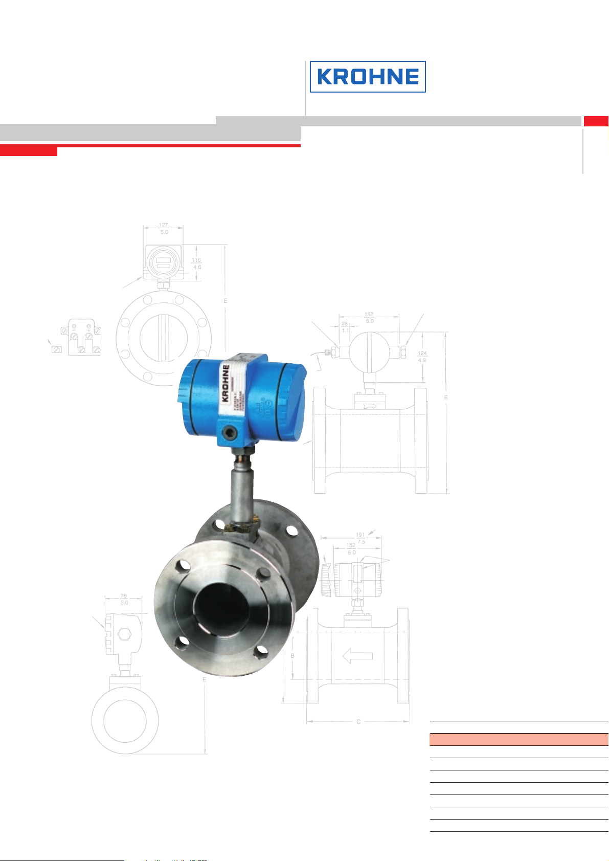
The VFM 3100 F/W-T (Figures 1 and 2) measure fluid (liquid, gas, or
steam) flow rates using the principle of vortex shedding.
Fluid flowing through the VFM 3100 body passes a specially shaped
vortex shedder that causes vortices to form and shed alternately
from the sides of the shedder at a rate proportional to the flow rate of
the fluid. These shedding vortices create an alternating differential
pressure that is sensed by a detector located above the shedder. A
pulsed voltage is generated by the detector with a frequency that is
synchronous with the vortex shedding frequency. This voltage is then
conditioned by the electronic module to produce either a pulse rate
signal or an analog (4 to 20 mA dc) signal.
1.1.2 Fundamental Installation Requirements
Meters shall be installed to meet all applicable local installation regulations, such as hazardous location requirements, electrical wiring
codes, and mechanical piping codes. Persons involved in the installation should be trained in these code requirements in order to ensure that the installation takes maximum advantage of the safety features designed into the VFM 3100.
Figure 2. VFM 3100 W-T Sandwich Body
Figure 1. VFM 3100 F-T Flange Body
Page 7
1.1.3. Standard Specifications
Table 1.
7
Item Specification
Process Temperature Limits -20 and +430 °C (0 and 800 °F)
(a)
Ambient Temperature Limits -40 and +85 °C (-40 and +185°F)
Power Supply Requirements:
Supply Voltage Limits 12,5 and 42 V dc
Supply Current 22 mA dc
Product Safety Specification Refer to instrument data plate for type of certification and
observe aplicable wiring requirements. Electrical certifications
and conditions of certification are listed on page 8.
Flow Rate Requirements Rd = 5000 minimum: Automatic compensation for the
non-linear behavior of vortex shedding in the Rd range
5000 to 20000 is built into the VFM 3100.
This compensation requires the user to input values
for the flowing density and viscosity.
Static Pressure Limits Full vacuum to pressure rating of mating flanges
with maximum operative limit of 10 MPa (1500 psi:
100 bar or kg/(cm
2
) at 24°C (75°F).
VFM 3100 Output
Analog 4 to 20 mA dc into a maximum of 1450 ohms depending
on power supply (refer to graph in Figure 12).
Digital (HART) Digital signal conveyed at a 1200 baud transmission rate.
HART protocol.
Scaled Pulse Isolated 2 wire „contact closure”. Pulse rate
(0 to 100 Hz) proportional to volumetric flow rate.
Scaled Pulse Output Specifications • Isolated 2-wire contact-closure
• Applied voltage limits:
12.5 Vdc minimum
42.0 Vdc maximum
• Maximum „ON” state voltage drop: 0.5 Vdc
• Maximum „ON” state current: 250 mA
• Update rate: 4 Hz
• Maximum „OFF” state leakage current:
0.10 mA @ 12.5 Vdc
0.25 mA @ 24.0 Vdc
0.42 mA @ 42.0 Vdc
• 250 mA short circuit protected
• Reserve polarity protected
Signal Output Combinations 2-Wire Hook-Up
4-20 mA and HART (1200 baud)
3-Wire Hook-Up
4 to 20 mA, HART (1200 baud) and Scaled Pulse
4-Wire Hook-Up
4 to 20 mA, HART (1200 baud) and Scaled Pulse
(a) Maximum temperature limit is a function of sensor type.
Page 8

8
After removing the flowtube from its shipping carton, inspect it for
visible damage. If any damage is observed, notify the carrier immediately and request an inspection report. Obtain a signed copy of the
report form the carrier. The calibration certificate and any other documentation shipped with the VFM 3100 should be separated from the
packing material and held for future reference. Re-install any flange
covers or protective material to safeguard the VFM 3100 until it is installed.
Packing material should be disposed of in accordance with local
regulations. All packing material is non-hazardous and is generally
acceptable to landfills.
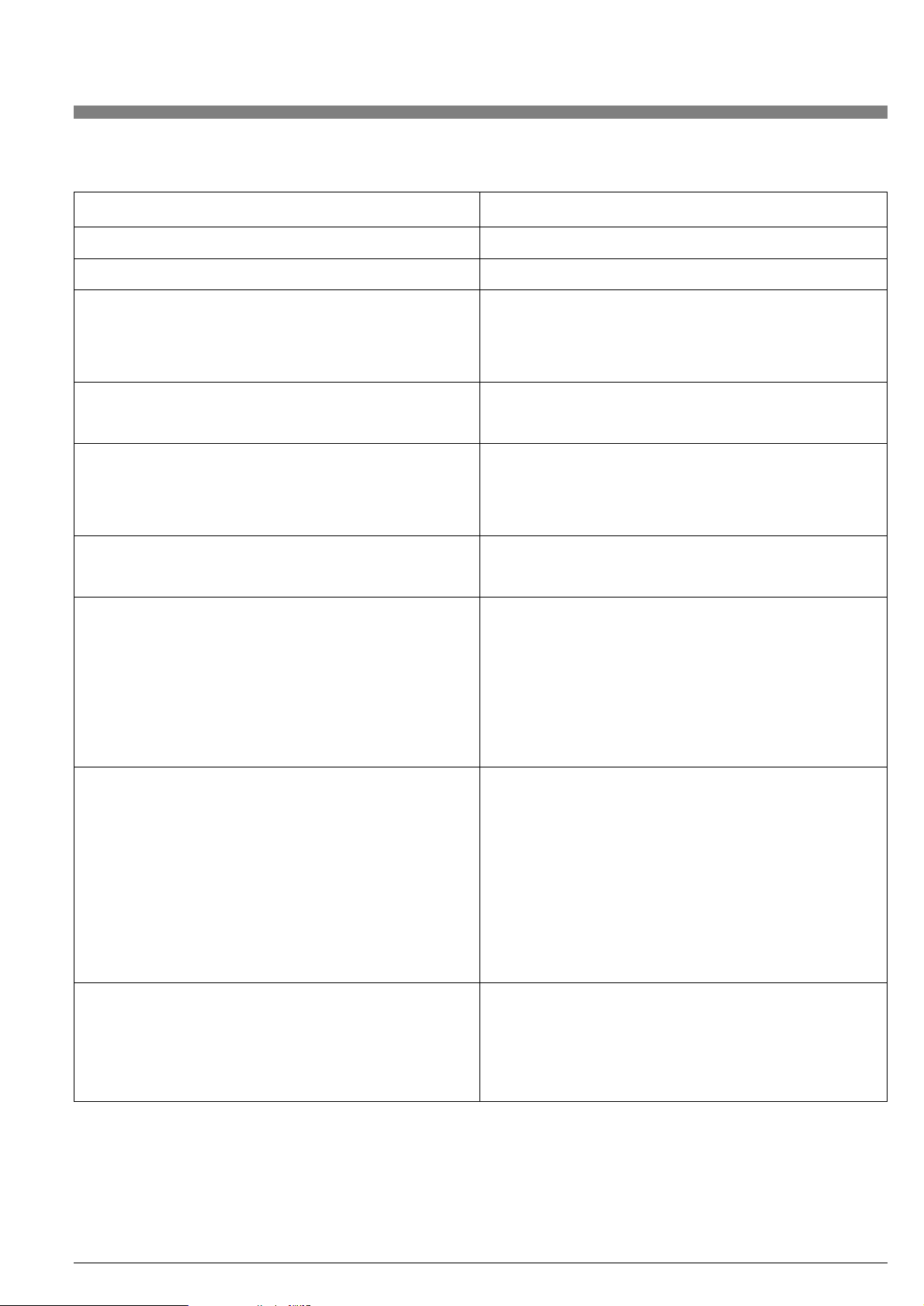
1.1.6. VFM 3100 Identification
The model code is stamped on the data plate as shown in Figure 3
and is digitally readable from the configuration menu.
The Standard Temperature Range sensor is made of 316 stainless
steel and is filled with silicone oil, maximum temperature 200 °C
(400 °F). An optional fill is Fluorolube, maximum temperature 90 °C
(200 °F). The Extended Temperature Range sensor is made of 316
stainless steel and is unfilled, maximum temperature 430 °C (800 °F).
Both standard and high temperature sensors are available made
from Hastelloy.
1.1.4. Electrical Safety Specifications
Table 2.
CSA
intrinsically safe for Class I, Division I,
Groups A, B, C, D; Class II, Division I,
Groups E, F, G: and Class III, Division I
CSA explosionproof for Class I, Division I,
Groups C and D; dust-ignitionproof for Class II
and III, Division I, Groups E, F,
and G; and Class III, Division I.
Suitable for Class I, Division 2,
Groups A, B, C, D; class II, Division 2,
Groups F, G; and Class III, Division 2.
FM intrinsically safe for Class I, II and III,
Division 1, Group A, B, C, D, E, F, and G;
nonincendive Class I, II and III, Division 2,
Groups A, B, C, D, F, and G.
FM explosionproof for Class I, Division 1, Groups C
and D; dust-ignitionproof for Class II and III, Division 1,
Groups E, F, and G; nonincendive Class I, II and III,
Division 2, Groups A, B, C, D, F, and G.
CENELEC intrinsically safe for EEX ib,
Gas Group IIC, Zone 1.
CENELEC flameproof for EEx d (ib), Gas, Group IIC,
Zone 1
Testing Laboratory, Type of Protection,
and Area Classification
Temperature Class T3C at 85°C and
T4A at 40°C maximum ambient.
Limited to Gas Groups C and D when
connected to 33 V, 185 Ω Zener
barrier.
Temperature Class T5.
Temperature Class T3C at 85°C and
T4A at 40°C maximum ambient.
Temperature Class T5.
Temperature Class T4 at 0.8 W.
Temperature Class T5 at 0.5 W.
Temperature Class T6 at 0.3 W.
Temperature Class T6.
Application Conditions
NOTE: These transmitters have been designed to meet the electrical safety descriptions listed in the table above. For detailed information or status of testing laboratory approvals/ certifications,
contact KROHNE.
1.1.5. Unpacking
The VFM 3100 is built to be durable, but it is part of a calibrated
precision system and should be handled as such.
NOTE: VFM 3100 may (depending on pressure rating of flanges
with which they will be used) have a set of centering spacers included. Do not discard these centering spacers. They must be used
to install the VFM 3100 properly.
VFM 3100 with remote-mounted electronics are rugged two-piece
units. A remote cable connection is assembled to the VFM 3100
junction box and electronics housing. The cable may be cut to the
required length per instructions beginning on page 13. Do not allow
the weight of either the flowtube or electronics housing to be supported by the remote cable.
Remove the flowtube from the shipping carton using care to avoid
dropping or otherwise subjecting it to impact, particularly at the
flange or wafer faces. Never put anything through the flowtube for
lifting purposes as damage to the shedder bar may occur.
Page 9
9
Data Label
Certification Label
Measuring
Range Label
Model Code
Serial No.
Productioncode
Maximum Pressure
Style Letter
Temp Limit per
Sensor Option
Complete VFM 3100
Calibration
Factor
Figure 3. VFM 3100 Identification
1.2. Mechanical Installation
There are two mounting arrangements: integral and remote. The
following sections deal with both the integral and remote VFM 3100
arrangements.
1.2.1. Piping Considerations
Effects of Piping on VFM 3100 Performance
The flange size of the adjoining pipe must be the same nominal size
as the VFM 3100. Flanges with a smooth bore, similar to weld neck
flanges, are preferred.
Normal performance data is based on the use of Schedule 40 piping
upstream and downstream of the VFM 3100. If this is not the case,
the actual schedule must be selected from a picklist during configuration and the distance to the disturbance in pipe diameters entered.
This enables the VFM 3100 to automatically compensate for any induced flow effects.
In addition, the bore of the pipe (flange) and VFM 3100 must be
aligned (see "Installation Procedure" on page 12), and the flange
gaskets installed such that they do not protrude into the flow stream.
NOTE: 1. VFM 3100 mounted near pump discharge or suction lines
may be exposed to oscillatory flow that may affect vortex shedding
or product pipe vibration. Also, VFM 3100 mounted near the discharge of a liquid positive displacement pump or near oscillating
control valves may experience severe flow fluctuations that could damage the sensor. To avoid these adverse situations, install the VFM
3100 at least 20 feet or 40 pipe diameters, whichever is larger, from
the disturbance in question.
2. It is good piping practive that the internal surface of the pipe shall
be free from mill scale, pits, holes, reaming scores, rifling, bumps, or
other irregularities for four pipe diameters upstream and two pipe
diameters downstream of the VFM 3100.
Consideration for VFM 3100 Repair
When installing the VFM 3100, consider VFM 3100 repair. The
VFM 3100 should be accessible for servicing. If the flow cannot be
interrupted to replace a sensor, then an isolation manifold should be
mounted on the VFM 3100 before it is installed.
An acceptable and recommended practice is to install bypass
piping so that the entire VFM 3100 may be removed for servicing
(see Figure 4).
Liquid Control Installations
It is recommended for liquid flow that the VFM 3100 be mounted
upstream at least 5 pipe diameters from the control valve and in
vertical installations in the upward flowing leg. This will help to maintain a full pipe and ensure that there is sufficient back pressure to
prevent flashing or cavitation.
30 Pipe Diameters
recommended
5 Pipe Diameters
recommended
Shutoff Valves
Figure 4. Typical Piping Configuration
Page 10

Gas Control Installations
For gas control installations, there are choices for VFM 3100 location
that should be considered. For maximum rangeability, locate the
VFM 3100 30 or more pipe diameters downstream from a control
valve. This will assure maximum velocity at the VFM 3100 and produce the most efficient signal from the sensor.
When the flow is more stable, the VFM 3100 may be mounted a minimum of 5 pipe diameters upstream of the control valve. Pressure
fluctuations often are less on the upstream side of a control valve.
This should be considered as a means to provide the most accurate
density when a flow computer is not used.
The VFM 3100 electronics automatically calculates the effect of upstream piping on K-factor when installation piping data is entered by
user.
Steam Control Installations
For steam control installations, it is recommended that the VFM 3100
be mounted 30 pipe diameters or more downstream of the control
valve. This is particularly useful when measuring saturated steam to
ensure that there is a minimum amount of condensate present at the
VFM 3100.
Pressure and Temperature Taps
NOTE: The inside of the pipe at the pressure and temperature taps
must be free of burrs and obstructions.
Pressure Taps -- For density measurement (when required),
locate the tap 3-1/2 to 4-1/2 pipe diameters DOWNSTREAM
of the VFM 3100. See Figure 5.
NOTE: On a gas installation, the pressure tap should be located on
the top of the pipe. On a liquid installation, the pressure tap (if required) should be located on the side of the pipe. On a steam installation, the pressure tap should be located on the top when the pressure
measuring device (typically a pressure transmitter) is above the
pipeline, and on the side when the measuring device is below the
pipeline. With vertical piping, the pressure tap may be located anywhere around the circumference of the pipeline.
Temperature Taps -- For temperature measurement (when required), locate the tap 5 to 6 pipe diameters DOWNSTREAM of
the VFM 3100. The smallest possible probe is recommended to
reduce flow disturbance. See Figure 5.
10
1.2.2. Installation Position
For optimal performance the locations of the sensor and integral
electronics relative to the piping must be considered. Factors that
influence this decision include process fluid type, ambient temperature, and vibration.
Process Fluid
When using:
Saturated Steam: The electronics housing should be below the
VFM 3100 body, so that the sensor cavity remains filled with condensate.
NOTE: A VFM3100 used on steam should be located downstream
of a control valve.See "Steam Control Installations."
Superheated Steam: The electronics housing should be below the
VFM 3100 body when the steam has less than 10 °F (5.6 °C) superheat. The housing should be above the VFM 3100 body when the
superheat is more than 10 °F and no condensate will be forming on
the sensor. An isolation valve may be used in superheated steam
applications with adequate insulation.
Gas: The electronics housing may be above or below the VFM 3100
body. The normal recommended position of the electronics housing
is above the VFM 3100 body.
Liquid: For a liquid with solid particles, the electronics housing
should be above the VFM 3100 body. Care should be taken so that
entrapped air does not accumulate in the sensor cavity. For a clean
liquid, the electronics housing may be mounted below the VFM 3100
body. Care must be taken if there is any sediment or fine dirt, that the
particles do not accumulate in the sensor cavity. A VFM 3100 used
on liquid should be mounted upstream from a control valve.
VFM 3100 may also be mounted with the electronics housing positioned to the side. This ensures escape of entrapped air and minimizes sediment accumulation.
The above considerations are summarized in Table 3 for single and
dual measurement VFM 3100 with and without isolation valves.
1.2.3. Ambient Temperature
Ambient temperature limits must be observed per specifications.
However, if the electronic housing is above the ambient temperature
limit (85 °C, 185 °F), the VFM 3100 may be mounted with the electronic housing located to the side to aid the cooling of the electronic
module. The bottom conduit connection shoud be used (the top one
plugged) to avoid possible accumulation of condensate at the terminal block.
1.2.4. Vibration
The vortex shedder axis should be oriented to reduce or, in some cases virtually eliminate, vibration influence. Positioning VFM3100 so
that vibrations are parallel to sensor diaphragms will minimize effect
of vibrations.
Pressure Tap
Temperature Tap
Direction of Flow
Figure 5. Pressure and Temperature Tap Locations
Page 11
11
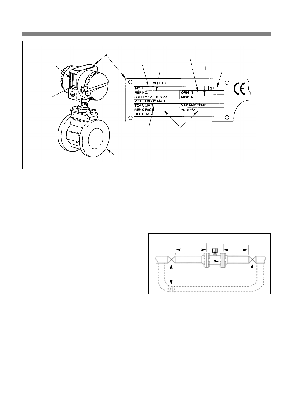
Table 3. VFM 3100 Mounting Arrangements
Single Measurement (with and without isolation valves)
Housing Above Pipe
GAS Recommended mounting.
STEAM Recommended for super-heated steam with adequate
insulation. Not recommended for saturated steam.
LIQUID Adequate self-purging. Recommended mounting.
Isolation Valve may cause temporary start-up error
due to entrapped air.
Vertical Pipe
GAS Recommended mounting.
STEAM Recommended for super-heated steam with adequate
insulation. Not recommended for saturated steam.
LIQUID Adequate self-purging. Recommended mounting.
Housing Below Pipe
GAS Recommended for clean applications only.
STEAM Not recommended for super-heated steam.
Recommended for saturated steam.
LIQUID Recommended when self-purging is important.
Housing Beside Horizontal Pipe
GAS Recommended mounting.
STEAM Not recommended for saturated steam. Recommended
for superheated steam provided the pipe is adequately
insulated.
LIQUID Adequate self-purging, recommended mounting.
Housing to the Side and Below Horizontal Pipe
Note: Requires flanges with eight or more bolts
GAS Not recommended
STEAM Not recommended
LIQUID Recommended.
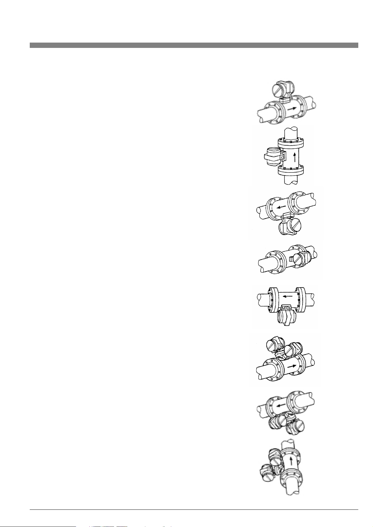
Dual Measurement (with or without isolation valves)
Housing Above Pipe
GAS Recommended mounting.
STEAM Recommended for super-heated steam with adequate
insulation. Not recommended for saturated steam.
LIQUID Not self-purging. May cause errors at startup.
Not recommended for batch operations.
Vertical Pipe
GAS Recommended mounting.
STEAM Recommended for super-heated steam with adequate
insulation. Not recommended for saturated steam.
LIQUID Adequate self-purging. Recommended mounting.
Housing Below Pipe
GAS Not recommended.
STEAM Not recommended for super-heated steam.
Recommended for saturated steam.
LIQUID Self-purging. Recommended for batch operations.
Page 12

12
1.2.5. Installation Procedure
VFM 3100 F–Flanged Body
• Gaskets are required and must be supplied by the user.
Select a gasket material suitable for the process.
• Insert gaskets between body of VFM 3100 and adjacent
flanges. See Figure 6. Position gaskets so that ID of each
gasket is centered on ID of VFM 3100 and adjacent piping.
CAUTION:
• Verify that the ID of the gaskets is larger than that of the VFM
3100 bore and pipe and that they do not protrude into the
VFM 3100 entrance or exit. Accuracy of the measurement will
be affected.
• Gaskets will not prevent flanges from being wetted by process
fluids.
NOTE: When installing new flanges in the process piping and the
VFM 3100 is used as a gauge to set the flanges, the inside diameter
of the VFM 3100 must be protected from weld splatter. It is recommended that a solid sheet of gasketing be installed at each end of the
VFM 3100 during welding. Remove this sheet and install flange gasket after welding. Remove any splatter in either the pipe or the VFM
3100 as this could affect VFM 3100 accuracy.
• Visually inspect for concentricity of mating flanges.
• Tighten bolts in accordance with conventional flange bolt
tightening practice (i.e., incremental and alternate tightening
of bolts).
VFM 3100 W– Sandwich Body
For optimal performance, the sandwich body VFM 3100 should be
centered with respect to the adjoining pipe. Normally, this requires
the use of centering fixtures that are supplied with the VFM 3100.
NOTE: Centering fixtures are not required for meters with ANSI
Class 150 flanges.
Two types of centering fixtures are presently in use; the older centering sleeves and the newer hex-nut spacers. The VFM 3100 may
come with either type of fixture. Most meter sizes have two centering
fixtures (two sets in the case of the hex-nut spaceres), but some larger sizes may have twice this number, two for each side.
• See Figure 7. Insert the first stud through the downstream
flange at one of the lower holes, through the centering sleeves
or two hex-nut spacers, and then through the upstream flange.
Place the nuts on both ends of the stud but do not tighten.
• Using the remaining centering sleeve or hex-nut spacers,
repeat Step 1 at the lower hole adjacent to the first.
• Set the VFM 3100 between the flanges. For centering with the
hex-nut spacers, rotate spacers to the thickness that centers
the VFM 3100.
NOTE: By rotating the hex-nut spacers to the correct thickness, you
can center the VFM 3100 to any type of flange.
• Gaskets are required and must be supplied by the user.
Select a gasket material suitable for the process fluid.
• Insert gaskets between body of VFM 3100 and adjacent
flanges. Position gaskets so that ID of each gasket is centered
on ID of VFM 3100 and adjacent piping.
CAUTION: Verify that the ID of the gaskets is larger than that of
the VFM 3100 bore and pipe and that they do not protrude into the
VFM 3100 entrance or exit.
NOTE: If welding of flanges to the process piping is required, protect
the VFM 3100 from weld splatter, which could affect VFM 3100
accuracy. It is recommended that a solid sheet of gasketing be installed at each end of the VFM 3100 during welding. Remove this sheet
and install flange gasket after welding.
• Visually inspect for concentricity of mating flanges.
• Install the rest of the studs and nuts and tighten the nuts in
accordance with conventional flange bolt tightening practice
(i.e., incremental and alternate tightening of bolts).
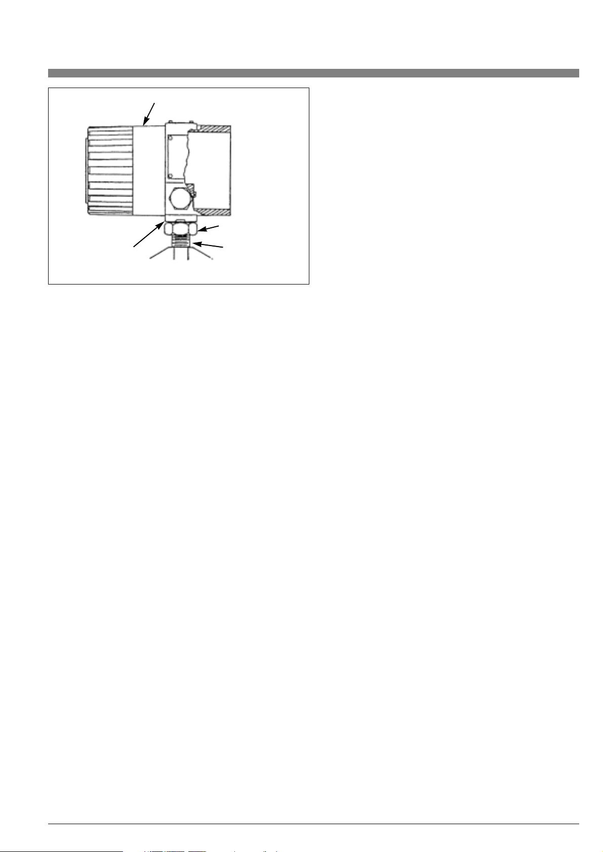
1.2.6. Repositioning the Electrical Housing
The VFM 3100 housing may be repositioned up to a maximum of
270°C from its original position by rotating the electrical housing.
WARNING: Stops are incorporated in the housing design. Do not
remove the stops as further rotation from the 270°C maximum may
cause damage to the sensor wires. Additionally this may violate safety code requirements for explosion-proof thread engagement in
hazardous locations.
• Unscrew housing locknut to bottom of thread. See figure 8.
• Square locking plate should slip down on shaft. If it does not,
pry out with scewdriver.
• Rotate electrical housing to desired position.
See Warning on page 12.
• Note recess on bottom of electrical housing into which the
locking plate fits. Screw the locking nut hand tight making sure
locking plate fits into recess on bottom of electrical housing.
• Secure the locknut firmly using a wrench.
Gasket
Gasket
VFM 3100
Gasket
Gasket
Install centering
fixtures on
adjacent lower
studs of flange
VFM 3100
2 hex-nut spacers
per side (not required
with class 150)
Hex-nut alignment device
(not required with class 150)
Centering sleeve
(not required with
class 150)
Figure 6. VFM 3100 F Installation
Figure 7. VFM 3100 W Centering (using Spacers OR Sleeves)
Larger meters
have 2 centering
fixtures per side
Page 13
1.2.7. VFM 3100 with Remote Electronic Module
The purpose of the remote electronic module is to allow for separation of the VFM 3100 body and the electronics housing.
This VFM 3100 consists of:
• An electronics housing mounted to a pipe or wall mounting
bracket with up to 15 m (50 ft) of interconnecting cable attached.
• A VFM 3100 body with junction box. The junction box contains
a preamplifier assembly. Refer to Figure 9.
• 1/2 NPT conduit connections are provided on both the housing
and the junction box.
NOTES:
• Mount the VFM 3100 so that the junction box is serviceable.
• The cable is prewired to the junction box to ensure proper
grounding of the shield. It is recommended not to disconnect
the cable from the junction box.
• If the cable must be disconnected, make sure the end labeled
"VFM 3100 End" is positioned at the junction box end.
• If the cable is to be shortened, refer to Table 2 for re-dressing
cable ends.
Installing the Remote Electronics
WARNING: For optimum VFM 3100 performance, the remote signal
cable must be prepared and connected following the procedures
outlined below.
To install the remote electronics as shipped, execute the following
procedure:
• Mount the VFM 3100 as described in the preceding section. Be
sure to mount the VFM 3100 so that the junction box is serviceable.
• Mount the housing. The bracket assembly supplied with the housing may be mounted directly to a wall or to a 2-inch pipe stand.
• Mount the housing close enough to the VFM 3100 so that the
supplied cable will reach between the VFM 3100 and the housing.
To install remote electronics that must be separated, disconnect the
remote signal cable at housing end as described below.
It is not recommended that you disconnect the VFM 3100 end
(junction-box end).
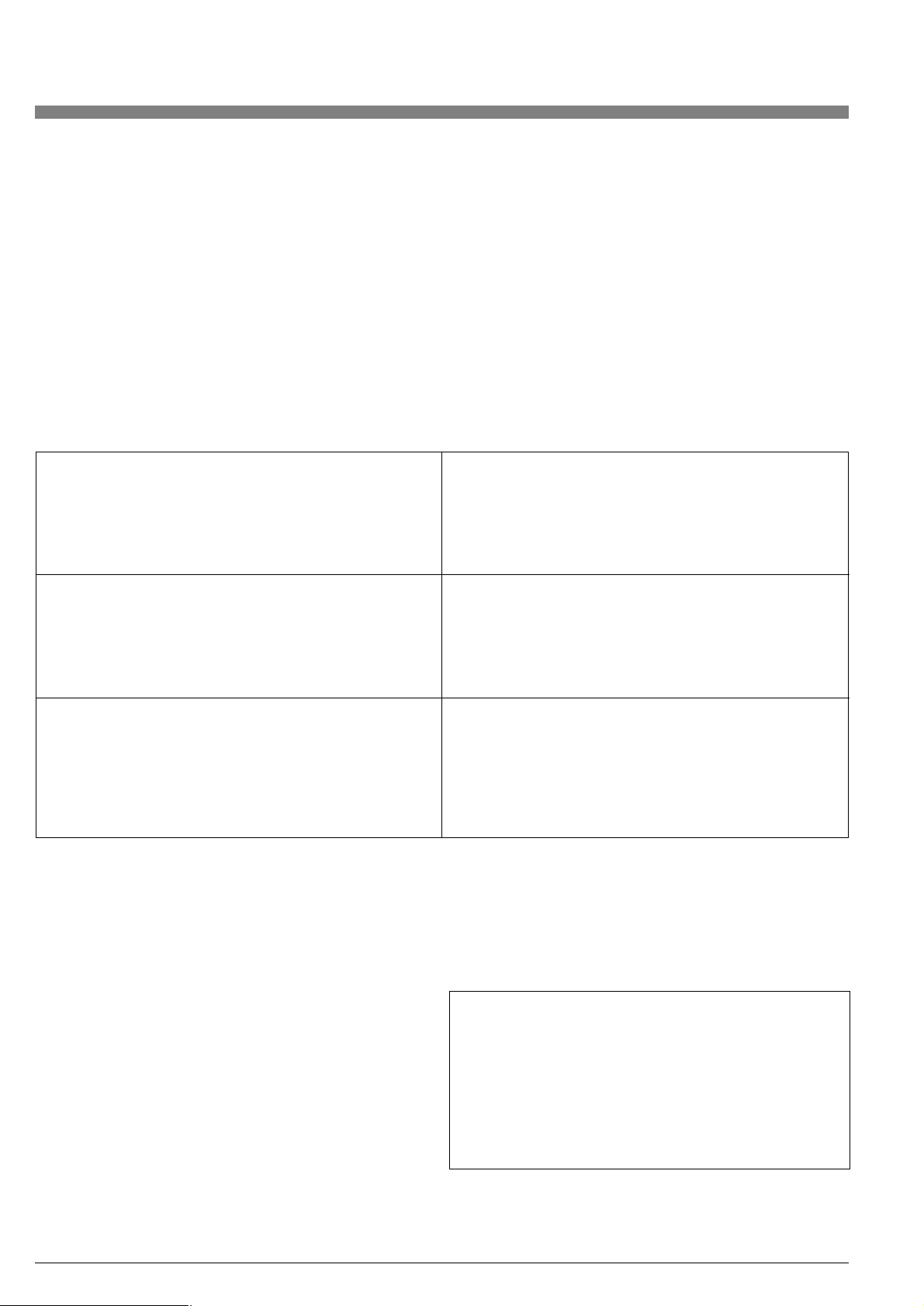
• Remove electronic compartment threaded cover.
• Unscrew the two captive screws, one on each side of the
electronic module.
• Pull out electronic module far enough to disconnect the
remote signal cable.
• Disconnect the four remote signal wires from the four position
terminal block on rear of the electronic module. See Figure 9.
• Unscrew knurled nut, pull it back onto cable jacket, also pull
rubber bushing onto the cable jacket. Leave these parts on the
cable jacket as they will be used when reconnecting the cable.
• Mount the VFM 3100 as described in the preceding section. Be
sure to mount the VFM 3100 so that the junction box is serviceable.
• Mount the housing close enough to the VFM 3100 so that the
supplied cable will reach between the VFM 3100 and electronic
housing.
• Mount the electronic housing. The bracket assembly supplied
with the housing may be mounted directly to a wall or a 2-inch
pipe stand.
Interconnection Wiring for Remote Electronics
Installation without Conduit:
If the VFM 3100 and electronic housing were NOT separated during
installation, the interconnection wiring is complete.
NOTE: Oxygen cleaned meters are shipped separated.
If Housing End Is Disconnected:
If the VFM 3100 and electronic housing were separated during installation, follow the procedures below for interconnection wiring.
• Make sure the knurled nut and rubber bushing are on the cable
jacket. Orient the cable so that the end labeled "VFM 3100 End"
is positioned at the VFM 3100 junction box and the "Electronics
End" is positioned at the remote electronics housing.
• If the pre-dressed cable does not look as shown in Table 6, prepare it following the instructions for dressing electronic housing
end of remote signal cable in Table 6 on page 17.
• Take the prepared cable, taking care not to damage the copper
braid, and push it into the connector at bottom of the electronic
housing, as shown in Step 1 of Table 6 on page 17 until it comes
to a stop.
• Ensure that the remote signal cable is pushed in all the way, until
the outer jacket bottoms out inside the connector. Push the
rubber bushing into position, until it sits snug inside the connector, as shown in Step 2 of Table 6 on page 17.
• Tighten the knurled nut on the connector to create a compression
fit for a good seal.
• Inside the electronic housing, connect the four remote signal wires to the color coded 4-position terminal block on the rear of the
electronic module. See Figure 9 on Page 16.
• Ensure that the remote signal and loop power wires are tucked
under the electronic module. Taking care not to pinch the wires,
place the module in housing over mounting screws. Tighten the
two captive mounting screws.
• Replace threaded housing cover tightly. This will prevent moisture
or other contaminants from entering the compartment.
13
Electrical housing
with digital display/configurator
Locknut
Connector
Locking plate
Figure 8. Repositioning the Electrical Housing
Page 14

For installations where the provided pre-dressed remote signal cable
is not used, both ends of the cable being used must be prepared per
the instructions in Tables 4 and 5 of document. The cable must be
connected at both ends per instructions on Tables 6 and 7 on Pages
14
17 and 18. Terminate wires at J-Box following Figure 9 on Page 16.
At housing end, wires should be terminated at 4-position terminal
block on rear of electronic module as shown in Figure 9.
1. Slide the knurled nut and then the rubber bushing onto
outer jacket of cable as shown at right. Next, remove outer
polyethylene jacket of cable to dimension shown.
2. Cut and remove braided copper shield to dimension shown
at right. This will expose the barrier (plastic) tape and foil
mylar that encloses the conductors.
3. Cut and remove the barrier tape, foil mylar and fillers to
dimension shown at right. This will expose two twisted
pairs of conductors (brown-yellow, orange-red) and an
uninsulated drain wire. The barrier tape under the copper
braid prevents the drain wire from shorting to the copper
braid shield.
4. Trim the uninsulated drain wire to dimension shown at right.
To expose bare conductors for termination, cut and strip
ends of the two twisted pairs to dimension shown.
5. Fold drain wire back onto the copper braid as shown at
right. Label outer cable jacket „VFM 3100 End” to avoid
confusion during installatin. Cable is now ready for
installation.
VFM 3100 End (Junction Box End) Procedures
Knurled nut
Outer polyethylene
jacket
Outer polyethylene
jacket
Rubber bushing
191 mm (7.5 in)
Copper braid
Knurled nut
Rubber bushing
25 (1.0) 165 mm (6.5 in)
Copper braid
Barrier tape and
foil mylar
Outer polyethylene
jacket
Knurled nut
Rubber bushing
Copper braid
Barrier tape and
foil mylar
Knurled nut
Outer polyethylene
jacket
Label cable
jacket
Rubber bushing
Copper braid
Barrier tape and foil mylar
25 (1.0) 165 mm (6.5 in)
Two twisted pairs
Uninsulated drain wire
Outer polyethylene
jacket
Knurled nut
Rubber bushing
Copper braid
do not tape
6.4 mm (.25)
cut and strip
4 places
25 (1.0) 165 mm (6.5 in)
25 (1.0)
Two twisted pairs
Uninsulated drain wire
Bare conductor (4 places)
Two twisted pairs
Uninsulated drain wire
VFM 3100
end
Table 4. Preparation of Remote Signal Cable
Page 15
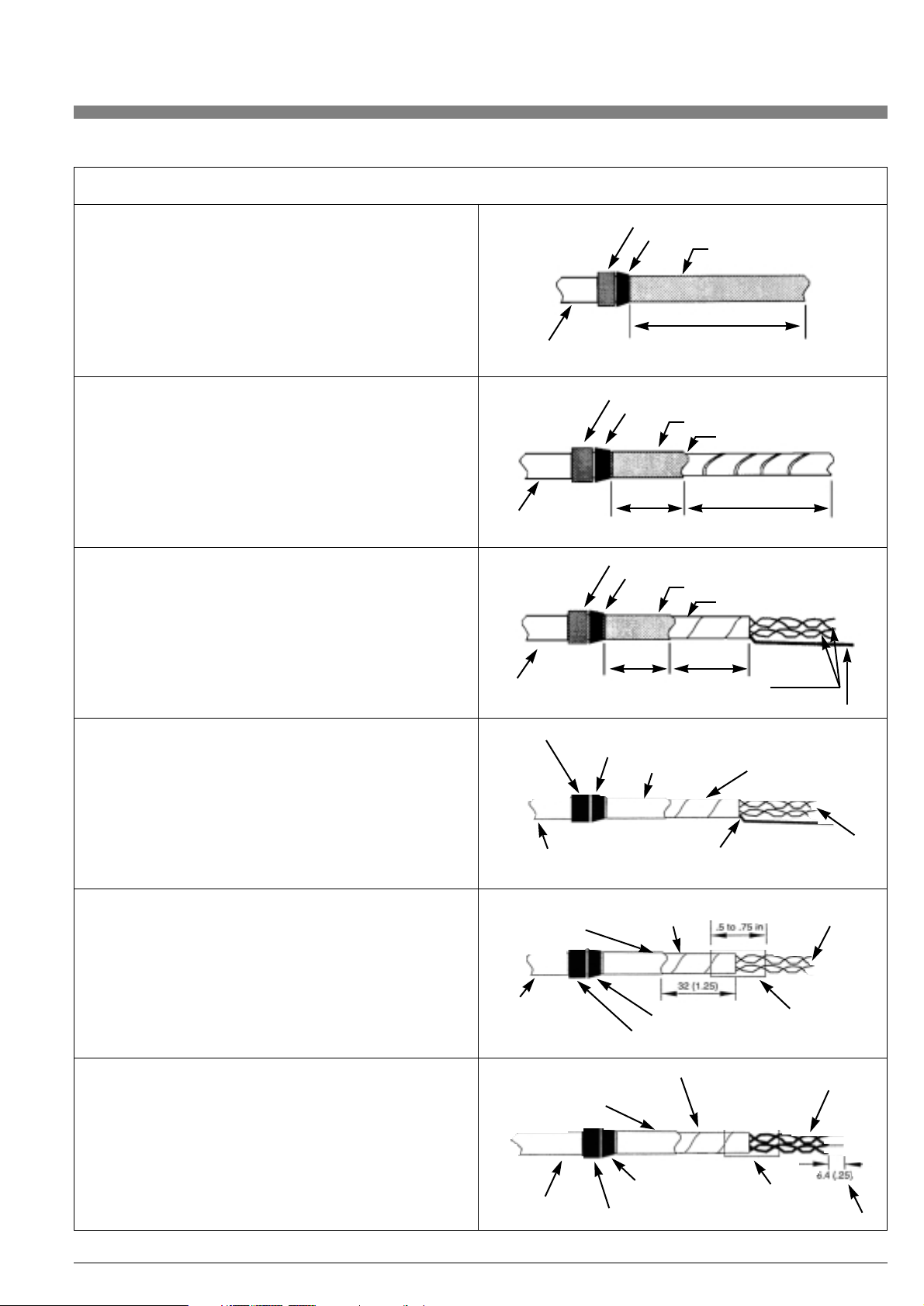
Table 5. Preparation of Remote Signal Cable (Electronics End)
15
1. Slide the knurled nut and then the rubber bushing onto
outer jacket of cable as shown at right. Next, remove outer
polyethylene jacket of cable to dimension shown.
2. Cut and remove braided copper shield to dimension shown
at right. This will expose the barrier (plastic) tape and foil
mylar that encloses the conductors.
3. Cut and remove the barrier tape, foil mylar and fillers to
dimension shown at right. This will expose two twisted
pairs of conductors (brown-yellow, orange-red) and an
uninsulated drain wire. The barrier tape under the copper
braid prevents the drain wire from shorting to the copper
braid shield.
Electronics End (Electronic Housing End) Procedures
Outer polyethylene
jacket
Outer polyethylene
jacket
Outer polyethylene
jacket
203 mm (8.0 in)
Knurled nut
Rubber bushing
Copper braid
178 mm (7.0 in)25 (1.0)
Knurled nut
Rubber bushing
Copper braid
Barrier tape and foil mylar
Knurled nut
Rubber bushing
Copper braid
Barrier tape and foil mylar
Two twisted pairs
Uninsulated drain wire
25 (1.0) 40 (1.5)
4. Cut off drain wire at end of barrier tape and foil mylar as
shown ar right. It is not used at this end.
5. Apply shrink tubing or electrical tape to end of barrier tape
and foil mylar at location shown at right. Note that the shrink
tube or tape covers end of barrier tape and mylar as well as
a portion of the 2 twisted pairs of wires. This will prevent the
barrier tape and foil mylar from unwrapping.
6. Cut and strip ends of the two twisted pairs to dimension
shown at right. Label outer cable jacket ”Electronic End”
to avoid confusion during installation. Cable is now ready
for installation.
Knurled nut
Copper braid
Barrier tape and foil
mylar
cut off
here
Two twisted pairs
Outer polyethylene
jacket
Knurled nut
Knurled nut
Rubber bushing
Rubber
bushing
Shrink tube or
electrical tape
cut and strip 4 places
Copper braid
do not tape
Copper braid
do not tape
Label cable
jacket
Electronic
end
Barrier tape
and foil mylar
Barrier tape and foil mylar
Shrink tube or
electrical tape
Two twisted pairs
Outer polyethylene
jacket
Two twisted pairs
Rubber bushing
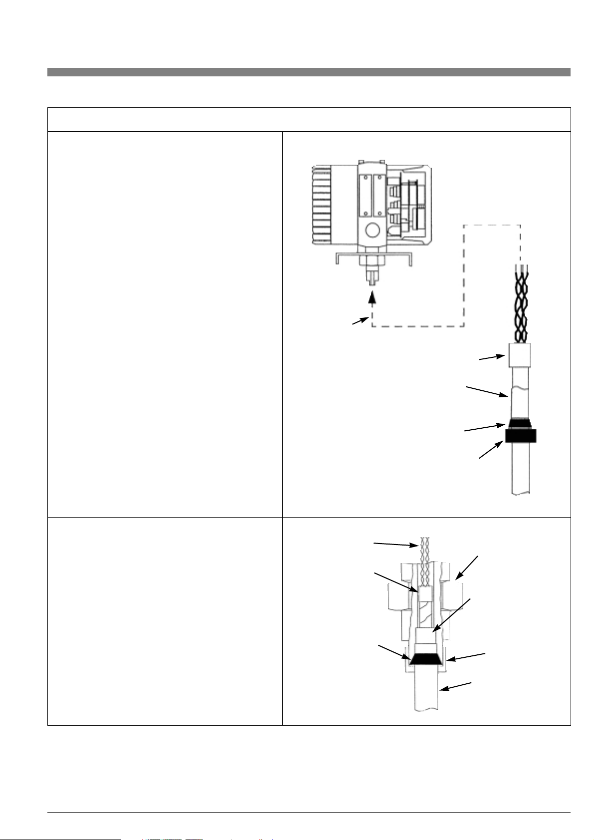
Page 16

16
Electronic module
(see detail „A”)
See table 7 for details
of this connection
Disconnect
this end when
installing.
See table 5
for dressing of
cable at this end.
Outside braid makes contact to
housing. Braid is compressed for a
good electrical connection.
See table 6 and 7.
1/2 inch conduit may be connected
directly to connectors via 3-piece
union/coupler.
Cable must be pushed into stainless steel
fittings when installing compression nuts
to ensure that the braid is properly seated
for a good electrical connection (both ends).
See tables 6 and 7.
See table 5 for
dressing of cable
at this end.
VFM 3100 body.
External earth (ground)
connection screw –
cenelec flameproof only.
Pre-assembled and dressed
junction box
Braided shield and drain wire must
be in contact at this end of cable.
Note: do not disassemble to install.
Remote
cable
Output
signal
wires
brown
red
orange
yellow
Detail “A”
Figure 9. Overall View of Remote Mounted VFM 3100
Page 17
17
1. Take electronics end of prepared remote signal
cable and align it as shown at right. Ready for
assembly.
2. As shown in the diagrams at right, push the
prepared cable assembly into the remote
connector. Push until the cable bottoms out
(cannot be pushed in any furher). Push rubber
bushing into position and tighten the knurled
nut onto the remote connector to create a
good compression fit.
Electronics End (Electronic Housing End) Procedures
Push cable
assembly into
connector
Shrink tube or tape
Prepared remote
signal cable
(electronics end)
refer to table 3
Rubber bushing
Knurled nut
Electronics
end
Electronics
end
2 twisted pairs
Remote
connector
Compression fit of
copper braid in contact
with connector for
shielding
Knurled nut
Remote signal cable
Shrink tube or
electrical tape
Rubber bushing
Table 6. Connection of Remote Signal Cable
Page 18
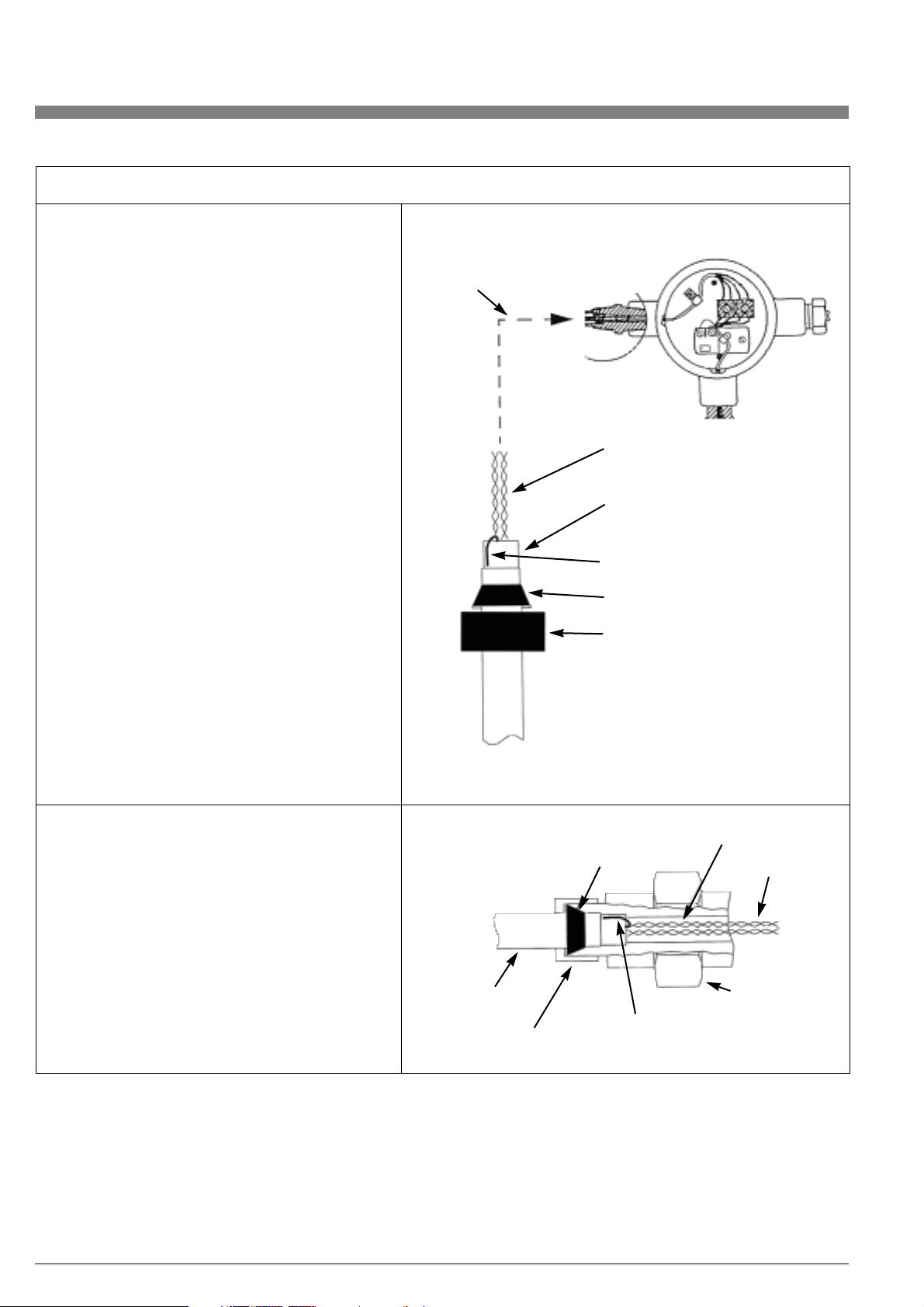
18
1. Take VFM 3100 end of prepared remote signal
cable and align it as shown at right. Ready for
assembly.
2. As shown in the diagrams at right, making
sure that the drain wire is folded back against
the copper braid, push the cable assembly
into the remote connector. Push until the cable
bottoms out (cannot be pushed in any further).
Push rubber bushing into position and tighten
the knurled nut onto the remote connector to
create a good compression fit.
VFM 3100 End (Junction Box End) Procedures
VFM 3100
end
Push cable assembly
into connector
2 twisted pairs
Prepared remote
signal cable (VFM 3100 end)
refer to table 2
Drain wire folded back
Rubber bushing
Knurled nut
Knurled nut
Remote
signal cable
VFM 3100
end
Rubber bushing
Shrink tube or
electrical tape
2 twisted pairs
Junction box
connector
Compression fit of drain wire
and copper braid in contact
with connector for shielding
Table 7. Connection of Remote Signal Cable (Electronics End)
Page 19

19
Installation with Conduit:
• The junction box is pre-wired. A conduit box or conduit may be
mounted directly to the 1/2 NPT connection at the remote housing. A box or a standard 3-piece union/coupler may be mounted
directly over the knurled nut. Do not disassemble pre-wired
connection at junction box.
• Run remote cable to the remote electronic module housing via
conduit. If required, prepare cable as shown in Table 5. Feed it into
the housing following Steps in the procedure for "Interconnection
Wiring for Remote Electronics" on page 13 and Table 6 on page 17.
• Mount conduit box or conduit to the 1/2 NPT connector directly
or via a 3 piece union/coupler, if necessary. Make connection to
the 1/2 NPT connector after the knurled nut has been tightened
to provide a compression fit for the cable. Refer to Table 6 on
page 17.
• At this point, follow Steps in the procedure for "Installation
Without Conduit" on page 13.
CENELEC Flameproof Version:
• The junction box side of the remote confirguration is pre-wired.
Add flameproof cable gland or E-Y fitting and conduit directly
to the special Foxboro adapter or via an approved CSA/UL 3piece union/coupler, if necessary. For this reason, the second
conduit plug is fitted with a grounding screw (see Figure 9).
NOTE: CENELEC certification requires that an infallible physical
earth (PE) connection be made to the junction box.
• Run the remote cable to the remote electronic module housing
via cable trays or conduit.
• Place knurled nut and rubber bushing over the cable as shown
in Table 5 on page 15.
• Prepare the remote cable as shown in Table 5.
• Remove the locked electronic module component cover from
remote electronic module housing. Unscrew captive mounting
screws and remove the electronic module without disconnecting
loop power wiring.
• Feed prepared remote cable into the electronics housing through
connector at bottom of housing. Push it in until the outer jacket
bottoms out inside the connector. See Table 6.
• Ensure that the cable is pushed in all the way and then push the
rubber bushing into position. Tighten the knurled nut to create a
compression fit. See Table 6.
• Inside the remote electronics housing, connect the four wires of
the remote cable to the 4-position terminal block on the rear of
the electronic module.
Follow the color-coded label. See Figure 9 on Page 16.
• Ensure that the excess remote cable and loop power wires are
tucked in under the electronics module. Without pinching, place
the module back into the housing and tighten the mounting
screws.
• Replace the housing cover tightly to prevent moisture and other
contaminants from entering and then lock it in place.
1.3. Field Termination
The following section addresses Wiring, conduit, and Earth (Ground)
Connection details.
1.3.1. Conduit Connections
NOTE: The wiring installation shall be in accordance with the local or
national regulations applicable to the specific site and classification
of the area.
The electronics housing has an electronic module compartment and
a field terminal compartment. It also provides 1/2 NPT conduit openings for access from either side of the VFM 3100 and for ease in
wiring to the field terminals. See Figure 10.
NOTE: One conduit opening contains a threaded plug. Do not discard this plug.
Remove the field terminal compartment cover (shown in Figure 10)
to make electrical connections. Keep the electronic module compartment cover closed to ensure protection for the electronic module
and to prevent moisture and atmospheric contaminants from entering the compartment.
There are three wiring combinations that depend on how the
VFM 3100 is to be used.
2-Wire Hook-up
4 to 20 mA and HART (1200 baud)
3-Wire Hook-up
4 to 20 mA, HART (1200 baud) and Scaled Pulse
4-Wire Hook-up
4 to 20 mA, HART (1200 baud) and Scaled Pulse
Two-Wire Hook-up
A dc power supply must be used with each transmitter and receiver
wiring loop to supply power for the mA signal. The dc power supply
may be either a separate signal unit, a multiple unit supplying power
to several transmitters, or built into the receiver. Connect the supply
and receiver loop wiring (0.50 mm2 or 20 AWG typical) to the
terminals in the field-terminal compartment of the transmitter,
as shown in Figure 11.
Electronic module
compartment
Electrical conduit
opening
Field terminal
compartment
Figure 10. Electronics Housing
Page 20

20
Twisted pair wiring should be used to prevent electrical noise from
interfering with the dc current output signal. In some instances,
shielded cable may be necessary. Earthing (grounding) of the shield
should be installed at one point only (at the power supply). Do not
earth (ground) the shield at the transmitter.
Transmitter connection polarities are indicated on the terminal block.
If the loop is to contain additional instruments, install them between
the negative terminal of the transmitter and the positive terminal
of the receiver, as shown in Figure 11.
Power Supply and External Load
The required loop power supply voltage is based on the total loop
resistance. To determine the total loop resistance, add the series
resistance of each component in the loop (do not include transmitter). The required power supply voltage can be determined from
Figure 12.
The transmitter will function with an output load less than 250 ohms,
provided that a configurator is not connected to it. Connecting a
configurator to a loop with less than 250 ohms may cause communication problems.
As an example, for a transmitter with a loop resistance of 500 ohms,
referring to Figure 12, the minimum power supply voltage is 22 V dc,
while the maximum power supply voltage is 42 V dc. Conversely,
given a power supply voltage of 24 V dc, the allowable loop resistance is from 200 to 565 ohms.
NOTES:
• The power supply must be capable of supplying 22 mA.
• Power supply ripple must not allow the instantaneous voltage
to drop below 12.5 V dc at the transmitter.
• The recommended minimum load is 250 ohms.
Case ground
terminal (earth)
Power
supply
Receiver
Additional
receivers
in loop.
250 ohm min load
required for
communication
Hart communicator.
Connect to loop to configure transmitter.
Two 1/2 NPT conduit connections are provided
(on opposite sides). Insert plug in connection
not used.
Terminal block
Figure 11. Installation Wiring -4-20 mA Output (Two-wire)
Figure 12. Load Requirements
Recommended supply voltage
and load limits
VDC
24
30
32
Load (OHMS)
250 and 565
250 and 860
250 and 960
Operating area
See note below
Supply voltage, V dc
Output load,
Min.
Load
Page 21

A dc power supply must be used with each transmitter and receiver
wiring loop to supply power for the transmitter. The dc power supply
may be either a separate signal unit, a multiple unit supplying power
to several transmitters, or built into the receiver.
Connect the supply and receiver loop wiring for pulse out (0.50 mm
2 or 20 AWG typical) to the terminals in the field-terminal compartment of the transmitter, as shown in Figure 13. To use this type of
3-wire hookup, the blue and green terminals on the back of the
module must be shorted.
A resistor is required to produce a voltage drop for proper operation
of the counter. A 680 ... 2 W resistor is recommended for most coun-
ters.The pulse signal can cause interference to signals in adjacent
signal cables. In some instances, shielded cable may be necessary.
Earth grounding of the shield should be at one point only (at the power supply). Do not ground the shield at the transmitter. Transmitter
connection polarities are indicated on the terminal block.
Power Supply and Load
The power supply voltage must be between 12.5 and 42 V dc. The
pulse "OFF" state current is a maximum of 0.42 mA at 42 V dc. In the
"ON" state, the pulse output is short circuit protected for 250 mA.
Four-Wire Hook-up
Two separate loops are required when using the scaled pulse output
in the four-wire hook-up arrangement. Each loop requires its own
power supply. Refer to Figure 14.
Select the resistor so that the current through the contact closure
does not exceed 250 mA.
Wiring may be run in conduit or in wireways. The wiring must meet all
applicable local standards such as hazardous location requirements
and electrical wiring codes. Signal wires should not be run in the
same conduit as power wires. Shielded twisted pair wiring is recommended.
21
Three-Wire Hook-up (See Figure 13)
Scaled Pulse Output
This wiring is primarily used to retrofit VFM3100 transmitters that
were wired as pulse only transmitters for totalization. This wiring is
typically for retrofitting existing installations. Configure the transmitter
for pulse output. Refer to the section on changing the configuration
beginning on page 23.
For new installations, a four-wire hook-up is recommended
for scaled pulse operation to improve communication integrity.
Red (+)
Output signal wires
Back of module
electronics side
Yellow (P)
Terminal block
Case ground
terminal
(earth)
250 OHM min.
load required for
communication
Hart communicator. Connect to loop
to configure transmitter.
Power
supply
Counter
680 OHM
Blue (-)
Shorting wire across
B and G
Sensor/preamplifier wires
Figure 13. Installation Wiring – Pulse Output (Three-wire)
Case ground
terminal (earth)
Terminal block
4-20 mA loop
680 Ω
Power
supply
Counter
Scaled pulse loop
Figure 14. Installation Wiring (Four-wire)
Page 22
22
2. Operating the VFM 3100
2.1 Introduction
Communication with the VFM 3100 is carried out using the HART
Model 275 Communicator or the optional Local Digital Display/Configurator. General instructions for using the HART Configurator can
be found in MAN 4250, HART Communicator Product Manual.
Vortex-specific instructions for using the HART configurator will be
found in chapter 8 of this document. Complete instructions for using
the Local Configurator will be found in chapter 9.
Note: For proper communication with VFM 3100, the HART
configurator must contain the DD for the KROHNE VFM 3100.
This DD is available from KROHNE, or any other authorized HART
Foundation source.
2.2 Passwords
The transmitter itself has no password. Rather, security measures,
i.e., the ability to access functions such as calibration, configuration,
and testing, are associated with the configurators used to communicate with the transmitter. The HART Communicator has no security
measure other than access to the device itself. The Local Digital Display/Configurator requires a password that is user definable. See
chapter 9.
2.3 Configuration Database
In order to function, the transmitter requires specific embedded
information, termed the “configuration database”. The parameters in
this database are listed in Table 8, and defined in chapter 9.
Each VFM 3100 is shipped from the factory with an operating configuration database; however, the VFM 3100 will not provide an accurate measurement if the configuration does not fit the application.
Be sure to check the configuration of each VFM 3100 prior
to start-up!
Flowtube Parameters
Model Code
Meter Body Serial Number
Reference K-Factor
Identification Parameters
Ta g
Descriptor
Date
Message
Polling Address
Transmitter Options
Flow Units
Total Units
Noise Rejection
Signal Conditioning
Low Flow Correction
Low Flow Cut-In
Process Fluid Parameters
Fluid Type
Process Temperature
Process Density
Base Density
Process Viscosity
Application Parameters
Mating Pipe
Piping Configuration
Upstream Distance
Custom K-factor Bias
Upper Range Value
Output Options
Damping Value
Pulse Output
AO/PO Alarm Type
Table 8. Configuration Database
Ta g
Fluid Type
Flow Units
Total Units
Process Temperature (value and units)
Process Density (value and units)
Base Density (if applicable; value)
Process Viscosity (if applicable; value and units)
Upper Range Value
Table 9. User Information
In all cases, the factory configuration includes the VFM 3100 Model
Code, Meter Body Serial Number, and Reference K-Factor.
It also includes the User Information in Table 9, if supplied with
the purchase order.
Page 23

23
Item Metric U.S.
Tag blank blank
Flow Units l/min USgpm
Total Units l USgal
Fluid Type Liquid (water) Liquid (water)
Process Temperature 20°C 70°F
Process Density 998,2 kg/m
3
62.301 lb/ft
3
Base Density 999.2 kg/m
3
62.374 lb/ft
3
Flowing Viscosity 1.002 cP 0.9753 cP
Upper Range Value Upper Range Limit for VFM 3100 Size Upper Range Limit for VFM 3100 Size
The units of this default configuration database, i.e., Metric or U.S.,
are established by the units of the Reference K-Factor.
NOTE: These defaults are not recommended for general operation.
If no other process information is available, entering “Liquid”, “Gas”,
or “Steam” as fluid type will establish default data bases as listed on
page 24.
Be sure to read the explanation of each parameter in “Configuration
Database” on page 22 prior to changing the configuration.
The remaining itemg in the database will have the following default
values:
* If the process density and viscosity are provided, the Low Flow
Correction will be set to On.
NOTE: These default values should be changed to match the
specific application. Before making any changes, be sure to read
the explanation of each parameter in “Configuration Database”
on page 22.
2.4. Changing the Configuration
(Configuration Menu)
Using the HART Communicator or the Local Digital Display/Configurator, any parameter in the configuration database can be
changed to fit the application by entering the Device Setup or Configuration Menu. The specific details for doing this depend on the
configurator, and are described in chapter 7 or 8. Some general information is presented below.
If the User Information in Table 9 is not supplied with the purchase
order, the transmitter is shipped with the following default set:
Descriptor blank
Date blank
Message blank
Polling Address 0
Noise Rejection On
Signal Conditioning On
Low Flow Correction* Off
Low Flow Cut-In (3rd level above minimum)
Mating Pipe Schedule 40
Piping Configuration Straight
Upstream Distance 30 Pipe Diameters
Custom K-factor Bias 0.0%
Damping Value 2.0 sec
Pulse Output Off
AO/PO Alarm Type Upscale
Flow Units Default units may be changed as desired.
Total Units Default units may be changed as desired.
Noise Rejection Keep default value On.
Signal Conditioning Keep default value On.
Low Flow Correction Should be changed to On if the low end of
the operating range is below a Reynolds
Number of 20,000.
NOTE: If On is selected, actual values of
the process density and process viscosity
must be entered into the database!
Low Flow Cut-In The default value for the Low Flow Cut-In
is the third level above the minimum. After
installing the VFM 3100, this level can be
changed such that under no-flow conditions the flow output is zero.
(See the following section “Adjusting the
VFM 3100” on page 26.)
NOTE: The HART protocol allows the connection of up to 15 HART
devices on a single twisted pair of wires, or over leased telephone
lines, a concept known as ‘multidropping’. In a multidrop installation,
each transmitter is identified by a unique address (1-15) referred to
as the polling address. In the multidrop mode, i.e., if the polling
address is non-zero, the analog output is set to a fixed value of 4 mA.
For a non-multidrop installation, i.e., a single transmitter loop, the
polling address of the transmitter should be left in its default value (0)
if the analog output is intended to indicate flow (4-20 mA). In a
multidrop installation the polling address of each transmitter must
be set to a unique integral value of 1 through 15. This can be done
before or after installation with the local configurator. If using the
HART Communicator, the polling address of each transmitter must
be set individually prior to installing in a multidrop environment.
2.4.2. Transmitter Option
Tag Default tag may be changed as desired.
Descriptor Default descriptor may be changed as desired.
Date Default date may be changed as desired.
Message Default message may be changed as desired.
Polling Address Default address may be changed as desired.
(See note below).
2.4.1. Identification Parameters
Page 24

24
NOTE: If the User Information is not supplied with the purchase order,
the following default data for a LIQUID will reside in the database.
Parameter Metric U.S.
Tag blank blank
Flow Units Nm3/hr SCF/hr
Total Units Nm
3
SCF
Fluid Type Gas (Air) Gas (Air)
Process Temperature 20 ˚C 70 ˚F
Process Density 9.546 kg/m
3
0.5858 lb/ft
3
Base Density 1.293 kg/m
3
0.07634 lb/ft
3
Process Viscosity 0.0185 cP 0.0186 cP
Upper Range Value Upper Range Limit for VFM 3100 Size Upper Range Limit for VFM 3100 Size
Parameter Metric U.S.
Tag blank blank
Flow Units kg/hr lb/hr
Total Units kg/hr lb/hr
Fluid Type Steam (saturated) Steam (saturated)
Process Temperature 175 ˚C 350 ˚F
Process Density 4.618 kg/m
3
0.2992 lb/ft
3
Base Density (N/A) 0.5977 kg/m
3
0.03730 lb/ft
3
Process Viscosity 0.0149cP 0.0150 cP
Upper Range Value Upper Range Limit for VFM 3100 Size Upper Range Limit for VFM 3100 Size
If the process fluid is not LIQUID, changing the fluid type to GAS
or STEAM will automatically bring up the appropriate default set
shown below.
Parameter Metric U.S.
Tag blank blank
Flow Units l/min USgpm
Total Units l USgal
Fluid Type Liquid (water) Liquid (water)
Process Temperature 20 ˚C 70 ˚F
Process Density 998,2 kg/m
3
62.301 lb/ft
3
Base Density 999.2 kg/m
3
62.374 lb/ft
3
Process Viscosity 1.002 cP 0.9753 cP
Upper Range Value Upper Range Limit for VFM 3100 Size Upper Range Limit for VFM 3100 Size
Page 25

As mentioned previously, the units of the default configuration database, i.e., US or Metric, are established by the units of the Reference
K-Factor.
These defaults are not recommended for general operation and
should be used only when no other information is known about the
process other than the fluid type. Be sure to read the explanation of
each parameter in chapter 9.Configuration Database, prior to changing the configuration.
2.4.3. Process Fluid Parameters
NOTE: The VFM 3100 uses the above three parameters to correct
internally for the effects of upstream piping and disturbances on the
Flowing K-Factor. Other known bias corrections can be entered
under Custom K-Factor Bias.
25
Fluid Type Selecting the fluid type establishes an appropriate default data-
base which can be modified to fit the application.
Process Temperature For accurate flow measurement, the actual value in the selected
units must be entered.
Process Density For optimal performance and accurate mass flow measurement,
the actual value in the selected units must be entered.
Base Density For accurate standard volume flow measurement, the proper
value must be entered in the same units as Process Density.
Process Viscosity For accurate flow measurement at low flow, the actual value in
the selected units must be entered. It is essential that the process viscosity be entered if the Low Flow Correction option is On.
Mating Pipe Select upstream mating pipe schedule.
Piping Configuration Select upstream piping configuration.
Upstream Distance Enter distance to first upstream flow disturbance in pipe
diameters.
Custom K-factor Bias To compensate for additional known biases in the flow
measurement system, enter the value, with sign, in percent.
Upper Range Value Enter desired maximum flowrate.
2.4.4. Application Parameters
2.4.5 Output Options
Damping Value Enter desired time in seconds.
Pulse Output Select desired output.
AO/PO Alarm Type Select desired fail condition. Applies only to 4 to 20 mA and Pulse
outputs.
Page 26

26
2.5. Preconfiguring the VFM 3100
With the HART Communicator, the database can be generated offline and then downloaded to the transmitter. The procedure for building the database consists of entering the appropriate information
as it is requested.
NOTE: The password for the local display configurator cannot be
configured from the HART Communicator.
2.6. Displaying the Configuration Database
HART Communicator (Review Menu).
The parameters in the configuration database can be viewed without
entering the Setup Menu. This is done via the Review Menu.
Local Configurator (Display Menu).
The parameters in the configuration database can be viewed without
entering the Configuration Menu. This is done via the Display Menu.
2.7. Adjusting the VFM 3100
The following four adjustments can be made to the VFM 3100:
mA Calibration (D/A Trim)
Total Reset
Low Flow Cut-In
Upper Range Value
These appear in various places in the structures
(refer to chapter 7 and 8).
2.7.1. mA Calibration (D/A Trim)
This function allows the 4 to 20 mA output of the transmitter to be
calibrated or matched to the calibration of the receiving device.
NOTE: The transmitter has been accurately calibrated at the factory.
Recalibration of the output is normally not required unless it is being
adjusted to match the calibration of the receiving device
2.7.2. Total Reset
This function allows the flow total to be reset to zero
2.7.3. Low Flow Cut-In
The low flow cut-in parameter allows the user to set the level above
which the VFM 3100 begins to measure flow, i.e., the lower range limit of the VFM 3100. This process can be carried out automatically if
the flow is turned off. Otherwise, manual selection from the following
pick-list of eight levels can be made:
Auto, (LO), (L1), (L2), (L3), (L4), (L5), (L6), (L7)
For convenience, these levels are displayed as estimated flow rates
in the selected flow units. The value of these flow rates depend on
the specific application parameters.
With the HART configurator the current value is displayed, and you
can elect to decrease or increase the level by one. If the level does
not change when this is done, the minimum or maximum level has
been reached, respectively. In the case of the local configurator you
can select the desired level from the displayed pick-list.
If Automatic mode is selected, the VFM 3100 chooses the lowest
level at which no signal is detected over a 20 second time interval.
You may wish to increase or decrease this setting. For instance, noise signals could be occurring at an interval greater than 20 seconds
and possibly not be detected during the automatic selection process. Repeating the auto-selection process helps to avoid this possibility.
2.7.4. Upper Range Value
This parameter sets the desired maximum flowrate of the VFM 3100.
2.8. Reading the Measurements
The Process Variable Menu (HART) or the Measurement Menu (Local) provides periodically updated values of the flow rate, vortex frequency (frequency in), scaled pulse frequency (frequency out), and
flow total. The fllow rate and total are presented in units of volume or
mass as configured, the frequencies in Hz. Due to the limited size of
the local display only one parameter is displayed at a time. It is possible to configure the device to display in succession two, three, or four
of the variables, as selected from a pick-list.
2.9. Testing the VFM 3100 and Loop
(Test Menu)
Entering the Diag/Service Menu for the HART Communicator or Test
Menu for the Local Configurator allows the following two test procedures to be activated:
• Self-Test
• Loop Test or Loop Calibration
2.9.1. Self-Test
This selection checks transmitter operation by injecting, near the
front end of the electronics, an internally generated periodic signal of
known frequency. The frequency of this signal is in turn measured
and checked against the injected signal.
2.9.2. Loop Test or Loop Calibration
This selection allows the transmitter to be used as a signal source to
check and/or calibrate other instruments in the control loop, such as
indicators, controllers, and recorders. The mA, scaled pulse, and digital output signals can be adjusted to any value within the range limits of the VFM 3100.
2.10. Electronic Module Replacement
If an Electronic Module is shipped as a replacement, the correct flowtube parameters will not reside in its configuration database. For proper operation of the VFM 3100, the correct values must be entered.
If the configuration database from the original VFM 3100 was saved
to a file, this file, containing the correct flowtube parameters, can be
downloaded to the new transmitter. If this is not the case, they must
be entered manually from the VFM 3100 tag.
In the latter case, enter the following data first when configuring the
VFM 3100!
• Model Code: Enter alphanumeric Model Code from VFM 3100
body tag (first 14 characters).
NOTE: If a Model Code beginning with the letter 'E' is entered via the
local configurator, a prompt screen will be displayed requesting that
the VFM 3100 configuration be selected from the following list:
- Single Measurement
- Dual Measurement
- Single Measurement with Isolation Valve
- Dual Measurement with Isolation Valve
This capability is NOT available with the HART configurator; hence,
the local configurator must be used to enter the flowtube parameters
if the Model Code begins with the letter ‘E’.
If the Model Code does not begin with an 'E', the above information
is read directly from the Model Code.
Page 27

• VFM 3100 Body Serial Number: Enter alphanumeric Serial Number from VFM 3100 tag.
NOTE: Although the VFM 3100 will operate properly without this information, it is convenient to enter it at this point.
• Reference K-Factor: Enter numeric value from VFM 3100 body tag
NOTE: It is not necessary to enter the units of the Reference
K-Factor. The units, i.e., US (pulses/ft3) or Metric (pulses/liter), are
determined internally by the VFM 3100, based on the nominal size of
the VFM 3100 (contained in the Model Code) and the entered numeric value of the Reference K-Factor.
3. Troubleshooting
3.1. General Troubleshooting
To maximize the usefulness of this chapter, read this General Troubleshooting section first. Then, follow the applicable procedural steps in
the order presented. Persons performing troubleshooting procedures should be suitably trained and qualified for those procedures.
NOTE: If applicable, remove transmitter under test from multidrop
environment.
3.1.1. VFM 3100 Has Incorrect Output
Check the configuration. Be sure the VFM 3100 has been configured
correctly.
Incorrect 4 to 20 mA Output
• Be sure the upper range value is correct.
• Check that the correct flow units are specified.
• Check that the VFM 3100 is not in the multidrop mode by
verifying that the polling address is zero. In the multidrop mode
the mA output is fixed at a constant 4 mA.
• Check that the VFM 3100 is not in one of the application
default modes.
a. For liquid the default mode is water.
For many situations this may be adequate.
b. For steam the default is 125 psig saturated steam.
There may be significant error at other pressures.
c. For gas the default mode is 100 psig air. Other gases and other
conditions require the correct configuration for density and
base density.
Incorrect Digital Output
• Check that the correct flow units are specified.
• For custom flow units check that the conversion factor is
correct.
Refer to “Determining Special Measuring Units” on page 43
to calculate the conversion factor.
• Check to be sure that the VFM 3100 is not in one of the appli-
cation default modes.
Incorrect Pulse Output
• Verify that correct flow units are used. Check the pulse reso-
lution factor.
• The scaled pulse output can only be used with a receiver that
does not calculate period, such as a counter.
3.1.2. VFM 3100 Output Indicates Flow When There Is No Flow
In some installations, the VFM 3100 can indicate flow when the line is
shut down. This could be the effect of a leaking valve, sloshing fluid,
or noise sources such as pump-induced pipe vibration. To eliminate
these false signals, try the following:
NOTE: Remote mounted VFM 3100 with standard temperature range sensors may have noisy signals if the slide switch on the preamplifier is in EXT position. Be sure the switch is in the correct position to
match the sensor.
• Be sure there is no flow.
• Be sure the noise rejection feature is set to ON.
• If damping is ON and set to greater than zero, the noise spikes
that exceed the low flow cut-in will appear as decaying signals
less than the low flow cut-in.
• Adjust the low flow cut-in level to produce zero output.
This level can be automatically set or manually adjusted via the
configurator.
• Check that transmitter and power supply are properly earthed
(grounded). This is particularly important for remote installations.
Refer to “Field Termination” on page 19 and “Interconnection
Wiring for Remote Electronics” on page 13.
• For remote VFM 3100, verify that signal cable has been properly
terminated.
3.1.3. VFM 3100 Output Indicates Higher Flow Rate with
Decreasing Flow
• Be sure the noise rejection feature is set to On.
• Adjust the low flow cut-in level to produce zero output.
This can be done with automatic or manual adjustment.
3.1.4. Fluctuating Output
• Verify that the signal conditioning feature is On.
• Fluctuations may be a true picture of the actual flow.
• A small offset of 1 to 2% with rapid fluctuations may be caused
by gaskets protruding into the flow stream.
3.2. No Output Troubleshooting
NOTE: VFM 3100 with extended temperature range sensors will
have reduced output if the slide switch on the preamplifier is in STD
position. Be sure the switch is in the correct position to match the
sensor.
• Be sure there is flow.
• Check the power supply. The voltage across the + and terminals must be between 12.5 and 42 volts dc.
a. If voltage is zero, check for blown fuse in power supply.
b. If voltage is low, but not zero, the VFM 3100 may be loading
the power supply. Remove the field terminal cover. Disconnect
the + and - leads and measure the voltage from the power
supply. If the voltage returns to normal, the circuit is good to
this point. Reconnect power to the + and - terminals.
c. Remove the electronic module compartment cover. Loosen
the mounting screws and remove the electronic module from
the housing. Measure the following voltages on the B-R-O-Y
terminal block. They should be:
Red to Yellow: +2.6 +0.2 Volts dc
Orange to Yellow: +2.6 +0.2 Volts dc
27
Page 28

28
If the voltages are not within specifications, disconnect the
red and orange wires to the preamp and measure the voltages
again. If they do not return to ±2.6, replace the electronic module.
(See “Electronic Module Replacement” on page 33.) If they do
return to normal, replace the preamplifier.
d. If the voltage remains low, the housing/field terminal wiring is
bad. Replace the housing or return the VFM 3100 to Krohne for
repair.
• Checking the 4-20 mA output loop.
a. The 4-20 mA loop may be monitored via the test jacks in the
field output terminal board. The signal produced will be 0.1-0.5
volts, corresponding to 4-20 mA. Be sure the VFM 3100 is not
configured for the multidrop mode by verifying that the polling
ddress is zero. The output is fixed at a constant 4 mA in the
multidrop mode.
b. Increase the flow to be sure that the lack of response is not
caused by operation below the Low Flow Cut-in.
c. If there is no response to increasing flow, perform one of the
following tests:
• “Module Test Procedure”
• “Preamplifier Test Procedure”
• “Sensor Test Procedure” on page 29.
3.3. Module Test Procedure
The module may be tested for input frequency with a frequency generator. Connect the frequency generator to the outside terminals of
the four-position terminal block. Connect the positive to the brown
terminal and the negative to the yellow terminal. Be sure that loop
power is connected. Increase the frequency until a flow rate is read.
Do not exceed 3000 Hz. If no flow measurement is indicated, check
that the module is configured correctly.
3.4. Preamplifier Test Procedure
3.4.1. Extended Temperature Range Sensor
Integral Mount Electronics
• Check slide switch mounted on the preamplifier to verify that the
switch is in the EXT position.
• Check the electronic module to be sure it can provide the
required power for the preamplifier. Loosen the mounting
screws and remove the module from the housing.
The 4-position terminal block on the back of the module
provides power for the preamplifier assembly mounted near
the sensor neck. The voltage with the preamp connected
should read:
Red to Yellow: +2.6 ±0.2 Volts dc
Orange to Yellow: - 2.6 ±0.2 Volts dc
If it does not, disconnect the preamp and measure again. If the
voltage returns to normal, replace the preamplifier.
• If the voltage in Step 1 is satisfactory, use the module to power
the preamplifier. Disconnect the sensor leads from the preamplifier.
• Connect a 32 pF ±5% 50 V dc NPO ceramic capacitor to the
brown terminal of the sensor terminal block. Connect a sine
wave generator across the input by connecting the positive lead
to the capacitor and the negative lead to the yellow terminal.
Use a 50-ohm terminator on the output of the signal generator.
Use coaxial cable between the signal generator and the sensor
input board.
• The preamplifier must be shielded to prevent 60 Hz interference.
An aluminum foil tent grounded to the electronic module hou-
sing may be necessary.
• Set the generator for 500 Hz and 0.5 Volts peak to peak.
The preamplifier output, brown to yellow leads, should be
500 Hz at 0.700 Volts (0.650 to 0.750 Vpp).
• Increase the frequency to 4200 Hz. The output should be
between 0.444 and 0.540 Volts peak to peak.
• Decrease the frequency to 7.5 Hz. The output should also be
between 0.444 and 0.540 Volts peak to peak.
• If the output is not within the correct values, replace the
preamplifier.
Remote Mounted Electronics
The preamplifier is located in the junction box mounted on the flow
tube. Execute test Steps 1 through 8 above.
3.4.2. Standard Temperature Range Sensor
Remote Mounted Electronics
• Check slide switch mounted on the preamplifier to verify
that the switch is in the STD position.
• The preamp is located in the junction box. Check the electronic
module to be sure it can provide the required power for the
preamplifier. Loosen the mounting screws and remove the
electronic module from the housing. The 4-position terminal
block on the back of the electronic module provides power for
the preamplifier assembly mounted near the sensor neck.
The voltage with the preamp connected should read:
Red to Yellow: +2.6 ±0.2 Volts
Orange to Yellow: -2.6 ±0.2 Volts
If it does not, disconnect the preamp and measure again. If the
voltage returns to normal, replace the preamplifier.
• If the voltage in Step 1 is satisfactory, use the electronic module
to power the preamplifier. Connect the red, yellow, and orange
leads to the electronic module and disconnect the brown lead.
Disconnect the brown and yellow sensor leads.
• Connect a 3300 pF ±5% 50 V dc NPO ceramic capacitor to
the brown terminal of the sensor terminal block. Connect a
sine wave generator across the input. Connect the positive lead
to the other capacitor lead and the negative lead to the yellow
terminal. Use a 50-ohm terminator on the output of the signal
generator. Use coaxial cable between the signal generator and
the sensor input board.
• The preamplifier must be shielded to prevent 60 Hz interference.
An aluminum foil tent grounded to the electronic module housing may be necessary.
• Set the generator for 500 Hz and 0.5 Volts peak to peak.
The preamplifier output, brown to yellow leads, should be
500 Hz at 0.475 Volts (0.425 to 0.525 Volts peak to peak).
• Increase the frequency to 3200 Hz. The output should be
between 0.275 and 0.375 Volts peak to peak.
• Decrease the frequency to 0.1 Hz. The output should be
between 0.375 and 0.475 Volts peak to peak.
• If the output is not within the correct values, replace the
preamplifier.
For this test, the preamplifier should be mounted in the housing in
order to achieve the best shielding. Do not attempt this test with the
preamplifier on the bench. It is very difficult to shield it from 50 or
60 Hz interference from fluorescent lighting.
Note that separate power supplies may be used to provide power
a place of the electronic module.
Page 29

3.5. Sensor Test Procedure
3.5.1. Standard Temperature Range Sensor
• Remove electronic module from housing.
• Disconnect the yellow and brown sensor leads from back
of electronic module.
• Connect sensor lead to an oscilloscope.
• With fluid flow in the pipe, observe signal waveform on
oscilloscope. Waveform should be similar to that shown in
Figure 15.
a. If waveform is similar to Figure 15, the sensor is good. If there
is no output from the electronic module, the electronic module
input stage has failed. The entire electronic module should be
replaced.
b. If there is no sensor output signal, the sensor has failed and
should be replaced. See “Sensor Replacement with Integral
Electronic Module” on page 37 for details.
3.5.2. Extended Temperature Range Sensor
• Remove the electronic module from the housing. Remove the
preamplifier from the housing. First, pry the ears of the metal
shield away from the sides of the housing. Then lift out the shield
assembly.
• Disconnect the brown and yellow sensor leads from the preamplifier input terminal strip.
• With flow in the pipe, use an oscilloscope to observe the sensor
output. The scope probe impedance must be 10 megohms or
greater. The waveform should be similar to that shown in Figure
15. When the preamplifier is not in the circuit, the minimum
signal required for the sensor is about 2.5 mV.
For liquid flow, the minimum signal of 2.5 mV will require about
25 Hz. Be sure that flow is enough to produce 25 Hz.
For gas or steam flow, the minimum signal of 2.5 mV may require
100 Hz or more, depending on meter size.
If the waveform is similar to Figure 15, the sensor is functioning.
If there is no output, replace the sensor.
NOTE: For all sensors, be sure the signal being read is not the local
power line frequency, i.e., 50 or 60 Hz.
29
Figure 15. Normal VFM 3100 Frequency Waveform
4. Maintenance
4.1. Introduction
The operation of the VFM 3100 consists of three basic functions:
generation and shedding of vortices in the fluid stream, sensing of
vortices, and amplification, conditioning, and processing of the
signal from the vortex sensor. Should a malfunction of the VFM 3100
be suspected, the cause can normally be isolated to one of these
three functions.
Personnel involved in maintenance of VFM 3100 should be trained
and qualified in the use of the equipment required and in the removal
and replacement of the VFM 3100 in the piping. They should also be
qualified for the routine maintenance of the VFM 3100 components.
4.1.1. Vortex Generation and Shedding
The process of vortex generation and shedding can be degraded or
destroyed by disturbances in the upstream flow, the nature of the flowing fluid, or by damage to the vortex shedding element (rare). Such
flow disturbances may be created by gaskets protruding into the flowing stream, by some form of partial blockage in the upstream piping, by the piping configuration, or by the existence of two-phase
flow. Should the vortex shedding element become heavily caked,
coated, or physically damaged to the extent that its basic shape or
dimensions are changed, the vortex shedding process may be impaired. Also, the length of straight, unobstructed run of upstream piping is important (refer to “Piping Considerations” on page 9).
4.1.2. Vortex Sensing
There are two basic types of sensors employed by the VFM 3100 Standard Temperature and Extended Temperature Range. The
Standard Temperature Range sensor may be filled with Fluorolube
Temperature Range sensor is an unfilled sensor for applications to
430 °C (800 °F).
The Standard Temperature Range sensor consists of a piezoelectric
bimorph crystal that is sealed inside a liquid-filled capsule having two
diaphragms on opposing sides. The vortex shedding process
creates an alternating differential pressure across the capsule that is
transmitted via the diaphragms and fill-fluid to the crystal.
The Extended Temperature Range sensor consists of two piezoelectric crystals sealed inside a capsule having two process diaphragms,
on opposing sides, connected internally by a mechanical shuttle.
The vortex shedding process creates an alternating differential
pressure across the capsule that is transmitted via the diaphragmshuttle mechanism to the crystals.
The alternating force acting on the crystals causes them to develop
a pulsed voltage with a frequency equal to the vortex shedding
frequency. Damage to sealing diaphragms or other physical damage
could cause the sensors to operate improperly.
4.1.3. Amplification, Conditioning and Processing
The vortex sensor signal is amplified, conditioned, and processed in
the electronic module, which is located in the compartment of the electrical housing. In addition, the electronic module generates digital,
4 to 20 mA, and scaled pulse output signals. A simplified block diagram of the VFM 3100 is shown in Figure 16.
As shown, the electronic module accepts the raw sensor output
directly from Standard Temperature Range sensors. When used with
an Extended Temperature Range sensor, the raw sensor output
must be buffered by a preamplifier before being passed to the
electronic module. The preamplifier is also used with the standard
temperature range sensor in remote installations. A switch on the
preamplifier is used to match impedance to the sensor. In either case, the electronic module receives and processes the vortex signal
and provides the various output signals.
Page 30

30
Number of Connectors Letter Code Color Description
2 R Red Loop +
B Blue Loop -
2 Y Yellow Scaled Pulse Out +
G Green Scaled Pulse Out -
4 B Brown Sensor + or Preamp Out +
R Red Preamp Power +
O Orange Preamp Power Y Yellow Sensor - or Preamp Out -
Preamplifier
Extended temperature range sensor
and remote standard range sensor
Standard temperature range sensor
Preamp
power
Preamp
power
Flow
measurement
output
Pulse output
Pulse
(switch closure)
4-20 mA HART
Electronic module
Input
Buffered
vortex
signal
STD
EXT
4.2.1. Electronic Module Removal
• Remove power from the VFM 3100.
• Remove electronic module compartment threaded cover.
• Unscrew the two captive screws, one on each side of the
electronic module.
Standard Temperature Range VFM 3100
• Pull the electronic module out of the housing far enough to be
able to disconnect the brown and yellow sensor leads from the
terminal block on the back of the electronic module. Disconnect
the four output signal leads (red [+] and blue [–], and yellow and
green) at the two terminal blocks on the electronic module.
See Figure 17.
• For remote mounted VFM 3100, remove all four preamplifier
wires from the terminal block. Refer to Figure 18.
• Remove the electronic module from housing.
NOTE: Do not cut the plastic tie wraps.
Figure 16. VFM 3100 Block Diagram
Table 10. Electronic Module Terminal Block Connections
Extended Temperature Range VFM 3100
The Extended Range electronic module has a preamplifier mounted
under the electronic module. Do not dislodge the preamplifier.
• Pull the electronic module out of the housing far enough to
be able to disconnect the four preamplifier leads (brown-redorange-yellow cable) from the terminal block on the electronic
module and the four signal leads (red-blue, yellow-green).
See Figure 18.
• Remove the electronic module from the housing
4.2. Electronic Module
The electronic module is made up of three printed wiring assemblies
(PWAs) and two captive screws. The electronic module is housed
in the transmitter housing opposite the side labeled “FIELD TERMINALS.” On the back of the module are three terminal blocks.
See Table 10 for a summary of the terminal block connections.
Page 31

31
Figure 18: Electronic Module Connections (Extended Temperature Range)
Tie wrap
Sensor wire
Captive screw
Output
signal
wires
Tie wrap
Sensor wire
Captive screw
Output signal wires
Preamplifier
wires
Figure 17: Electronic Module Connections Standard Temperature Range (Integral Mount)
Page 32
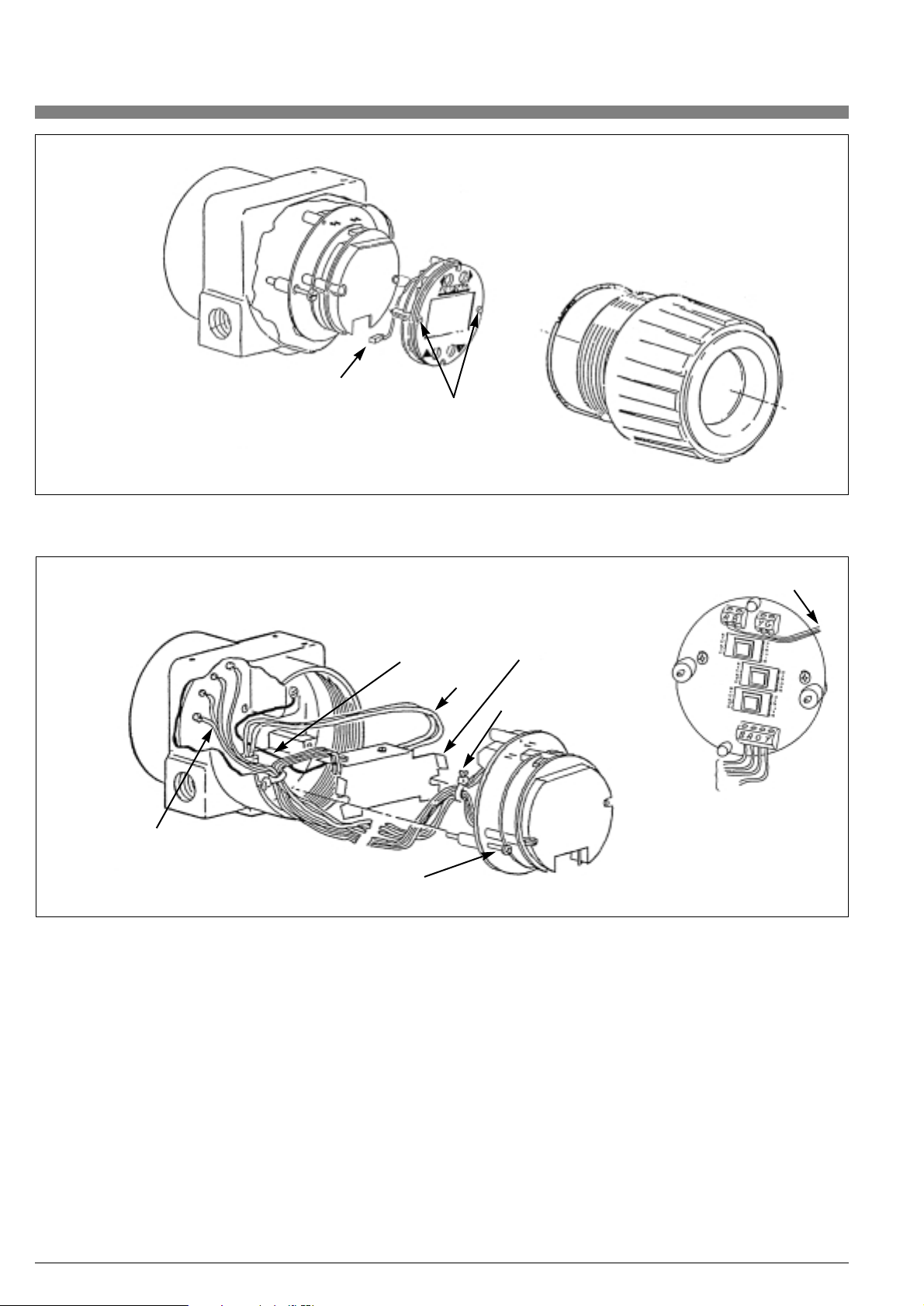
32
Ribbon cable
connector
Display mounting
screws
Ground wire
Sensor wires
Retaining tabs
Tie wrap
Captive screw
Preamplifier
wires
Output signal wires
Signal wires
Figure 19. Electronic Module with Display Connections
Figure 20. Electronic Module Connections - CENELEC Certified
Extended and Standard Temperature Range.
Note: Do not cut the plastic tie wraps.
CENELEC Certified VFM 3100 Electronic Module Removal
The electronics of the CENELEC certified flameproof version
are similar to the Extended Temperature Range VFM 3100.
The CENELEC version has a housing with locking covers on
both the electronic module and field terminal sides.
• Remove power from the VFM 3100.
• Take off the cover lock assemblies by removing the two M6
socket cap screws with a 5 mm hexagonal wrench.
Save these lock assemblies.
• Once the lock assemblies are off, remove the electronic module
cover. Unscrew the two captive screws (one on each side of the
electronic module). See Figure 20.
• Pull the electronic module far enough out of the housing to
disconnect the preamplifier leads (brown-red-orange-yellow
cable) from terminal block on the electronic module and to
disconnect the signal lead (red-blue, yellow-green cables) from
the terminal blocks. Do not disconnect ground wire from housing.
• Remove electronic module from housing.
NOTE: Do not cut the plastic tie wraps.
Page 33
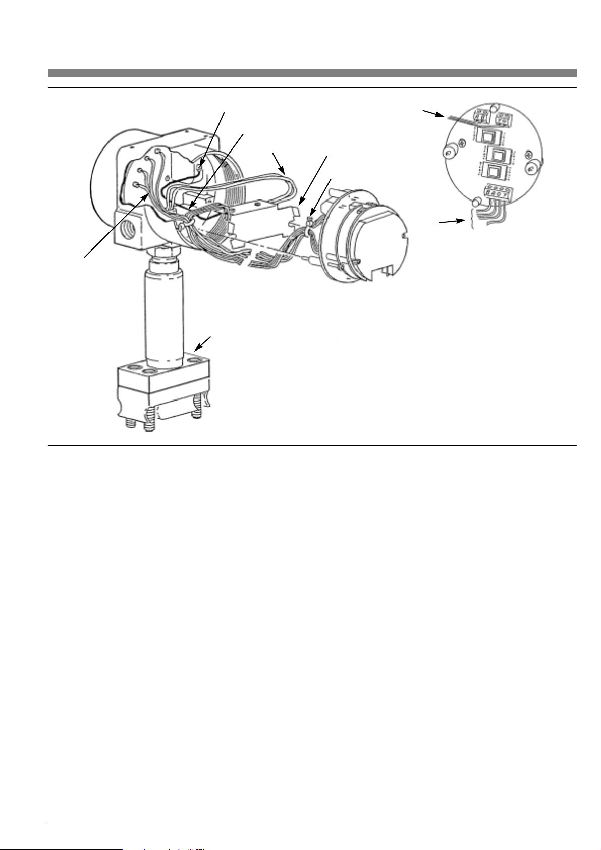
33
Ground screw with lockwasher
Ground wire
Sensor wires
Signal
wires
Shroud plate
Retaining tabs
Tie wrap
Output
signal
wires
Preamplifier
wires
Figure 21. Electronic Module - CENELEC
Certified Flameproof
4.3. Electronic Module Replacement
CAUTION: Ensure that power is not applied to the VFM 3100
before proceeding.
• Remove the electronic module following the appropriate
procedure starting on page 30.
NOTE: If a display is mounted to the electronic module, remove
the display, loosen the two mounting screws, and unplug the ribbon
cable from the electronic module. See Figure 19.
NOTE: The replacement electronic module is shipped in a protective
antistatic plastic bag. Do not remove it from this bag until it is ready
to be installed in a VFM 3100. This will minimize the possibility of
damage due to accidental electrostatic discharge. Use of an electrostatic mat will prevent electrostatic discharge.
• Remove the new electronic module from its protective bag.
The procedure for connecting the sensor and signal leads
see section below.
NOTE: The signal and sensor leads should already be held together
with a plastic tie.
Standard Temperature Range VFM 3100
• Refer to Figure 17. Connect the brown and yellow sensor
wires to the color coded terminal block on the back of the
electronic module.
Extended Temperature Range VFM 3100
(including CENELEC Flameproof)
• Refer to Figure 18. Connect brown-red-orange-yellow preamplifier cable to the color coded terminal block on back of the
electronic module. For CENELEC flameproof version, also
connect the ground wire from the preamp to the housing as
shown in Figure 21.
• Connect the signal leads (red-blue and yellow-green cables)
to the terminal blocks on the electronic module following the
color code on the label.
• After all the wires are connected, rotate the electronic module
one full turn clockwise before mounting. This will help prevent
the wires from being pinched. Locate the electronic module in
the housing over the two mounting holes. If a preamp is present,
be sure to align it also. Tighten the captive mounting screws.
• If the electronic module was equipped with a display, reassemble the display. Carefully fold the ribbon cable in the
space between display and the electronic module and tighten
the mounting screws.
• The new electronic module must be configured to match the
one just removed.
• Refer to the appropriate appendix for configuration.
• Perform post-assembly dielectric test. Refer to page 37.
When calibration is complete, replace the housing covers.
NOTE: For CENELEC only, attach lock assemblies on both sides
of the electronics housing prior to operating the VFM 3100.
Page 34

34
4.4. Preamplifier
The Preamplifier assembly (shown in Figure 22) consists of the preamplifier with a shield for integral mounted electronics (or with a mounting plate for remote mounted electronics, as shown in Figure 23).
The preamp has a sensor switch which must be set to STD for standard temperature sensors and set to EXT for extended temperature
range sensors.
4.4.1. Preamplifier Removal Integral Mounted VFM 3100
• Disconnect power from the VFM 3100.
• Remove electronic module compartment cover (opposite “Field
Terminal” side) and remove the electronic module as described
starting on page 30. Remove the brown, red, orange and yellow
preamplifier leads. Refer to Figure 18. It is not necessary to remove the display, if one is present.
• Cut the two tie wraps holding the preamplifier leads and signal
leads together.
• Pry the retaining tabs of the metal shield away from the housing,
using a straight blade screwdriver, and pull the whole assembly
out. See Figure 22.
• Turn the preamplifier upside down, disconnect the yellow and
brown sensor leads from the terminal block, and loosen the
strain relief clamp that holds the sensor cable.
• Pull the preamplifier out of the housing.
NOTE: For CENELEC certified flameproof VFM 3100, disconnect
preamplifier ground lead from housing. Save screw and lockwasher.
See Figure 21.
• Remove the Preamplifier from the shield by removing the two
screws. See figure 22. Save the two screws and metal shield.
• The replacement procedure starts on page 35.
Screws
Retaining tabs
Preamplifier
Metal shield
Figure 22. Preamplifer Assembly - Integral Mount Extended Temperature Range
Remote Mounted VFM 3100
See next section for remote mounted CENELEC version.
On remote mounted electronics, the Preamplifier is housed in the
junction box on top of the VFM 3100. The Electronic Module is in the
transmitter housing.
• Disconnect power to the VFM 3100.
• Remove the junction box cover. The Preamplifier and a 4-position two-sided terminal block are mounted on a round plate in
the junction box, as shown in Figure 23.
• Disconnect (brown-red-orange-yellow) wires from both sides
of the terminal block and remove strain clamp holding remote
cable.
• Disconnect yellow and brown sensor leads from terminals on
the preamplifier and loosen strain relief clamp holding the sensor
cable.
• Unscrew the two mounting screws to remove the mounting
plate from the junction box.
• Turn the mounting plate (with the preamplifier) upside down and
unscrew the two screws to remove the preamplifier. Save the
screws and the mounting plate assembly.
Remote Mounted CENELEC Certified Flameproof VFM 3100
• Remove power from the VFM 3100 . The transmitter and
junction box of a remote mounted CENELEC certified flameproof VFM 3100 have locks on their covers as shown in
Figure 24.
• To remove the Preamplifier, remove lock assembly of junction
box and remove cover. The Preamplifier with a metal shield over
it, a 4-position two-sided terminal block, and metal ground strap
are mounted on a round plate in the junction box.
Mounting
screw
Screws
Terminal
wire
Sensor wire
Mounting
screw
Preamplifier
wires
Figure 23: Preamplifier Assembly - Remote Mount Assembly.
Page 35

35
• Remove shield covering the Preamplifier and disconnect
the ground lead from U-shaped metal strap on the mounting
plate (Figure 24).
• Disconnect (brown-red-orange-yellow) wires from both sides of
the terminal block and remove strain relief clamp holding remote
cable. Refer to Figure 23.
• Disconnect yellow and brown sensor leads from terminal block
on the preamplifier and loosen strain relief clamp holding the
sensor cable.
• Unscrew the two mounting screws to remove mounting plate
from junction box.
• Turn the mounting plate (with preamplifier) upside down and
unscrew the two screws to remove preamplifier. Save the
screws, mounting plate assembly, cover lock assembly,
preamplifier shield with screws, and ground strap.
Ground wire
Cover look
assembly
Terminal block
Lockwasher
Mounting screw
Preamplifier assembly
Figure 24: Preamplifier - Remote Mounted VFM 3100
(CENELEC Certified Flameproof)
4.4.2. Replacing the Preamplifier
The replacement preamplifier is shipped in a protective anti-static
plastic bag with two tie wraps for dressing of wires. Do not remove
the preamplifier from this bag until it is ready to be installed in a
VFM 3100. This will prevent damage due to accidental electrostatic
discharge.
NOTE: An electrostatic mat will prevent electrostatic discharge
Remove the new preamplifier from its protective bag and follow the
installation procedure in “Integral Mounted VFM 3100” on page 36
and in “Remote Mounted VFM 3100” on page 36.
CAUTION: Before proceeding, make sure that power to
VFM 3100 is OFF.
Page 36

36
Sensor switch
Sensor
switch
Ground wire
Sensor wires
EXT
STD
Figure 25. Preamplifier Assembly
Integral Mounted VFM 3100
• Mount the new preamplifier to the metal shield using the original
screws. See Figure 22.
• Feed the yellow and brown sensor wires through the strain relief
clamp on the bottom of the preamplifier board. Tighten the
clamp and connect the sensor leads to the terminal block.
The color coding is important. Check to see that this is correct.
See Figure 25.
• Set the sensor switch to “STD” for standard temperature sensors
and to “EXT” for extended range temperature sensors.
• Before placing the preamplifier into the housing, bend the retaining tabs of the metal shield outward slightly to ensure a snug
fit against the housing walls. See Figure 18. Align the mounting
slots with the screw holes for mounting the electronic module.
• Once the preamplifier is in place, connect its four wires
(brown-red-yellow-orange cable) to the color coded terminal
block on back of the electronic module.
• Connect the output signal leads (red-blue, and yellow-green
cables) to terminal blocks on the electronic module, following
the color code on the label.
• Prior to mounting the main electronic module in the housing,
bring all the cables from preamplifier and the housing neatly
together as shown in Figure 18.
• While pushing the slack in the cables away from the back of
the electronic module, tie the cables together at two places,
using plastic tie wraps.
• Locate the electronic module in the housing by aligning the
preamplifier shield with the mounting holes.
• Rotate the electronic module one full turn clockwise before
mounting. This will help prevent the wires from being pinched.
Locate the electronic module over the mounting holes, align the
preamplifier, and tighten the captive mounting screws.
• Perform Post-Assembly Dielectric Test. Refer to page 37.
Replace threaded housing cover.
Remote Mounted VFM 3100
• Mount the new preamplifier on the mounting plate using the
two screws. Refer to Figure 23.
• Feed the yellow and brown sensor wires through the strain relief
clamp on the preamplifier board. Tighten the clamp and connect
the sensor leads to the terminal block. The color coding is
important. Verify that it is correct. See Figure 25.
• Connect (brown-red-orange-yellow) cable from preamplifier to
one side of the two-sided terminal block on the mounting plate.
See Figure 23.
• Before placing assembly into the junction box, connect the four
(brown-red-orange-yellow) wires entering the junction box
through a conduit opening, to the other side of the terminal
block on the mounting plate (following the same sequence as
the cable from the preamplifier). See Figure 26.
• Place mounting plate with preamplifier in the junction box and
mount it using the two mounting screws.
• Perform Post-Assembly Dielectric Test. Refer to page 37.
Replace the threaded junction box cover.
Page 37

37
Apply 500 V ac
or 707 V dc
between
shorted
terminals and
ground for
1 minute
Case ground terminal (earth)
Terminal block
Figure 27. Connections for Post-Assembly Dielectric Test
Figure 26. Preamplifier – Remote Mounted VFM 3100
4.6. Sensor Replacement with Integral
Electronic Module
The VFM 3100 does not need to be removed from the pipeline for
Sensor replacement. The pipeline must, however, be shut down and
emptied before loosening the connector bolts.
4.6.1. Disassembly
• Disconnect power from the VFM 3100. If the VFM 3100 is wired
with rigid conduit, it may be necessary to remove the field terminal cover and disconnect input wiring and conduit connections.
• Remove electronic module compartment cover.
(For CENELEC Certified Flameproof Extended Range
VFM 3100, remove lock assembly prior to removing the
housing covers.)
NOTE: If cover cannot be removed by hand, it may be necessary
to insert a flat bar in tapered cover slot to remove.
• Remove the electronic module and preamplifier and disconnect
the sensor leads per the instructions starting on page 30 for
meters with integrally mounted electronics housings.
• Remove the mechanical connector bolts and lift off the electrical
housing, mechanical connector, and sensor as a unit.
See Figure 28.
• Slide the sensor out of the mechanical connector.
See Figure 30.
NOTE: The Standard Temperature Range VFM 3100 has a ptfe gasket and flow dam and a silicone rubber O-ring. The Extended Temperature Range VFM 3100 has a stainless steel gasket and flow dam
and a Graphoil O-ring.
4.5. Post-Assembly Dielectric Test
To ensure there are no faults to ground in any of the internal wiring,
apply 500 V ac or 707 V dc dielectric strength test for 1 minute between shorted input terminals (+), (-), (A), (B), and housing ground as
shown in Figure 27.
Sensor switch
Sensor wires
Remote cable
Preamplifier assembly
Brown (+)
Red
Orange
Yellow (-)
Remote Mounted VFM 3100
(CENELEC Certified Flameproof)
• Mount the new preamplifier on the mounting plate using the two
screws. Refer to Figure 23.
• Feed the yellow and brown sensor wires through the strain relief
clamp on the preamplifier board. Tighten the clamp and connect
the sensor leads to the terminal block. The color coding is
important. Check to see that this is correct. See Figure 25.
• Connect (brown-red-orange-yellow) cable from the preamplifier
to one side of the two-sided terminal block on the mounting
plate.
• Before placing assembly into the junction box, connect the four
(brown-red-orange-yellow) wires entering the junction box
through a conduit opening, to the other side of the terminal
block on the mounting plate (following the same sequence as
the ribbon cable from the preamplifier). See Figure 23.
• Place mounting plate with preamplifier in the junction box and
mount it using the two mounting screws.
• Connect ground wire from the preamplifier to the U-shaped
ground strap on the mounting plate.
• Mount metal shield over the preamplifier as shown in Figure 24.
• Replace the junction box cover and add the lock assembly.
Page 38

38
4.6.2. Replacing the Sensor
NOTE: Before beginning the assembly procedure, verify that you
have the correct kit of parts.
The sensor kits consist of:
1 Sensor Assembly
1 O-ring
1 Gasket
1 Flow Dam
2 Tie Wraps
Field terminal
cover
Conduit
connection
Mechanical
connector
bolts (4)
Electrical housing
Cover
Cover slot (both covers)
Mechanical connector
O-Ring
Sensor assembly
Flow dam
Gasket
Body
Figure 28. VFM 3100 Assembly
The following steps apply to both Standard and Extended
Temperature Range VFM 3100:
• If the flow dam has remained in the VFM 3100 body, remove it
before starting to re-assemble.
• Slide O-ring over sensor lead and onto neck of sensor.
See Figure 29.
• Carefully feed sensor lead through hole in mechanical connector
and gently pull sensor lead out of electrical housing until sensor
is touching the mechanical connector. See Figure 31.
• Place the flat gasket over the sensor in contact with serrated
sealing surface. Center the gasket. Slide the flow dam into the
groove of the sensor.
• Insert the sensor with the connector into the VFM 3100 body
and assemble the four bolts finger tight.
Page 39

39
Figure 31: VFM 3100 Assembly
Sensor Assembly
O-Ring
Gasket
Flow dam
Cover
Cover O-Ring
Electronic Module
Captive mounting screws
Mechanical connector
Sensor assembly
Flow dam
Electrical housing
Sensor lead
Mechanical connector
Sensor assembly
O-Ring
Flow dam
Gasket
Access
hole
Body
Mechanical
connector
bolts (4)
Figure 29. O-Ring/Sensor/Flow Dam
Figure 30: Electrical Housing/ Mechanical Connector
WARNING: It is important that the gasket be sealed uniformly to
provide a good seal. The following steps will assure a uniform seal.
Failure to follow these steps could result in personal injury due to
gasket leakage.
• Tighten all connector bolts in steps of 1.2 Nm (1 lb•ft) up to
2.8 Nm (2 lb•ft) per the sequence shown in Figure 32.
For example,
means 1.2 Nm or 1 lb•ft.
1.2
1
Page 40

40
• Continue to tighten in steps of 7 Nm (5 lb•ft) using the same
sequence. The maximum torque needed for safe operation is
34 Nm (25 lb•ft) per Figure 33.
• Reassemble the Electronic Module and preamplifier per
instructions starting on page 33.
Attach conduit connections and input wiring. See “Field
Termination” on page 19 and “Interconnection Wiring for
Remote Electronics” on page 13.
NOTE: Replacing the sensor will not cause a shift in the K-factor.
WARNING: In order to maintain agency certification of this product
and to prove the integrity of the parts and workmanship in containing
process pressure, a hydrostatic pressure test must be performed.
The VFM 3100 must hold for 1 minute without leaking the appropriate pressure from Table 11.
Model End Connection Test Pressure
VFM 3100 F - T ANSI Class 150 450 psi
PN 16 3,2 MPa
VFM 3100 F - T ANSI Class 300 1125 psi
PN 40 6 MPa
VFM 3100 F -T PN 64 9,6 MPa
VFM 3100 F -T ANSI Class 600 2250 psi
PN 100 15 MPa
VFM 3100 W-T All 15 MPa (2250 psi)
Figure 32: Connector Bolt Torquing Sequence
Figure 33: Connector Bolt Torquing Sequence
Table 11. Maximum Test Pressure
maximum torque 34 Nm
(25 lb•ft)
Page 41

41
4.7. Sensor Replacement with Remote
Electronic Module
4.7.1. Disassembly
• Remove junction box cover (for CENELEC Certified Flameproof
VFM 3100, remove lock assembly and cover). See Figure 24.
a. Standard Temperature Range Sensor: Loosen strain relief
clamp. Disconnect yellow and brown sensor leads from
terminal block. See Figure 34.
b. Extended Temperature Range Sensor: Disconnect brown
and yellow sensor lead from terminal block on preamplifier.
See Figure 35. (For CENELEC Certified Flameproof
VFM 3100, remove preamplifier shield and then disconnect
the sensor leads from preamplifier.)
Remote cable
Brown (+)
Red
Orange
Yellow (-)
Ground (earth) screw
(cenelec flameproof only)
Sensor wires
Sensor switch
Preamplifier assembly
• Do not disconnect the interconnecting wiring to the remote
Electronic Module assembly.
• See Figure 36. Remove mechanical connector bolts.
(CENELEC Certified Flameproof VFM 3100 have special
connector bolts as well as a shroud plate over the standard
connector. Once the bolts are removed, the shroud plate is
retained between the connector and housing.)
• Lift the junction box mechanical connector and sensor as a unit.
• Slide the sensor and out of the mechanical connector as shown
in Figure 37.
Figure 34: Flowtube/Junction Box - Standard Temperature Range
Figure 35: Flowtube/ Junction Box - Extended Temperature Range
Remote cable
Brown (+)
Red
Orange
Yellow (-)
Ground (earth) screw
(cenelec flameproof only)
Sensor wires
Sensor switch
Preamplifier assembly
Page 42
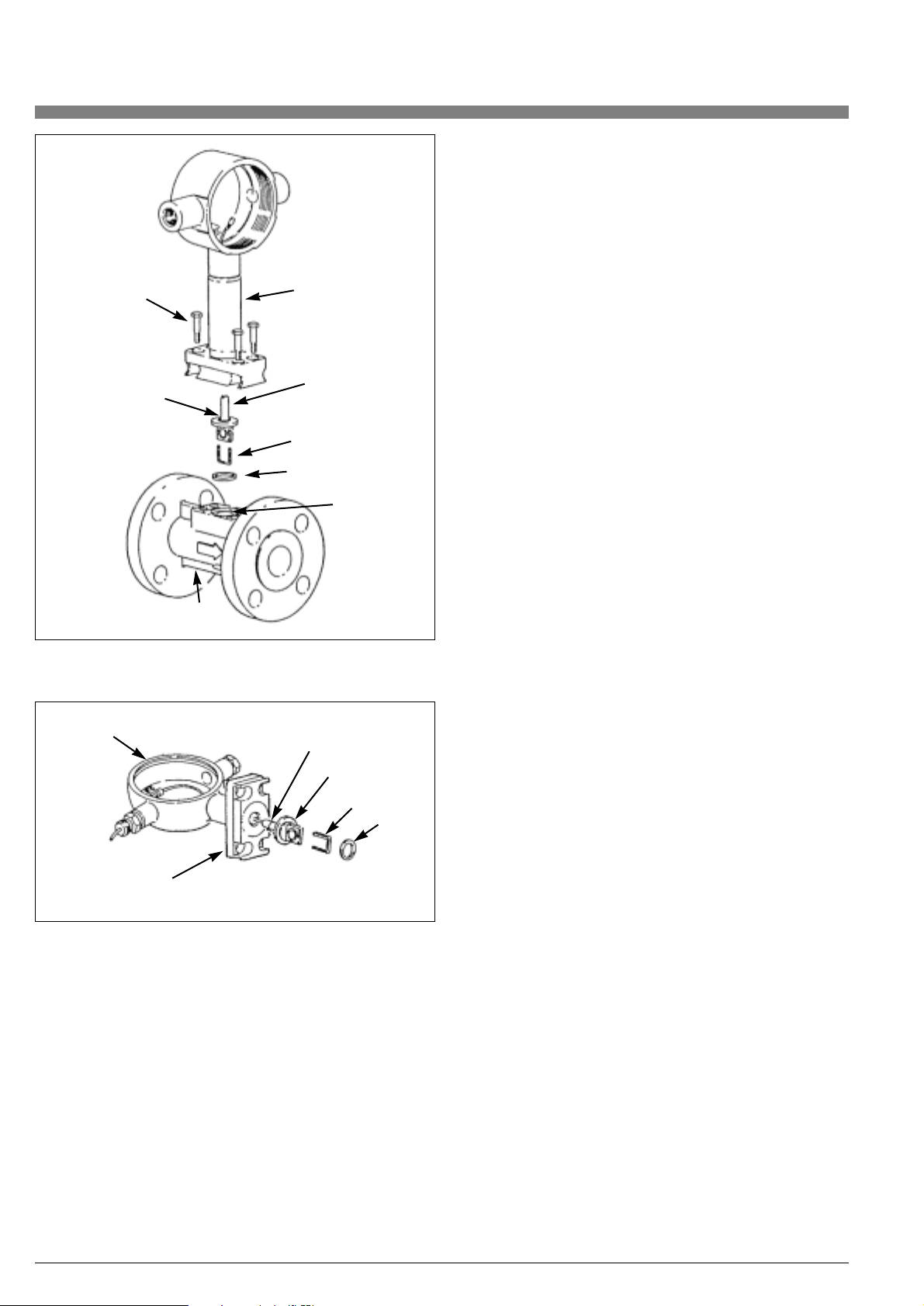
4.7.2. Assembly
NOTE: Before beginning the assembly procedure, verify that you have the correct kit of parts.
The sensor kits consist of:
1 Sensor Assembly
1 O-ring
1 Gasket
1 Flow Dam
Slide O-ring over sensor lead and onto neck of sensor.
See Figure 29.
The following steps apply to both Standard and Extended Temperature Range VFM 3100:
• If the flow dam has remained in the VFM 3100 body, remove it
before starting to reassemble.
• Carefully feed sensor lead through hole in mechanical connector
and gently pull sensor lead out of junction box until sensor is
touching the mechanical connector. See Figure 37.
CAUTION: For CENELEC certified flameproof units, take special
care not to scar, mar, ding, or dent the surface of the sensor stem
during assembly. This is critical to the integrity of the flameproof surface finish.
• Place the flat gasket over the sensor in contact with the serrated
sealing surface. Center the gasket. Slide the flow dam into the
groove on the sensor.
• Insert the sensor with the connector into the VFM 3100 body
and assemble the four bolts finger tight.
WARNING: It is important that the gasket be sealed uniformly to
provide a good seal. The following steps will assure a uniform seal.
Failure to follow these steps could result in personal injury due to
gasket leakage.
• Tighten all connector bolts to 3.4 Nm (25 lb•ft) per the
procedure starting on page 40. Refer to Figures 32 and 33.
• Attach conduit connections and input wiring. See “Field
Termination” on page 19.
NOTE: Replacing the sensor will not cause a shift in the K-factor.
Therefore, the VFM 3100 does not require recalibration.
• Connect the sensor wires to the color coded terminals as shown
in Figure 34 for the Standard Temperature Range sensor and in
Figure 35 for the Extended Temperature Range sensor.
WARNING: In order to maintain agency certification of this product
and prove integrity of the parts and workmanship in containing process pressure, a hydrostatic pressure test must be performed. The
VFM 3100 must hold for 1 minute without leaking the appropriate
pressure from Table 11, “Maximum Test Pressure,” on page 40.
42
Mechanical
connector
bolts (4)
Mechanical
connector
Sensor
assembly
Flow dam
Gasket
Sensor
assembly
O-Ring
Flow dam
Gasket
Access hole
Body
O-Ring
Junction box
Mechanical connector
Figure 36. VFM 3100 Assembly/Junction Box
Figure 37. Sensor/Mechanical Connector/Junction Box
Page 43

43
5. Determining Special Measuring Units
There may be a need to use flow units that are not listed in the units
menu. To enter custom units, select “special” from the flow and/or
total units menu.
The following four entries are required to configure the transmitter for
special flow and total units.
• Total name, maximum six characters,
is required for displaying total.
• Flow name, maximum six characters,
is required for displaying the flow rate.
• Total conversion factor for computing total.
• Flow conversion factor for computing flow.
The conversion factors must be related to the internal software and
the manner in which the VFM 3100 computes flow. The conversion
factor for total is a direct conversion from ft3to the desired units. The
conversion factor for flow is a direct conversion from ft3/sec to the
desired flow units. Any table of conversion factors may be used.
Example: Barrels per hour
To measure total in barrels and flow in barrels per hour.
Total Name: bbl
Flow Name: bbl/h
Total Conversion Factor: 0.1781 bbl/ft
3
Flow Conversion Factor: 0.1781 x 3600 = 641.2 bbl/h
where: 3600 = sec/hr
Example: BTU per minute
The conversion factor for total must be in BTU/ft3. If the BTU factor is
known in mass units, then it must be converted to volume units by
multiplying by density. The flow factor is a direct conversion from
ft3/sec to the desired units.
Total Name: BTU
Flow Name: BTU/m
Total Conversion Factor: (BTU/lb) x density
Flow Conversion Factor: (BTU/lb) x density x 60
where: 60 = sec/min
Example: Calories per hour
The conversion factor for total must be in calories/ft3. If the calories
factor is known in cal/kg, it must be converted to cal/ft
3
by multiplying
by the density and volume conversion factors (m
3
to ft3). The flow fac-
tor must be related to ft3/sec.
Total Name: cal
Flow Name: cal/h
Total Conversion Factor: (cal/kg) x density x 0.028317
where: 0.028317 = m3/ft
3
Flow Conversion Factor: (cal/kg) x density x 0.028317 x 3600
6. Isolation Valves
Isolation valving is available in single and dual measurement versions
for standard and extended range sensors. The following procedure
applies to all versions. Replacing the sensor in this type of unit is
essentially the same as replacing a sensor in units without isolation
valving. However, particular care must be taken since the process
does not need to be shut down.
WARNING: The isolation valve must be in the closed position prior
to replacing the sensor. It must be gradually depressurized so that
process fluid does not leak. Personal injury could result from such a
leak. Follow normal lockout procedures. Remove power from the
VFM 3100.
6.1. Replacing the Sensor
• Close the valve. This is a dual port, single ball 1/4-turn valve.
Use a wrench on the flat on the valve stem to turn clockwise
one quarter turn. See Figure 38.
NOTE: The right angle position indicator attached to the stem is not
a valve handle. Use a wrench on the valve stem flats.
• Allow the unit to cool down as required.
• Remove power from the VFM 3100 and disconnect input wiring
and conduit connections.
• Gradually loosen the four top bolts that connect the mechanical
connector to top surface of the valve body. Do not loosen the
bottom bolts.
• Allow trapped process fluid within valve body to depressurize.
• Remove the four connector bolts and lift off electrical housing,
mechanical connector, and Sensor as a unit.
NOTE: If electronic housing cover cannot be removed by hand, it
may be necessary to insert a flat bar in slot to remove.
• Proceed to remove the electronic module per instructions
starting on page 30 and replace the sensor per instructions
starting on page 38. Be sure the O-ring is installed on the
sensor and use a new flow dam and gasket.
• When the new sensor has been installed, mount the sensor and
mechanical connector to the valve body and tighten the bolts
per instructions starting on page 38.
• Since it is not possible to leak test the valve-to-connector joint,
it must be assembled carefully.
• Open the valve counterclockwise. Use care and check for leaks.
• Reinstall the electronic module and, when required, the preamplifier, using instructions starting on page 35.
• Reconnect the conduit and external wiring.
Refer to instructions starting on page 13.
• Replace the covers and resume operation. There should be no
need to recalibrate the electronic module.
Page 44

6.2. Replacing or Installing an Isolation Valve
The VFM 3100 does not need to be removed from the pipeline to
replace the isolation valve. However, the pipeline must be shut down
and emptied before loosening the mounting bolts.
• If the VFM 3100 is wired with rigid conduit, it may be necessary
to disconnect the input wiring and conduit connections.
• Remove the bolts holding the connector and the valve body.
• Remove and discard old gasket and flow dam. Install a new
gasket and flow dam on the lower section of the valve body and
assemble the valve into the VFM 3100 body. Refer to Figure 38
or Figure 39. These are the same gaskets and flow dams used
with sensors. For standard range valves, use gasket L0121DT
and flow dam L0112KT. For extended range valves, use gasket
K0146HL and flow dam K0146HK.
• Install the four bolts on the bottom flange and tighten, using the
procedure starting on page 38.
• Install a new gasket and flow dam on the sensor. Hold the
sensor, mechanical connector, and housing together and
carefully slide the sensor into the top of the valve body.
• Install the four bolts on the top flange and tighten, using the
procedure starting on page 38.
NOTE: The gasket must be uniformly sealed and the bolts properly
tightened on both the mechanical connector and valve body to assure a leak-tight seal. Failure to follow these steps could result in personal injury due to gasket leakage.
• Reconnect the conduit and external wiring. Refer to instruction
starting on page 13.
• Replace the covers and resume operation.
44
Mechanical
connector
O-Ring
Sensor
Gasket
Flow dam
Isolation valve
Wrench flat
Open
Close
Gasket
Flow dam
Figure 38. Isolation Valve
Page 45

45
7. HART Configuration Instructions
7.1. Introduction
Generic instructions regarding the installation and operation of the
HART Communicator can be found in the HART Communicator
Product Manual.
7.2. HART Menu Structure
The on-line menu structure for the HART Communicator is shown in
Figure 40. Key sequences for rapidly accessing given functions or
parameters are shown in Figure 41.
Mechanical
connector
O-Ring
Sensor
Flow dam
Gasket
Dual valve
Flow dam
Gasket
Figure 39. Dual Manifold
Page 46

46
1 DEVICE SETUP
2 FLOW RATE
3 ANALOG OUT
4 URV
5 LOW FLOW CUT IN
1 PROCESS VARIABLES
2 DIAG/SERVICE
3 BASIC SETUP
4 DETAILED SETUP
5 REVIEW
1 FLOW RATE
2 % RANGE
3 ANALOG OUT
4 VORTEX FREQ
5 PULSE OUT
FREQ
6 TOTAL
1 TEST DEVICE
2 LOOP TEST
3 CALIBRATION
1URV
2 USL
3 MIN SPAN
4 LOW FLOW
CUT IN
1 FLOW UNITS
2 TAG
3 RANGE
VALUES
4 DEVICE INFO
1 MEASURING
ELEMENTS
2 SIGNAL
CONDITIONING
3 OUTPUT
CONDITIONING
4 DEVICE INFO
UPPER RANGE VALUE (URV)
UPPER SENSOR LIMIT (USL)
MINIMUM SPAN
DAMPING VALUE
LOW FLOW CUT IN
MODEL CODE
METER BODY SERIAL NO.
REFERENCE K-FACTOR
PULSE OUTPUT MODE
FLOW UNITS
SPECIAL FLOW UNITS
CONVERSION FACTOR
SPECIAL FLOW UNITS
TOTAL UNITS
SPECIAL TOTAL UNITS
CONVERSION FACTOR
SPECIAL TOTAL UNITS
NOISE REJECTION
SIGNAL CONDITIONING
LOW FLOW CORRECTION
PROCESS TEMPERATURE
PROCESS DENSITY
BASE DENSITY
PROCESS VISCOSITY
MATING PIPE
PIPING CONFIGURATION
UPSTREAM DISTANCE
CUSTOM K BIAS
AO/PO ALARM TYPE
MANUFACTURER
DEVICE ID
TAG
DESCRIPTOR
MESSAGE
DATE
FLUID TYPE
UNIVERSAL REVISION
FIELD DEVICE REVISION
SOFTWARE REVISION
SOFTWARE RELEASE
HARDWARE REVISION
POLL ADDRESS
NO. OF REQUEST
PREAMBLES
1 PROCESS
VARIABLES
2 METER CONFIG.
3 FLOW UNITS CONFIG
4 PROCESS PARAM.
5 PIPING
6 CALIBRATION
7 TEST DEVICE
1 PROCESS VARIABLES
2 RANGE VALUES
3 FLOW UNITS CONFIG
4 CALIBRATION
5 SIGNAL PROCESSING
1 MFR
2 TAG
3 DESCRIPTIOR
4 MESSAGE
5DATE
6 DEVICE
DESCRIPTION
7 REVISIONS
1 SELF TEST
2 STATUS
1 SET DIGITAL OUT
2 SET ANALOG OUT
3 SET PULSE OUT
1 D/A TRIM
2 SCALED
D/A TRIM
3 DATE
1 MFR.
2 TAG
3 DESCRIPTION
4 MESSAGE
5 DATE
6 DEVICE
DESCRIPTION
7 REVISIONS
F
G
H
E
D
C
B
A
4
5
6
7
8
9
3
2
1
Figure 40. HART On-Line Menu Structure – Part 1 of 2
Page 47
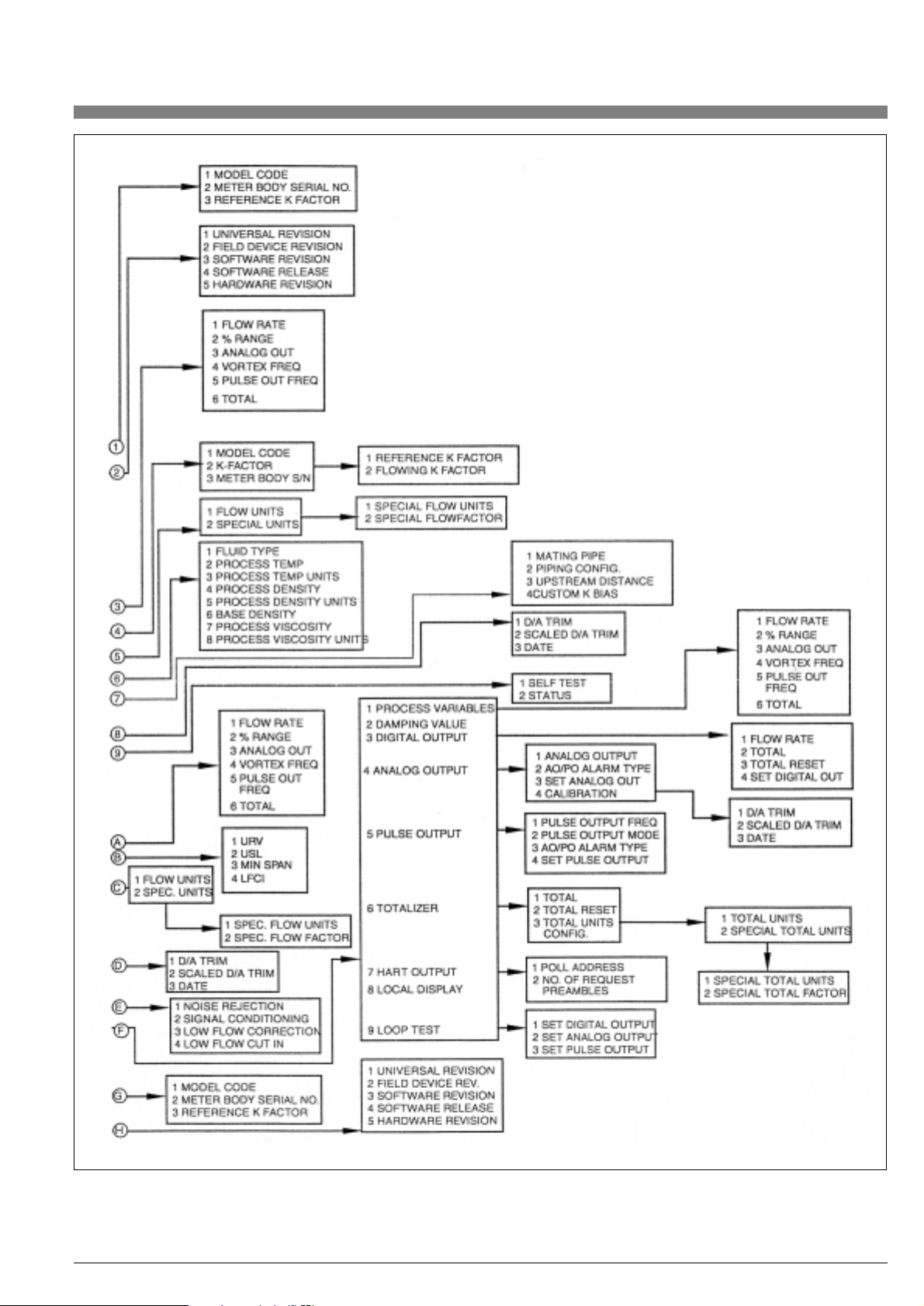
47
Figure 40. HART On-Line Menu Structure – Part 2 of 2
Page 48
48
Figure 41. Fast-Key Function/Varible Chart
FUNCTION/VARIABLE KEY SEQUENCE
Analog Output 3
AO/PO Alarm Type 1, 4, 3, 4, 2
Auto Low Flow Cut-In 1,3,3,4
D/A Trim 1,2,3,1
Damping Value 1,4,3,2
Date 1,2, 3, 2
Density, Base 1,4,1,4,6
Density, Process 1,4,1,4,4
Descriptor 1,3,4,3
Fluid Type 1,4,1,4,1
Flow Rate 2
Flow Rate (% of range) 1,1,2
K-Factor, Reference 1,3,4,6,3
K-Factor, Flowing 1,4,1,2,2,2
K-Factor Bias, Custom 1,4,1,5,4
Local Display 1,4,3,8
Loop Test 1,2,2
Low Flow Correction 1,4,2,5,3
Low Flow Cut-In 1, 3, 3, 4
Manufacturer 1,3,4,1
Message 1,3,4,4
Meter Body Serial Number 1,3,4,6,2
Minimum Span 1,3,3,3
Model Code 1,3,4,6,1
Noise Rejection 1,4,2,5,1
Number of Req. Preambles 1,4,3,7,2
Piping 1,4,1,5
Poll Address 1,4,3,7,1
Process Parameters 1,4,1,4
Process Variables 1,1
Pulse Output Frequency 1,1,5
Pulse Output Mode 1,4,3,5,2
Ranges Values 1,3,3
Review 1,5
Revisions 1,3,4,7
Scaled D/A Trim 1,2,3,2
Self Test 1,2,1,1
Signal Conditioning 1,4,2,5,2
Special Units, Flow 1,4,1,3,2
Special Units, Total 1,4,3,6,3, 2
Status 1,2,1,2
Tag 1,3,2
Temperature, Process 1,4,1,4,2
Total 1,1,6
Total Reset 1,4,3,6,2
Units, Flow 1,3,1
Units, Total 1,4,3,6,3,1
Upper Range Value (URV) 1, 3, 3, 1
Upper Sensor Limit (USL) 1,3,3,2
Vicosity, Process 1,4,1,4,7
Vortex Frequency 1,1,4
Page 49

8.2.3. Moving inside the Menu System
Pressing ESC will stop displaying measurements, and show the first
menu item, DISPLAY. From here, the four buttons allow the user to
move around the menu tree, as indicated by the arrows. Press the
down arrow repeatedly; the menu display will cycle through each of
the top level (Level 1) menu items. Refer to the menu structure diagram on the following pages as you move around
NOTE: Each menu item has its level (1 - 4) displayed at the beginning
of the top line.
The four buttons also allow the user to move up and down the picklists, as indicated by the arrows. Also, pressing ESC moves one from
the current level to the next higher level. Pressing ESC within the top
level menu returns the user to the MEASURE block.
8. Local Configuration Instructions VFM 3100
8.1. Introduction
Local configuration of the VFM 3100 is accomplished via four multifunction pushbuttons on the local keypad/display shown below.
A functional overview of the Menu Tree is presented in Table 12.
8.2. Using the Local Configurator
8.2.1. Measurements (MEASURE)
The system starts up displaying the measured Flowrate (FLOW), the
Total (TOTAL), or the Flow and Total (BOTH), in an alternating fashion,
depending on the selection made in the Calibrate/Show menu.
8.2.2. Display Bar Indicator
The analog bar indicator at the top of the display indicates the flow
measurement, as a percentage of the upper range value.
NOTE: If the flow measurement is out-of-range, the bar indicator will
blink. If the transmitter is off-line, the middle four bars of the bar indicator will blink.
In TEST/SET DIG, the bar indicator continues to display the flow
measurement. However, in TEST/SET MA, it displays the percentage of span set.
49
Level 1 Level 2 Function
MEASURE Display Flowrate and Total
DISPLAY OPTIONS Display Transmitter and Output Options
PARAMS Display Fluid and Application Parameters
TAGS Display Flowtube and ID Parameters
CALIB SHOW Set Measurement Display Mode
LFCI Set Low Flow Cut-In
RESET TOTAL Set Total to Zero
CAL 4 mA mA Calibration @ 4 mA
CAL 20 mA mA calibration @ 20 mA
TEST DIAG Display Status
SET DIG Set Digital Output for Loop Calibration
SET MA Set 4-20 mA Output for Loop Calibration
SET HZ Set Scaled Pulse Output for Loop Calibration
SELFTST Activate Transmitter Self-Test
XMTTEMP Display Transmitter Temperature
CONFIG OPTIONS Select Transmitter Options
OUTPUT Select Output Option
FLUID Enter Fluid Parameters
UNITS Enter Units, URV, and Damping
BIAS Enter Application Parameter
TAGS Enter Identification Parameters
NEWTUBE Enter Flowtube Parameters
PASSWD Change Passwords
Table 12. Menu Tree Functional Overview
Page 50

50
The right arrow moves the cursor to the right; ENTER accepts the
change at the end. The left arrow moves the cursor to the left; ESC
cancels the change at the beginning.
There are three kinds of edit items: signed numbers, unsigned numbers, and strings.
Unsigned numbers cycle through the digits 0-9, and the decimal
point, with the up and down arrows. For example try changing the
CONFIG/FLUID/DENSITY item to 8.200.
When you enter a decimal point in any position, and there is already
a decimal point to the left of the cursor, the new decimal point overrides the old one. Change the DENSITY from 8.200 to 82.00 by first
selecting the decimal point to the right of the 2. Notice what happens
when you enter the second decimal point (i.e., press the Right arrow).
Signed numbers always have a + or - sign at the beginning.
The + can only be changed to –, and vice versa.
Finally, characters in strings may be changed to any valid character.
The sequence of characters you can get for strings by pressing the
up and down arrows is: space, A-Z, a-z, 0-9, period, dash, slash. Go
to CONFIG/TAGS/GEOLOC and change it. Note that the entire data
field is not visible at once. To enter the change you must still press
ENTER from the right side of the data field, after scrolling to the right
side with the right arrow.
8.2.9. Picking from a List
Pick-List items allow the user to choose a value from a transmitter
supplied list of alternatives. Go to CONFIG/FLOW/UNITS, and press
ENTER. The entire bottom line of the display flashes. If you press the
up or down arrows, the display will show the next or previous choice
from its list. Pressing ENTER will accept the change; pressing ESC
will return the previous value.
8.2.10. mA Calibration (TEST/CAL 4 mA or CAL 20 mA)
When opening the CAL 4 mA or CAL 20 mA menu block, 0.5+/– will
be displayed. To enter this value, i.e., to change the mA output of the
transmitter, press the up arrow to add 0.5 mA, or down arrow to subtract 0.5 mA. By pressing the right arrow values of 0.05 and 0.005
can be selected, and entered by the up and down arrows. The display will not change when entering the selected value. To have the
new calibration accepted by the transmitter, move with the right
arrow to the end of the data field. To restore the original calibration,
move with the left arrow to the beginning.
8.2.11. Transmitter Status
If there is a transmitter failure, an error message will appear when
entering the TEST menu.
8.2.12. Changing the Password
Changing the password is done in CONFIG/PASSWD. Before changing the password, a prompt will appear requesting the old password to be entered. CALIB and TEST share the same password.
A different password can be used for CALIB.
8.2.4. Viewing Data (DISPLAY)
The OPTIONS, PARAMS, and TAGS sub menus are all read only.
You may move around in them, but not alter any data.
In the PARAMS menu, the display alternates for all menu items
between the parameter name and value/units (This is also the case
when viewing the Transmitter Temperature in TEST/XMTTEMP).
Go to PARAMS/URV; note that the “URV” and value/units alternate.
In the TAGS menu, the alphanumeric strings may be longer than the
number of displayed characters. To shift the hidden characters into
view, press the right or left arrow buttons. Go to TAGS/MODEL, and
press the right arrow key several times. The MODEL string will scroll
to the left, allowing you to view the hidden characters. To exit this
menu item, either press the up or down arrows, or press ESC repeatedly until the string scrolls back to its original position.
8.2.5. Answering a Question
There are several places in the menu tree where a question will be
displayed, such as “LOOP IN MANUAL?”, mentioned below in
“Entering the Password.” To answer ‘Yes’, press ENTER, if ‘No’,
press ESC.
8.2.6. Entering the Password
The CALIB, TEST and CONFIG sub menus require a password
(a 4-character alphanumeric string). Changing the password will be
addressed later. Select the CALIB, TEST or CONFIG menu from
the top level, and press Enter at the PASSWD prompt. Two brackets
surrounding 4 spaces ([____]) will appear on the second line of the
display. The cursor, a flashing icon, appears at the first character.
To enter the password, use the up and down arrows to scroll through
the list of acceptable characters. After selecting the desired
character, press the right arrow to move to the next character.
Continue this process until the password is complete. Pressing
the right arrow once more moves the flashing cursor to the right
bracket. Pressing Enter now completes the process. Prior to
pressing Enter, the left and right arrows can be used to move back
and forth to modify an incorrect selection.
If you enter an incorrect password, the display will indicate “SORRY”
for 1 second, then return to the PASSWD prompt.
After entering the correct password, the following message will appear, “LOOP IN MANUAL?”. Press ENTER if ‘Yes’, ESC if ‘No’. ‘Yes’
moves the user into the calibration, test, or configuration submenus. ‘No’ returns you to CALIB or CONFIG in the main menu.
The default password from the factory for TEST, CALIB, and CONFIG is [____], (four spaces). To enter it quickly, press the right arrow 5
times.
8.2.7. Activating an Edit, Pick-List or User Function Menu
Block
To open a menu block that allows the user to edit or select data or to
perform a function, such as RESET TOTAL, move to the menu block
and press the Right arrow.
8.2.8. Editing Numbers and Strings
Editing any number or string in the menu system is done in the same
way as entering the password above. The up and down arrows scroll
through a list of acceptable characters for the current position.
Page 51

51
8.4. Local Configurator Menu (1 through 8)
MEASURE
DISPLAY OPTIONS
PULSE
OUT OFF
NOISE
FILT OFF
SIGNAL
COND OFF
BRANCH
BRANCH
PICK LIST
R/O
PICK LIST
R/O
PICK LIST
R/O
PICK LIST
R/O
LF CORR
OFF
1of8
OFF
ON
OFF
ON
RATE
OFF
OFF
ON
8.3. Local Configurator Menu Tree
8.3.1. Reading the Menu Tree
The menu tree used to carry out local configuration is shown on the
following pages. Each block on the menu diagram signifies a menu
item. The text in the block indicates the title of the item, and any data
displayed. The text under each block indicates the type of menu item.
There are five item types: Branch, Edit----, PickList, Group, and UserFunc.
• Branch items do not display or edit data, but simply move you to
another menu item depending on which key is pressed.
• Edit ---- items* display a numeric (real or integer) or string value,
which may be edited.
• PickList items* display one of several alternatives, which may
be selected. PickList items have the choices to pick from enclosed
in a dashed box to the right of the item.
• Group items display, alternately, a parameter name and its
value/units. You are not allowed to change them at this point in the
menu tree.
• UserFunc items do not display or edit data, rather they allow a
built-in function to be activated.
• * Edit---- and PickList items marked R/O (read only) will display
the associated data, but you will be unable to change them at this
point in the menu tree.
Figure 42.
Page 52

52
PARAMS
BRANCH
URV
LFCI
K REF
K FLOW
DAMPING
0 SEC
XXX.
F
XX.XX
P/USGAL
XXX.X
PUL/FT3
X.XXX
USGPM
XXX.X
USGPM
XX.XX
LB/FT3
X.XXX
CPOISE
FLTEMP
FLDENS
FLVISC
2of8
GROUP
GROUP
GROUP
GROUP
GROUP
GROUP
GROUP
EDIT REAL
R/O
Page 53

53
CALIB
TAGS
BRANCH
TAG
XXXX
DESCRIPT
XXXXXXXX
DATE
XXXXXXXX
MESSAGE
XXXXXX
POLLADR
XX
SER NO
XXXXXXXX
MODEL
XXXXXXXX
FIRMREV
XX.XX
PASSWD
XXXX
LOOP IN
MANUAL?
SHOW
FLOW
SHOW
1 = FLOW
2 = VORTEX FREQ
3 = PULSE OUT FREQ
4 = TOTAL
LFCI
AUTO
RESET
TOTAL
ARE YOU
SURE?
BRANCH BRANCH, STRINGCHK BRANCH
EDITSTRING
R/O
EDITSTRING
R/O
EDITSTRING
R/O
EDITSTRING
R/O
PICKLIST
R/O
EDITSTRING
R/O
EDITSTRING
R/O
USERFUNC
PICKLIST
PICKLIST
USERFUNC BRANCH
USERFUNC
USERFUNC
CAL4MA
X.XXX
CAL20MA
X.XXX
3 of 8
1---
-2-12-.
.
1234
XX.X
.
XX.X
AUTO
Page 54

54
TEST
PASSWD
XXXX
LOOP IN
MANUAL?
SET DIG
XX.X
SET MA
XX.X
SET HZ
XX.X
SELFTST
XMTTEMP
CONFIG
PASSWD
XXXX
FAIL
LOW
OUTPUT
PULSE
OUT OFF
LOOP IN
MANUAL?
OPTIONS
NOISE
FILT OFF
SIGNAL
COND OFF
LF CORR
OFF
SET DIG
XX.X
SET MA
XX.X
SET HZ
XX.X
TEST
PASSED
XXX.
C
OFF
ON
LOW
HIGH
RATE
OFF
BRANCH BRANCH, STRINGCHK BRANCH EDITREAL
ONLINE LOCAL
EDITREAL
EDITREAL
BRANCH
EDITREAL
R/O
EDITREAL
R/O
EDITREAL
R/O
USERFUNC
GROUP
BRANCH
BRANCH PICKLIST
PICKLIST
PICKLIST
PICKLIST
PICKLIST
BRANCH, STRINGCHK BRANCH
ONLINE CONFIGCNFPWD
BRANCH
4of8
OFF
ON
OFF
ON
Page 55

55
FLUID
TYPE
LIQUID
TEMP
F
TEMP
XXXX
DENSITY
LB/FT3
DENSITY
XXXX
BASEDEN
XXXX
VISCOS
CPOISE
VISCOS
XXXX
CHANGE
DEFAULT?
C
F
KG/M3
LB/FT3
CSTOKE
CPOISE
LIQUID
GAS
STEAM
PICKLIST
EDITREAL
PICKLIST
EDITREAL
EDITREAL
PICKLIST
EDITREAL
PICKLISTBRANCH
5of8
Page 56

6of8
56
UNITS
UNITS
FLOW TOTAL
cfm gal
USGpm l
l/min lmpGal
lmpGpm m3
m3/hr bbl
USG/s bushel
MilG/d yd3
l/sec ft3
Mill/d in3
ft3/s bbl
ft3/d nm3
m3/sec nl
m3/day scf
lmpG/h hl
lmpG/d g
nm3/hr kg
nl/hr mt
scfm lb
cfh sT
m3/min IT
bbl/s oz
bbl/m Special
bbl/h
bbl/d
USGph
ImpG/s
l/hr
USG/d
ft/s
m/s
m/hr
g/sec
g/min
g/hr
kg/s
kg/min
kg/hr
kg/day
mt/min
mt/hr
mt/day
lb/s
lb/min
lb/hr
lb/day
sT/min
sT/hr
sT/day
IT/hr
IT/day
Special
FLOW
(SEE LIST)
TOTAL
(SEE LIST)
URV
XXXX
DAMPING
XX.XX
TOTFAC
XX.XX
TOTNAME
XXXXXX
FLOWFAC
XX.XX
FLONAME
XXXXXX
BRANCH PICKLIST
PICKLIST
EDITSTRING
EDITREAL
EDITSTRING
EDITREAL
EDITREAL
EDITREAL
Page 57

7of8
57
BIAS
TAGS
PIPE
X.XX
BORE
SCHED 10
TAG
XXXXXXXX
DESCRIPT
XXXXXXXX
DATE
XXXXXXXX
MESSAGE
XXXXXXXX
POLLADR
XX
PIPING
X.XX
CONFIG
STRAIGHT
DIST
00.0
CUSTOM
XX.X
BRANCH BRANCH BRANCH
PICKLIST
EDITREAL
EDITREAL
PICKLIST
EDITSTRING
EDITSTRING
EDITSTRING
EDITSTRING
PICKLIST
BRANCH
PN100
PN64
PN40
PN16
SCHED 80
SCHED 40
SCHED 10
SANITARY
REDUCER
2L5PDPAR
2L5PDPER
2L0PDPER
2L0PDPAR
1 EL PER
1 EL PAR
STRAIGHT
Page 58

58
NEWTUBE
PASSWD
OLD
XXXX
CALIB
XXXX
ARE YOU
SURE?
CONFIG
XXXX
ARE YOU
SURE?
MODEL
XXXXXXXX
SER NO
XXXXXXXX
K-REF
XXXX
CONFIG
STANDARD
CALDATE
041201
INITIAL
XXX
STANDARD
MANIFOLD
DUAL
DUAL/ISO
BRANCH EDITSTRING
EDITINT
EDITREAL
PICKLIST
OLD MODEL CODE ONLY
USERFUNC
EDITSTRING
BRANCH BRANCH, STRINGCHK EDITSTRING USERFUNC
EDITSTRING USERFUNC
8of8
Page 59

59
9. Configuration Database
This appendix defines and describes the parameters in the configuration database shown in the following table.
In the following a number in braces {#} indicates the maximum string
length for alphanumeric parameters.
9.1. Flowtube Parameters
• Model Code (MSCode) [alphanumeric entry, {16}]
This is a manufacturer defined quantity. It resides on the VFM 3100
tag and in the database if the electronics and flowtube are shipped
as a unit.
Default: ‘blank’, if electronic module is shipped alone
• Meter Body Serial Number [alphanumeric entry, {16}]
This is a manufacturer defined quantity. It resides on the VFM 3100
tag and in the database, if the electronics and flowtube are shipped
as a unit.
Default: ‘blank’, if electronic module is shipped alone
• Reference K-Factor [numeric entry]
This is the reference calibration factor. It is entered as a pure number.
The value of the number is sufficient to define the proper units, i.e.,
pulses/ft3or pulses/liter. It resides on the VFM 3100 tag and in the
database, if the electronics and flowtube are shipped as a unit.
Default: ‘blank’ if electronic module is shipped alone
9.2. Identification Parameters
Ta g [alphanumeric entry, {8}]
This is a user defined quantity.
Default: ‘blank’
Descriptor [alphanumeric entry, {16}]
This is a user defined quantity.
Default: ‘blank’
Date [numeric entry, {6}]
This is a user defined quantity. In the case of the HART Configurator
the Date (XXXXXX) is expressed as MMDDYY, for the Local Configurator it is express as YYMMDD.
Default: HART = 051194, Local = 940511
Message [alphanumeric entry, {32}]
Default: ‘blank’
Polling Address [numeric entry, {2}]
This is a user defined quantity. The HART protocol allows the
connections of up to 15 HART devices on a single twisted pair of wires, or over leased telephone lines, a concept known as ‘multidropping’. In a multidrop installation, each transmitter is identified by a
unique address (1-15) referred to as the polling address. In the multidrop mode, i.e., a non-zero polling address, the analog output of the
transmitter is set to a fixed value of 4 mA. For a non-multidrop installation, i.e., a single transmitter loop, the polling address of the transmitter must be set to zero if the analog output is intended to indicate
flow (4-20 mA).
Default: 0
Flowtube Parameters
• Model Code
• Meter Body Serial Number
• Reference K-Factor
Identification Parameters
• Tag
• Descriptor
• Date
• Message
• Polling Address
Transmitter Options
• Flow Units
• Total Units
• Noise Rejection
• Signal Conditioning
• Low Flow Correction
• Low Flow Cut-In
Process Fluid Parameters
• Fluid Type
• Process Temperature
• Process Density
• Base Density
• Process Viscosity
Application Parameters
• Mating Pipe
• Piping Configuration
• Upstream Distance
• Custom K-factor Bias
• Upper Range Value
Output Options
• Damping Value
• Pulse Output
• AO/PO Alarm Type
Table 13. Configuration Database
Page 60

60
9.3. Transmitter Options
Flow Units [Pick-List]
This selection defines the units for the measured flow rate. Selecting
Special Units allows the user to define units not listed. The procedure
for doing this is described in chapter 5.
Default: USgpm
Total Units [Pick-List]
This selection defines the units for the measured total rate. Selecting
Special Units allows you to define units not listed. The procedure for
doing this is described in chapter 5.
Default: USgal
Noise Rejection [On,Off]
This selection allows the user to turn off the adaptive noise rejection
feature. When On, this feature improves VFM 3100 performance by
rejecting process noise. Off would normally be selected only for
troubleshooting the process.
Default: On
Signal Conditioning [On,Off]
This selection provides the user a means of turning off the low flow
signal conditioning feature. When On, this feature improves VFM
3100 performance by reducing the adverse effects of process noise
on the vortex signal. Off would normally be selected only for troubleshooting the process.
Low Flow Correction [On,Off]
This selection provides a means for turning on the low flow K-factor
correction. When On, this feature corrects for the nonlinearity of the
K-Factor that occurs at Reynolds Numbers below 20,000. The default for this parameter is Off to alert the user to the fact that actual
values of the Process Density and Viscosity must be entered into the
database to achieve improved accuracy.
Default: Off
Low Flow Cut-In [Pick-List]
The low flow cut-in parameter allows the user to set the level above
which the VFM 3100 begins to measure flow, i.e., the lower range limit of the VFM 3100. This process can be carried out automatically if
the flow is turned off. Otherwise, manual selection from the following
pick-list of eight levels can be made:
AUTO, (L0), (L1), (L2), (L3), (L4), (L5), (L6), (L7)
For convenience, these levels are displayed as estimated flow rates
in the selected flow units. The value of these flow rates depend on
the specific application parameters.
Default: (L3)
9.4. Process Fluid Parameters
Fluid Type [Pick-List: Liquid, Gas, Steam]
Three options are available: Liquid, Gas, or Steam. Knowledge of the
process fluid type is necessary for the automatic selection of default
process fluid properties.
NOTE: If a standard volume output is desired, the user is required to
enter base density.
Default: Liquid
Process Temperature [numeric entry for value;
Pick-List for units: °F,°C]
This is the actual temperature at process conditions. It is needed to
make the thermal expansion correction to the K-Factor.
Default: 70 °F or 20 °C (depending on units of Reference K-Factor)
Process Density [numeric entry for value;
Pick-List for units: LB/FT3,KG/M3]
This is the actual density at process conditions. It is needed by the
VFM 3100 to compute internally the lower and upper flow range limits. It is also needed to compute mass flow, if selected.
NOTE: Enter density, not specific gravity.
Default depends on selected fluid type and units of
Reference K-Factor:
• Liquid - 62.301 LB/FT3; 998.2 KG/M3
• Gas - 0.5858 LB/FT3; 9.546 KG/M3
• Steam - 0.2992 LB/FT3; 4.618 KG/M3
Base Density [numeric entry]
This information is only applicable if output in standard volume is desired. Units are the same as those selected for the flowing density.
Default depends on selected fluid type and units of Reference
K-Factor:
• Liquid - 62.374 LB/FT3; 999.2 KG/M3
• Gas - 0.07634 LB/FT3; 1.293 KG/M3
•Steam - 0.03730 LB/FT3; 0.5977 KG/M3
Process Viscosity [numeric entry of value; Pick-List for units:
Absolute (CPOISE), Kinematic (CSTOKE)]
This is the actual viscosity at process conditions. It is required only if
the Low Flow Correction is On.
Default depends on selected fluid type and units of
Reference K-Factor:
• Liquid - 0.9753 CPOISE or 1.002 CPOISE
• Gas - 0.0186 CPOISE or 0.0185 CPOISE
• Steam - 0.0150 CPOISE or 0.0149 CPOISE
9.5. Application Parameters
Mating Pipe [Pipe Schedule Pick-List]
This menu selection allows the Reference K-factor to be corrected
internally for piping bore mismatch upstream of the VFM 3100. The
pick-list is as follows:
SCHED 10, SCHED 40, SCHED 80
PN 16, PN40, PN 64, PN 100
SANITARY
Default: SCHED 40 (corresponds to zero bias)
Page 61
61
Straight
1 L paral to shed
1 L perp to shed
2 L cls paral shed
2 L cls perp shed
2 L 5 dia paral
2 L 5 dia perp
Reducer
Configurator
HART
Local
Piping
Descripton
STRAIGHT
1 EL PAR
1 EL PER
2L0PDPAR
2L0PDPER
2L5PDPAR
2L5PDPER
REDUCER
50 PD or more of straight pipe up-stream of VFM 3100
Single, long radius, 90˚ elbow; vortex shedder parallel to plane of elbow
Single, long radius, 90˚ elbow; vortex shedder perpendicular plane
of elbow
Two elbows in series and in different planes; vortex shedder parallel
to plane of closest elbow; elbows close coupled, i.e., no separation
Two elbows in series and in different planes; vortex shedder perpendicular to plane of closest elbow; elbows close coupled, i.e., no separation
Two elbows in series and in different planes; vortex shedder parallel
to plane of closest elbow; elbows have 5 pipe diameter separation
Two elbows in series and in different planes; vortex shedder perpendicular to plane of closest elbow; elbows have 5 pipe diameter separation
Reducer with either a 3:2 or 4:3 reduction
Default: STRAIGHT (corresponds to zero bias) and 30.0 PD
Custom K-Factor Bias [numeric entry in percent]
This allows entry of a user established bias in percent to correct
the Flowing K-Factor. This bias correction is in addition to those
addressed above, i.e., Mating Pipe and Piping Configuration/
Upstream Distance.
Default: 0.0
Upper Range Value [numeric entry]
This allows the user to set the upper range operating limit of the
VFM 3100. In the case of 4 to 20 mA output, it also establishes the
flow value corresponding to 20 mA; and in the case of scaled pulse
output, the flow value corresponding to 100 Hz.
Default: Upper Range Flow Limit
9.6. Output Options
Damping Value [numeric entry]
This feature allows the flow rate output to be smoothed.
Default: 2 seconds
Scaled Pulse Output [Pick-List: Off, Rate]
The Scaled Pulse Output, a contact closure, provides a frequency
output that is linearly related to the flowrate, the upper range value
being set to 100 Hz. For example, for a flow range to 0 to 500
USgpm, the frequency of the scaled pulse output goes from 0 to
100 Hz.
Default: Off
AO/PO Alarm Type [Pick-List: Lo, Hi]
This allows the user to pick the desired output that the instrument
will go to in the event of a transmitter failure:
Digital Not Applicable
4 to 20 mA Downscale (3.75 mA)
Upscale (20.38 mA)
Scaled Pulse Downscale (Off)
Upscale (125 Hz)
Default: Upscale
Piping Configuration [Pick-List]/
Upstream Distance [numeric entry]
These selections allow the Reference K-factor to be corrected automatically for upstream piping disturbances via a menu selection of
the piping configuration and a numeric input of the upstream pipe
length in pipe diameters (PD). The piping configuration pick-list is as
follows
 Loading...