

Page 1
Supplementary instructions
Supplementary instructions
VA40
VA40
VA40VA40
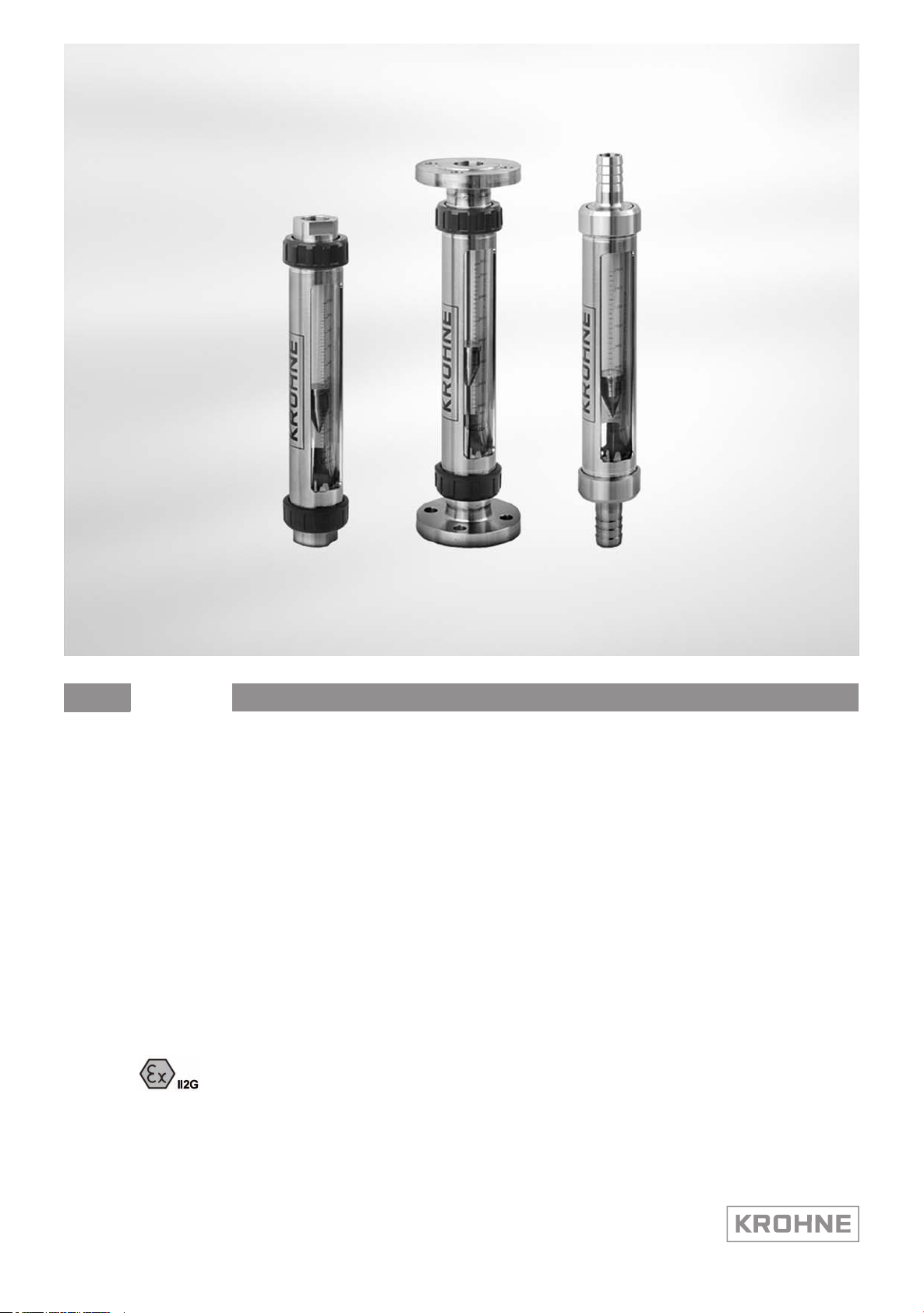
Variable area flowmeter
Equipment category II 2 G with electrical components
Supplementary instructions Supplementary instructions
© KROHNE 06/2013 - 4002262402 - MA VA40-Ex-II2G-AD R02 en
Page 2

CONTENTS
VA40
1 Safety instructions 3
1.1 General notes ................................................................................................................... 3
1.2 EC conformity ................................................................................................................... 3
1.3 Security information......................................................................................................... 3
2 Device description 4
2.1 Device description ............................................................................................................ 4
2.2 Description code............................................................................................................... 4
2.3 Marking............................................................................................................................. 5
2.4 Flammable products ........................................................................................................ 7
2.5 Equipment category .........................................................................................................7
2.6 Protection types................................................................................................................ 7
2.7 Ambient temperature / temperature classes.................................................................. 8
2.8 Electrical data................................................................................................................... 9
3 Installation 10
3.1 Installation...................................................................................................................... 10
4 Electrical connections 11
4.1 General notes ................................................................................................................. 11
4.2 Grounding and equipotential bonding............................................................................ 11
5 Operation 12
5.1 Start-up........................................................................................................................... 12
5.2 Operation ........................................................................................................................ 12
5.3 Electrostatic charge .......................................................................................................12
6 Service 13
6.1 Maintenance ................................................................................................................... 13
6.2 Dismantling .................................................................................................................... 13
7 Notes 14
2
www.krohne.com 06/2013 - 4002262402 - MA VA40-Ex-II2G-AD R02 en
Page 3

VA40
1.1 General notes
These additional instructions apply to explosion-protected versions of the VA40/./../..-Ex variable
area flowmeter with the designation II 2 G. They complete the installation and operating
instructions for the non-explosion protected versions.
The information given in these instructions contains only the data relevant to category 2
explosion protection. The technical details given in the installation and operation instructions for
the non-explosion protected versions apply unchanged unless excluded or superseded by these
instructions.
1.2 EC conformity
The manufacturer declares with the EC Declaration of Conformity on his own responsibility
conformity with the protection goals of Directive 94/9/EC for use in hazardous areas with gas.
The EC Type Test Certificate of the Physikalisch Technische Bundesanstalt (PTB) forms the basis
of the EC Declaration of Conformity: Conformity with the harmonised standards was verified
according to EN 60079-0:2009 and EN 60079-11:2012.
SAFETY INSTRUCTIONS 1
The "X" after the certificate number refers to special conditions for safe use of the device, which
have been listed in these Instructions.
The EC type test certificate may be downloaded from the manufacturer's website as needed.
1.3 Security information
Assembly, installation, start-up and maintenance may only be performed by personnel trained in
explosion protection!
CAUTION!
The operator respectively his agent is responsible to follow further standards, directives or laws
if required due to operating conditions or place of installation. This applies particularly for the
use of easy detachable process connections such as SMS or Clamp when measuring flammable
mediums.
PTB 05 ATEX 2026 X
PTB 05 ATEX 2026 X
PTB 05 ATEX 2026 XPTB 05 ATEX 2026 X
www.krohne.com06/2013 - 4002262402 - MA VA40-Ex-II2G-AD R02 en
3
Page 4
2 DEVICE DESCRIPTION
2.1 Device description
Variable area flowmeters measure and display the volume flow of flammable and nonflammable gases and liquids. Up to two separately adjustable electrical limit switches can be
mounted to the on-site display.
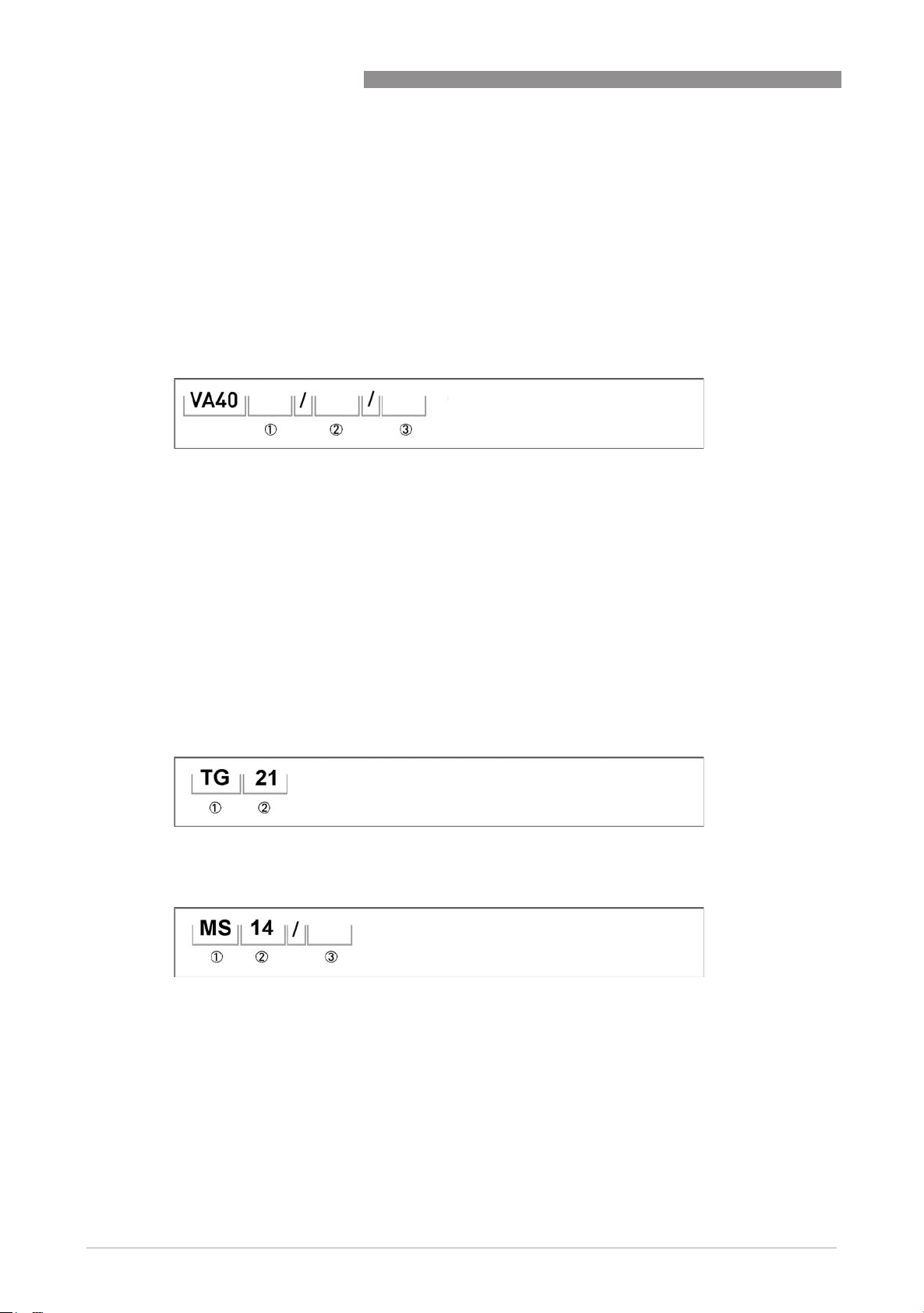
2.2 Description code
The safety description code * consists of the following elements:
1 Type of connection
V - Screw connection
S - Tube socket
F - Flange connection
A - Aseptic connection, conforming to food standards
VA40
2 Material of the connection
R - Stainless steel 1.4404 (316 L)
ST - Steel, electroplated and chromized
PV - Platics PVDF
3 Limit switches
K1 - one limit switch
K2 - two limit switches
* positions which are not needed are omitted (no blank positions)
Safety description code TG21:
1 Inserting limit switch
2 Version 21
Safety description code MS14:
1 Magnetic switch
2 Reed cartridge 14
3
without Limit switch with connected cable
A - Limit switch with terminal box (standard)
4
www.krohne.com 06/2013 - 4002262402 - MA VA40-Ex-II2G-AD R02 en
Page 5
VA40
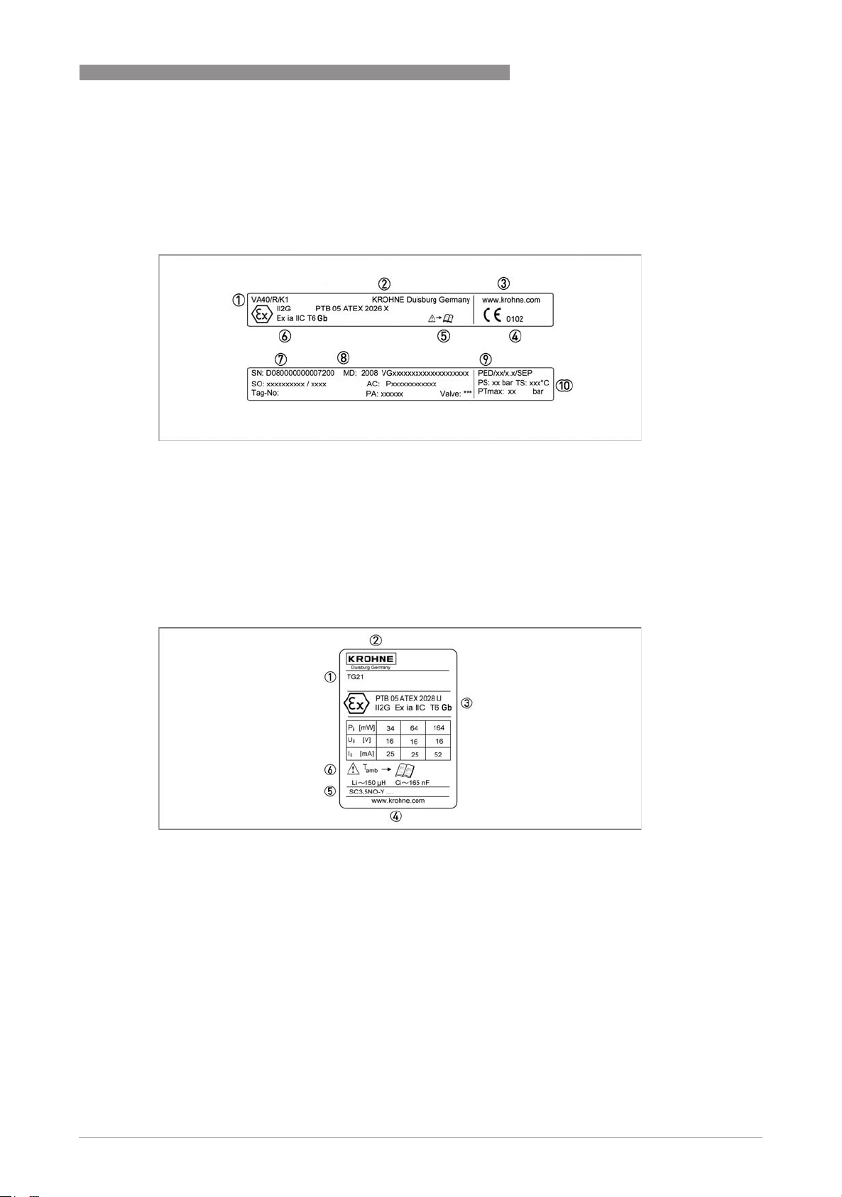
2.3 Marking
The marking of the complete device is shown in the following nameplate. The variable-area
flowmeter is marked on the roundly housing.
1 Type of meter
2 Manufacturer
3 Website
4 Appointed ATEX body
5 Pay regard to manual
6 Ex-data
7 Serial number
8 Year of manufacture
9 PED-data
10 Design data: Temperature & pressure rating
DEVICE DESCRIPTION 2
Marking Limit switch TG21
1 Type
2 Manufacturer
3 Ex data
4 KROHNE website
5 Built-in components
6 Observe Operation and Installation manual
www.krohne.com06/2013 - 4002262402 - MA VA40-Ex-II2G-AD R02 en
5
Page 6

2 DEVICE DESCRIPTION
Marking Limit switches MS14
1 Type
2 Manufacturer
3 Year made
4 Observe Operation and Installation manual
5 Ambient temperature
6 KROHNE website
7 Electrical connection data
VA40
Marking Limit switches MS14A
1 Type
2 Manufacturer
3 Observe Operation and Installation manual
4 Year made
5 Electrical connection data
6 KROHNE website
No Ex marking for MS14 and MS14/A, because the reed limit switch operates as a simple device
and complies to intrinsic safety EN 60079-11 paragraph 5.7.
6
www.krohne.com 06/2013 - 4002262402 - MA VA40-Ex-II2G-AD R02 en
Page 7

VA40
2.4 Flammable products
Atmospheric conditions
An explosive atmosphere is a mixture of air and flammable gases, vapours, mists or dusts under
atmospheric conditions. The following values define it
= -20°C...+60°C / -4°F...140°F and P
T
atm
Outside of this range, no key data are available as to ignition behaviour for most mixtures.
Operating conditions
Variable area flowmeters operate outside of atmospheric conditions, which means that
explosion protection according to Directive 94/9/EC (ATEX) – regardless of the zone assignment
– is fundamentally not applicable due to the lack of key safety data for the interior of the
measuring section.
CAUTION!
Operation with flammable products is only permissible if no explosive fuel/air mixture is formed
on the interior of the flowmeter under operating conditions. The user is responsible for the safe
operation of the flowmeter with regard to the temperatures and pressures of the products used.
In case of operation with flammable products the measuring units must be included in the
periodic pressure tests of the system.
= 0.8...1.1bar.
atm
DEVICE DESCRIPTION 2
2.5 Equipment category
The flowmeters are designed in category II 2G according to EN 60079-0 and EN 60079-11 for use
in zone 1.
2.6 Protection types
The variable area flowmeter is designed with protection type intrinsic safety, protection level "ia"
as per EN 60079-11.
The marking is: II 2G Ex ia IIC T6 Gb
The marking contains the following information:
The marking contains the following information:
The marking contains the following information:The marking contains the following information:
II
II Explosion protection Group II
IIII
2222 Device category 2
GGGG Gas explosion protection
ia
ia Intrinsically safe, protection level "ia"
iaia
IIC
IIC Suitable for gas groups IIC, IIB and IIA
IICIIC
T6
T6 Suitable for temperature classes T6 ... T1
T6T6
Gb
Gb EPL, suitable for zone 1 or zone 2
GbGb
II 2G Ex ia IIC T6 Gb
II 2G Ex ia IIC T6 GbII 2G Ex ia IIC T6 Gb
www.krohne.com06/2013 - 4002262402 - MA VA40-Ex-II2G-AD R02 en
7
Page 8

2 DEVICE DESCRIPTION
2.7 Ambient temperature / temperature classes
Because of the influence of the temperature of the product, no fixed temperature class is
assigned to variable area flowmeters. In fact, the temperature class of a device is a function of
the temperature of both the product and the environment. There is no distinction between
devices with one or two contacts. The classification is outlined in the following tables.
The tables take into account the following parameters:
• Ambient temperature T
• Product temperature T
INFORMATION!
The maximum permissible product temperatures listed in the tables are valid under
the following conditions:
•
The measuring device is installed and operated in accordance with the installation
instructions in the manual.
•
It must be ensured that the flowmeter is not heated by the effects of additional heat radiation
(sunshine, neighbouring system components) and thus operated above the permissible
ambient temperature range.
•
Insulation must be limited to the piping.
Unobstructed ventilation of the indicator part must be ensured.
amb.
m
VA40
Maximum permissible product and ambient temperatures TG21
Supply Type 1 Type 2 Type 3
Temperature class T6 T5 T4...T1 T6 T5 T4...T1 T6 T5 T4...T1
Max. medium
temperature [°C]
Max. medium
temperature [°F]
70 85 95 60 75 95 35 50 70
158 185 203 140 167 203 95 122 158
Maximum permissible product and ambient temperatures MS14/.
The maximum medium and ambient temperature is -20°C...+85°C / -4°F...+185°F.
These values may be limited by the information contained in the installation and operating
instructions. The maximum values listed in the installation and operating instructions must be
taken into consideration.
8
www.krohne.com 06/2013 - 4002262402 - MA VA40-Ex-II2G-AD R02 en
Page 9

VA40
2.8 Electrical data
Limit switch TG21
The built-in intrinsically safe NAMUR limit switch TG21 may only be connected to isolation
switching amplifiers with separated intrinsically safe circuits to EN 60947 -5 -6 with the
following max. values:
Maximum values of the power supply units
Supply Pi [mW] Ui [V] Ii [mA]
Type 1 34 16 25
Type 2 64 16 25
Type 3 169 16 52
When connecting to intrinsically safe circuits, take into consideration the following maximum
values per circuit for the energy stores.
DEVICE DESCRIPTION 2
Ci [nF] L
165 150
[µH]
i
Limit switch MS14
Built-in limit switch MS14 may only be connected to separate intrinsically safe circuits with the
following maximum values:
Pi [W] Ui [V] Ii [mA]
1 30 100
When connecting to intrinsically safe circuits, take into consideration the following maximum
values per circuit for the energy stores.
Ci [nF] L
0 0
[µH]
i
www.krohne.com06/2013 - 4002262402 - MA VA40-Ex-II2G-AD R02 en
9
Page 10

3 INSTALLATION
3.1 Installation
Installation and setup must be carried out according to the applicable installation installation
standards (e.g. EN 60079-14) by qualified personnel trained in explosion protection. The
information given in the Installation and Operation Instructions and the Supplementary
Installation and Operation Instructions must always be observed.
Variable area flowmeters must be installed in such a way that
• There is no danger from mechanical impact effects.
• There are no external forces affecting the indicator part.
• The device is accessible for any visual inspections that are necessary, and can be viewed from
all sides.
• The nameplate is clearly visible.
• It can be operated from a location with secure footing.
CAUTION!
The manufacturer is not liable for any damage resulting from improper use or use other than the
intended purpose. This applies in particular to hazards due to insufficient corrosion resistance
and suitability of the materials in contact with product.
VA40
10
www.krohne.com 06/2013 - 4002262402 - MA VA40-Ex-II2G-AD R02 en
Page 11

VA40
4.1 General notes
The separate intrinsically safe signal circuits of protection level "ia" or "ib" are electrically
connected in the terminal compartment of the plug housing for the limit switch type TG21 and
MS14. The limit switch MS14 ist connected to the strandes wires. The terminal housing must
have a protection class of min. IP20. Take note of the polarities given for the limit switch TG21.
Connecting cable
The connecting cables must be selected according to prevailing installation standards (e.g.
EN 60079-14).. The outer diameter of the connecting cable must be within the sealing range of
the cable entry. The connecting cables must be fixed and laid in such a way as to be sufficiently
protected against damage.
All cores that are not used must be securely connected to the ground potential of the hazardous
area or carefully insulated against each other and against ground (test voltage ≥ 500 V
4.2 Grounding and equipotential bonding
If the device is not sufficiently electrostatically grounded via the process cables, an additional
earth connection must be established using the ground terminal. The location of the ground
connection on the back rail is shown below. This connection only ensures electrostatic
grounding of the device and does not meet the requirements for equipotential bonding.
ELECTRICAL CONNECTIONS 4
).
eff
Grounding connection 1
www.krohne.com06/2013 - 4002262402 - MA VA40-Ex-II2G-AD R02 en
11
Page 12

5 OPERATION
5.1 Start-up
Make the following checks before starting up the device:
• Suitability of the materials used for the measuring unit and for the gaskets for adequate
resistance to corrosion from the process product.
• Correct connection of the built-in electrical components.
• Correct setting of the limit switches.
• Electrostatic grounding of the instrument.
5.2 Operation
Setting of the limit switches may be carried out during operation. For this unscrew the mounting
equipment. After setting the limit switch unit to the switchpoint fix it with the fastening screw.
Additionally the switching behavior of the limit switch TG21 is to adjust in its terminal box. The
switching function of the MS14 is determined by the fitting position of the reed contact. A
changing of the position during operation is permitted. Close the unit immediately.
VA40
5.3 Electrostatic charge
In variable area flowmeters, it is possible under field conditions for charge separation to occur in
the measuring tube due to the transport of non-conductive fluids and/or when the flow comes
into contact with non-conductive built-ins.
In glass devices, it is basically possible for the electrostatic field generated inside the measuring
tube to "punch through" to the outside of the device. For that reason, variable area flowmeters
need to be permanently grounded by the operator by way of the process connections in order to
allow discharge of electrostatic build-up.
The operator is also responsible for extending the ground continuity of the process pipeline.
If grounding cannot be made via the process connections, e.g. top and bottom connection blocks
are made of plastic, the flowmeter should be connected to the local ground potential via the
connection to ground described in the section entitled "Grounding and equipotential bonding".
This connection only ensures electrostatic grounding of the device and does not meet the
requirements for equipotential bonding.
When dust-free gases or liquids are measured, the flow rate should not exceed 5 times the
nominal flow rate. The max. allowable working pressure PS printed on the type nameplate is to
be noted. The conductivity of the medium must be min. 1000pS/m.
12
www.krohne.com 06/2013 - 4002262402 - MA VA40-Ex-II2G-AD R02 en
Page 13

VA40
6.1 Maintenance
Maintenance work of a safety-relevant nature within the meaning of explosion protection may
only be carried out by the manufacturer, his authorised representative or under the supervision
of authorised inspectors.
For systems in hazardous areas, regular tests are required in order to maintain the proper
condition.
The following checks are recommended:
• Checking the housing, the cable entries and the feed lines for corrosion and/or damage.
• Checking the measuring unit and the piping connections for leakage.
• Checking the measuring unit and the indicator for dust deposits.
• Including the flowmeter in the regular pressure test of the process line.
CAUTION!
Avoid electrostatic charges when cleaning the sight window!
SERVICE 6
6.2 Dismantling
Exchanging the limit switches
The limit switch is to replace with an identical spare part in accordance with safety guidelines.
Exchanging the entire device
Removal and installation are the responsibility of the operator.
If at all possible, the meter should be electrically isolated before removing and replacing the
indicator. If that is not possible, the basic conditions for intrinsic safety (e.g. no grounding or
connection of different intrinsically safe circuits to one another) must be observed during
dismantling.
CAUTION!
•
Pressurized pipes have to be depressurized before removing the measuring unit.
•
In the case of environmentally critical or hazardous products, appropriate safety precautions
must be taken with regard to residual liquids in the measuring unit.
•
New gaskets have to be used when re-installing the device in the piping.
www.krohne.com06/2013 - 4002262402 - MA VA40-Ex-II2G-AD R02 en
13
Page 14

7 NOTES
VA40
14
www.krohne.com 06/2013 - 4002262402 - MA VA40-Ex-II2G-AD R02 en
Page 15

VA40
NOTES 7
www.krohne.com06/2013 - 4002262402 - MA VA40-Ex-II2G-AD R02 en
15
Page 16

KROHNE product overview
• Electromagnetic flowmeters
• Variable area flowmeters
• Ultrasonic flowmeters
• Mass flowmeters
• Vortex flowmeters
• Flow controllers
• Level meters
• Temperature meters
• Pressure meters
• Analysis products
• Products and systems for the oil & gas industry
• Measuring systems for the marine industry
Head Office KROHNE Messtechnik GmbH
Ludwig-Krohne-Str. 5
47058 Duisburg (Germany)
Tel.:+49 (0)203 301 0
Fax:+49 (0)203 301 10389
info@krohne.de
The current list of all KROHNE contacts and addresses can be found at:
© KROHNE 06/2013 - 4002262402 - MA VA40-Ex-II2G-AD R02 en - Subject to change without notice.
www.krohne.com
 Loading...