

Page 1
GR/PRINTO
©
KROHNE 12/2000 D 31 IF10 02 D
Installation and
operating instructions
ALTOSONIC
Ultrasonic Flowmeters
UFM 800
Variable area flowmeters
Vortex flowmeters
Flow controllers
Electromagnetic flowmeters
Ultrasonic flowmeters
Mass flowmeters
Level measuring instruments
Communications engineering
Engineering systems & solutions
16
6
5
4
7
18
3
8
9
8
2
11
10 12 13
14 15
14
17
15
Page 2

Contents Page
1 Description of the installation 3
1.1 Material delivered for Single Beam (SB) 3
1.2 Material delivered for Double Beam (DB) 3
2.0 Sensor distance calculation 4
3.0 Mounting of the sensor supports and the square pipe 5
4 Sensor alignment 5
4.1 Fluid alignment 6
4.2 Laser alignment 7
5.0 Welding of the sensors on the sensor support 7
6.0 Mounting of the sensors 8
7.0 Cabling, connection, final mounting 8
8.0 Programming the UFC 500 converter 9
9.0 Zero-point measurement 10
12/2000Installation and operating instructions UFM 800 W / UFM 800 C
2
Page 3

Installation and operating instructions UFM 800 W / UFM 800 C
3
12/2000
1.0 Description of the installation
The supplied installation is basically the same as the UFM 400F (single beam SB) or the UFM 500F (double beam DB). The difference is that
the sensors are welded in an existing steel pipe. Because wet calibration is impossible, the primary constant (GK) will be calculated from the
geometry. If a reference value of the flow rate is available, the installation can be calibrated on site.
– 2 FS 500W sensors
– 2 sensor supports
– 2 protected sensors cables (length depending on outer diameter)
– 1 square pipe with 2 threaded holes
– 1 connection box, incl. print, gasket, screws and cover
– 1 connection cable MR02 between the connection box on the pipe and the signal converter (length 5-50 m)
– UFC 500F signal converter with wall mounting kit
– 1 tube of acoustic coupling grease
– 1 bottle Silicon oil AK 2000
1.1 Material delivered for SB
– 4 FS 500W sensors
– 4 sensor supports
– 4 protected sensors cables (length depending on outer diameter)
– 1 square pipe with 4 threaded holes
– 1 connection box, incl. print, gasket, screws and cover
– 1 connection cable MR02 between the connection box on the pipe and the signal converter (length 5-50 m)
– UFC 500F signal converter with wall mounting kit
– 1 tube of acoustic coupling grease
– 1 bottle Silicon oil AK 2000
1.2 Material delivered for DB
Page 4

12/2000Installation and operating instructions UFM 800 W / UFM 800 C
4
2.0 Sensor distance calculation
For calculating the sensor distance A it is necessary to know the internal diameter Di. For centering the sensor holders it is necessary to know the
wall thickness t and the external diameter D.
Drawing 1: Single beam flowmeter, principle dimensions for sensor positioning and GK-calculation A = Di + 11mm
Drawing 2: Double beam flowmeter, principle dimensions for sensor positioning and GK – calculation
In drawing 2:
α = 360° ⋅ ((Di ⋅ π/12 – 3,9) / (Di ⋅ π)
A = Di ⋅ 0,866 ⋅ √ 1 – tg
2
α + 7,8
1 + tg
2
α
The distance, measured over the outside of the pipe between the sensors 1 and 2 then equals 180 - 2α⋅ π⋅ D
Ο
360
The distance, measured over the outside of the pipe between the sensors 1 and 4 then equals 2α⋅ π⋅ D
Ο
Page 5

Installation and operating instructions UFM 800 W / UFM 800 C
5
12/2000
3.0 Mounting of the sensor supports and the square pipe
●
Mark the centers of places where the sensors must be fixed on the tubes (Drawing 1/2 SB/DB).
●
Drill holes at these places of diameter 40 mm (Drawing 3)
●
Machine the sensor supports so that they have the right curve for the pipe (outside diameter) and the right length (Drawing 3). Weld the
sensor supports on the pipe perpendicular to the pipe wall and around the holes, so that the end of the supports is situated at 40 mm from
the internal side of the pipe wall. Due to the welding, the thread of the sensor support can be deformed, by using a thread tap of 42 x 1.5
this can be solved.
●
Grind the interior of the pipe and sensor supports to get rid of burrs. Take care not to damage the thread inside the sensor supports.
●
Weld the square pipe on the appropriate place on the pipe (Drawing 1/2). The square pipe must be welded all around to create a closed
atmosphere inside (environmental protection class IP 67/68).
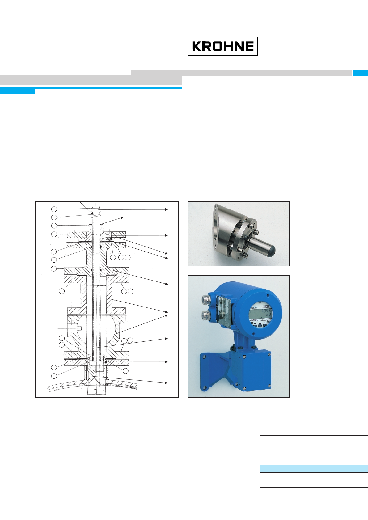
Drawing 3: Sensor FS 500W. 1. Cover 2. Nut, 3. Pies guiding, 4. Sensorbody, 5. Sensor Support, 6. O-ring, 7. Piezo
4.0 Sensor alignment
The sensors of each acoustic path must be aligned to have an optimum acoustic signal transfer. The best way to obtain this is by fluid alignment,
where the pipe is filled with fluid and the sensor position is optimized by monitoring the acoustic signal transfer. When this is impossible, the
sensor can be aligned optically. For this method it is necessary to have access to the inside of the pipe. The end result is that the acoustic
windows are parallel and on the same axis. This is acceptable for the acoustic signal transfer.
For single beam (SB) installations there is only one ultrasonic path and two sensors (Drawing 1). This path is named path 1 and it is composed
of sensors 1 and 2. For double beam (DB) installations there are two acoustic paths and four sensors (Drawing 2). The upper path is path 1,
composed of sensors 1 and 2. The lower path is path 2, composed of sensors 4 and 3. It is very important that both acoustic paths have the
same signal strength. This is only possible to optimize with fluid alignment, or with laser alignment.
Page 6

12/2000Installation and operating instructions UFM 800 W / UFM 800 C
6
4.1 Fluid alignment
For a correct alignment a Service Adapter Board is required as shown in the diagram.
Note:
SIGNAL CONTROL SIGNAL DETECTION SIGNAL PROCESSING
1/2 path 1/2 selection TrL trigger level TrC trigger course
U/D pulse direction TW time window TrD trigger delay
/SP start pulse Tff trigger flip-flop DS dual slope
T1-4 start pulse sensors BAGC received pulse TrF trigger time
INR received pulse before the AGC /TrDA trigger delay
3/4 trigger point AGCL AGC level amplified
for DS-calibration AAGC received pulse
the AGC
The signals printed in “italic” are not described since they are not necessary for the explanation of the alignment.
The service adapter
must be connected
with a flatcable to the
Service connector on
the converter just
behind the display
board.
Page 7

Installation and operating instructions UFM 800 W / UFM 800 C
7
12/2000
Procedure for the liquid alignment by using the service adapter board:
1. Align the four sensors physically
2. Connect the sensor cables (1,2, 3 and 4) to the converter as described in item 7
3. Install the service adapter board
4. Connect the power supply
5. Program the converter as described in item 8 (diameter, time window etc.)
6. Select in address 5.2.6. path 1 (i.e. sensors 1 and 2)
7. Measure the DC voltage on AGCL (red) and GROUND (black)
8. Manipulate one sensor of sensor pair 1 for the highest voltage
9. Manipulate the other sensor of sensor pair 1 for the highest voltage
10. Select in address 5.2.6 path 2 (i.e. sensors 3 and 4)
11. Manipulate one sensor of sensor pair 2 for the highest voltage
12. Manipulate the other sensor of sensor pair 2 for the highest voltage
13. Disconnect the service adapter board
4.2 Laser alignment
When fluid alignment is not possible it is possible to align the sensors using a laser-beam. This means that the acoustic windows of the sensors
of each acoustic path will be parallel to each other and on the same axis. It is necessary to have access to the inside of the tube.
Special equipment needed:
●
Laser alignment tool (to be ordered separately)
Align the sensor with the laser alignment tool as follows:
●
Screw the sensors in the sensor supports until the end. Verify that the sensors are not sticking into the inside diameter of the pipe, else
unscrew until the sensors are flush. Then unscrew each sensor until the acoustic window is facing the opposite sensor of the same path
(Drawing 1/2 SB/DB).
●
Fix these sensors on this position with a welding spot.
●
Check the alignment once more.
5.0 Welding of the sensors on the sensor support (after alignment with fluid)
Before welding around the sensors completely, remove the inner parts (Drawing 3) from the sensor bodies. Keep the internal parts of each sensor
together in a clean box or plastic bag. Cover the reaming sensor body with a protecting screw to prevent dust and dirt from getting into the sensor
body during welding and grinding. Weld the sensor bodies all around on the sensor support (Drawing 3) and let them cool down before mounting
the internal parts. Due to the welding, the thread of the sensor body can be deformed, by using a thread tap of 20 x 1.5 this can be solved.
Mount the internal parts of the sensors as described in item 6 on the next page.
Page 8

12/2000Installation and operating instructions UFM 800 W / UFM 800 C
8
6.0 Mounting of the sensors
●
Mark the connection box of sensors 1 and 4 with a "P”, mark the connection box of sensors 2 and 4 with a "N” (See Drawing 2).
●
Clean the inside of the sensor holder using acetone and dry with compressed air.
●
Clean the piezo crystal.
●
Glue the crystal to the cupper sheet at the front end of the piezo guiding, using the acoustic coupling grease.
NOTE:
With a "P” type sensor: the crystal side marked with a green dot must face the piezo guiding.
With a "N” type sensor: the crystal side marked with a green dot must NOT face the piezo guiding.
●
Install the insulation ring around the crystal.
●
Put 3 drops of Silicon Oil AK 2000 to the free face of the crystal. Make sure no air-bubbles remain on the crystal or in the oil.
●
Slide the holder with crystal to the housing.
●
Try to direct the holder into the right direction.
●
Fasten the holder with the spring-loaded washer and nut.
●
Click the cable connector to the sensor.
●
Match the cable numbers to the sensor numbers according to Drawing 1 or 2.
7.0 Cabling, connection, final mounting
Connect the sensor cables to the corresponding sensors (numbering) on one side and to the square pipe on the other side:
Drawing 7: Sensor cable with Anaconda protecting hose. 1. Anaconda Sealtite armoured hose
with nut, sealing and insert, pre-mounted, 2. Silicon protection (glass fiber reinforced), 3. coaxial
signal cable, 4. Label with sensor number, 5. cable gland, 6. SMB connector
●
Feed the SMB-connector (6) through the threaded hole in the sensor body and screw the cable gland (5) in the sensor body and tighten
vigorously. Connect the SMB-connector to the electrical connection plug. Place the Anaconda hose on the cable gland and screw the nut
(it can rotate over the sealing). Tighten it vigorously. The sealing must come out of the gland to ensure watertight mounting.
●
Screw the covers (1) on the sensors with the closing O-ring (7) (Drawing 3).Apply a little grease on the O-ring and take care that the O-ring is
well placed and not damaged by the thread, to establish a good environmental protection (IP 65/68). The cover must be screwed until the
O-ring is no longer visible and tightened.
●
Feed the SMB-connector on the opposite side through the hole in the square pipe and connect the Anaconda hose as described above to the
square pipe.
●
Fix the connection box on the square pipe, while placing the silicon gasket and connect SMB-connectors of the sensor cables to the print in
the connection box.
●
Fix the connection print in the connection box.
●
Mount the signal converter to the wall with its wall mounting support.
Page 9

Installation and operating instructions UFM 800 W / UFM 800 C
9
12/2000
8.0 Programming the UFC 500 converter
●
Connect the MR02 or MR04 cables to the connection box on the square pipe on one end and to the connection box under the signal converter
on the other end. Connect the right connectors to the right place (numbering!). Fix the cable gland PG16 tightly to establish a good environmental protection.
●
Close both connection boxes, while taking care that the gaskets are well placed.
●
Connect the power supply and output cable to the converter (Installation and Operating Manual 400/500).
●
Fill the tube with fluid and check the signals in the UFC500 by using the procedure 4.1.
TRIGGER LEVEL
See UFM 500 K/F Manual.
Program the following values in the concerning functions. Other functions can be altered if desired (output, time constant, low flow cut off).
Nr. Function Description
3.1.1. FULL SCALE Desired flowrate for full scale (=100%)
3.1.5. METER SIZE Exact internal diameter in mm or inch
3.1.6. GK VALUE Primary constant value: acc. to PC calculations
5.2.6. SEL PATH Single Beam: Path 1
Double Beam: Path 1 + 2
5.3.1. T. WINDOW ≥ DN 100/4 33 µS
> DN 100/4 ca. 70% of transit time for water (see Fct. 3.2.4.)
entry code for menu 5:
Drawing 10: Trigger adjustment
The optimum value of the trigger-level is in between the values of the first and second peak.The factory setting of 200 mV is suitable for most
applications. In some cases adjustment may be necessar y.
Page 10

12/2000Installation and operating instructions UFM 800 W / UFM 800 C
10
9.0 Zero-point measurement
For ultrasonic flowmeters it is important to have a good zero-point. For making a zero-point it is very important to have a situation where the flow
is absolutely zero. If that is not possible the default zero-point can be used, which is a good approximation.
●
Have the fluid flow at a high flow rate for at least five minutes. Stop the flow and shut down the upstream and downstream valves (if available).
●
Let the fluid stabilize until the displayed flow rate becomes stable. (At least a few minutes, but even longer for large diameters (> DN 300).
●
Make a zero-point measurement (Fct. 3.1.4.) and check if the display comes to zero. Else repeat the zero-point measurement until a stable
zero-point is obtained.
Now the UFM 800W ultrasonic flowmeter should be operating in correct way.
 Loading...