

Page 1
KROHNE 01/94 7.30718.32.00
©
GR
Installation and
operating instructions
UFM 600 T
ALTOSONIC
Variable area flowmeters
Vortex flowmeters
Flow controllers
Electromagnetic flowmeters
Ultrasonic flowmeters
Mass flowmeters
Level measuring instruments
Communications engineering
Engineering systems & solutions
Switches, counters, displays and recorders
Heat metering
Pressure and temperature
Page 2

All rights reserved. No part of this publication may be copied or published
by means of printing, photocopying, microfilm or otherwise without prior
written consent of KROHNE Altometer.
This restriction also applies to the corresponding drawings and diagrams.
KROHNE Altometer has the right to change the parts or specifications at
any time whitout prior or direct notice to the client. The contents of this
publication are subject to change without notice.
This publication is to be used for the standard version only. Thus KROHNE
Altometer cannot held responsible for any damage resulting from the
incorrect application of this publication to the version actually delivered to
you.
For additional information regarding configuration, maintenance and repair,
contact the technical department of your supplier.
This publication has been written with great care. However, KROHNE
Altometer cannot be held responsible, either for any errors occuring in this
publication or their consequences.
PM 04.97.Rev.3
Page 3

ALTOSONIC
A INTRODUCTION ................................................................6
B SYSTEM DESCRIPTION ................................................. 8
B.1 Measuring Principle ........................................................... 8
B.2 Measuring System............................................................. 10
B.3 Equipment......................................................................... 12
B.4 Controls and Connections ................................................. 14
B.5 Transducers and Mountings ............................................. 16
B.6 Display and Data Storage .................................................. 17
B.7 Direct Output..................................................................... 18
B.8 Power Supply.................................................................... 18
C OPERATION .................................................................... 20
C.1 Initial Set-Up...................................................................... 20
C.1.1 Installation of mounting rails............................................... 21
C.1.2 Programming the application parameters .......................... 24
C.1.3 Installation of the transducers ............................................ 26
C.1.4 Zero set / zero point calibration ......................................... 28
C.2 Start Up Menu................................................................... 30
C.2.1 Enter start up menu........................................................... 30
C.2.2 Application Functions ........................................................ 30
C.2.3 Plausibility check ............................................................... 34
C.3 Error Detection .................................................................. 35
C.3.1 Low signal marker function................................................ 35
C.3.2 Error messages ................................................................. 36
C.4 Data Collection.................................................................. 38
C.4.1 Data collection procedure.................................................. 38
C.4.2 Transfer to PC (data and parameters)................................ 40
C.4.3 Parameter handling ........................................................... 41
C.5 Quit / Reset Menu ............................................................. 42
C.6 Direct Output Ports ........................................................... 44
C.6.1 General ............................................................................. 44
C.6.2 Output hold ....................................................................... 44
C.6.3 Current output................................................................... 44
C.6.4 Frequency output .............................................................. 44
C.6.5 Connection diagrams .......................................................45a
C.7 Trouble Shooting............................................................... 46
UFM 600 T
2
Contents
Page 4

D PROGRAMMING MODE................................................. 48
D.1 General ............................................................................. 48
D.2 How to Program................................................................ 49
D.3 List of Functions ................................................................ 52
D.4 Main Menu: 3.0.0 INSTALLATION .................................... 54
D.5 Main Menu: 2.0.0 TEST..................................................... 72
D.6 Parameter errors ............................................................... 74
E MAINTENANCE............................................................... 76
E.1 Fuse .................................................................................. 76
F TECHNICAL DATA.......................................................... 78
F.1 General ............................................................................. 78
F.2 Transducers & Clamp-on Set ............................................ 79
F.3 Signal Converter ................................................................ 80
APPENDIX 1 : Pipe Material Sonic Velocities .................. 84
APPENDIX 2 : Sonic Velocities of Liquids ....................... 85
APPENDIX 3 : Sonic Velocity Calculation........................ 86
APPENDIX 4 : Exponential Notation.................................87
APPENDIX 5 : Default Settings + Example of
Output Parameters .................................. 88
APPENDIX 6 : Spare Parts ............................................. 90
3
A
B
C
D
E
F
Page 5

Fig. B.1 : Measuring principle........................................................... 8
Fig. B.2 : System diagram................................................................ 11
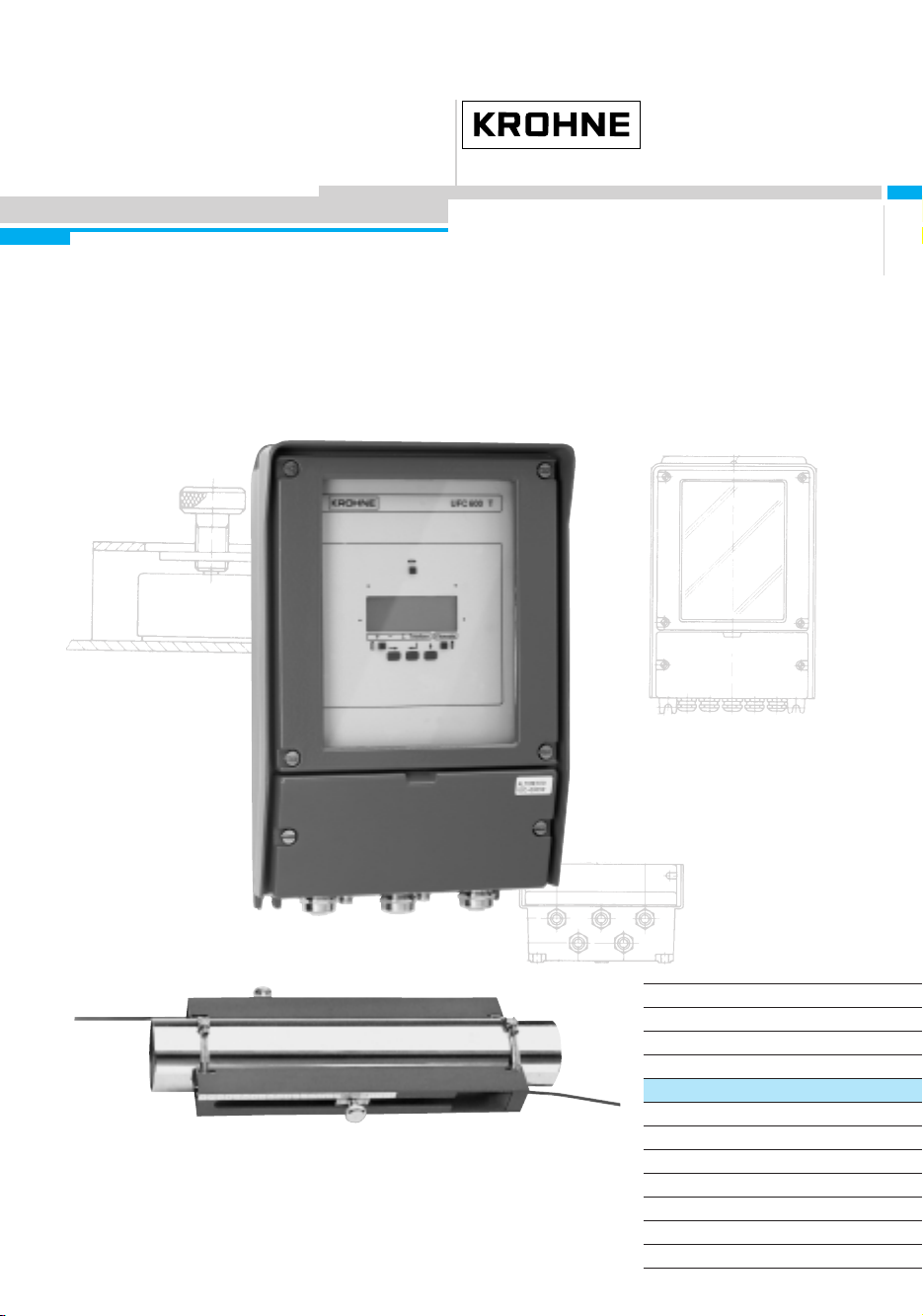
Fig. B.3 : UFM 600 T with all equipment displayed........................... 13
Fig. B.4 : UFC 600 T converter ........................................................ 15
Fig. B.5 : Transducers and unit ........................................................ 16
Fig. C.1 : Mounting rail ..................................................................... 22
Fig. C.2 : Mounting rails fitted on the pipe ........................................ 22
Fig. C.3 : Mounting positions............................................................ 23
Fig. C.4 : Position of transducer and cable....................................... 26
Fig. C.5 : Upstream and downstream connections........................... 27
Fig. D.1 : Entering the programming mode....................................... 49
Fig. D.2 : Low flow cutoff ................................................................. 55
Fig. D.3 : Bi-directional flow (I).......................................................... 61
Fig. D.4 : Flow direction indication (I) ................................................ 61
Fig. D.5 : Positive flow (I) .................................................................. 61
Fig. D.6 : Negative flow and output (I)............................................... 61
Fig. D.7 : Bi-directional flow (F)......................................................... 63
Fig. D.8 : Flow direction indication (F) ............................................... 63
Fig. D.9 : Positive flow (F) ................................................................. 64
(I) current output
(F) frequency output
4
ALTOSONIC
List of illustrations
UFM 600 T
Page 6

5
Page 7
System Description
The Altosonic UFM 600 T is an ultrasonic flowmeter which can easily be
clamped on existing pipelines with inner diameters between 50 mm and
3000 mm (2" to 120") and pipe wall thicknesses up to 40 mm.
Measurement is performed obstructionless, without changing the existing
pipework and without any headloss.
The UFM 600 T is an economical solution for all kinds of flow measurements of liquids containing no or little solid particles or gas.
Examples are: cooling water, waste water, oil, acids, bases etc.
6
ALTOSONIC
Introduction
UFM 600 T
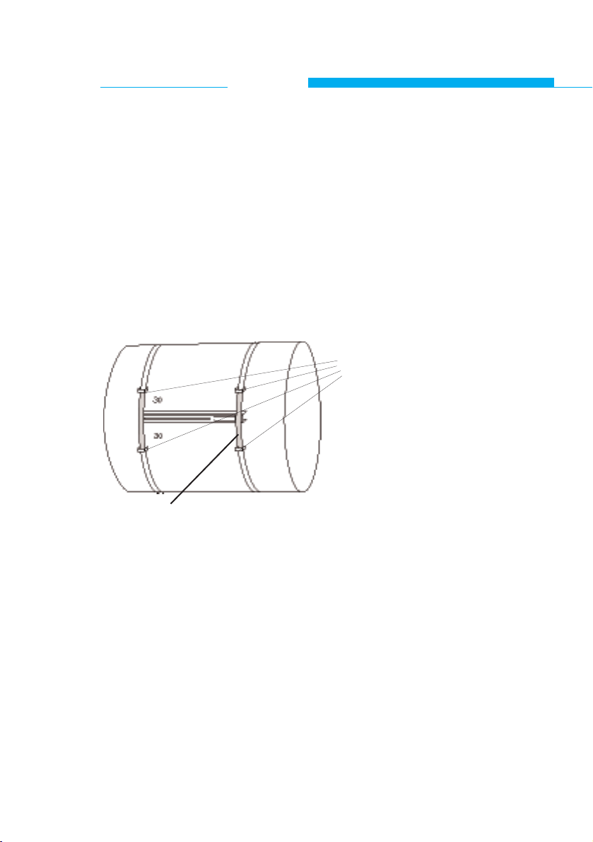
little bows welded
on the tube
Mounting strap
At mounting on diameters > DN 1600, we recommend to weld 4 little
bows on the tube as indicated in the sketch.
See also Chap. C.1.1.
Page 8

7
Page 9
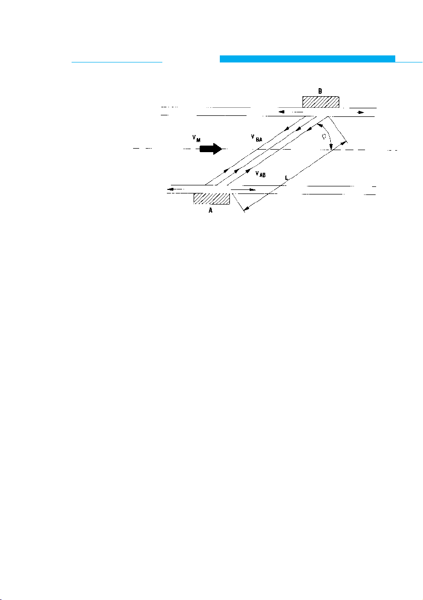
B.1 Measuring Principle
Fig. B.1 : Measuring principle
A sound wave that is sent in the direction of the flow through
a medium will travel faster than one that is sent in the opposite direction.
This principle is used in the ultrasonic transit time flowmeter.
Two ultrasound transmitters/receivers are fitted on opposite
sides of the pipe section as shown in Fig. B.1.
Initially transducer A transmits an ultrasonic sound signal that
will be received by transducer B. The time lapse tABbetween
transmission and reception is measured.
Then the functions of both probes are reversed and the transit time tBAin the opposite direction is measured.
From tABand t
BA
the actual flow can be calculated taking into
account the following factors:
- pipe diameter
- wall thickness
- lining thickness, if applicable
- sonic velocity in the liquid
- sonic velocity in the pipe material
- sonic velocity in the pipe lining material, if applicable
Measurements are taken continuously.
NOTE: Each transducer transmits and receives ultrasound signals.
8
ALTOSONIC
System Description
UFM 600 T
Page 10

9
Page 11

B.2 Measuring System
A microprocessor controls the transducers via an analog/
digital interface and calculates the actual flow.
The control program is stored in EPROM memory.
Parameters for the application and processing the data are
entered via the keyboard.
A liquid crystal display is used for the indication of all
measuring data.
All data collected in the field can be stored in RAM memory
and transferred to an IBM compatible PC via an RS 232 output; the same applies to the parameter settings.
Both current and frequency output signals are available for
auxiliary readout and/or control purposes.
Figure B.2 shows a diagram of the flowsystem.
10
ALTOSONIC
System Description
UFM 600 T
Page 12
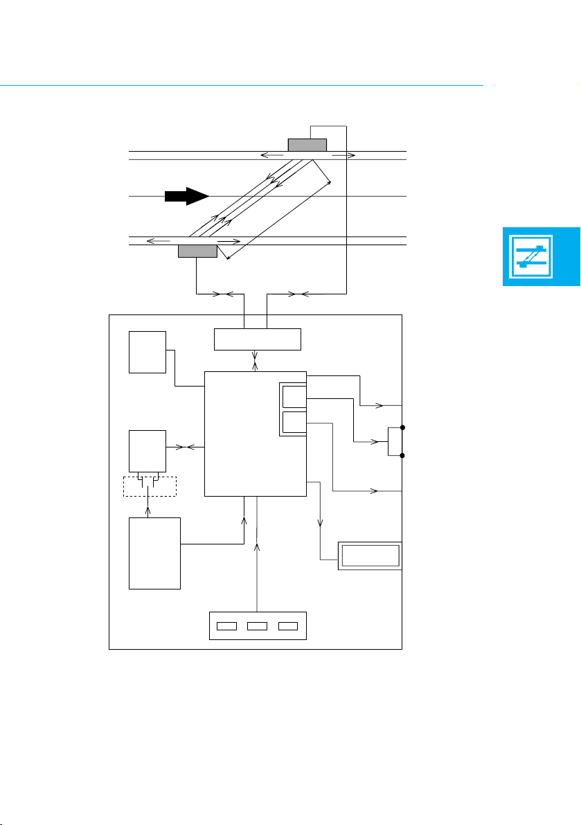
Fig. B.2 : System diagram
11
EEPROM
(µP1)
SENSOR
FLOW
SENSOR
UP DOWN
SIGNAL
PROCESSOR
RAM
POWER
SUPPLY
MICRO
PROCESSOR
(µP2)
KEYBOARD
RS 232 OUTPUT
CURRENT OUTPUT*
FREQUENCY*
OUTPUT
DISPLAY
*) galvanically insulated
Page 13

B.3 Equipment
The UFM 600 T flowmeter is fitted in a sturdy case.
Figure B.3 shows the UFM 600 T with all items
displayed:
1. UFC 600 T signal converter (1x)
2. RS 600 clamp on transducer (2x)
3. Shielded cable (coax) (2x)
4. Grounding cable (1x)
5. Small mounting strap (2x)
6. Large mounting strap (4x)
7. Mounting rail (2x)
8. Acoustic coupling grease (1x)
9. Measuring tape (5m) (1x)
- Manual and data sheets
- 3,5" diskette
10. Magnet bar (1x)
12
ALTOSONIC
System Description
UFM 600 T
Page 14
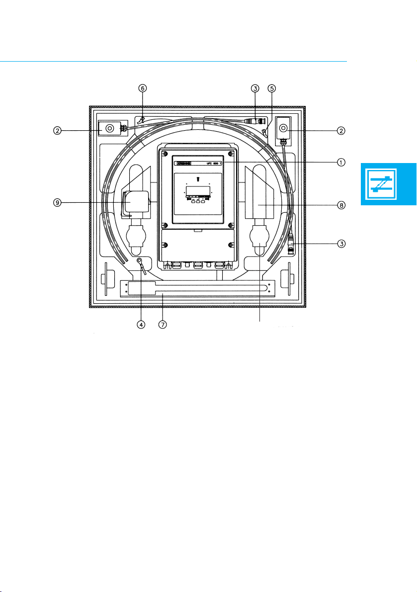
Fig. B.3 : UFM 600 T with all equipment displayed
13
➉
Page 15

B.4 Controls and Connections
Figure B.4 shows the controls and connections of the
flowmeter unit.
1 Liquid crystal display
2 Keyboard (3 keys)
3 Power supply (term. 11,12)
4 Connector for upstream transducer
5 Connector for downstream transducer
6 RS 232 output for PC
7 mA-Output (term. 5, 6)
8 Frequency output (term. 4,.4.1, 4.2)
9 Hall contacts
14
ALTOSONIC
System description
UFM 600 T
Page 16
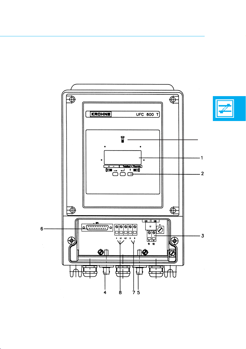
Fig. B.4 : UFC 600 T converter
15
9
Page 17
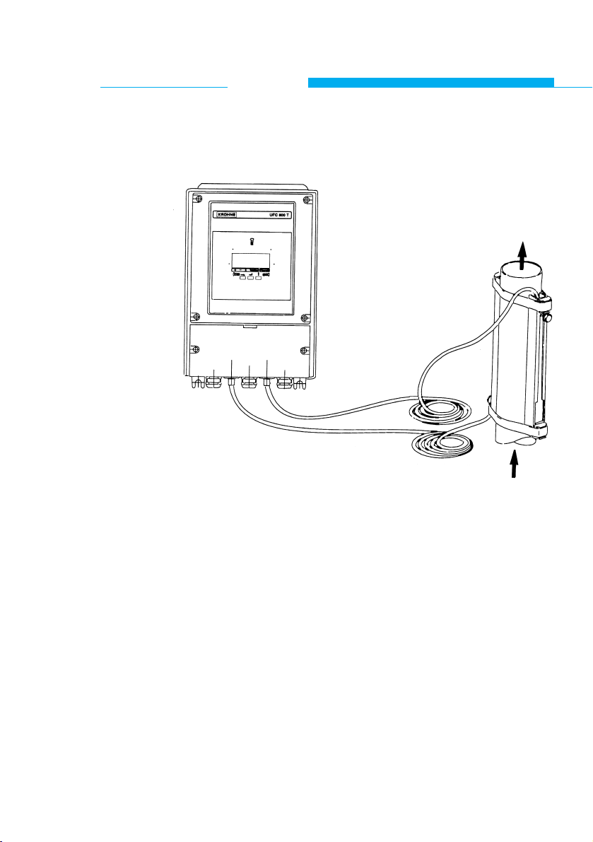
B.5 Transducers and Mountings (see Fig. B.5)
Fig. B.5 : Transducers, signal converter and auxillary items
Two mounting rails are clamped against the pipe wall by two
straps.
The transducers can slide inside the mounting rails to obtain
the correct distance between them. The transducers are then
tightened firmly against the pipe wall.
Coupling grease is used between the transducers and the
pipe wall to provide a good transfer of the ultrasound signal
through the pipe material.
The transducers are connected to the control unit by means
of two shielded cables.
16
ALTOSONIC
System description
UFM 600 T
Page 18

B.6 Display and Data Storage
Display:
The following display options are available:
- Actual flow rate and direction.
- Total positive and negative flow volume since the
start of the measuring session.
- Absolute flow volume since the start of the
measuring session.
- Transit time of the acoustic signal.
- Error messages.
- Back lit function of the display.
Since the display shows only one read out at a time, they can
be viewed sequentially.
Collect data:
At a programmable interval, all flow information selected
to be displayed can be stored and sent to a PC via the
RS 232 output. Also the parameter settings can be send to a
PC.
17
Page 19

B.7 Direct Output
Both current and frequency output signals are available for
control purposes. These can be either analog signals or just
flow direction indicator signals.
To avoid adverse effects on equipment connected to the
flowmeter a signal hold function can be activated; this is
important if the flowmeter is being used as part of a control
loop. When you terminate the measuring session the last
output signal can be maintained.
B.8 Power Supply
The flowmeter can be delivered in two versions for different
power sources:
- AC Power supply 85 - 264 VAC
- DC power supply 18 - 32 VDC
When the unit is switched off, the data stored in the volatile
memory is maintained by a backup battery on the microprocessor board.
This battery is capable of supporting the RAM for at least
5 years.
18
ALTOSONIC
System description
UFM 600 T
Page 20

19
Page 21

C.1 Initial Set-Up
The main steps of the installation procedure of the flowmeter
are:
1 Install the mounting rails on the pipe.
2 Program the application parameters through the
Start Up Menu, up to the point where the
microprocessor calculates the transducer distance.
3 Install the transducers in the mounting rails, according
to the microprocessor calculated distance.
4 If applicable perform a zero point calibration.
20
ALTOSONIC
Operation
UFM 600 T
Page 22

C.1.1 Installation of mounting rails
Mounting Considerations:
The pipe section on which the transducers will be clamped
must always be completely filled with liquid, even if there is
no flow.
The transducers can be fitted on both horizontal and vertical
pipe sections (or any other elevation).
On horizontal pipes the transducers should be fitted such
that the ultrasonic pulse travels approximately horizontally
through the pipe since gas/vapour at the top of the pipe or
any contamination at the bottom can cause an obstruction to
the ultrasonic pulses.
The solid or gas content of the liquid must not exceed 1 percent by volume.
Note that, due to cavitation, bubbles can appear behind
valves, pumps etc., so the transducers should not be
installed too closely to these positions.
The absolute minimum distances are given in the table
below.
Highly distorted flow profiles may require significantly longer
straight upstream lengths.
Upstream straight length
- when mounted behind a pump ≥ 15 x DN
- when mounted behind a fully opened valve ≥ 10 x DN
- when mounted behind one or more elbows ≥ 10 x DN
- when mounted behind a reduction α/2,7° ≥ 5 x DN
Downstream straight length ≥ 5 x DN
(DN: Nominal Diameter)
21
Page 23
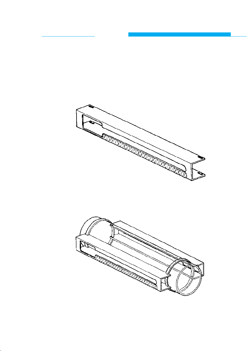
Mounting Procedure:
a Severe rust or thick coatings have to be removed from
the pipe where the transducers will be installed.
b Slide the securing straps through the slots on both
ends of each mounting rail (see fig. C.1).
Fig. C.1 : Mounting rail
c Attach the rails on opposite sides of the pipe such that
the large slots point in opposite directions (see fig. C.2).
Fig. C.2 : Mounting rails fitted on the pipe
22
ALTOSONIC
Operation
UFM 600 T
Page 24
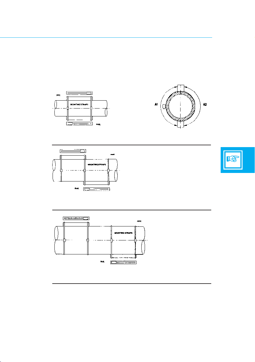
d Use the supplied tape measure to ensure that the rails
are fitted diametrically opposite each other
(see fig. C.3-1a. ).
Distance A1 must equal distance A2. Secure the rails by
tightening the straps.
Fig. C.3 : Mounting positions
23
1.
3.
1a.
Mounting position if calculated transducer distance does
not exceed 350 mm (14")
Mounting position if calculated transducer distance is
between 350 mm (14") and 700 mm (28")
2.
Mounting position if calculated transducer distance does
exceed ≥ 700 mm (28")
Page 25
C.1.2 Programming the application parameters
After the flowmeter has been switched on it will start in the
measuring mode.
Pressing twice the key enters the Start Up Menu.
In this menu the application related parameters can be programmed.
All functions are described in section C.2.
Push Button Functions
The flowmeter can be programmed by means of the three
keys located below the liquid crystal display.
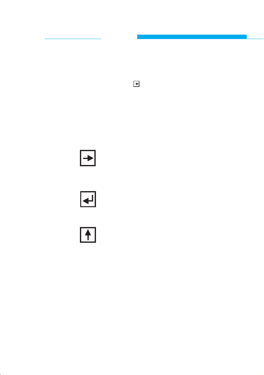
By pushing the left-hand key 'ARROW RIGHT' the
parameter shown on the display will be activated
and the desired value can be entered or an option
can be selected.
After pushing the key in the middle 'ENTER' the
programmed information will be stored and the
program advances to the next parameter.
For entering numbers or letters the 'ARROW UP'
key must be used; this will increment the ASCII
value of the blinking character (next higher number or next letter in the alphabet).
If a selection from a table must be made the
'ARROW UP' key can be used to display the next
option in the table. After using the 'ARROW UP'
key without actually programming a parameter the
next parameter will be displayed.
24
ALTOSONIC
Operation
UFM 600 T
Page 26

Input of values
Input of values outside the range, indicated at the function
descriptions, will result in a flashing error message; the minimum or maximum value allowed is displayed above the error
message.
After pressing any key the function is active again and the
correct value can be entered.
Start Up Menu
Enter all application parameters in the Start Up Menu; see
section C.2 for full details. Continue until the transducer distance is on display. Now the transducers can be installed.
25
Page 27
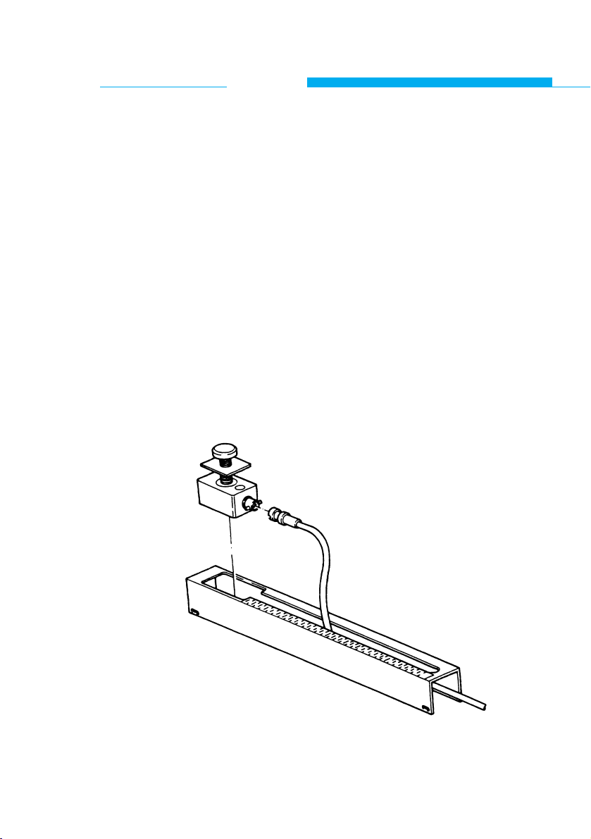
C.1.3 Installation of the transducers
Since the required transducer distance "S" is known now the
transducers can be positioned in the rails:
1 Turn the transducer securing screw completely counter
clockwise until the transducer positioning plate touches
the top of the transducer housing.
2 Feed the coax cables through both mounting rails.
3 Cover the bottom of both transducers with a thick layer of
the sonic coupling grease.
4 Connect each transducer to a coax cable and slide the
transducers into the rails (fig. C.4.) While inserting the
transducers, care must be taken not to touch the pipe
wall with the transducers before the proper position is
obtained, otherwise the coupling grease will be wiped off
the transducers and the result will be a bad sonic coupling between the transducers and the pipe wall.
Fig. C.4 : Position of transducer and cable
26
ALTOSONIC
Operation
UFM 600 T
Page 28

27
NOTE: - The cable connections at the transducers must always
point away from each other (fig. C.5).
- Make sure that the transducers are not placed over a
welding seam.
Fig. C.5 : Upstream and downstream connection
5 Use the cm scale on the mounting rails to position
the transducers at the proper distance from each other
and hand tighten the securing screws.
6 Check using the indication of the low signal marker (see
C 3.1) whether the unit is functioning properly.
Continue with Zero Set function (C.1.4.)
NOTE: REMOVAL OF THE TRANSDUCERS FROM
PIPE WALL
When removing the transducers from the pipe wall, especially
after they have been in place for a long period, care should
be taken:
• Not to damage the tranducers by pulling strongly at the
securing screw.
• Therefore, to remove a tranducer, it must be removed in
a slicing motion. Do not just pull it straight off the pipe all !!
sensor distance S
FLOWDIRECTION
Page 29

C.1.4 Zero set / Zero point calibration
Zero Set
After leaving the transducer distance function the ZERO SET
function can be activated.
The flowmeter is functioning now without displaying any flow
readings. Only the low signal marker (see C.3.1) gives an
indication of the signal quality based on the factory set
default zero point calibration.
The low signal marker will indicate if a zero point calibration is
feasible.
A zero point calibration is strongly advised as this will
improve the overall accuracy.
If no zero point calibration is to be executed, this function
can be skipped.
See also section C.3, Error Detection, for the accuracy to be
expected.
28
ALTOSONIC
Operation
UFM 600 T
Page 30

Zero Point Calibration
Before performing the zero point calibration ensure that:
- The unit is functioning properly (see low signal marker).
- There is no flow at the location where the transducers are
installed and the pipe section is completely filled with liquid.
Now activate the Start Up Menu and enter the ZERO SET
function:
- With DEFAULT or MEASURED will be visible
- Use to select between DEFAULT or MEASURED
- If DEFAULT is selected press to set the preprogrammed
DEFAULT zero point
- If MEASURED is selected press
- Now CALIB. NO will be visible.
- Use to select YES and press
- The microprocessor now performs an input signal test.
- On the top line the zero point correction in % is displayed.
- If the correction is near 0% the calibration was successful;
select STORE YES and press to save the zero point calibration.
If no reliable signal is detected the error message BAD ZERO
is displayed and the calibration should be abandoned; in
order to restart the zero point calibration procedure. The data
collection can be started now or other parameters can be
entered through the programming mode (chapter D).
NOTE: MEASURED zero point is selected if there is no flow.
DEFAULT zero point should be selected if the flow cannot
been stopped.
29
Page 31

C.2 Start Up Menu
C.2.1 Enter start up menu
The Start Up Menu is activated by pressing the key twice
from the measuring mode or pressing the key once from
the main menu 1.0.0.
C.2.2 Application Functions
The functions in which the application parameters can be
programmed always appear on the display in the same order
as described below:
To enter a next function, the key must be pressed.
DIAMETER
Program the outer pipe diameter.
The diameter can be entered either in mm or in inches.
Range:
2.0000 E 0 mm ≤ DIAMETER ≤ 4.0000 E 3 mm
7.8740 E-2 inch ≤ DIAMETER ≤ 1.5748 E 2 inch
PIPEWALL
Program the pipe wall thickness.
The wall thickness can be entered either in mm or in inches.
Range:
1.0000 E-1 mm ≤ PIPEWALL ≤ 5.0000 E 1 mm
3.9370 E-3 inch ≤ PIPEWALL ≤ 1.9685 E 0 inch
30
ALTOSONIC
Operation
UFM 600 T
Page 32

PIPE MAT.
Program the sonic velocity of the pipe material.
The following 5 options are preprogrammed (or will reappear
after running 3.5.8 DEFAULT SET, see chapter D):
STEEL : 3.1700 E 3 m/s
ST. STEEL : 3.1200 E 3 m/s
IRON : 2.1200 E 3 m/s
PVC : 2.1200 E 3 m/s
Other : 1.5000 E 3 m/s
All five option positions can be reprogrammed completely
according to the user´s requirements (names and sonic
velocities).
The sonic velocity can only be programmed in m/s.
Range:
1.5000 E 3 m/s ≤ Sonic velocity ≤ 4.7500 E 3 m/s
See appendix 1 for sonic velocities of the most frequently
used pipe materials.
LINING
Select YES or NO depending on whether or not the pipe is
provided with a lining.
When NO is selected the parameters LINING THICKNESS
and LINING MATERIAL can not be programmed.
LINING TH.
(does not appear on display when lining = "NO" )
The lining thickness can be entered either in mm or in inches.
Range:
1.0000 E-1 mm ≤ LINING THICKNESS ≤ 5.0000 E 1 mm
3.9370 E-3 inch ≤ LINING THICKNESS ≤ 1.9685 E 0 inch
31
Page 33

LINING MAT.
(does not appear on display when lining = "NO")
Program the sonic velocity of the lining material.
The following 5 options are preprogrammed (or will reappear
after running 3.5.8 DEFAULT SET, see chapter D):
PVC : 2.1200 E 3 m/s
Other 1 : 1.0000 E 3 m/s
Other 2 : 1.0000 E 3 m/s
Other 3 : 1.0000 E 3 m/s
Other 4 : 1.0000 E 3 m/s
The sonic velocity can only be programmed in m/s.
Range:
3.0000 E 2 m/s ≤ Sonic velocity ≤ 4.7500 E 3 m/s
See appendix 1 for sonic velocities of some lining materials
used frequently.
All five option positions can be reprogrammed completely
according to the user's requirements (names and sonic
velocities).
LIQUID
Program the sonic velocity of the liquid inside the pipe.
The following 5 options are preprogrammed (or will reappear
after running 3.5.8 DEFAULT SET, see chapter D):
WATER : 1.5000 E 3 m/s
Other 1 : 1.0000 E 3 m/s
Other 2 : 1.0000 E 3 m/s
Other 3 : 1.0000 E 3 m/s
Other 4 : 1.0000 E 3 m/s
The sonic velocity can only be programmed in m/s.
Range:
1.0000 E 2 m/s ≤ Sonic velocity ≤ 2.5000 E 3 m/s
See appendix 2 for sonic velocities of frequently encountered
liquids.
All five option positions can be reprogrammed completely
32
ALTOSONIC
Operation
UFM 600 T
Page 34

according to the user´s requirements (names and sonic
velocities).
NOTE: If the sonic velocity is not known it can be estimated by using
the sonic velocity calculation, see appendix 3.
FULL SCALE
Select the flow rate units and program the full scale value.
A selection can be made out of 9 preprogrammed units and
one unit can be specified by the user (see function 3.5.3,
3.5.4 and 3.5.5 in chapter D).
Unit Range
m3/Sec 9.4240 E-7 ≤ F.S. ≤ 1.5080 E 2
m3/min 5.6533 E-7 ≤ F.S. ≤ 9.0481 E 3
m3/hr 3.3926 E-3 ≤ F.S. ≤ 5.4288 E 5
Liter/Sec 9.4240 E-4 ≤ F.S. ≤ 1.5080 E 5
Liter/min 5.6544 E-2 ≤ F.S. ≤ 9.0481 E 6
Liter/hr 3.3926 E 0 ≤ F.S. ≤ 5.4288 E 8
US G/Sec 2.4896 E-4 ≤ F.S. ≤ 3.9837 E 4
US G/min 1.4937 E-2 ≤ F.S. ≤ 2.3902 E 6
US G/hr 8.9624 E-1 ≤ F.S. ≤ 1.4341 E 8
...../...... 9.4240 E-7 ≤ F.S. ≤ 1.5080 E 2
(user defined unit)
LOCATION
The name of a measuring site or tag number can be programmed here. When function 3.6.5 is activated (see chapter
D) the location name will be recorded in the header of each
data block that is stored.
SENS. DIST.
After the previous parameters in the Start Up Menu have
been programmed, the microprocessor will calculate, either
in mm or inches as chosen for under diameter, the desired
distance between the two transducers, measured along the
pipe axis. Enter this function to read the result on the display.
33
Page 35

ZERO SET :
Zero point calibration.
Select between the factory set default value for the zero point
or perform a zero point calibration for the actual situation.
See paragraph C.1.4 for the precise conditions and instructions for a calibration.
C.2.3 Plausibility check
After any changes are made to the parameter settings the
microprocessor will perform a plausibility check on the
changed settings, before the measuring mode can be activated. If no "impossibilities" in the configuration are detected
the microprocessor asks for confirmation before the new settings are stored.
If discrepancies in the parameters entered are found the
microprocessor will display the message "PARAMERROR"
which prevents you from storing parameters that are incorrect; the options available to correct the configuration are
described in section D.6.
The next function which will appear is again, the first function
of this Start Up Menu: "DIAMETER".
The Start Up Menu is left by pressing the key once from
any function name in the Start Up Menu. When doing this,
the Main Menu will be entered (function 1.0.0.)
34
ALTOSONIC
Operation
UFM 600 T
Page 36

C.3 Error Detection
C.3.1 Low signal marker function
The condition of the input signal from the transducers is indicated by a marker in the top left hand corner of the display.
The marker consists of four arrows divided over 360 degrees.
The microprocessor calculates the percentage of the
measurements that is inconsistent.
Marker indications:
> 80 % of measurements inconsistent
The flowmeter will
not function.
40 % of measurements inconsistent
20 % of measurements inconsistent
The flowmeter will
function, though
not optimally.
10 % of measurements inconsistent
No inconsistent readings detected Optimal functioning
flowmeter.
35
▲
▲
▲
▲
▲
▲
▲
▲
▲
▲
.
.
.
.
.
.
.
.
.
.
Page 37

C.3.2 Error messages
If the microprocessor produces an error message a * sign
appears at the lower left hand side of the display.
Enter the QUIT / RESET mode to view the error message(s)
(see chapter C.5).
It depends on the settings of the Installation functions 3.2.4
and 3.2.6, whether the error messages will be displayed in
between the flow data.
List of Error Messages:
SIGN LOST : Transducer disconnected
TOTALIZER : Overflow of the totalizer.
FREQ.OUTP. F: Overflow of the frequency signal; full
scale value is too small
CUR. OUTP. I : Overflow of the current signal; full
scale value is too small
CAL. DATA : The transducer calibration is
distorted; contact your supplier
EE1 EE2 : Error detected during memory check;
switch unit off and on; if message still
reappears after two attempts, contact
your supplier
EEPROM2 : See EE1 EE2
ROM : Checksum error detected during
memory test; contact your supplier
RAM : Error detected during verification of
parameter settings stored previously;
use function 3.5.8 DEFAULT SET and
switch off and on; if message
reappears contact your supplier.
36
ALTOSONIC
Operation
UFM 600 T
Page 38

37
STORE: A total number of 350 data blocks are
been stored. Rest capacity 40 data
blocks till data storage is full.
FATAL ERROR: Check sum error detected; contact
your supplier.
PARAMERROR: This message will not appear during
measurement; at the end of both the
start up menu and the programming
mode a parameter check is performed before the measuring mode
can be entered (see section D.6).
Page 39

C.4 Data Collection
C.4.1 Data collection procedure
Sampling Rate / Data Storage Capacity
A total number of 390 data blocks can be stored.
This number is independent of the amount of information that
is programmed to be on display and/or stored.
It is very important to determine a useful combination of the
measuring period and the data sampling rate.
If the flow rate shows only minor fluctuations or fluctuations
are not relevant a low sampling rate can be programmed.
Thus a long measuring period can be achieved or more than
one data collecting interval can be realized before the data
has to be transferred to a PC.
If the flow rate fluctuations are important the sampling rate
should not be too low. Otherwise, relevant information might
not be recorded.
NOTE: When all 390 data blocks are occupied no further data will be
stored. The flowmeter will continue to operate normally.
WARNING IS GIVEN WHEN THE DATA STORAGE IS FILLED
WITH 350 DATA BLOCKS (See chapter C.3.2. Error
Messages)
Reset Data
If a new measurement series is started (previous flow data
can be discarded) the data blocks can be cleared; two
RESET DATA functions are available:
1 use the function 3.6.6, RESET DATA, in the programming
mode
2 enter the QUIT/RESET menu (see section C.5.)from the
measuring mode and select the RESET DATA option.
Reset Totalizers
If applicable the totalizers must be reset at the beginning of a
measuring series. Enter the QUIT/RESET menu from the
measuring mode and select the totalizer(s) that have to be
reset (see section C.5)
38
ALTOSONIC
Operation
UFM 600 T
Page 40

Preparation for new measurements
Providing any previous flow data can be discarded, a data
collection session can be started as follows:
1 Select the STORE or BOTH option of function 3.6.3 in the
programming mode
2 Clear the RAM by means of one of the two ways to Reset
Data
3 Start the measuring mode
4 If applicable reset the totalizers
Preparations for continued measurements
It is advisable not to activate the STORE option of function
3.6.3 in the programming mode until the actual measuring
period is to be started; otherwise unnecessary data blocks
are being stored and storage space is lost.
After installing the transducers it is advisable to run in the
measuring mode for some time during which the data is only
sent to the display (function 3.6.3 OFF).
The readings can be checked and adjustments made (e.g.
adjust full scale value) to ensure that the suitable data is collected.
The actual measuring period with data storage (and the RAM
partially filled) can then be started as follows:
1 Select the STORE or BOTH option of function 3.6.3 in the
programming mode
2 Leave the programming mode and enter the measuring
mode via the DIAMETER prompt of the Start Up menu
3 If applicable, reset the totalizers
39
Page 41

C.4.2 Transfer to PC (data and parameters)
Software
The floppy disk provided contains programs for the transfer
and conversion of the measuring data:
- GETFLOW.EXE
Function : Transfer measuring data and/or
parameter settings to the PC
The information will be stored in ASCII
format.
Syntax : GETFLOW <com> <file>
<com> : the number of the serial
port on the PC.
<file> : file name for the data to
be stored.
- FLOW2CEL.EXE
Function : Convert the ASCII data for processing
by Harvard Graphics, VP Planner or
Lotus 1,2,3.
Syntax : FLOW2CEL <input file> <output file>
<Language>
WITH Language:
E = English
D = Deutsch
F = Francais
N = Nederlands
NOTE: Both programs show their syntax if they are run without or
with false extensions.
- README _ E.DOC
If applicable this file offers an update on the software information.
40
ALTOSONIC
Operation
UFM 600 T
Page 42

Data transfer
For the transfer of information from the flowmeter to the PC
proceed as follows:
- Connect the RS 232 cable to the flowmeter and the serial
in/output port of the PC (com1 or com2).
- Enter the programming mode of the flowmeter and
activate the function 3.6.1 or 3.6.2 for either the output of
the parameter settings or the measuring data; see that
the selection is on YES
- Run program GETFLOW on the PC
For example if the Com1 port is connected and the data
has to be stored in file FLOW.DAT then type:
GETFLOW 1 FLOW.DAT
The message WAITING FOR DATA will appear.
- Now press on the flowmeter within 3 seconds.
- The data is transmitted to the PC and stored in the file
indicated using the ASCII format.
Data conversion
After all flow information is stored in an ASCII file use program FLOW2CEL to convert the data to a format that can be
adapted for presentation purposes.
Run program FLOW2CEL on the PC and follow the instructions displayed.
See README _ E.DOC for any additional information.
C.4.3 Terminal programs
Standard terminal programs (e.g. MS Windows® terminal)
can be used to receive data from the UFC 600 T signal
converter by using a straight RS 232 cable with 25 pins
female D-connector.
Settings must be: BAUDRATE 2400
DATA BITS 7
STOP BITS 1
PARITY NONE
41
Page 43

C.5 Quit / Reset Menu
The measuring mode can be exited with the code as
described below to enter the Quit/Reset Menu.
In this menu two functions can be used:
ERRORLIST:
Show the list of errors indicated by the * sign at the left-hand
side of the display.
When the error messages are not programmed to appear on
a regular display (function 3.2.4 and 3.6.4) the only way to
recognize an error (apart from the low signal marker) is by the
* sign at the left-hand side of the display.
Enter the error list with the key; the number of errors and
the first error message will be visible. Use the key to display the other error(s); eventually the ERR.ACQUIT function
will appear.
ERR.ACQUIT function:
After curing the cause of the error(s) enter the ERR.ACQUIT
function by using the key and select YES with key to
reset the error message and error marker *.
Even if the cause of an error is cured the error message and
the error marker will not disappear until they are cleared by
the ERR.ACQUIT function.
Use the key to leave the function.
Use the key to return to the measuring mode.
* Note that these error messages differ from those included
in the data block that is stored and sent to the RS 232
output at regular intervals (function 3.2.4 and 3.6.4) :
at the end of the next complete data collection interval
following the elimination of the errors these messages will
have disappeared automatically.
42
ALTOSONIC
Operation
UFM 600 T
Page 44

RESET:
In this submenu three reset options are available:
TOTAL + : Reset + totalizer.
TOTAL - : Reset - totalizer.
RESET DATA : Reset all data blocks.
In each option YES or NO must be selected.
The reset option is to be used to obtain a clear start of a data
sampling session.
Use the key to return to the measuring mode.
CODE:
The code to exit the measuring mode and to enter the
Quit/Reset mode is:
Although the code is rather simple it prevents the collected
data from being wiped out unintentionally.
If within 3 or 4 seconds the proper code has not been
entered the measuring mode is resumed without having been
interrupted.
43
Page 45

C.6 Direct Output Ports (Analog (mA) output and frequency /
pulse output)
C.6.1 General
The options available for these direct output ports are described further in section D.4 main menu: 3.0.0 INSTALLATION.
Refer to the technical specifications if any equipment is to be
connected to the current and/or frequency output. (see
C.6.3, C.6.4 and chapter F)
C.6.2 Output hold
It is advisable to activate the output hold function (3.5.2)
when the flowmeter is being used as part of a control loop.
NOTE: This hold function also affects the outputs in case of mal-
function (signal lost).
C.6.3 Current output
Specification:
Range : 0 to 20 mA, or 4 to 20 mA or I
0% to...;I 100% programmable
Load : 14 [V]
RL[kohms] <
I 100% [mA]
(e.g. 0.7 kohms at 20 mA,
2.8 kohms at 5 mA).
C.6.4 Frequency output
Specification:
Pulse rate for Q=100%: 10 to 36 000 000 pulses per hour
0.167 to 600 000 pulses per
minute
0.0028 to 10 000 pulses per
second (=Hz)
optionally in pulses per liter, m3or
US gallons
44
ALTOSONIC
Operation
UFM 600 T
Page 46

Active output short-circuit-proof
Terminals 4.1/4.2 : for electromechanical (EMC) or
electronic (EC) totalizers
Terminals 4/4.1/4.2: for electronic (EC) totalizers
Amplitude : approx. 27 V
Load rating see Table "pulse width"
Passive output
Terminals 4/4.1 : open collector for connection of
active electronic totalizers (EC)
or switchgear
Input voltage : 5 to 30 V
Load current : max. 100 mA
Pulse width is automatically choosen, depending on actual out
frequency.
Frequency f at Q=100% Pulse width Load rating of active output
Load current Load
0.0028 Hz < f ≤ 1 Hz 500 ms ≤ 150 mA ≥ 180 Ohm
approx.
50% duty
1 Hz < f ≤ 10 Hz cycle (1:1) ≤ 25 mA ≥ 1 k Ohm
50% duty
10 Hz < f≤ 1000 Hz cycle (1:1) ≤ 25 mA ≥ 1 k Ohm
1000 Hz < f≤ 2547 Hz 160 µs ≤ 25 mA ≥ 1 k Ohm
2547 Hz < f≤10000 Hz 50 µs ≤ 25 mA ≥ 1 k Ohm
45
Page 47

C.6.5 Connection Diagrams
45a
ALTOSONIC
Operation
UFM 600 T
I:
(term.5/6)
F
actie:
EC (term.4/4.1/4.2)
F
passive
EC (term.4/4.1)
F
active
EMC/EC(term.4.1/4.2)
4 4.1
4.2
5+6
-
40V4.1
4.2
27V
5+6
-
EMZ
EZ
40V4.1
4.2
27V
5+6
-
4 4.1
4.2
5+6
-
EZ
EZ
R1
R2
U: 5-30V
I
max
: 100mA
I
U
Page 48

45b
Page 49

C.7 Trouble Shooting
1 The flowmeter does not respond after connection to
the main power supply (no display or output messages).
- Check fuse.
2 The error marker * appears on the display
- Leave the measuring mode and enter the Quit/Reset
menu
(press ; see section C.5).
Cure the cause if necessary, and select
ERR.ACQUIT to reset the error marker.
3 Low signal marker: 3 or 4 markers on.
Cause Solution
Incorrect transducer Reposition transducers (see sec-
tion position C.1.3) using sufficient
coupling grease and check the
transducer distance afterwards.
Poor sonic coupling Check the pipe wall surface;
between pipewall and remove any rust, dirt and/or thick
transducer surface layers of paint or coating.
Apply sufficient grease on the
transducers and make sure not to
wipe off any grease from the transducers while they are being reinstalled.
Pipe is not completely Fill the pipe completely or select a
filled pipe section that is always com-
pletely filled with liquid.
Broken signal cable Use a multimeter to check the
condition of the cables and the
connectors. See your supplier for
46
ALTOSONIC
Operation
UFM 600 T
Page 50

replacements. If 3 or 4 markers
remain the selection of a different location on the pipe wall is recommended; some irregularities at
the interior of the pipe might have
caused poor signal reception.
5 Low signal marker: 1 or 2 markers on.
Cause Solution
Small deviation of the Adjust one transducer approx.
transducer distance from ± 5 mm. until the markers disthe correct value appear; do this very carefully so as
not to disturb the sonic coupling
grease layer between the transducer and the pipe wall.
47
Page 51

D.1 General
In the main menu, two Sub Menus can be activated:
Sub Menu 2 "TEST":
Four function tests can be executed:
- Display test
- Microprocessor test
- Current output test
- Frequency output test
Sub Menu 3"INSTALLATION":
Enter all parameters that determine the initial settings of the
flowmeter and the way the data is processed.
All functions available in both of these menus are listed in
section D.3 and described further in sections D.4 and D.5.
48
ALTOSONIC
Programming mode
UFM 600 T
Page 52

D.2 How to Program
Push button functions:
move the menu pointer one step to the right to
activate the submenu displayed.
either move the menu pointer to the left to leave a
submenu or store entered data and leave the submenu.
will increment the ASCII value of the blinking character by one; either the next higher number or the
next letter in the alphabet. Pushing this button in
the measuring mode, the display will be illuminated
for one hour.
Entering the Start Up Menu:
The Start Up Menu is entered by pressing twice the key
from the measuring mode or from the main menu 1.0.0. by
pressing the key once. The Start Up Menu is left by pressing the key (once to return to main menu 1.0.0, four to
return to measuring mode)
Entering the main menu:
The main menu mode is entered from measuring mode or
the Start Up Menu:
From measuring mode press to enter the main menu.
From Start Up Menu press to enter the main menu.
49
Page 53

Menu selection:
By entering the main menu, the submenu Start Up 1.0.0. will
be on display; use the key to select the submenus TEST
2.0.0. or INSTALL 3.0.0.
If the Start Up Menu is to be selected, press key when
1.0.0. is displayed.
Function selection:
Use the key to select a function from the chosen submenu.
Activate the selected function by pressing the key.
Enter numbers, characters and select units:
If applicable within a function, numbers, characters or units
can be selected at the position which shows a blinking sign
by using the key.
This position is selected by using the key.
The set up of the function is completed by pressing ; the
data is stored and the menu pointer returns to the active
submenu.
Leave Submenu:
Press to return to the main menu.
Ending the programming session:
Ending a programming session can be done by pressing
3 times while one of the submenus (1.0.0, 2.0.0 or 3.0.0.) is
active.
The programmed parameters will be saved directly without a
request whether the changes should be set.
After saving the parameters the microprocessor will go
directly to the measuring mode.
50
ALTOSONIC
Programming mode
UFM 600 T
Page 54

If any discrepancies are detected the error message
PARAMERROR is displayed and a separate menu is activated in which the parameters concerned can be corrected (see
section D.6).
NOTE: To save the programmed parameters in the Start Up menu
(fct. 1.0.0) press three times.
The signal converter is equipped with magnetic sensors (hall
contacts). This allows setting of the signal converter by
means of a hand-held bar magnet. Function of sensors without removing the front cover is the same as the corresponding keys.
Hold the bar magnet by the black rubber cap. Apply blue
end of the magnet (north pole) to the glass pane above the
magnetic sensors.
51
Page 55

D.3 List of Functions
2.00 TEST
2.1.0 DISPLAY
2.1.1 DISP.TEST
2.2.0 PROCESSOR
2.2.1 8048 TEST
2.3.0 CURR. OUTP.
2.3.1 TEST I
2.4.0 FREQ. OUTP.
2.4.1 TEST F
3.0.0 INSTALLATION
3.1.0 FLOW DATA (Submenu) Set flow parameters.
3.1.1 PRIM. CORR.(Function)
3.1.2 TRAN. RANGE
3.1.3 LF. CUTOFF
3.1.4 CUTOFF ON
3.1.5 CUTOFF OFF
3.2.0 DISPLAY Set output functions,
3.2.1 DISP.FLOW L.C.Display and define the
3.2.2 DISP.TOTAL contents of the data
3.2.3 UNIT TOTAL blocks.
3.2.4 ERROR MSG.
3.2.5 DISP TRAN. T.
3.2.6 CYCL. DISP.
3.3.0 CURR. OUTP. Set up analog output.
3.3.1 FUNCTION I
3.3.2 I 0 PCT.
3.3.3 I 100 PCT.
3.3.4 I MAX.
3.3.5 T- CONST I
52
ALTOSONIC
Programming mode
UFM 600 T
Page 56

3.4.0 FREQ OUTP. Set up frequency/pulse output.
3.4.1 FUNCTION F
3.4.2 PULSOUTP.
3.4.3 PULSRATE PULS/UNIT
3.4.4 T- CONST. F
3.5.0 SPEC. FCT. Set special functions.
3.5.1 LANGUAGE
3.5.2 OUTP. HOLD
3.5.3 UNIT TEXT
3.5.4 FACT. QUANT.
3.5.5 FACT. TIME
3.5.6 SET DATE
3.5.7 SET TIME
3.5.8 DEF.SET
3.5.9 SOFTW.V - NR.
3.6.0 COMM.DATA Set Store/RS 232 output.
3.6.1 OUTP. PARAM
3.6.2 OUTP. DATA
3.6.3 SEL. COMM.
3.6.4 INTERVAL
3.6.5 LOCAT.
3.6.6 RESET DATA
NOTE: The function names used in the description of the functions
are presented in the same way as on the L.C. display.
53
Page 57

D.4 Sub Menu: 3.0.0 INSTALLATION
3.1.0 FLOW DATA : set flow parameters
3.1.1 PRIM. CORR. : Primary Correction
This function allows the user to correct the primary constant
that is calculated by the microprocessor. Corrections on the
primary constant are useful in the case of for example poor
installation conditions or comparison to a reference flowmeter.
The primary constant will be multiplied by the number displayed; 1.0000 E0 means no correction and 1.1000 E0 indicates a correction of + 10%.
Range: 0.0000 E0 ≤ Prim. Corr.≤ 2.0000 E0
3.1.2 TRAN. RANGE : Transit (time) Range
Use this function only if the transit time of the acoustic signal
(the time elapsed between transmission and reception) is
used as output on either the current or the frequency output
(see Fct. 3.3.1 and 3.4.1).
The transit time value that corresponds to 100% output is
programmed.
Range: 2.0000 E1 ≤ Tran. Range ≤ 1.0000 E5 µsec
Current output example:
If 200 µsec is entered and the 0 - 20 mA output is being
used then an actual transit time of 150 µsec provides a 15
mA output signal. Likewise, if a 4 - 20 mA output is being
used, a 16 mA signal would be the analog output.
Frequency output example:
If 200 µsec is entered and the pulse rate at full flow is programmed to be 10000 Hz then an actual transit time of
120 µsec is indicated by a 6000 Hz signal.
54
ALTOSONIC
Programming mode
UFM 600 T
Page 58

3.1.3 L.F. CUTOFF : Low Flow Cutoff
To avoid erroneous measurements at low flow rates the Low
Flow Cutoff can be used ( see Fig. D.2).
Fig. D.2 : Low flow cutoff
If the flow rate drops below the "Cutoff On" level all outputs
will be switched off and if the flow rate exceeds the"Cutoff
Off" level the outputs will be activated again.
The "Cutoff On" level must be lower than the "Cutoff Off"
level otherwise a PARAMERROR message appears at the
parameter check (see section D.6).
After entering the function either YES or NO can be selected.
If YES is selected functions 3.1.4 and 3.1.5 become active.
If NO is chosen the low flow cutoff becomes inactive and
functions 3.1.4 and 3.1.5 will not appear on the display.
55
ACTUAL
FLOW
FLOW
METER
OUTPUT
OUTPUT INACTIVE
(flow=0%)
TIME
CUTOFF OFF LEVEL
CUTOFF ON LEVEL
TIME
Page 59

3.1.4 CUTOFF ON : (only if at 3.1.3 YES was
entered)
Program the flow rate level below which all outputs will be
switched off.
Enter the value in % of the full scale.
Range: 1- 20
NOTE: This value must be lower than the Cutoff Off value !!
3.1.5 CUTOFF OFF : (only if at 3.1.3 YES was
entered)
Program the flow rate level at which all outputs become
active again.
Enter value in % of full scale.
Range: 1- 20
56
ALTOSONIC
Programming mode
UFM 600 T
Page 60

3.2.0 DISPLAY : set output functions
L.C.display
NOTE: All functions that are programmed to be on display can also
be saved as programmed in function 3.6.3 SEL.COMM.
3.2.1 DISP. FLOW : Display Flow rate
Determine whether the flow rate should be displayed and if
so, in what sort of units; select a display option using the
key and press to store:
NO DISPLAY :
m3/Sec :
m3/min :
m3/hr :
Liter/Sec :
Liter/min :
Liter/hr :
US G/Sec : U.S. Gallon per second
US G/min :
US G/hr :
——-/—- : reserved for user defined unit
PERCENT : percentage of full scale as entered
in Start Up menu
3.2.2 DISP. TOTAL : Display Totalisator
outputs
Select which totalizer outputs should be displayed by using
the key and press to store:
NO DISPLAY : (function 3.2.3 will not appear)
+ TOTAL : Totalizer for positive flow
- TOTAL : Totalizer for negative flow
+/- TOTAL : Totalizers for both positive and
negative flow
SUM TOTAL : [+ TOTAL]- [- TOTAL]
ALL TOTAL : All three totalizer options are active
57
Page 61

3.2.3 UNIT TOTAL : unit for totalizers
(only if a totalizer has been set in 3.2.2)
Select unit for the totalizers using the key and press
to store:
m3 :
Liter :
US G :
------- : User defined unit
3.2.4 ERROR MSG. : Display Error Messages
Determine whether error messages should be displayed and
if so, what type of error messages; select a message option
using the key and press to store:
NO MESSAGE :
US ERROR : Only display of errors
related to the measurement itself
TOT. ERROR : Display of totalizer
errors only
ALL ERROR :
3.2.5 DISP. TRAN. T : Display Transit Time
The transit time is the time lapse between transmission of the
acoustic signal by one transducer and the reception of the
signal by the opposite transducer.
Select display of the transit time; choose either YES or NO
using the key and press to store.
58
ALTOSONIC
Programming mode
UFM 600 T
Page 62

3.2.6 CYCL. DISPL. : Cyclic Display
The cyclic display option can be used to automatically
change the function of the display, if more than one variable
is programmed to be displayed.
Only one variable can be shown on the display at a time.
With this option active the display sequences from one variable to the next every 5 seconds.
If the error messages are programmed to be displayed, these
appear in between the successive variables, if applicable.
For the totalizers and the flow rate, the actual function of the
display is indicated by an arrow symbol at the bottom of
the display.
If NO is selected the successive display of the variables is obtained by using the key.
59
▼
Page 63

3.3.0 CURR. OUTP.I : set up analog current
output
3.3.1 FUNCTION I : Program the analog
current output
Select an output option using the key and press
to store:
2 DIR : Enables flow measurement in 2 direc-
tions(+ and -) without change of
polarity in the output signal (Fig. D.3)
TRAN. TIME : Output signal is proportional to
the measured transit time of the
acoustic signal.
NOTE: this function requires:
- current setting at zero flow, Fct. 3.3.2
- current setting at full flow, Fct. 3.3.3
- transit time at full flow, Fct. 3.1.2
(see example in description of Fct. 3.1.2)
NO SIGNAL : Output signal indicates "signal loss".
OFF : No current output.
F/R IND. I : Output signal as flow direction
indication, 0% at + flow direction
and 100% at -flow direction
(fig. D.4).
1 DIR : Flow measurement in 1 direction
(+) only. (Fig. D.5)
I < I 0 PCT : Allows the output signal to drop
below the programmed value for
0% flow at negative (-) flow
direction. If 10 mA is programmed for
0% flow (Fct.3.3.2) and 20 mA for
100% (Fct. 3.3.3) then the output will
60
ALTOSONIC
Programming mode
UFM 600 T
Page 64

Fig. D.3 : Bi-directional flow (I) Fig. D.4 : Flow direction indication (I)
or signal loss indication (I)
Fig.D.5 : Positive flow (I) Fig. D.6 : Negative flow and output (I)
61
be 0 mA at - 100% flow (fig. D.6)
Signal lost
Signal received
Page 65

3.3.2 [I 0 PCT] : Program current output
at 0 %flow
Range: 00 mA ≤ [I 0 PCT] ≤ 16 mA
NOTE: This value must be lower than the [I 100 PCT] value !!
If this is not the case, a PARAMERROR message will appear
during the parameter check procedure.
3.3.3 [I 100 PCT] : Program current output
at100% flow.
Range: 04 mA ≤ [I 100 PCT] ≤ 20 mA
[I 100 PCT] must exceed [I 0 PCT] by at least 4 mA; if this is
not the case, a PARAMERROR message appears during the
parameter check (see section D.4).
3.3.4 [I MAX] : Program maximum out
put current
The maximum output level can be limited to protect accessory equipment.
Range: 04 mA ≤ I MAX ≤ 22 mA
[I MAX] must be equal to or greater than [I 100 PCT]; if this is
not the case, a PARAMERROR message appears during the
parameter check (see section D.4).
3.3.5 T - CONST.I : Time constant of cur-
rent output
To flatten out sudden fluctuations in the current output signal
a first order filter is included.
Program the time constant for the current output:
Range: 4.0000 E-2 ≤ T - CONST. ≤ 3.6000 E 3
Recommended initial value : 2 to 5 sec.
ATTENTION: Time constant also affects readings on
LC-display.
62
ALTOSONIC
Programming mode
UFM 600 T
Page 66

3.4.0 FREQ. OUTP. F : set up frequency /
pulse output
3.4.1 FUNCTION F : Program the analog fre-
quency output
Select an output option using the key and press
to store:
2 DIR : Enables flow measurement in 2 direc-
tions (fig. D.7).
TRAN. TIME : Output signal is proportional to the
measured transit time of the acoustic
signal.
NOTE: This function requires:
- PULSRATE setting, Fct. 3.4.2
- PULSRATE at full flow, Fct. 3.4.3
- Transit time at full flow, Fct. 3.1.2
(see example in description of Fct. 3.1.2)
NO SIGNAL : Output signal indicates "signal loss".
OFF : No frequency output.
F/R IND. F : Output signal as flow direction indica-
tion, 0% at + flow direction and
100% at - flow direction (Fig. D.8).
1 DIR : Flow measurement in 1 direction (+)
only (Fig. D.9).
Fig. D.7 : Bi-directional flow(F) Fig. D.8: Flow direction indication(F)
63
signal received
signal lost
only (Fig. D.9).
Page 67

Fig.D.9: Positive flow (F)
3.4.2 PULSOUTP. : Frequency output mode
Select one of the two frequency output modes using the
key and press to store:
PULSE/UNIT : Pulses per unit of volu-
me.
PULSRATE : Pulses per unit of time
at full scale flow.
Example of PULSE/UNIT :
Pulse value : 10 pulses per m3 (set
via Fct.3.4.3)
After 60 m3 have passed : Output: 600 pulses
since start.
Example PULSRATE :
Full scale setting : 1000 liters per second
(set via Start Up Menu)
Pulse rate full scale flow : 1000 pulses per second
(set via Fct. 3.4.3)
At 600 liters per second : Output: 600 Hz signal.
64
ALTOSONIC
Programming mode
UFM 600 T
Page 68

or signal lost indication (F)
3.4.3 PULS/UNIT - PULSRATE
(pulse/unit or pulse rate depends on selection in 3.4.2)
PULSE/UNIT : Program number of pul-
ses per unit of volume:
Pulse per volumetric unit: Range (maximum):
PulS/m3 9.9990 E 8
PulS/Liter 9.9990 E 5
PulS/US G 3.7850 E 6
PULSRATE : Program pulses per unit
of time at full scale flow:
Pulse rate unit: Range:
Min. Max.
PulSe/Sec 2.7778 E-3 1.0000 E 4
PulSe/min 1.6667 E-1 6.0000 E 5
PulSe/hr 1.0000 E 1 3.6000 E 7
3.4.4 T - CONST. F : Time constant of fre-
quency output
(see 3.3.5 T- CONST.I)
Program one of the two options for the time constant of the
frequency output:
T<F> = T<I> : Equal to the time con-
stant of the current output (see 3.3.5).
T<F> = 40 msec
65
Page 69

3.5.0 SPEC. FCT. : set special functions
3.5.1 LANGUAGE : Display language
Select a language option using the key and press
to store:
GB/USA : English
D : German
F : French
NL : Dutch
3.5.2 OUTP. HOLD : Hold outputs during
programming
If the flowmeter is not in the measuring mode no flow data is
available and all output levels will normally drop to zero.
With this function active all outputs maintain their last value
before the measuring mode was exited.
This feature should be utilized at the user's discretion.
Caution should be observed, if the signal is used in a control
loop since the controller may have to be switched to "manual". In all cases, responsible personnel should be notified that
the output is on "hold".
Select YES or NO using the key and press to
store.
3.5.3 UNIT TEXT
With this function the name of the user defined unit can be
programmed, e.g. Barrels/day.
The format of the unit is preprogrammed: -------/-----.
With both and keys the text (capital and numbers)
can be programmed. Use to store.
66
ALTOSONIC
Programming mode
UFM 600 T
Page 70

3.5.4 FACT. QUANT.
If a user defined unit is applied the quantity factor has to be
programmed.
This must be the conversion ratio into m3.
In the example with Barrels/Day (see 3.5.3) the quantity unit
Barrel has to be converted into m3 (1 Barrel = 1.5898 E-1
m3).
3.5.5 FACT. TIME
If a user defined unit is applied the time factor has to be programmed.
This must be the conversion ratio into seconds.
In the example with Barrels/Day (see 3.5.3) the time unit Day
has to be converted into seconds (1 Day = 8.6400 E 4 seconds).
3.5.6 SET DATE
Program the correct date in this function.
The actual date is included in the header of each data block
that is stored.
On entering this function the date can be programmed in
(mm-dd-yy) notation.
Programming the actual date is similar to that of numbers.
3.5.7 SET TIME
Program the correct time in this function.
The actual time is included in the header of each data block
that is stored.
Programming is similar to numbers.
67
Page 71

3.5.8 DEFAULT SET
If this function is used all parameters will be reprogrammed
to default settings (see Appendix 5).
(NOTE: factory settings are not affected by this function)
NOTE: The Date, Time and Location data will be lost, too !!
This function should only be used to restart programming if
the cause of a PARAMERROR can not be found; it offers a
start with no error messages as far as the parameters are
concerned.
3.5.9 SOFTW. V. NR.
This function can be entered to view the number of the current software version.
No action can be taken here.
68
ALTOSONIC
Programming mode
UFM 600 T
Page 72

3.6.0 COMM. DATA : set RS 232 output /
store
3.6.1 OUTP. PARAM.
With this function all programmed parameters can be sent to
a PC via the RS 232 output.
NOTE: No error message is given if a communication error (no
RS 232 response) occurs!
Select YES and press to start the output.
3.6.2 OUTP. DATA
With this function all collected data stored in the RAM can be
sent to a PC via the RS 232 output.
NOTE: No error message is given if a communication error (no
RS 232 response) occurs!
Select YES and press to start the output.
3.6.3 SEL. COMM.
With this function the output medium can be selected to
which the data is sent as programmed in 3.2.0 and 3.6.4.;
the intervals are programmed in 3.6.4.
The options are:
OFF : No output at all (only on LCD).
BOTH : Data is stored in the RAM as well as
sent to the RS 232 output.
OUTPUT : Data is send to the RS 232 output
only.
STORE : Data is stored in the RAM only.
For settings of the PC terminal program see: C 4.3.
69
Page 73

3.6.4 INTERVAL (not visible if SEL. COMM is OFF)
Program the interval between successive data collections as
programmed in 3.6.3.
Range: 01 - 60 min
3.6.5 LOCATION : Location
If this function is activated the location, as programmed in the
Start Up Menu, is recorded in the header of each data block
that is stored or sent to RS 232.
Select YES or NO using the key and press to store.
3.6.6 RESET DATA
If STORE is programmed in function 3.6.3 all data blocks are
stored in the internal RAM.
With this function the RAM can be cleared, to be able to store
new data (up to 390 blocks).
NOTE: the parameter settings are not affected by this function.
Select YES or NO using the key and press to store.
70
ALTOSONIC
Programming mode
UFM 600 T
Page 74

71
Page 75

D.5 Sub Menu : 2.0.0 TEST
2.1.0 DISPLAY
2.1.1 DISPLAY TEST
All individual segments of the liquid crystal display are
activated in a sequence ending in a flashing display of all
segments.
No action can be taken.
Select YES and press to start the test.
2.2.0 PROCESSOR
The microprocessor performs a self test.
No action can be taken.
Select YES and press to start the test.
If the test does not end with the message NO ERROR
contact your dealer.
Press to exit the function.
2.3.0 CURR. OUTP. I
2.3.1 TEST
To check the functioning of both the analog output and the
externally connected instruments and wiring, the analog output can be set to 7 specific values:
0, 4, 8, 12, 16, 20 and 22 mA
The value shown on the display should match the indication
on the instrument connected to the current output.
Press to start the test and use the
key to select output current.
Press to exit the function.
72
ALTOSONIC
Programming mode
UFM 600 T
Page 76

2.4.0 FREQ. OUTPUT
2.4.1 TEST
To check the functioning of both the frequency output and
the externally connected instruments and wiring, the frequency output can be set to 5 specific values:
1, 10, 100, 1000 and 10000 Hz
The value shown on the display should match the indication
on the instrument connected to the frequency output.
Press to start the test and use the
key to select output frequency.
Press to exit the function.
73
Page 77

D.6 Parameter errors
If discrepancies in the parameters entered are found the
microprocessor will display the message "PARAMERROR"
thus preventing you from storing parameters that are incorrect.
The PARAMERROR menu can appear at the end of both the
Start Up menu and the Installation Menu.
A third main menu is available now:
Fct. 4.0.0 PARAM.ERROR
In this menu only one submenu is available at a time; only the
submenu that applies to the discrepancy to be corrected will
be displayed.
List of possible submenus and functions within PARAMERROR:
4.0.0 PARAMERROR Discrepancy:
4.1.0 V RANGE The combination of the diameter, wall and lining thickness and the full
scale flow rate is not feasible.
4.1.1 DIAMETER
4.1.2 PIPEWALL
4.1.3 LINING TH.
4.1.4 FULL SCALE
4.2.0 I RANGE [I 100 PCT] does not exceed
[I 0 PCT] by at least 4 mA
4.2.1 I 0 PCT
4.2.2 I 100 PCT
4.3.0 I MAX mA [I MAX] is not equal to or greater
than [I 100 PCT]
4.3.1 I 100 PCT
4.3.2 I MAX
4.4.0 CUTOFF CUTOFF ON exceeds CUTOFF OFF
74
ALTOSONIC
Programming mode
UFM 600 T
Page 78

4.4.1 L.F. CUTOFF
4.4.2 CUTOFF ON
4.4.3 CUTOFF OFF
4.5.0 F>10KHZ Output frequency is too high,
must be less than 10kHz
4.5.1 FULL SCALE
4.5.2 PULSOUTP.
4.5.3 PULSRATE
4.5.4 PULS/UNIT
4.6.0 APPL.DATA Programmed sonic velocities are not
within the specified range
4.6.1 PIPE MAT.
4.6.2 LIQUID
4.6.3 LINING MAT.
4.7.0 FREQ.OUTPUT The combination of F-Function and
Pulsoutput is not feasible
4.7.1 FUNCTION F
4.7.2 PULSOUTP.
Activate the submenus and functions as described in section
D.2.
After the correct parameter values have been entered the
PARAMERROR menu can be exited by pressing the key
7 times; the parameters are checked and saved and the program stops at the beginning of the Start Up menu.
NOTE: Instead of activating the PARAMERROR menu the
INSTALLATION or TEST menus can be entered by using the
key.
75
Page 79

E.1 Mains Fuse
The mains fuse is located in the connection compartment.
NOTE: ONLY USE FUSES AS INDICATED NEXT TO THE FUSE
FITTING TO PREVENT SERIOUS DAMAGE TO THE
ELECTRONIC EQUIPMENT (see Spare Parts).
If the fuse is blown regularly, contact your dealer.
76
ALTOSONIC
Maintenance
UFM 600 T
Page 80

77
Page 81

F.1 General
Measuring beam 1
Diameter range 50 ... ≥ 3000 mm (2” ... ≥120”)
Pipe wall thickness ≤ 40 mm ( ≤ 1.6”)
Pipe wall materials metal, plastics, ceramics,
asbestos-cement with or without
firmly attached linings or coatings
Fluids any clean homogeneous liquid
with a gaseous or solid particle
content ≤1% by volume
Fluid temp. -25 to +120 °C (-13 to 248 °F)
Error limits 1 to 3%, depending on application
Reproducibility up to 0.2%
Time constant 0.04 to 3600 s
Outputs current, frequency/pulse and RS
232 for data transfer to PC
Display for indication of all measuring data,
calculated transducer distance,
error messages and transit time
Measured values volumetric flow rate, total flow,
transit time and flow direction (for-
ward/reverse)
Cable length:
Standard 5 m (15 ft)
Optional > 5 m...≤ 300 m( >15 ft...≤ 900 ft)
78
ALTOSONIC
Technical Data
UFM 600 T
Page 82

F.2 Transducers & Clamp-on Set
Transducers single beam; 2x RS 600
Diameters A single clamp-on set suitable for
50 mm (2”) to 2000 mm (80”)
pipes, incorporating 2 rails with
cm-scale and straps
Materials:
Transducer housing nickel plated brass with plastic
contact surface.
Rails aluminium, anodized
Protection category IP 65 (transducers with BNC connec-(standard): tors) acc. DIN 40050 / IEC 144
(option): IP 68 (cables fix connected to the
transducers)
Ambient temp. -25 to 60 °C
Process liquid temp. -25 to 120 °C
NOTE: High temperature sensor cable optional available.
79
Page 83

F.3 Signal Converter
Version UFC 600 T
Outputs fully programmable
galvanically insulated
- analog 0 to 20 mA, or 4 to 20 mA, or
I[0%] to I[100%] programmable.
load ≤ 100 Ohm
- frequency/pulse
pulse rate 0.0028 Hz.(= 10 pulses/hour) to
10000 Hz. or pulses per liter, m3,
US gallon, or per user defined unit
Low flow cut off programmable
in : 1 to 19%
out: 2 to 20%
80
ALTOSONIC
Technical Data
UFM 600 T
Page 84

Local display: back-lit LCD
Display functions actual flow rate, forward-, reverse-
and sum-totalizers (7 digit), transition time and error messages;
each programmable for continuous or sequential display
Display units
actual flow liters, m3, or US gallons per sec-
ond, minute or hour and one free
programmable unit
totalizers liters, m3, or US gallons and one
freely
programmable unit; min. one year
overflow time
Display language English, French, German, Dutch;
other languages on request
Display arrangement 8 digit , 7 element numerical and
sign display,
1st line symbols for push-button acknow-
ledgement
2nd line 10 character 14 segment text dis-
play.
3rd line 4 markers to identify the actual
display function
functions location, actual flow rate (and
direction), totalizer, time, transittime and error messages
81
Page 85

Power supply
AC power supply: 85 - 264 VAC
DC power supply: 18 - 32 VDC
Power consumption ≤ 10 VA AC
≤ 8 W DC
Housing Cast aluminium
82
ALTOSONIC
Technical Data
UFM 600 T
Page 86

Ambient temp. -25 to +50 °C (-13 to 122°F)
Protection
category IP 65, acc. to IEC 529
(equivalent to NEMA 4x)
Full scale value (Din= inner pipe diameter)
lower limit (V
100% min
. = 0.5 m/s)
Q
100%min
[m3/h] = ( Din [mm]/100 )
2
*
14.2
Q
100%min
[m3/h] = ( Din [inch] )
2
*
0.9
Q
100%min
[USGPM] = ( Din [inch])
2
*
3.9
upper limit
(V
100%max
= 17.1 m/s)
Q
100%max
[m3/h] = (Din [mm] )
2
*
0.05
Q
100%max
[m3/h] = (Din [inch] )
2
*
31.25
Q
100%max
[USGPM] = (Din [inch] )
2
*
138
Reynolds
number Re > 10.000
Repeatability 0.2
R = [%]
V
m*Di
R = repeatability in %
V
m
= flow velocity [m/s]
D
i
= inner pipe diameter [m]
83
Page 87

APPENDIX 1 : Pipe Material Sonic Velocities
ALTOSONIC
Appendix
84
MATERIAL NAME SONIC VELOCITY
Carbon Steel c ≤ 0.3% 3064 m/s
Carbon Steel c > 0.3% 3173 m/s
Carbon-Moly Steel 3173 m/s
Cr-Mo-Steel Cr ≤ 3% 3173 m/s
Cr-Mo-Steel 5% ≤ Cr ≤ 9% 3040 m/s
Chromium Steel (stainless) 3177 m/s
Austenitic St. Steel (general) 3120 m/s
St. Steel 304 3120 m/s
St. Steel 310 3120 m/s
St. Steel 316 3120 m/s
St. Steel 321 3120 m/s
St. Steel 347 3120 m/s
Grey Cast Iron 2125 m/s
Monel 67 Ni- 30 Cu 2810 m/s
Monel 66 Ni- 29 Cu- Al 2823 m/s
Alloy 706 (90 Cu - 10 Ni) 2334 m/s
Alloy 710 (80 Cu - 20 Ni) 2582 m/s
Alloy 715 (70 Cu - 30 Ni) 2513 m/s
Copper Alloys 120 and 122 2149 m/s
Lead-Tin-Bronze alloy 922 A9 1985 m/s
Commercial Brass (65 Cu-35 Zn) 2060 m/s
Aluminium 3269 m/s
Incoloy 800/800H Ni-Fe-Cr 3024 m/s
Inconel 600 Ni-Cr-Fe 3004 m/s
Commercial pure Titanium 2975 m/s
PP 2120 m/s
PVC 2120 m/s
Perspex 2730 m/s
Asbestos Cement 4195 m/s
UFM 600 T
Page 88

APPENDIX 2 : Sonic Velocities of Liquids
85
LIQUID NAME SONIC VELOCITY at 20°C
Acetone 1174 m/s
Benzene 1295 m/s
Carbon Disulphide 1149 m/s
Caster Oil 1477 m/s
Chloroform 987 m/s
Diesel Oil 1250 m/s
Ethanol 1207 m/s
Ethanol Amide 1724 m/s
Ethyl Ether 985 m/s
Ethylene Glycol 1658 m/s
Freon 690 m/s
Glycerol 1904 m/s
Kerosine 1324 m/s
Mercury 1407 m/s
Methanol 1103 m/s
Methylene lodide 980 m/s
Nitrobenzene 1460 m/s
Turpentine 1326 m/s
Water ( 0 - 20
o
C ) 1484 m/s
Water ( 21- 40oC ) 1505 m/s
Water ( 41 - 60oC ) 1529 m/s
Water ( 61 - 80oC ) 1538 m/s
Sea Water 1531 m/s
Xylene Hexafluoride 879 m/s
Page 89

ALTOSONIC
Appendix
86
APPENDIX 3 : Sonic velocity calculation Using Indicated
Transit Time
Start
Measuring
Mode
Check
indicated
transducer
Restart
procedure
Install transducers using
Sonic Velocity of Water 1500
m/s
Look at "Low Signal Marker"
to set the correct Transducer
Distance
Correct the Transit Time (TT)
for delay in the
pipewall to find the
True Transit Time (TTT)
Calculate
Y =
Pipe Inner Diam.
True Transit Time
Calculate
Sonic Vel. = 1054 *Y
Program calculated
Sonic Velocity
See upper left corner of the display
Transit Time should be on display,
see fct. 3.2.5.
For Stainless Steel and (Cast) Iron:
TTT = TT - 0.8 *t - 7.6
For plastics:
TTT = TT - 1.2 * t - 7.6
with:
TTT = True Transit Time in [us]
TT = Indicated Transit Time in [us]
t = Pipe wall Thickness in [mm]
With:
- Pipe Inner Diameter in [mm]
- True Transit Time (TTT) in [us]
With:
- Sonic. Vel. in [m/s]
Read the Transit Time value
indicated in the display
difference
≥ 5 mm
difference
< 5 mm
UFM 600 T
Page 90

APPENDIX 4 : Exponential Notation
Most values have to be entered in the exponential notation as will be
made clear by the message displayed.
Exponential Notation: Y.YYYY E±Z
This indicates that Y.YYYY should have a value between
1.0000 and 9.9999 (1.0000 < Y.YYYY < 9.9999).
The value of Z gives the multiplication factor, e.g.:
Z = +0 indicates Y.YYYY x 1
Z = +1 indicates Y.YYYY x 10
Z = +2 indicates Y.YYYY x 100
Z = +3 indicates Y.YYYY x 1000
etc.
For small values the exponent Z will be negative.
(Press ARROW UP when E is blinking)
Z gives the dividing factor, e.g.:
Z = -1 indicates Y.YYYY / 10
Z = -2 indicates Y.YYYY / 100
Z = -3 indicates Y.YYYY / 1000
etc.
Examples:
program: 1.0345 as 1.0345 E+0
16.167 as 1.6167 E+1
550.12 as 5.5012 E+2
2987.1 as 2.9871 E+3
and with negative exponents:
0.335 as 3.3500 E-1
0.0205 as 2.0500 E-2
0.0015 as 1.5000 E-3
87
Page 91

UFM 600 T
APPENDIX 5 : Default Settings + Example of Output Parameters
The next page shows all parameters after the function Default Set (3.5.8)
has been used. These are the default settings as programmed by the factory.
The way the settings are presented is identical to the RS 232 output after
using function Output Parameters (3.6.1).
ALTOSONIC
Appendix
88
Page 92

1.0.0. STARTUP
DIAMETER
1.0000E+2
mm
PIPE WALL
1.0000E+0
mm
PIPE MAT.
3.1700E+3
LINING
NO
LIQUID
1.5000E+3
WATER
FULL SCALE
1.0000E+2
m
3
/hr
LOCATION
SENS. DIST.
4.4329E+1
mm
ZERO SET.
MEAS. MODE
3.0.0. INSTALL.
3.1.0 FLOW DATA
3.1.1 PRIM. CORR.
1.0000E+0
3.1.2 TRAN. RANGE
3.0000E+2
uSec
3.1.3 L.F. CUTOFF
YES
3.1.4 CUTOFF ON 01%
3.1.5 CUTOFF OFF 02%
3.2.0 DISPLAY
3.2.1 DISP. FLOW
m
3
/hr
3.2.2 DISP. TOTAL.
+ TOT
3.2.3 UNIT TOTAL
m
3
3.2.4 ERROR MSG.
NO MESSAGE
3.2.5 DISP.TRAN.T.
NO
3.2.6 CYCL. DISP.
NO
3.3.0. CURR. OUTPUT
3.3.1 FUNCTION I
1 DIR.
3.3.2 I 0 PCT.
04
mA
3.3.3 I 100 PCT.
20
mA
3.3.4 I MAX mA
22
mA
3.3.5 T-CONST.
4.0000E+0
Sec
3.4.0 FREQ.OUTPUT
3.4.1 FUNCTION F
1 DIR.
3.4.2 PULSOUTP.
PULS/UNIT
3.4.3 PULS/UNIT
1.0000E+0
Puls/m
3
3.4.4 T-CONST.
40 mSec
3.5.0 SPEC. FCT.
3.5.1 LANGUAGE
GB/USA
3.5.2 OUTP. HOLD
NO
3.5.3 UNIT TEXT
––/–
3.5.4 FACT. QUANT.
1.0000E+0
3.5.5 FACT. TIME
1.0000E+0
3.5.6 SET DATE
01-01-90
3.5.7 SET TIME
12:00:00
3.6.3 SEL. COMM.
OFF
3.6.6 RESET DATA
89
Page 93

UFM 600 T
APPENDIX 6 : Spare Parts
Krohne Description Number Type/remarks
ordering per
number UFM 600 T
230262- 01 Mounting Rail 2 UL 600R (with slots)
231266- 01 Cable, coax 1 5 m, BNC-connectors
(coded)
231266- 02 Cable, coax 1 5 m, BNC-connectors
231266- 03 Cable, coax (1) 10 m, BNC-connectors
(coded)
231266- 04 Cable, coax (1) 10 m, BNC-connectors
230271- 02 Transducer 2 UL 600 R
230306- 02 Sonic coupling grease 1 Tube, Blasolube, 70 g
53089001 Tape measure 1 500 cm (192”)
53063201 Small Mounting strap 2 60-215
53063203 Large Mounting strap 4 60-540
231021- 06 Disc 1 UFM 600/ 3 1/2" Disc
50567800 Fuse 1 T zoom A, 20 x 5 mm
85V -264 VAC
50782300 Fuse, main 1 T 1.6 mA, 20 x 5 mm
7.3071831 Manual 1 UFM 600 T
53133301 Cable RS232 1
S 153000364 Ultrasonic wall thickness (1) T-Mike, incl. probes,
gauge AC/DC converter,
couplant gel
NOTE: Numbers between brackets (..) are not part of
standard delivery.
90
ALTOSONIC
Appendix
 Loading...