

Page 1
Handbook
Handbook
UFM 530 HT
UFM 530 HT
UFM 530 HTUFM 530 HT
HandbookHandbook
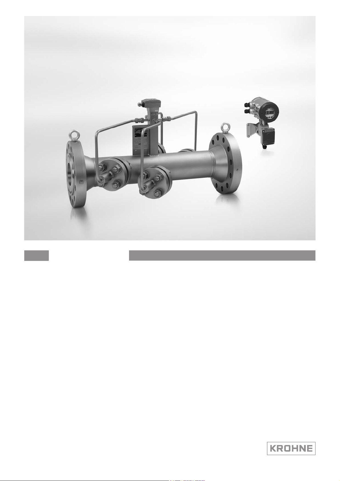
Inline ultrasonic flowmeter for high-temperature liquids
Hardware version: 2134721100-200
Software μP2: 90-05
© KROHNE 12/2013 - 4002393201- HB UFM 530 HT R02 en
Page 2

: IMPRINT :::::::::::::::::::::::::::::::::::::::
All rights reserved. It is prohibited to reproduce this documentation, or any part thereof, without
the prior written authorisation of KROHNE Messtechnik GmbH.
Subject to change without notice.
Copyright 2013 by
KROHNE Messtechnik GmbH - Ludwig-Krohne-Str. 5 - 47058 Duisburg (Germany)
2
www.krohne.com 12/2013 - 4002393201- HB UFM 530 HT R02 en
Page 3

UFM 530 HT
CONTENTS
1 Safety instructions 5
1.1 Software history ............................................................................................................... 5
1.2 Intended use ..................................................................................................................... 5
1.3 Certifications .................................................................................................................... 5
1.3.1 CE-certification .......................................................................................................................5
1.4 Safety instructions from the manufacturer ..................................................................... 6
1.4.1 Copyright and data protection ................................................................................................ 6
1.4.2 Disclaimer ............................................................................................................................... 6
1.4.3 Product liability and warranty ................................................................................................ 7
1.4.4 Information concerning the documentation........................................................................... 7
1.4.5 Warnings and symbols used................................................................................................... 8
1.5 Safety instructions for the operator................................................................................. 8
2 Device description 9
2.1 Scope of delivery............................................................................................................... 9
2.2 Device description .......................................................................................................... 10
2.3 Nameplates .................................................................................................................... 10
2.4 Example nameplate........................................................................................................ 11
3 Installation 12
3.1 General notes on installation ......................................................................................... 12
3.2 Storage ........................................................................................................................... 12
3.3 Transport ........................................................................................................................ 12
3.4 Inlet and outlet ............................................................................................................... 13
3.5 Mounting......................................................................................................................... 14
3.5.1 Mounting position of the flow sensor ................................................................................... 14
3.5.2 Mounting location of the flow sensor ................................................................................... 14
3.5.3 Insulation............................................................................................................................... 17
3.5.4 Pipe flanges........................................................................................................................... 17
3.5.5 Pipes with cathodic protection ............................................................................................. 18
4 Electrical connections 19
4.1 Safety instructions.......................................................................................................... 19
4.2 Power supply of the converter ....................................................................................... 19
4.3 Connection of signal cables ........................................................................................... 21
4.4 Electrical connections of the signal inputs and outputs ............................................... 22
4.4.1 Non Ex versions .................................................................................................................... 22
4.4.2 Ex versions ............................................................................................................................ 25
4.5 Connection diagram examples ...................................................................................... 29
4.5.1 Current output ...................................................................................................................... 29
4.5.2 Pulse output .......................................................................................................................... 30
4.5.3 Digital input........................................................................................................................... 31
4.5.4 Analog input .......................................................................................................................... 32
5 Start-up 33
www.krohne.com12/2013 - 4002393201- HB UFM 530 HT R02 en
3
Page 4

CONTENTS
UFM 530 HT
5.1 Start-up procedure.........................................................................................................33
6 Operation 34
6.1 Signal converter: front panel and operating keys ......................................................... 34
6.2 Available versions........................................................................................................... 35
6.3 Signal converter: menu structure.................................................................................. 36
6.4 Important menu functions in detail................................................................................ 49
6.4.1 Error/totalizer (Menu 0.00.00) .............................................................................................. 49
6.4.2 View error messages / reset error messages (menu 0.00.01 and 0.00.02)......................... 51
6.4.3 Full-scale value for 100% volume and flow rate units (menu 3.01.01)................................ 51
6.4.4 Low-flow cut-off, cut-off "on"/"off" value (menu 3.01.05...3.01.07)..................................... 51
6.4.5 Direction of current output (menu 3.04.02).......................................................................... 52
6.4.6 User-defined unit for volume flow rate and totalizer (menu 3.07.05...3.07.07)................... 52
6.4.7 Plausibility filter (menu 3.07.09...3.07.11) ............................................................................ 53
7 Service 54
7.1 Electronics exchange ..................................................................................................... 54
7.1.1 Exchange of the electronics unit .......................................................................................... 54
7.1.2 Replacing the mains fuse ..................................................................................................... 56
7.2 Maintenance ................................................................................................................... 57
7.2.1 Admonitions for replacement of flow sensor in separate systems ..................................... 57
7.3 Cleaning.......................................................................................................................... 57
7.4 Spare parts availability...................................................................................................58
7.5 Availability of services .................................................................................................... 58
7.6 Returning the device to the manufacturer..................................................................... 58
7.6.1 General information.............................................................................................................. 58
7.6.2 Form (for copying) to accompany a returned device............................................................ 59
7.7 Disposal .......................................................................................................................... 59
8 Technical data 60
8.1 Measuring principle........................................................................................................60
8.2 Technical data................................................................................................................. 61
8.3 Dimensions and weight .................................................................................................. 65
8.3.1 Flow sensors......................................................................................................................... 65
8.3.2 UFC 030 signal converter...................................................................................................... 67
9 Notes 68
4
www.krohne.com 12/2013 - 4002393201- HB UFM 530 HT R02 en
Page 5
UFM 530 HT
1.1 Software history
Release date Hardware Software Documentation
1990-05 2134721100-200 μP2: 90-05 MA UFM 530 HT R01
1.2 Intended use
CAUTION!
Responsibility for the use of the measuring devices with regard to suitability, intended use and
corrosion resistance of the used materials against the measured fluid lies solely with the
operator.
INFORMATION!
The manufacturer is not liable for any damage resulting from improper use or use for other than
the intended purpose.
SAFETY INSTRUCTIONS 1
microcontroller: 01.13
DSP: 10.20
This product is designed for the measurement of liquids with high temperatures
up to 500°C / 932°F (Ex hazardous areas are limited to 440°C / 824°F).
1.3 Certifications
1.3.1 CE-certification
The device fulfils the statutory requirements of the following EC directives:
• Electromagnetic compatibility directive (EMC directive 2004/108/EC).
• Low voltage directive (73/23/EEC), product is designed in accordance with EN IEC 61010-1
first and second edition (safety requirements for electrical equipment for measurement,
control and laboratory use part 1).
• Pressure equipment directive (Module H of 97/23/EC, full quality assurance).
• ATEX directive (94/9/EC)
DANGER!
Local safety regulations shall be observed in combination with the measures special to this
product to avoid dangerous situations.
www.krohne.com12/2013 - 4002393201- HB UFM 530 HT R02 en
5
Page 6

1 SAFETY INSTRUCTIONS
1.4 Safety instructions from the manufacturer
1.4.1 Copyright and data protection
The contents of this document have been created with great care. Nevertheless, we provide no
guarantee that the contents are correct, complete or up-to-date.
The contents and works in this document are subject to copyright. Contributions from third
parties are identified as such. Reproduction, processing, dissemination and any type of use
beyond what is permitted under copyright requires written authorisation from the respective
author and/or the manufacturer.
The manufacturer tries always to observe the copyrights of others, and to draw on works created
in-house or works in the public domain.
The collection of personal data (such as names, street addresses or e-mail addresses) in the
manufacturer's documents is always on a voluntary basis whenever possible. Whenever
feasible, it is always possible to make use of the offerings and services without providing any
personal data.
UFM 530 HT
We draw your attention to the fact that data transmission over the Internet (e.g. when
communicating by e-mail) may involve gaps in security. It is not possible to protect such data
completely against access by third parties.
We hereby expressly prohibit the use of the contact data published as part of our duty to publish
an imprint for the purpose of sending us any advertising or informational materials that we have
not expressly requested.
1.4.2 Disclaimer
The manufacturer will not be liable for any damage of any kind by using its product, including,
but not limited to direct, indirect or incidental and consequential damages.
This disclaimer does not apply in case the manufacturer has acted on purpose or with gross
negligence. In the event any applicable law does not allow such limitations on implied warranties
or the exclusion of limitation of certain damages, you may, if such law applies to you, not be
subject to some or all of the above disclaimer, exclusions or limitations.
Any product purchased from the manufacturer is warranted in accordance with the relevant
product documentation and our Terms and Conditions of Sale.
The manufacturer reserves the right to alter the content of its documents, including this
disclaimer in any way, at any time, for any reason, without prior notification, and will not be liable
in any way for possible consequences of such changes.
6
www.krohne.com 12/2013 - 4002393201- HB UFM 530 HT R02 en
Page 7

UFM 530 HT
1.4.3 Product liability and warranty
The operator shall bear responsibility for the suitability of the device for the specific purpose.
The manufacturer accepts no liability for the consequences of misuse by the operator. Improper
installation and operation of the devices (systems) will cause the warranty to be void. The
respective "Standard Terms and Conditions" which form the basis for the sales contract shall
also apply.
1.4.4 Information concerning the documentation
To prevent any injury to the user or damage to the device it is essential that you read the
information in this document and observe applicable national standards, safety requirements
and accident prevention regulations.
If this document is not in your native language and if you have any problems understanding the
text, we advise you to contact your local office for assistance. The manufacturer can not accept
responsibility for any damage or injury caused by misunderstanding of the information in this
document.
This document is provided to help you establish operating conditions, which will permit safe and
efficient use of this device. Special considerations and precautions are also described in the
document, which appear in the form of underneath icons.
SAFETY INSTRUCTIONS 1
www.krohne.com12/2013 - 4002393201- HB UFM 530 HT R02 en
7
Page 8
1 SAFETY INSTRUCTIONS
1.4.5 Warnings and symbols used
Safety warnings are indicated by the following symbols.
DANGER!
This information refers to the immediate danger when working with electricity.
DANGER!
This warning refers to the immediate danger of burns caused by heat or hot surfaces.
DANGER!
This warning refers to the immediate danger when using this device in a hazardous atmosphere.
DANGER!
These warnings must be observed without fail. Even partial disregard of this warning can lead to
serious health problems and even death. There is also the risk of seriously damaging the device
or parts of the operator's plant.
UFM 530 HT
WARNING!
Disregarding this safety warning, even if only in part, poses the risk of serious health problems.
There is also the risk of damaging the device or parts of the operator's plant.
CAUTION!
Disregarding these instructions can result in damage to the device or to parts of the operator's
plant.
INFORMATION!
These instructions contain important information for the handling of the device.
LEGAL NOTICE!
This note contains information on statutory directives and standards.
• HANDLING
HANDLING
HANDLINGHANDLING
This symbol designates all instructions for actions to be carried out by the operator in the
specified sequence.
i RESULT
RESULT
RESULTRESULT
This symbol refers to all important consequences of the previous actions.
1.5 Safety instructions for the operator
WARNING!
In general, devices from the manufacturer may only be installed, commissioned, operated and
maintained by properly trained and authorized personnel.
This document is provided to help you establish operating conditions, which will permit safe and
efficient use of this device.
8
www.krohne.com 12/2013 - 4002393201- HB UFM 530 HT R02 en
Page 9
UFM 530 HT
2.1 Scope of delivery
INFORMATION!
Do a check of the packing list to make sure that you have all the elements given in the order.
INFORMATION!
Inspect the cartons carefully for damages or signs of rough handling. Report damage to the
carrier and to the local office of the manufacturer.
DEVICE DESCRIPTION 2
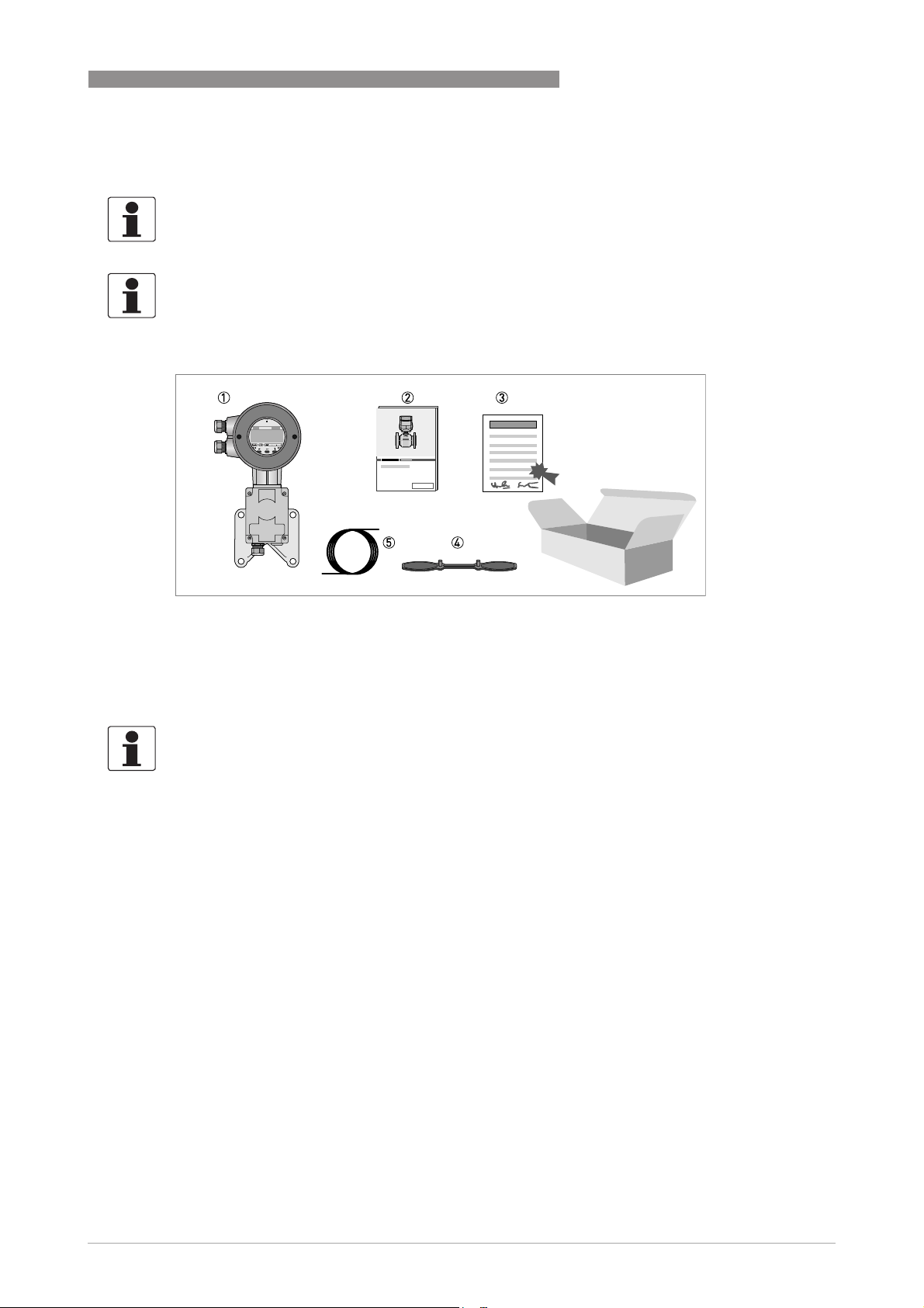
Figure 2-1: Standard scope of delivery, independent from the sensor version illustrated below
1 Signal converter UFC 030 in ordered version
2 Product documentation
3 Factory calibration report
4 Special wrench for opening the converter housing
5 Signal cable
INFORMATION!
Assembly materials and tools are not part of the delivery. Use the assembly materials and tools
in compliance with the applicable occupational health and safety directives.
www.krohne.com12/2013 - 4002393201- HB UFM 530 HT R02 en
9
Page 10
2 DEVICE DESCRIPTION
2.2 Device description
The UFM 530 HT is a bi-directional flowmeter (the arrow on the flowmeter indicates the positive
direction). It consists of a UFS 500 HT flow sensor and an UFC 030 signal converter.
The signal converter is installed separately from the high-temperature flow sensor.
The flow sensor is designed for process temperatures between -25...+500°C / -13...+932°F (Ex
hazardous areas are limited to -25...+440°C / -13...+824°F) and is manufactured from
316 stainless steel. Depending on the diameter it uses single beam or dual beam technology. All
coax cables are protected with metal tubes. On top of the flow sensor a connection box is
mounted.
INFORMATION!
Other diameters, pressure classes, materials or customized designs are available on request.
UFM 530 HT
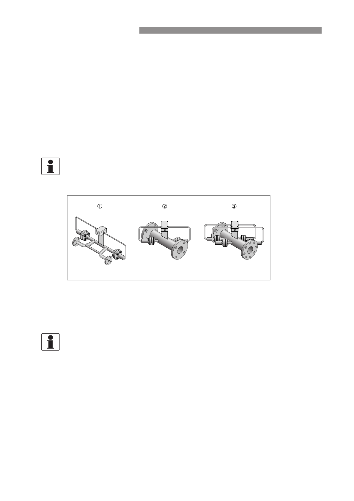
Figure 2-2: Available sensor versions
1 Building construction "single beam" (DN25...40)
2 Building construction "single beam" (DN50...80)
3 Building construction "dual beam" (≥DN100)
2.3 Nameplates
INFORMATION!
Look at the device nameplate to ensure that the device is delivered according to your order.
Check for the correct supply voltage printed on the nameplate.
10
www.krohne.com 12/2013 - 4002393201- HB UFM 530 HT R02 en
Page 11
UFM 530 HT
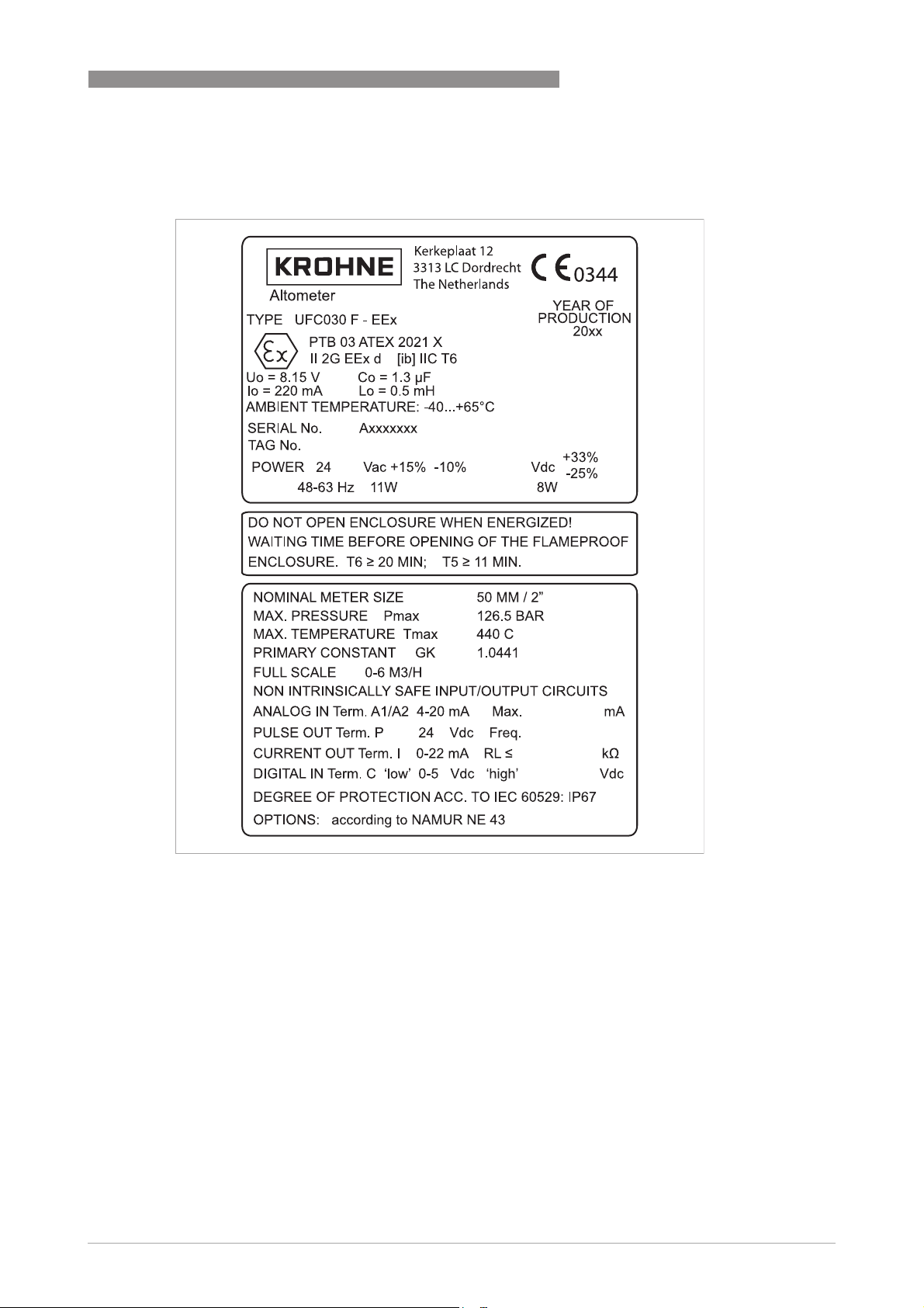
2.4 Example nameplate
DEVICE DESCRIPTION 2
Figure 2-3: Example of nameplate
www.krohne.com12/2013 - 4002393201- HB UFM 530 HT R02 en
11
Page 12
3 INSTALLATION
3.1 General notes on installation
INFORMATION!
Inspect the cartons carefully for damages or signs of rough handling. Report damage to the
carrier and to the local office of the manufacturer.
INFORMATION!
Do a check of the packing list to make sure that you have all the elements given in the order.
INFORMATION!
Look at the device nameplate to ensure that the device is delivered according to your order.
Check for the correct supply voltage printed on the nameplate.
3.2 Storage
• Store the device in a dry, dust-free location.
• Avoid continuous direct sunlight.
• Store the device in its original packaging.
• Storage temperature: -50...+70°C / -58...+158°F
UFM 530 HT
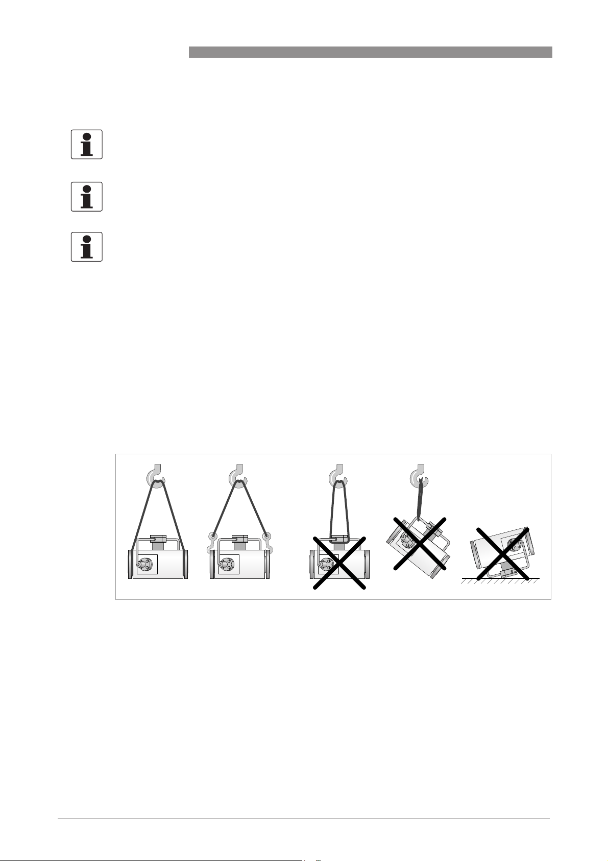
3.3 Transport
Figure 3-1: Correct lifting with the help of straps or crane hooks.
12
www.krohne.com 12/2013 - 4002393201- HB UFM 530 HT R02 en
Page 13
UFM 530 HT
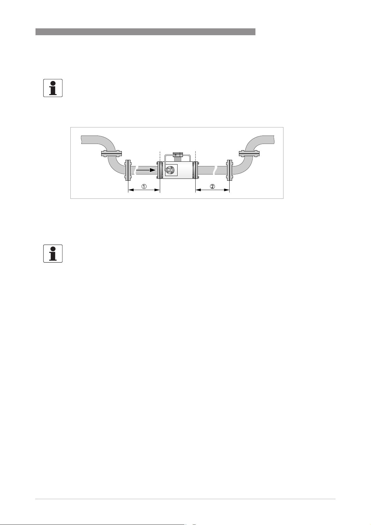
3.4 Inlet and outlet
INFORMATION!
To avoid measuring errors and to get proper measuring results an inlet section upstream and an
outlet section downstream is necessary. Regard the following illustration and table and regard
the information for different fluid products:
Figure 3-2: Recommended straight inlet and outlet
1 DN25...80: ≥ 50 DN
DN100...300: ≥ 15 DN
2 DN25...80: ≥ 10 DN
DN100...300: ≥ 5DN
INSTALLATION 3
INFORMATION!
Different fluid products
Different fluid products
Different fluid productsDifferent fluid products
To mix different fluid products, install the flow meter upstream of mixing point or at minimum
distance of 30 DN downstream of the mixing point.
www.krohne.com12/2013 - 4002393201- HB UFM 530 HT R02 en
13
Page 14
3 INSTALLATION
3.5 Mounting
3.5.1 Mounting position of the flow sensor
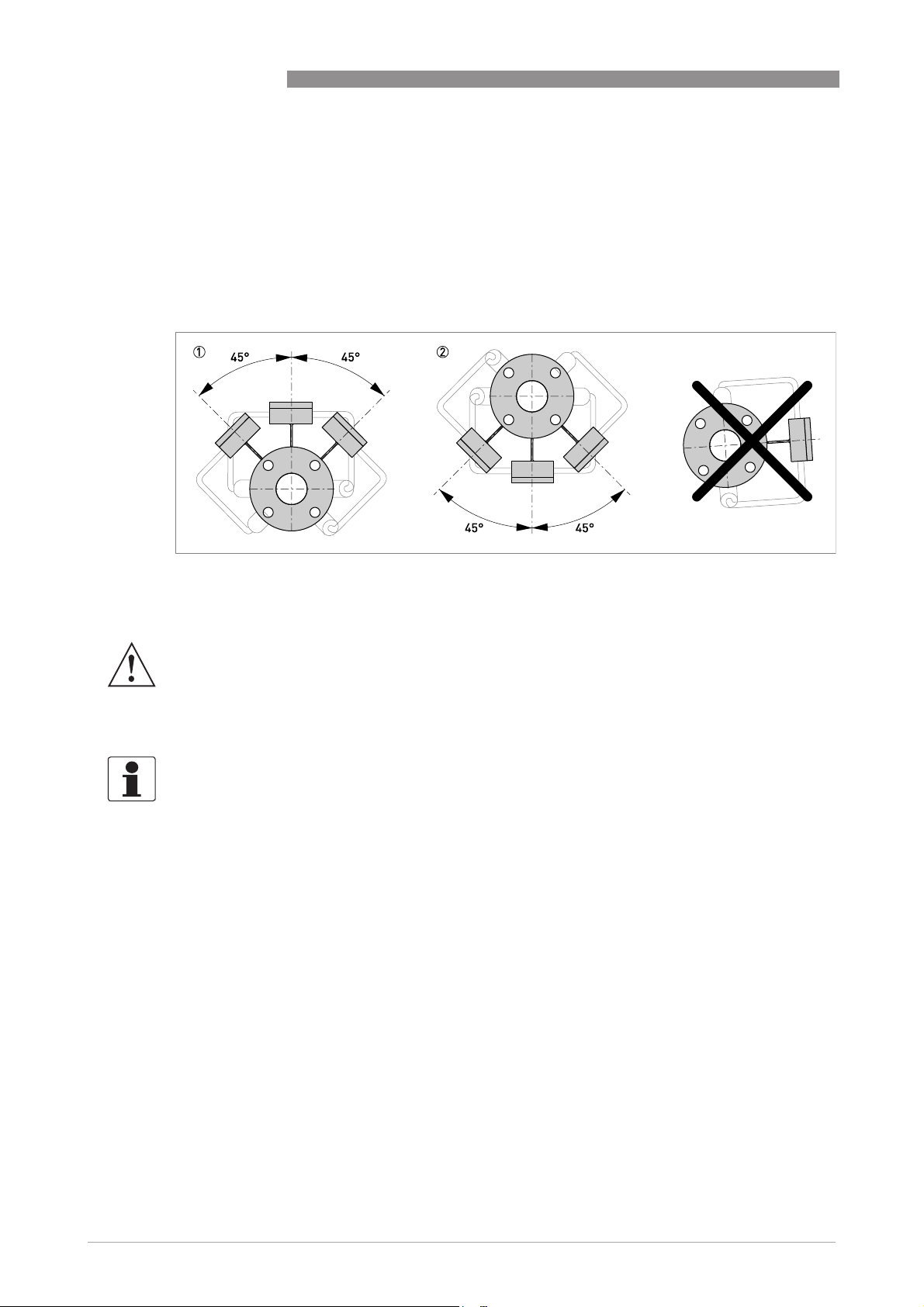
Installation of the flow sensor is allowed in horizontal, slightly ascending and vertical pipe
sections with up going flow direction (see next section). If installed in a horizontal or slightly
ascending pipeline, the connection box of the flow sensor has to be up or down.
UFM 530 HT
Figure 3-3: Allowed position of the flow sensor (up and down)
WARNING!
Do not unscrew the flanged transducer construction. This will cause direct contact with the high
temperature liquid running through the flow sensor.
3.5.2 Mounting location of the flow sensor
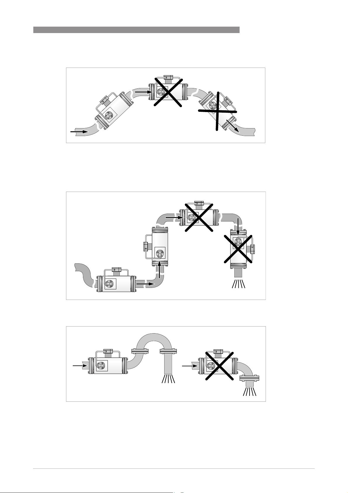
INFORMATION!
For proper flow measurement the measuring tube must be completely filled at all times. When
the sensors become non-wetted, a loss of signal message will be displayed. There is no damage
when this occurs.
Observe the following precautions to avoid measuring errors or malfunctioning of the flow meter
due to gas or air inclusions or an empty pipe.
Since gas will collect at the highest point of a pipe, installation of the flowmeter at that location
should always be avoided. In long horizontal pipes the flow meter has to be installed in a slightly
ascending pipe section. If not possible, ensure adequate velocity to prevent air, gas or vapour
from collecting in the upper part of the flow tube.
14
www.krohne.com 12/2013 - 4002393201- HB UFM 530 HT R02 en
Page 15
UFM 530 HT
INSTALLATION 3
Figure 3-4: Avoid locations where gas can be present.
Also installation in a down going pipe should be avoided since a completely filled pipe may not be
guaranteed due to cascading effects. Additionally flow profile distortion is possible.
Figure 3-5: Avoid locations where gas can be present
Figure 3-6: Ensure you have a completely filled pipe.
www.krohne.com12/2013 - 4002393201- HB UFM 530 HT R02 en
15
Page 16
3 INSTALLATION
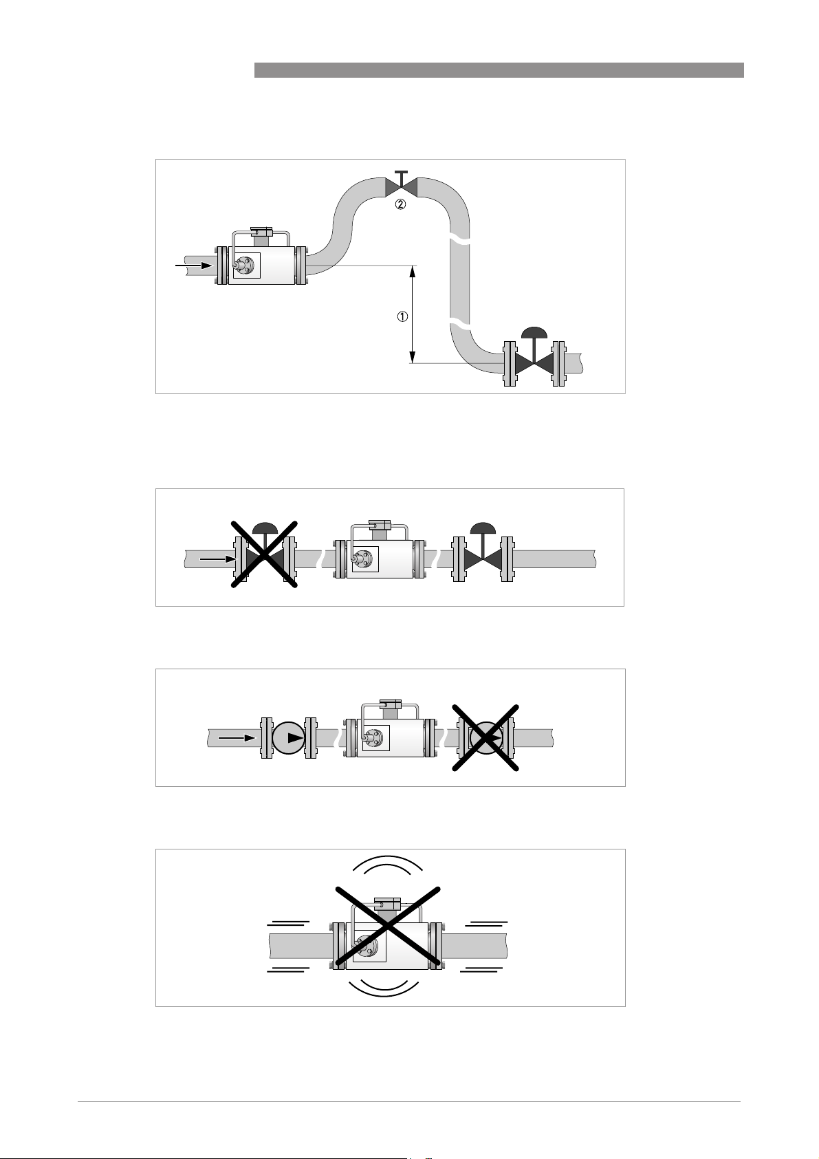
Figure 3-7: Air vent
1 Level difference > 5 m / 16 ft
2 Install an air vent.
UFM 530 HT
Figure 3-8: Install control valve downstream of the flow meter.
Figure 3-9: Install pump upstream of flowmeter.
16
Figure 3-10: Avoid installation in vibrating pipelines.
www.krohne.com 12/2013 - 4002393201- HB UFM 530 HT R02 en
Page 17
UFM 530 HT
3.5.3 Insulation
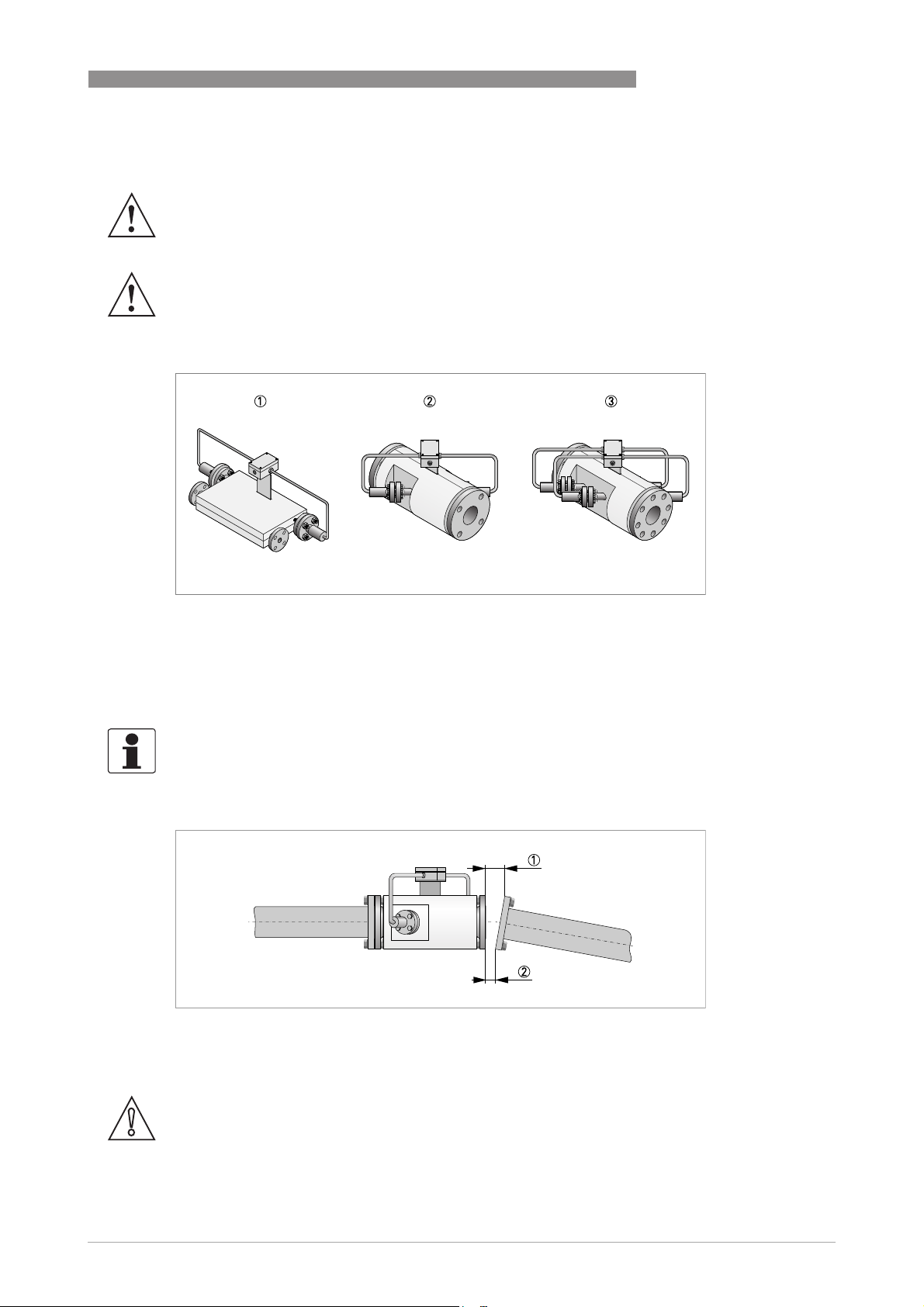
WARNING!
Complete insulation of the UFS 500 HT flow sensor is prohibited. Insulation is allowed up to the
first flange of each transducer.
WARNING!
The connection box and the flanged transducers require adequate cooling by ambient air and
must be protected against heat radiation by surrounding equipment.
INSTALLATION 3
Figure 3-11: Approved insulations.
1 Building construction "single beam" for DN25...40
2 Building construction "single beam" for DN50...80
3 Building construction "dual beam" for ≥ DN100
3.5.4 Pipe flanges
INFORMATION!
Refer to dimensional drawings for flange spacing and in addition allowance for thickness of
gaskets.
Figure 3-12: Maximum deviation between flanges
1 L
max
2 L
min
CAUTION!
Max. permissible deviation of pipe flange faces:
- L
L
max
≤ 0.5 mm / 0.02"
min
www.krohne.com12/2013 - 4002393201- HB UFM 530 HT R02 en
17
Page 18
3 INSTALLATION
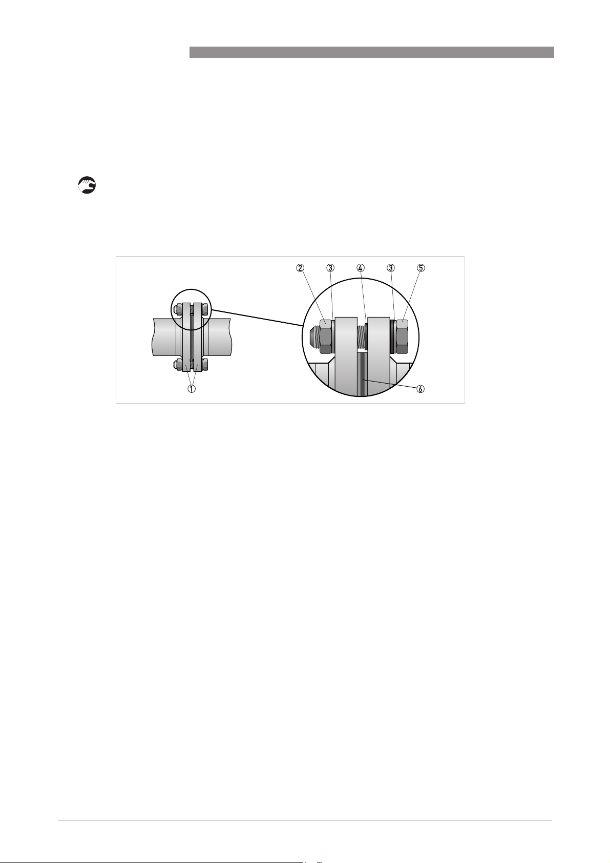
3.5.5 Pipes with cathodic protection
Pipes with electric corrosion protection are generally insulated inside and outside so that the
fluid has no conductive connection to the ground. The flow meter must be insulated from the
pipe. Observe the following instructions when installing the flow meter:
• The pipe flanges must be connected to each other using a copper cable (L), but must not be
connected to the flowmeter.
• The bolts for the flange connections and the gaskets must be insulated. Use sleeves and
washers that are made of insulating material (these must be provided by customer).
UFM 530 HT
Figure 3-13: Cathodic protection
1 Flanges (left one: of flow sensor, right one: of pipe)
2 Nut
3 Washer
4 Insulating sleeve
5 Bolt
6 Gasket
18
www.krohne.com 12/2013 - 4002393201- HB UFM 530 HT R02 en
Page 19

UFM 530 HT
4.1 Safety instructions
DANGER!
All work on the electrical connections may only be carried out with the power disconnected. Take
note of the voltage data on the nameplate!
DANGER!
Observe the national regulations for electrical installations!
DANGER!
For devices used in hazardous areas, additional safety notes apply; please refer to the Ex
documentation.
WARNING!
Observe without fail the local occupational health and safety regulations. Any work done on the
electrical components of the measuring device may only be carried out by properly trained
specialists.
ELECTRICAL CONNECTIONS 4
INFORMATION!
Look at the device nameplate to ensure that the device is delivered according to your order.
Check for the correct supply voltage printed on the nameplate.
4.2 Power supply of the converter
Environmental conditions
The flowmeter is designed to operate safe under the following conditions. Observe them before
the connection to the mains supply voltage is established:
• Indoor and outdoor use, usable up to protection category IP67 according to IEC 60529
(Note: IP67 is only warranted when using suitable cabling with the cable glands and covers
mounted as specified).
• Maximum altitude: up to 2000 m above see level.
• Maximum relative humidity: up to 80%.
• Operation ambient temperature range: -40...+65°C.
• Storage temperature range: -40...+70°C.
CAUTION!
Never allow dirt to accumulate on the gasket of the rear (blind) cover. A dirty gasket has to be
cleaned, a damaged gasket must be replaced immediately.
www.krohne.com12/2013 - 4002393201- HB UFM 530 HT R02 en
19
Page 20
4 ELECTRICAL CONNECTIONS
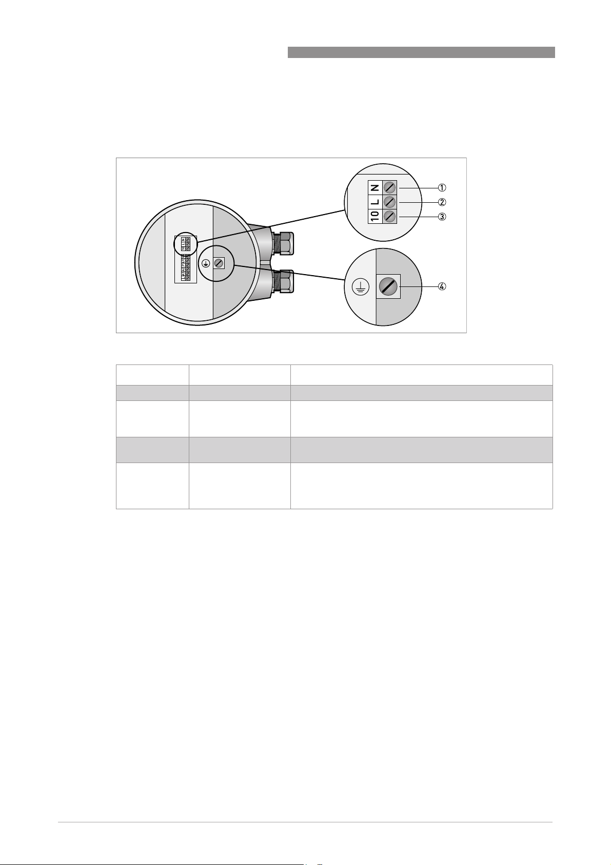
Before the cables can be fastened to the power supply terminal, the rear (blind) cover has to be
removed.
Figure 4-1: Terminals for power supply
UFM 530 HT
Item number Function Specification
1 Neutral power supply.
2 Life power supply. Mains voltage AC supply: 100 VAC < U < 240 VAC (-15%, +10%),
SELV AC/DC supply: 24 VDC (-25%, +33%), 24 VAC (-10%,
+15%).
3 Reserved ground
connection.
4 Protective ground
connection (PE),
Functional ground
connection (FE).
Not for protective earthing.
Protective conductor clamp terminal. Conductors up to
4mm2(11 AWG) need to be connected to this terminal.
20
www.krohne.com 12/2013 - 4002393201- HB UFM 530 HT R02 en
Page 21
UFM 530 HT
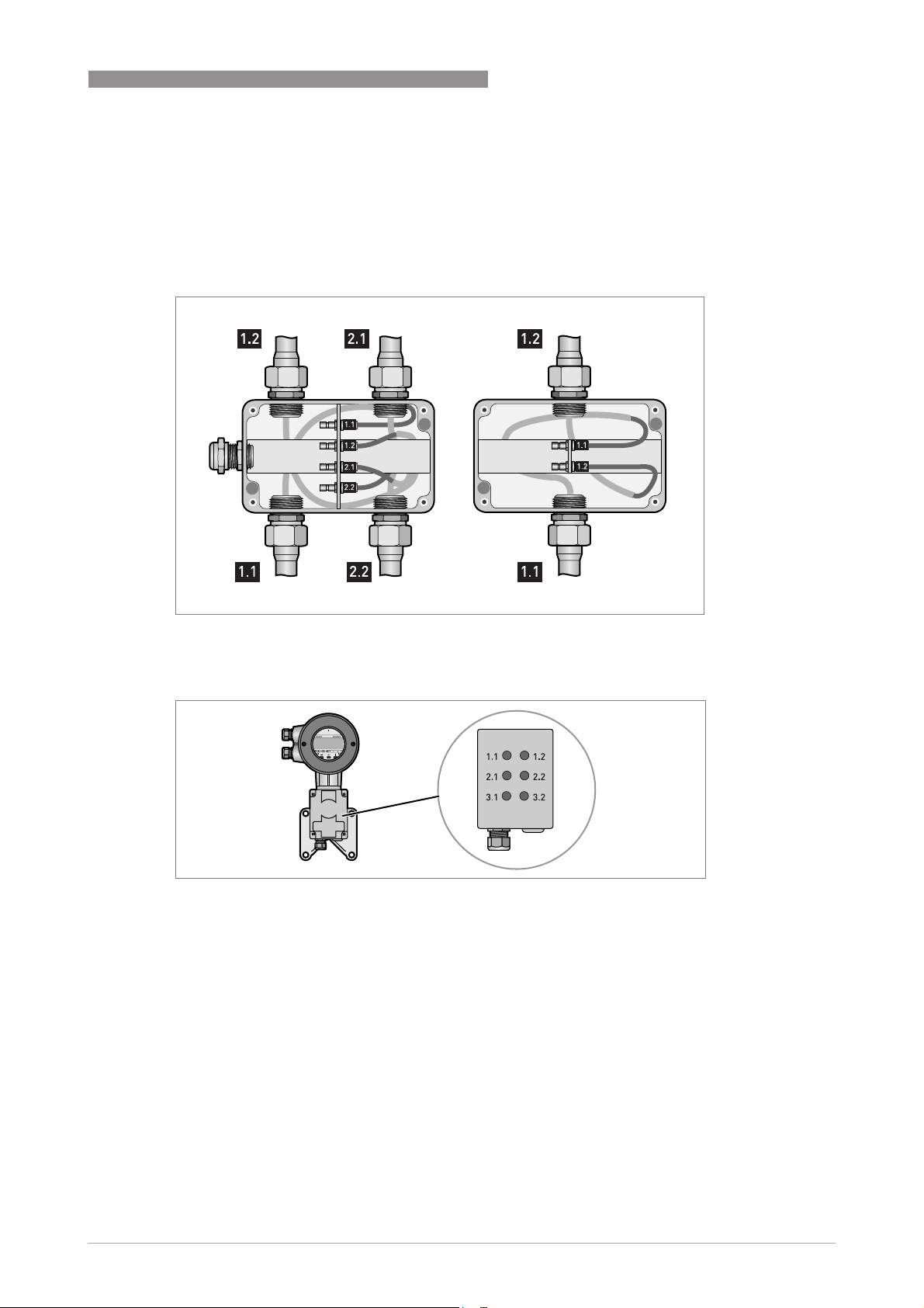
4.3 Connection of signal cables
Connect the signal cable from the connection box of the UFS 500 HT sensor to the UFC 030
signal converter according to underneath drawings for the single beam and dual beam
construction.
ELECTRICAL CONNECTIONS 4
Figure 4-2: Connection of the sensor cables for dual beam (left) and
single beam (right) building construction (sensor side)
Figure 4-3: Connection of the sensor cables, converter side
www.krohne.com12/2013 - 4002393201- HB UFM 530 HT R02 en
21
Page 22

4 ELECTRICAL CONNECTIONS
4.4 Electrical connections of the signal inputs and outputs
CAUTION!
For wiring of the signal inputs and outputs it is advised to use unshielded twisted pairs.
CAUTION!
Please observe instrument polarity: current (I) is always flowing towards I, C, P, A1, A2 terminals
(current sink).
The signal inputs and outputs terminals are located in the converter terminal box. It is
accessible after removing the rear (blind) cover of the converter. There are versions for non Ex
and for Ex applications.
4.4.1 Non Ex versions
Non Ex standard version
UFM 530 HT
Figure 4-4: Terminals for standard instrument.
Terminal Function Specification
1 DC power supply from converter for active
2 Combined current output (I) and digital
3 Pulse / frequency output. I
4 Analog input 2, for temperature or
5 Analog input 1, for temperature
6 Common ground -
wiring of inputs and outputs.
input (C). Current output (I) includes
®
-Communication.
HART
pressure measurement.
measurement.
22 VDC at full load, 24 VDC maximum,
I ≤ 100 mA.
Current output (I): I ≤ 22 mA,
≤ 680 Ω, U
R
load
Digital input (C): low = 0...5 VDC,
high = 15...32 VDC (will be switched off
when current output activated).
= 150 mA, U
max
maximal frequency = 2 kHz.
0(4)...20 mA, Ri= 58,2 Ω, fuse = 50 mA.
0(4)...20 mA, Ri= 58,2 Ω, fuse = 50 mA.
max
max
= 15 VDC.
CAUTION!
Never use the active and passive mode at the same terminal simultaneously.
®
If HART
-Communication is used, do not connect the pulse/frequency output P in active mode.
=32VDC/ 24VAC,
22
www.krohne.com 12/2013 - 4002393201- HB UFM 530 HT R02 en
Page 23

UFM 530 HT
ELECTRICAL CONNECTIONS 4
INFORMATION!
The electrical input and output signals can be connected either in active or in passive mode. In
active mode DC supply voltage is provided from the terminal V+. In passive mode supply voltage
is provided from an external source.
Non Ex version with Profibus PA
Figure 4-5: Terminals for instrument with Profibus PA (non Ex).
Terminal Function Specification
1 Communication connection - For Fieldbus communication
2 Communication connection + For Fieldbus communication
3 Combined current output (I), digital
input (C) and Pulse / frequency output.
Current output (I) includes HART
Communication.
4 Analog input 2, for temperature or
pressure measurement.
5 Analog input 1, for temperature
measurement.
6 Common ground
®
-
Current output (I): I ≤ 22 mA,
R
≤ 680 Ω, U
load
Digital input (C): low = 0...5 VDC,
high = 15...32 VDC (will be switched off
when current output activated).
Pulse output: I
U
= 32 VDC / 24 VAC, maximal
max
frequency = 2 kHz.
0(4)...20 mA, Ri= 58,2 Ω, fuse = 50 mA.
0(4)...20 mA, Ri= 58,2 Ω, fuse = 50 mA.
max
= 150 mA,
max
= 15 VDC.
www.krohne.com12/2013 - 4002393201- HB UFM 530 HT R02 en
23
Page 24

4 ELECTRICAL CONNECTIONS
Non Ex HiPower version
Figure 4-6: Terminals for non Ex HiPower instrument.
Terminal Function Specification
UFM 530 HT
1 DC power supply from converter for active
wiring of inputs and outputs.
2 Combined current output (I) and digital
input (C). Current output (I) includes
®
HART
-Communication.
22 VDC at full load, 24 VDC maximum,
I ≤ 100 mA.
Current output (I): I ≤ 22 mA,
R
≤ 680 Ω, U
load
max
= 15 VDC.
Digital input (C): low = 0...5 VDC,
high = 15...32 VDC (will be switched off
when current output activated).
3 Pulse / frequency output. I
= 150 mA, U
max
=32VDC/ 24VAC,
max
maximal frequency = 2 kHz.
4 Analog input 2, for temperature or
0(4)...20 mA, Ri= 58,2 Ω, fuse = 50 mA.
pressure measurement.
5 Analog input 1, for temperature
0(4)...20 mA, Ri= 58,2 Ω, fuse = 50 mA.
measurement.
6 Common ground -
24
www.krohne.com 12/2013 - 4002393201- HB UFM 530 HT R02 en
Page 25

UFM 530 HT
4.4.2 Ex versions
WARNING!
The electrical input and output signals must be connected in passive mode. The supply voltage
must be provided from an external source.
Ex standard version
Figure 4-7: Terminals for Ex standard instrument
ELECTRICAL CONNECTIONS 4
Terminal Function Specification
1 Neutral mains power supply 100...240 VAC, 24 VAC or 24 VDC
2 Live mains power supply 100...240 VAC, 24 VAC or 24 VDC
3 Combined current output (I) and digital
4 Pulse / frequency output I
5 Analog input 2, for temperature or
6 Analog input 1, for temperature
7 Common ground
input (C). Current output (I) includes
®
-Communication.
HART
pressure measurement.
measurement.
Current output (I): I ≤ 22 mA,
≤ 680 Ω, U
R
load
Digital input (C): low = 0...5 VDC,
high = 15...32 VDC (will be switched off
when current output activated).
= 150 mA, U
max
maximal frequency = 2 kHz.
0(4)...20 mA, Ri= 58,2 Ω, fuse = 50 mA.
0(4)...20 mA, Ri= 58,2 Ω, fuse = 50 mA.
= 15 VDC.
max
=32VDC/ 24VAC,
max
www.krohne.com12/2013 - 4002393201- HB UFM 530 HT R02 en
25
Page 26

4 ELECTRICAL CONNECTIONS
Ex NAMUR version
Figure 4-8: Terminals for Ex instrument with NAMUR
Terminal Function Specification
1 Neutral mains power supply 100...240 VAC, 24 VAC or 24 VDC
2 Live mains power supply 100...240 VAC, 24 VAC or 24 VDC
3 Combined current output (I) and digital
input (C). Current output (I) includes
®
HART
-Communication.
4 Pulse / frequency output I
5 Ground for pulse output
6 Analog input 1, for temperature
7 Common ground
measurement.
UFM 530 HT
Current output (I): I ≤ 22 mA,
R
≤ 680 Ω, U
load
Digital input (C): low = 0...5 VDC,
high = 15...32 VDC (will be switched off
when current output activated).
= 150 mA, U
max
maximal frequency = 2 kHz.
0(4)...20 mA, Ri= 58,2 Ω, fuse = 50 mA.
= 15 VDC.
max
=32VDC/ 24VAC,
max
INFORMATION!
The current output of the UFC 030 F-EEx can be set according to NAMUR NE43. The current
output will go either to 3.6 or 21.5 mA in case of failure indication.
26
www.krohne.com 12/2013 - 4002393201- HB UFM 530 HT R02 en
Page 27

UFM 530 HT
ELECTRICAL CONNECTIONS 4
The following Ex-i Modis versions have two Modis modules, providing intrinsically safe input /
output circuits. Modis versions don't have analogue inputs A1 / A2.
Ex-i (Modis) version
Figure 4-9: Terminals for instrument with Ex-i (Modis)
Terminal Function Specification
1 Neutral mains power supply 100...240 VAC, 24 VAC or 24 VDC
2 Live mains power supply 100...240 VAC, 24 VAC or 24 VDC
3 Ground for pulse, frequency or status
output
4 Pulse, frequency or status output I
5 Current output Current output (I): I ≤ 22 mA,
6 Ground for current output
= 150 mA, U
max
maximal frequency = 2 kHz.
R
≤ 680 Ω, U
load
=32VDC/ 24VAC,
max
= 15 VDC.
max
www.krohne.com12/2013 - 4002393201- HB UFM 530 HT R02 en
27
Page 28

4 ELECTRICAL CONNECTIONS
Ex-i (Modis) version with Profibus PA
Figure 4-10: Terminals for Ex-i (Modis) version with Profibus PA
Terminal Function Specification
1 Neutral mains power supply 100...240 VAC, 24 VAC or 24 VDC
2 Live mains power supply 100...240 VAC, 24 VAC or 24 VDC
3 Profibus communication -
4 Profibus communication +
5 Current output Current output (I): I ≤ 22 mA,
6 Ground for current output
R
load
≤ 680 Ω, U
max
UFM 530 HT
= 15 VDC.
28
www.krohne.com 12/2013 - 4002393201- HB UFM 530 HT R02 en
Page 29

UFM 530 HT
4.5 Connection diagram examples
INFORMATION!
The connection diagrams on the next pages are valid for most versions. However, not all
versions have the same connection possibilities. Versions that don't have the V+ terminal (for
instance Ex versions) can only be connected in a passive way, e.g. by using an external power
supply.
4.5.1 Current output
Current output active
• V+: 22 VDC at full load, 24 VDC maximum, I ≤ 100 mA
≤ 680 Ω
• R
L
• I < 22 mA
• U
= 15 VDC
max
ELECTRICAL CONNECTIONS 4
Figure 4-11: Current output (active)
Current output passive
• U
• I ≥ 22 mA (for supply)
• For Ex-i modis versions: I = 4..20 mA
• For Ex-i modis versions: R
Figure 4-12: Current output (passive)
= 15...24 VDC
ext
(For Ex-i modis versions: U
= 8,1...30 VDC)
ext
≤ (U
L
- 8) / 0,022
ext
INFORMATION!
Ex-i modis versions do not have an "I/C" terminal. Use the "I" terminal instead.
www.krohne.com12/2013 - 4002393201- HB UFM 530 HT R02 en
29
Page 30

4 ELECTRICAL CONNECTIONS
4.5.2 Pulse output
Pulse output active
• V+: 22 VDC at full load, 24 VDC maximum, I ≤ 100 mA
• Ri ≥ 470 Ω
• frequency ≤ 2 kHz
Figure 4-13: Pulse output (active)
UFM 530 HT
Pulse output passive
• U
• I ≤ 150 mA
• Ri ≥ 470 Ω
• frequency ≤ 2 kHz
Figure 4-14: Pulse output (passive)
≤ 32 VDC or U ≤ 24 VAC
ext
(For Ex-i modis versions: U
= 6...30 VDC)
ext
(For Ex-i modis versions: I ≤ 110 mA)
INFORMATION!
Ex-i modis versions have different terminal codings.
30
www.krohne.com 12/2013 - 4002393201- HB UFM 530 HT R02 en
Page 31

UFM 530 HT
Figure 4-15: Pulse output (passive) for Ex-i Modis
4.5.3 Digital input
INFORMATION!
The digital input will be switched off when the current output is activated.
Digital input active
• V+: 22 VDC at full load; 24 VDC maximum, I ≤ 100 mA
• Low = 0...5 VDC
• High = 15...32 VDC
ELECTRICAL CONNECTIONS 4
Figure 4-16: Digital input (active)
Digital input passive
• U
• I ≥ 1.5 mA
• Low = 0...5 VDC
• High = 15...32 VDC
= 15...30 VDC
ext
www.krohne.com12/2013 - 4002393201- HB UFM 530 HT R02 en
31
Page 32

4 ELECTRICAL CONNECTIONS
Figure 4-17: Digital input (passive)
4.5.4 Analog input
Analog input
• 0 (4)...20 mA
• Ri = 58.2 Ω
• Fuse 50 mA
UFM 530 HT
Figure 4-18: Analog input
32
www.krohne.com 12/2013 - 4002393201- HB UFM 530 HT R02 en
Page 33

UFM 530 HT
5.1 Start-up procedure
DANGER!
Hazardous voltages are present within this product during normal operation. Do not operate it
with the covers removed!
When powered, "start-up" is shown at the display for a short time. After that the normal
measuring mode starts.
INFORMATION!
The flowmeter is programmed at the factory according to your order. No changes are necessary.
START-UP 5
www.krohne.com12/2013 - 4002393201- HB UFM 530 HT R02 en
33
Page 34

6 OPERATION
6.1 Signal converter: front panel and operating keys
The front panel and its operating keys are accessible after removing the front cover of the
electronics section (use the special wrench for it). If it is not allowed to open the housing, for
instance in hazardous areas, you can program the converter with the magnetic pin.
CAUTION!
When removing the cover, do not damage the screw thread and the gasket, never allow dirt to
accumulate and make sure that they are well greased using Teflon. A damaged gasket must be
replaced immediately!
UFM 530 HT
1 Magnetic sensors to program the signal converter by means of a hand-held bar magnet (optional) without having to
remove the front cover (left sensor is equivalent to the "→" ke y, r igh t se nso r to "↑" key and sensor at the top to "^" key.
2 Compass needles.
3 Measured value ("E" stands for "Exponent").
4 Unit of measured value.
5 Indication of actual displayed value.
6 Operating keys (→, ^, ↑) for programming the signal converter.
Function of operating keys depending on selected mode
Key / symbol Measuring mode Menu mode Data level
→ Go to the parameter setting
mode. If access CODE 1 is
activated, CODE 1 must be
entered first.
^ Go to the error/totalizer
reset mode (via CODE 2).
↑ Cycle through measured
values.
Go to the next, lower menu
level.
Return to the previous
(higher) menu level or
leave the menu mode.
Cycle through menu
options within actual menu
level.
Go to the next character or
change line (only when two
lines are displayed).
Accept entered value.
Raise active digit.
34
www.krohne.com 12/2013 - 4002393201- HB UFM 530 HT R02 en
Page 35

UFM 530 HT
6.2 Available versions
INFORMATION!
The flowmeter is programmed at the factory according to your order. No changes are necessary.
All standard UFC 030 signal converters can be programmed in menu 3.02.01.
1. Standard version
1. Standard version
1. Standard version1. Standard version
2. CORR T: on-site interchangeable to "standard".
2. CORR T: on-site interchangeable to "standard".
2. CORR T: on-site interchangeable to "standard".2. CORR T: on-site interchangeable to "standard".
Temperature correction via analogue input 1 (temp range -50... +150°C) ; with this version the
outputs are non-Ex-I.
3. CORR T+P: on-site interchangeable to "standard".
3. CORR T+P: on-site interchangeable to "standard".
3. CORR T+P: on-site interchangeable to "standard".3. CORR T+P: on-site interchangeable to "standard".
Temperature correction via analogue input 1, pressure correction via analogue input 2 (press
range 0...100 bar) ; with this version the outputs are Ex-I.
Corrected volume calculation can be done based on temperature correction or temperature and pressure correction.
The volume correction factor is based on API 2540; chapter 11.1 for the temperature correction
and chapter 11.2 for the pressure correction.
For liquid oil products the volume correction factors can be estimated as 0.1% per degree
Celsius and 0.01% per bar as a rule of thumb. Therefore for normal industrial processes these
corrections are hardly ever applied.
OPERATION 6
4. HEAT: on-site interchangeable to "standard".
4. HEAT: on-site interchangeable to "standard".
4. HEAT: on-site interchangeable to "standard".4. HEAT: on-site interchangeable to "standard".
The UFC 030 signal converter is programmed for energy measurement, based on temperature
measurements connected via analogue inputs A1 and A2 (temperature range: -50...+150°C);
with this version the outputs are non-Ex-I. The following settings are needed:
No. of menu Display text Setting/description and functions
3.02.02 INP1 4mA minimum value of temperature sensor 1 on inlet
3.02.03 INP1 20mA maximum value of temperature sensor 1 on inlet
3.02.04 INP1 4mA minimum value of temperature sensor 2 on outlet
3.02.05 INP1 20mA maximum value of temperature sensor 2 on outlet
3.02.12 full scale xxx (unit yyy)
3.03.02 function
totalizer
3.03.05 unit for total
energy
3.05.01 function pulse
output
3.05.10 pulse/unit select unit
select direction
select unit
CORR FLOW
www.krohne.com12/2013 - 4002393201- HB UFM 530 HT R02 en
35
Page 36

6 OPERATION
5. BATCH: on-site interchangeable to "standard".
5. BATCH: on-site interchangeable to "standard".
5. BATCH: on-site interchangeable to "standard".5. BATCH: on-site interchangeable to "standard".
The following settings are needed:
No. of menu Display text Setting/description and functions
UFM 530 HT
3.04.01 FUNCTION
3.05.01 FUNCTION
3.06.01 FUNCTION
3.02.13 BATCH VOL xxx(unit yyy)
6. MODIS: setting can not be changed.
6. MODIS: setting can not be changed.
6. MODIS: setting can not be changed.6. MODIS: setting can not be changed.
(current
output)
(pulse output)
(digital output)
OFF
BATCH
BATCH
The analogue inputs 1 and 2 are not available in this version.
The Ex-I 1 version has a current output (incl. HART
The Ex-I 2 version has a current output (incl. HART
INFORMATION!
Depending on the programming of function 3.03.07 the additional or selectable indications can
be manually selected by pressing ↑ key, or they are alternating with the display of the measured
value(s). The corrected volume flow indication or volume flow totalizer indication is marked with
the letter "C" at the left of the display's second (middle) line. The batch totalizer indication is
marked with the letter "B".
6.3 Signal converter: menu structure
INFORMATION!
Since the UFC 030 converter can be equipped with different options, the availability of certain
options depends on the function of the converter.
®
) and a pulse output.
®
) and a Profibus PA output.
The menu structure consists of five user accessible parts. They are described on the following
pages.
Error / totalizer menu
No. of menu Display text Setting/description and functions
0.00.01 VIEW ERR View error messages list.
0.00.02 RST ERR Reset error messages:
1) NO RESET: keep error messages list.
2) RESET: reset error messages list.
0.00.03 RST TOTAL Reset display totalizer(s). Note: all totalizer values are reset!
Only availabe when function 3.07.08 is set to YES. Available options:
1) RESET ALL: reset all totalizer values.
2) NO RESET: keep totalizer values.
36
www.krohne.com 12/2013 - 4002393201- HB UFM 530 HT R02 en
Page 37

UFM 530 HT
OPERATION 6
INFORMATION!
The functions in this menu are a subset of menu 3.00.00. They are selected in this menu as most
commonly used functions for a quick installation. Note: parameters set in these functions are
automatically set in both menus!
Operation menu
No. of menu Display text Setting/description and functions
1.01.00, FLOW
1.01.01 FULL SCALE Full-scale value for 100% volume flow rate.
1.01.02 ZERO VALUE Zero value.
1.01.03 ZERO CAL Zero calibration.
1.01.04 MASTER TC Master time constant.
1.01.05 LF CUTOFF Low-flow cut-off.
1.01.06 CUTOFF ON Cut-off active.
1.01.07 CUTOFF OFF Cut-off de-active.
1.02.00, DISPLAY
1.02.01 DISP FLOW Display of flow.
1.02.02 FUNCT TOT Function of totalizer.
1.02.03 TOTAL VOL Display of totalizer.
1.03.00, PULSE OUTP (Pulse output)
1.03.01 PULSE RATE Pulse frequency value for 100% scale.
1.03.02 PULSE/UNIT Pulse value per volume flow unit.
1.03.03 PULSE/UNIT Pulse value per energy unit.
www.krohne.com12/2013 - 4002393201- HB UFM 530 HT R02 en
37
Page 38

6 OPERATION
Test functions menu
No. of menu Display text Setting/description and functions
This menu is for testing the display, the in- and outputs and for information on hard- and software
numbers.
2.01.00, DISPLAY
2.01.01 DISPLAY Test display, lights all pixels (end with ^ key).
2.02.00, OUTPUTS
2.02.01 CURRENT Test current output (0, 4, 12, 20 and 22 mA).
2.02.02 PULSE Test pulse/frequency output (1, 10, 100, 1000 and 2000 Hz).
2.03.00, INPUTS
2.03.01 AN INP 1 Test analog input 1.
2.03.02 AN INP 2 Test analog input 2.
2.03.03 DIG INPUT Test digital input. Measure level at digital input.
2.03.04 SENSOR Sensor status: good, open, short
UFM 530 HT
Use ↑ key to go to next value. Displayed value directly present at
current output. End with ^ key.
Use ↑ key to advance. Displayed value directly present at pulse
output. End with ^ key.
Measure current at analog input 1.
End with ^ key.
Measure current at analog input 2.
End with ^ key.
End with ^ key.
2.04.00, DEV INFO (Device information)
2.04.01 MANUFACT Display manufacturer.
2.04.02 MODEL NO Display model number.
2.04.03 SERIAL NO Display serial number.
2.04.04 UP2 HW NO Display μP2 hardware number.
2.04.05 UP2 SW NO Display μP2 software number.
2.04.06 FRNT HW NO Display front end hardware number.
2.04.07 DSP HW NO Display D.S.P. hardware number.
2.04.08 DSP SW NO Display D.S.P. software number.
2.04.09 TIME COUNT Display time counter.
38
www.krohne.com 12/2013 - 4002393201- HB UFM 530 HT R02 en
Page 39

UFM 530 HT
OPERATION 6
Installation menu
No. of menu Display text Setting/description and functions
3.01.00, FLOW (Volume flow parameters)
3.01.01 FULL SCALE Full-scale value for 100% volume and flow rate units (see
3.01.02 ZERO VALUE Although zero calibrated at the factory the flow sensor might still give
3.01.03 ZERO CAL Zero calibration (see function 1.01.03). Note: Carry out only at "zero"
3.01.04 MASTER TC The master time constant apply for the display and the current and
3.01.05 LF CUTOFF Low-flow cut-off for display and outputs.
3.01.06 CUTOFF ON Cut off "active" value.
3.01.07 CUTOFF OFF Cut off "de-active" value. Note: value "off" must be greater than value
3.01.08 METER SIZE The nominal diameter of the measuring tube. See the flow sensor
3.01.09 GK VALUE At the factory, each flow sensor is calibrated and supplied with a
3.01.10 FLOW DIR The forward flow direction is indicated with an arrow on the flow
function 1.01.01). The selection of units may be limited to SI units
only.
Available units: m3/s, m3/min, m3/hr, L/s, L/min, L/hr,
US.Gal/s, US.Gal/min, US.Gal/hr, bbls/hr, bbls/day or free user
configurable unit, set by using function 3.07.05...3.07.07).
an offset flow reading, at "zero" flow in the pipeline. Available
settings:
1) FIXED: factory zero setting.
2) MEASURED: value measured with function 3.01.03 (ZERO CAL).
flow and with completely filled measuring tube!
Duration approximately 15s with display
indicating "BUSY":
1) STORE NO: preserve old zero value.
2) STORE YES: store new zero value.
pulse outputs. It does not apply for totalisation and for the current
output in F/R setting. If required, a different time constant value can
be set for the pulse/frequency output under Function 3.05.06.
Range: 0.02...99.99 s.
1) NO: fixed tripping points (ON = 0.1%, OFF = 0.2%).
2) YES: see function 3.01.06 and 3.01.07.
Range: 1 through 19% of Q
"on"!
Range: 2 through 20% of Q
nameplate. Selection of size from meter size table:
25...3000 mm / 1...120".
calibration constant (GK). This constant can be found on the flow
sensor nameplate and must equal the value on the flow sensor
nameplate.
Range: 0.02...20.
sensor. Available settings:
1) POSITIVE: If the actual flow is in the direction of the arrow then the
flow is in the positive direction and the converter will have a positive
flow reading.
2) NEGATIVE: reversed reading of the converter, useful when the
process flow direction is changed so the flow sensor will not need to
be reversed.
100%
100%
.
.
www.krohne.com12/2013 - 4002393201- HB UFM 530 HT R02 en
39
Page 40

6 OPERATION
No. of menu Display text Setting/description and functions
3.01.11 MIN VOS Minimum velocity of sound (VOS). Value used for I0% or P0% when
3.01.12 MAX VOS Maximum velocity of sound.Value used for I
3.02.00, VERSION
3.02.01 FUNCTION Function of converter. This is factory pre-set and can only be changed
3.02.02 INP1 4 mA 4 mA reference for analog input 1, 4 mA temperature reference.
3.02.03 INP1 20 mA 20 mA reference for analog input 1, 20 mA temperature reference.
3.02.04 INP2 4 mA 4 mA reference for analog input 2, 4 mA temperature reference.
3.02.05 INP2 20 mA 20 mA reference for analog input 2, 20 mA temperature reference.
3.02.06 INP2 4 mA 4 mA reference for analog input 2, 4 mA pressure reference.
3.02.07 INP2 20 mA 20 mA reference for analog input 2, 20 mA pressure reference.
3.02.08 K0 Product constant K0.
UFM 530 HT
function "VOS" selected in function 3.04.01 or 3.05.01.
Units: m/s or feet/s,
range: 0...4999 m/s (0...16.400 feet/s).
or P
function "VOS" selected in function 3.04.01 or 3.05.01. Note:
maximum value must be greater than minimum value!
Units: m/s or feet/s,
range: 1...4999 m/s (0...16.400 feet/s).
to standard from any setting:
1) STANDARD.
2) CORR T: temperature correction of the measured flow via analog
input 1.
3) CORR T + P: temperature and pressure correction of the measured
flow via analog input 1 (pressure) and analog input 2 (temperature).
4) HEAT: reserved for measurement of heat power and heat energy
totalisation.
5) BATCH: batch volume.
6) MODIS: Cannot be altered.
Unit: °Cor°F, range: -50...+150°C / -58...302°F.
Unit: °Cor°F, range: -50...+150°C / -58...302°F.
Unit: °Cor°F, range: -50...+150°C / -58...302°F.
Unit: °Cor°F, range: -50...+150°C / -58...302°F.
Unit: bar(a) or psi(a), range: 0...100 bar(a).
Unit: bar(a) or psi(a), range: 0...100 bar(a).
100%
100%
when
40
Range: 10-9...109.
3.02.09 K1 Product constant K1.
Range: 10-9...109.
3.02.10 K2 Product constant K2.
Range: 10-9...109.
3.02.11 DENSITY 15 Product density at T = 15°C/ 59°F.
Range: 500...2000 kg/m3.
3.02.12 FULL SCALE Heat measurement. Full scale setting and unit for heat power.
Available units: GJ/s, GJ/hr, MJ/s, MJ/hr, GCal/s, GCal/hr, MCal/s,
MCal/hr.
www.krohne.com 12/2013 - 4002393201- HB UFM 530 HT R02 en
Page 41

UFM 530 HT
OPERATION 6
No. of menu Display text Setting/description and functions
3.02.13 BATCH VOL Batch volume total size and units.
Availabe units: m3, Liter, US-Gallon, Barrel or user definable unit.
Range: 0.025...100000 m3.
3.03.00, DISPLAY.
3.03.01 DISP FLOW Display of flow. Available options:
1) RATE: full-scale units (flow is shown with the unit as set in function
3.01.01).
2) PERCENT: flow is shown as a percentage (0...100%) of the full
scale value.
3) NO DISPLAY: no flow is shown.
3.03.02 FUNCT TOT Function of totalizer. Two totalizers (counters) are available. The
3.03.03 DISP TOTAL Display of totalizer. A totalizer can be selected here for displaying:
3.03.04 TOTAL VOL Unit for volume totalizer. Note: the maximal value of the totalizer is
totalizer values are incremented and stored once a second. The
following settings are available:
1) ACT FLOW: actual flow units, used for counting the total volume in
the totalizer (for each direction one totalizer is available, the sum of
the two can also be displayed).
2) CORR FLOW: the corrected flow is used for counting the total
volume in the totalizers.
3) POS BOTH: both the actual and the corrected flow are used for
counting the total volume in the totalizers. Note: both are only
counted in the positive direction!
1) TOTAL OFF: both totalizers are switched off, counting stops.
2) FORWARD: forward volume units.
3) REVERSE: reverse volume units.
4) BOTH: both totalizers, alternating.
5) SUM: sum of both totalizers.
6) BOTH + SUM: both totalizers und their sums show alternating.
7) NO DISPLAY: totalizers are not displayed but totalizers count.
3
99999999 x 10 m
and will roll over to 0 at overrun!
Available units: X10 m3, US-Gallon, m3, barrel, liter.
3.03.05 TOTAL ENER Unit for the heat energy totalizer. Note: the maximal value of the
totalizer is 99999999 x 10 GJ and will roll over to 0 at overrun!
Available units: X10 GJ, GJ, MJ, GCal., MCal.
3.03.06 VOS Unit for velocity of sound. Available options:
1) NO DISPLAY: no display of the velocity of sound.
2) m/s, feet/s.
3.03.07 CYCL DISP If more than one measured value are to be displayed (e.g. flow rate
and totalizer), each value can be selected manually by pressing the
↑ key, or the values can be alternately displayed each five seconds by
turning the cyclic display function on.
3.03.08 ERROR MSG Display error messages
www.krohne.com12/2013 - 4002393201- HB UFM 530 HT R02 en
41
Page 42

6 OPERATION
No. of menu Display text Setting/description and functions
UFM 530 HT
3.03.10 AN INPUT Enabling or disabling the display of the analog inputs. Note: this
3.03.11 SIGN LEVEL This function enables or disables the display of the signal level from
function is only available for converter function CORR T and
CORR T+P (see function 3.02.01)!
The display of the values represented by the current signal coming
from the temperature and pressure transducers. Available settings:
1) NO
2) YES
the sensors. For each measuring path this level is displayed as a gain
value 0...80 dBV at the input amplifier. Available options:
1) NO
2) YES
42
www.krohne.com 12/2013 - 4002393201- HB UFM 530 HT R02 en
Page 43

UFM 530 HT
OPERATION 6
3.04.00, CURR OUTP (Current output)
3.04.01 FUNCTION The current output can be programmed for the following functions:
1) OFF: switched off, current output steady at current value for 0 %
scale.
2) ACT FLOW: proportional with the actual volume flow.
3) CORR FLOW: proportional with the corrected volume flow. Note:
this function ist only available if the converter function is set to
CORR T or CORR T+P (see function 3.02.01)!
4) F/R IND: forward/reverse indication of actual flow.
100 pct mA value for forward flow, 0 pct mA value for reverse flow.
5) VOS: proportional with the velocity of sound (range is defined in
function 3.01.11 and 3.01.12).
6) GAIN: sensor signal gain, range is 0...100 dBV.
7) AN INP 1: proportional with the signal on analog input 1. Note: this
function is only available if the converter function is set to CORR T or
CORR T+P!
8) AN INP 2: proportional with the signal on analog input 2. Note: this
function is only available if the converter function is set to CORR T or
CORR T+P!
3.04.02 DIRECTION Direction of current output, only available when ACT FLOW or
3.04.03 RANGE Range of current output (Note: maximum reading is 22 mA!):
3.04.04 0pct Setting of mA for 0% of the range.
3.04.05 100 pct Setting of mA for 100% of the range. Note: value must be at least
3.04.06 LIMIT Limitation of current output. While default is 22 mA it can be switched
3.04.07 ERR INDIC Only available for NAMUR devices. Options:
CORR FLOW is selected in function 3.04.01. In this case there are the
following options:
1) FORWARD: the current output will only be active when the flow is
in the forward flow direction as defined in function 3.01.10.
2) BOTH: the current output will be active when the flow is in the
forward ord reverse flow direction, indicating both in the same range.
3) F/R SPEC: forward and reverse flow measurement indicated in
different range. Use this function to indicate the reverse flow in the
range from 0 mA through 0 pct mA. Note: when the flow goes from
the forward direction to the negative direction, the current output will
pass the "0 pct" mA value down to 0 mA, where it stops!
1) OTHER: user defined span.
2) 0...20/22 mA: 0...100 pct / limit.
3) 4...20/22 mA: 0...100 pct / limit.
Range: 0...16 mA (default: 4 mA).
4 mA greater than current value for 0% scale!
Range: 4...20 mA (default: 20 mA).
to 20 mA when safety system reserve higher currents as fault codes.
Range: 20...22 mA.
1) I
=3.6mA.
ERR
2) I
= 21.5 mA.
ERR
www.krohne.com12/2013 - 4002393201- HB UFM 530 HT R02 en
43
Page 44

6 OPERATION
3.05.00, PULSE OUTP (Pulse output)
3.05.01 FUNCTION Function of pulse output with the following options:
3.05.02 DIRECTION Direction of pulse output, only availabe when ACT FLOW or
3.05.03 DIG OUTPUT Function of digital output, only available when DIG OUTPUT is
3.05.04 TRIP PNT 1 First trip point.
3.05.05 TRIP PNT 2 Second trip point.
3.05.06 TIME CONST Time constant of pulse output (Note: the time constant setting only
UFM 530 HT
1) OFF: switched off, contact closed.
2) ACT FLOW: proportional with the actual volume flow.
3) CORR FLOW: proportional with the corrected volume flow.
4) F/R IND: forward/reverse flow indication. Contact closed for
forward flow, contact open for reverse flow .
5) VOS: proportinal with the velocity of sound (range defined in
function 3.01.11 and 3.01.12).
6) DIG OUTPUT: digital output.
7) BATCH OUTP: batch output indication, only available for the batchversion. Contact closes at start of the batch and opens when the
batch is reached.
8) GAIN: gain of sensor amplifier, proportional with the signal level.
Range: 0...100 dBV.
9) AN INP 1: proportional with the signal on analog input 1, only
available for the converter functions CORR T and CORR T+P.
11) AN INP 2: proportional with the signal on analog input 2, only
available for the converter functions CORR T and CORR T+P.
CORR FLOW is selected in function 3.05.01.
1) FORWARD: the pulse output will only be active when the flow is in
the forward flow direction as defined in function 3.01.10.
2) BOTH: the pulse output will be active in both flow directions
(forward and reverse), indicating both in the same range.
selected in function 3.05.01. The pulse output now acts as a digital
output and can be programmed for the following functions:
1) PATH ERR: measuring path error indication (contact open).
2) TOTAL ERR: totalizer error indication (contact open).
3) ALL ERR: indication of all errors (contact open).
4) AN INP ERR: analog input error indication (contact open).
5) OVERRANGE: overrange indication (contact open).
6) TRIP POINT: status output trips if actual flow (Q) goes over a set
limit (an hysteresis is build in). Set points can be set using function
3.05.04 and 3.05.05.
Range: 0...120% of Q
Range: 0...120% of Q
applies to actual flow and corrected flow!):
1) 25 ms (lowest value).
2) MASTER TC: time constant has the value set in function 3.01.04.
100%
100%
.
.
44
www.krohne.com 12/2013 - 4002393201- HB UFM 530 HT R02 en
Page 45

UFM 530 HT
OPERATION 6
3.05.07 OUTPUT Unit of pulse output:
1) PULSE RATE (frequency): pulses per unit time, setting by entering
a frequency at 100% volume flow rate.
2) PULSE/UNIT (totalizer pulse output): pulses per unit volume ,
setting by entering a value for the number of pulses for each volume
or energy unit. Each pulse has a fixed volume (i.e. 1 pulse per
0.1 liter). This is the best method of remote totalizing, as pulses
simply need to be counted.
3.05.08 PULSE RATE Pulse rate (frequency) value for 100% scale. If function 3.05.07 is set
3.05.09 PULSE/UNIT Pulse value per volume unit for totalisation. Note: Check that the
3.05.10 PULSE/UNIT Pulse value per heat energy unit for totalisation. If function 3.05.07 is
3.05.11 PULS WIDTH For frequencies ≤10 Hz the following pulse widths can be applied:
to PULSE RATE, the following units can be chosen using this function:
pulse/s, pulse/hr, pulse/min.
Range: 10 pulses/h...2000 pulses/s, default setting: 1000 Hz.
maximum flow span will not cause the number of pulses generated
per second to exceed the maximum of 2000 Hz!
If function 3.05.07 is set to PULSE/UNIT, the unit and number of
pulses per unit can be set for the flow measurement using this
function. Available options: pulse/m
3
, pulse/l , pulse/US-Gallon,
pulse/bbl, free user definable unit.
Default setting: 1, maximum number of pulses per unit: 7870000.
set to PULSE/UNIT, the unit and number of pulses per unit can be set
for the heat power measurement using this function. Available
options: pulse/MJ, pulse/GCal, pulse/MCal, pulse/GJ.
Default setting: 1, maximum number of pulses per unit: 1000000.
1) 25 ms for P
2) 50 ms for P
3) 100 ms for P
4) 200 ms for P
5) 500 ms for P
100%
100%
100%
100%
100%
<10Hz.
<10Hz.
<5Hz.
<2.5Hz.
<1Hz.
For frequencies 10...1000 Hz: 50% duty cycle, 1000...2000 Hz: 70/30%
duty cycle (Note: pulse width may vary 5 ms, pulse period may vary
25 ms!)
3.06.00, DIG INPUT (Digital input)
3.06.01 FUNCTION Function of digital input. The digital input terminal is the same as the
current output terminal. Therefore, when a digital input function is
selected, the function of the current output needs to be set to OFF
and the current output range has to be set to 0...20 mA. The following
options are available for the digital input:
1) OFF: switched off, no function.
2) RST TOTAL: reset display totalizer(s), independent of the
programming of function 3.07.08.
3) RST ERROR: reset error messages.
4) FORCE ZERO: force display and outputs to their "zero" values.
5) BATCH: start (input high) or stop (input low) a batch, only available
for the batch-version.
www.krohne.com12/2013 - 4002393201- HB UFM 530 HT R02 en
45
Page 46

6 OPERATION
3.07.00, USER DATA
3.07.01 LANGUAGE Language for display texts:
3.07.02 ENTRY CODE Entry code for setting mode:
3.07.03 CODE 1 Press any 9-keystroke combination and then press the same
3.07.04 LOCATION Tag name setting. Free settable tag for identification, maximum
3.07.05 UNIT TEXT Text for user-defined unit. Definition: volume/time.
3.07.06 UNIT VOL
UFM 530 HT
1) GB/USA: English.
2) D: German.
3) F: French.
1) NO: entry with → key only.
2) YES: entry with → key and code 1, factory set on 9 x key.
combination again. Each keystroke is acknowledged by "?" in the
display. If both combinations are equal, "CODE OK" appears and the
new code can be stored. Otherwise "WRONG CODE" appears and the
desired code has to be entered again.
10 characters.
Characters assignable to each place: A...Z, blank character, 0...9.
Factory setting: KROHNE.
Characters assignable to each place: A...Z, blank character, 0...9.
Note: fraction bar "/" in 5th place is unalterable!
Factory setting: XXXX/YYY.
User-defined unit volume. Quantity of user-defined volume per m3.
Range: 10-5...107, factory setting: 1.
3.07.07 UNIT TIME User-defined unit time. Amount of user-defined time in seconds.
Range: 10-5...107, factory setting: 1.
3.07.08 RST ENABLE Enable the reset of the display totalizer(s). Note: this function doesn't
3.07.09 ERR LIMIT Error limit in % of measured value for plausibility filter on the sensor
3.07.10 CNT DECR Counter decrement setting for plausibility filter.
3.07.11 CNT LIMIT Counter limit for plausibility filter. When "0" is set, the plausibility
affect the ability to reset the display totalizer(s) using the digital
input! Available options:
1) NO: totalizer reset disabled.
2) YES: totalizer reset enabled.
paths.
filter will become inactive.
Range: 0...1000, factory setting: 0.
46
www.krohne.com 12/2013 - 4002393201- HB UFM 530 HT R02 en
Page 47

UFM 530 HT
OPERATION 6
3.09.00, COMMUNICATION
3.09.01 PROTOCOL Communication protocol:
1) OFF: no communication.
2) HART: HART® (standard available).
3) PROFIB PA: PROFIBUS PA (optional available).
3.09.02 HART ADDR
3.09.03 PP/FF ADDR PROFIBUS PA address.
INFORMATION!
In the next part, multiple error messages are shown. Details about the specific functions are
described earlier in the "Installation menu".
Parameter error menu
HART® address.
Range: 00...16.
Range: 000...126.
No. of menu Display text Setting/description and functions
4.01.00, FLOW VELOC
Volume flow velocity (v) value incorrect. The flow speed is calculated from the full scale volume flow and
the meter size. Note: ensure condition 0.5 m/s ≤ v ≤ 20 m/s (1.64 feet/s ≤ 65.62 feet/s) is met!
4.01.01 FULL SCALE Full-scale value for 100% volume flow rate.
4.01.02 METER SIZE Meter size.
4.02.00, CURR OUTP (Current output)
Current output range incorrect. Setting for 100% is compared with setting for 0%. Note: ensure condition
100 pct-0 pct ≥ 4mA is met!
4.02.01 RANGE Range of current output.
4.02.02 0pct Current value for 0% scale.
4.02.03 100 pct Current value for 100% scale.
4.03.00, LF CUTOFF (Low-flow cut-off)
Low-flow cut-off range incorrect. If low flow cut-off is set to "on", the value for CUTOFF-OFF is compared
with the value of CUTOFF-ON on. Note: ensure condition CUTOFF-OFF – CUTOFF-ON ≥ 1% is met!
4.03.01 LF CUTOFF Low-flow cut-off.
4.03.02 CUTOFF ON Cutoff "on" value.
4.03.03 CUTOFF OFF Cutoff "off" value.
4.04.00, ENERGY
Full scale value for heat energy rate (E) incorrect. The fullscale value is compared with the maximum
value that can be measured and should meet the condition E
maximum value that can be measured is at maximum flow and 200°C temperature difference!
4.04.01 HEAT FS Full-scale value for 100% heat energy rate.
max<Efullscale<Emax
/1000. Note: the
4.05.00, PULSE/VOS (Pulse/Velocity of sound)
Unit of pulse output for velocity of sound function incorrect. Note: ensure that "PULSE RATE" is selected
for "VOS"!
www.krohne.com12/2013 - 4002393201- HB UFM 530 HT R02 en
47
Page 48

6 OPERATION
No. of menu Display text Setting/description and functions
4.05.01 PULS FUNCT Function of pulse output.
4.05.02 PULSE OUTP Unit of pulse output.
4.06.00, VOS (Velocity of sound)
Velocity of sound range incorrect. Note: ensure condition MAX VOS - MIN VOS ≥ 1 m/s (3.28 feet/s) is met!
4.06.01 MIN VOS Minimum velocity of sound.
4.06.02 MAX VOS Maximum velocity of sound.
4.07.00, PULSE OUTP (Pulse output)
Pulse output frequency value (f) incorrect. The maximum frequency is calculated from the PULSE/UNIT
setting and the maximum value of the measured value. Note: ensure condition
1pulse/hr≤ f ≤ 2000 pulse/s is met!
4.07.01 PULSE/UNIT Pulse value for volume flow rate unit.
4.07.02 PULSE/UNIT Pulse value for heat power rate unit.
4.08.00, PULS WIDTH
Pulse output pulse width incorrect. Note: ensure condition pulse width ≤ 0.5 x pulse period time is met!
4.08.01 PULS WIDTH Pulse width for frequencies ≤ 10 Hz.
UFM 530 HT
4.09.00, HART
Current output range for HART® incorrect. If HART® is activated, the minimum possible current should
be 4 mA. Note: ensure condition CURR 0 pct ≥ 4mA is met!
4.09.01 CURR RANGE Range of current output.
4.09.02 CURR = PCT Current value for 0% scale.
4.10.00, INP/OUTP (Input/Output)
The digital input (C) and current output (I) are not allowed to be switched on simultaneously. If the
Profibus option is activated, only one of the following input/output functions can be used: digital input (C),
current output (I), pulse output (P). The current output is deactivated by setting the function of current
output to "off" and setting the range of current output to 0...20 mA.
4.10.01 INP FUNCT Function of digital input.
4.10.02 CURR FUNCT Function of current output.
4.10.03 CURR RANGE Range of current output.
4.10.04 PULS FUNCT Range of pulse output.
4.13.00, EPROM
EPROM checksum error. Resetting device is necessary.
48
www.krohne.com 12/2013 - 4002393201- HB UFM 530 HT R02 en
Page 49

UFM 530 HT
6.4 Important menu functions in detail
INFORMATION!
Since the UFC 030 converter can be equipped with different options, the availability of certain
options depends on the function of the converter.
In this chapter the different functions of the menu structure are described in more depth.
6.4.1 Error/totalizer (Menu 0.00.00)
This menu is accessible from the measuring mode by pressing the ^ key to enter "CODE 2" and
afterwards pressing the key ↑ and and then →.
INFORMATION!
Only when function 3.03.08 is set to YES, errors occurring during process flow measurement are
represented with flashing display lines and/or a compass field!
Depending on the programming of function 3.03.07, the error messages alternate with the
display of the measured value(s) every five seconds or they can be manually selected by pressing
the ↑ key.
OPERATION 6
1 Compass needle, indicating measuring path error(s): depending on the version of the sensor triangle a appears when
there is no measured value from path 2 and triangle b from path 1; triangle c appears when there is too much noise
on the measuring path(s) for proper measurement.
2 Flashing bar, indicating "new" errors, i.e. not yet acknowledged.
3 Flashing line with description of error message(s).
4 Flashing line with number of errors that have occurred.
The following list gives an alphabetical overview of error messages that can occur during
process flow measurement and what to do:
www.krohne.com12/2013 - 4002393201- HB UFM 530 HT R02 en
49
Page 50

6 OPERATION
UFM 530 HT
Error
Description of error message What to do
message
ADC AN INP Analog input internal error (A1or A2). Switch off the flowmeter and switch it on
COMMUNIC Communication device internal error. Reset the error and wait for one minute. If
CURR > MAX Current output overflow (> 22 mA). Check flow velocity.
DSP Digital signal processor (DSP) internal
EE MENU Menu parameters corrupted. Contact your local representative.
EE SERVICE Service parameters internal error. Contact your local representative.
EMPTY PIPE Measuring tube not completely filled,
FLOW > MAX Measuring range overflow
FRONT END Front end internal error. Only checked at power-up. Switch off the
INP1 < MIN Analog input 1 too low (<3.6 mA). Check analog input 1 connection.
INP1 > MAX Analog input 2 too high (>22 mA). Reduce analog input 1 current.
INP2 < MIN Analog input 2 too low (<3.6 mA). Check analog input 2 connection.
INP2 > MAX Analog input 2 too high (>22 mA). Reduce analog input 2 current.
RESTART Flow meter restarted. Reset errors.
UNRELIABLE Flow data disturbed, same as triangle 4 in
OPEN CIRC Sensor X not connected or damaged
PATH 1 Measuring path 1 error. Check flow conditions.
PATH 2 Measuring path 2 error. Check flow conditions.
PULS > MAX Pulse output overflow (>120%). Check flow velocity.
SENSOR X Sensor X error (combined with OPEN CIRC
SHORT CIRC Sensor X short-cicuited (combined with
TIME/DATE Real time clock internal error. Not available, reserved for future use.
TOT > DISP Totalizer out of display range (maximum:
TOT CHKSUM Totalizer corrupted. Reset totalizer.
UP2 μP2 internal error. Contact your local representative.
error.
flowreading to 0, error on all paths.
(flow > 2 x Q
the compass field.
(combined with message SENSOR X).
or SHORT CIRC message).
message SENSOR X).
eight characters).
max
).
again. If the error still exists, contact your
local representative.
the error reappears, contact your local
representative.
Only checked at power-up. Switch off the
flowmeter and switch it on again. If the
error still exists, contact your local
representative.
Fill measuring tube completely.
Check flow velocity.
flowmeter and switch it on again. If the
error still exists, contact your local
representative.
Check flow conditions.
Check connection of sensor X. For sensor
numbering see description of test function
2.03.04.
Check connection sensor X.
Check connection sensor X.
Reset totalizer or change totalizer unit.
50
www.krohne.com 12/2013 - 4002393201- HB UFM 530 HT R02 en
Page 51

UFM 530 HT
OPERATION 6
6.4.2 View error messages / reset error messages (menu 0.00.01 and 0.00.02)
All occurred error messages are stored in an error messages list and can be viewed using
function 0.00.01. The messages are kept in this list until the cause of the error(s) has been
removed and the error messages have been reset using function 0.00.02.
Errors that have been reset, but whose cause has not been removed, are kept in the list but are
displayed without bar. This allows identification of previously acknowledged and
unacknowledged errors.
6.4.3 Full-scale value for 100% volume and flow rate units (menu 3.01.01)
The measuring range depends on the diameter (DN) of the pipe and the volume flow velocity:
v
min
Q
(m3/h) 0.9 x DN
min
Q
(m3/h)
max
Q
(US.Gal/min)
min
Q
(US.Gal/min) -
max
= 0.5 m/s / 1.64 ft/s v
2
-
3.9 x DN
2
= 20 m/s / 65.62 ft/s
max
-
31.25 x DN
-
138 x DN
2
2
6.4.4 Low-flow cut-off, cut-off "on"/"off" value (menu 3.01.05...3.01.07)
Due to the extreme low flow sensitivity of the UFM 3030, it will detect the slightest movement of
fluid, even at zero flow. To avoid these measurements causing outputs and totalizer changes, the
low-flow cut-off can be used to force reading to zero. These are set as a percentage of full scale,
as configured in function 1.01.01 or 3.01.01:
• When the flow rate decreases below the "on" value, the display and outputs are set to their
"zero" values.
• When the flow increases above the "off" value, measurements are resumed.
INFORMATION!
The "off" value must be larger than the "on" value by at least 1%.
With function 3.01.05 set to NO, factory settings are used for the "on" and "off" values.
www.krohne.com12/2013 - 4002393201- HB UFM 530 HT R02 en
51
Page 52

6 OPERATION
6.4.5 Direction of current output (menu 3.04.02)
INFORMATION!
This function is only available when ACT FLOW or CORR FLOW is selected in function 3.04.01.
When VOS or GAIN is set, only the forward characteristic applies.
UFM 530 HT
Figure 6-1: Test
1 I: Axis for current output.
2 I
(≤ 22 mA): Current output maximum.
max
3 I
4 Q: Axis for volume flow rate in %.
5 Selected option: BOTH, reverse flow.
6 Selected option: FORWARD.
7 Selected option: F/R SPEC.
: Current output at 100% scale.
100%
6.4.6 User-defined unit for volume flow rate and totalizer (menu 3.07.05...3.07.07)
Any user-defined unit can be programmed. This unit is to be defined as a volume
unit per time unit.
• Function 3.07.05: enter the text you want to show at the display.
3
• Function 3.07.06: enter the amount of the wanted volume units that will fit in a m
• Function 3.07.07: enter the amount of seconds to equal the wanted time unit.
Example
To program barrels per day
1. Enter "bar/day" in menu 3.07.05.
3
2. 1 barrel equals 0.159 m
menu 3.07.06.
3. 1 day equals 86400 seconds (= 24 x 60 x 60) so enter 8.640E4 in menu 3.07.07 (8.640E4 = 8.640
4
).
x 10
, so 1/0.159 = 6.289 barrels are needed to fill 1 m3. Enter "6.289" in
.
52
www.krohne.com 12/2013 - 4002393201- HB UFM 530 HT R02 en
Page 53

UFM 530 HT
6.4.7 Plausibility filter (menu 3.07.09...3.07.11)
A plausibility filter can be set for the sensor measuring paths. There are three settings:
Error limit (menu 3.07.09)
Every measured value outside the error limit is not processed and will increase an internal
plausibility counter by 1, until a counter limit has been reached. The corresponding measuring
path will then be made inactive.
Range: 1 through 99%, default setting: 20%.
INFORMATION!
Whenever one or more measuring paths are made inactive, the display compass needle will
indicate that, combined with the display of error messages.
Error counter decrease step value (menu 3.07.10)
Every measured value within the error limit will decrease the internal plausibility counter by the
number programmed in this function. The higher the number, the faster an inactive measuring
path will become active again.
OPERATION 6
Range: 1 through 99, default setting: 4.
Error counter limit (menu 3.07.11
The counter limit is set using menu 3.07.11. Default setting is 0, i.e. the function is switched off.
www.krohne.com12/2013 - 4002393201- HB UFM 530 HT R02 en
53
Page 54

7 SERVICE
7.1 Electronics exchange
7.1.1 Exchange of the electronics unit
DANGER!
All work on the electrical connections may only be carried out with the power disconnected. Take
note of the voltage data on the nameplate!
WARNING!
Observe without fail the local occupational health and safety regulations. Any work done on the
electrical components of the measuring device may only be carried out by properly trained
specialists.
UFM 530 HT
Figure 7-1: Switching off power
1 Remove the back cover using the wrench.
2 Disconnect all cables.
Figure 7-2: Removing display print
1 Remove the front cover with the wrench.
2 Loosen the screws of the display.
54
www.krohne.com 12/2013 - 4002393201- HB UFM 530 HT R02 en
Page 55

UFM 530 HT
SERVICE 7
Figure 7-3: Disconnecting display cable
1 Pull the display towards you
2 Pull out the connector from the electronics.
Figure 7-4: Removing electronics unit
1 Loosen the three screws as indicated.
2 Take out the electronics unit.
The reassembling takes place in the reverse order. Please regard the following items:
• Sensor specific data must be entered in the converter.
• All application specific settings must be re-entered after replacement of the electronic unit.
The supplied report on settings contains the standard factory setting.
• It is recommended to check the zero point and eventually perform a new zero measurement.
www.krohne.com12/2013 - 4002393201- HB UFM 530 HT R02 en
55
Page 56

7 SERVICE
7.1.2 Replacing the mains fuse
DANGER!
For continued fire protection or protection against other damage replace the old fuse only with a
fuse specified in this section.
Fuse specification
Dimensions 5 x 20 mm (miniature cartridge fuse)
Rated current 230 VAC power supply: 800 mA
Characteristic Time delay (T)
Rated voltage 250 V
Breaking capacity 1500 A (ceramic body fuse, high breaking capacity)
Standard IEC 60127-2
Approvals UL and OR CSA, VDE, SEMKO, BSI
The fuse should not blow normally unless a problem has developed in the instrument. Try to
determine and correct the cause of the blown fuse before you replace it. The main fuse can only
be reached by removing the complete electronics from the housing as explained in the previous
section. Then proceed as follows:
UFM 530 HT
24 VACDC power supply: 1.25 A
56
Figure 7-5: Removing fuse
1 Find the location of the fuse at the power supply board (in this example the 230 VAC version is shown).
2 Pull out the fuse and replace it.
INFORMATION!
The reassembling takes place in the reverse order.
www.krohne.com 12/2013 - 4002393201- HB UFM 530 HT R02 en
Page 57

UFM 530 HT
7.2 Maintenance
Contact your local representative for maintenance or repair.
DANGER!
The following instructions are for use by qualified personnel only. To avoid electric shock, do not
perform any servicing other than described in the operating instructions of this manual unless
you are qualified to do so.
7.2.1 Admonitions for replacement of flow sensor in separate systems
DANGER!
Always switch off power source before starting work!
Specific calibration data for each flow sensor are determined during factory calibration. Flow
sensor specific data must be set in the UFC 030 ultrasonic flow converter when a flow sensor is
replaced.
• Enter value of flow sensor primary constant GK in menu 3.01.09 (it is specified on the
nameplate).
• If the new flow sensor has a different meter size, you have to program this menu 3.1.8.
• Also set the full-scale range for Q
• Make a zero check after setting of new data.
in menu 3.1.1.
100%
SERVICE 7
7.3 Cleaning
CAUTION!
Scaling at the innerside of the pipe effects the flow measurement. Clean the pipe in such case.
INFORMATION!
Each time a housing cover is opened, the thread should be cleaned and greased. Use only resinfree and acid-free grease.
Ensure that the housing gasket is properly fitted, clean and undamaged.
www.krohne.com12/2013 - 4002393201- HB UFM 530 HT R02 en
57
Page 58

7 SERVICE
7.4 Spare parts availability
The manufacturer adheres to the basic principle that functionally adequate spare parts for each
device or each important accessory part will be kept available for a period of 3 years after
delivery of the last production run for the device.
This regulation only applies to spare parts which are subject to wear and tear under normal
operating conditions.
7.5 Availability of services
The manufacturer offers a range of services to support the customer after expiration of the
warranty. These include repair, maintenance, technical support and training.
INFORMATION!
For more precise information, please contact your local sales office.
7.6 Returning the device to the manufacturer
UFM 530 HT
7.6.1 General information
This device has been carefully manufactured and tested. If installed and operated in accordance
with these operating instructions, it will rarely present any problems.
CAUTION!
Should you nevertheless need to return a device for inspection or repair, please pay strict
attention to the following points:
•
Due to statutory regulations on environmental protection and safeguarding the health and
safety of our personnel, manufacturer may only handle, test and repair returned devices that
have been in contact with products without risk to personnel and environment.
•
This means that the manufacturer can only service this device if it is accompanied by the
following certificate (see next section) confirming that the device is safe to handle.
CAUTION!
If the device has been operated with toxic, caustic, flammable or water-endangering products,
you are kindly requested:
•
to check and ensure, if necessary by rinsing or neutralising, that all cavities are free from
such dangerous substances,
•
to enclose a certificate with the device confirming that is safe to handle and stating the
product used.
58
www.krohne.com 12/2013 - 4002393201- HB UFM 530 HT R02 en
Page 59

UFM 530 HT
7.6.2 Form (for copying) to accompany a returned device
Company: Address:
Department: Name:
Tel. no.: Fax no.:
Manufacturer's order no. or serial no.:
The device has been operated with the following medium:
SERVICE 7
This medium is: water-hazardous
toxic
caustic
flammable
We checked that all cavities in the device are free from such
substances.
We have flushed out and neutralized all cavities in the
device.
We hereby confirm that there is no risk to persons or the environment through any residual media
contained in the device when it is returned.
Date: Signature:
Stamp:
7.7 Disposal
CAUTION!
Disposal must be carried out in accordance with legislation applicable in your country.
www.krohne.com12/2013 - 4002393201- HB UFM 530 HT R02 en
59
Page 60

8 TECHNICAL DATA
8.1 Measuring principle
• Like canoes crossing a river, acoustic signals are transmitted and received along a diagonal
measuring path.
• A sound wave going downstream with the flow travels faster than a sound wave going
upstream against the flow.
• The difference in transit time is directly proportional to the mean flow velocity of the medium.
UFM 530 HT
Figure 8-1: Measuring principle
1 Flow velocity
2 Transducer A
3 Acoustic path
4 Transducer B
5 Angle (between flow vector and acoustic path vector)
6 Diameter
60
www.krohne.com 12/2013 - 4002393201- HB UFM 530 HT R02 en
Page 61

UFM 530 HT
8.2 Technical data
INFORMATION!
•
The following data is provided for general applications. If you require data that is more
relevant to your specific application, please contact us or your local sales office.
•
Additional information (certificates, special tools, software,...) and complete product
documentation can be downloaded free of charge from the website (Download Center).
Measuring system
Measuring principle Ultrasonic transit time.
Application range (Non) conductive fluids.
Measured value
Measured value
Measured valueMeasured value
Primary measured value Transit time.
Secondary measured value Volume flow rate, totalised volume, velocity of sound (VoS), signal
Design
Measuring range 0.5...20 m/s / 1.7...66 ft/s
Signal converter
Signal converter
Signal converterSignal converter
Wall-mounted housing (W) remote version
Measuring sensor
Measuring sensor
Measuring sensorMeasuring sensor
UFS 500 HT is available in the following pipe diameters and building constructions:
DN25...80 / 0.98...3/15" Single beam construction.
DN100...300 / 3.94...11.81" Dual beam construction.
Options
Options
OptionsOptions
Inputs / outputs
Counters 2 internal counters with a max. of 8 counter places (e.g. for counting
Display and user interface
Display and user interface
Display and user interfaceDisplay and user interface
Graphic display 3-Line local display with backlight
Operator input elements 3 keys for operator control of the signal converter
Remote control All DTM's and drivers are available at the internet homepage of the
TECHNICAL DATA 8
strength, flow direction.
The measurement system consists of a measuring sensor and a
signal converter. It is only available as separate version.
UFC 030 F
Larger diameters on request.
Current (incl. HART®), pulse, frequency and/or status output, limit
switch and/or control input (depending on the I/O version)
volume and/or mass units)
Display turnable in 90° steps
The readability of the display could be reduced at ambient
temperatures below -25°C / -13°F
Magnetic pin for operator control of the signal converter (optional)
manufacturer
PACTware® including Device Type Manager (DTM)
www.krohne.com12/2013 - 4002393201- HB UFM 530 HT R02 en
61
Page 62

8 TECHNICAL DATA
Display functions
Display functions
Display functionsDisplay functions
Menu Display of volume flow, mass flow, flow speed, velocity of sound, gain,
Language of display texts English, French, German
Measuring accuracy
Reference conditions
Reference conditions
Reference conditionsReference conditions
Maximum measuring error ±1% of the measured value for Re > 5000 and v = 1...20 m/s
Repeatability ±0.3%
Calibration 2-point, water, under reference conditions.
UFM 530 HT
signal to noise ratio, diagnosis value, forward, reverse and
counters,warning and diagnosis information, setting parameters via
operating menu
Medium: water
Temperature: 20°C
Pressure: 1 bar
Inlet section: 10 DN
(3.28...65.62 ft/s), temperature influence: 0.1% / 10 K.
±1cm/sat v<1m/s(±0.39"/s at v < 3.28 ft/s)
Operating conditions
Temperature
Temperature
TemperatureTemperature
Process temperature Standard version: -25...+500°C / -13...+932°F
Ex version: -25...+440°C / -13...+824°F
Ambient temperature
(signal converter)
Storage temperature
(signal converter)
Pressure
Pressure
PressurePressure
Ambient Atmospheric
EN 1092-1 DN200...300: PN10
ASME B16.5 1...12": 150 lbs
JIS 10K
Medium properties
Medium properties
Medium propertiesMedium properties
Physical condition Liquids
Permissible gas content (by
volume)
Permissible solid particle
content (by volume)
Viscosity <100 cSt
Recommended flow velocity 0.5...20 m/s / 1.7...66 ft/s
-40...+65°C / -40...+149°F
-40...+70°C / -40...+158°F
DN100...150: PN16
DN25...80: PN40
Higher pressure ratings on request
Higher pressure ratings on request
<2%
<5%
Higher viscosities on request
62
www.krohne.com 12/2013 - 4002393201- HB UFM 530 HT R02 en
Page 63

UFM 530 HT
TECHNICAL DATA 8
Installation conditions
Installation For detailed information refer to
Inlet run DN25...80: ≥ 50 DN
DN100...300: ≥ 15 DN
Outlet run DN25...80: ≥ 10 DN
DN100...300: ≥ 5 DN
Dimensions and weights For detailed information refer to
Materials
Sensor
Sensor
SensorSensor
Sensor material Measuring tube (DN25...300): Stainless steel 1.4404 (AISI 316L)
Bundle wave guides: Stainless steel 1.4404 (AISI 316L)
Connection box: Die-cast aluminium (polyurethane coating)
Others materials on request
Installation
on page 12.
Dimensions and weight
on page 65.
Process connections
Process connections
Process connectionsProcess connections
Flange DN25...300: stainless steel 1.4404 (AISI 316L)
Others materials on request
Finish (measuring tube) No paint
Converter
Converter
ConverterConverter
Housing material Standard: die-cast aluminum (polyurethane coated)
Option: stainless steel 1.4404 (AISI 316L)
Finish Standard: silver paint
Optional: offshore paint system, silver
Electrical connections
Description of used abbreviations
Description of used abbreviations Q= XXX
Description of used abbreviationsDescription of used abbreviations
Galvanic insulation
Galvanic insulation All inputs/outputs are standard isolated from the power supply.
Galvanic insulationGalvanic insulation
Power supply
Power supply
Power supplyPower supply
Voltage 100...240 VAC (+10% / -15%), 48...63 Hz.
Power consumption AC: 10 VA
Cable entries
(to power supply and sensor)
Cable length Standard: 5m/ 16.40ft
XXX
XXXXXX
I
= maximal current
max
= XXX
XXX
U
XXXXXX
in
= internal voltage
U
int
U
= external voltage
ext
U
24 VAC (20...27 V), 24 VDC (18...32 V).
DC: 8 W
Standard: M20 x 1.5
Optional: ½" NPT or PF ½
Optional: 10...30 m / 32.81...98.43 ft
= maximal internal voltage
int, max
www.krohne.com12/2013 - 4002393201- HB UFM 530 HT R02 en
63
Page 64

8 TECHNICAL DATA
Current output
Current output
Current outputCurrent output
Function / output data Measurement of volume flow rate, velocity of sound, signal strength,
Settings Q = 0%: 0...16 mA
Operating data / Connection Active mode: U
Pulse output
Pulse output
Pulse outputPulse output
Function / output data Measurement of volume flow rate, actual volume, velocity of sound,
Settings Calculated mass flow rate.
Operating data / Connection Active mode: U
Analog inputs
Analog inputs
Analog inputsAnalog inputs
Function / output data Inputs for calculated (or user defined) mass flow rate.
Settings For both inputs (A1 and A2): 4...20 mA.
Operating data / Connection Active mode: I
Digital input
Digital input
Digital inputDigital input
Function / output data Reset totalised volume, reset errors, force outputs to zero.
Settings On/off
Operating data / Connection Active mode: U
flow direction.
®
(HART
versions: 4...16mA, in steps of 1 mA, limit 20...22 mA).
Q = 100%: 4...20 mA.
= 24 VDC, maximal load: 680 Ω.
int
Passive mode: U
≤ 24 VDC, maximal load: 680 Ω.
ext
signal strength, flow direction.
Pulse or frequency: 0...2000 Hz, status: on/off.
Passive mode: U
max
Passive mode: I
Passive mode: U
= 24 VDC, I
int
= 19...32 VDC, I
ext
= 22 mA, maximal load: 58 Ω.
= 22 mA, maximal load: 58 Ω.
max
≤ 24 VDC.
max
≤ 24 VDC.
max
max
=50mA.
=150mA.
max
UFM 530 HT
Approvals
CE See section 1.3.1.
Hazardous areas
Hazardous areas
Hazardous areasHazardous areas
Ex zone 1 According to European Directive 94/9 EC (ATEX 100a).
FM Div. 1 Approval number 3016332
CSA Approval number 1515313
Protection category according to IEC 529 / EN 60529
Protection category according to IEC 529 / EN 60529
Protection category according to IEC 529 / EN 60529Protection category according to IEC 529 / EN 60529
Sensor IP65 eq. NEMA 4 / 4X
INFORMATION!
Other diameters, pressure classes or materials than the above-mentioned on request.
64
www.krohne.com 12/2013 - 4002393201- HB UFM 530 HT R02 en
Page 65

UFM 530 HT
8.3 Dimensions and weight
8.3.1 Flow sensors
Front and side view DN25...40 (single beam construction)
Front and side view DN50...80 (single beam construction)
TECHNICAL DATA 8
Front and side view ≥DN100 (dual beam construction)
www.krohne.com12/2013 - 4002393201- HB UFM 530 HT R02 en
65
Page 66

8 TECHNICAL DATA
DIN flanges
UFM 530 HT
Nominal
size
DN [bar] Tube/Flange a W H T
25 40 Steel 1.4404 600 310 267 324 28
32 40 Steel 1.4404 600 325 267 324 29
40 40 Steel 1.4404 600 330 270 327 30
50 40 Steel 1.4404 600 500 283 340 27
80 40 Steel 1.4404 700 530 328 385 49
100 16 Steel 1.4404 800 550 353 410 56
150 16 Steel 1.4404 900 610 397 454 76
200 10 Steel 1.4404 1000 660 450 507 84
Nominal
pressure
Material Dimensions [mm] Approx.
box
ASME flanges
Nominal
size
ASME [lbs] Tube/Flange a W H T
1" 150 SS 316L 23.62 12.40 10.51 12.76 59.5
2" 150 SS 316L 23.62 19.69 10.90 13.15 57.3
3" 150 SS 316L 27.56 20.87 12.21 14.45 72.8
4" 150 SS 316L 31.50 21.26 13.46 15.71 130.1
6" 150 SS 316L 35.43 23.62 15.51 17.76 167.6
8" 150 SS 316L 39.37 25.59 17.80 20.04 229.3
10" 150 SS 316L 39.37 29.13 20.08 22.32 235.9
12" 150 SS 316L 39.37 31.10 20.63 22.87 299.8
Nominal
pressure
Material Dimensions [inch] Approx.
box
weight
[kg]
weight
[lbs]
INFORMATION!
Other diameters, pressure classes or materials than the above-mentioned on request.
66
www.krohne.com 12/2013 - 4002393201- HB UFM 530 HT R02 en
Page 67

UFM 530 HT
8.3.2 UFC 030 signal converter
TECHNICAL DATA 8
Version Material Dimensions [mm / inch] Approx.
weight [kg /
a b c
UFC 030 F Aluminium 315 / 12.40 160 / 6.3 285 / 11.22 4.2 / 9.30
UFC 030 F /
EEx
UFC 030 F /
EEx
Aluminium 315 / 12.40 160 / 6.3 301 / 11.85 4.5 / 9.90
Stainless steel
1.4404
315 / 12.40 160 / 6.3 320 / 12.60 15/33.10
lbs]
www.krohne.com12/2013 - 4002393201- HB UFM 530 HT R02 en
67
Page 68

KROHNE product overview
• Electromagnetic flowmeters
• Variable area flowmeters
• Ultrasonic flowmeters
• Mass flowmeters
• Vortex flowmeters
• Flow controllers
• Level meters
• Temperature meters
• Pressure meters
• Analysis products
• Products and systems for the oil & gas industry
• Measuring systems for the marine industry
Head Office KROHNE Messtechnik GmbH
Ludwig-Krohne-Straße 5
47058 Duisburg (Germany)
Tel.:+49 203 301 0
Fax:+49 203 301 103 89
info@krohne.com
© KROHNE 12/2013 - 4002393201- HB UFM 530 HT R02 en - Subject to change without notice.
The current list of all KROHNE contacts and addresses can be found at:
www.krohne.com
 Loading...