

Page 1
KROHNE 06/20057.30942.32.00
©
GR
DIN A4: 7.10028.31.00
Addition to the installation
and operating instructions
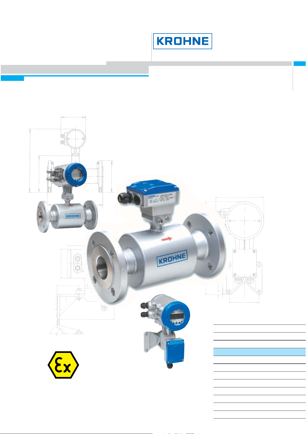
Universal 3-Beam
ultrasonic flowmeter
UFM 3030 K/…EEx compact ultrasonic flowmeter
UFC 030 F/…EEx ultrasonic flow converter
UFS 3000 F/…EEx ultrasonic flow sensor
Subject to change without notice.
Electromagnetic flowmeters
Variable area flowmeters
Mass flowmeters
Ultrasonic flowmeters
Vortex flowmeters
Flow controllers
Level measuring instruments
Pressure and temperature
Heat metering
Communications technology
Switches, counters, displays and recorders
Engineering systems & solutions
Page 2
General advice on safety
• Do not install, operate or maintain this flow meter without reading, understanding and following
the factory-supplied instru c tions, ot herwise injury or damage may re s ult.
• Read these instructions carefully before starting installation and save them for future reference.
• Observe all warnings and instructions marked on the product.
• Use only mains supply with protective earthing connected.
• Do not use the product with removed covers under wet conditions.
• Consider handling and lift ing instr uc tions to avoid dama ge.
• Install the product securely and stable.
• Install an d conn ect ca bli ng prope r to excl u de dama ge or ha r mf ul sit uat i on s.
• If th e product does n ot operate normall y, refer to the s ervice instructions or refer to qualified
KRO HNE servi c e engineers.
• Ther e are no operator-serviceable parts i nside the product.
The following symbols may appear in this manual or on the product
ATTENTION: Refer to operating and installation instructions!
DANGER: Risk of ele ctric shock!
PROTECTIVE EA RTH (PE) conductor termi nal!
These ter ms may a ppear i n this manual or on the ins trument:
WARNING statement : Ide ntify conditions or practi c e that could result in injury or
loss of life.
CAUTION stat em ent: Identify conditions or practice that could result in damage
to the instrument or other property.
2 UFM 3030
Page 3

Disclaimer
• This document contains important information on the instrument. KROHNE attempts to be as
accurate and up-to-date as possible but assumes no responsibility for errors or omissions. Nor
does KROHNE make any c ommitment to update t he information contained herein . Th is manual
and all other documents are subject to change without prior notice.
• KROHNE will not be liable for any damage of any kind by using its instrument, including, but not
limit ed t o direct, in dir ect, i nci d ent al, pu ni tive and co nse qu en ti a l damage s.
• This disclaimer d oes not apply in ca s e KROHNE has act ed on purpose o r with gross negligence.
In the event an y appli ca bl e law doe s not all ow s uch limi ta ti ons on im pli ed wa rranti es or the
exclus ion of limitatio n of cer tain damages, yo u m ay, if such l aw applies to you, not be s ubject t o
some or al l of the above dis cl aim e r, exc lu si on s or limi t at i ons.
• Any instrument purchased from KROHNE is wa rranted in accordance with the relevant product
documentation and our Terms and Conditions of Sale.
• KRO HNE reserves th e right to alter the content of its document s, includi ng this discl aimer in any
way, at any time, for any reason, without prior notification, and will not be liable in any way for
possible consequences of such changes.
Product liability and warranty
• Responsibility for suitability and intended use of this ultrasonic flow meter rests solely with the
user. Improper installation and operation of the flow meter (system) may lead to loss of warranty.
• In addit i on, th e Terms an d Condition s of Sal e are ap pli cab l e and are the bas is fo r the purcha se
contract.
• If flow meters need to be returned to KROHNE, please note the information given on the last
pages of the installation and opera ting instruc tions. KROHNE regrets t hat they can not repair or
check flow meter(s) unless accompanied by t he completed f orm (see last pages of the
inst allation and operating instructions).
Items included with order
• UFM 30 30 ultrasonic flo w meter, co mp ri s ing of a flo w sensor, UFS 3000 and a f low co nvert er,
UFC 030 either built t ogether as a compact s yst em or suppl ied as two separate piece s , in th e
size as indicated on t he packaging box
• Signal cable (only in case of a separate system)
• Special tool for opening the convert er housing
Documentation suppli ed
• Condensed installation and operating manual
• For Ex-u nits: installation an d operating instruction s for use in hazardous ar eas
• Instruction card: overview of the configuration menu and display markers
• Service Handbook
• Approval documents, unless reproduced in the installation and operating instructions
• Report of factory settings of the flow converter
• Certificate of system calibration data
This instrument is developed and manufactured by:
KROHNE Altometer
Kerkeplaat 12
3313 LC Dordrecht
The Net h erl ands
For information, maintenance or service please contact your nearest local KROHNE representative.
UFM 3030 3
Page 4

WARNING!
No changes ma y be ma de to the devices. Unauthorized changes m ight affec t the
explosion safety of the devices.
Be sure to follow these instructions!
IMPORTANT!
• The prescriptions and regulations as well as the electrical data described in the
EC type examination certificate must be obeyed.
• Beside the instructi on s f or electrical installations in non-hazardous locations
according to the applicable national standard (equivalent of HD 384 or IEC 364,
e.g. VDE 01 00), esp ec ially the regula tions in E N 60079-14 " Electrical
inst allations in hazardous loc ations" or equivalent national standard (e.g. DIN
VDE 0165 Part 1 ) must be strictly follow ed.
• Installation, establishment, utilization and maintenance are only allowed to be
executed by personnel with an educa tion in explos ion sa fety!
These add itional instructions are an extensi on to t he installation and operating instructions a nd only
apply to the EEx versions of the UFM 3030 K, UFS 3000 F and UFC 030 F ultrasonic flowmeters. All
technical information as described in the installation and operating instructions is applicable, when
not sp eci fi ca l ly excl u ded, compl e te d or repla ced by th e ins truct io ns i n the se ad di tion al ins truc t ion s.
4 UFM 3030
Page 5

Table of contents
System Components 6
1
1.1 Gene ral i nf orma ti on 6
1.2 Compact flowmeter 6
1.3 Flow sensor 7
1.4 Flow converter 8
1.5 Electrical data 11
2 Technical data 13
2.1 Mains supply 13
2.2 Signal in-/outputs 13
2.3 Ultrasonic sensor circuits 13
2.4 Environment temperatures 13
2.5 Power dissipation 13
3 Electrical connections 14
3.1 Safety instruc tion s 14
3.2 Power supply connection 14
3.3 Equipotential bonding 14
3.4 Standard versions 15
3.5 Namur versions 16
3.6 MODIS versions 17
4 Operation of the flow converter 20
4.1 Operation of the flow converter 2 0
4.2 Connecting cables 20
4.3 Connection diagrams 21
4.4 Namur NE 43 set ti n gs 25
5 Service and maintenance 26
5.1 Introduction 26
5.2 Replacement of electronics unit or power fuse(s) 26
5.3 Replacement of electronics unit 27
5.4 Replacement of mains fuse and analogue input fuses 27
UFM 3030 5
Page 6

1 System Components
1.1 General information
The UFM 3030 ultrasoni c flowmeters in compa c t and separ ate design a re in a cc or dance with the
European Directive 94/9 EC (ATEX 100a) and approved for hazardous classified locations of Zone
1 and 2 by the PTB conf orm to t h e Europ ean S ta nd ards of the EN 500x x se ri es, approval nu mbe r :
PTB 03 ATEX 2021 X.
1.2 Compact flowmeter
The standard UFM 3030 K-EEx compact flowmeter is designed for ambient temperatures (i.e. Ta)
in the ra nge of -40° C up to +65 °C. Th e MO DI S versio n of typ e UFM 303 0 K/i -E E x wi th intri nsic al ly
safe s ignal in-/output s is suit able for ambie nt te mp er atures in the range from -20°C up to +65°C.
The ma xi mum all owed proce ss li qu i d (medi um ) temper a t ure is rest rict ed by the c ombu sti bl e
atmosphere that ( possibly) surroun ds the apparatus, determined by the temperature class of the
atmosp he re , see t a ble bel ow.
Temperature class
T6 80°C 80°C 80°C 80°C
T5 95°C 95°C 95°C 95°C
T4 130°C 130°C 125°C 100°C
T3 180°C 165°C 125°C 100°C
The UFM 3030 K/…-EEx compa c t fl owmeter c onsist s of t he UFC 030…-EEx flow conve rter that is
screw ed on top of the UFS 3000-EEx flow sensor by four hexagon al socket head cap s crews of
size M6. The standard (i .e. non-MO DIS) c om pact flowmeter is marked with one of the codes
below:
Default:
• II 2G EEx de [ib] IIC T6…T3 for the t erminal compa r tment of the fl ow c onvert er housin g in type
of protection inc r eased safety "e" according to EN 50019.
Optional (only if explicitly ordered!):
• II 2G EE x d [ib ] IIC T6…T3 for the terminal compartment of the flow converter housing
designe d as f lam epro o f encl osur e "d " accor din g t o EN 500 18.
The MODIS version of the compact flowmeter, i.e. UFM 3030 K/i-EEx, is marked with one of the
following codes:
Default M O DIS:
• II 2G EEx de [ia/ib] IIC T6…T3 for the terminal compartment of the flow converter housing in
type of protection increased safety "e" according to EN 50019.
Optional MODIS (only if explicitly ordered!):
• II 2G EE x d [ia/i b ] IIC T6… T3 for the terminal compartment of the flow converter housing
designe d as f lam epro o f encl osur e "d " accor din g t o EN 500 18.
For service purpos es the elec tronics unit of the two beam ultras onic converter
UFC 500…-EE x unit can b e replaced by the new UFC 0 30…-EEx electronics unit.
Maximum process liquid temperature at
Ta ≤ 40°C Ta ≤ 50°C Ta ≤ 60°C Ta ≤ 65°C
6 UFM 3030
Page 7
1.3 Flow sensor
1.3.1 Standard instruments
The UFS 3000…-EEx flow sensor is the d efault me as uring unit of t he UFM 3030 (3-beam)
ultra s onic flowme ters. It contai ns t he ultrasoni c s ensor (three pairs of oppos ite t r ansducers) in type
of protection intrinsic safety category "ib" according to EN 50020. All sensor circuits are wired by
separate coaxial cables and connected through SMB connectors, which are marked by the
respective numbers 1.1, 1.2, 2.1, 2.2, 3.1 and 3.2. The flow sensors are available in size DN25 (1”)
up to DN3000 (120”) in diameter.
The UFS 3000…-EEx flow sensor is used in combinati on with the fl ow co nverter un it type UFC
030…-E E x, w h ich is either dir ectl y mounte d on top of t he flow sen sor (compact me te r ) or inst al led
on a d istanc e and c onnected via a cable (s eparate ve r s ion). In t he last c as e the flow sensor as well
as the fl ow conve rt er uni t ar e bot h provided w i th a jun ct i on box, in wh ic h the SM B connectors are
mounted.
The UFS 3000 F/ … -EEx flow se ns or in separate design is the mea s uring unit of the s eparate
flow met e r sys te m. T h ere is a stan da rd versi on, sui ta bl e fo r proce ss li qu id t emp eratu r es f rom - 25° C
up to 180°C and an extended te mp eratur e (XT ) versi on UFS 3000 F/XT-EEx, wh ic h allows a
maximum process temperature of 220°C. Both versions are designed for an ambient temperature
in the rang e of -40°C up t o +65°C.
The UFS 30 00 F/…-EEx flow sensors i n se pa rate design are classified according to the
temperature classification table below.
Temperature class
T6 80°C 80°C
T5 95°C 95°C
T4 130°C 130°C
T3 180°C 195°C
T2 N.A. 220°C
The UFS 3000 F/ … -EEx flow se ns ors are marked with th e explosi on safety cod es :
• Standard UFS 3000 F-EEx: II 2G EEx i b IIC T6…T3
• XT-version UFS 3000 F/XT-EEx: II 2G EEx ib IIC T6…T 2
The intrins icall y safe " ib" ultr as onic s ensor circuit s insi de the UFS 3000…-EEx flow sens or ha ve
the fo l lowin g max imu m val ues (i.e . ent i ty pa rame ters) :
• Maximum input voltage : Vmax = 13.1 V
• Maximum input current : Imax = 600 mA
• Maximum internal capaci tance : Ci = 13.1 nF (maxi m um, 3 sensor c ircuit s)
• Maximum internal inductance : Li = 134 µH (maximum, 3 sensor circuits)
The intrinsical saf e se nso r circuits of the UFM 3030 K/…-EEx compact flow meter
are only internal circuits and not accessible for the user.
Maximum process liquid temperature at Ta = 65°C
Standard design XT-design
UFM 3030 7
Page 8

1.3.2 Optional instruments
The following option s are available to support c ustome rs that have one or mo re ult ra s onic flowmete r
sys te ms (in compact an d/ or sep ar at e desi gn) ba sed on the U FM 50 0…- EE x se rie s and ne ed to
replace the UFC 50 0…-EE x electr onic s unit.
Because the intrinsically safe “ib” sensor circuits of UFS 500…-EEx flow sensor have almost the
same maximum values (i.e. entity parameters) as the UFS 3000…-EEx, it can also be driven by the
UFC 030…-EE x elec tronics unit. Therefore only four of th e six SMB connectors on t he front-en d
printed circuit board of the UFC 030…-EEx electronics unit must be connected to the four SMB
connectors of t he UFS 500…-EEx flo w se ns or . For proper functioning must c onnector number 1.1,
1.2, 2.1 and 2.2 of the UFC 030…-EEx be connected to respective number 4, 3, 1 and 2 of the
UFS 500 … -EEx fl ow s enso r.
An exception applies to the ALTOSONIC V-version UFS 500 F/5STR-EEx, which can only be driven
by five UFC 50 0…-E E x electronics un its.
The intrinsically safe "ib" ultrasonic sensor circuits inside the UFS 500…-EEx flow sensor have the
same maximum values (i.e. entity parameters) as the UFS 3000…-EEx, except for the internal
capaci t anc e, w hi ch is a littl e smal l er, na mel y : Ci = 7.7 nF (maxi mu m, 2 se nso r circu it s)
The UFS 500-EEx as part of th e UFM 500 K…-EEx compact flow me ter is appro ved under number
PT B 01 ATEX 2015 X and the UFS 500 F/… - E Ex fl ow sen s or wi th a separ ate design has app roval
number PTB 01 ATEX 2012 X. See Appendix 1.
1.4 Flow converter
The UFC 030… -EE x flo w convert er co n si sts of an appro ved c y l in dri cal hou si ng, made of a diecasted aluminium alloy (type AX/P/…-EEx with KEM A No. E x-99 .E.8128 U) or of stainless st eel
(type VX -EEx wi th PTB No. Ex -9 6.D.10 68 U). It contai ns two separa te compart m ents, divided from
each other by wall with an integrat ed enc apsulated flameproof termina l feed-through. The ho us ing
of the compact version is screwed on top of the flow sensor, the housing of the separate version is
screwed on an alum inium or s t ainless steel wall-mou nting brac k et. A junction box m ade of diecasted al umi ni um alloy or stainless steel is screwed to the side of the bracket by four M6 recessed
head screws with internal hexagonal socket set (on l y applicable for the flow converter in sepa rate
design).
The flow converter housing is on both ends closed by a threaded cylindrical cover with O-ring
seali n g. Coaxi a l ca bles of typ e RG17 9 or RG31 6 w i th SM B plug s at t hei r end s conne ct th e
intrinsically safe sensor output circuits of the flow converter to the corresponding SMB male-to-male
bulkheads in the junction box.
The equipotential b ondin g c onductor is scr ewed unde r t he ext ernal M 5 U-clamp terminal , which is
located on the mounting flange at the bottom of the neck of the flow converter housing. The flow
converter housing has an ingress protection degree of at least IP67 in accordance with EN 60529.
1.4.1 Electronics compartment
The elec tronic s c om partm ent acc ommodates the UFC 030…-EE x elec tronics unit . The c om partment is designed with type of protection flameproof enclosu re "d" in accordance with EN 50018. I t is
closed by a flameproof display cover with glass window, which is glued and additionally mechanical
support e d by a screwed in ba ck-u p rin g made of alu min u m or stai nl e ss ste el (dep ends on the
materi al of t he hou si ng ). The in terc onne ct i ng part (i. e. ne ck) at t he bot tom of the housin g contain s a
flam eproof c able feed-through, t hr ough which the c oaxial cables r un. T he feed-through pro vi des a
flam eproof s ealing at the bo tt om of the electronics com partme nt.
8 UFM 3030
Page 9

The UFC 030…-EEx electr onic s unit is inse rted into t he electr onics com partment with the he lp of
two slid ing rubb er s that position and fixate the unit at the front of the insi de of th e housi ng. Two M4
screws mount th e unit and a t hird M4 screw fixat es the br ass earth s trip at t he back-end of the fron tend printed circuit board, which contains the integrated voltage/current limiting circuit. The three
screw s are screw e d to t he integ rat ed wall ins id e the el ec tron ics comp a rtm ent. T he on t he front -end
PCB integrated voltage/current limiting circuit provides the ultrasonic sensors inside the flow sensor
with type of protection intrinsic safety category "ib" according to EN 50020.
The voltage/current limiting circuit has the following maximum output values:
• Maximum output voltage : V
• Maximum output current : I
• Maximu m al lowed ext e rnal cap aci ta nce : C
• Maximu m al lowed ext e rnal induc tan ce : L
= 8.15 V
O
= 220 mA
O
= 1. 3 µF
O
= 0.5 mH
O
1.4.2 MODIS electronics units
The MODIS electronics units have type designation UFC 030i-EEx and are provided with two
MODIS modules. The modules provide intrinsically safe signal input/output circuits, which are
accessible by the user for connection in the terminal compartment of the flow converter housing.
Thr ee typ es of modu l es can be used on the UFC 030i -E Ex el e ctr onic s un it , na mel y : P-SA (cu rrent
output), F A-ST (puls e or sta tus output ) and F-PA (fieldbus type Prof ibus).
A combination of two of the above listed modules is installed on the power supply printed circuit
board of the MODIS versions of the UFC 030…-EEx electronics.
1.4.3 Terminal compartment
The termi nal co mp ar tment accommodates s even M4 clamp termi nals for connection of the powe r
supply and the signal in-/output circuits . The termin als are separated from each other b y in s ulati on
plates (eight i n total, from which one at each en d of the row).
The terminal compartment (default in type of protection increased safety “e”) is standard equipped
with two metal cable glands of size M20x1.5 or Pg13.5. The terminal compartment can optionally be
provided as a flameproof encl os ure “EEx d”, in which c as e the custome r m us t use pre-certified
“EEx d” cable glands or conduits.
For flameproof c onduit systems, the terminal compartm ent must have type of protection fl am eproof
enclosure “d ” ac cordi ng to EN 5001 8. T he cond uits m ust be s ealed by “EEx d” approved (in
accordance wit h ATEX 100a directive) sealing d evices (i.e. stopp in g boxes) direct ly at the conduit
entrances of the as flameproof enclosure “EEx d” performed terminal compartment.
1.4.4 MODIS terminal design
The con ne ct ions for the intrinsically safe MODIS input/output circuits consist of four M 4 U-clamp
terminals, separated from the two power supply terminals by an earthed metal plate, which is
screwed to a non- us ed M 4 U- c lamp termi nal. Eight dividing plates of insulating material in-b etween
the seven terminals and at each end of the row separate the terminals from each other and from the
earthed metal housing.
After the power s upply cabl e is c onnected to the ap pr opriate two terminals, these two t er minals a re
covered by a semi-circular i nsulating pl ate to p revent any possibl e contact w ith the intrinsical ly safe
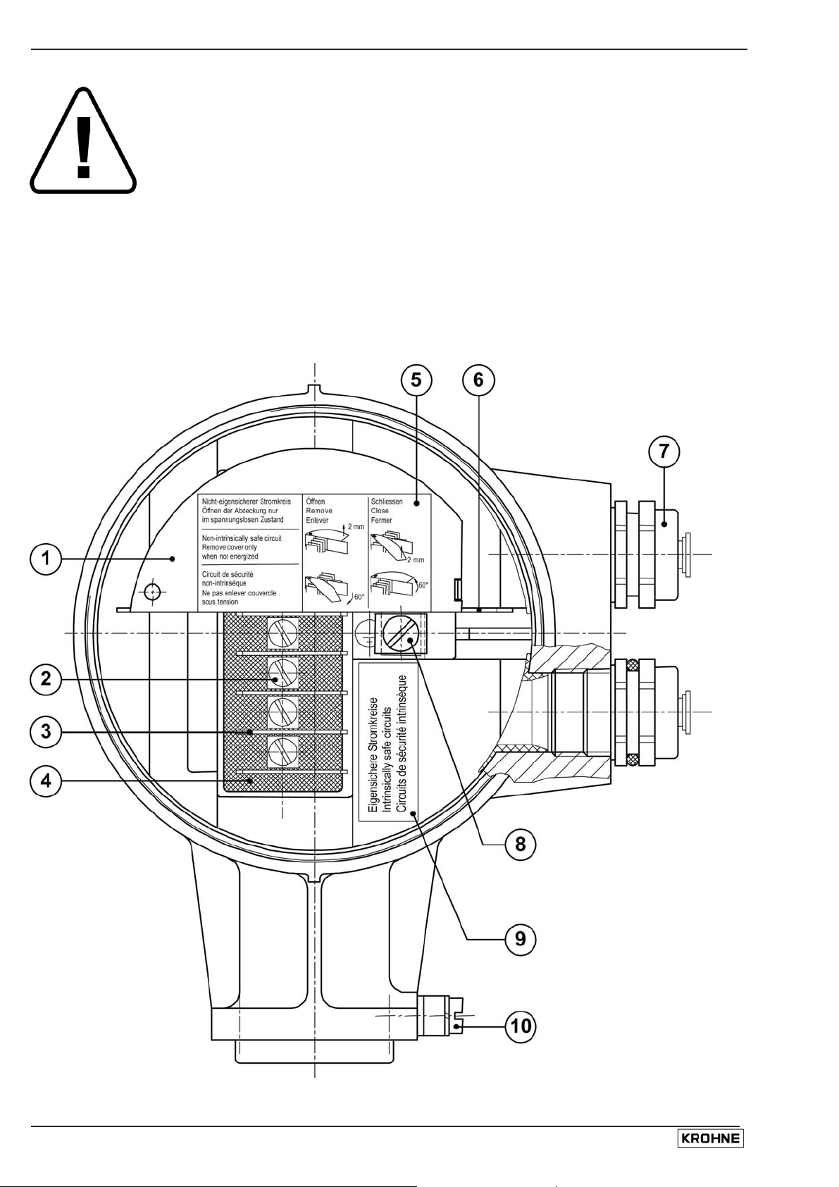
MO DI S con du ct ors. S ee f i gure below .
UFM 3030 9
Page 10
“EEx d” approved cable glands are no part of the standard delivery package, but
must be pro vide d by t he cu sto mer him s elf or ordere d exp li ci t ly at KROH NE.
1) Semi-circular insulating cover plate
2) U-clamp terminal size M4 (7 in total)
3) Dividing plate of insulating material (8 in total)
4) Flameproof terminal feed-through
5) Sticker with handling instruct ions for insula ting cover plate
6) Metal dividing plate intrinsical ly safe and non-intrinsically safe termi nals
7) Cable gland (si z e M20x1.5 or Pg13.5) or cable adapte r
(e.g. M20x1.5 to ½ inch NPT)
8) PE/FE U-clamp terminal size M5
9) Indi cation sticker f or i ntrinsically safe signal in-/output terminal s (MODIS )
10) External U-clamp terminal size M5 for equipotential bonding cable.
Terminal compartment of MODIS versions
10 UFM 3030
Page 11

1.5 Electrical data
1.5.1 Power supply unit
The UFC 030…-EEx electronics unit is equipped with a switching-mode power supply, which is
available in two supply voltage ranges, namely:
• 100…240 V AC power supply;
• 24 V AC/DC power supply.
The power s upplies are available in the standard as well as the MODIS design. The ma in diff erence
between the se ver sio ns i s that the MO DI S versio ns are not pr ovi de d with the anal o gue i npu t A 1 and
its driver logic. The +33 V o utput o f t he secondary winding of the mains transformer t hat pr ovides
the necessar y 24 V for t he analogue input driver logic is therefore not available on the MODI S
versions .
The power s upply’s mains transformer pro vi des the galvanic separation between th e primary circuit
(i.e. main s supply) an d the secondary circuits. The secondary windings o f t he mains transformer
deliver the following output voltages:
• +/- 33 V to supply 24 V to the driver logic of the analogue input A1. This analogue input is only
available on the standard (non-MODIS) versions.
• +/- 24 V for the +6 V and -6 V internal supply voltages of the electronic components of the
UFC 030…-EE x electr onic s unit.
The table below lists the electric al input voltages of the power su pply units, at the primary side of
mains transfo rmer.
Po wer supp l y No mi nal voltage Tolera n ces
24 V AC/DC 24 V AC -10/+15% 21.6 V AC 27.6 V AC 39 Vpeak
24 V DC -25/+33% 18 V DC 32 V DC
100…240 V
100…24 0 V AC -15/+1 0% 85 V A C 264 V AC 375 Vpeak
AC
The table below lists the electric al data of the pow er s upply outputs. Not e that the M ODIS versions
of the 24 V AC/DC and 100…240 V AC power supply units are not equipped with the analogue
inpu t drive r. The seco ndary winding of the mains transformer that supplies the 24 V for the current
outpu t drive r is th eref ore no t used . I t only has a pull -down resi st or of 10 M Oh m tow a rds eart h
potential.
Po wer supp l y out pu t Param eter Minimu m Nomin al Maximum Limit (1)
Voltage +5.4 V +6 V +6.54 V (2) 40 V Electronics pos. supply
Current 225 mA 400 mA 571 mA Voltage -5.2 V -6 V -9 V 40 V Electronics neg. supply
Current 20 mA 50 mA 8 8 mA Voltage 21.6 V 24 V 26.4 V 40 V Analogue input driver (3)
Current 1 mA (4) 100 mA -
(1) Due to t he expl osion s afety measures for the MODIS modules .
(2) Depends on the load.
(3) Only for standard (non-MO DIS) versions.
(4) Depends on what the user connects to the current output.
Mains supply voltage
Minimum Maximum Limit
UFM 3030 11
Page 12

1.5.2 Intrinsically safe sensor circuits
The on the front - end prin ted cir c uit board integrated voltage/current limiting circuits are c onnected
via SM B receptacles of t ype Radiall R114 665 (for coaxial cabl es ) . T hey are soldered into the PCB
at the front side of the board (clos e to the l oc al disp lay uni t). T he conn ec t ions ar e establishe d durin g
the installation of the IFC 030 … - E Ex electronics unit inside the fl ameproof electronics compa r tment
of the flow converter hou s ing by KRO HNE Altomet er personnel.
1.5.3 In-/output circuits
The analogue input circuit A1 is protected against overcurrent by a fuse of type TR5 No. 19372 in
accordance with IEC 127-3 of manufacturer Wickmann. This fuse is rated
T 50 mA, 25 0 V AC and has a breaking capac ity of 35 A.
1.5.4 MODIS design
The MODIS versions of the UFC 0 30i -E E x is available with a 100…240 V A C and 24 V AC/DC
power supply unit. The power supply pri nted circuit board o f the UFC 030i-EEx is therefor e
equipped with two MODIS modules, which are approved under no. PTB 97 ATEX 2265 U.
1.5.5 Power supply units
The power s upply units of the M ODIS ver s ions are based on those of th e standard uni ts, with the
main difference that the analogue input A1 and its c ir c uitry is remo ve d from t he po wer supply
print ed circuit boards. The ±33 V secondary outp ut of the mains t r ansformer is no longer need ed to
generate the ±24 V for the analogue inputs driver logic.
1.5.6 MODIS modules
The modules are suitable for a maximum ambient temperature of 65°C with non-driven electronics
and installed in the closed flameproof electronics compartment of the flow converter housing. The
minimum ambient temp er ature is l imited at -20° C.
Module Terminal designation Function/data
P-SA
I ⊥I
Curren t output (0/4-20 mA), passive
Vi = 30 V, Ii = 250 mA, Pi = 1.0 W
Ci = 5 nF, Li ≈ 0
FA-ST
B1, B1 ⊥ or B2, B2 ⊥
Pulse (frequency) output or status in-/output, all passive
The function can be set by software
Vi = 30 V, Ii = 250 mA, Pi = 1.0 W
Ci = 5 nF, Li ≈0
F-PA
D,D ⊥
Fieldb us mo dul e, ty p e Prof ib us sy st em, pa ss ive
Vi = 30 V, Ii = 380 mA, Pi = 5.32 W
Ci = 5 nF, Li ≈0
The UFC 030i-EEx c an be equipped with a combinati on of two M ODI S modules, see table below.
The possible com binations of th e installed MODIS mo dules a nd the terminal de s ignation in the
terminal compartment of the flow converter housing are listed in table below.
Combination of MODIS modules Designation of intrinsically safe outputs
P-SA FA-ST
P-SA F-PA
I ⊥
I ⊥
FA-ST FA-ST B2
FA-ST F-PA B1
I B1
I D
B2 ⊥
B1 ⊥
B1
D
B1 ⊥
D ⊥
B1 ⊥
D ⊥
12 UFM 3030
Page 13

2 Technical data
2.1 Mains supply
Conn ect or X1 , pi ns 6 an d 7 on pow er sup pl y PCB
24 V AC/D C 24 V AC +15%/-10%, 8 W, Vm = 264 V
24 V DC +33%/-25%, 8 W, Vm = 264 V
100…24 0 V AC 100…240 V A C -15 %/ + 10 %, 11 W, Vm = 264 V
2.2 Signal in-/outputs
Standard versions
Conn ec tor X1 , pins 1, 2, 3, 4 and 5
on po wer supply PCB
MODIS versions
P-SA, FA-ST (passive current out pu t
respectivel y pa s s ive f r equency /
status output)
F-PA ( Fieldbus Profibus) in ty pe of protection Intrinsic Safe ty EEx ia II C, only to be
24 V DC ±10%, 0-22 mA (1 00 m A max. ),
Vm = 264 V
in type of protection Intrinsic Safety EEx ia IIC, only to be
connected t o i ntrinsically safe circuit s wi th maximum values
(i.e. entity parameters) of:
Vi = 30 V, Ii = 250 mA, Pi = 1. 0 W
Ci = 5 nF, Li ≈ 0
connected t o i ntrinsically safe circuit s wi th maximum values
(i.e. entity parameters) of:
Vi = 30 V, Ii = 380 mA, Pi = 5. 32 W
Ci = 5 nF, Li ≈ 0
2.3 Ultr asonic sensor circui ts
6 separate SMB connectors X1, X2,
X6, X 7, X10 and X1 1 on front-end
PCB
in ty pe of protection In trinsi c Safety EEx ib IIC
Maximum values (i. e. enti ty parameters):
Vo = 8.15 V, Io = 220 mA
Lo = 0.5 mH, Co = 1.3 µF
2.4 Environment temperatures
Ambient temperature Ta
• standard version
• MODIS versions
Component ambient temperature Tac
(inside closed converter housing)
• during unfavorable operation
• under faul t con di ti o ns
MO DIS mo dules a mb ient temperature - 20°C …+65°C (with non-driven electronics) (insi de cl os ed
converter housing).
-40°C - +65°C
-20°C - +65°C
≤85°C
≤100°C
2.5 Power dissipation
At nom inal s upply volt age and full load at the outputs, the nominal power dissipation of the
UFC 030…-EE x with the 100…24 0 V AC power suppl y is li mited at a maxi mu m of 11 W and w ith
the 24 V AC/DC it is limited to 8 W.
UFM 3030 13
Page 14

3 Electrical connections
3.1 Safety instructions
These instruments are designed in accordance with IEC 61010-1 for Installation Category 2 and
Polluti on Degree 2. Hazardous voltages ar e present w ithin this produc t during normal opera tion.
They are designed for P r otection Class I and s hould never be operated without protec tive ear thing.
The instruments shall also never be operated with the covers removed. Always follow the basic and
local saf ety prec aut io ns when us ing these inst ru ment s to reduce the ri sk of inj u ry from ele ct ri cal
shock, spread of fire or other dangerous situations.
3.2 Power supply connection
When the UFC 030…-EEx flow converter is connected to the mains supply voltage, the following
environmental requirements must be maintained for safe operation:
Suit able for indoor and outdoor use, protection c ategory IP 67 according to IEC 60529.
a)
Use up to an alt i tud e of 20 00 m above see level.
b)
Suit able for an operation ambi ent t em peratur e r ange - 40°C to +65°C.
c)
Suit able for an s torage temperature range -40°C t o + 80°C.
d)
Suit able for use in atmosph er es with a relative humidity up op 80%.
e)
Mains supply voltage fluctuations for 100 – 240 V AC: -15 to +10%; 24 V AC: -10 to +15%;
f)
DC: -25 to +3 3% of t he sp eci f ied vol ta ge range .
Overvoltages up to category II on the main supply voltage (IEC 60364-4-443).
g)
Connected to protective earth conductor (Protection Class I).
h)
Rated pollution degree 2.
i)
• This instrument is intended for permanent connection to the mains supply. It is
required (e.g. for service) to mount an external switch or circuit breaker in the
proximi ty of the i nstrument for disconn ec tion from the mains . I t must be easi ly
reachable by the operator and marked as the disconn ec ting devic e for this
product. The sw itch or circuit breaker must be sui table for t he applic ation and
shall also be in accordance with the local (safety) requirements and of the
buil ding installation. (IEC 60947-1 /-3).
• The U-clamp terminal size M5, press-fitted in the terminal compartment (near
the mai ns conn ect io n t ermi nal s ), for th e prot ec ti ve eart h conduct or must
alw ay s be conn ect ed to the prot ecti ve eart h con ducto r of th e mains sup ply .
Conductors up to 4 mm
2
(11 AWG) can be connected to this terminal. The
diamet er of the conductor s of t he mains supply, inc luding the protective ear th
conduct o r shall be in acco rdan c e w i th th e gen eral and lo cal require men t s.
• It is not allowed to use the protective earth terminal for any other connection
than the protective earth conducto r.
• IP 67 is only warran ted when suitable cab ling is us ed with the cable glands a nd
covers mounted as speci fied .
3.3 Equipotential bonding
All ultrasonic flowmeters of the UF M 3030 s eries mus t always be in c or porated within t he
equi potent ial bonding system of t he haz ar dous area. For this purpose it is provided with an external
PE-terminal. The external PE-terminal is located on the connecting flange at the bottom of the flow
converter housing and on top of the support of the flow sensor, just below the junction box.
A separate bonding condu c tor mu s t be at le as t 4 mm
mecha ni ca l prot ec t ed, see Clau se 41 3 of H D 384. 4. 4 1 or I EC 364- 4-4 1. M ake sur e th at th e core of
the bonding wir e is properly m ounted under the U-c lamp of the PE-te rminal and th at th e s c r ew is
tightly fixed.
2
(11 AWG) or 2,5 mm2 (14 AWG) in case it is
14 UFM 3030
Page 15

3.4 Standard versions
The field cables enter the terminal compartment of the UFC 030…-EEx flow converter unit (i.e.
power supply, current and signal in-/outputs) and are non-intrinsically safe. To connect external
devices to the in-/output terminals, the wiring requirements for the type of protection of the
compartme nt (standard: increased s afet y "e" , optional: f lameproof "d") m us t be conform to the
international or national standard involved (e.g. DIN VDE 0165, paragraph 5.6).
The PE conductor of the mains s upply must always be connected to the M5 clamp termina l marked
w ith the saf ety ea rt h sy mbol , whi ch i s pres s-fitte d into t he divid ing al u min um w al l of th e fla meproo f
flow conve rte r hou sin g. T h e termi nal arrang ement f or st anda r d ver sio ns w i th ou t NAMU R outp ut s
(non-MODIS) is sh own below.
Symbols and specifications
Milliampère meter Ri ≤ 680 Ohm
Electronic or electr o-mechanical totali z er
U ≤ 32 V DC / 24 V AC; I ≤ 150 mA
Swit c h, N/O cont act 32 V DC / 1. 5 m A
External power supply, DC voltage
Abbreviations and specifications
⊥
A1, A2
P
I/C
L, 1L≈
N, 0L≈
PE/FE
Common earth contac t f or in-/output c ircuits
Analogue input : 0 – 20 mA / I ≤ 25 mA
Pulse output : ≤ 32 V DC / ≤ 24 V AC: I ≤ 150 mA
Current output I : 0 – 22 mA / Rload ≤ 680 Ohm / 24 V DC or
Digital input C : 0 – 5 V DC = ‘low’ / 15 – 32 V DC = ‘high’
Life m ains supply termina l : 100…240 V AC, 24 V AC or 24 V DC
Neutral main s s upply terminal : 100…2 40 V AC, 24 V A C or 24 V DC
Protective Earth / Fun c tional Earth termina l
For passive current out pu t : V
mA
For passive di gital input: V
External power supply, DC or AC voltage
V
≤ 32 V DC / ≤ 24 V AC: I ≤ 150 mA
ext
External current source, e.g. temperature tr ansdu c er
I
≤ 25 mA
ext
= 15 – 24 V DC; I ≥ 22
ext
= 15 – 32 V DC; I ≥ 1.5 mA
ext
UFM 3030 15
Page 16

3.5 Namur versions
See conn ect i on di ag ra m bel ow for stan dard versi o n w it h NAM UR out pu ts (non-M O DIS)
See paragraph 4.4 how to set-up the NAMUR NE 43 failure indication
Symbol s and spec i fic ati on s
Milliampère meter Ri ≤ 680 Ohm
Electronic or electr o-mechanical totali z er
U ≤ 32 V DC / 24 V AC; I ≤ 150 mA
Swit c h, N/O cont act 32 V DC / 1. 5 mA
External power supply, DC voltage
Abbre viations an d spe cificat i ons
⊥
A1
P⊥
P
I/C
L, 1L≈
N, 0L≈
PE/FE
Earth contact for current output and analogue input
Analogue input : 0 – 20 mA / I ≤ 25 mA
Earth con t act fo r pul se out pu t
Pulse output : ≤ 32 V DC / ≤ 24 V AC: I ≤ 150 mA
Current output I : 0 – 22 mA / Rload ≤ 680 Ohm / 24 V DC or
Digital input C : 0 – 5 V DC = ‘low’ / 15 – 32 V DC = ‘high’
Life m ains supply termina l : 100…240 V AC, 24 V AC or 24 V DC
Neutral main s s upply ter mi nal : 100…240 V AC, 24 V A C or 24 V DC
Protective Earth / Fun c tional Earth termina l
For passive current output: V
mA
For passive di gital input: V
External power supply, DC or AC voltage
V
≤ 32 V DC / ≤ 24 V AC: I ≤ 150 mA
ext
External current source, e.g. temperature tr ansdu c er
I
≤ 25 mA
ext
= 15 – 24 V DC; I ≥ 22
ext
= 15 – 32 V DC; I ≥ 1.5 mA
ext
All in-/output circuits must be connected in passive mode. Observe the polarity of
the instru me nt: c ur re nt (I) always fl ows towards A1, P and I/C (current s ink) !
To connect ext er nal devi c es to t he in-/output terminals, the w iring requ irements f or the specific type
of protection of the terminal compartment (standard: increased safety "e", optional: flameproof
enclosure "d") must be respected, see standard EN 60079-14 or the corresponding national
standard.
16 UFM 3030
Page 17

3.6 MODIS versions
The fiel d cables of the non-intrinsical ly safe pow er supply and the intrinsically safe "ia" signal in/outputs enter the terminal compartment of the UFC 030i-EEx flow converter unit via two separate
entrances. To connect external d evices to the intrinsically safe signal ou t pu t t erminal s, the wiring
requirements for their type of protection as well as of the compartment (standard: increased safety
"e", opti onal: f lameproof "d") must be conform to the international or national s tandard involved (e.g.
DIN VDE 0165, paragraph 5.6).The figure below shows the terminal arrangement inside the
termin al com pa rt ment f or th e MO DI S versio ns (i. e. UFC 030 i - EEx) .
Metal dividing plate for separation of IS and non-
1)
IS terminals
Conne c ting terminals for intrinsically sa fe signal
2)
inputs/outputs
Connecting terminals for non-intrinsically safe
3)
pow er s upply
L / N : 100…240 V AC
I⊥ I D D⊥
I⊥ I B B⊥
1L≈ / 0L≈ : 24 V AC/DC
PE : Protective Earth
FE : Functional Earth
4)
Cable entrance for intrinsically safe sensor cable
5)
Cable e ntranc e for non-intrinsically saf e power
supply cable
NC: Not connected
Ter min al arran g eme n t of M ODI S versio ns i n
terminal compartment .
The PE conductor of the mains s upply must be connected to the M5 clamp terminal marked with the
safe ty earth symbol, which is press-fitted into the dividing aluminum wall of t he flamepr oof f low
converter housing. The following table below lists the electrical data of the non-intrinsically safe
power supply.
Power Supply Electrical data
24 V AC/DC
terminals 1L≈, 0L≈, FE
24 V AC +15%/-10%, 48 - 63 Hz, 8 W of
24 V DC +33%/-25%, 8 W
100…240 V AC
100…240 V AC +10%/ - 15%, 48 - 63 Hz, 11 W
termin al s L, N, PE
The non-i nt ri ns ical l y saf e termin als for co nnec t io n of the powe r sup ply (L, 1L≈ and N, 0L≈) mus t be
connected in acco rdance with the r elevant s tandard cod e of practic e for electri c al apparatus
intended for use in potenti ally hazardous l ocations, type of protection increased safety "e" or type of
prote c tion flameproof enclosure "d", depending on the type of prot ec tion of the termin al
compartment of the flow converter housing.
UFM 3030 17
Page 18

Passive count er w i t h exte rnal pow e r suppl y
(*) Only if measuring devices are explosion protected!
18 UFM 3030
Page 19

MODIS signal in- and output connections
(*) Only if measuring devices are explosion protected!
UFM 3030 19
Page 20

4 Operation of the flow converter
4.1 Operati o n of the flow converter
The UFC 030…-EEx electronics unit of the UFM 3030 K/…-EEx compact flowmeter and the UFC
030 F/…-EEx flow converter in remote design is equipped with a display unit that contains magnetic
sensors (Hall-sensors). T he sen s or s enable setting of the UFC 030…-EEx el ec tronics t o be se t or
reset with th e hel p of the wit h th e apparat us de li ve red ba r ma g ne t wi th ou t openi n g the flame proo f
elect ro nic s co mpa rt ment in th e haza rdou s area. Con sul t th e stan da rd I ns t all at io n and O pe rati n g
Instructions (i.e. Part B) for the program functions of the software of the UFC 030…-EEx electronics
unit.
4.2 Connecting cables
The below described cables are shown in the connection diagram of these
additiona l Installation and Operatin g Instructions .
Cable A
Cable B Mains power supply cable. This cable type must also be in accordance with clause
Cable C MR06 coaxia l cabl e ( only for remote de fault ve r s ion), to be supplied by KROHNE
Cable D MR04 coax ia l cab l e (onl y for remot e op t ion al versio n), al so s u ppli e d by KROHNE
Equipotential
bonding
conductor
Signal cable for current outp ut and binary in -/outputs (puls e and status output).
This cable type must be in accordance with clause 9 of the EN 60079-14
"Elect ri cal installations in hazardous locations" or an eq uivalent national standard
(e.g. DIN VDE 0165 Part 1).
9 of the EN 60079-14 "Electrical installations in hazardous locations" or an
equi v alent nati onal s tandard ( e.g. DIN VDE 0165).
Rated vol tage: ≥ 500 V
Examples: H07..-., H05..-. to HD 21.S2 or HD22.S2
Altometer.
Techni cal dat a:
Test voltage: ≥ 500 V
Diameter of strand (core and screen): ≥ 0.1 mm
Distribute d c apaci tance (core/screen): 67 pF/m
Distribute d induc tance (core/screen): 0.4 µH/m
Altometer. This cable has the sa me technical data as cable C ab ove, e xcept that it
cont ains four coaxial c ables i n stead of six for the MR06 ca ble.
Mini mum cross-sectio nal area;
• unprot ec ted: 4 mm
• protected by metal conduit: 2.5 mm
2
(11 AWG)
2
(14 AWG).
20 UFM 3030
Page 21

4.3 Connection diagrams
The foll ow i ng diag rams sh ow the conn ect io n di agr ams of resp ect ive ly t he compa ct ult raso ni c
flow met e r syst e m and rem ot e ul t rason i c flowmete r sy ste m (d ef au lt ). Th e pi ctu re in the frame shows
the c onnecting terminal s of t he UFC 030i-EEx (non-MODIS version) electronics unit.
UFM 3030 K/…EEx compact flowmeter
UFM 3030 21
Page 22

UFS 30 00 F/…EEx (s ensor) + UFC 030 F/ … EEX ( c onvert er) wit h c onnection cab le between
sensor an d co n ve rte r.
22 UFM 3030
Page 23

The following f igures show the connection diagram of the optional versions , i. e with UFS 500…-E Ex
flow se nso r. Note in t hi s case two of the i ntrinsically saf e sensor outputs of t he UFC 030…-EEx
electronics unit (no. 3.1 an d 3.2) ar e not connected.
UFM 5 30 K/… E Ex com pact flowmeter (opti on) for High Pressure
UFM 3030 23
Page 24

UFS 500 F/ …EE x (sen sor) + UFC 030 F/ …EEx ( con ve rte r ), opti o na l fo r High Temp erat u re / High
Pressure with connection cable between sensor and converter.
24 UFM 3030
Page 25

4.4 Namur NE 43 settings
The UFM 30 30 …EEx and UF C 030 … EE x can be s et -up su ch tha t the Current Ou t put fun ct i ons are
accordi ng to Namur NE 43. Thi s m eans the current will go either to 3.6 or to 21.5 mA (failure val ue
can be user defined, normal operating limits are between 3.8 and 20.5 mA) in case the instrument
indi ca tes a f ail ure .
When the failure is no longer indicated, the instrument will automatically return to the measured
curre nt out put again. For a full descriptio n of t he failure pleas e refer to the “Short form Operating
and installation instructions.”
Standard each Namur device is programmed to give a 3.6 mA output in case of failure.
To program the UFM for Namur settings, the steps as described below should be followed:
3.04.02 Direction Forward
3.04.03 Range Other
3.04.04 0 pct 04 MA
3.04.05 100 pct 20 MA
3.04.07 ERR INDIC IERR=3.6 MA or I E RR= 21.5 MA
UFM 3030 25
Page 26

5 Service and maintenance
5.1 Introduction
Contac t your nearest local KROHNE r epresentative for ordering information of th e UFC 030…-EEx
electronics u ni ts and/or fuses.
The UFM 3030 ultrasonic flowmeters are maintenance free with regard to the flow metering
properties. Within the scop e of t he peri odical ins pections, which are re quir ed for electri c al apparatus
that is installed and used in a hazardous classified location, it is recommended to check the
flam eproof c onve rter housing on signs of corrosion and dama ges.
5.2 Replacement of electronics unit or pow er fuse(s)
The following instructions must always be carefully followed, if the flow converter
housing in which the UFC 030…-EEx is installed has to be opened respectively
closed again!
Before opening:
• Make absolu tely sure t hat th er e is no explosion hazard!
• Gas-free certificate!
• Make s ure that all connecting cabl es are saf ely i s olated from all external so ur c es!
• Allow th e pre s c ribed wai ting ti me to elapse before opening the housing: 20 minutes for
temperature class T6 and 11 mi nutes for temperatur e class T5
When the instructions above are stric tly followed, the cover (inclu des a gl ass window) of t he
electronics compartment may be removed. First unscrew the recessed head screw of the
interlocking device by a hollow-head scr ew wrench size 3, until the cover can rotate freely. Unsc re w
the cover with the special plasti c wrench (black) that is suppl ied wi th the apparatu s.
After opening:
• The c opper g ro unding s trip at t he back of the electr onics unit must be sec urely screwed to the
housing (bac k - end of electronics comp artmen t ) by scr ew C (see f igure below). The electronics
unit is screwed into the el ectronics compart men t by two screws B. Before screws B and C can
be accessed, t he display unit must be removed via screws A.
• Before the cover is screwed back into the housing, the screw-thread must be clean and wellgreased with an acid and resin-free grease, e.g. silicone grease.
• Screw the cover as tight as pos s ible into t he housi ng by h and, until it c annot be opened by hand
anymore. Screw the recessed head screw of the interlocking device tight.
Display unit (left) Electronics unit after removal of display unit (right).
26 UFM 3030
Page 27

5.3 Replacement of el ectronics unit
Refer to the standard ins tallati on and operating i nstructions f or detailed information about res ett ing
and reprogramming the new electronics unit after replacement. Important customer specific data
(like the value of the internal tota lis er) should be noted before repl acing the UFC 0 30…-EEx
electronics unit !
Before commencing work, note the “Before opening” instructions, then continue as follows:
Remove th e co ve r of th e el ect roni cs compartment.
1)
Unscrew the two sc r ews A of the displ ay unit and turn displa y unit carefully a s ide or remove
2)
the unit completely by taking out the flat cable connector.
Unscrew the two mounting screws B of the electronics unit as well as screw C, which fixes the
3)
copper earth s trip at t he back of the housin g. A screwdriver with a long shaft (200 mm) can
best b e used to unscrew C (e.g. screwdriver type Philips No. 2).
Carefu lly pull the electronics unit s lightly out of the co nverter ho us ing, unti l the SMB
4)
connectors of th e c oaxia l cabl es can ea s ily be unplugged. Then remove the complete
electronics unit from the housing.
Carefu lly ins ert the new electronic s unit until the numbe re d SMB connectors ca n be
5)
connected to the corresponding numbered SMB receptacles on the electronics unit. Then
mount the unit completely into the housing and fix the screws. First C, then B and finally screw
the display unit on the electronics via screws A, after the flat cable connector is connected.
Screw the cover of the electronics compartment back into the housing.
6)
Note th e “Af te r openi n g" in stru cti o ns duri ng reass em bli n g.
Caref ully keep t he coaxial c ables to the side of the ho us ing, while inserting the
electronics unit into respectively removing it from the converter housing. This is to
prevent damaging of the coaxial cables!
5.4 Replacement of mains fuse and analogue input fuses
Before commencing work, note the “Before opening” instructions, then continue as follows:
Remove th e co ve r of th e el ect roni cs compartment.
1)
Unscrew the two sc r ews A of the displ ay unit and turn the display unit carefully aside .
2)
The fuse-holder, in which the mains fuse in accordance with IEC 127-2 size Ø5 x 20 mm is
3)
mounted , is now accessi ble to replace the defect power fuse by a new fuse wit h the same
rating. The 100…240 V AC power supply (see figure 7 on the next page) is provided with a
fuse rated at T 0.8 A / 250 V, the 24 V AC/DC power supply has a fuse of T 1.25 A / 250 V
(see figure 8). The analogue input c ircuit A1 is pr otected by a su b-miniature fuse of ty pe TR 5
that are rated T 50 mA / 250 V according to IEC 127-3 publication. The MODIS versions have
the same power fuses and locations as the standard (non-MODIS) versions, but they do not
have analogue input fus es .
Reasse mbl e the un it in reverse or de r (p oin t s 2 and 1).
4)
Note th e “Af te r openi n g" in stru cti o ns duri ng reass em bli n g.
UFM 3030 27
Page 28

Power supply PCB - 100…240 V AC standard
(non-MODIS).
Power supp ly PCB - 24 V AC/ DC standard
(non-MODIS).
28 UFM 3030
Page 29

Appendix 1 Declaration of conformit y
UFM 3030 29
Page 30

Appendix 2 Data plates
UFM 3030 K-EEx + UFM 530 K-EEx UFM 3030 K/i-EEx (MODIS)
UFM 3030 K-EEx + UFM 530 K-EEx (NAMUR) UFC 030 F-EEx
30 UFM 3030
Page 31

UFC 030 F/i -EEx (MODI S) UFC 030 F-EEx ( NAMUR)
UFS 3000 F–EE x + UF S 30 00 F/ X T -EE x
(extended temperature version)
UFS 300 0 F-EEx (sta ndard version) + UFS 3000
F/XT-EEx (e xten de d te mperat u r e ver si on )
UFS 500 F-EEx + UFS 500 F/HT -EEx
UFM 3030 31
Page 32

Notes
32 UFM 3030
Page 33

Australia
KROHNE Australia Pty Ltd
Quantum Business Park
10/287 Victoria Rd
Rydalmere NSW 2116
TEL.: +61 2 8846 1700
FAX: +61 2 8846 1755
e-mail: krohne@krohne.com.au
Austria
KROHNE Austria Ges.m.b.H.
Modecenterstraße 14
A-1030 Wien
TEL.: +43(0)1/203 45 32
FAX: +43(0)1/203 47 78
e-mail: info@krohne.at
Belgium
KROHNE Belgium N.V.
Brusselstraat 320
B-1702 Groot Bijgaarden
TEL.: +32(0)2-4 66 00 10
FAX: +32(0)2-4 66 08 00
e-mail: krohne@krohne.be
Brazil
KROHNE Conaut
Controles Automaticos Ltda.
Estrada Das Águas Espraiadas, 230 C.P. 56
06835 - 080 EMBU - SP
TEL.: +55(0)11-4785-2700
FAX: +55(0)11-4785-2768
e-mail: conaut@conaut.com.br
China
KROHNE Measurement Instruments
(Shanghai) Co. Ltd., (KMIC)
Room 1501, Tower A
City Centre of Shanghai
100 Zun Yi Road
Shanghai 200051
TEL.: +86 21 6237 2770
FAX: +86 21 6237 2771
Cellphone: +86 (0) 139 01954185
e-mail: info@krohne-asia.com
CIS
Kanex KROHNE Engineering AG
Business-Centre Planeta, Office 403
ul. Marxistskaja 3
109147 Moscow/Russia
TEL.: +7(0)095-9117165
FAX: +7(0)095-9117231
e-mail: krohne@dol.ru
Czech Republic
KROHNE CZ, spol. s r.o.
Sobe˘s˘ická 156
CZ-63800 Brno
TEL.: +420 545 532 111
FAX: +420 545 220 093
e-mail: brno@krohne.cz
Algeria
Argentina
Belarus
Bulgaria
Camaroon
Canada
Chile
Colombia
Croatia
Denmark
Ecuador
Egypt
Estonia
Finland
French Antilles
Greece
Guinea
Hong Kong
Hungary
Indonesia
Ivory Coast
Iran
Ireland
Israel
Japan
Jordan
Kuwait
Latvia
Lithuania
Marocco
Mauritius
Mexico
New Zealand
Pakistan
Peru
Poland
Portugal
Saudi Arabia
Senegal
Slovakia
Slovenia
Sweden
Taiwan
Thailand
Turkey
Tunesia
Venezuela
Yugoslavia
France
KROHNE S.A.S.
Les Ors
BP 98
F-26103 ROMANS Cedex
TEL.: +33(0)4-75 05 44 00
FAX: +33(0)4-75 05 00 48
e-mail: info@krohne.fr
Germany
KROHNE Messtechnik
GmbH & Co. KG
Ludwig-Krohne-Str.
D-47058 Duisburg
TEL.: +49(0)203-301-0
FAX: +49(0)203-301-10 389
e-mail: krohne@krohne.de
India
KROHNE Marshall Ltd.
A-34/35, M.I.D.C.
Industrial Area, H-Block,
Pimpri Poona 411018
TEL.: +91(0)202-7442020
FAX: +91(0)202-7442020
e-mail: pcu@vsnl.net
Iran
KROHNE Liaison Office
North Sohrevardi Ave.
26, Sarmad St., Apt. #9
Tehran 15539
TEL.: ++98-21-874-5973
FAX: ++98-21-850-1268
e-mail: krohne@krohneiran.com
Italy
KROHNE Italia Srl.
Via V. Monti 75
I-20145 Milano
TEL.: +39(0)2-4 30 06 61
FAX: +39(0)2-43 00 66 66
e-mail: info@krohne.it
Korea
KROHNE Korea
Room 508 Miwon Bldg
43 Yoido-Dong
Youngdeungpo-Ku
Seoul, Korea
TEL.: 00-82-2-780-1743
FAX: 00-82-2-780-1749
e-mail: krohnekorea@krohnekorea.com
Netherlands
KROHNE Altometer
Kerkeplaat 12
NL-3313 LC Dordrecht
TEL.: +31(0)78-6306300
FAX: +31(0)78-6306390
e-mail: postmaster@krohne-altometer.nl
Netherlands
KROHNE Nederland B.V.
Kerkeplaat 14
NL-3313 LC Dordrecht
TEL.: +31(0)78-6306200
FAX: +31(0)78-6306405
Service Direkt: +31(0)78-6306222
e-mail: info@krohne.nl
Norway
KROHNE Instrumentation A.S.
Ekholtveien 114
NO-1526 Moss
P. O. Box 2178, NO-1521 Moss
TEL.: +47(0)69-264860
FAX: +47(0)69-267333
e-mail: postmaster@krohne.no
Internet: www.krohne.no
Singapore
Tokyo Keiso - KROHNE Pte. Ltd.
27 Kian Teck Drive Jurong
Singapore 628844
Singapore
TEL.: ++65-62-64-3378
FAX: ++65-62-65-3382
South Africa
KROHNE Pty. Ltd.
163 New Road
Halfway House Ext. 13
Midrand
TEL.: +27(0)11-315-2685
FAX: +27(0)11-805-0531
e-mail: midrand@krohne.co.za
Spain
I.I. KROHNE Iberia, S.r.L.
Poligono Industrial Nilo
Calle Brasil, n°. 5
E-28806 Alcalá de Henares-Madrid
TEL.: +34(0)91-8 83 21 52
FAX: +34(0)91-8 83 48 54
e-mail: krohne@krohne.es
Switzerland
KROHNE AG
Uferstr. 90
CH-4019 Basel
TEL.: +41(0)61-638 30 30
FAX: +41(0)61-638 30 40
e-mail: info@krohne.ch
United Kingdom
KROHNE Ltd.
Rutherford Drive
Park Farm Industrial Estate
Wellingborough,
Northants NN8 6AE, UK
TEL.: +44(0)19 33-408 500
FAX: +44(0)19 33-408 501
e-mail: info@krohne.co.uk
USA
KROHNE Inc.
7 Dearborn Road
Peabody, MA 01960
TEL.: +1-978 535-6060
FAX: +1-978 535 -1720
e-mail: info@krohne.com
Other Representatives
Other Countries
KROHNE Messtechnik
GmbH & Co. KG
Ludwig-Krohne-Str.
D-47058 Duisburg
TEL.: +49(0)203-301-309
FAX: +49(0)203-301 389
e-mail: export@krohne.de
Subject to change without notice
 Loading...