

Page 1
GR
Installation and
Operating Instructions
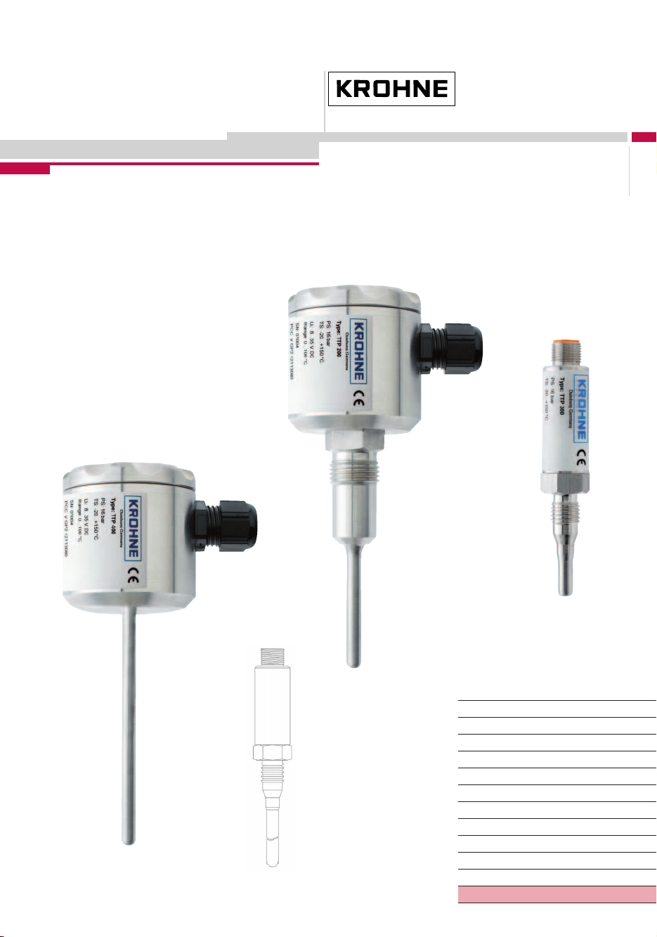
TTP 200/300/400
©
KROHNE 12/2003 7.02278.21.00
Subject to change without notice.
Variable area flowmeters
Vor tex flowmeters
Flow controllers
Electromagnetic flowmeters
Ultrasonic flowmeters
Mass flowmeters
Level measuring instruments
Communications technology
Engineering systems & solutions
Switches, counters, displays and recorders
Heat metering
Pressure and temperature
Page 2

Contents
Safety information..........................................................................................................................3
Items includes with supply............................................................................................................3
Product liability and warranty.......................................................................................................3
CE / EMC / Standards/ Approvals .................................................................................................3
1
Installation...........................................................................................................................4
1.1 Mechanical installation..........................................................................................................4
1.2 Process connections.............................................................................................................4
Electrical connection..........................................................................................................5
2
2.1 External signal converter ......................................................................................................5
2.2 With integrated signal converter............................................................................................6
2.3 Start-up ................................................................................................................................. 6
2.4 Operator control ....................................................................................................................6
3
Fault diagnosis and corrective action...............................................................................7
4
Technical data ..................................................................................................................... 8
4.1 Technical data.......................................................................................................................8
4.2 Dimensions ...........................................................................................................................9
4.2.1 TTP 200 ................................................................................................................................ 9
4.2.2 TTP 300 ................................................................................................................................ 9
4.2.3 TTP 400 .............................................................................................................................. 10
Ordering code ...................................................................................................................11
5
5.1 Ordering code .....................................................................................................................11
5.2 Spare parts .........................................................................................................................12
5.3 Accessories ........................................................................................................................12
6
Product description .......................................................................................................... 13
6.1 Applications ........................................................................................................................13
6.2 Functional principle ............................................................................................................. 13
6.3 Construction........................................................................................................................ 13
6.3.1 Pt100 resistance performance and wiring methods ............................................................13
6.3.2 Pt100 tips and response times............................................................................................ 14
6.4 Features.............................................................................................................................. 14
If you need to return a device for testing or repair to KROHNE...............................................15
2 Installation and Operating Instructions TTP x00
Page 3

Safety information
Please read this manual carefully, and also take note of country-specific installation standards
(e.g. the VDE regulations in Germany) as well as prevailing safety regulations and accidents
prevention rules. For safety and warranty reasons, any internal work on the instruments, apart
from that involved in normal installation and electrical connection, must be carried out only by
qualified KROHNE personnel.
Items includes with supply
• Measuring instrument
• Hygienic adapter
• Installation and operating instructions
Product liability and warranty
Responsibility for suitability and intended use of these instruments rests solely with the operator.
Improper installation and operation of the instruments may lead to loss warranty.
In addition, the “General conditions of sale” forming the basis of the purchase contract are
applicable.
If instruments need to be returned to KROHNE, please note the information given on the last-butone page of these instructions.
KROHNE regrets that it cannot repair or check your instruments unless accompanied by a fully
completed Service and Repair sheet.
CE / EMC / Standards/ Approvals
The product bears the CE marking on account of compliance with and application of the following
standards:
EMCG (89/336/EEC)
EN 50081-1 EN 55022 Class B
EN 61000-6-2 EN 61000-4-2 ESD 4/8 kV
EN 61000-4-3 HF radiated 10 V/m
EN 61000-4-4 Burst 4 kV
EN 61000-4-5 Surge 1 kV sym., 2 kV unsym.
EN 61000-4-6 HF cable 10 V
Installation and Operating Instructions TTP x00 3
Page 4

1 Installation
1.1 Mechanical installation
• Use only the recommended sleeves or adapters. If other systems are used, no guarantee can
be given for proper functioning or leak-tightness.
• Do not use Teflon or paper gaskets for the hygienic process connections featuring a conical
seal.
• The tightening torque for the sleeve should be between 10 and 20 Nm.
1.2 Process connections
The hygienic weldable process sleeves are easy to weld into tanks and pipes. The marking points
to the centre of the future position of the cable gland or M12 connector. This form of assembly
allows installation in conformity with standards of hygiene (to EHEDG, FDA).
Various hygienic adapter sleeves (see Accessories) are available for fitting to other process
connections.
• Process connection G1/2“h is the hygienic standard connection with conical seal.
• For installation in small-diameter pipelines it is recommended to use the hygienic M12 system
(from DN 15).
• When using a sliding sleeve, please use the threadless variant. The clamp cone forms a
hygienic seal with the protective tube.
• A standard G1/2“ connection is available for applications with no hygiene requirements (e.g.
cooling water).
4 Installation and Operating Instructions TTP x00
Page 5
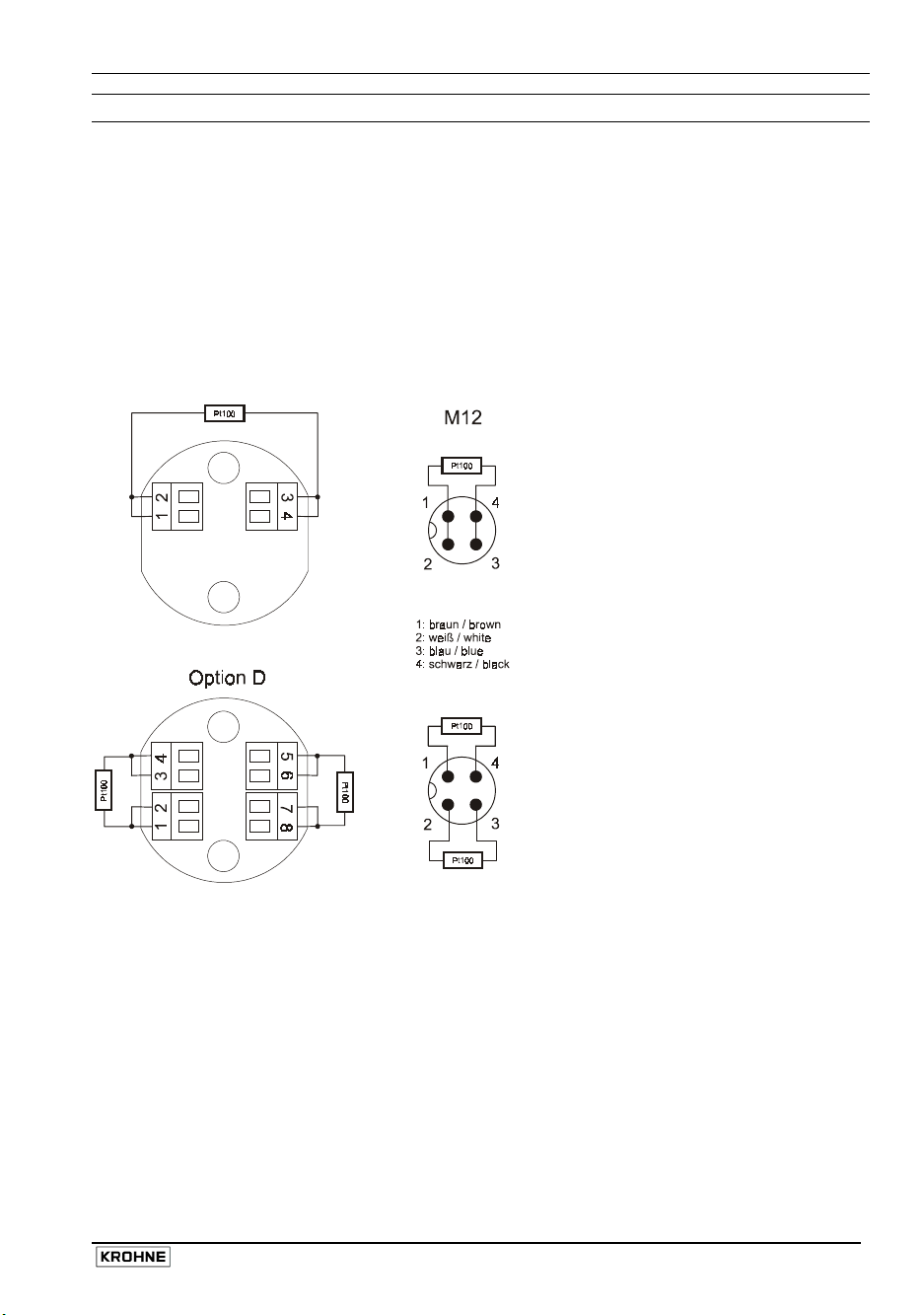
2 Electrical connection
2.1 External signal converter
Terminals 1, 2 and 3, 4 are used for connecting up the Pt100 sensor. You can, as required,
connect up in 2-, 3- or 4-wire technology.
• The 2-wire connection should not be used when particularly high accuracy is required and
where the connecting cables are of longish length.
• When using a 3-wire connection, make sure that all wires have the same cross-sectional area.
The same options are available for the double Pt100, but if connection is made with an M12
connector then only the 2-wire connection may be used.
Installation and Operating Instructions TTP x00 5
Page 6

2.2 With integrated signal converter
Terminals 1 and 2 are used for the infeed via a 4...20 mA current loop. As supply voltage, at least
8 V must be available at the module. Do not use any voltage supply higher than 28 V. The pin
assignment for the M12 connector is shown in the connection diagram. Please pay regard to the
respectively valid wiring regulations.
2.3 Start-up
• Check the leak-tightness at the sleeve.
• Make sure that the cable gland is tight or, as the case may be, the M12 plug connector is
properly screwed down.
• After powering the unit, check for correct functioning.
2.4 Operator control
External signal converter
Refer to the directions supplied with the evaluator. Set the measuring range and type of
connection at the unit.
With integrated signal converter
You can program the measuring range with the programming adapter, available as an accessory,
and the associated PC software. Refer to the operating instructions supplied with the
programming adapter.
6 Installation and Operating Instructions TTP x00
Page 7

3 Fault diagnosis and corrective action
In the event of a fault or maloperation, please go through the various faults listed in the table. Do
not attempt to disassemble the device.
Should you fail to locate the fault, please contact our Technical Service.
Fault Cause Action/elimination
With Pt100 connection
Incorrect display
Terminal assignment is
incorrect
Cable break Measure continuity Error display
Short-circuit Check wiring
With integrated signal converter
Incorrect current signal
Supply voltage at module
< 8 V
Incorrect measuring range Correct the programming
Cable break Check continuity of cables No current signal
Supply polarity incorrect Reverse terminals 1, 2
Current signal > 23 mA Short-circuit Check wiring
Check terminal assignment
Load impedance too high,
voltage too low
Installation and Operating Instructions TTP x00 7
Page 8

4 Technical data
4.1 Technical data
Connection head Stainless steel V2A 1.4305
Cable gland M16 (only TTP 200/400) Electrical connection
M12 connector
Type of protection IP 67
Ambient temperature –20...+60 °C
Process connections
Protective tube Dia. 6 mm x 1 mm; V4A 1.4571
Positioned lengths (mm) 20, 50, 100, 150, 250 (others on request)
Sensor element Pt100 DIN EN 60751 Cl. A (dual type also possible)
Response time t90 Dia. 6 mm: 7 s; dia. 4 mm: 6 s; dia. 3 mm: 1.5 s
Process temperature range –20...+170 °C
Operating pressure Max. 16 bar
With direct Pt100 connection
Output Screw terminals for 2-, 3-, 4-wire connection
With integrated head transmitter
Supply voltage 8...28 V DC (from current loop)
Output 4...20 mA
Accuracy ± 0.1% of full-scale range
Threaded socket G1/2“h; V4A 1.4571
Threaded socket M12h; V4A 1.4571
Push-in connection via protective tube dia. 6 mm
Threaded socket G1/2; V4A 1.4571
8 Installation and Operating Instructions TTP x00
Page 9

4.2 Dimensions
4.2.1 TTP 200
4.2.2 TTP 300
Dimensions in mm
Installation and Operating Instructions TTP x00 9
Page 10

4.2.3 TTP 400
Dimensions in mm
10 Installation and Operating Instructions TTP x00
Page 11

5 Ordering code
5.1 Ordering code
Identification Key Temperature Sensor
VGP 2 4 1
TTP 200 (M 16)
TTP 300 (M 12)
2
Insertion length
1
2
3
20 mm
50 mm
100 mm
Electrical Connection
Screwed cable gland M 16 (for TTP 200 only)
1
Plug M 12
2
Sensor tips
1
2
3
150 mm
4
250 mm
5
Sensor tip 6 mm
Sensor tip 4 mm
Sensor tip 3 mm
Signal output
PT 100 resistor
1
TTP 200 4-20mA, measuring range -10 …+40 °C
2
3
4
5
TTP 300 4-20mA, measuring range -10 …+40 °C
2
3
4
5
4-20mA, freely programmable on site
6
TTP 200 4-20mA, measuring range 15 ... +100°F
A
B
C
D
TTP 300 4-20mA, measuring range 15 ... +100°F
A
B
C
D
4-20mA Customer specific measuring range
K
Options
Without
0
Accessories
0
1
4-20mA, measuring range -10 …+50 °C
4-20mA, measuring range -10 …+100 °C
4-20mA, measuring range -10 …+150 °C
4-20mA, measuring range -10 …+50 °C
4-20mA, measuring range -10 …+100 °C
4-20mA, measuring range -10 …+150 °C
4-20mA, measuring range 32 ... +120°F
4-20mA, measuring range 32 ... +210°F
4-20mA, measuring range 32 ... +300°F
4-20mA, measuring range 32 ... +120°F
4-20mA, measuring range 32 ... +210°F
4-20mA, measuring range 32 ... +300°F
Without
Adapter + Software for programming
Certificates
Without
0
VGP2 4 Order designation
Installation and Operating Instructions TTP x00 11
Page 12

5.2 Spare parts
Should a replaceable part of the sensor be lost or damaged, replacements can be ordered on the
basis of the appropriate part number.
Designation Part No.
Housing lid KMD.008.055.100
Cable gland M16 KVV.M16.010.008
Connector insert M12, 4-pin KVV.100.004.000
5.3 Accessories
Designation Type
System G1/2"h TTP 200
System G1/2"h TEF 020 HWN 200
Varivent flange version N HVF 250
Sanitary pipe assembly kit DN 25 HMT 225
Sanitary pipe assembly kit DN 50 HMT 250
Tri-Clamp flange DN 32, DN 40, 2" HTC 250
Process pipe (T-piece with sleeve) HWT 2X0 (DN 25 … DN 100)
System M12h TTP 300
Weldable sleeve, with collar HWN 310
Varivent flange version N HVF 350
Sanitary pipe assembly kit DN 25 HMT 325
Sanitary pipe assembly kit DN 50 HMT 350
Tri-Clamp flange DN 32, DN 40, 2" HTC 350
Process pipe (T-piece with sleeve) HWT 3X0 (DN 15 … DN 100)
Clamp/screw joint system TTP 400
Clamp screw adapter HLC 306
12 Installation and Operating Instructions TTP x00
Page 13

6 Product description
6.1 Applications
The screw-in temperature sensors of the series “with connection head“ are designed to measure
the temperature in all processes where high accuracy and ease of handling are what count. The
various mounting systems and adapters available enable the optimum choice to be made for your
application.
6.2 Functional principle
All temperature sensors of this series feature a Pt100 chip as the sensor element. A platinum
meander applied to a ceramic substrate is trimmed such that its electrical resistance at 0°C is
exactly 100 ohms. This resistance increases by 0.38 ohm for each 1 Kelvin temperature rise. The
exact resistance performance is described in the DIN EN 60751 standard. For our temperature
sensors we use without exception the high accuracy class “A“.
6.3 Construction
The various weldable process sleeves are made of stainless steel to allow installation in
conformity with hygiene requirements. Various evaluation modules are available for evaluation of
the Pt100 signal (see Accessories). A signal converter integrated into the stainless steel
connection head provides a 4...20-mA standardised signal locally, which can be transmitted noisefree direct to the analogue input of an SPC or PLC. It is also possible to install a transmitter for
Profibus PA.
The Pt100 sensor is housed in a rugged 6 mm protective tube of variable length and made of
V4A. Due to the special type of thermal coupling, our temperature sensors achieve very fast
response times. Tapered sensor tips are also available for even higher requirements.
6.3.1 Pt100 resistance performance and wiring methods
Installation and Operating Instructions TTP x00 13
Page 14

6.3.2 Pt100 tips and response times
Tube 6 mm (S 6) Tube 4 mm (S 4) Tube 3 mm (S 3)
Halftime: T50 < 3.0 sec. Halftime: T50 < 2.5 sec. Halftime: T50 < 0.6 sec.
90% - time: T
< 7.0 sec. 90% - time: T90 < 6.0 sec. 90% - time: T90 < 1.5 sec.
90
Tube
Pt100 Chip
6.4 Features
• Sensors for hygienic installation, no elastomers
• Compact design, optionally with head transmitter
• For direct connection to an SPC or PLC (with integrated head transmitter)
• High accuracy (DIN EN 60751 Class A)
• Very fast response times
• Optimised flow geometry
• Food-compatible materials
• No maintenance requirement
• Installation in pipelines DN 15 and higher
• Defined position of the cable connection
• Hygienic adapter sleeves for other process connections
14 Installation and Operating Instructions TTP x00
Page 15

If you need to return a device for testing or repair to KROHNE
Your instrument has been carefully
manufactured and tested. If installed and
operated in accordance with these operating
instructions, your instrument will rarely present
any problems. Should you nevertheless need
to return an instrument for checkout or repair,
please pay strict attention to the following
points:
Due to statutory regulations concerning
protection of the environment and
safeguarding the health and safety of our
personnel, KROHNE may only handle, test
and repair returned instruments that have
been in contact with liquids if it is possible to
do so without risk to personnel and
environment.
This means that KROHNE can only service
your instrument if it is accompanied by a
certificate in line with the following model
confirming that the instrument is safe to
handle.
S P E C I M E N certificate
Company: ……………………………………….. Address: ……………………………………………
Department: …………………………………….. Name: ………………………………………………
Tel. No.: ………………………………………….
The enclosed instrument
Type: …………………………………………………………………………………………………………
KROHNE Order No. or Series No ………………………………………………………………………...
has been operated with the following liquid: ……………………………………………………………..
Because this liquid is
water-endangering * / toxic * / caustic * / flammable *
we have
– checked that all cavities in the instrument are free from such substances *
– flushed out and neutralized all cavities in the flowmeter *
(* delete if not applicable)
We confirm that there is no risk to man or environment through any residual liquid contained in the
instrument.
Date: ………………………….. Signature: ……………………………………………………………..
Company stamp:
Installation and Operating Instructions TTP x00 15
If the instrument has been operated with toxic,
caustic, flammable or water-endangering liquids,
you are kindly requested
• to check and ensure, if necessary by rinsing
or neutralizing, that all cavities in the
instrument are free from such dangerous
substances.
(Directions on how you can find out whether
the primary head has to be opened and then
flushed out or neutralized are obtainable from
KROHNE on request.)
• to enclose a certificate with the instrument
confirming that the instrument is safe to
handle and stating the liquid used.
KROHNE regret that they cannot service your
instrument unless it is accompanied by such a
certificate.
 Loading...